EP3461954B1 - Pile head analysis system, pile head analysis method, and pile head analysis program - Google Patents
Pile head analysis system, pile head analysis method, and pile head analysis program Download PDFInfo
- Publication number
- EP3461954B1 EP3461954B1 EP18196544.3A EP18196544A EP3461954B1 EP 3461954 B1 EP3461954 B1 EP 3461954B1 EP 18196544 A EP18196544 A EP 18196544A EP 3461954 B1 EP3461954 B1 EP 3461954B1
- Authority
- EP
- European Patent Office
- Prior art keywords
- pile head
- pile
- unit
- dimensional model
- images
- Prior art date
- Legal status (The legal status is an assumption and is not a legal conclusion. Google has not performed a legal analysis and makes no representation as to the accuracy of the status listed.)
- Active
Links
Images


Classifications
-
- E—FIXED CONSTRUCTIONS
- E02—HYDRAULIC ENGINEERING; FOUNDATIONS; SOIL SHIFTING
- E02D—FOUNDATIONS; EXCAVATIONS; EMBANKMENTS; UNDERGROUND OR UNDERWATER STRUCTURES
- E02D33/00—Testing foundations or foundation structures
-
- G—PHYSICS
- G06—COMPUTING OR CALCULATING; COUNTING
- G06V—IMAGE OR VIDEO RECOGNITION OR UNDERSTANDING
- G06V20/00—Scenes; Scene-specific elements
- G06V20/10—Terrestrial scenes
-
- B—PERFORMING OPERATIONS; TRANSPORTING
- B64—AIRCRAFT; AVIATION; COSMONAUTICS
- B64C—AEROPLANES; HELICOPTERS
- B64C39/00—Aircraft not otherwise provided for
- B64C39/02—Aircraft not otherwise provided for characterised by special use
-
- E—FIXED CONSTRUCTIONS
- E02—HYDRAULIC ENGINEERING; FOUNDATIONS; SOIL SHIFTING
- E02D—FOUNDATIONS; EXCAVATIONS; EMBANKMENTS; UNDERGROUND OR UNDERWATER STRUCTURES
- E02D13/00—Accessories for placing or removing piles or bulkheads, e.g. noise attenuating chambers
- E02D13/06—Accessories for placing or removing piles or bulkheads, e.g. noise attenuating chambers for observation while placing
-
- E—FIXED CONSTRUCTIONS
- E02—HYDRAULIC ENGINEERING; FOUNDATIONS; SOIL SHIFTING
- E02D—FOUNDATIONS; EXCAVATIONS; EMBANKMENTS; UNDERGROUND OR UNDERWATER STRUCTURES
- E02D5/00—Bulkheads, piles, or other structural elements specially adapted to foundation engineering
- E02D5/22—Piles
- E02D5/223—Details of top sections of foundation piles
-
- G—PHYSICS
- G01—MEASURING; TESTING
- G01C—MEASURING DISTANCES, LEVELS OR BEARINGS; SURVEYING; NAVIGATION; GYROSCOPIC INSTRUMENTS; PHOTOGRAMMETRY OR VIDEOGRAMMETRY
- G01C11/00—Photogrammetry or videogrammetry, e.g. stereogrammetry; Photographic surveying
-
- G—PHYSICS
- G01—MEASURING; TESTING
- G01C—MEASURING DISTANCES, LEVELS OR BEARINGS; SURVEYING; NAVIGATION; GYROSCOPIC INSTRUMENTS; PHOTOGRAMMETRY OR VIDEOGRAMMETRY
- G01C11/00—Photogrammetry or videogrammetry, e.g. stereogrammetry; Photographic surveying
- G01C11/04—Interpretation of pictures
- G01C11/06—Interpretation of pictures by comparison of two or more pictures of the same area
-
- G—PHYSICS
- G01—MEASURING; TESTING
- G01C—MEASURING DISTANCES, LEVELS OR BEARINGS; SURVEYING; NAVIGATION; GYROSCOPIC INSTRUMENTS; PHOTOGRAMMETRY OR VIDEOGRAMMETRY
- G01C11/00—Photogrammetry or videogrammetry, e.g. stereogrammetry; Photographic surveying
- G01C11/04—Interpretation of pictures
- G01C11/06—Interpretation of pictures by comparison of two or more pictures of the same area
- G01C11/08—Interpretation of pictures by comparison of two or more pictures of the same area the pictures not being supported in the same relative position as when they were taken
-
- G—PHYSICS
- G06—COMPUTING OR CALCULATING; COUNTING
- G06T—IMAGE DATA PROCESSING OR GENERATION, IN GENERAL
- G06T17/00—Three-dimensional [3D] modelling for computer graphics
- G06T17/05—Geographic models
-
- B—PERFORMING OPERATIONS; TRANSPORTING
- B64—AIRCRAFT; AVIATION; COSMONAUTICS
- B64U—UNMANNED AERIAL VEHICLES [UAV]; EQUIPMENT THEREFOR
- B64U2101/00—UAVs specially adapted for particular uses or applications
- B64U2101/30—UAVs specially adapted for particular uses or applications for imaging, photography or videography
-
- B—PERFORMING OPERATIONS; TRANSPORTING
- B64—AIRCRAFT; AVIATION; COSMONAUTICS
- B64U—UNMANNED AERIAL VEHICLES [UAV]; EQUIPMENT THEREFOR
- B64U2201/00—UAVs characterised by their flight controls
- B64U2201/20—Remote controls
Definitions
- the present disclosure relates to a pile head analysis system and a pile head analysis method.
- the position of a driven pile head is measured using a global positioning system (GPS), a total station (TS), and the like to determine deviation of the pile core from the design drawing including, for example, data of a computer aided design system (CAD).
- GPS global positioning system
- TS total station
- CAD computer aided design system
- Japanese Unexamined Patent Publication No. 11-325884 describes a technique capable of measuring coordinates of a point to be measured such as a pile head by setting an auto-tracking TS and having an operator carry a target to the measured point and give instructions of measurement.
- Japanese Unexamined Patent Publication No. 2017-96688 acquires a point cloud model by laser scanning from the sky above the construction site.
- the operator scans the entire construction site and acquires point cloud data of the entire construction site, and singles out only a point cloud of a target area including the pile head portions by trimming the acquired data.
- the point cloud data for the entire construction site problematically causes a significant increase in the amount of data.
- the technique of Japanese Unexamined Patent Publication No. H11-325884 increases the distance and time for an operator moving from a pile to another pile, and the technique of Japanese Unexamined Patent Publication No. 2017-96688 further increases the amount of point cloud data.
- US 2017206648 A1 discloses an automated system and method for structural inspection and construction estimation using images from an unmanned aerial vehicle (UAV).
- UAV unmanned aerial vehicle
- EP 2 597 422 A2 discloses an aerial photograph image pickup method and an aerial photograph image pickup apparatus by a small type Unmanned Aerial Vehicle (UAV).
- UAV Unmanned Aerial Vehicle
- JP S63 210614 A discloses a scheme of correcting the verticality of a pile so as to be within an allowable range, using an electronic total station having electronic orbital courts and wireless transmitters, and a piling installation work apparatus 6 with a computer and a display connected to the computer.
- FIG. 1 illustrates an overall structure of a pile head analysis system according to an embodiment of the present disclosure
- FIG. 2 is a control block diagram of the pile head analysis system. A configuration of the pile head analysis system will now be described based on these drawings.
- a pile head analysis system 1 is an analysis system using photogrammetry and includes a movable imaging device 2 capturing a plurality of images for photogrammetry while moving in the sky above a construction site C and an analysis device 3 generating a three-dimensional model from the images captured by the movable imaging device 2 and analyzing a pile head.
- the movable imaging device 2 includes an unmanned aerial vehicle (UAV) 10 as a movable body and a camera 11 mounted on the UAV10 to capture an image for photogrammetry.
- UAV unmanned aerial vehicle
- the camera 11 may capture a still image and a moving image.
- the UAV10 is a flying movable body capable of flying on a predetermined flight path or freely flying via remote control, in the sky above the construction site C.
- the UAV10 includes a gimbal mechanism 10b under a flight mechanism 10a for flight.
- Configurations of control systems installed on the movable imaging device 2 and the analysis device 3 of the pile head analysis system 1 will now be described with reference to FIG. 2 .
- a known technique may be applied to flight control for the UAV10 of the movable imaging device 2, and detailed description will therefore be omitted.
- the movable imaging device 2 includes an imaging control unit 13 and a storage unit 14 in addition to the above-described camera 11 and the GPS unit 12.
- the movable imaging device 2 further includes an operation unit, a display unit, and others, which are not illustrated.
- the imaging control unit 13 is electrically connected with the camera 11 and the GPS unit 12.
- the imaging control unit 13 has a function of controlling the camera 11 to capture images at predetermined imaging intervals in a manner allowing adjacent images to partially overlap with each other and acquiring position information at the time of imaging from the GPS unit 12.
- the imaging control unit 13 stores an image captured by the camera 11 and position information acquired by the GPS unit 12 in the storage unit 14 in a manner associated with each other.
- Examples of the storage unit 14 include a flash memory capable of storing various kinds of information.
- the storage unit 14 mainly stores an image including position information transmitted from the imaging control unit 13.
- the information stored in the storage unit 14 can be transmitted or copied to another storage medium or another device through wired or wireless communication.
- the analysis device 3 mainly includes an image acquiring unit 20, a three-dimensional model generating unit 21, a pile head detecting unit 22, a consistency determination unit 23, and a display unit 24.
- the analysis device 3 stores design information including the coordinates of a point where a pile is driven in the construction site C and specifications such as the shape and the size of a pile, in a storage unit (not illustrated).
- the image acquiring unit 20 acquires an image including position information stored in the above-described storage unit 14.
- the marker is used as a ground control point for associating (associating relative coordinates with absolute coordinates) an image with a point on the ground and also used as a validation point for accuracy check. Furthermore, workability of three-dimensional measurement of a pile head position can be improved by, for example, attaching an aerial survey marker or any mark easily recognized in image processing to a pile head or using the shape of the pile itself.
- the pile head detecting unit 22 detects a pile head from a three-dimensional model generated by the three-dimensional model generating unit 21. More specifically, a pile head is automatically detected using an image recognition technique. In an example not part of the invention, a pile head may be manually detected by an operator visually finding a pile head from the three-dimensional model through the display unit 24. The pile head detecting unit 22 detects the position of a pile core, the height, and inclination of the detected pile head.
- the pile head detecting unit 22 detects XY coordinates (horizontal plane coordinates) of the center point of a cylindrical pile head as the position of a pile core, detects Z coordinates (vertical coordinates) from the ground surface to the top face of the pile as the height of a pile head, and detects an angular difference between a pile core axis and the Z axis (vertical axis) as inclination of the pile head.
- the consistency determination unit 23 determines consistency between the pile head detected by the pile head detecting unit 22 and the specifications of a pile head indicated in design information preliminarily acquired from a storage unit. More specifically, the consistency determination unit 23 determines if each of the position of a pile core, the height of a pile head, and inclination of a pile head falls within a tolerance range for a value indicated in the design information.
- the display unit 24 is, for example, a display of a PC and is capable of displaying information relating to consistency of a pile head determined by the consistency determination unit 23 on a three-dimensional model generated by the three-dimensional model generating unit 21.
- the pile head analysis system 1 configured as above has the movable imaging device 2 capture a plurality of images P1, P2, ..., Pn for photogrammetry at certain imaging intervals while moving in the sky above the construction site C.
- the pile head analysis system 1 further has the analysis device 3 generate a three-dimensional model from the images P1, P2, ..., Pn, detect a pile head, and determine consistency on the pile head.
- the movable imaging device 2 flies in the sky above the construction site C and captures images of the construction site C at certain intervals with adjacent images partially overlapping with each other.
- the imaging control unit 13 acquires position information of the movable imaging device 2 at the time of imaging using the GPS unit 12 and stores an image including the position information in the storage unit 14.
- Step S2 the movable imaging device 2 completes imaging and finishes the flight.
- the image acquiring unit 20 of the analysis device 3 acquires an image including position information from the storage unit 14 of the movable imaging device 2 (an image acquiring process).
- the three-dimensional model generating unit 21 generates a three-dimensional model based on a plurality of acquired images using a technique of photogrammetry (a three-dimensional model generating process). Specifically, the three-dimensional model generating unit 21 estimates an attitude (an exterior orientation) in which each image has been taken and a calibration parameter (an inner orientation) of the camera. The three-dimensional model generating unit 21 further extracts feature points from each image, matches the feature points between images, and generates a stereo model. The three-dimensional model generating unit 21 designates a pixel of an imaged object (for example, a pile head) from a plurality of images and measures a three-dimensional position, which is called manual measurement. In another manner, three-dimensional point cloud data may be generated for an area overlapping between images by automating the manual measurement.
- a technique of photogrammetry a three-dimensional model generating process. Specifically, the three-dimensional model generating unit 21 estimates an attitude (an exterior orientation) in which each image has been taken and a calibration parameter (an inner orientation) of
- the consistency determination unit 23 determines if inclination of a pile head is within a tolerance range. For example, the consistency determination unit 23 calculates a difference between inclination of a pile head and inclination (for example, vertical) of the pile head of the pile head model H0 and determines if the difference in inclination is within a predetermined tolerance range. If the result of determination is true (Yes), in other words, as the first pile head H1 in FIG. 4 indicates, if inclination of the pile head axis H1a is substantially equal (inclination: zero) to inclination of a pile head axis H0a of the pile head model H0, the process proceeds to the next step S9.
- the display unit 24 determines a pile head in which results of determinations at Step S6 to Step S8 are all true (Yes) to be driven substantially in accordance with the design and displays the pile head on the display screen in a manner of normal display.
- the first pile head H1 in FIG. 4 is therefore displayed in normal display.
- the consistency determination unit 23 determines whether consistency determination is completed on all the pile heads detected in the above Step S5. If the result of determination is true (Yes), the routine ends. If the result of determination is false (No), in other words, if consistency of any pile head remains undetermined, the process returns to Step S5, and the consistency determination is performed on the next pile head.
- a warning is displayed on the display screen for a pile head that falls outside the tolerance range.
- This warning display may be changed depending on the type of element (the position of a pile core, the height of a pile head, and inclination of a pile head) that is outside the tolerance range or may be changed depending on the amount of difference.
- the second pile head H2 has a position difference ⁇ H2o that is outside the tolerance range
- the third pile head H3 has a height difference ⁇ H3h outside the tolerance range
- the fourth pile head has an inclination difference ⁇ H4a outside the tolerance range.
- the pile head analysis system 1 of this embodiment has the analysis device 3 acquire a plurality of images of the construction site C imaged by the camera 11 mounted on the UAV10.
- the analysis device 3 generates a three-dimensional model from the images, detects pile heads, and determines consistency on each pile head.
- the group cloud data does not have to be acquired over the entire construction side as a laser scanner acquires. Instead, the group cloud data may be generated only for a necessary range including pile heads, which is sufficient for consistency of the determination. This manner allows a reduction in the amount of data and more efficient analysis of a pile head. In addition, this manner can achieve more consistent accuracy compared to measurement of pile heads by an operator.
- the state of a driven pile can be evaluated by detecting the position of a pile core of the pile head, the height of the pile head, and inclination of the pile head from a three-dimensional model generated based on photogrammetry and determining consistency on each of the elements.
- Such a display as the three-dimensional model M in FIG. 4 makes information relating to consistency of a pile head more comprehensible to viewers, which allows early discovery of a defect in a driven pile head.
- the pile head analysis system, the pile head analysis method, and the pile head analysis program according to the embodiment allow a pile head to be analyzed in a more efficient and consistently accurate manner.
- the pile head detecting unit 22 automatically, or manually in an example not part of the invention, detects a pile head.
- a pile head may be colored at the construction site C before imaging by the movable imaging device 2.
- the color may be used as an element for detecting the pile head from a three-dimensional model. For example, respective different colors may be used for the types of pile.
- a color of an object cannot be recognized in point cloud data generated by a laser scanner; however, photogrammetry can use actual colors of the construction site C for modelization. This allows a pile head to be detected in a more smooth and accurate manner.
- the movable imaging device 2 uses the UAV10 as a movable body; however, in an example not part of the invention, the movable body, for example, may be a manned aircraft.
- the GPS unit 12 is used to measure the position of the movable imaging device 2; in an example not part of the invention, an auto-tracking total station may be used to track the movable imaging device 2 and measure its position.
Landscapes
- Engineering & Computer Science (AREA)
- Physics & Mathematics (AREA)
- Structural Engineering (AREA)
- General Physics & Mathematics (AREA)
- Remote Sensing (AREA)
- General Engineering & Computer Science (AREA)
- Civil Engineering (AREA)
- Mining & Mineral Resources (AREA)
- General Life Sciences & Earth Sciences (AREA)
- Life Sciences & Earth Sciences (AREA)
- Paleontology (AREA)
- Multimedia (AREA)
- Radar, Positioning & Navigation (AREA)
- Aviation & Aerospace Engineering (AREA)
- Software Systems (AREA)
- Geometry (AREA)
- Theoretical Computer Science (AREA)
- Computer Graphics (AREA)
- Length Measuring Devices By Optical Means (AREA)
Description
- The present disclosure relates to a pile head analysis system and a pile head analysis method.
- In construction work, it is important to drive a pile serving as a foundation of a building as instructed in a design drawing because driving pile affects construction of the foundation.. After the piles are driven, the piles are thus to be checked if the positions of pile cores, the heights of pile heads, and others are accurately driven in accordance with the design drawing.
- Conventionally, the position of a driven pile head is measured using a global positioning system (GPS), a total station (TS), and the like to determine deviation of the pile core from the design drawing including, for example, data of a computer aided design system (CAD). In this manner, it is determined whether the pile core is within a tolerance range (within a margin of error in construction) for a design value.
- For example,
Japanese Unexamined Patent Publication No. 11-325884 - Furthermore, as described in
Japanese Unexamined Patent Publication No. 2017-96688 - With the auto-tracking TS as described in the technique of
Japanese Unexamined Patent Publication No. H11-325884 - Furthermore, the technique of
Japanese Unexamined Patent Publication No. 2017-96688 - Particularly, in a large construction site for a large building, the technique of
Japanese Unexamined Patent Publication No. H11-325884 Japanese Unexamined Patent Publication No. 2017-96688 -
US 2017206648 A1 discloses an automated system and method for structural inspection and construction estimation using images from an unmanned aerial vehicle (UAV). -
JP 2011 122313 A -
US 2018/147998 A1 an aerial photogrammetric device and an aerial photogrammetric method using an unmanned aerial vehicle (UAV). -
EP 2 902 744 A1 -
EP 2 597 422 A2 -
JP S63 210614 A installation work apparatus 6 with a computer and a display connected to the computer. - To overcome the above problems, a pile head analysis system, a pile head analysis method, and a pile head analysis program are defined in independent claims. Some embodiments are disclosed in dependent claims.
- According to an embodiment of the pile head analysis system according to the present disclosure using the above means, a pile head can be analyzed in a more efficient and consistently accurate manner.
-
-
FIG. 1 is a drawing of an overall structure of a pile head analysis system according to an embodiment of the present disclosure. -
FIG. 2 is a control block diagram of the pile head analysis system. -
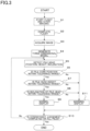
FIG. 3 is a flowchart illustrating a routine of the pile head analysis. -
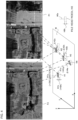
FIG. 4 is a conceptual diagram that illustrates a pile head portion extracted using photogrammetry. - An embodiment of the present disclosure will now be described with reference to the drawings.
-
FIG. 1 illustrates an overall structure of a pile head analysis system according to an embodiment of the present disclosure, andFIG. 2 is a control block diagram of the pile head analysis system. A configuration of the pile head analysis system will now be described based on these drawings. - A pile
head analysis system 1 is an analysis system using photogrammetry and includes amovable imaging device 2 capturing a plurality of images for photogrammetry while moving in the sky above a construction site C and ananalysis device 3 generating a three-dimensional model from the images captured by themovable imaging device 2 and analyzing a pile head. - In the construction site C of this embodiment, driven piles have respective pile heads H1, H2, ... Hm, which have undergone pile head processing, exposed in an excavation pit. In this embodiment, a cylindrical steel pile is used as an example; however, any material and shape of the pile are applicable. Example of the pile may have corners with a rectangular section.
- The
movable imaging device 2 includes an unmanned aerial vehicle (UAV) 10 as a movable body and acamera 11 mounted on the UAV10 to capture an image for photogrammetry. Thecamera 11 may capture a still image and a moving image. - More specifically, the UAV10 is a flying movable body capable of flying on a predetermined flight path or freely flying via remote control, in the sky above the construction site C. The UAV10 includes a
gimbal mechanism 10b under aflight mechanism 10a for flight. - The
camera 11 is supported by thegimbal mechanism 10b of the UAV10 and is free to change directions of imaging using thegimbal mechanism 10b. In this embodiment, thegimbal mechanism 10b maintains the attitude in a manner constantly capturing images of the construction site C in the downward direction from above. - The
camera 11 has aGPS unit 12 capable of receiving a GPS signal. TheGPS unit 12 is capable of measuring the current position of themovable imaging device 2 based on a received GPS signal. - The
analysis device 3 is an information processing terminal such as a personal computer (PC) capable of executing a program for photogrammetry and a program for pile analysis. - Configurations of control systems installed on the
movable imaging device 2 and theanalysis device 3 of the pilehead analysis system 1 will now be described with reference toFIG. 2 . A known technique may be applied to flight control for the UAV10 of themovable imaging device 2, and detailed description will therefore be omitted. - As illustrated in
FIG. 2 , themovable imaging device 2 includes animaging control unit 13 and astorage unit 14 in addition to the above-describedcamera 11 and theGPS unit 12. Themovable imaging device 2 further includes an operation unit, a display unit, and others, which are not illustrated. - The
imaging control unit 13 is electrically connected with thecamera 11 and theGPS unit 12. Theimaging control unit 13 has a function of controlling thecamera 11 to capture images at predetermined imaging intervals in a manner allowing adjacent images to partially overlap with each other and acquiring position information at the time of imaging from theGPS unit 12. Theimaging control unit 13 stores an image captured by thecamera 11 and position information acquired by theGPS unit 12 in thestorage unit 14 in a manner associated with each other. - Examples of the
storage unit 14 include a flash memory capable of storing various kinds of information. Thestorage unit 14 mainly stores an image including position information transmitted from theimaging control unit 13. The information stored in thestorage unit 14 can be transmitted or copied to another storage medium or another device through wired or wireless communication. - The
analysis device 3 mainly includes animage acquiring unit 20, a three-dimensionalmodel generating unit 21, a pilehead detecting unit 22, aconsistency determination unit 23, and adisplay unit 24. Theanalysis device 3 stores design information including the coordinates of a point where a pile is driven in the construction site C and specifications such as the shape and the size of a pile, in a storage unit (not illustrated). - The
image acquiring unit 20 acquires an image including position information stored in the above-describedstorage unit 14. - The three-dimensional
model generating unit 21 generates a three-dimensional model based on a plurality of images acquired by theimage acquiring unit 20 using a technique of photogrammetry. More specifically, the three-dimensionalmodel generating unit 21 generates a three-dimensional model (a stereo model) by extracting feature points shared between the images partially overlapping with one another and composing an image in a manner spatially aligning the positional relation. For example, the shape and vertexes of an excavation pit in the construction site C may be used as feature points. In another manner, an aerial survey marker or the like is placed on each known point of the construction site C in advance. The marker is used as a ground control point for associating (associating relative coordinates with absolute coordinates) an image with a point on the ground and also used as a validation point for accuracy check. Furthermore, workability of three-dimensional measurement of a pile head position can be improved by, for example, attaching an aerial survey marker or any mark easily recognized in image processing to a pile head or using the shape of the pile itself. - The pile
head detecting unit 22 detects a pile head from a three-dimensional model generated by the three-dimensionalmodel generating unit 21. More specifically, a pile head is automatically detected using an image recognition technique. In an example not part of the invention, a pile head may be manually detected by an operator visually finding a pile head from the three-dimensional model through thedisplay unit 24. The pilehead detecting unit 22 detects the position of a pile core, the height, and inclination of the detected pile head. The pilehead detecting unit 22 detects XY coordinates (horizontal plane coordinates) of the center point of a cylindrical pile head as the position of a pile core, detects Z coordinates (vertical coordinates) from the ground surface to the top face of the pile as the height of a pile head, and detects an angular difference between a pile core axis and the Z axis (vertical axis) as inclination of the pile head. - The
consistency determination unit 23 determines consistency between the pile head detected by the pilehead detecting unit 22 and the specifications of a pile head indicated in design information preliminarily acquired from a storage unit. More specifically, theconsistency determination unit 23 determines if each of the position of a pile core, the height of a pile head, and inclination of a pile head falls within a tolerance range for a value indicated in the design information. - The
display unit 24 is, for example, a display of a PC and is capable of displaying information relating to consistency of a pile head determined by theconsistency determination unit 23 on a three-dimensional model generated by the three-dimensionalmodel generating unit 21. - As illustrated in
FIG. 1 , the pilehead analysis system 1 configured as above has themovable imaging device 2 capture a plurality of images P1, P2, ..., Pn for photogrammetry at certain imaging intervals while moving in the sky above the construction site C. The pilehead analysis system 1 further has theanalysis device 3 generate a three-dimensional model from the images P1, P2, ..., Pn, detect a pile head, and determine consistency on the pile head. -
FIG. 3 illustrates a pile head analysis routine of a pile head analysis system according to this embodiment, andFIG. 4 is an illustrative diagram for consistency determination of a pile head. A pile head analysis method executed by a pile head analysis program will now be described along the flowchart ofFIG. 3 while referring toFIG. 4 . InFIG. 4 , a three-dimensional model M is planarly illustrated with only pile heads illustrated three-dimensionally for simplicity. In the drawing, the pile head is shown greater in, for example, size, height and inclination than an actual pile head. - As illustrated in
FIG. 3 , at Step S1 in the pile head analysis routine, themovable imaging device 2 flies in the sky above the construction site C and captures images of the construction site C at certain intervals with adjacent images partially overlapping with each other. At each time of imaging, theimaging control unit 13 acquires position information of themovable imaging device 2 at the time of imaging using theGPS unit 12 and stores an image including the position information in thestorage unit 14. - At Step S2, the
movable imaging device 2 completes imaging and finishes the flight. - At Step S3, the
image acquiring unit 20 of theanalysis device 3 acquires an image including position information from thestorage unit 14 of the movable imaging device 2 (an image acquiring process). - At Step S4, the three-dimensional
model generating unit 21 generates a three-dimensional model based on a plurality of acquired images using a technique of photogrammetry (a three-dimensional model generating process). Specifically, the three-dimensionalmodel generating unit 21 estimates an attitude (an exterior orientation) in which each image has been taken and a calibration parameter (an inner orientation) of the camera. The three-dimensionalmodel generating unit 21 further extracts feature points from each image, matches the feature points between images, and generates a stereo model. The three-dimensionalmodel generating unit 21 designates a pixel of an imaged object (for example, a pile head) from a plurality of images and measures a three-dimensional position, which is called manual measurement. In another manner, three-dimensional point cloud data may be generated for an area overlapping between images by automating the manual measurement. - At Step S5, the pile
head detecting unit 22 detects a pile head from the generated three-dimensional model (a pile head detecting process). - At Step S4 and Step S5, specifically, as illustrated in
FIG. 4 , the three-dimensionalmodel generating unit 21 generates the three-dimensional model M from images P1 and P2 partially overlapping with each other and other images (not illustrated). - In
FIG. 4 , the three-dimensional model M includes a first pile head H1 to a fourth pile head H4, and the pilehead detecting unit 22 automatically, or manually in an example not part of the invention, detects these pile heads. The pilehead detecting unit 22 further detects, on each pile, the position of a pile core (for example, H1o), the height of a pile head (for example, H1h), and a pile core axis (for example, H1a), and consistency is determined on the detected piles in subsequent steps S6 to S8 (a consistency determining process). - At Step S6, the
consistency determination unit 23 determines if the position of a pile core is within a tolerance range. For example, theconsistency determination unit 23 calculates a positional difference between coordinates of the position of a pile core of a pile head and coordinates of the position of a pile core indicated in design information and determines whether the positional difference is within a predetermined tolerance range. If the result of determination is true (Yes), in other words, as indicated by a first pile head H1 inFIG. 4 , if the coordinates of the pile core position H1o substantially match with a pile core position H1p (a pile driven point) in the design information, the process proceeds to the next step S7. - At Step S7, the
consistency determination unit 23 determines if the height of a pile head is within a tolerance range. For example, theconsistency determination unit 23 calculates a difference between the height of a pile head and a pile head height H0h of a pile head model H0 and determines if the difference in height is within a predetermined tolerance range. If the result of determination is true (Yes), in other words, as the first pile head H1 inFIG. 4 indicates, if the pile head height H1h is substantially equal to a pile head height H0h of the pile head model H0, the process proceeds to the next step S8. - At Step S8, the
consistency determination unit 23 determines if inclination of a pile head is within a tolerance range. For example, theconsistency determination unit 23 calculates a difference between inclination of a pile head and inclination (for example, vertical) of the pile head of the pile head model H0 and determines if the difference in inclination is within a predetermined tolerance range. If the result of determination is true (Yes), in other words, as the first pile head H1 inFIG. 4 indicates, if inclination of the pile head axis H1a is substantially equal (inclination: zero) to inclination of a pile head axis H0a of the pile head model H0, the process proceeds to the next step S9. - At Step S9, the
display unit 24 determines a pile head in which results of determinations at Step S6 to Step S8 are all true (Yes) to be driven substantially in accordance with the design and displays the pile head on the display screen in a manner of normal display. The first pile head H1 inFIG. 4 is therefore displayed in normal display. - In the subsequent step S10, the
consistency determination unit 23 determines whether consistency determination is completed on all the pile heads detected in the above Step S5. If the result of determination is true (Yes), the routine ends. If the result of determination is false (No), in other words, if consistency of any pile head remains undetermined, the process returns to Step S5, and the consistency determination is performed on the next pile head. - If any of determinations at Step S6 to Step S8 is determined to be false (No), in other words, if at least one of the position of a pile core, the height of a pile head, and inclination of a pile head is outside the tolerance range, the process proceeds to Step S11.
- At Step S11, a warning is displayed on the display screen for a pile head that falls outside the tolerance range. This warning display may be changed depending on the type of element (the position of a pile core, the height of a pile head, and inclination of a pile head) that is outside the tolerance range or may be changed depending on the amount of difference.
- In the example of
FIG. 4 , the second pile head H2 has a position difference ΔH2o that is outside the tolerance range, the third pile head H3 has a height difference ΔH3h outside the tolerance range, and the fourth pile head has an inclination difference ΔH4a outside the tolerance range. - As described above, the pile
head analysis system 1 of this embodiment has theanalysis device 3 acquire a plurality of images of the construction site C imaged by thecamera 11 mounted on the UAV10. Theanalysis device 3 generates a three-dimensional model from the images, detects pile heads, and determines consistency on each pile head. In generating a three-dimensional model for photogrammetry, the group cloud data does not have to be acquired over the entire construction side as a laser scanner acquires. Instead, the group cloud data may be generated only for a necessary range including pile heads, which is sufficient for consistency of the determination. This manner allows a reduction in the amount of data and more efficient analysis of a pile head. In addition, this manner can achieve more consistent accuracy compared to measurement of pile heads by an operator. - Moreover, the state of a driven pile can be evaluated by detecting the position of a pile core of the pile head, the height of the pile head, and inclination of the pile head from a three-dimensional model generated based on photogrammetry and determining consistency on each of the elements.
- Such a display as the three-dimensional model M in
FIG. 4 makes information relating to consistency of a pile head more comprehensible to viewers, which allows early discovery of a defect in a driven pile head. - From the above-described viewpoints, the pile head analysis system, the pile head analysis method, and the pile head analysis program according to the embodiment allow a pile head to be analyzed in a more efficient and consistently accurate manner.
- An embodiment of this disclosure has been described as above; however, aspects of the present disclosure are not limited to this embodiment.
- In this embodiment, the pile
head detecting unit 22 automatically, or manually in an example not part of the invention, detects a pile head. Instead of this manner, a pile head may be colored at the construction site C before imaging by themovable imaging device 2. The color may be used as an element for detecting the pile head from a three-dimensional model. For example, respective different colors may be used for the types of pile. A color of an object cannot be recognized in point cloud data generated by a laser scanner; however, photogrammetry can use actual colors of the construction site C for modelization. This allows a pile head to be detected in a more smooth and accurate manner. - In the embodiment, the
movable imaging device 2 uses the UAV10 as a movable body; however, in an example not part of the invention, the movable body, for example, may be a manned aircraft. - In the embodiment, the
GPS unit 12 is used to measure the position of themovable imaging device 2; in an example not part of the invention, an auto-tracking total station may be used to track themovable imaging device 2 and measure its position. - 1
- Pile Head Analysis System
- 2
- Movable Imaging Device
- 3
- Analysis Device
- 10
- UAV
- 11
- Camera
- 12
- GPS Unit
- 13
- Imaging Control Unit
- 14
- Storage Unit
- 20
- Image Acquiring Unit
- 21
- Three-dimensional Model Generating Unit
- 22
- Pile Head Detecting Unit
- 23
- Consistency Determination unit
- 24
- Display Unit
- C
- Construction Site
- M
- Three-dimensional Model
- H1, H2, H3, H4, Hm
- Pile Head
Claims (4)
- A pile head analysis system (1) for analyzing a pile head of a driven pile, the pile head analysis system comprising:a movable imaging device (2) for capturing a plurality of images for photogrammetry while moving in the sky above a target area (C) which is a construction site, the movable imaging device (2) comprising:an unmanned aerial vehicle, UAV, (10) as a movable body, including a flight mechanism (10a) and a gimbal mechanism (10b) under the flight mechanism (10a);a camera (11) mounted on the UAV (10), capturing an image for photogrammetry;a GPS unit (12) for receiving GPS signals and measuring a current position of the movable imaging device (2) based on received GPS signals;an imaging control unit (13) electrically connected with the camera (11) and the GPS unit (12), the imaging control unit (13) controlling the camera (11) to capture images at predetermined imaging intervals in a manner allowing adjacent images to partially overlap with each other and acquiring position information at the time of imaging from the GPS unit (12), the imaging control unit (13) being configured to store the images captured by the camera (11) and the position information acquired by the GPS unit (12) in a storage unit (14) with an association therebetween; andan analysis device (3) for generating a three-dimensional model from the images captured by the movable imaging device (2) and analyzing the pile head, the analysis device (3) comprising :a further storage unit for storing design information which includes the coordinates of a point where the pile is driven in the target area (C) and specifications such as shape and size of the pile;an image acquiring unit (20) configured to acquire the images and the associated position information stored in the storage unit (14) of the movable imaging device (2);a three-dimensional model generating unit (21) configured to generate a three-dimensional model (M) of the target area (C) from the images and the associated position information using a technique of photogrammetry;a pile head detecting unit (22) configured to detect the pile head (H1, H2, H3, H4, Hm) from the three-dimensional model (M) generated by the three-dimensional model generating unit (21) using an image recognition technique, the pile head detecting unit (22) detecting XY coordinates of a center point of the pile head as a position of a pile core, a Z coordinate from a ground surface to a top face of the pile as a height of the pile head, and an angular difference between the pile core axis and the Z axis as an inclination of the pile head;a consistency determination unit (23) configured to determine consistency between the pile head (H1, H2, H3, H4, Hm) detected by the pile head detecting unit (22) and the specifications of a pile head based on the design information stored in the storage unit of the analysis device (3), wherein the consistency determination unit (23) is configured to:determine whether a positional difference between XY coordinates of the position of the pile core and coordinates of a pile core indicated in the design information is within a predetermined tolerance range;determine whether a difference between the pile head height and a pile head height based on the design information is within a predetermined tolerance range, anddetermine whether a difference between the inclination of the pile head and an inclination of the pile head based on the design information is within a predetermined tolerance range; anda display unit (24) configured to display information relating to consistency of the pile head (H1, H2, H3, H4, Hm) determined by the consistency determination unit (23) on a three-dimensional model (M) generated by the three-dimensional model generating unit (21).
- The pile head analysis system of claim 1, wherein the pile head detecting unit (22) includes the color of a pile head as an element for detecting a pile head (H1, H2, H3, H4, Hm) from the three-dimensional model (M).
- A pile head analysis method for analyzing a pile head (H1, H2, H3, H4, Hm) of a driven pile, the pile head analysis method carried out by the pile head analysis system (1) according to claim 1 and comprising:acquiring (S3) a plurality of images of a target area (C), which is a construction site, and associated position information stored in the storage unit (14) of the movable imaging device (2);generating (S4) a three-dimensional model (M) of the target area (C) from the images and the associated position information acquired in the image acquiring step (S3) using a technique of photogrammetry;detecting (S5) the pile head (H1, H2, H3, H4, Hm) from the three-dimensional model generated in the three-dimensional model generating step (S4) using an image recognition technique, the pile head detecting unit (22) detecting XY coordinates of a center point of the pile head as a position of a pile core, a Z coordinate from a ground surface to a top face of the pile as a height of the pile head, and an angular difference between the pile core axis and the Z axis as an inclination of the pile head; anddetermining (S6, S7, S8) consistency between the pile head (H1, H2, H3, H4, Hm) detected in the pile head detecting step (S5) and the specifications of a pile head based on the design information stored in the storage unit of the analysis device (3), wherein determining consistency between the pile head and the design information comprises:determining (S6) whether a positional difference between the XY coordinates of the position of the pile core and coordinates of a pile core indicated in the design information is within a predetermined tolerance range;determining (S7) whether a difference between the pile head height and a pile head height based on the design information is within a predetermined tolerance range, anddetermining (S8) whether a difference between the inclination of the pile head and an inclination of the pile head based on the design information is within a predetermined tolerance range.
- A pile head analysis program comprising instructions for analyzing a pile head (H1, H2, H3, H4, Hm) of a driven pile, wherein the program is executed by the analysis device (3) to execute the method of claim 3.
Applications Claiming Priority (1)
| Application Number | Priority Date | Filing Date | Title |
|---|---|---|---|
| JP2017190104A JP6996925B2 (en) | 2017-09-29 | 2017-09-29 | Pile head analysis system, pile head analysis method, and pile head analysis program |
Publications (2)
| Publication Number | Publication Date |
|---|---|
| EP3461954A1 EP3461954A1 (en) | 2019-04-03 |
| EP3461954B1 true EP3461954B1 (en) | 2025-07-09 |
Family
ID=63683741
Family Applications (1)
| Application Number | Title | Priority Date | Filing Date |
|---|---|---|---|
| EP18196544.3A Active EP3461954B1 (en) | 2017-09-29 | 2018-09-25 | Pile head analysis system, pile head analysis method, and pile head analysis program |
Country Status (4)
| Country | Link |
|---|---|
| US (1) | US11195016B2 (en) |
| EP (1) | EP3461954B1 (en) |
| JP (1) | JP6996925B2 (en) |
| CN (1) | CN109577382B (en) |
Families Citing this family (11)
| Publication number | Priority date | Publication date | Assignee | Title |
|---|---|---|---|---|
| JP6882697B2 (en) * | 2019-04-05 | 2021-06-02 | ジャパンパイル株式会社 | 3D measurement system for foundation pile construction site and 3D measurement method for foundation pile construction site |
| CN110158607A (en) * | 2019-04-25 | 2019-08-23 | 广东景源建设工程有限公司 | Supporting pile construction method and system |
| CN110631475B (en) * | 2019-05-31 | 2021-08-03 | 安康钟吾青帜工业设计有限公司 | On-site target size detection method |
| JP7520301B2 (en) * | 2020-03-27 | 2024-07-23 | 株式会社イクシス | Inspection Systems |
| CN111639733B (en) * | 2020-04-10 | 2024-03-19 | 宁波子晨网络科技有限公司 | Installation method and management method of electronic identity tag of prestressed concrete pipe pile |
| CN111424661A (en) * | 2020-04-17 | 2020-07-17 | 杭州同睿工程科技有限公司 | Photogrammetry technology-based piling construction monitoring method and system |
| CN111851299A (en) * | 2020-07-07 | 2020-10-30 | 南通大学 | A construction method for rapid control of bridge pile position deviation with digital mapping technology |
| JP7575906B2 (en) * | 2020-09-30 | 2024-10-30 | 大和ハウス工業株式会社 | Anchor Bolt Inspection System |
| US11676256B2 (en) * | 2021-06-18 | 2023-06-13 | Maxar Intelligence Inc. | Absolute geospatial accuracy model for remote sensing without surveyed control points |
| JP7217483B1 (en) | 2022-09-22 | 2023-02-03 | 大末建設株式会社 | Pile core position investigation system |
| CN116310184A (en) * | 2023-03-30 | 2023-06-23 | 上海勘测设计研究院有限公司 | Pile length determining method, storage medium, equipment and system for photovoltaic power generation precast pile |
Citations (1)
| Publication number | Priority date | Publication date | Assignee | Title |
|---|---|---|---|---|
| JPS63210614A (en) * | 1987-02-26 | 1988-09-01 | Asakawagumi:Kk | Method for correcting varticality of pile in driving of pile |
Family Cites Families (20)
| Publication number | Priority date | Publication date | Assignee | Title |
|---|---|---|---|---|
| JP2610290B2 (en) * | 1988-02-26 | 1997-05-14 | 株式会社トキメック | Pile posture correction method |
| JP3412679B2 (en) | 1998-05-08 | 2003-06-03 | 株式会社大林組 | Surveying system |
| EP2107358A1 (en) * | 2007-03-23 | 2009-10-07 | National University Corporation Saitama University | Analysis system, analysis method, program and mechanical device |
| JP5422465B2 (en) * | 2009-04-09 | 2014-02-19 | 株式会社技研製作所 | Workmanship management system and workmanship management method |
| JP5483079B2 (en) * | 2009-12-09 | 2014-05-07 | 五洋建設株式会社 | Measuring method and measuring device for rebound amount and penetration amount of pile |
| JP5882693B2 (en) | 2011-11-24 | 2016-03-09 | 株式会社トプコン | Aerial photography imaging method and aerial photography imaging apparatus |
| EP2527787B1 (en) | 2011-05-23 | 2019-09-11 | Kabushiki Kaisha TOPCON | Aerial photograph image pickup method and aerial photograph image pickup apparatus |
| WO2014071048A1 (en) * | 2012-11-01 | 2014-05-08 | Fluor Technologies Corporation | Three-dimensional modeling and drawing extraction tool |
| JP6114052B2 (en) * | 2013-02-13 | 2017-04-12 | 日本電信電話株式会社 | Point cloud analysis processing device and point cloud analysis processing program |
| JP6326237B2 (en) | 2014-01-31 | 2018-05-16 | 株式会社トプコン | Measuring system |
| US10183398B2 (en) * | 2014-03-28 | 2019-01-22 | SKUR, Inc. | Enhanced system and method for control of robotic devices |
| US10443202B2 (en) * | 2014-10-21 | 2019-10-15 | Terracon | Pile design optimization |
| JP6673641B2 (en) * | 2015-03-24 | 2020-03-25 | 株式会社フジタ | Ground collapse detection system |
| US9704292B2 (en) * | 2015-04-14 | 2017-07-11 | ETAK Systems, LLC | Virtualized site survey systems and methods for cell sites |
| JP6188750B2 (en) * | 2015-07-28 | 2017-08-30 | 株式会社トプコン | Image acquisition device |
| JP6601180B2 (en) * | 2015-11-19 | 2019-11-06 | 株式会社大林組 | Long material positioning method and long material positioning support device |
| WO2017127711A1 (en) * | 2016-01-20 | 2017-07-27 | Ez3D, Llc | System and method for structural inspection and construction estimation using an unmanned aerial vehicle |
| JP2018084528A (en) * | 2016-11-25 | 2018-05-31 | 株式会社トプコン | Aerial photogrammetry apparatus and aerial photogrammetry method |
| US10186049B1 (en) * | 2017-03-06 | 2019-01-22 | URC Ventures, Inc. | Determining changes in object structure over time using mobile device images |
| JP6996147B2 (en) * | 2017-07-27 | 2022-01-17 | 株式会社大林組 | Inspection processing system, inspection processing method and inspection processing program |
-
2017
- 2017-09-29 JP JP2017190104A patent/JP6996925B2/en active Active
-
2018
- 2018-09-21 CN CN201811108217.9A patent/CN109577382B/en active Active
- 2018-09-25 EP EP18196544.3A patent/EP3461954B1/en active Active
- 2018-09-25 US US16/140,595 patent/US11195016B2/en active Active
Patent Citations (1)
| Publication number | Priority date | Publication date | Assignee | Title |
|---|---|---|---|---|
| JPS63210614A (en) * | 1987-02-26 | 1988-09-01 | Asakawagumi:Kk | Method for correcting varticality of pile in driving of pile |
Also Published As
| Publication number | Publication date |
|---|---|
| JP6996925B2 (en) | 2022-01-17 |
| US20190102624A1 (en) | 2019-04-04 |
| US11195016B2 (en) | 2021-12-07 |
| CN109577382A (en) | 2019-04-05 |
| CN109577382B (en) | 2022-01-14 |
| EP3461954A1 (en) | 2019-04-03 |
| JP2019066242A (en) | 2019-04-25 |
Similar Documents
| Publication | Publication Date | Title |
|---|---|---|
| US11195016B2 (en) | Pile head analysis system, pile head analysis method, and storage medium in which pile head analysis program is stored | |
| US10767990B2 (en) | Device, method, and system for processing survey data, and program therefor | |
| US9898821B2 (en) | Determination of object data by template-based UAV control | |
| EP2775257B1 (en) | Measuring instrument | |
| JP6543520B2 (en) | Survey data processing apparatus, survey data processing method and program for survey data processing | |
| EP3637371B1 (en) | Map data correcting method and device | |
| KR102664900B1 (en) | Apparatus for measuring ground control point using unmanned aerial vehicle and method thereof | |
| US9721158B2 (en) | 3D terrain mapping system and method | |
| CN102840852B (en) | Aerial photograph image pickup method and aerial photograph image pickup apparatus | |
| EP2863174B1 (en) | Measuring method and measuring instrument | |
| US20140336928A1 (en) | System and Method of Automated Civil Infrastructure Metrology for Inspection, Analysis, and Information Modeling | |
| US9354054B2 (en) | Surveying system | |
| US20160132057A1 (en) | Method for constructing air-observed terrain data by using rotary wing structure | |
| CA2918552A1 (en) | Survey data processing device, survey data processing method, and program therefor | |
| JP6930840B2 (en) | Surveying system | |
| JP2011112556A (en) | Search target position locating device, method, and computer program | |
| US11513524B2 (en) | Three-dimensional analytic tools and methods for inspections using unmanned aerial vehicles | |
| US20230142960A1 (en) | Construction of formwork and scaffolding using mobile devices | |
| KR102434523B1 (en) | Movable Marking System, Controlling Method For Movable Marking Apparatus and Computer Readable Recording Medium | |
| KR100952136B1 (en) | Method for correcting position and dircction elements of camera, and method for 3d-structure measurement using single oblique photograph | |
| JP2022143470A (en) | Survey system, survey apparatus, survey method, and survey program | |
| KR102318841B1 (en) | Movable Marking System, Controlling Method For Movable Marking Apparatus and Computer Readable Recording Medium | |
| JP2806187B2 (en) | Absolute bearing orientation device | |
| EP4220080B1 (en) | Method for ascertaining suitable positioning of measuring devices and simplified moving in measuring areas using vis data and reference trajectories | |
| CN122015787A (en) | Mapping method and device based on unmanned aerial vehicle apparatus, medium, and program product |
Legal Events
| Date | Code | Title | Description |
|---|---|---|---|
| PUAI | Public reference made under article 153(3) epc to a published international application that has entered the european phase |
Free format text: ORIGINAL CODE: 0009012 |
|
| STAA | Information on the status of an ep patent application or granted ep patent |
Free format text: STATUS: THE APPLICATION HAS BEEN PUBLISHED |
|
| AK | Designated contracting states |
Kind code of ref document: A1 Designated state(s): AL AT BE BG CH CY CZ DE DK EE ES FI FR GB GR HR HU IE IS IT LI LT LU LV MC MK MT NL NO PL PT RO RS SE SI SK SM TR |
|
| AX | Request for extension of the european patent |
Extension state: BA ME |
|
| STAA | Information on the status of an ep patent application or granted ep patent |
Free format text: STATUS: REQUEST FOR EXAMINATION WAS MADE |
|
| 17P | Request for examination filed |
Effective date: 20191002 |
|
| RBV | Designated contracting states (corrected) |
Designated state(s): AL AT BE BG CH CY CZ DE DK EE ES FI FR GB GR HR HU IE IS IT LI LT LU LV MC MK MT NL NO PL PT RO RS SE SI SK SM TR |
|
| STAA | Information on the status of an ep patent application or granted ep patent |
Free format text: STATUS: EXAMINATION IS IN PROGRESS |
|
| 17Q | First examination report despatched |
Effective date: 20220329 |
|
| RIN1 | Information on inventor provided before grant (corrected) |
Inventor name: AKIYAMA, SHUGO Inventor name: TAKAHASHI, KIYOYASU Inventor name: TAKANASHI, MASAKI Inventor name: ONISHI, KOJI Inventor name: SASAKI, DAISUKE |
|
| GRAP | Despatch of communication of intention to grant a patent |
Free format text: ORIGINAL CODE: EPIDOSNIGR1 |
|
| STAA | Information on the status of an ep patent application or granted ep patent |
Free format text: STATUS: GRANT OF PATENT IS INTENDED |
|
| RIC1 | Information provided on ipc code assigned before grant |
Ipc: B64U 101/30 20230101ALN20250213BHEP Ipc: G01C 11/06 20060101ALI20250213BHEP Ipc: E02D 13/06 20060101ALI20250213BHEP Ipc: B64C 39/02 20060101ALI20250213BHEP Ipc: E02D 5/22 20060101AFI20250213BHEP |
|
| INTG | Intention to grant announced |
Effective date: 20250221 |
|
| RIC1 | Information provided on ipc code assigned before grant |
Ipc: B64U 101/30 20230101ALN20250214BHEP Ipc: G01C 11/06 20060101ALI20250214BHEP Ipc: E02D 13/06 20060101ALI20250214BHEP Ipc: B64C 39/02 20060101ALI20250214BHEP Ipc: E02D 5/22 20060101AFI20250214BHEP |
|
| GRAS | Grant fee paid |
Free format text: ORIGINAL CODE: EPIDOSNIGR3 |
|
| GRAA | (expected) grant |
Free format text: ORIGINAL CODE: 0009210 |
|
| STAA | Information on the status of an ep patent application or granted ep patent |
Free format text: STATUS: THE PATENT HAS BEEN GRANTED |
|
| AK | Designated contracting states |
Kind code of ref document: B1 Designated state(s): AL AT BE BG CH CY CZ DE DK EE ES FI FR GB GR HR HU IE IS IT LI LT LU LV MC MK MT NL NO PL PT RO RS SE SI SK SM TR |
|
| REG | Reference to a national code |
Ref country code: GB Ref legal event code: FG4D |
|
| REG | Reference to a national code |
Ref country code: CH Ref legal event code: EP |
|
| REG | Reference to a national code |
Ref country code: IE Ref legal event code: FG4D |
|
| REG | Reference to a national code |
Ref country code: DE Ref legal event code: R096 Ref document number: 602018083371 Country of ref document: DE |
|
| REG | Reference to a national code |
Ref country code: CH Ref legal event code: U11 Free format text: ST27 STATUS EVENT CODE: U-0-0-U10-U11 (AS PROVIDED BY THE NATIONAL OFFICE) Effective date: 20251001 |
|
| PGFP | Annual fee paid to national office [announced via postgrant information from national office to epo] |
Ref country code: DE Payment date: 20250827 Year of fee payment: 8 |
|
| REG | Reference to a national code |
Ref country code: NL Ref legal event code: MP Effective date: 20250709 |
|
| PG25 | Lapsed in a contracting state [announced via postgrant information from national office to epo] |
Ref country code: PT Free format text: LAPSE BECAUSE OF FAILURE TO SUBMIT A TRANSLATION OF THE DESCRIPTION OR TO PAY THE FEE WITHIN THE PRESCRIBED TIME-LIMIT Effective date: 20251110 |
|
| PG25 | Lapsed in a contracting state [announced via postgrant information from national office to epo] |
Ref country code: NL Free format text: LAPSE BECAUSE OF FAILURE TO SUBMIT A TRANSLATION OF THE DESCRIPTION OR TO PAY THE FEE WITHIN THE PRESCRIBED TIME-LIMIT Effective date: 20250709 |
|
| REG | Reference to a national code |
Ref country code: AT Ref legal event code: MK05 Ref document number: 1811931 Country of ref document: AT Kind code of ref document: T Effective date: 20250709 |
|
| PG25 | Lapsed in a contracting state [announced via postgrant information from national office to epo] |
Ref country code: IS Free format text: LAPSE BECAUSE OF FAILURE TO SUBMIT A TRANSLATION OF THE DESCRIPTION OR TO PAY THE FEE WITHIN THE PRESCRIBED TIME-LIMIT Effective date: 20251109 |
|
| PG25 | Lapsed in a contracting state [announced via postgrant information from national office to epo] |
Ref country code: NO Free format text: LAPSE BECAUSE OF FAILURE TO SUBMIT A TRANSLATION OF THE DESCRIPTION OR TO PAY THE FEE WITHIN THE PRESCRIBED TIME-LIMIT Effective date: 20251009 |
|
| REG | Reference to a national code |
Ref country code: LT Ref legal event code: MG9D |
|
| PG25 | Lapsed in a contracting state [announced via postgrant information from national office to epo] |
Ref country code: AT Free format text: LAPSE BECAUSE OF FAILURE TO SUBMIT A TRANSLATION OF THE DESCRIPTION OR TO PAY THE FEE WITHIN THE PRESCRIBED TIME-LIMIT Effective date: 20250709 |
|
| PG25 | Lapsed in a contracting state [announced via postgrant information from national office to epo] |
Ref country code: FI Free format text: LAPSE BECAUSE OF FAILURE TO SUBMIT A TRANSLATION OF THE DESCRIPTION OR TO PAY THE FEE WITHIN THE PRESCRIBED TIME-LIMIT Effective date: 20250709 |
|
| PG25 | Lapsed in a contracting state [announced via postgrant information from national office to epo] |
Ref country code: HR Free format text: LAPSE BECAUSE OF FAILURE TO SUBMIT A TRANSLATION OF THE DESCRIPTION OR TO PAY THE FEE WITHIN THE PRESCRIBED TIME-LIMIT Effective date: 20250709 |
|
| PG25 | Lapsed in a contracting state [announced via postgrant information from national office to epo] |
Ref country code: GR Free format text: LAPSE BECAUSE OF FAILURE TO SUBMIT A TRANSLATION OF THE DESCRIPTION OR TO PAY THE FEE WITHIN THE PRESCRIBED TIME-LIMIT Effective date: 20251010 |
|
| PGFP | Annual fee paid to national office [announced via postgrant information from national office to epo] |
Ref country code: CH Payment date: 20251001 Year of fee payment: 8 |
|
| PG25 | Lapsed in a contracting state [announced via postgrant information from national office to epo] |
Ref country code: SE Free format text: LAPSE BECAUSE OF FAILURE TO SUBMIT A TRANSLATION OF THE DESCRIPTION OR TO PAY THE FEE WITHIN THE PRESCRIBED TIME-LIMIT Effective date: 20250709 |
|
| PG25 | Lapsed in a contracting state [announced via postgrant information from national office to epo] |
Ref country code: LV Free format text: LAPSE BECAUSE OF FAILURE TO SUBMIT A TRANSLATION OF THE DESCRIPTION OR TO PAY THE FEE WITHIN THE PRESCRIBED TIME-LIMIT Effective date: 20250709 |
|
| PG25 | Lapsed in a contracting state [announced via postgrant information from national office to epo] |
Ref country code: BG Free format text: LAPSE BECAUSE OF FAILURE TO SUBMIT A TRANSLATION OF THE DESCRIPTION OR TO PAY THE FEE WITHIN THE PRESCRIBED TIME-LIMIT Effective date: 20250709 Ref country code: PL Free format text: LAPSE BECAUSE OF FAILURE TO SUBMIT A TRANSLATION OF THE DESCRIPTION OR TO PAY THE FEE WITHIN THE PRESCRIBED TIME-LIMIT Effective date: 20250709 |
|
| PG25 | Lapsed in a contracting state [announced via postgrant information from national office to epo] |
Ref country code: RS Free format text: LAPSE BECAUSE OF FAILURE TO SUBMIT A TRANSLATION OF THE DESCRIPTION OR TO PAY THE FEE WITHIN THE PRESCRIBED TIME-LIMIT Effective date: 20251009 |
|
| PG25 | Lapsed in a contracting state [announced via postgrant information from national office to epo] |
Ref country code: ES Free format text: LAPSE BECAUSE OF FAILURE TO SUBMIT A TRANSLATION OF THE DESCRIPTION OR TO PAY THE FEE WITHIN THE PRESCRIBED TIME-LIMIT Effective date: 20250709 |
|
| PG25 | Lapsed in a contracting state [announced via postgrant information from national office to epo] |
Ref country code: RO Free format text: LAPSE BECAUSE OF FAILURE TO SUBMIT A TRANSLATION OF THE DESCRIPTION OR TO PAY THE FEE WITHIN THE PRESCRIBED TIME-LIMIT Effective date: 20250709 |
|
| PG25 | Lapsed in a contracting state [announced via postgrant information from national office to epo] |
Ref country code: SM Free format text: LAPSE BECAUSE OF FAILURE TO SUBMIT A TRANSLATION OF THE DESCRIPTION OR TO PAY THE FEE WITHIN THE PRESCRIBED TIME-LIMIT Effective date: 20250709 |
|
| PG25 | Lapsed in a contracting state [announced via postgrant information from national office to epo] |
Ref country code: DK Free format text: LAPSE BECAUSE OF FAILURE TO SUBMIT A TRANSLATION OF THE DESCRIPTION OR TO PAY THE FEE WITHIN THE PRESCRIBED TIME-LIMIT Effective date: 20250709 |
|
| PG25 | Lapsed in a contracting state [announced via postgrant information from national office to epo] |
Ref country code: IT Free format text: LAPSE BECAUSE OF FAILURE TO SUBMIT A TRANSLATION OF THE DESCRIPTION OR TO PAY THE FEE WITHIN THE PRESCRIBED TIME-LIMIT Effective date: 20250709 |
|
| PG25 | Lapsed in a contracting state [announced via postgrant information from national office to epo] |
Ref country code: CZ Free format text: LAPSE BECAUSE OF FAILURE TO SUBMIT A TRANSLATION OF THE DESCRIPTION OR TO PAY THE FEE WITHIN THE PRESCRIBED TIME-LIMIT Effective date: 20250709 |
|
| PG25 | Lapsed in a contracting state [announced via postgrant information from national office to epo] |
Ref country code: EE Free format text: LAPSE BECAUSE OF FAILURE TO SUBMIT A TRANSLATION OF THE DESCRIPTION OR TO PAY THE FEE WITHIN THE PRESCRIBED TIME-LIMIT Effective date: 20250709 Ref country code: SK Free format text: LAPSE BECAUSE OF FAILURE TO SUBMIT A TRANSLATION OF THE DESCRIPTION OR TO PAY THE FEE WITHIN THE PRESCRIBED TIME-LIMIT Effective date: 20250709 |
|
| PLBE | No opposition filed within time limit |
Free format text: ORIGINAL CODE: 0009261 |
|
| STAA | Information on the status of an ep patent application or granted ep patent |
Free format text: STATUS: NO OPPOSITION FILED WITHIN TIME LIMIT |