EP3461941B1 - Laundry treating appliance lifter - Google Patents
Laundry treating appliance lifter Download PDFInfo
- Publication number
- EP3461941B1 EP3461941B1 EP18197617.6A EP18197617A EP3461941B1 EP 3461941 B1 EP3461941 B1 EP 3461941B1 EP 18197617 A EP18197617 A EP 18197617A EP 3461941 B1 EP3461941 B1 EP 3461941B1
- Authority
- EP
- European Patent Office
- Prior art keywords
- lifter
- washing machine
- drum
- laundry washing
- lifter housing
- Prior art date
- Legal status (The legal status is an assumption and is not a legal conclusion. Google has not performed a legal analysis and makes no representation as to the accuracy of the status listed.)
- Active
Links
Images



Classifications
-
- D—TEXTILES; PAPER
- D06—TREATMENT OF TEXTILES OR THE LIKE; LAUNDERING; FLEXIBLE MATERIALS NOT OTHERWISE PROVIDED FOR
- D06F—LAUNDERING, DRYING, IRONING, PRESSING OR FOLDING TEXTILE ARTICLES
- D06F37/00—Details specific to washing machines covered by groups D06F21/00 - D06F25/00
- D06F37/02—Rotary receptacles, e.g. drums
- D06F37/04—Rotary receptacles, e.g. drums adapted for rotation or oscillation about a horizontal or inclined axis
- D06F37/06—Ribs, lifters, or rubbing means forming part of the receptacle
- D06F37/065—Ribs, lifters, or rubbing means forming part of the receptacle ribs or lifters having means for circulating the washing liquid
-
- D—TEXTILES; PAPER
- D06—TREATMENT OF TEXTILES OR THE LIKE; LAUNDERING; FLEXIBLE MATERIALS NOT OTHERWISE PROVIDED FOR
- D06F—LAUNDERING, DRYING, IRONING, PRESSING OR FOLDING TEXTILE ARTICLES
- D06F37/00—Details specific to washing machines covered by groups D06F21/00 - D06F25/00
- D06F37/02—Rotary receptacles, e.g. drums
- D06F37/04—Rotary receptacles, e.g. drums adapted for rotation or oscillation about a horizontal or inclined axis
- D06F37/06—Ribs, lifters, or rubbing means forming part of the receptacle
-
- D—TEXTILES; PAPER
- D06—TREATMENT OF TEXTILES OR THE LIKE; LAUNDERING; FLEXIBLE MATERIALS NOT OTHERWISE PROVIDED FOR
- D06F—LAUNDERING, DRYING, IRONING, PRESSING OR FOLDING TEXTILE ARTICLES
- D06F37/00—Details specific to washing machines covered by groups D06F21/00 - D06F25/00
- D06F37/02—Rotary receptacles, e.g. drums
- D06F37/12—Rotary receptacles, e.g. drums adapted for rotation or oscillation about a vertical axis
- D06F37/14—Ribs or rubbing means forming part of the receptacle
Definitions
- Laundry treating appliances such as clothes washers, refreshers, and non-aqueous systems, can have a configuration based on a rotating drum that defines a treating chamber in which laundry items are placed for treating.
- the drum may include one or more lifters located along the inner surface of the drum. The lifters can facilitate movement and cleaning of the laundry within the drum as the drum rotates. Lifters can impart damage onto laundry items as they facilitate cleaning.
- US 6 021 536 A discloses a mechanical desizing and abrading device having a rotating drum and abrading lifters.
- EP 2 546 403 A1 discloses a washing machine including a lifter housing carried by the drum.
- USD773763S discloses a washing machine according to the preamble of claim 1.
- CN 1 081 695 C discloses a washing machine including a lifter housing carried by the drum.
- GB 219 757 A discloses a washing machine including a lifter housing carried by the drum.
- US 1 389 182 A discloses a washing machine including a lifter housing carried by the drum.
- the present invention relates to a laundry treating appliance according to independent claim 1.
- aspects of the present disclosure relate to a laundry treating appliance having a tub that contains an interior defining a liquid chamber, a rotatable drum within the liquid chamber and a lifter inside the drum that is configured to lift laundry in the drum by upward rotation of the drum.
- the lifter includes grooves that allow for the laundry treating appliance to obtain about the same cleaning scores as when using larger lifters while increasing the gentleness on the laundry according to evaluations performed using the Association of Home Appliance Manufacturers Performance Evaluation Procedures for Household Clothes Washers (AHAM HLW-1-2013).
- cleaning scores and gentleness are inversely related such that as cleaning scores rise, gentleness drops.
- the presence of the grooves on the lifter and its geometry allow for a smaller, lower profile lifter that can clean as well as a larger lifter, yet be gentler on laundry items.
- FIG. 1 is an illustrative example of a laundry treating appliance that can be any appliance that performs a cycle of operation to clean or otherwise treat items placed therein.
- the laundry treating appliance is illustrated as a horizontal axis washing machine 10, which can include a cabinet 12 for housing the operational parts of the machine, together with a hinged door 18.
- a console 21 having a control panel 20 which includes the operating controls 22 for the washer is illustrated on the upper, front of the cabinet 12, but can be located elsewhere.
- Housed within the cabinet 12 is a wash tub supported by a suitable suspension system.
- a drum 28 can be provided within the tub and defines at least a portion of a treating chamber 30 in which the laundry is treated.
- the drum 28, located within the liquid chamber, can generally rotate about a horizontal axis and holds the laundry during operation of the washing machine 10.
- the drum 28 may include a plurality of perforations 32 such that liquid may flow between the tub and the drum 28 through the perforations 32.
- the drum 28 comprises an inner circumferential surface to which one or more lifters 36 can be secured. The lifters 36 lift the laundry load received in the treating chamber 30 by upward rotation of the drum 28.
- the lifter 36 can comprise a lifter housing 50 carried by the drum 28 during rotation of the drum 28.
- the lifter housing 50 comprises an elongated body 52 and opposing end elements 53, 54, and a plurality of spaced apart drain holes 55 to allow for any wash liquid that could accumulate inside the lifter housing 50 during a cycle of operation to be expelled or drained from the lifter housing 50.
- the lifter housing 50 can comprise plastic, such as polypropylene, stainless steel, or any other suitable material that can withstand the interior conditions of the liquid chamber of a laundry treating appliance such as washing machine 10.
- the elongated body 52 comprises a pair of spaced apart outer surfaces 56 that form the sides along the length of the elongated body 52.
- the pair of outer surfaces 56 can be angled toward each other and coupled together by a top 60.
- the opposing end elements 53, 54 are integral with the outer surfaces 56 and the top 60 of the elongated body 52 to define the lifter housing 50. While the illustration shows the elongated body 52 having a symmetrical cross-section relative to its longitudinal axis, the body 52 could be formed with outer surfaces 56 having different widths, thus creating an unequal or asymmetrical cross-section.
- the outer surfaces 56 can be straight while the top 60 is rounded such that the cross-section of the elongated body 52 relative to its longitudinal axis is generally triangular in shape. In another aspect of the present disclosure, the outer surfaces 56 can be straight while the top 60 is substantially square such that the cross-section of the elongated body 52 relative to its longitudinal axis is mostly triangular in shape with a substantially squared-off apex. It should be recognized that the outer surfaces 56 could also by slightly concave or convex, or a combination thereof, without departing from the scope of the disclosure. Furthermore, the opposing end elements 53, 54 can be curved, square, straight, squared-off with curved edges, or any other shape that can be suitably secured to the drum 28.
- the outer surface 56 can comprise a plurality of uniformly spaced apart grooves 68 that extend longitudinally along the elongated body 52.
- the grooves 68 can be arranged in parallel along the length of the elongated body 52 such that a space between one groove 68 and the next groove 68 defines a width 70 that is substantially proportional to an interior width 72 of the groove 68 itself.
- the grooves 68 can have a concave shape, such as a U-shaped, interior section and can comprise a curved or straight end at one or both of their terminal longitudinal lengths.
- the grooves 68 can comprise a less annular shape, such as a V-shape or rectangular cross-sectional shape, in the interior section.
- the width 70 between each groove is flat and uniform and can be more than, less than, or equal to the interior width 72 of the groove 68.
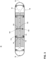
- FIG. 3 is a bottom view of an exemplary lifter of the laundry treating appliance of FIG. 1 according to aspects of the present disclosure.
- the lifter housing 50 can comprise one or more coupling elements 102 for receiving one or more coupling mechanisms located on the circumferential surface of the drum 28 to couple the lifter housing 50 to the drum 28.
- the coupling element 102 can comprise post-receiving elements 104 and 105 in a spaced apart relationship separated by a crosspiece 103 therebetween.
- Crosspiece 103 can be a structural support rib that provides bracing and/or rigidity to the lifter housing 50.
- Each of the post-receiving elements 104 and 105 can receive an opposing post (not shown) from the drum 28 to connect the lifter housing 50 to the drum 28 through a snap-fit connection and prevent forward to aft movement and shifting of the lifter 36 during operation of the washing machine 10
- coupling elements 102 can comprise any snap-fit mechanism, slide-lock mechanism, or other coupling means to connect the lifter housing 50 to the drum 28 without departing from the scope of the disclosure.
- the lifter housing 50 can further comprise one or more engagement elements 110 that can be coupled to an opposing receiver located on the circumferential surface of the drum 28 to connect the lifter housing 50 to the drum 28 and prevent side-to-side motion of the lifter 36 in the drum 28 during operation of the washing machine 10.
- the engagement elements 110 comprise P-shaped tabs 114 and 115 in a spaced apart relationship separated by a crosspiece 116 therebetween.
- Crosspiece 116 can be a structural support rib that provides bracing and/or rigidity to the lifter housing 50.
- Each P-shaped tab 114 and 115 can pilot into an opposing receiving slot (not shown) provided on the drum 28 to form a slide-lock connection to connect the lifter housing 50 to the drum 28 and prevent side-to-side movement and shifting of the lifter 36 during operation of the washing machine 10. While the illustration shows four sets (four on each side of the inner surface of each outer surface 56) of P-shaped tabs, more or fewer tabs could be used. Also, as should be recognized, other types of engagement elements 110 such as snap-fit or slide-lock mechanism could be used.
- FIG. 4 is an illustrative bar graph comparing the mean mechanical action (gentleness) score and mean total cleaning score of a traditional lifter vs. a lifter according to aspects of the present disclosure.
- the scores were generated by evaluations performed using the Association of Home Appliance Manufacturers Performance Evaluation Procedures for Household Clothes Washers (AHAM HLW-1-2013).
- Mechanical Action scores are indicative of how gentle a machine treats fabrics during a wash cycle.
- a lower mechanical action score indicates a higher 'gentleness' to the laundry.
- cleaning scores and gentleness on fabrics are inversely related such that as mechanical action rises, in turn, cleaning scores rise, and gentleness to the laundry drops.
- the lifter described herein can disrupt that inverse relationship by facilitating the same level of cleaning while increasing gentleness to the laundry by decreasing damage to the laundry through mechanical action.
- a bar graph 300 illustrates the mean mechanical action score of a lifter 305 according to aspects of the present disclosure vs. a traditional lifter 310.
- the lifter 305 has a mean mechanical action score of 54
- the traditional lifter 310 has a mean mechanical action score of 66, indicating that the lifter 305 is gentler to a laundry load than a traditional lifter 310.
- Bar graph 300 further illustrates the total cleaning score of the lifter 305 vs. the traditional lifter 310.
- the lifter 305 has a mean total cleaning score of 101.8 while the traditional lifter 310 has a mean total cleaning score of 102.5, illustrating that the total cleaning scores of the lifter 305 and the traditional lifter 310 are similar.
- the bar graph 300 illustrates that the lifter 305 and the traditional lifter 310 can have similar total cleaning scores, however, the lifter 305 is gentler on laundry as illustrated by the lower mean mechanical action score of the lifter 305.
- the laundry treating appliance as described herein wherein the drum further comprises an inner circumferential surface to which the lifter housing is secured.
- the laundry treating appliance as described herein further comprising at least one post connecting the lifter housing to the drum to prevent forward to aft motion of the lifter housing.
- the laundry treating appliance as described herein at least one tab connecting the lifter housing to the drum to prevent side-to-side motion of the lifter housing.
Landscapes
- Engineering & Computer Science (AREA)
- Textile Engineering (AREA)
- Main Body Construction Of Washing Machines And Laundry Dryers (AREA)
Description
- Laundry treating appliances, such as clothes washers, refreshers, and non-aqueous systems, can have a configuration based on a rotating drum that defines a treating chamber in which laundry items are placed for treating. The drum may include one or more lifters located along the inner surface of the drum. The lifters can facilitate movement and cleaning of the laundry within the drum as the drum rotates. Lifters can impart damage onto laundry items as they facilitate cleaning.
-
US 6 021 536 A discloses a mechanical desizing and abrading device having a rotating drum and abrading lifters. -
EP 2 546 403 A1 discloses a washing machine including a lifter housing carried by the drum. USD773763S discloses a washing machine according to the preamble of claim 1. -
CN 1 081 695 C discloses a washing machine including a lifter housing carried by the drum.GB 219 757 A US 1 389 182 A discloses a washing machine including a lifter housing carried by the drum. - The present invention relates to a laundry treating appliance according to independent claim 1.
- In the drawings:
-
FIG. 1 is a perspective of a laundry treating appliance in the form of a washing machine having a lifter according to aspects of the present disclosure. -
FIG. 2 is a perspective view of an exemplary lifter of the laundry treating appliance ofFIG. 1 according to aspects of the present disclosure. -
FIG. 3 is a bottom view of the lifter ofFIG. 2 according to aspects of the present disclosure. -
FIG. 4 is an illustrative bar graph comparing a mean mechanical action score and mean total cleaning score of a traditional lifter vs. a lifter according to aspects of the present disclosure. - Aspects of the present disclosure relate to a laundry treating appliance having a tub that contains an interior defining a liquid chamber, a rotatable drum within the liquid chamber and a lifter inside the drum that is configured to lift laundry in the drum by upward rotation of the drum.
- The lifter includes grooves that allow for the laundry treating appliance to obtain about the same cleaning scores as when using larger lifters while increasing the gentleness on the laundry according to evaluations performed using the Association of Home Appliance Manufacturers Performance Evaluation Procedures for Household Clothes Washers (AHAM HLW-1-2013). Typically, cleaning scores and gentleness are inversely related such that as cleaning scores rise, gentleness drops. The presence of the grooves on the lifter and its geometry allow for a smaller, lower profile lifter that can clean as well as a larger lifter, yet be gentler on laundry items.
- By way of overview,
FIG. 1 is an illustrative example of a laundry treating appliance that can be any appliance that performs a cycle of operation to clean or otherwise treat items placed therein. The laundry treating appliance is illustrated as a horizontalaxis washing machine 10, which can include acabinet 12 for housing the operational parts of the machine, together with a hingeddoor 18. Aconsole 21 having acontrol panel 20 which includes theoperating controls 22 for the washer is illustrated on the upper, front of thecabinet 12, but can be located elsewhere. Housed within thecabinet 12 is a wash tub supported by a suitable suspension system. Adrum 28 can be provided within the tub and defines at least a portion of a treating chamber 30 in which the laundry is treated. Thedrum 28, located within the liquid chamber, can generally rotate about a horizontal axis and holds the laundry during operation of thewashing machine 10. Thedrum 28 may include a plurality ofperforations 32 such that liquid may flow between the tub and thedrum 28 through theperforations 32. Thedrum 28 comprises an inner circumferential surface to which one ormore lifters 36 can be secured. Thelifters 36 lift the laundry load received in the treating chamber 30 by upward rotation of thedrum 28. - Conventional washing machine components are not described in detail, but are described briefly as needed to provide an illustrative environment to support a complete understanding of aspects of the present disclosure.
- Referring to
FIG. 2 as an illustrative example of a lifter of the laundry treating appliance ofFIG. 1 according to aspects of the present disclosure, thelifter 36 can comprise alifter housing 50 carried by thedrum 28 during rotation of thedrum 28. Thelifter housing 50 comprises anelongated body 52 andopposing end elements drain holes 55 to allow for any wash liquid that could accumulate inside thelifter housing 50 during a cycle of operation to be expelled or drained from thelifter housing 50. Thelifter housing 50 can comprise plastic, such as polypropylene, stainless steel, or any other suitable material that can withstand the interior conditions of the liquid chamber of a laundry treating appliance such aswashing machine 10. - The
elongated body 52 comprises a pair of spaced apartouter surfaces 56 that form the sides along the length of theelongated body 52. The pair ofouter surfaces 56 can be angled toward each other and coupled together by atop 60. Theopposing end elements outer surfaces 56 and thetop 60 of theelongated body 52 to define thelifter housing 50. While the illustration shows theelongated body 52 having a symmetrical cross-section relative to its longitudinal axis, thebody 52 could be formed withouter surfaces 56 having different widths, thus creating an unequal or asymmetrical cross-section. - In one aspect of the present disclosure, the
outer surfaces 56 can be straight while thetop 60 is rounded such that the cross-section of theelongated body 52 relative to its longitudinal axis is generally triangular in shape. In another aspect of the present disclosure, theouter surfaces 56 can be straight while thetop 60 is substantially square such that the cross-section of theelongated body 52 relative to its longitudinal axis is mostly triangular in shape with a substantially squared-off apex. It should be recognized that theouter surfaces 56 could also by slightly concave or convex, or a combination thereof, without departing from the scope of the disclosure. Furthermore, theopposing end elements drum 28. - The
outer surface 56 can comprise a plurality of uniformly spaced apartgrooves 68 that extend longitudinally along theelongated body 52. Thegrooves 68 can be arranged in parallel along the length of theelongated body 52 such that a space between onegroove 68 and thenext groove 68 defines awidth 70 that is substantially proportional to an interior width 72 of thegroove 68 itself. Thegrooves 68 can have a concave shape, such as a U-shaped, interior section and can comprise a curved or straight end at one or both of their terminal longitudinal lengths. Alternatively, thegrooves 68 can comprise a less annular shape, such as a V-shape or rectangular cross-sectional shape, in the interior section. Thewidth 70 between each groove is flat and uniform and can be more than, less than, or equal to the interior width 72 of thegroove 68. -
FIG. 3 is a bottom view of an exemplary lifter of the laundry treating appliance ofFIG. 1 according to aspects of the present disclosure. Thelifter housing 50 can comprise one ormore coupling elements 102 for receiving one or more coupling mechanisms located on the circumferential surface of thedrum 28 to couple thelifter housing 50 to thedrum 28. In more detail, thecoupling element 102 can comprisepost-receiving elements crosspiece 103 therebetween. Crosspiece 103 can be a structural support rib that provides bracing and/or rigidity to thelifter housing 50. Each of thepost-receiving elements drum 28 to connect thelifter housing 50 to thedrum 28 through a snap-fit connection and prevent forward to aft movement and shifting of thelifter 36 during operation of thewashing machine 10 It should be recognized thatcoupling elements 102 can comprise any snap-fit mechanism, slide-lock mechanism, or other coupling means to connect thelifter housing 50 to thedrum 28 without departing from the scope of the disclosure. - The
lifter housing 50 can further comprise one ormore engagement elements 110 that can be coupled to an opposing receiver located on the circumferential surface of thedrum 28 to connect thelifter housing 50 to thedrum 28 and prevent side-to-side motion of thelifter 36 in thedrum 28 during operation of thewashing machine 10. In more detail, theengagement elements 110 comprise P-shaped tabs crosspiece 116 therebetween. Crosspiece 116 can be a structural support rib that provides bracing and/or rigidity to thelifter housing 50. Each P-shaped tab drum 28 to form a slide-lock connection to connect thelifter housing 50 to thedrum 28 and prevent side-to-side movement and shifting of thelifter 36 during operation of thewashing machine 10. While the illustration shows four sets (four on each side of the inner surface of each outer surface 56) of P-shaped tabs, more or fewer tabs could be used. Also, as should be recognized, other types ofengagement elements 110 such as snap-fit or slide-lock mechanism could be used. - Benefits of aspects described herein can include a smaller, lower profile lifter that is gentler on laundry yet can clean laundry as well as a traditional, larger, more fabric damaging lifter configuration.
FIG. 4 is an illustrative bar graph comparing the mean mechanical action (gentleness) score and mean total cleaning score of a traditional lifter vs. a lifter according to aspects of the present disclosure. The scores were generated by evaluations performed using the Association of Home Appliance Manufacturers Performance Evaluation Procedures for Household Clothes Washers (AHAM HLW-1-2013). Mechanical Action scores are indicative of how gentle a machine treats fabrics during a wash cycle. In aspects of the present disclosure, a lower mechanical action score indicates a higher 'gentleness' to the laundry. Typically, cleaning scores and gentleness on fabrics are inversely related such that as mechanical action rises, in turn, cleaning scores rise, and gentleness to the laundry drops. The lifter described herein can disrupt that inverse relationship by facilitating the same level of cleaning while increasing gentleness to the laundry by decreasing damage to the laundry through mechanical action. - In
FIG. 4 , abar graph 300 illustrates the mean mechanical action score of alifter 305 according to aspects of the present disclosure vs. atraditional lifter 310. In thebar graph 300, thelifter 305 has a mean mechanical action score of 54, while thetraditional lifter 310 has a mean mechanical action score of 66, indicating that thelifter 305 is gentler to a laundry load than atraditional lifter 310.Bar graph 300 further illustrates the total cleaning score of thelifter 305 vs. thetraditional lifter 310. In thebar graph 300, thelifter 305 has a mean total cleaning score of 101.8 while thetraditional lifter 310 has a mean total cleaning score of 102.5, illustrating that the total cleaning scores of thelifter 305 and thetraditional lifter 310 are similar. Thebar graph 300 illustrates that thelifter 305 and thetraditional lifter 310 can have similar total cleaning scores, however, thelifter 305 is gentler on laundry as illustrated by the lower mean mechanical action score of thelifter 305. - It is intended that the following concepts can define at least a portion of the scope of the disclosure and that the apparatus and/or method(s) within the scope of these concepts and their equivalents be covered thereby. This disclosure should be understood to include all novel and non-obvious combinations of elements described herein, and the concepts may be presented in this or a later application to any novel and non-obvious combination of these elements. Any aspect of any embodiment can be combined with any aspect of any other embodiments. Moreover, the foregoing embodiments are illustrative, and no single feature or element is essential to all possible combinations that may be included in this or a later application. For example, other inventions arising from this disclosure may include any combination of the following concepts:
- The laundry treating appliance as described herein wherein the drum further comprises an inner circumferential surface to which the lifter housing is secured.
- The laundry treating appliance as described herein further comprising at least one post connecting the lifter housing to the drum to prevent forward to aft motion of the lifter housing.
- The laundry treating appliance as described herein at least one tab connecting the lifter housing to the drum to prevent side-to-side motion of the lifter housing.
- The laundry treating appliance as described herein wherein the at least one tab snap fits in to an opposing receiver in the drum.
- While the invention has been specifically described in connection with certain specific embodiments thereof, it is to be understood that this is by way of illustration and not of limitation. Reasonable variation and modification are possible within the scope of the forgoing disclosure and drawings without departing from the invention which is defined in the appended claims.
Claims (14)
- A laundry washing machine (10), comprising:a tub having a tub interior defining a liquid chamber;a rotatable drum (28) located within the liquid chamber and rotatable about a rotational axis, and at least partially defining a treating chamber (30); anda lifter housing (50) carried by the drum (28) comprising an elongated body (52) having an outer surface (56) and located within the treating chamber (30),characterized in thatthe outer surface (56) has a plurality of spaced grooves (68) extending longitudinally along the length of elongated body (52) and having a flat and uniform width (70) between each groove (68), said width (70) being defined by the space between one groove (68) and the next groove (68) in the direction from one groove to the next groove,said grooves having a concave U-shaped interior section dug inwards the interior of the lifter housing.
- The laundry washing machine (10) of claim 1 wherein the drum (28) further comprises an inner circumferential surface to which the lifter housing (50) is secured.
- The laundry washing machine (10) of claim 1-2 further comprising at least one post connecting the lifter housing (50) to the drum (28) to prevent forward to aft motion of the lifter housing (50).
- The laundry washing machine (10) of claim 3 wherein the at least one post snap fits in to an opposing post-receiving element (104, 105) on the lifter housing (50).
- The laundry washing machine (10) of claim 1-2 further comprising at least one tab (114, 115) connecting the lifter housing (50) to the drum (28) to prevent side-to-side motion of the lifter housing (50).
- The laundry washing machine (10) of claim 5 wherein the at least one tab (114, 115) snap fits in to an opposing receiver in the drum (28).
- The laundry washing machine (10) according to any of the preceding claims wherein at least some of the spaced grooves (68) are parallel.
- The laundry washing machine (10) according to any of the preceding claims wherein the body (52) has a triangular cross section.
- The laundry washing machine (10) of claim 8 wherein the elongated body (52) has a symmetrical cross-section relative to a longitudinal axis of the elongated body (52).
- The laundry washing machine (10) of claim 9 wherein the outer surface (56) is one of straight or concave.
- The laundry washing machine (10) according to any of the preceding claims where the lifter housing (50) comprises plastic or stainless steel.
- The laundry washing machine (10) according to claim 1, comprising:
a lifter (36) secured to the drum (28) and adapted to lift the laundry in the drum (28) by upward rotation of the drum (28), wherein the lifter (36) comprises:
the lifter housing (50) having the at least one outer surface (56) with a plurality of uniformly spaced grooves (68) along a length of the lifter (36) and defining a width (70) between each groove (68); wherein the width (70) between each groove (68) is less than the width of adjacent grooves (68). - The laundry washing machine (10) according to any of the preceding claims wherein a pair of outer surfaces (56) defines the lifter housing (50) and wherein the pair of outer surfaces (56) are spaced apart and angled toward each other.
- The laundry washing machine (10) of claim 13 further comprising a rounded top (60) coupling the pair of outer surfaces (56).
Applications Claiming Priority (1)
| Application Number | Priority Date | Filing Date | Title |
|---|---|---|---|
| US15/719,682 US10648116B2 (en) | 2017-09-29 | 2017-09-29 | Laundry treating appliance lifter |
Publications (2)
| Publication Number | Publication Date |
|---|---|
| EP3461941A1 EP3461941A1 (en) | 2019-04-03 |
| EP3461941B1 true EP3461941B1 (en) | 2023-03-29 |
Family
ID=63713674
Family Applications (1)
| Application Number | Title | Priority Date | Filing Date |
|---|---|---|---|
| EP18197617.6A Active EP3461941B1 (en) | 2017-09-29 | 2018-09-28 | Laundry treating appliance lifter |
Country Status (2)
| Country | Link |
|---|---|
| US (1) | US10648116B2 (en) |
| EP (1) | EP3461941B1 (en) |
Families Citing this family (3)
| Publication number | Priority date | Publication date | Assignee | Title |
|---|---|---|---|---|
| EP3690110B1 (en) | 2019-02-01 | 2021-06-02 | LG Electronics Inc. | Laundry treating apparatus |
| KR102422407B1 (en) * | 2020-03-06 | 2022-07-18 | 엘지전자 주식회사 | Laundry treating apparatus |
| CN112663285B (en) * | 2020-12-29 | 2025-09-23 | 珠海格力电器股份有限公司 | A lifting rib module for a drum and a washing machine having the same |
Citations (5)
| Publication number | Priority date | Publication date | Assignee | Title |
|---|---|---|---|---|
| US1389182A (en) * | 1920-03-31 | 1921-08-30 | Binder Gottlob | Rotary washing-machine |
| GB219757A (en) * | 1923-05-09 | 1924-08-07 | William Litler Bradford | Improvements in machines for washing, boiling and rinsing clothes or similar articles |
| CN1081695C (en) * | 1996-02-15 | 2002-03-27 | 松下电器产业株式会社 | Washing machine |
| US20050204783A1 (en) * | 2004-03-19 | 2005-09-22 | Lg Electronics Inc. | Drum-type washing machine |
| USD773763S1 (en) * | 2015-02-24 | 2016-12-06 | Samsung Electronics Co., Ltd. | Drum lifter for drum washing machine |
Family Cites Families (9)
| Publication number | Priority date | Publication date | Assignee | Title |
|---|---|---|---|---|
| FR1535336A (en) | 1966-08-31 | 1968-08-02 | Philips Nv | Improvement of washing machines for domestic use |
| US5115651A (en) | 1989-10-05 | 1992-05-26 | Sanyo Electric Co., Ltd. | Drum-type washing machine |
| US6021536A (en) | 1993-03-04 | 2000-02-08 | Wasinger; Eric | Mechanical desizing and abrading device |
| KR20070119321A (en) * | 2006-06-15 | 2007-12-20 | 엘지전자 주식회사 | Washing machine with drum lifter and drum forming method |
| JP5147088B2 (en) | 2010-07-27 | 2013-02-20 | 株式会社ハッピー | Washing machine |
| KR20120082968A (en) | 2011-01-16 | 2012-07-25 | 삼성전자주식회사 | Washing machine and pulsator thereof |
| EP2546403A1 (en) | 2011-07-14 | 2013-01-16 | Electrolux Home Products Corporation N.V. | Drum washing machine |
| KR20130034911A (en) * | 2011-09-29 | 2013-04-08 | 삼성전자주식회사 | Lifter and washing machine having the same |
| KR101504093B1 (en) * | 2013-07-04 | 2015-03-19 | 동부대우전자 주식회사 | Drum type washing machine |
-
2017
- 2017-09-29 US US15/719,682 patent/US10648116B2/en active Active
-
2018
- 2018-09-28 EP EP18197617.6A patent/EP3461941B1/en active Active
Patent Citations (5)
| Publication number | Priority date | Publication date | Assignee | Title |
|---|---|---|---|---|
| US1389182A (en) * | 1920-03-31 | 1921-08-30 | Binder Gottlob | Rotary washing-machine |
| GB219757A (en) * | 1923-05-09 | 1924-08-07 | William Litler Bradford | Improvements in machines for washing, boiling and rinsing clothes or similar articles |
| CN1081695C (en) * | 1996-02-15 | 2002-03-27 | 松下电器产业株式会社 | Washing machine |
| US20050204783A1 (en) * | 2004-03-19 | 2005-09-22 | Lg Electronics Inc. | Drum-type washing machine |
| USD773763S1 (en) * | 2015-02-24 | 2016-12-06 | Samsung Electronics Co., Ltd. | Drum lifter for drum washing machine |
Also Published As
| Publication number | Publication date |
|---|---|
| US20190100865A1 (en) | 2019-04-04 |
| US10648116B2 (en) | 2020-05-12 |
| EP3461941A1 (en) | 2019-04-03 |
Similar Documents
| Publication | Publication Date | Title |
|---|---|---|
| EP2719808B1 (en) | Washing machine | |
| US9010159B2 (en) | Laundry treating appliance with tub ring | |
| EP1970478B1 (en) | Washing machine and control method for disentangling clothes in the washing machine | |
| US9115452B2 (en) | Laundry treating appliance impeller | |
| EP2372010B1 (en) | Rotatable drum for laundry washing machines and assembly method of the rotatable drum | |
| EP3461941A1 (en) | Laundry treating appliance lifter | |
| EP2546403A1 (en) | Drum washing machine | |
| EP2815016B1 (en) | Laundry treating apparatus | |
| KR20130034911A (en) | Lifter and washing machine having the same | |
| EP3279388B1 (en) | Clothes treating apparatus | |
| US10655262B2 (en) | Laundry treating appliance with a tub ring | |
| EP3401433A1 (en) | Clothes treating apparatus | |
| CN110691874B (en) | Laundry treating apparatus and control method thereof | |
| US10036113B2 (en) | Laundry treating appliance with embossed container | |
| KR20130095604A (en) | Washing machine | |
| EP2832916B1 (en) | Laundry treating machine including a rotatable drum | |
| CN110741118A (en) | Laundry treating apparatus and control method thereof | |
| KR102148193B1 (en) | Washing Machine | |
| US9115458B2 (en) | Washer/dryer | |
| EP3334320B1 (en) | A household appliance comprising a knob mounted to the control panel | |
| KR20000013771U (en) | Drum of Washing Machine |
Legal Events
| Date | Code | Title | Description |
|---|---|---|---|
| PUAI | Public reference made under article 153(3) epc to a published international application that has entered the european phase |
Free format text: ORIGINAL CODE: 0009012 |
|
| STAA | Information on the status of an ep patent application or granted ep patent |
Free format text: STATUS: THE APPLICATION HAS BEEN PUBLISHED |
|
| AK | Designated contracting states |
Kind code of ref document: A1 Designated state(s): AL AT BE BG CH CY CZ DE DK EE ES FI FR GB GR HR HU IE IS IT LI LT LU LV MC MK MT NL NO PL PT RO RS SE SI SK SM TR |
|
| AX | Request for extension of the european patent |
Extension state: BA ME |
|
| STAA | Information on the status of an ep patent application or granted ep patent |
Free format text: STATUS: REQUEST FOR EXAMINATION WAS MADE |
|
| 17P | Request for examination filed |
Effective date: 20190924 |
|
| RBV | Designated contracting states (corrected) |
Designated state(s): AL AT BE BG CH CY CZ DE DK EE ES FI FR GB GR HR HU IE IS IT LI LT LU LV MC MK MT NL NO PL PT RO RS SE SI SK SM TR |
|
| STAA | Information on the status of an ep patent application or granted ep patent |
Free format text: STATUS: EXAMINATION IS IN PROGRESS |
|
| 17Q | First examination report despatched |
Effective date: 20200117 |
|
| GRAP | Despatch of communication of intention to grant a patent |
Free format text: ORIGINAL CODE: EPIDOSNIGR1 |
|
| STAA | Information on the status of an ep patent application or granted ep patent |
Free format text: STATUS: GRANT OF PATENT IS INTENDED |
|
| GRAS | Grant fee paid |
Free format text: ORIGINAL CODE: EPIDOSNIGR3 |
|
| INTG | Intention to grant announced |
Effective date: 20230126 |
|
| GRAA | (expected) grant |
Free format text: ORIGINAL CODE: 0009210 |
|
| STAA | Information on the status of an ep patent application or granted ep patent |
Free format text: STATUS: THE PATENT HAS BEEN GRANTED |
|
| AK | Designated contracting states |
Kind code of ref document: B1 Designated state(s): AL AT BE BG CH CY CZ DE DK EE ES FI FR GB GR HR HU IE IS IT LI LT LU LV MC MK MT NL NO PL PT RO RS SE SI SK SM TR |
|
| REG | Reference to a national code |
Ref country code: CH Ref legal event code: EP |
|
| REG | Reference to a national code |
Ref country code: DE Ref legal event code: R096 Ref document number: 602018047698 Country of ref document: DE |
|
| REG | Reference to a national code |
Ref country code: AT Ref legal event code: REF Ref document number: 1556724 Country of ref document: AT Kind code of ref document: T Effective date: 20230415 |
|
| REG | Reference to a national code |
Ref country code: IE Ref legal event code: FG4D |
|
| REG | Reference to a national code |
Ref country code: LT Ref legal event code: MG9D |
|
| P01 | Opt-out of the competence of the unified patent court (upc) registered |
Effective date: 20230530 |
|
| PG25 | Lapsed in a contracting state [announced via postgrant information from national office to epo] |
Ref country code: RS Free format text: LAPSE BECAUSE OF FAILURE TO SUBMIT A TRANSLATION OF THE DESCRIPTION OR TO PAY THE FEE WITHIN THE PRESCRIBED TIME-LIMIT Effective date: 20230329 Ref country code: NO Free format text: LAPSE BECAUSE OF FAILURE TO SUBMIT A TRANSLATION OF THE DESCRIPTION OR TO PAY THE FEE WITHIN THE PRESCRIBED TIME-LIMIT Effective date: 20230629 Ref country code: LV Free format text: LAPSE BECAUSE OF FAILURE TO SUBMIT A TRANSLATION OF THE DESCRIPTION OR TO PAY THE FEE WITHIN THE PRESCRIBED TIME-LIMIT Effective date: 20230329 Ref country code: LT Free format text: LAPSE BECAUSE OF FAILURE TO SUBMIT A TRANSLATION OF THE DESCRIPTION OR TO PAY THE FEE WITHIN THE PRESCRIBED TIME-LIMIT Effective date: 20230329 Ref country code: HR Free format text: LAPSE BECAUSE OF FAILURE TO SUBMIT A TRANSLATION OF THE DESCRIPTION OR TO PAY THE FEE WITHIN THE PRESCRIBED TIME-LIMIT Effective date: 20230329 |
|
| REG | Reference to a national code |
Ref country code: NL Ref legal event code: MP Effective date: 20230329 |
|
| REG | Reference to a national code |
Ref country code: AT Ref legal event code: MK05 Ref document number: 1556724 Country of ref document: AT Kind code of ref document: T Effective date: 20230329 |
|
| PG25 | Lapsed in a contracting state [announced via postgrant information from national office to epo] |
Ref country code: SE Free format text: LAPSE BECAUSE OF FAILURE TO SUBMIT A TRANSLATION OF THE DESCRIPTION OR TO PAY THE FEE WITHIN THE PRESCRIBED TIME-LIMIT Effective date: 20230329 Ref country code: NL Free format text: LAPSE BECAUSE OF FAILURE TO SUBMIT A TRANSLATION OF THE DESCRIPTION OR TO PAY THE FEE WITHIN THE PRESCRIBED TIME-LIMIT Effective date: 20230329 Ref country code: GR Free format text: LAPSE BECAUSE OF FAILURE TO SUBMIT A TRANSLATION OF THE DESCRIPTION OR TO PAY THE FEE WITHIN THE PRESCRIBED TIME-LIMIT Effective date: 20230630 Ref country code: FI Free format text: LAPSE BECAUSE OF FAILURE TO SUBMIT A TRANSLATION OF THE DESCRIPTION OR TO PAY THE FEE WITHIN THE PRESCRIBED TIME-LIMIT Effective date: 20230329 |
|
| PG25 | Lapsed in a contracting state [announced via postgrant information from national office to epo] |
Ref country code: SM Free format text: LAPSE BECAUSE OF FAILURE TO SUBMIT A TRANSLATION OF THE DESCRIPTION OR TO PAY THE FEE WITHIN THE PRESCRIBED TIME-LIMIT Effective date: 20230329 Ref country code: RO Free format text: LAPSE BECAUSE OF FAILURE TO SUBMIT A TRANSLATION OF THE DESCRIPTION OR TO PAY THE FEE WITHIN THE PRESCRIBED TIME-LIMIT Effective date: 20230329 Ref country code: PT Free format text: LAPSE BECAUSE OF FAILURE TO SUBMIT A TRANSLATION OF THE DESCRIPTION OR TO PAY THE FEE WITHIN THE PRESCRIBED TIME-LIMIT Effective date: 20230731 Ref country code: ES Free format text: LAPSE BECAUSE OF FAILURE TO SUBMIT A TRANSLATION OF THE DESCRIPTION OR TO PAY THE FEE WITHIN THE PRESCRIBED TIME-LIMIT Effective date: 20230329 Ref country code: EE Free format text: LAPSE BECAUSE OF FAILURE TO SUBMIT A TRANSLATION OF THE DESCRIPTION OR TO PAY THE FEE WITHIN THE PRESCRIBED TIME-LIMIT Effective date: 20230329 Ref country code: AT Free format text: LAPSE BECAUSE OF FAILURE TO SUBMIT A TRANSLATION OF THE DESCRIPTION OR TO PAY THE FEE WITHIN THE PRESCRIBED TIME-LIMIT Effective date: 20230329 |
|
| PGFP | Annual fee paid to national office [announced via postgrant information from national office to epo] |
Ref country code: IT Payment date: 20230920 Year of fee payment: 6 Ref country code: GB Payment date: 20230926 Year of fee payment: 6 |
|
| PG25 | Lapsed in a contracting state [announced via postgrant information from national office to epo] |
Ref country code: SK Free format text: LAPSE BECAUSE OF FAILURE TO SUBMIT A TRANSLATION OF THE DESCRIPTION OR TO PAY THE FEE WITHIN THE PRESCRIBED TIME-LIMIT Effective date: 20230329 Ref country code: PL Free format text: LAPSE BECAUSE OF FAILURE TO SUBMIT A TRANSLATION OF THE DESCRIPTION OR TO PAY THE FEE WITHIN THE PRESCRIBED TIME-LIMIT Effective date: 20230329 Ref country code: IS Free format text: LAPSE BECAUSE OF FAILURE TO SUBMIT A TRANSLATION OF THE DESCRIPTION OR TO PAY THE FEE WITHIN THE PRESCRIBED TIME-LIMIT Effective date: 20230729 |
|
| PGFP | Annual fee paid to national office [announced via postgrant information from national office to epo] |
Ref country code: FR Payment date: 20230926 Year of fee payment: 6 Ref country code: DE Payment date: 20230928 Year of fee payment: 6 |
|
| REG | Reference to a national code |
Ref country code: DE Ref legal event code: R097 Ref document number: 602018047698 Country of ref document: DE |
|
| PG25 | Lapsed in a contracting state [announced via postgrant information from national office to epo] |
Ref country code: DK Free format text: LAPSE BECAUSE OF FAILURE TO SUBMIT A TRANSLATION OF THE DESCRIPTION OR TO PAY THE FEE WITHIN THE PRESCRIBED TIME-LIMIT Effective date: 20230329 Ref country code: CZ Free format text: LAPSE BECAUSE OF FAILURE TO SUBMIT A TRANSLATION OF THE DESCRIPTION OR TO PAY THE FEE WITHIN THE PRESCRIBED TIME-LIMIT Effective date: 20230329 |
|
| PLBE | No opposition filed within time limit |
Free format text: ORIGINAL CODE: 0009261 |
|
| STAA | Information on the status of an ep patent application or granted ep patent |
Free format text: STATUS: NO OPPOSITION FILED WITHIN TIME LIMIT |
|
| 26N | No opposition filed |
Effective date: 20240103 |
|
| REG | Reference to a national code |
Ref country code: CH Ref legal event code: PL |
|
| PG25 | Lapsed in a contracting state [announced via postgrant information from national office to epo] |
Ref country code: SI Free format text: LAPSE BECAUSE OF FAILURE TO SUBMIT A TRANSLATION OF THE DESCRIPTION OR TO PAY THE FEE WITHIN THE PRESCRIBED TIME-LIMIT Effective date: 20230329 |
|
| PG25 | Lapsed in a contracting state [announced via postgrant information from national office to epo] |
Ref country code: LU Free format text: LAPSE BECAUSE OF NON-PAYMENT OF DUE FEES Effective date: 20230928 |
|
| REG | Reference to a national code |
Ref country code: BE Ref legal event code: MM Effective date: 20230930 |
|
| PG25 | Lapsed in a contracting state [announced via postgrant information from national office to epo] |
Ref country code: SI Free format text: LAPSE BECAUSE OF FAILURE TO SUBMIT A TRANSLATION OF THE DESCRIPTION OR TO PAY THE FEE WITHIN THE PRESCRIBED TIME-LIMIT Effective date: 20230329 Ref country code: LU Free format text: LAPSE BECAUSE OF NON-PAYMENT OF DUE FEES Effective date: 20230928 Ref country code: MC Free format text: LAPSE BECAUSE OF FAILURE TO SUBMIT A TRANSLATION OF THE DESCRIPTION OR TO PAY THE FEE WITHIN THE PRESCRIBED TIME-LIMIT Effective date: 20230329 |
|
| REG | Reference to a national code |
Ref country code: IE Ref legal event code: MM4A |
|
| PG25 | Lapsed in a contracting state [announced via postgrant information from national office to epo] |
Ref country code: IE Free format text: LAPSE BECAUSE OF NON-PAYMENT OF DUE FEES Effective date: 20230928 |
|
| PG25 | Lapsed in a contracting state [announced via postgrant information from national office to epo] |
Ref country code: CH Free format text: LAPSE BECAUSE OF NON-PAYMENT OF DUE FEES Effective date: 20230930 |
|
| PG25 | Lapsed in a contracting state [announced via postgrant information from national office to epo] |
Ref country code: IE Free format text: LAPSE BECAUSE OF NON-PAYMENT OF DUE FEES Effective date: 20230928 Ref country code: CH Free format text: LAPSE BECAUSE OF NON-PAYMENT OF DUE FEES Effective date: 20230930 |
|
| PG25 | Lapsed in a contracting state [announced via postgrant information from national office to epo] |
Ref country code: BE Free format text: LAPSE BECAUSE OF NON-PAYMENT OF DUE FEES Effective date: 20230930 |
|
| PG25 | Lapsed in a contracting state [announced via postgrant information from national office to epo] |
Ref country code: BG Free format text: LAPSE BECAUSE OF FAILURE TO SUBMIT A TRANSLATION OF THE DESCRIPTION OR TO PAY THE FEE WITHIN THE PRESCRIBED TIME-LIMIT Effective date: 20230329 |
|
| PG25 | Lapsed in a contracting state [announced via postgrant information from national office to epo] |
Ref country code: BG Free format text: LAPSE BECAUSE OF FAILURE TO SUBMIT A TRANSLATION OF THE DESCRIPTION OR TO PAY THE FEE WITHIN THE PRESCRIBED TIME-LIMIT Effective date: 20230329 |
|
| REG | Reference to a national code |
Ref country code: DE Ref legal event code: R119 Ref document number: 602018047698 Country of ref document: DE |
|
| GBPC | Gb: european patent ceased through non-payment of renewal fee |
Effective date: 20240928 |
|
| PG25 | Lapsed in a contracting state [announced via postgrant information from national office to epo] |
Ref country code: DE Free format text: LAPSE BECAUSE OF NON-PAYMENT OF DUE FEES Effective date: 20250401 |
|
| PG25 | Lapsed in a contracting state [announced via postgrant information from national office to epo] |
Ref country code: GB Free format text: LAPSE BECAUSE OF NON-PAYMENT OF DUE FEES Effective date: 20240928 |
|
| PG25 | Lapsed in a contracting state [announced via postgrant information from national office to epo] |
Ref country code: IT Free format text: LAPSE BECAUSE OF NON-PAYMENT OF DUE FEES Effective date: 20240928 |
|
| PG25 | Lapsed in a contracting state [announced via postgrant information from national office to epo] |
Ref country code: FR Free format text: LAPSE BECAUSE OF NON-PAYMENT OF DUE FEES Effective date: 20240930 |
|
| PG25 | Lapsed in a contracting state [announced via postgrant information from national office to epo] |
Ref country code: CY Free format text: LAPSE BECAUSE OF FAILURE TO SUBMIT A TRANSLATION OF THE DESCRIPTION OR TO PAY THE FEE WITHIN THE PRESCRIBED TIME-LIMIT; INVALID AB INITIO Effective date: 20180928 |
|
| PG25 | Lapsed in a contracting state [announced via postgrant information from national office to epo] |
Ref country code: HU Free format text: LAPSE BECAUSE OF FAILURE TO SUBMIT A TRANSLATION OF THE DESCRIPTION OR TO PAY THE FEE WITHIN THE PRESCRIBED TIME-LIMIT; INVALID AB INITIO Effective date: 20180928 |
|
| PG25 | Lapsed in a contracting state [announced via postgrant information from national office to epo] |
Ref country code: TR Free format text: LAPSE BECAUSE OF FAILURE TO SUBMIT A TRANSLATION OF THE DESCRIPTION OR TO PAY THE FEE WITHIN THE PRESCRIBED TIME-LIMIT Effective date: 20230329 |