EP3461781A1 - Tension device for drive chain, method and escalator system using same - Google Patents
Tension device for drive chain, method and escalator system using same Download PDFInfo
- Publication number
- EP3461781A1 EP3461781A1 EP18192058.8A EP18192058A EP3461781A1 EP 3461781 A1 EP3461781 A1 EP 3461781A1 EP 18192058 A EP18192058 A EP 18192058A EP 3461781 A1 EP3461781 A1 EP 3461781A1
- Authority
- EP
- European Patent Office
- Prior art keywords
- drive chain
- spring
- tension device
- connecting rod
- supporting
- Prior art date
- Legal status (The legal status is an assumption and is not a legal conclusion. Google has not performed a legal analysis and makes no representation as to the accuracy of the status listed.)
- Granted
Links
Images



Classifications
-
- B—PERFORMING OPERATIONS; TRANSPORTING
- B66—HOISTING; LIFTING; HAULING
- B66B—ELEVATORS; ESCALATORS OR MOVING WALKWAYS
- B66B23/00—Component parts of escalators or moving walkways
- B66B23/16—Means allowing tensioning of the endless member
-
- B—PERFORMING OPERATIONS; TRANSPORTING
- B66—HOISTING; LIFTING; HAULING
- B66B—ELEVATORS; ESCALATORS OR MOVING WALKWAYS
- B66B23/00—Component parts of escalators or moving walkways
- B66B23/02—Driving gear
- B66B23/04—Driving gear for handrails
-
- B—PERFORMING OPERATIONS; TRANSPORTING
- B66—HOISTING; LIFTING; HAULING
- B66B—ELEVATORS; ESCALATORS OR MOVING WALKWAYS
- B66B23/00—Component parts of escalators or moving walkways
- B66B23/16—Means allowing tensioning of the endless member
- B66B23/20—Means allowing tensioning of the endless member for handrails
-
- F—MECHANICAL ENGINEERING; LIGHTING; HEATING; WEAPONS; BLASTING
- F16—ENGINEERING ELEMENTS AND UNITS; GENERAL MEASURES FOR PRODUCING AND MAINTAINING EFFECTIVE FUNCTIONING OF MACHINES OR INSTALLATIONS; THERMAL INSULATION IN GENERAL
- F16H—GEARING
- F16H7/00—Gearings for conveying rotary motion by endless flexible members
- F16H7/06—Gearings for conveying rotary motion by endless flexible members with chains
-
- F—MECHANICAL ENGINEERING; LIGHTING; HEATING; WEAPONS; BLASTING
- F16—ENGINEERING ELEMENTS AND UNITS; GENERAL MEASURES FOR PRODUCING AND MAINTAINING EFFECTIVE FUNCTIONING OF MACHINES OR INSTALLATIONS; THERMAL INSULATION IN GENERAL
- F16H—GEARING
- F16H7/00—Gearings for conveying rotary motion by endless flexible members
- F16H7/08—Means for varying tension of belts, ropes or chains
-
- F—MECHANICAL ENGINEERING; LIGHTING; HEATING; WEAPONS; BLASTING
- F16—ENGINEERING ELEMENTS AND UNITS; GENERAL MEASURES FOR PRODUCING AND MAINTAINING EFFECTIVE FUNCTIONING OF MACHINES OR INSTALLATIONS; THERMAL INSULATION IN GENERAL
- F16H—GEARING
- F16H7/00—Gearings for conveying rotary motion by endless flexible members
- F16H7/18—Means for guiding or supporting belts, ropes, or chains
-
- F—MECHANICAL ENGINEERING; LIGHTING; HEATING; WEAPONS; BLASTING
- F16—ENGINEERING ELEMENTS AND UNITS; GENERAL MEASURES FOR PRODUCING AND MAINTAINING EFFECTIVE FUNCTIONING OF MACHINES OR INSTALLATIONS; THERMAL INSULATION IN GENERAL
- F16H—GEARING
- F16H7/00—Gearings for conveying rotary motion by endless flexible members
- F16H7/08—Means for varying tension of belts, ropes or chains
- F16H2007/0802—Actuators for final output members
- F16H2007/0806—Compression coil springs
-
- F—MECHANICAL ENGINEERING; LIGHTING; HEATING; WEAPONS; BLASTING
- F16—ENGINEERING ELEMENTS AND UNITS; GENERAL MEASURES FOR PRODUCING AND MAINTAINING EFFECTIVE FUNCTIONING OF MACHINES OR INSTALLATIONS; THERMAL INSULATION IN GENERAL
- F16H—GEARING
- F16H7/00—Gearings for conveying rotary motion by endless flexible members
- F16H7/08—Means for varying tension of belts, ropes or chains
- F16H2007/0802—Actuators for final output members
- F16H2007/0821—Actuators for final output members working with gravity
-
- F—MECHANICAL ENGINEERING; LIGHTING; HEATING; WEAPONS; BLASTING
- F16—ENGINEERING ELEMENTS AND UNITS; GENERAL MEASURES FOR PRODUCING AND MAINTAINING EFFECTIVE FUNCTIONING OF MACHINES OR INSTALLATIONS; THERMAL INSULATION IN GENERAL
- F16H—GEARING
- F16H7/00—Gearings for conveying rotary motion by endless flexible members
- F16H7/08—Means for varying tension of belts, ropes or chains
- F16H2007/0842—Mounting or support of tensioner
-
- F—MECHANICAL ENGINEERING; LIGHTING; HEATING; WEAPONS; BLASTING
- F16—ENGINEERING ELEMENTS AND UNITS; GENERAL MEASURES FOR PRODUCING AND MAINTAINING EFFECTIVE FUNCTIONING OF MACHINES OR INSTALLATIONS; THERMAL INSULATION IN GENERAL
- F16H—GEARING
- F16H7/00—Gearings for conveying rotary motion by endless flexible members
- F16H7/08—Means for varying tension of belts, ropes or chains
- F16H2007/0863—Finally actuated members, e.g. constructional details thereof
- F16H2007/0872—Sliding members
-
- F—MECHANICAL ENGINEERING; LIGHTING; HEATING; WEAPONS; BLASTING
- F16—ENGINEERING ELEMENTS AND UNITS; GENERAL MEASURES FOR PRODUCING AND MAINTAINING EFFECTIVE FUNCTIONING OF MACHINES OR INSTALLATIONS; THERMAL INSULATION IN GENERAL
- F16H—GEARING
- F16H7/00—Gearings for conveying rotary motion by endless flexible members
- F16H7/08—Means for varying tension of belts, ropes or chains
- F16H2007/0863—Finally actuated members, e.g. constructional details thereof
- F16H2007/0874—Two or more finally actuated members
-
- F—MECHANICAL ENGINEERING; LIGHTING; HEATING; WEAPONS; BLASTING
- F16—ENGINEERING ELEMENTS AND UNITS; GENERAL MEASURES FOR PRODUCING AND MAINTAINING EFFECTIVE FUNCTIONING OF MACHINES OR INSTALLATIONS; THERMAL INSULATION IN GENERAL
- F16H—GEARING
- F16H7/00—Gearings for conveying rotary motion by endless flexible members
- F16H7/08—Means for varying tension of belts, ropes or chains
- F16H2007/0889—Path of movement of the finally actuated member
- F16H2007/0893—Circular path
-
- F—MECHANICAL ENGINEERING; LIGHTING; HEATING; WEAPONS; BLASTING
- F16—ENGINEERING ELEMENTS AND UNITS; GENERAL MEASURES FOR PRODUCING AND MAINTAINING EFFECTIVE FUNCTIONING OF MACHINES OR INSTALLATIONS; THERMAL INSULATION IN GENERAL
- F16H—GEARING
- F16H7/00—Gearings for conveying rotary motion by endless flexible members
- F16H7/08—Means for varying tension of belts, ropes or chains
- F16H2007/0889—Path of movement of the finally actuated member
- F16H2007/0897—External to internal direction
Definitions
- the present disclosure relates to a tension device for a drive chain of a handrail system of an escalator system, method and an escalator system using the same.
- An escalator system comprises a handrail system moving in correspondence with steps of the escalator.
- the handrail system comprises fixed balustrades and a handrail band with a moving path controlled by a handrail rail fixed on the balustrades.
- the handrail band is guided and tensioned by a drive device for the handrail band disposed in a lower bed of the escalator, which drives the handrail band to move in cycle without breaking away from the handrail rail.
- the drive device for the handrail band comprises a driving wheel, a driven wheel, a handrail band drive wheel connected with the driven wheel coaxially, and a handrail band drive chain connected between the drive wheel and the driven wheel in circle.
- the driving wheel is driven to rotate by a motor
- the handrail band drive wheel connected with the driven wheel coaxially, is rotated by the handrail band drive chain connected between the driving wheel and the driven wheel in circle.
- the handrail band extends through a gap between the handrail band drive wheel and a guiding roll for the handrail, and is pressed against the handrail band drive wheel, so as to be driven to move in circle by a friction force between the handrail band and the handrail band drive wheel.
- a problem exists in the drive device for the handrail band of the prior art is, the handrail band drive chain will loosen after running several months, and a pivot point of the handrail band drive wheel needs to be moved far away from the driving wheel to a new pivot point position so as to tension the handrail band drive chain. Furthermore, a pivot point of the guiding roll for the handrail needs to be adjusted accordingly with the new pivot point position of the handrail band drive wheel, which brings a heavy work on site periodically, and hence a quality problem to the handrail system.
- a tension device for a drive chain is provided.
- the drive chain is mounted and rotated around a driving wheel and a driven wheel.
- the tension device comprises a pair of pressing blocks, each provided on one of outer sides of portions of the drive chain between the driving wheel and the driven wheel, respectively.
- the pressing blocks apply pressures to the drive chain portions so as to make them close to each other.
- the pressures are applied by a weight connected with the pressing blocks.
- the pressures are applied by a pre-loaded spring connected with the pressing blocks.
- a cable wire fastener is provided on one connecting rod
- a guiding and supporting member for the cable wire is provided on the other connecting rod
- one end of the cable wire is fastened to the one connecting rod by the cable wire fastener, guided and supported by the guiding and supporting member on the other connecting rod
- the other end of the cable wire is connected to the weight.
- the weight applies pressures to the connecting rods through the cable wire fastener and the guiding and supporting member, at least one of the connecting rods rotate about the hinge to move the connecting rods close to each other, and the pressing blocks apply pressures to the drive chain, to move the portions of the drive chain close to each other.
- the cable wire fastener and the guiding and supporting member each is provided on the corresponding connecting rod at a position away from a connecting point of the corresponding connecting rod connected to the base plate.
- a spring support rod fastener is provided on one connecting rod, by which a spring support rod is secured to the one connecting rod at one end.
- a guiding and supporting member for the spring support rod is provided on the other connecting rod, through which the other end of the spring support rod extends.
- a spring and a spring adjuster are supported on the guiding and supporting member, with the spring adjuster being disposed on outer side of the connecting rods and the spring being pre-pressed between the spring adjuster and the spring guiding and supporting member.
- the spring applies pressures to the connecting rods through the spring support rod fastener and the guiding and supporting member, to allow the connecting rods to rotate about respective hinges close to each other, and the pressing blocks to apply pressures to the drive chain to move the portions of the drive chain close to each other.
- a spring support rod fastener is provided on one connecting rod, by which a spring support rod is secured to the one connecting rod at one end.
- a guiding and supporting member for the spring support rod is provided on the other connecting rod, through which the other end of the spring support rod extends.
- a spring and a spring adjuster are supported on the guiding and supporting member, with the spring adjuster being disposed between the connecting rods and the spring being pre-tensioned between the spring adjuster and the guiding and supporting member.
- the spring applies pulling forces to the connecting rods through the spring support rod fastener and the guiding and supporting member, to allow the connecting rods to rotate about respective hinges close to each other, and the pressing blocks to apply pressures to drive chain to move the drive chain portions close to each other.
- a portion of the spring support rod located on the outer side of the connecting rods is provided with threads, and the spring adjuster is a nut cooperating with the threads.
- each of the pressing blocks is connected to a base plate through a connecting rod, with at least one of the connecting rod connected to the base plate via a hinge, and the base plate is configured to secure the tension device with respect to the drive chain to allow the pressing block to act on outer sides of the portions of the drive chain between the driving wheel and the driven wheel.
- the connecting rods and the pressing blocks lie in a plane parallel with that defined by the driving wheel, the driven wheel and the drive chain, and a contact surface of the pressing blocks contacting the drive chain is smooth.
- the tension device further comprises a support assembly comprising a supporting plate and a pair of supporting blocks, with the supporting blocks secured to the supporting plate, and the supporting plate configured to secure the support assembly.
- the supporting blocks each lies on inner sides of the portions of the drive chain respectively to apply a supporting force to each of the portions when they are pressed inwardly beyond a supporting surface of the supporting blocks.
- the supporting blocks lie in the plane defined by the drive wheel, the driven wheel and the drive chain, and the supporting surface of one of the supporting blocks is smooth.
- the base plate comprises two pieces of plates connected and perpendicular to each other, one of which is provided with the hinge, and the other of which is configured to secure the tension device for the drive chain.
- an escalator which comprises the tension device mentioned above.
- a method for tensioning a drive chain comprising: providing the drive chain mounted and rotated around a drive wheel and a driven wheel, providing a pair of pressing blocks, each being on one of outer sides of portions of the drive chain between the driving wheel and the driven wheel, and applying a gravity of a weight or a pre-loaded force of a pre-loaded spring to the pressing blocks, to allow the pressing blocks apply pressures to the portions of the drive chain to move them close to each other.
- the present disclosure can eliminate loosening of the drive chain after running several months without a need to move a pivot point of the drive band drive wheel far away from that of the driving wheel to tension the drive chain for the handrail, and hence without a need to adjust handrail band guiding roll according to a new pivot point of the handrail band drive wheel, eliminate periodically heavy work on site for the escalator system and a drive system comprising the drive chain and improve quality thereof in a simple, reliable and low cost manner.
- Fig. 1 is a perspective view of a handrail system comprising a tension device for the drive chain according to the present disclosure.
- the handrail system is generally referenced by reference number 1.
- the handrail system 1 comprises a driving wheel 13 driven by a motor (not shown), a driven wheel 12 rotating a handrail band drive wheel (not shown), and a drive chain 11 running in circle between the driving wheel 13 and the driven wheel 12.
- the drive chain 11 will loosen and extend in length after running several months.
- a tension device for the drive chain according to the present disclosure referenced generally by a reference number 2.
- the tension device for the drive chain 2 is mounted to a bracket 4, which is a support truss of the escalator system.
- the tension device for the drive chain 2 is subjected a force applied by a weight 5 via a cable wire 6, and the tension device for the drive chain 2 in turn applies the force to either outer side of portions of the drive chain 11 between the driving wheel 13 and the driven wheel 12 to move the portions to be close to each other, so as to tension the drive chain 11 automatically without need of periodic adjustment by a person.
- the tension device for the drive chain 2 can be made not to apply the force via the cable wire 6 with the weight 5, but to apply the force through a pulling bar, and the force needs to be adjusted periodically. Even in the case that the force needs to be adjusted periodically, comparing with the work for adjusting the center of the driven wheel far away from that of the driving wheel, the work for only periodically adjusting the force applied by the tension device for the drive chain 2 to the drive chain is reduced obviously.
- Fig. 1 it is also shown a support assembly according to the present disclosure, which is generally referenced by a reference number 3.
- the support assembly 3 supports inner sides of the drive chain 11 to apply support force to the driven chain 11, so that in case it is used together with the tension device for the drive chain 2, the support assembly 3 is used to prevent the drive chain 11 from contacting any other components during tensioning of the drive chain.
- the support assembly 3 shown in Fig. 1 is fixed directly onto the bracket 4.
- the support assembly 3 is fixed onto the bracket 4 via an assembly with a plurality of connecting rods
- a same result of tensioning the drive chain 11 can also be obtained, but differences lie in that the support assembly 3 fixed onto the bracket 4 via the assembly with a plurality of connecting rods apply forces in opposite directions to make portions of the drive chain between the driving wheel 13 and the driven wheel 12 to move far away from each other, so as to tension the drive chain.
- the support forces can be applied through corporation of the weight 5, the cable wire 6 and the assembly with a plurality of connecting rods fixed to the bracket, so as to tension the drive chain 11 automatically without periodic adjustments by a person.
- the support assembly 3 it is not necessary for the support assembly 3 to be fixed onto the bracket 4 via the assembly with a plurality of connecting rods to comprise the weight 5.
- the force is applied only through the assembly with a plurality of connecting rods, which can be adjusted periodically by a person.
- the work for only periodically adjusting the force applied by the tension device for the drive chain 2 to the drive chain is reduced obviously.
- Fig. 2 is a front perspective view of the tension device for the drive chain 2 according to an embodiment of the present disclosure
- Fig. 3 is a back perspective view of the tension device for the drive chain 2 of Fig. 2
- the tension device for the drive chain 2 comprises a base plate 29, a first hinge 27, a second hinge 28, a first connecting rod 23, a second connecting rod 24, a first pressing block 21, and a second pressing block 22.
- the base plate 29 comprises a first branch plate 291 and a second branch plate 292 with an angle of about 90 degrees.
- the second branch plate 292 is fixed to the bracket 4, and the first hinge 27 and the second hinge 28 are fixed to the first branch plate 291.
- One end of the first connecting rod 23 is connected with the first hinge 27, and the other end of the first connecting rod 23 is connected with and supports the first pressing block 21.
- One end of the second connecting rod 24 is connected with the second hinge 28, and the other end of the second connecting rod 24 is connected with and supports the second pressing block 22.
- a cable wire fastener 26 is secured to the second connecting rod 24 at a position far away from the second hinge 28e of the second connecting rod 24.
- a guiding and supporting member for the cable wire 25 is fixed to the first connecting rod 23 at a position far away from the first hinge 27 of the connecting rod 23.
- the weight 5 can apply its gravity via the cable wire to the cable wire fastener 26 and the supporting and guiding member for the cable wire 25, and then apply forces to the first connecting rod 23 and the second connecting rod 24 to rotate the first connecting rod 23 and the second connecting rod 24 with respect to the first hinge 27 and the second hinge 28 respectively to be close to each other.
- the forces are applied via the first pressing block 21 and the second pressing block 22 on outer sides of the portions of the drive chain 11 between the driving wheel 13 and the driven wheel 12, to move the portions to be close to each other so as to tension the drive chain 11.
- the tension device for the drive chain 2 is subjected to the forces applied by the weight 5 via the cable wire 6, and it in turn applies the forces to the outer sides of the portions of the drive chain 11 between the driving wheel 13 and the driven wheel 12 to move the portions to be close to each other, so as to tension the drive chain 11 automatically without periodic adjustments by a person.
- a first connecting rod 23 and a second connecting rod 24 do not apply forces through the cable wire with a weight, but apply forces only through a pulling bar at a position of the first connecting rod 23 and the second connecting rod 24 far away from a first hinge 27 and a second hinge 28 to rotate the first connecting rod 23 and the second connecting rod 24 with respect to the first hinge 27 and the second hinge 28 respectively to move closely to each other. Then the first connecting rod 23 and the second connecting rod 24 in turn apply forces to the drive chain 11 at outer sides of the portions of the drive chain 11 between the driving wheel 13 and the driven wheel 12 through a first pressing block 21 and a second pressing block 22 connected therewith respectively, so as to tension the handrail drive chain 11. Comparing with the embodiments shown in Figs.
- first connecting rod 23, the second connecting rod 24, the first pressing block 21 and the second pressing block 22 lie in a plane in parallel with a plane defined by the driving wheel 13, the driven wheel 12 and the drive chain 11.
- surfaces of the first block 21 and the second block 22, which contact with the drive chain 11 are smooth surfaces, with a cross section of shape of a half ellipse taken along the plane defined by the driving wheel 13, the driven wheel 12 and the drive chain 11.
- the shape of the cross section can also be, for example, a half oblong, a half oval, an ellipse, an oblong and an oval etc.
- Fig. 4 is a perspective view of the support assembly according to the present disclosure
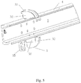
- Fig. 5 is a perspective view of the support assembly according to the present disclosure mounted on the bracket.
- the support assembly 3 comprises a supporting plate 35, a first supporting block 31 and a second supporting block 32, with the supporting plate 35 fixed on the bracket 4, and the first supporting block 31 and the second supporting block 32 fixed on the supporting plate 35.
- the first supporting block 31 and the second supporting block 32 are on the inner sides of the drive chain 11, and then supporting forces are applied in opposite directions to the drive chain 11 to move portions of the drive chain between the driving wheel 13 and the driven wheel 12 (shown in Fig.
- the first supporting block 31 and the second supporting block 32 can be fixed directly on the supporting plate 3.
- the first supporting block 31 and the second supporting block 32 can also be held through a first snap joint 33 and a second snap joint 34 fixed on the supporting plate 3, as shown in Figs. 4 and 5 .
- the first snap joint 33 and the second snap joint 34 each has a snapping groove, and each of the first supporting block 31 and the second supporting block 32 can be held by mating with one of the snapping groove.
- the first supporting block 31 and the second supporting block 32 also lie in the plane defined by the driving wheel 13, the driven wheel 12 and the drive chain 11.
- surfaces of the first block 21 and the second block 22, which contact with the drive chain 11, are smooth surfaces, with a cross section of shape of a quarter of an ellipse taken along the plane.
- the shape of the cross section can also be, for example, a quarter of an oblong, a quarter of an oval shape, a quarter of an ellipse, a quarter of an oblong and a quarter of an oval shape etc.
- a function of the support assembly 3 is to be used to cooperate with the tension device for the drive chain, so as to avoid the portions of the drive chain 11 between the driving wheel 13 and the driven wheel 12 to move inward so much by action of the tension device for the drive chain 2 that they contact with other components.
- Fig. 6 is a perspective view of a tension device for a drive chain according to another embodiment of the present disclosure. This embodiment is similar to those shown in Figs. 1-3 , and same components are referenced by same reference numbers as those in Figs. 1-3 . Differences lie in that the weight and the cable wire are replaced by a pre-loaded spring 5'provided on a spring support rod 6' with a spring adjuster 7.
- a spring support rod fastener 26' is provided on one connecting rod 24.
- One end of the spring support rod 6' is secured to the one connecting rod 24.
- a spring support rod guiding and supporting member 27' is provided on the other connecting rod 25. The other end of the spring support rod extends through the spring support rod guiding and supporting member 27'.
- the pre-loaded spring 5' and the spring adjuster 7 are supported on the spring support rod, with the spring adjuster 7 being disposed on an outer side of the connecting rods.
- the spring 5' is pre-pressed between the spring adjuster 7 and the spring support rod guiding and supporting member 27', so that the spring 5' applies pressures to the connecting rods 24, 25 through the spring support rod fastener 26' and the spring support rod guiding and supporting member 27', causing the connecting rods 24, 25 to rotate about respective hinges to be close to each other.
- pressing blocks 21 and 23 in turn apply pressures to the portions of drive chain between the driving wheel 13 and a driven wheel 12 so that the portions of the drive chain between the driving wheel and the driven wheel move to be close to each other to tension the drive chain automatically, if the drive chain loosens after running several months.
- the pre-loaded spring 5' and the spring adjuster 7 can be embodied to be disposed on inner sides of the connecting rods as well, which does not departure from the protection scope of the present disclosure.
- the spring 5' is pre-tensioned between the spring adjuster 7 and the spring support rod guiding and supporting member 27', so that the spring 5' applies pulling forces to the connecting rods 24, 25 through the spring support rod fastener 26' and the spring support rod guiding and supporting member 27', causing the connecting rods 24, 25 to rotate about respective hinges to be close to each other.
- pressing blocks 21 and 23 apply pressures to the portions of the drive chain between the driving wheel 13 and a driven wheel 12 so that portions of the drive chain between the driving wheel 13 and the driven wheel 12 move to be close to each other to tension the drive chain automatically, if the drive chain loosens after running several months.
Landscapes
- Engineering & Computer Science (AREA)
- General Engineering & Computer Science (AREA)
- Mechanical Engineering (AREA)
- Devices For Conveying Motion By Means Of Endless Flexible Members (AREA)
- Escalators And Moving Walkways (AREA)
Abstract
Description
- The present disclosure relates to a tension device for a drive chain of a handrail system of an escalator system, method and an escalator system using the same.
- An escalator system comprises a handrail system moving in correspondence with steps of the escalator. The handrail system comprises fixed balustrades and a handrail band with a moving path controlled by a handrail rail fixed on the balustrades. The handrail band is guided and tensioned by a drive device for the handrail band disposed in a lower bed of the escalator, which drives the handrail band to move in cycle without breaking away from the handrail rail.
- The drive device for the handrail band comprises a driving wheel, a driven wheel, a handrail band drive wheel connected with the driven wheel coaxially, and a handrail band drive chain connected between the drive wheel and the driven wheel in circle. The driving wheel is driven to rotate by a motor, and the handrail band drive wheel, connected with the driven wheel coaxially, is rotated by the handrail band drive chain connected between the driving wheel and the driven wheel in circle. The handrail band extends through a gap between the handrail band drive wheel and a guiding roll for the handrail, and is pressed against the handrail band drive wheel, so as to be driven to move in circle by a friction force between the handrail band and the handrail band drive wheel.
- A problem exists in the drive device for the handrail band of the prior art is, the handrail band drive chain will loosen after running several months, and a pivot point of the handrail band drive wheel needs to be moved far away from the driving wheel to a new pivot point position so as to tension the handrail band drive chain. Furthermore, a pivot point of the guiding roll for the handrail needs to be adjusted accordingly with the new pivot point position of the handrail band drive wheel, which brings a heavy work on site periodically, and hence a quality problem to the handrail system.
- Therefore there exists a need to improve a handrail system in the prior art, especially a handrail drive device, so as to eliminate or alleviate heavy work on site periodically for the handrail drive device, and improve quality of the handrail system.
- An object of the present disclosure is to provide a tension device for a drive chain, which can eliminate or alleviate heavy work on site periodically for the handrail drive device, and even can tension the drive chain of the escalator system automatically. Another object of the present is to provide an escalator system and a method using the tension device for the drive chain.
- According to one aspect of the present disclosure, a tension device for a drive chain is provided. The drive chain is mounted and rotated around a driving wheel and a driven wheel. The tension device comprises a pair of pressing blocks, each provided on one of outer sides of portions of the drive chain between the driving wheel and the driven wheel, respectively. The pressing blocks apply pressures to the drive chain portions so as to make them close to each other.
- Preferably, the pressures are applied by a weight connected with the pressing blocks.
- Preferably, the pressures are applied by a pre-loaded spring connected with the pressing blocks.
- Preferably, a cable wire fastener is provided on one connecting rod, a guiding and supporting member for the cable wire is provided on the other connecting rod, one end of the cable wire is fastened to the one connecting rod by the cable wire fastener, guided and supported by the guiding and supporting member on the other connecting rod, and the other end of the cable wire is connected to the weight. The weight applies pressures to the connecting rods through the cable wire fastener and the guiding and supporting member, at least one of the connecting rods rotate about the hinge to move the connecting rods close to each other, and the pressing blocks apply pressures to the drive chain, to move the portions of the drive chain close to each other.
- The cable wire fastener and the guiding and supporting member each is provided on the corresponding connecting rod at a position away from a connecting point of the corresponding connecting rod connected to the base plate.
- Preferably, a spring support rod fastener is provided on one connecting rod, by which a spring support rod is secured to the one connecting rod at one end. A guiding and supporting member for the spring support rod is provided on the other connecting rod, through which the other end of the spring support rod extends. A spring and a spring adjuster are supported on the guiding and supporting member, with the spring adjuster being disposed on outer side of the connecting rods and the spring being pre-pressed between the spring adjuster and the spring guiding and supporting member. The spring applies pressures to the connecting rods through the spring support rod fastener and the guiding and supporting member, to allow the connecting rods to rotate about respective hinges close to each other, and the pressing blocks to apply pressures to the drive chain to move the portions of the drive chain close to each other.
- Preferably, a spring support rod fastener is provided on one connecting rod, by which a spring support rod is secured to the one connecting rod at one end. A guiding and supporting member for the spring support rod is provided on the other connecting rod, through which the other end of the spring support rod extends. A spring and a spring adjuster are supported on the guiding and supporting member, with the spring adjuster being disposed between the connecting rods and the spring being pre-tensioned between the spring adjuster and the guiding and supporting member. The spring applies pulling forces to the connecting rods through the spring support rod fastener and the guiding and supporting member, to allow the connecting rods to rotate about respective hinges close to each other, and the pressing blocks to apply pressures to drive chain to move the drive chain portions close to each other.
- Preferably, a portion of the spring support rod located on the outer side of the connecting rods is provided with threads, and the spring adjuster is a nut cooperating with the threads.
- Preferably, each of the pressing blocks is connected to a base plate through a connecting rod, with at least one of the connecting rod connected to the base plate via a hinge, and the base plate is configured to secure the tension device with respect to the drive chain to allow the pressing block to act on outer sides of the portions of the drive chain between the driving wheel and the driven wheel.
- Preferably, the connecting rods and the pressing blocks lie in a plane parallel with that defined by the driving wheel, the driven wheel and the drive chain, and a contact surface of the pressing blocks contacting the drive chain is smooth.
- Preferably, the tension device further comprises a support assembly comprising a supporting plate and a pair of supporting blocks, with the supporting blocks secured to the supporting plate, and the supporting plate configured to secure the support assembly. The supporting blocks each lies on inner sides of the portions of the drive chain respectively to apply a supporting force to each of the portions when they are pressed inwardly beyond a supporting surface of the supporting blocks.
- Preferably, the supporting blocks lie in the plane defined by the drive wheel, the driven wheel and the drive chain, and the supporting surface of one of the supporting blocks is smooth.
- Preferably, the base plate comprises two pieces of plates connected and perpendicular to each other, one of which is provided with the hinge, and the other of which is configured to secure the tension device for the drive chain.
- According to one aspect of the present disclosure, an escalator is provided, which comprises the tension device mentioned above.
- According to one aspect of the present disclosure, a method is provided for tensioning a drive chain, comprising: providing the drive chain mounted and rotated around a drive wheel and a driven wheel, providing a pair of pressing blocks, each being on one of outer sides of portions of the drive chain between the driving wheel and the driven wheel, and applying a gravity of a weight or a pre-loaded force of a pre-loaded spring to the pressing blocks, to allow the pressing blocks apply pressures to the portions of the drive chain to move them close to each other.
- The present disclosure can eliminate loosening of the drive chain after running several months without a need to move a pivot point of the drive band drive wheel far away from that of the driving wheel to tension the drive chain for the handrail, and hence without a need to adjust handrail band guiding roll according to a new pivot point of the handrail band drive wheel, eliminate periodically heavy work on site for the escalator system and a drive system comprising the drive chain and improve quality thereof in a simple, reliable and low cost manner.
-
-
Fig. 1 is a perspective view of a handrail system comprising a tension device for a drive chain according to an embodiment of the present disclosure. -
Fig. 2 is a front perspective view of the tension device for the drive chain according to the embodiment of the present disclosure. -
Fig. 3 is a back perspective view of the tension device for the drive chain according to the embodiment of the present disclosure. -
Fig. 4 is a perspective view of the support assembly according to the present disclosure. -
Fig. 5 is a perspective view of the support assembly according to the present disclosure, which is mounted on a bracket. -
Fig. 6 is a perspective view of a tension device for a drive chain according to another embodiment of the present disclosure. - Various exemplary embodiments of the present disclosure will be described below with reference to the accompanying drawings. The present disclosure is not limited to the embodiments described. Directional terms mentioned in the description, such as: the inner side and the outer side, etc., are simply determined according to an orientation of a handrail system comprising a tension device for a drive chain, as shown in
Fig. 1 . -
Fig. 1 is a perspective view of a handrail system comprising a tension device for the drive chain according to the present disclosure. The handrail system is generally referenced byreference number 1. Thehandrail system 1 comprises adriving wheel 13 driven by a motor (not shown), a drivenwheel 12 rotating a handrail band drive wheel (not shown), and adrive chain 11 running in circle between thedriving wheel 13 and the drivenwheel 12. Generally, thedrive chain 11 will loosen and extend in length after running several months. Commonly, in the prior art, in view that the motor driving the handrail band drive wheel is commonly used with a driving device for driving steps of the escalator, a center of the drivenwheel 12 usually needs to be moved far away from that of thedriving wheel 13 of thehandrail system 1, so as to tension the looseneddrive chain 11. However, since the handrail band drive wheel is generally mounted coaxially with the drivenwheel 12, the center of the handrail band drive wheel needs to be moved far away from the center of thedriving wheel 13 correspondingly. As a result, to maintain normally running of the system, a position of a guiding roll mating with the handrail band drive wheel to guide the handrail needs to be adjusted correspondingly as well. Furthermore, such adjustments described above occur periodically, which brings a large amount work for maintenance and a problem on quality of the handrail system. - In
Fig. 1 , it is also shown a tension device for the drive chain according to the present disclosure referenced generally by areference number 2. InFig. 1 , the tension device for thedrive chain 2 is mounted to a bracket 4, which is a support truss of the escalator system. The tension device for thedrive chain 2 is subjected a force applied by a weight 5 via acable wire 6, and the tension device for thedrive chain 2 in turn applies the force to either outer side of portions of thedrive chain 11 between thedriving wheel 13 and the drivenwheel 12 to move the portions to be close to each other, so as to tension thedrive chain 11 automatically without need of periodic adjustment by a person. Optionally, the tension device for thedrive chain 2 can be made not to apply the force via thecable wire 6 with the weight 5, but to apply the force through a pulling bar, and the force needs to be adjusted periodically. Even in the case that the force needs to be adjusted periodically, comparing with the work for adjusting the center of the driven wheel far away from that of the driving wheel, the work for only periodically adjusting the force applied by the tension device for thedrive chain 2 to the drive chain is reduced obviously. - In
Fig. 1 , it is also shown a support assembly according to the present disclosure, which is generally referenced by areference number 3. Thesupport assembly 3 supports inner sides of thedrive chain 11 to apply support force to the drivenchain 11, so that in case it is used together with the tension device for thedrive chain 2, thesupport assembly 3 is used to prevent thedrive chain 11 from contacting any other components during tensioning of the drive chain. - The
support assembly 3 shown inFig. 1 is fixed directly onto the bracket 4. In fact, if thesupport assembly 3 is fixed onto the bracket 4 via an assembly with a plurality of connecting rods, a same result of tensioning thedrive chain 11 can also be obtained, but differences lie in that thesupport assembly 3 fixed onto the bracket 4 via the assembly with a plurality of connecting rods apply forces in opposite directions to make portions of the drive chain between thedriving wheel 13 and the drivenwheel 12 to move far away from each other, so as to tension the drive chain. Again, the support forces can be applied through corporation of the weight 5, thecable wire 6 and the assembly with a plurality of connecting rods fixed to the bracket, so as to tension thedrive chain 11 automatically without periodic adjustments by a person. Again, it is not necessary for thesupport assembly 3 to be fixed onto the bracket 4 via the assembly with a plurality of connecting rods to comprise the weight 5. The force is applied only through the assembly with a plurality of connecting rods, which can be adjusted periodically by a person. Thus, even in the case that the force needs to be adjusted periodically, comparing with the work for adjusting the center of the driven wheel far away from that of the driving wheel, the work for only periodically adjusting the force applied by the tension device for thedrive chain 2 to the drive chain is reduced obviously. -
Fig. 2 is a front perspective view of the tension device for thedrive chain 2 according to an embodiment of the present disclosure, andFig. 3 is a back perspective view of the tension device for thedrive chain 2 ofFig. 2 . FromFigs. 2 and3 , it can be seen that the tension device for thedrive chain 2 comprises abase plate 29, afirst hinge 27, asecond hinge 28, a first connectingrod 23, a second connectingrod 24, a firstpressing block 21, and a secondpressing block 22. Thebase plate 29 comprises afirst branch plate 291 and asecond branch plate 292 with an angle of about 90 degrees. Thesecond branch plate 292 is fixed to the bracket 4, and thefirst hinge 27 and thesecond hinge 28 are fixed to thefirst branch plate 291. One end of the first connectingrod 23 is connected with thefirst hinge 27, and the other end of the first connectingrod 23 is connected with and supports the firstpressing block 21. One end of the second connectingrod 24 is connected with thesecond hinge 28, and the other end of the second connectingrod 24 is connected with and supports the secondpressing block 22. Acable wire fastener 26 is secured to the second connectingrod 24 at a position far away from the second hinge 28e of the second connectingrod 24. A guiding and supporting member for thecable wire 25 is fixed to the first connectingrod 23 at a position far away from thefirst hinge 27 of the connectingrod 23. One end of thecable wire 6 inFig. 1 can be fixed to thecable wire fastener 26, and the other end of thecable wire 6 is guided and supported by the supporting and guiding member for thecable wire 25 and is connected with the weight 5. Thus the weight 5 can apply its gravity via the cable wire to thecable wire fastener 26 and the supporting and guiding member for thecable wire 25, and then apply forces to the first connectingrod 23 and the second connectingrod 24 to rotate the first connectingrod 23 and the second connectingrod 24 with respect to thefirst hinge 27 and thesecond hinge 28 respectively to be close to each other. The forces are applied via the firstpressing block 21 and the secondpressing block 22 on outer sides of the portions of thedrive chain 11 between thedriving wheel 13 and the drivenwheel 12, to move the portions to be close to each other so as to tension thedrive chain 11. In this embodiment, the tension device for thedrive chain 2 is subjected to the forces applied by the weight 5 via thecable wire 6, and it in turn applies the forces to the outer sides of the portions of thedrive chain 11 between thedriving wheel 13 and the drivenwheel 12 to move the portions to be close to each other, so as to tension thedrive chain 11 automatically without periodic adjustments by a person. - In an embodiment according to the present disclosure, a first connecting
rod 23 and a second connectingrod 24 do not apply forces through the cable wire with a weight, but apply forces only through a pulling bar at a position of the first connectingrod 23 and the second connectingrod 24 far away from afirst hinge 27 and asecond hinge 28 to rotate the first connectingrod 23 and the second connectingrod 24 with respect to thefirst hinge 27 and thesecond hinge 28 respectively to move closely to each other. Then the first connectingrod 23 and the second connectingrod 24 in turn apply forces to thedrive chain 11 at outer sides of the portions of thedrive chain 11 between thedriving wheel 13 and the drivenwheel 12 through a firstpressing block 21 and a secondpressing block 22 connected therewith respectively, so as to tension thehandrail drive chain 11. Comparing with the embodiments shown inFigs. 2 and3 , differences lie in that the forces applied by the pulling bar to the first connectingrod 23 and the second connectingrod 24 can be adjusted periodically by a person. As a result, although the embodiment, adjustments to the forces applied by the pulling bar are needed periodically by a person, comparing with the work for adjusting the center of the driven wheel far away from that of the driving wheel, the work for only periodically adjusting the force applied by the tension device for thedrive chain 2 to the drive chain is reduced obviously. - Turn back to
Fig. 1 . FromFig. 1 it can be seen that the first connectingrod 23, the second connectingrod 24, the firstpressing block 21 and the secondpressing block 22 lie in a plane in parallel with a plane defined by thedriving wheel 13, the drivenwheel 12 and thedrive chain 11. To reduce abrasion to thedrive chain 11 caused by the pressing blocks, surfaces of thefirst block 21 and thesecond block 22, which contact with thedrive chain 11, are smooth surfaces, with a cross section of shape of a half ellipse taken along the plane defined by thedriving wheel 13, the drivenwheel 12 and thedrive chain 11. The shape of the cross section can also be, for example, a half oblong, a half oval, an ellipse, an oblong and an oval etc. -
Fig. 4 is a perspective view of the support assembly according to the present disclosure andFig. 5 is a perspective view of the support assembly according to the present disclosure mounted on the bracket. FromFigs. 4 and5 it can be seen, thesupport assembly 3 comprises a supportingplate 35, a first supportingblock 31 and a second supportingblock 32, with the supportingplate 35 fixed on the bracket 4, and the first supportingblock 31 and the second supportingblock 32 fixed on the supportingplate 35. When the supportingplate 35 is fixed on the bracket 4, as shown inFig. 5 , the first supportingblock 31 and the second supportingblock 32 are on the inner sides of thedrive chain 11, and then supporting forces are applied in opposite directions to thedrive chain 11 to move portions of the drive chain between thedriving wheel 13 and the driven wheel 12 (shown inFig. 1 ) far away from each other. The first supportingblock 31 and the second supportingblock 32 can be fixed directly on the supportingplate 3. The first supportingblock 31 and the second supportingblock 32 can also be held through a first snap joint 33 and a second snap joint 34 fixed on the supportingplate 3, as shown inFigs. 4 and5 . The first snap joint 33 and the second snap joint 34 each has a snapping groove, and each of the first supportingblock 31 and the second supportingblock 32 can be held by mating with one of the snapping groove. The first supportingblock 31 and the second supportingblock 32 also lie in the plane defined by thedriving wheel 13, the drivenwheel 12 and thedrive chain 11. Again, to reduce abrasion to thedrive chain 11 when contacting with it, surfaces of thefirst block 21 and thesecond block 22, which contact with thedrive chain 11, are smooth surfaces, with a cross section of shape of a quarter of an ellipse taken along the plane. The shape of the cross section can also be, for example, a quarter of an oblong, a quarter of an oval shape, a quarter of an ellipse, a quarter of an oblong and a quarter of an oval shape etc. - A function of the
support assembly 3 is to be used to cooperate with the tension device for the drive chain, so as to avoid the portions of thedrive chain 11 between thedriving wheel 13 and the drivenwheel 12 to move inward so much by action of the tension device for thedrive chain 2 that they contact with other components. -
Fig. 6 is a perspective view of a tension device for a drive chain according to another embodiment of the present disclosure. This embodiment is similar to those shown inFigs. 1-3 , and same components are referenced by same reference numbers as those inFigs. 1-3 . Differences lie in that the weight and the cable wire are replaced by a pre-loaded spring 5'provided on a spring support rod 6' with a spring adjuster 7. - Specifically, in
Fig. 6 , a spring support rod fastener 26' is provided on one connectingrod 24. One end of the spring support rod 6' is secured to the one connectingrod 24. A spring support rod guiding and supporting member 27' is provided on the other connectingrod 25. The other end of the spring support rod extends through the spring support rod guiding and supporting member 27'. The pre-loaded spring 5' and the spring adjuster 7 are supported on the spring support rod, with the spring adjuster 7 being disposed on an outer side of the connecting rods. The spring 5' is pre-pressed between the spring adjuster 7 and the spring support rod guiding and supporting member 27', so that the spring 5' applies pressures to the connectingrods rods blocks driving wheel 13 and a drivenwheel 12 so that the portions of the drive chain between the driving wheel and the driven wheel move to be close to each other to tension the drive chain automatically, if the drive chain loosens after running several months. - The pre-loaded spring 5' and the spring adjuster 7 can be embodied to be disposed on inner sides of the connecting rods as well, which does not departure from the protection scope of the present disclosure. As a result, the spring 5' is pre-tensioned between the spring adjuster 7 and the spring support rod guiding and supporting member 27', so that the spring 5' applies pulling forces to the connecting
rods rods blocks driving wheel 13 and a drivenwheel 12 so that portions of the drive chain between thedriving wheel 13 and the drivenwheel 12 move to be close to each other to tension the drive chain automatically, if the drive chain loosens after running several months. - It should be noted that said embodiments are just illustrative, and should not be considered to limit the present disclosure. Some technical features in the embodiments may be combined to obtain more embodiments of the present disclosure, scope of which is only defined by attached claims. A plurality of variants and modifications can be made without departing from the scope of the present disclosure.
Claims (15)
- A tension device for a drive chain of an escalator, wherein the drive chain is mounted and rotated around a driving wheel and a driven wheel, comprising
a pair of pressing blocks, each provided on one of outer sides of portions of the drive chain between the driving wheel and the driven wheel, respectively,
wherein the pressing blocks apply pressures to the drive chain portions so as to make them close to each other. - The tension device of claim 1, wherein the pressures are applied by a weight connected with the pressing blocks.
- The tension device of claim 1, wherein the pressures are applied by a pre-loaded spring connected with the pressing blocks.
- The tension device of claim 1 or claim 2, wherein
a cable wire fastener is provided on one connecting rod,
a guiding and supporting member for the cable wire is provided on the other connecting rod,
one end of the cable wire is fastened to the one connecting rod by the cable wire fastener, guided and supported by the guiding and supporting member on the other connecting rod, and
the other end of the cable wire is connected to the weight, and
wherein the weight applies pressures to the connecting rods through the cable wire fastener and the guiding and supporting member, at least one of the connecting rods rotate about the hinge to move the connecting rods close to each other, and the pressing blocks apply pressures to the drive chain, to move the portions of the drive chain close to each other. - The tension device according to claim 4, wherein the cable wire fastener and the guiding and supporting member each is provided on the corresponding connecting rod at a position away from a connecting point of the corresponding connecting rod connected to the base plate.
- The tension device of claim 1 or claim 3, wherein
a spring support rod fastener is provided on one connecting rod, by which one end of a spring support rod is secured to the one connecting rod,
a guiding and supporting member for the spring support rod is provided on the other connecting rod, through which the other end of the spring support rod extends, and
a spring and a spring adjuster are supported on the guiding and supporting member, with the spring adjuster being disposed on outer side of the connecting rods and the spring being pre-pressed between the spring adjuster and the spring guiding and supporting member, and
wherein the spring applies pressures to the connecting rods through the spring support rod fastener and the guiding and supporting member, to allow the connecting rods to rotate about respective hinges close to each other, and the pressing blocks to apply pressures to the portions of the drive chain close to each other. - The tension device of claim 1 or claim 3, wherein
a spring support rod fastener is provided on one connecting rod, by which a spring support rod is secured to the one connecting rod at one end,
a guiding and supporting member for the spring support rod is provided on the other connecting rod, through which the other end of the spring support rod extends,
a spring and a spring adjuster are supported on the guiding and supporting member, with the spring adjuster being disposed between the connecting rods and the spring being pre-tensioned between the spring adjuster and the guiding and supporting member, and
the spring applies pulling forces to the connecting rods through the spring support rod fastener and the guiding and supporting member, to allow the connecting rods to rotate about respective hinges close to each other, and the pressing blocks to apply pressures to the drive chain to allow the drive chain portions close to each other. - The tension device of claim 6, wherein a portion of the spring support rod located on the outer side of the connecting rods is provided with threads, and the spring adjuster is a nut cooperating with the threads.
- The tension device of one of claims 1-8, wherein each of the pressing blocks is connected to a base plate through a connecting rod, with at least one of the connecting rod connected to the base plate via a hinge, and the base plate is configured to secure the tension device with respect to the drive chain to allow the pressing block to act on outer sides of the portions of the drive chain between the driving wheel and the driven wheel.
- The tension device according to one of claims 1-8, wherein the connecting rods and the pressing blocks lie in a plane parallel with that defined by the driving wheel, the driven wheel and the drive chain, and a contact surface of the pressing blocks contacting the drive chain is smooth.
- The tension device according to one of claims 1-8, further comprising,
a support assembly comprising a supporting plate and a pair of supporting blocks, with the supporting blocks secured to the supporting plate, and the supporting plate configured to secure the support assembly, and
wherein the supporting blocks each lies on inner sides of the portions of the drive chain respectively to apply a supporting force to each of the portions when they are pressed inwardly beyond a supporting surface of the supporting blocks. - The tension device according to claim 11, wherein the supporting blocks lie in the plane defined by the drive wheel, the driven wheel and the drive chain, and the supporting surface of one of the supporting blocks is smooth.
- The tension device according to claim 9, wherein the base plate comprises two pieces of plates connected and perpendicular to each other, one of which is provided with the hinge, and the other of which is configured to secure the tension device for the device chain.
- An escalator system, comprising the tension device of one of claims 1-13.
- A method for tensioning a drive chain of a handrail system of an escalator system, comprising:providing the drive chain mounted and rotated around a drive wheel and a driven wheel,providing a pair of pressing blocks, each being on one of outer sides of portions of the drive chain between the driving wheel and the driven wheel, andapplying a gravity of a weight or a pre-loaded force of a pre-loaded spring to the pressing blocks, to allow the pressing blocks apply pressures to the portions of the drive chain to move them close to each other.
Applications Claiming Priority (1)
| Application Number | Priority Date | Filing Date | Title |
|---|---|---|---|
| CN201710779739.0A CN107416659B (en) | 2017-09-01 | 2017-09-01 | Drive chain tensioning device and method and escalator system using same |
Publications (2)
| Publication Number | Publication Date |
|---|---|
| EP3461781A1 true EP3461781A1 (en) | 2019-04-03 |
| EP3461781B1 EP3461781B1 (en) | 2024-07-24 |
Family
ID=60435604
Family Applications (1)
| Application Number | Title | Priority Date | Filing Date |
|---|---|---|---|
| EP18192058.8A Active EP3461781B1 (en) | 2017-09-01 | 2018-08-31 | Tension device for drive chain, method and escalator system using same |
Country Status (3)
| Country | Link |
|---|---|
| US (1) | US10457524B2 (en) |
| EP (1) | EP3461781B1 (en) |
| CN (1) | CN107416659B (en) |
Families Citing this family (11)
| Publication number | Priority date | Publication date | Assignee | Title |
|---|---|---|---|---|
| CN110116959B (en) * | 2018-02-06 | 2024-09-13 | 通力电梯有限公司 | Handrail belt tensioning device for escalator |
| DE102018215451A1 (en) * | 2018-09-11 | 2020-03-12 | Bayerische Motoren Werke Aktiengesellschaft | Motorcycle with a tensioning device for tensioning a tension member and tensioning device for a motorcycle |
| EP3670419B1 (en) * | 2018-12-19 | 2023-01-25 | Otis Elevator Company | Method and device for monitoring chain tension |
| US12435774B2 (en) * | 2021-01-22 | 2025-10-07 | Borgwarner, Inc. | Tooth jump protection device |
| US12320425B2 (en) | 2021-01-22 | 2025-06-03 | Borgwarner Inc. | Tooth jump protection device |
| US11796040B2 (en) * | 2021-01-22 | 2023-10-24 | Borgwarner Inc. | Method(s) to apply tension to increase drivetrain jump torque capacity |
| DE102022100471B4 (en) * | 2022-01-11 | 2025-07-17 | Bayerische Motoren Werke Aktiengesellschaft | Belt drive for driving a motor vehicle, in particular a motorcycle, and motor vehicle, in particular a motorcycle |
| US12078245B2 (en) | 2022-05-31 | 2024-09-03 | Borgwarner Inc. | Face of tensioner guide or arm with pattern to influence chain system NVH performance |
| CN115557364A (en) * | 2022-09-16 | 2023-01-03 | 杭州西奥电梯有限公司 | Driving mechanism stabilizing system of moving sidewalk or escalator |
| CN118062705A (en) * | 2022-11-22 | 2024-05-24 | 奥的斯电梯公司 | Automatic conveying device |
| CN117718855A (en) * | 2024-02-02 | 2024-03-19 | 国网河南省电力公司焦作供电公司 | A cable grinding device |
Citations (6)
| Publication number | Priority date | Publication date | Assignee | Title |
|---|---|---|---|---|
| US2669339A (en) * | 1948-03-13 | 1954-02-16 | Westinghouse Electric Corp | Moving stairway |
| US3811332A (en) * | 1972-08-22 | 1974-05-21 | Fmc Corp | Automatic tensioning device |
| SU879105A1 (en) * | 1979-09-04 | 1981-11-07 | Головной Конструкторско-Технологический Институт По Комплектному Оборудованию Для Животноводства И Кормопроизводства | Tensioning apparatus for flexible-link transmissions |
| DE4427509A1 (en) * | 1994-08-03 | 1996-02-08 | Linde Ag | Traction drive able to run in both directions of rotation |
| CN2859091Y (en) * | 2005-11-17 | 2007-01-17 | 黄通明 | Chain fastening device |
| CN203781604U (en) * | 2014-01-24 | 2014-08-20 | 苏州富士电梯有限公司 | Lower-end handrail shaft mechanical driving device of escalator or moving sidewalk |
Family Cites Families (16)
| Publication number | Priority date | Publication date | Assignee | Title |
|---|---|---|---|---|
| US1304362A (en) * | 1919-05-20 | Confection-coating machine | ||
| CH517044A (en) * | 1971-02-24 | 1971-12-31 | Inventio Ag | Handrail drive for escalators and passenger conveyor belts |
| GB2232456B (en) * | 1989-06-08 | 1993-06-16 | Heidelberger Druckmasch Ag | Drive wheel phase relationship adjustment device |
| US5207308A (en) * | 1992-05-18 | 1993-05-04 | Otis Elevator Company | Moving handrail drive belt tensioning device |
| US6460679B1 (en) * | 2000-10-04 | 2002-10-08 | Otis Elevator Company | Automatically adjusting escalator handrail system |
| WO2006002679A1 (en) * | 2004-07-05 | 2006-01-12 | Otis Elevator Company | Handrail compensation device |
| US7632200B2 (en) * | 2005-06-06 | 2009-12-15 | Borgwarner Inc. | Common link dual arm tensioning device |
| ES2310465B1 (en) * | 2006-12-29 | 2009-11-10 | Thyssenkrupp Norte, S.A. | CARRIAGE FOR TRAILING HALLS OF CORRIDORS AND MOBILE STAIRS. |
| ES2340563B1 (en) * | 2008-01-18 | 2011-04-13 | Thyssenkrupp Elevator Innovation Center, S.A. | ROTARY SYSTEM OF LINEAR DRIVE OPERATION FOR MECHANICAL STAIRS AND ROLLING CORRIDORS. |
| BRPI0910393A8 (en) * | 2008-03-19 | 2019-01-29 | 2256355 Ontario Ltd | support for multi-connection protocols using transient logging and expanded bind revocation messages |
| JP2011522998A (en) | 2008-06-04 | 2011-08-04 | ボーグワーナー・インコーポレーテッド | Fixed mechanical strap tensioner for multi-strand tension adjustment |
| US8936147B2 (en) * | 2012-04-06 | 2015-01-20 | Dorner Mfg. Corp. | Pinch roller drive |
| CN202646563U (en) * | 2012-04-12 | 2013-01-02 | 中国嘉陵工业股份有限公司(集团) | Straining mechanism of chain transmission system or belt transmission system |
| DE102015211157A1 (en) * | 2015-06-17 | 2016-12-22 | Robert Bosch Gmbh | Method for determining torque in a belt drive |
| CN206145076U (en) * | 2016-11-10 | 2017-05-03 | 歌拉瑞电梯有限公司 | Drive chain's tight device that rises |
| CN207293898U (en) * | 2017-09-01 | 2018-05-01 | 通力股份公司 | Drive chain tension means and use its escalator system |
-
2017
- 2017-09-01 CN CN201710779739.0A patent/CN107416659B/en active Active
-
2018
- 2018-08-31 US US16/119,015 patent/US10457524B2/en active Active
- 2018-08-31 EP EP18192058.8A patent/EP3461781B1/en active Active
Patent Citations (6)
| Publication number | Priority date | Publication date | Assignee | Title |
|---|---|---|---|---|
| US2669339A (en) * | 1948-03-13 | 1954-02-16 | Westinghouse Electric Corp | Moving stairway |
| US3811332A (en) * | 1972-08-22 | 1974-05-21 | Fmc Corp | Automatic tensioning device |
| SU879105A1 (en) * | 1979-09-04 | 1981-11-07 | Головной Конструкторско-Технологический Институт По Комплектному Оборудованию Для Животноводства И Кормопроизводства | Tensioning apparatus for flexible-link transmissions |
| DE4427509A1 (en) * | 1994-08-03 | 1996-02-08 | Linde Ag | Traction drive able to run in both directions of rotation |
| CN2859091Y (en) * | 2005-11-17 | 2007-01-17 | 黄通明 | Chain fastening device |
| CN203781604U (en) * | 2014-01-24 | 2014-08-20 | 苏州富士电梯有限公司 | Lower-end handrail shaft mechanical driving device of escalator or moving sidewalk |
Also Published As
| Publication number | Publication date |
|---|---|
| CN107416659B (en) | 2020-10-02 |
| US20190071286A1 (en) | 2019-03-07 |
| US10457524B2 (en) | 2019-10-29 |
| EP3461781B1 (en) | 2024-07-24 |
| CN107416659A (en) | 2017-12-01 |
Similar Documents
| Publication | Publication Date | Title |
|---|---|---|
| EP3461781B1 (en) | Tension device for drive chain, method and escalator system using same | |
| US20140345431A1 (en) | Wire Saw | |
| KR101511013B1 (en) | Three roll type roll bending machine | |
| JP6176872B1 (en) | Man conveyor device | |
| AT517873B1 (en) | Ropeway carriage | |
| EP0861752B1 (en) | Installation machine for a catenery line | |
| KR100928422B1 (en) | Vibrators, Collectors, Conveyors | |
| WO2014090600A1 (en) | Double-decker lift with adjustable inter-car spacing | |
| DE4413422C1 (en) | Transportable drive arrangement | |
| AU2017344056B2 (en) | Mechanical actuation device with automatic compensation for secondary scrapers in conveyor belts | |
| KR102245785B1 (en) | Adhesive apparatus of tape for box package | |
| WO2014095429A1 (en) | Device for driving a handrail for an escalator or moving walkway | |
| CN204777229U (en) | Belt tightener | |
| DE2937293C2 (en) | Rope pressing device for rope sheaves | |
| DE3873671T2 (en) | SAFETY ROPING SYSTEMS, RELATED PARTS AND EQUIPMENT. | |
| CN204237463U (en) | Hand rail tension device and apply the handrail system of this device | |
| CN207293898U (en) | Drive chain tension means and use its escalator system | |
| KR20060006378A (en) | Cable traction | |
| DE2424435C2 (en) | Intermediate drive for a conveyor belt | |
| EP3521233B1 (en) | Escalator comprising handrail belt tension device | |
| JPWO2019012641A1 (en) | Emergency braking device for passenger conveyor | |
| JP2022070671A (en) | Follow-up type pulley unit and wire saw machine using the same | |
| DE102015001212A1 (en) | Load carrying friction wheel drive | |
| JP4606621B2 (en) | Rope gripping device | |
| JP6881851B2 (en) | Passenger conveyor |
Legal Events
| Date | Code | Title | Description |
|---|---|---|---|
| PUAI | Public reference made under article 153(3) epc to a published international application that has entered the european phase |
Free format text: ORIGINAL CODE: 0009012 |
|
| STAA | Information on the status of an ep patent application or granted ep patent |
Free format text: STATUS: THE APPLICATION HAS BEEN PUBLISHED |
|
| AK | Designated contracting states |
Kind code of ref document: A1 Designated state(s): AL AT BE BG CH CY CZ DE DK EE ES FI FR GB GR HR HU IE IS IT LI LT LU LV MC MK MT NL NO PL PT RO RS SE SI SK SM TR |
|
| AX | Request for extension of the european patent |
Extension state: BA ME |
|
| STAA | Information on the status of an ep patent application or granted ep patent |
Free format text: STATUS: REQUEST FOR EXAMINATION WAS MADE |
|
| 17P | Request for examination filed |
Effective date: 20191003 |
|
| RBV | Designated contracting states (corrected) |
Designated state(s): AL AT BE BG CH CY CZ DE DK EE ES FI FR GB GR HR HU IE IS IT LI LT LU LV MC MK MT NL NO PL PT RO RS SE SI SK SM TR |
|
| STAA | Information on the status of an ep patent application or granted ep patent |
Free format text: STATUS: EXAMINATION IS IN PROGRESS |
|
| 17Q | First examination report despatched |
Effective date: 20220131 |
|
| P01 | Opt-out of the competence of the unified patent court (upc) registered |
Effective date: 20230525 |
|
| GRAP | Despatch of communication of intention to grant a patent |
Free format text: ORIGINAL CODE: EPIDOSNIGR1 |
|
| STAA | Information on the status of an ep patent application or granted ep patent |
Free format text: STATUS: GRANT OF PATENT IS INTENDED |
|
| INTG | Intention to grant announced |
Effective date: 20240213 |
|
| GRAS | Grant fee paid |
Free format text: ORIGINAL CODE: EPIDOSNIGR3 |
|
| GRAA | (expected) grant |
Free format text: ORIGINAL CODE: 0009210 |
|
| STAA | Information on the status of an ep patent application or granted ep patent |
Free format text: STATUS: THE PATENT HAS BEEN GRANTED |
|
| AK | Designated contracting states |
Kind code of ref document: B1 Designated state(s): AL AT BE BG CH CY CZ DE DK EE ES FI FR GB GR HR HU IE IS IT LI LT LU LV MC MK MT NL NO PL PT RO RS SE SI SK SM TR |
|
| REG | Reference to a national code |
Ref country code: GB Ref legal event code: FG4D |
|
| REG | Reference to a national code |
Ref country code: CH Ref legal event code: EP |
|
| REG | Reference to a national code |
Ref country code: DE Ref legal event code: R096 Ref document number: 602018072102 Country of ref document: DE |
|
| REG | Reference to a national code |
Ref country code: IE Ref legal event code: FG4D |
|
| REG | Reference to a national code |
Ref country code: LT Ref legal event code: MG9D |
|
| REG | Reference to a national code |
Ref country code: NL Ref legal event code: MP Effective date: 20240724 |
|
| PG25 | Lapsed in a contracting state [announced via postgrant information from national office to epo] |
Ref country code: PT Free format text: LAPSE BECAUSE OF FAILURE TO SUBMIT A TRANSLATION OF THE DESCRIPTION OR TO PAY THE FEE WITHIN THE PRESCRIBED TIME-LIMIT Effective date: 20241125 |
|
| REG | Reference to a national code |
Ref country code: AT Ref legal event code: MK05 Ref document number: 1706156 Country of ref document: AT Kind code of ref document: T Effective date: 20240724 |
|
| PG25 | Lapsed in a contracting state [announced via postgrant information from national office to epo] |
Ref country code: NL Free format text: LAPSE BECAUSE OF FAILURE TO SUBMIT A TRANSLATION OF THE DESCRIPTION OR TO PAY THE FEE WITHIN THE PRESCRIBED TIME-LIMIT Effective date: 20240724 |
|
| PG25 | Lapsed in a contracting state [announced via postgrant information from national office to epo] |
Ref country code: PT Free format text: LAPSE BECAUSE OF FAILURE TO SUBMIT A TRANSLATION OF THE DESCRIPTION OR TO PAY THE FEE WITHIN THE PRESCRIBED TIME-LIMIT Effective date: 20241125 Ref country code: NL Free format text: LAPSE BECAUSE OF FAILURE TO SUBMIT A TRANSLATION OF THE DESCRIPTION OR TO PAY THE FEE WITHIN THE PRESCRIBED TIME-LIMIT Effective date: 20240724 |
|
| PG25 | Lapsed in a contracting state [announced via postgrant information from national office to epo] |
Ref country code: NO Free format text: LAPSE BECAUSE OF FAILURE TO SUBMIT A TRANSLATION OF THE DESCRIPTION OR TO PAY THE FEE WITHIN THE PRESCRIBED TIME-LIMIT Effective date: 20241024 |
|
| PG25 | Lapsed in a contracting state [announced via postgrant information from national office to epo] |
Ref country code: FI Free format text: LAPSE BECAUSE OF FAILURE TO SUBMIT A TRANSLATION OF THE DESCRIPTION OR TO PAY THE FEE WITHIN THE PRESCRIBED TIME-LIMIT Effective date: 20240724 Ref country code: GR Free format text: LAPSE BECAUSE OF FAILURE TO SUBMIT A TRANSLATION OF THE DESCRIPTION OR TO PAY THE FEE WITHIN THE PRESCRIBED TIME-LIMIT Effective date: 20241025 Ref country code: PL Free format text: LAPSE BECAUSE OF FAILURE TO SUBMIT A TRANSLATION OF THE DESCRIPTION OR TO PAY THE FEE WITHIN THE PRESCRIBED TIME-LIMIT Effective date: 20240724 |
|
| PG25 | Lapsed in a contracting state [announced via postgrant information from national office to epo] |
Ref country code: BG Free format text: LAPSE BECAUSE OF FAILURE TO SUBMIT A TRANSLATION OF THE DESCRIPTION OR TO PAY THE FEE WITHIN THE PRESCRIBED TIME-LIMIT Effective date: 20240724 |
|
| PG25 | Lapsed in a contracting state [announced via postgrant information from national office to epo] |
Ref country code: LV Free format text: LAPSE BECAUSE OF FAILURE TO SUBMIT A TRANSLATION OF THE DESCRIPTION OR TO PAY THE FEE WITHIN THE PRESCRIBED TIME-LIMIT Effective date: 20240724 |
|
| PG25 | Lapsed in a contracting state [announced via postgrant information from national office to epo] |
Ref country code: IS Free format text: LAPSE BECAUSE OF FAILURE TO SUBMIT A TRANSLATION OF THE DESCRIPTION OR TO PAY THE FEE WITHIN THE PRESCRIBED TIME-LIMIT Effective date: 20241124 Ref country code: AT Free format text: LAPSE BECAUSE OF FAILURE TO SUBMIT A TRANSLATION OF THE DESCRIPTION OR TO PAY THE FEE WITHIN THE PRESCRIBED TIME-LIMIT Effective date: 20240724 |
|
| PG25 | Lapsed in a contracting state [announced via postgrant information from national office to epo] |
Ref country code: HR Free format text: LAPSE BECAUSE OF FAILURE TO SUBMIT A TRANSLATION OF THE DESCRIPTION OR TO PAY THE FEE WITHIN THE PRESCRIBED TIME-LIMIT Effective date: 20240724 |
|
| PG25 | Lapsed in a contracting state [announced via postgrant information from national office to epo] |
Ref country code: ES Free format text: LAPSE BECAUSE OF FAILURE TO SUBMIT A TRANSLATION OF THE DESCRIPTION OR TO PAY THE FEE WITHIN THE PRESCRIBED TIME-LIMIT Effective date: 20240724 Ref country code: RS Free format text: LAPSE BECAUSE OF FAILURE TO SUBMIT A TRANSLATION OF THE DESCRIPTION OR TO PAY THE FEE WITHIN THE PRESCRIBED TIME-LIMIT Effective date: 20241024 |
|
| PG25 | Lapsed in a contracting state [announced via postgrant information from national office to epo] |
Ref country code: RS Free format text: LAPSE BECAUSE OF FAILURE TO SUBMIT A TRANSLATION OF THE DESCRIPTION OR TO PAY THE FEE WITHIN THE PRESCRIBED TIME-LIMIT Effective date: 20241024 Ref country code: PL Free format text: LAPSE BECAUSE OF FAILURE TO SUBMIT A TRANSLATION OF THE DESCRIPTION OR TO PAY THE FEE WITHIN THE PRESCRIBED TIME-LIMIT Effective date: 20240724 Ref country code: NO Free format text: LAPSE BECAUSE OF FAILURE TO SUBMIT A TRANSLATION OF THE DESCRIPTION OR TO PAY THE FEE WITHIN THE PRESCRIBED TIME-LIMIT Effective date: 20241024 Ref country code: LV Free format text: LAPSE BECAUSE OF FAILURE TO SUBMIT A TRANSLATION OF THE DESCRIPTION OR TO PAY THE FEE WITHIN THE PRESCRIBED TIME-LIMIT Effective date: 20240724 Ref country code: IS Free format text: LAPSE BECAUSE OF FAILURE TO SUBMIT A TRANSLATION OF THE DESCRIPTION OR TO PAY THE FEE WITHIN THE PRESCRIBED TIME-LIMIT Effective date: 20241124 Ref country code: HR Free format text: LAPSE BECAUSE OF FAILURE TO SUBMIT A TRANSLATION OF THE DESCRIPTION OR TO PAY THE FEE WITHIN THE PRESCRIBED TIME-LIMIT Effective date: 20240724 Ref country code: GR Free format text: LAPSE BECAUSE OF FAILURE TO SUBMIT A TRANSLATION OF THE DESCRIPTION OR TO PAY THE FEE WITHIN THE PRESCRIBED TIME-LIMIT Effective date: 20241025 Ref country code: FI Free format text: LAPSE BECAUSE OF FAILURE TO SUBMIT A TRANSLATION OF THE DESCRIPTION OR TO PAY THE FEE WITHIN THE PRESCRIBED TIME-LIMIT Effective date: 20240724 Ref country code: ES Free format text: LAPSE BECAUSE OF FAILURE TO SUBMIT A TRANSLATION OF THE DESCRIPTION OR TO PAY THE FEE WITHIN THE PRESCRIBED TIME-LIMIT Effective date: 20240724 Ref country code: BG Free format text: LAPSE BECAUSE OF FAILURE TO SUBMIT A TRANSLATION OF THE DESCRIPTION OR TO PAY THE FEE WITHIN THE PRESCRIBED TIME-LIMIT Effective date: 20240724 Ref country code: AT Free format text: LAPSE BECAUSE OF FAILURE TO SUBMIT A TRANSLATION OF THE DESCRIPTION OR TO PAY THE FEE WITHIN THE PRESCRIBED TIME-LIMIT Effective date: 20240724 |
|
| REG | Reference to a national code |
Ref country code: CH Ref legal event code: PL |
|
| PG25 | Lapsed in a contracting state [announced via postgrant information from national office to epo] |
Ref country code: SM Free format text: LAPSE BECAUSE OF FAILURE TO SUBMIT A TRANSLATION OF THE DESCRIPTION OR TO PAY THE FEE WITHIN THE PRESCRIBED TIME-LIMIT Effective date: 20240724 Ref country code: RO Free format text: LAPSE BECAUSE OF FAILURE TO SUBMIT A TRANSLATION OF THE DESCRIPTION OR TO PAY THE FEE WITHIN THE PRESCRIBED TIME-LIMIT Effective date: 20240724 Ref country code: DK Free format text: LAPSE BECAUSE OF FAILURE TO SUBMIT A TRANSLATION OF THE DESCRIPTION OR TO PAY THE FEE WITHIN THE PRESCRIBED TIME-LIMIT Effective date: 20240724 |
|
| PG25 | Lapsed in a contracting state [announced via postgrant information from national office to epo] |
Ref country code: LU Free format text: LAPSE BECAUSE OF NON-PAYMENT OF DUE FEES Effective date: 20240831 |
|
| PG25 | Lapsed in a contracting state [announced via postgrant information from national office to epo] |
Ref country code: CH Free format text: LAPSE BECAUSE OF NON-PAYMENT OF DUE FEES Effective date: 20240831 Ref country code: MC Free format text: LAPSE BECAUSE OF FAILURE TO SUBMIT A TRANSLATION OF THE DESCRIPTION OR TO PAY THE FEE WITHIN THE PRESCRIBED TIME-LIMIT Effective date: 20240724 Ref country code: EE Free format text: LAPSE BECAUSE OF FAILURE TO SUBMIT A TRANSLATION OF THE DESCRIPTION OR TO PAY THE FEE WITHIN THE PRESCRIBED TIME-LIMIT Effective date: 20240724 |
|
| PG25 | Lapsed in a contracting state [announced via postgrant information from national office to epo] |
Ref country code: CZ Free format text: LAPSE BECAUSE OF FAILURE TO SUBMIT A TRANSLATION OF THE DESCRIPTION OR TO PAY THE FEE WITHIN THE PRESCRIBED TIME-LIMIT Effective date: 20240724 |
|
| REG | Reference to a national code |
Ref country code: DE Ref legal event code: R097 Ref document number: 602018072102 Country of ref document: DE |
|
| PG25 | Lapsed in a contracting state [announced via postgrant information from national office to epo] |
Ref country code: SK Free format text: LAPSE BECAUSE OF FAILURE TO SUBMIT A TRANSLATION OF THE DESCRIPTION OR TO PAY THE FEE WITHIN THE PRESCRIBED TIME-LIMIT Effective date: 20240724 Ref country code: IT Free format text: LAPSE BECAUSE OF FAILURE TO SUBMIT A TRANSLATION OF THE DESCRIPTION OR TO PAY THE FEE WITHIN THE PRESCRIBED TIME-LIMIT Effective date: 20240724 |
|
| PLBE | No opposition filed within time limit |
Free format text: ORIGINAL CODE: 0009261 |
|
| STAA | Information on the status of an ep patent application or granted ep patent |
Free format text: STATUS: NO OPPOSITION FILED WITHIN TIME LIMIT |
|
| GBPC | Gb: european patent ceased through non-payment of renewal fee |
Effective date: 20241024 |
|
| REG | Reference to a national code |
Ref country code: BE Ref legal event code: MM Effective date: 20240831 |
|
| 26N | No opposition filed |
Effective date: 20250425 |
|
| PG25 | Lapsed in a contracting state [announced via postgrant information from national office to epo] |
Ref country code: GB Free format text: LAPSE BECAUSE OF NON-PAYMENT OF DUE FEES Effective date: 20241024 |
|
| PG25 | Lapsed in a contracting state [announced via postgrant information from national office to epo] |
Ref country code: BE Free format text: LAPSE BECAUSE OF NON-PAYMENT OF DUE FEES Effective date: 20240831 |
|
| PG25 | Lapsed in a contracting state [announced via postgrant information from national office to epo] |
Ref country code: FR Free format text: LAPSE BECAUSE OF NON-PAYMENT OF DUE FEES Effective date: 20240924 |
|
| PG25 | Lapsed in a contracting state [announced via postgrant information from national office to epo] |
Ref country code: IE Free format text: LAPSE BECAUSE OF NON-PAYMENT OF DUE FEES Effective date: 20240831 |
|
| PG25 | Lapsed in a contracting state [announced via postgrant information from national office to epo] |
Ref country code: SE Free format text: LAPSE BECAUSE OF FAILURE TO SUBMIT A TRANSLATION OF THE DESCRIPTION OR TO PAY THE FEE WITHIN THE PRESCRIBED TIME-LIMIT Effective date: 20240724 |
|
| PGFP | Annual fee paid to national office [announced via postgrant information from national office to epo] |
Ref country code: DE Payment date: 20250820 Year of fee payment: 8 |
|
| PG25 | Lapsed in a contracting state [announced via postgrant information from national office to epo] |
Ref country code: CY Free format text: LAPSE BECAUSE OF FAILURE TO SUBMIT A TRANSLATION OF THE DESCRIPTION OR TO PAY THE FEE WITHIN THE PRESCRIBED TIME-LIMIT; INVALID AB INITIO Effective date: 20180831 |
|
| PG25 | Lapsed in a contracting state [announced via postgrant information from national office to epo] |
Ref country code: HU Free format text: LAPSE BECAUSE OF FAILURE TO SUBMIT A TRANSLATION OF THE DESCRIPTION OR TO PAY THE FEE WITHIN THE PRESCRIBED TIME-LIMIT; INVALID AB INITIO Effective date: 20180831 |