EP3461740A1 - Position detection system for a slat flap lever control - Google Patents
Position detection system for a slat flap lever control Download PDFInfo
- Publication number
- EP3461740A1 EP3461740A1 EP18196944.5A EP18196944A EP3461740A1 EP 3461740 A1 EP3461740 A1 EP 3461740A1 EP 18196944 A EP18196944 A EP 18196944A EP 3461740 A1 EP3461740 A1 EP 3461740A1
- Authority
- EP
- European Patent Office
- Prior art keywords
- rfid
- rfid tags
- lever
- rfid reader
- tags
- Prior art date
- Legal status (The legal status is an assumption and is not a legal conclusion. Google has not performed a legal analysis and makes no representation as to the accuracy of the status listed.)
- Granted
Links
Images


Classifications
-
- G—PHYSICS
- G05—CONTROLLING; REGULATING
- G05B—CONTROL OR REGULATING SYSTEMS IN GENERAL; FUNCTIONAL ELEMENTS OF SUCH SYSTEMS; MONITORING OR TESTING ARRANGEMENTS FOR SUCH SYSTEMS OR ELEMENTS
- G05B19/00—Program-control systems
- G05B19/02—Program-control systems electric
- G05B19/04—Program control other than numerical control, i.e. in sequence controllers or logic controllers
- G05B19/12—Program control other than numerical control, i.e. in sequence controllers or logic controllers using record carriers
-
- B—PERFORMING OPERATIONS; TRANSPORTING
- B64—AIRCRAFT; AVIATION; COSMONAUTICS
- B64C—AEROPLANES; HELICOPTERS
- B64C13/00—Control systems or transmitting systems for actuating flying-control surfaces, lift-increasing flaps, air brakes, or spoilers
- B64C13/02—Initiating means
- B64C13/04—Initiating means actuated personally
- B64C13/042—Initiating means actuated personally operated by hand
- B64C13/0425—Initiating means actuated personally operated by hand for actuating trailing or leading edge flaps, air brakes or spoilers
-
- G—PHYSICS
- G06—COMPUTING OR CALCULATING; COUNTING
- G06K—GRAPHICAL DATA READING; PRESENTATION OF DATA; RECORD CARRIERS; HANDLING RECORD CARRIERS
- G06K7/00—Methods or arrangements for sensing record carriers, e.g. for reading patterns
- G06K7/10—Methods or arrangements for sensing record carriers, e.g. for reading patterns by electromagnetic radiation, e.g. optical sensing; by corpuscular radiation
- G06K7/10009—Methods or arrangements for sensing record carriers, e.g. for reading patterns by electromagnetic radiation, e.g. optical sensing; by corpuscular radiation sensing by radiation using wavelengths larger than 0.1 mm, e.g. radio-waves or microwaves
- G06K7/10297—Methods or arrangements for sensing record carriers, e.g. for reading patterns by electromagnetic radiation, e.g. optical sensing; by corpuscular radiation sensing by radiation using wavelengths larger than 0.1 mm, e.g. radio-waves or microwaves arrangements for handling protocols designed for non-contact record carriers such as RFIDs NFCs, e.g. ISO/IEC 14443 and 18092
-
- G—PHYSICS
- G05—CONTROLLING; REGULATING
- G05B—CONTROL OR REGULATING SYSTEMS IN GENERAL; FUNCTIONAL ELEMENTS OF SUCH SYSTEMS; MONITORING OR TESTING ARRANGEMENTS FOR SUCH SYSTEMS OR ELEMENTS
- G05B2219/00—Program-control systems
- G05B2219/20—Pc systems
- G05B2219/23—Pc programming
- G05B2219/23421—Record program on tape, disk, memory
-
- Y—GENERAL TAGGING OF NEW TECHNOLOGICAL DEVELOPMENTS; GENERAL TAGGING OF CROSS-SECTIONAL TECHNOLOGIES SPANNING OVER SEVERAL SECTIONS OF THE IPC; TECHNICAL SUBJECTS COVERED BY FORMER USPC CROSS-REFERENCE ART COLLECTIONS [XRACs] AND DIGESTS
- Y02—TECHNOLOGIES OR APPLICATIONS FOR MITIGATION OR ADAPTATION AGAINST CLIMATE CHANGE
- Y02T—CLIMATE CHANGE MITIGATION TECHNOLOGIES RELATED TO TRANSPORTATION
- Y02T50/00—Aeronautics or air transport
- Y02T50/40—Weight reduction
Definitions
- Exemplary embodiments pertain to the art of slat flap lever controls for aircrafts and, more particularly, to a position detection system and method associated with such slat flap lever controls.
- Aircraft slat and flap systems include slats and flaps that are extended and retracted at variable positions depending on the aircraft's take-off or landing situation to provide high lift to the aircraft at lower aircraft speeds. Actuation of the slats and flaps is provided in response to input from an aircraft operator. The input is made by movement of a slat flap control lever. Current levers are analog and implemented using a rotary variable differential transformer (RVDT). After many cycles, the reliability of the analog lever may deteriorate due to changes in the RVDT air gap and channel-to-channel variation.
- RVDT rotary variable differential transformer
- a system for positional monitoring of a slat flap lever control assembly including at least two radio frequency identification device (RFID) tags operatively coupled to a movable portion of the slat flap lever control assembly, the movable portion operatively coupled to a lever.
- RFID radio frequency identification device
- a RFID reader operatively coupled to a stationary portion of the slat flap lever control assembly and in operative communication with the at least two RFID tags.
- a controller comprising a processor operatively connected to the RFID reader. The processor is configured to transmit a carrier signal via the RFID reader to the at least two RFID tags.
- the processor is also configured to receive, via the RFID reader, at least two reflected signals from the at least two RFID tags, each of the at least two reflected signals comprising a different carrier frequency.
- the processor is further configured to determine, via the processor, based on the reflected signal from the at least two RFID tags, an angular position of the movable portion of the lever assembly relative to the stationary portion.
- further embodiments may include that the at least two RFID tags are in operative communication with a single channel of the RFID reader.
- further embodiments may include at least one additional channel of the RFID reader, each additional channel respectively in operative communication with a plurality of additional RFID tags.
- further embodiments may include that the numeral of total channels of the RFID reader corresponds to a total number of groups of RFID tags, the number of RFID tags in each of the total number of groups of RFID tags equaling a total number of discrete angular positions of the lever.
- further embodiments may include that the total number of discrete angular positions is five.
- further embodiments may include that the movable portion of the slat flap lever control assembly is a rotor operatively coupled to the lever.
- further embodiments may include a communication system in operative communication with the RFID reader.
- further embodiments may include that the communication system comprises a digital bus.
- the method includes transmitting, via a RFID reader, a carrier signal to at least two RFID tags.
- the method also includes receiving, via the RFID reader, at least two reflected signals from the at least two RFID tags, wherein each of the at least two reflected signals comprise a different carrier frequency.
- the method further includes determining, via a processor, based on the reflected signal from the at least two RFID tags, an angular position of a lever.
- further embodiments may include that the RFID reader comprises a plurality of channels, each of the channels in operative communication with respective groups of RFID tags to redundantly determine the angular position of the lever.
- each of the groups of RFID tags include five RFID tags.
- further embodiments may include communicating data received by the RFID reader to a digital bus.
- FIG. 1 illustrates a slat flap control lever assembly and is generally referenced with numeral 10.
- the lever assembly 10 includes a hand grip 12 for grasping by an operator and lever 14 that controls actuation of slats and flaps associated with an aircraft wing. Also provided is a finger lift 16 that allows movement of the lever 14 when lifted by the operator.
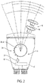
- FIG. 2 illustrates the lever assembly 10 in more detail.
- the lever 14 is movable over a range of five discrete angular positions.
- the lever 14 is rotatable over an angular range of positions, with discrete angular positions dictated by detents defined by a guide plate or the like. It is to be appreciated that five discrete angular positions is merely illustrative and that more or fewer discrete positions are contemplated. Verification that the lever 14 is in a desired angular position is provided with RFID technology via a RFID system 20, as described in detail herein.
- the RFID system 20 includes at least one RFID reader 22 configured on a stationary (unmovable) portion of the lever assembly 10.
- the RFID system 20 also includes a plurality of RFID tags 24 operatively coupled to one or more movable lever portions, such as the lever itself or a movable component 26 operatively coupled to the lever 14, such as a rotor. Movement of the movable component 26 corresponds to movement of the lever 14.
- RFID reader 22 is a multi-channel reader, with each channel outputting a predetermined carrier signal from the stationary portion of the lever 14 to one or more of the RFID tags 24.
- Each RFID tag 24 is configured to receive and reflect a carrier signal to the RFID reader 22.
- the RFID reader 22 is configured for signal output at multiple frequencies, where each of the output frequencies are different from each other. This may be facilitated by having a plurality of channels of the RFID reader 22, such as channels 28, 30, 32, 34 of the illustrated embodiment of FIG. 3 . It is contemplated that more or fewer channels are present in some embodiments.
- channel 28 is configured to interact with the column of RFID tags referenced with numeral 24a; channel 30 is configured to interact with the column of RFID tags referenced with numeral 24b; channel 32 is configured to interact with the column of RFID tags referenced with numeral 24c; and channel 34 is configured to interact with the column of RFID tags referenced with numeral 24d.
- the RFID reader 22 includes a signal generator, a signal transmitter, and a receiver, forming a RFID transceiver.
- the signal generator is configured to generate different carrier signals having different carrier frequencies.
- the signal transmitter includes one or more antenna configured to transmit the carrier signals generated by signal generator. Each of the signals generated have different carrier frequencies, such that when the signal is transmitted to an RFID tag 24, the reflected signal is received having the different frequency by one of the channels 28, 30, 32, 34.
- FIGS. 2 and 3 depict a movable lever portion 40 and a stationary lever portion 42 according to one embodiment.
- the movable lever portion 40 is a rotor that facilitates movement of the lever 14.
- the RFID reader 22 is attachable to the stationary lever portion 42 and configured to communicate with at least two RFID tags, each of the RFID tags corresponding to a different angular position of the lever 14. In the illustrated embodiment, five positions are shown and represented with five rows of RFID tags. In the example with four channels 28, 30, 32, 34, a total of 20 RFID tags 24 are present. Each of the channels 28, 30, 32, 34 are unique RFID receiver channels that receive a signal that indicates the position of the lever.
- the system can accurately measure distance (e.g., within ⁇ 1 mm of accuracy) and motion (a change in distance with respect to time) between each of RFID tags 24 at the different positions and the RFID reader 22 based on the amount of change in phase between the reflected signals received by the receiving section and the carrier signals and the frequencies of the carrier signals (i.e., triangulation).
- the distances can accurately determine a position for the lever 14.
- RFID reader 22 can receive at least two reflected signals from RFID tags 24 at different angular positions of the lever 14, where each of the at least two reflected signals have a different carrier frequency.
- five rows of RFID tags are shown on movable lever portion 40, it should be appreciated that there may be any number of RFID tags configured as an array on a single movable lever portion, and there may be multiple RFID readers configured to transmit a plurality of different carrier signals and receive their reflections from the multiple RFID tags on the panel.
- the RFID reader 22 is operatively connected to one or more communication system 50.
- the communication system 50 is a signal translator and data bus in some embodiments.
- the communication system 50 translates the signals to angular positions of the lever 14 and communicates the position to a controller or other device that alerts an operator of the position and/or corrects the angular position to a desired position.
- the RFID reader 22 communicates with four RFID tags of the plurality of RFID tags 24 to provide redundancy, and a controller.
- the controller includes a processor connected to the RFID reader 22.
- the processor transmits four channel carrier signals via the RFID reader 22 to the four RFID tags at an angular position (i.e., common row of FIG. 3 ). Each of the transmitted carrier signals have a unique carrier frequency.
- the processor also receives four reflected signals from RFID tags.
- the processor determines position based on the reflected signal from the four RFID tags.
- Each of the four RFID channels detects the lever's angle of rotation and the position of the lever 14.
- the data transmitted corresponds to the pilot's commanded slat and flap position on the wing.
- the data associated with the pilot's command is then used in the movement of the slats/flaps.
- the disclosed embodiments implement a four channel RFID between a positional rotary component and a four channel RFID transceiver.
- the rotational position from the RFID transceiver is translated to the communication system 50 (e.g., digital bus), such as CAN, ARINC 429, 1553, etc.
- the rotational positions are transmitted on the data bus as units of degrees and discrete in/out of detent position.
- the disclosed embodiments improve reliability due to the reduction in complexity of the system. This is attributed to contactless position sensors, precise sensing and a multi-channel redundant design. Additionally, the lever assembly weight is reduced by removing wire wound RVDT and reducing wiring harness weight by implementing a digital data bus.
- the embodiments disclosed herein can be a system, a method, and/or a computer program product at any possible technical detail level of integration
- the computer program product can include a computer readable storage medium (or media) having computer readable program instructions thereon for causing a processor to carry out aspects of the present disclosed embodiments.
- the computer readable storage medium can be a tangible device that can retain and store instructions for use by an instruction execution device.
- the computer readable storage medium can be, for example, but is not limited to, an electronic storage device, a magnetic storage device, an optical storage device, an electromagnetic storage device, a semiconductor storage device, or any suitable combination of the foregoing.
- a non-exhaustive list of more specific examples of the computer readable storage medium includes the following: a portable computer diskette, a hard disk, a random access memory (RAM), a read-only memory (ROM), an erasable programmable read-only memory (EPROM or Flash memory), a static random access memory (SRAM), a portable compact disc read-only memory (CD-ROM), a digital versatile disk (DVD), a memory stick, and any suitable combination of the foregoing.
- RAM random access memory
- ROM read-only memory
- EPROM or Flash memory erasable programmable read-only memory
- SRAM static random access memory
- CD-ROM compact disc read-only memory
- DVD digital versatile disk
- a memory stick any suitable combination of the foregoing.
- a computer readable storage medium is not to be construed as being transitory signals per se, such as radio waves or other freely propagating electromagnetic waves, electromagnetic waves propagating through a waveguide or other transmission media (e.g., light pulses passing through a fiber-optic cable), or electrical signals transmitted through a wire.
- Computer readable program instructions for carrying out operations of the disclosed embodiments can be assembler instructions, instruction-set-architecture (ISA) instructions, machine instructions, machine dependent instructions, microcode, firmware instructions, state-setting data, configuration data for integrated circuitry, or either source code or object code written in any combination of one or more programming languages, including an object oriented programming language such as Smalltalk, C++, or the like, and procedural programming languages, such as the "C" programming language or similar programming languages.
- the computer readable program instructions can execute entirely on the user's computer, partly on the user's computer, as a stand-alone software package, partly on the user's computer and partly on a remote computer or entirely on the remote computer or server.
- the remote computer can be connected to the user's computer through any type of network, including a local area network (LAN) or a wide area network (WAN), or the connection can be made to an external computer (for example, through the Internet using an Internet Service Provider).
- electronic circuitry including, for example, programmable logic circuitry, field-programmable gate arrays (FPGA), or programmable logic arrays (PLA) can execute the computer readable program instructions by utilizing state information of the computer readable program instructions to personalize the electronic circuitry, in order to perform aspects of the disclosed embodiments.
Landscapes
- Engineering & Computer Science (AREA)
- Physics & Mathematics (AREA)
- Automation & Control Theory (AREA)
- Health & Medical Sciences (AREA)
- General Physics & Mathematics (AREA)
- Toxicology (AREA)
- Aviation & Aerospace Engineering (AREA)
- Computer Networks & Wireless Communication (AREA)
- Computer Security & Cryptography (AREA)
- Electromagnetism (AREA)
- General Health & Medical Sciences (AREA)
- Artificial Intelligence (AREA)
- Computer Vision & Pattern Recognition (AREA)
- Theoretical Computer Science (AREA)
- Radar Systems Or Details Thereof (AREA)
Abstract
Description
- Exemplary embodiments pertain to the art of slat flap lever controls for aircrafts and, more particularly, to a position detection system and method associated with such slat flap lever controls.
- Aircraft slat and flap systems include slats and flaps that are extended and retracted at variable positions depending on the aircraft's take-off or landing situation to provide high lift to the aircraft at lower aircraft speeds. Actuation of the slats and flaps is provided in response to input from an aircraft operator. The input is made by movement of a slat flap control lever. Current levers are analog and implemented using a rotary variable differential transformer (RVDT). After many cycles, the reliability of the analog lever may deteriorate due to changes in the RVDT air gap and channel-to-channel variation.
- Disclosed herein is a system for positional monitoring of a slat flap lever control assembly including at least two radio frequency identification device (RFID) tags operatively coupled to a movable portion of the slat flap lever control assembly, the movable portion operatively coupled to a lever. Also included is a RFID reader operatively coupled to a stationary portion of the slat flap lever control assembly and in operative communication with the at least two RFID tags. Further included is a controller comprising a processor operatively connected to the RFID reader. The processor is configured to transmit a carrier signal via the RFID reader to the at least two RFID tags. The processor is also configured to receive, via the RFID reader, at least two reflected signals from the at least two RFID tags, each of the at least two reflected signals comprising a different carrier frequency. The processor is further configured to determine, via the processor, based on the reflected signal from the at least two RFID tags, an angular position of the movable portion of the lever assembly relative to the stationary portion.
- In addition to one or more of the features described above, or as an alternative, further embodiments may include that the at least two RFID tags are in operative communication with a single channel of the RFID reader.
- In addition to one or more of the features described above, or as an alternative, further embodiments may include at least one additional channel of the RFID reader, each additional channel respectively in operative communication with a plurality of additional RFID tags.
- In addition to one or more of the features described above, or as an alternative, further embodiments may include that the numeral of total channels of the RFID reader corresponds to a total number of groups of RFID tags, the number of RFID tags in each of the total number of groups of RFID tags equaling a total number of discrete angular positions of the lever.
- In addition to one or more of the features described above, or as an alternative, further embodiments may include that the total number of discrete angular positions is five.
- In addition to one or more of the features described above, or as an alternative, further embodiments may include that the movable portion of the slat flap lever control assembly is a rotor operatively coupled to the lever.
- In addition to one or more of the features described above, or as an alternative, further embodiments may include a communication system in operative communication with the RFID reader.
- In addition to one or more of the features described above, or as an alternative, further embodiments may include that the communication system comprises a digital bus.
- Also disclosed is a method of monitoring a lever position of a slat flap lever control. The method includes transmitting, via a RFID reader, a carrier signal to at least two RFID tags. The method also includes receiving, via the RFID reader, at least two reflected signals from the at least two RFID tags, wherein each of the at least two reflected signals comprise a different carrier frequency. The method further includes determining, via a processor, based on the reflected signal from the at least two RFID tags, an angular position of a lever.
- In addition to one or more of the features described above, or as an alternative, further embodiments may include that the RFID reader comprises a plurality of channels, each of the channels in operative communication with respective groups of RFID tags to redundantly determine the angular position of the lever.
- In addition to one or more of the features described above, or as an alternative, further embodiments may include that each of the groups of RFID tags include five RFID tags.
- In addition to one or more of the features described above, or as an alternative, further embodiments may include communicating data received by the RFID reader to a digital bus.
- The following descriptions should not be considered limiting in any way. With reference to the accompanying drawings, like elements are numbered alike:
-
FIG. 1 is a perspective view of a slat flap control lever assembly; -
FIG. 2 is a side, elevational schematic view of the slat flap control lever assembly; and -
FIG. 3 is a schematic view of a radio-frequency identification (RFID) system of the slat flap control lever assembly. - A detailed description of one or more embodiments of the disclosed apparatus and method are presented herein by way of exemplification and not limitation with reference to the Figures. The embodiments disclosed herein assist in the control of a slat flap control lever by precisely measuring its position and movement with respect to a stationary portion of a slat flap control lever assembly.
-
FIG. 1 illustrates a slat flap control lever assembly and is generally referenced withnumeral 10. Thelever assembly 10 includes ahand grip 12 for grasping by an operator and lever 14 that controls actuation of slats and flaps associated with an aircraft wing. Also provided is afinger lift 16 that allows movement of thelever 14 when lifted by the operator. -
FIG. 2 illustrates thelever assembly 10 in more detail. In the illustrated embodiment, thelever 14 is movable over a range of five discrete angular positions. Thelever 14 is rotatable over an angular range of positions, with discrete angular positions dictated by detents defined by a guide plate or the like. It is to be appreciated that five discrete angular positions is merely illustrative and that more or fewer discrete positions are contemplated. Verification that thelever 14 is in a desired angular position is provided with RFID technology via aRFID system 20, as described in detail herein. - Referring now to
FIGS 2 and3 , theRFID system 20 includes at least oneRFID reader 22 configured on a stationary (unmovable) portion of thelever assembly 10. TheRFID system 20 also includes a plurality ofRFID tags 24 operatively coupled to one or more movable lever portions, such as the lever itself or a movable component 26 operatively coupled to thelever 14, such as a rotor. Movement of the movable component 26 corresponds to movement of thelever 14. - In some aspects,
RFID reader 22 is a multi-channel reader, with each channel outputting a predetermined carrier signal from the stationary portion of thelever 14 to one or more of theRFID tags 24. EachRFID tag 24 is configured to receive and reflect a carrier signal to theRFID reader 22. TheRFID reader 22 is configured for signal output at multiple frequencies, where each of the output frequencies are different from each other. This may be facilitated by having a plurality of channels of theRFID reader 22, such aschannels FIG. 3 . It is contemplated that more or fewer channels are present in some embodiments. In the illustrated embodiment,channel 28 is configured to interact with the column of RFID tags referenced withnumeral 24a;channel 30 is configured to interact with the column of RFID tags referenced with numeral 24b;channel 32 is configured to interact with the column of RFID tags referenced withnumeral 24c; andchannel 34 is configured to interact with the column of RFID tags referenced withnumeral 24d. - The
RFID reader 22 includes a signal generator, a signal transmitter, and a receiver, forming a RFID transceiver. The signal generator is configured to generate different carrier signals having different carrier frequencies. The signal transmitter includes one or more antenna configured to transmit the carrier signals generated by signal generator. Each of the signals generated have different carrier frequencies, such that when the signal is transmitted to anRFID tag 24, the reflected signal is received having the different frequency by one of thechannels -
FIGS. 2 and3 depict amovable lever portion 40 and astationary lever portion 42 according to one embodiment. In some embodiments, themovable lever portion 40 is a rotor that facilitates movement of thelever 14. TheRFID reader 22 is attachable to thestationary lever portion 42 and configured to communicate with at least two RFID tags, each of the RFID tags corresponding to a different angular position of thelever 14. In the illustrated embodiment, five positions are shown and represented with five rows of RFID tags. In the example with fourchannels RFID tags 24 are present. Each of thechannels - Since the signals transmitted from
RFID reader 22 to the respective RFID tags are different from each other with respect to frequency, the system can accurately measure distance (e.g., within ±1 mm of accuracy) and motion (a change in distance with respect to time) between each ofRFID tags 24 at the different positions and theRFID reader 22 based on the amount of change in phase between the reflected signals received by the receiving section and the carrier signals and the frequencies of the carrier signals (i.e., triangulation). The distances can accurately determine a position for thelever 14. - Accordingly,
RFID reader 22 can receive at least two reflected signals fromRFID tags 24 at different angular positions of thelever 14, where each of the at least two reflected signals have a different carrier frequency. Although five rows of RFID tags are shown onmovable lever portion 40, it should be appreciated that there may be any number of RFID tags configured as an array on a single movable lever portion, and there may be multiple RFID readers configured to transmit a plurality of different carrier signals and receive their reflections from the multiple RFID tags on the panel. - The
RFID reader 22 is operatively connected to one ormore communication system 50. Thecommunication system 50 is a signal translator and data bus in some embodiments. Thecommunication system 50 translates the signals to angular positions of thelever 14 and communicates the position to a controller or other device that alerts an operator of the position and/or corrects the angular position to a desired position. - In some embodiments, the
RFID reader 22 communicates with four RFID tags of the plurality of RFID tags 24 to provide redundancy, and a controller. The controller includes a processor connected to theRFID reader 22. The processor transmits four channel carrier signals via theRFID reader 22 to the four RFID tags at an angular position (i.e., common row ofFIG. 3 ). Each of the transmitted carrier signals have a unique carrier frequency. The processor also receives four reflected signals from RFID tags. The processor determines position based on the reflected signal from the four RFID tags. Each of the four RFID channels detects the lever's angle of rotation and the position of thelever 14. The data transmitted corresponds to the pilot's commanded slat and flap position on the wing. The data associated with the pilot's command is then used in the movement of the slats/flaps. - The disclosed embodiments implement a four channel RFID between a positional rotary component and a four channel RFID transceiver. The rotational position from the RFID transceiver is translated to the communication system 50 (e.g., digital bus), such as CAN, ARINC 429, 1553, etc. The rotational positions are transmitted on the data bus as units of degrees and discrete in/out of detent position. The disclosed embodiments improve reliability due to the reduction in complexity of the system. This is attributed to contactless position sensors, precise sensing and a multi-channel redundant design. Additionally, the lever assembly weight is reduced by removing wire wound RVDT and reducing wiring harness weight by implementing a digital data bus.
- The term "about" is intended to include the degree of error associated with measurement of the particular quantity based upon the equipment available at the time of filing the application.
- The terminology used herein is for the purpose of describing particular embodiments only and is not intended to be limiting of the present disclosure. As used herein, the singular forms "a", "an" and "the" are intended to include the plural forms as well, unless the context clearly indicates otherwise. It will be further understood that the terms "comprises" and/or "comprising," when used in this specification, specify the presence of stated features, integers, steps, operations, elements, and/or components, but do not preclude the presence or addition of one or more other features, integers, steps, operations, element components, and/or groups thereof.
- The embodiments disclosed herein can be a system, a method, and/or a computer program product at any possible technical detail level of integration. The computer program product can include a computer readable storage medium (or media) having computer readable program instructions thereon for causing a processor to carry out aspects of the present disclosed embodiments.
- The computer readable storage medium can be a tangible device that can retain and store instructions for use by an instruction execution device. The computer readable storage medium can be, for example, but is not limited to, an electronic storage device, a magnetic storage device, an optical storage device, an electromagnetic storage device, a semiconductor storage device, or any suitable combination of the foregoing. A non-exhaustive list of more specific examples of the computer readable storage medium includes the following: a portable computer diskette, a hard disk, a random access memory (RAM), a read-only memory (ROM), an erasable programmable read-only memory (EPROM or Flash memory), a static random access memory (SRAM), a portable compact disc read-only memory (CD-ROM), a digital versatile disk (DVD), a memory stick, and any suitable combination of the foregoing. A computer readable storage medium, as used herein, is not to be construed as being transitory signals per se, such as radio waves or other freely propagating electromagnetic waves, electromagnetic waves propagating through a waveguide or other transmission media (e.g., light pulses passing through a fiber-optic cable), or electrical signals transmitted through a wire.
- Computer readable program instructions for carrying out operations of the disclosed embodiments can be assembler instructions, instruction-set-architecture (ISA) instructions, machine instructions, machine dependent instructions, microcode, firmware instructions, state-setting data, configuration data for integrated circuitry, or either source code or object code written in any combination of one or more programming languages, including an object oriented programming language such as Smalltalk, C++, or the like, and procedural programming languages, such as the "C" programming language or similar programming languages. The computer readable program instructions can execute entirely on the user's computer, partly on the user's computer, as a stand-alone software package, partly on the user's computer and partly on a remote computer or entirely on the remote computer or server. In the latter scenario, the remote computer can be connected to the user's computer through any type of network, including a local area network (LAN) or a wide area network (WAN), or the connection can be made to an external computer (for example, through the Internet using an Internet Service Provider). In some embodiments, electronic circuitry including, for example, programmable logic circuitry, field-programmable gate arrays (FPGA), or programmable logic arrays (PLA) can execute the computer readable program instructions by utilizing state information of the computer readable program instructions to personalize the electronic circuitry, in order to perform aspects of the disclosed embodiments.
- While the present disclosure has been described with reference to an exemplary embodiment or embodiments, it will be understood by those skilled in the art that various changes may be made and equivalents may be substituted for elements thereof without departing from the scope of the present disclosure. In addition, many modifications may be made to adapt a particular situation or material to the teachings of the present disclosure without departing from the scope of the invention as defined by the claims. Therefore, it is intended that the present disclosure not be limited to the particular embodiment disclosed as the best mode contemplated for carrying out this present disclosure, but that the present disclosure will include all embodiments falling within the scope of the claims.
Claims (12)
- A system for positional monitoring of a slat flap lever control assembly comprising:at least two radio frequency identification device, RFID, tags (24) operatively coupled to a movable portion (40) of the slat flap lever control assembly (10), the movable portion operatively coupled to a lever (14);a RFID (22) reader operatively coupled to a stationary portion (42) of the slat flap lever control assembly (10) and in operative communication with the at least two RFID tags (24); anda controller comprising a processor operatively connected to the RFID reader, the processor configured to:transmit a carrier signal via the RFID reader to the at least two RFID tags;receive, via the RFID reader, at least two reflected signals from the at least two RFID tags, each of the at least two reflected signals comprising a different carrier frequency; anddetermine, via the processor, based on the reflected signal from the at least two RFID tags, an angular position of the movable portion of the lever assembly relative to the stationary portion.
- The system of claim 1, wherein the at least two RFID tags are in operative communication with a single channel (28) of the RFID reader.
- The system of claim 2, further comprising at least one additional channel (28, 30, 32, 34) of the RFID reader, each additional channel respectively in operative communication with a plurality of additional RFID tags.
- The system of claim 3, wherein the numeral of total channels of the RFID reader corresponds to a total number of groups of RFID tags, the number of RFID tags in each of the total number of groups of RFID tags equaling a total number of discrete angular positions of the lever.
- The system of claim 4, wherein the total number of discrete angular positions is five.
- The system of any preceding claim, wherein the movable portion of the slat flap lever control assembly is a rotor operatively coupled to the lever.
- The system of any preceding claim, further comprising a communication system (50) in operative communication with the RFID reader.
- The system of claim 7, wherein the communication system comprises a digital bus.
- A method of monitoring a lever position of a slat flap lever control comprising:transmitting, via a RFID reader, a carrier signal to at least two RFID tags;receiving, via the RFID reader, at least two reflected signals from the at least two RFID tags, wherein each of the at least two reflected signals comprise a different carrier frequency; anddetermining, via a processor, based on the reflected signal from the at least two RFID tags, an angular position of a lever.
- The method of claim 9, wherein the RFID reader comprises a plurality of channels, each of the channels in operative communication with respective groups of RFID tags to redundantly determine the angular position of the lever.
- The method of claim 10, wherein each of the groups of RFID tags include five RFID tags.
- The method of claim 9, 10 or 11, further comprising communicating data received by the RFID reader to a digital bus.
Applications Claiming Priority (1)
| Application Number | Priority Date | Filing Date | Title |
|---|---|---|---|
| US15/718,212 US10216167B1 (en) | 2017-09-28 | 2017-09-28 | Position detection system for a slat flap lever control |
Publications (2)
| Publication Number | Publication Date |
|---|---|
| EP3461740A1 true EP3461740A1 (en) | 2019-04-03 |
| EP3461740B1 EP3461740B1 (en) | 2020-07-29 |
Family
ID=63914762
Family Applications (1)
| Application Number | Title | Priority Date | Filing Date |
|---|---|---|---|
| EP18196944.5A Active EP3461740B1 (en) | 2017-09-28 | 2018-09-26 | Position detection system for a slat flap lever control |
Country Status (2)
| Country | Link |
|---|---|
| US (1) | US10216167B1 (en) |
| EP (1) | EP3461740B1 (en) |
Cited By (1)
| Publication number | Priority date | Publication date | Assignee | Title |
|---|---|---|---|---|
| EP4371875A1 (en) * | 2022-11-21 | 2024-05-22 | Hamilton Sundstrand Corporation | Fiber optic slat flap system and control lever |
Families Citing this family (4)
| Publication number | Priority date | Publication date | Assignee | Title |
|---|---|---|---|---|
| US10824830B2 (en) * | 2018-06-05 | 2020-11-03 | Hamilton Sunstrand Corporation | RFID control surface disconnect detection system |
| CN111532418B (en) * | 2020-05-20 | 2021-09-24 | 中国商用飞机有限责任公司 | An aircraft high lift system |
| FR3122163B1 (en) * | 2021-04-21 | 2024-05-10 | Dassault Aviat | CONTROL SYSTEM FOR A HIGH LIFT ASSEMBLY OF AN AIRCRAFT |
| CN113772080A (en) * | 2021-09-30 | 2021-12-10 | 兰州万里航空机电有限责任公司 | A dual-margin flap control switch that can be operated with one hand |
Citations (3)
| Publication number | Priority date | Publication date | Assignee | Title |
|---|---|---|---|---|
| US4533096A (en) * | 1982-12-30 | 1985-08-06 | The Boeing Company | High lift system control assembly |
| US20140116194A1 (en) * | 2012-10-25 | 2014-05-01 | Cessna Aircraft Company | Self-centering aircraft flap position command apparatus |
| CN107187582A (en) * | 2017-07-31 | 2017-09-22 | 中国商用飞机有限责任公司 | Flap board operating handle |
Family Cites Families (8)
| Publication number | Priority date | Publication date | Assignee | Title |
|---|---|---|---|---|
| FR2917066B1 (en) | 2007-06-07 | 2010-05-21 | Messier Bugatti | METHOD FOR COLLECTING INFORMATION RELATING TO AERODYNAMIC AERODYNAMIC AIRCRAFT SURFACE |
| ITBO20120451A1 (en) * | 2012-08-23 | 2014-02-24 | Cefla Coop | CAMERA FOR MEDICAL USE WITH SELECTION OF DIFFERENT OPERATING MODES |
| US9555896B2 (en) | 2014-03-11 | 2017-01-31 | Textron Innovations Inc. | Aircraft flight control |
| US20170122779A1 (en) | 2014-03-28 | 2017-05-04 | Moog India Technology Centre Privated Limited | Angular position sensing device |
| WO2015160859A1 (en) * | 2014-04-14 | 2015-10-22 | Sirius Xm Radio Inc. | Systems, methods and applications for using and enhancing vehicle to vehicle communications including synergies and interoperation with satellite radio |
| US10871033B2 (en) * | 2014-12-23 | 2020-12-22 | Halliburton Energy Services, Inc. | Steering assembly position sensing using radio frequency identification |
| EP3394635B1 (en) * | 2015-12-21 | 2021-05-26 | Genetec Inc. | Vehicle positioning with rfid tags |
| US9970782B1 (en) * | 2016-03-24 | 2018-05-15 | The United States Of America As Represented By The Administrator Of The National Aeronautics And Space Administration | RFID-enabled angular position sensing system |
-
2017
- 2017-09-28 US US15/718,212 patent/US10216167B1/en active Active
-
2018
- 2018-09-26 EP EP18196944.5A patent/EP3461740B1/en active Active
Patent Citations (3)
| Publication number | Priority date | Publication date | Assignee | Title |
|---|---|---|---|---|
| US4533096A (en) * | 1982-12-30 | 1985-08-06 | The Boeing Company | High lift system control assembly |
| US20140116194A1 (en) * | 2012-10-25 | 2014-05-01 | Cessna Aircraft Company | Self-centering aircraft flap position command apparatus |
| CN107187582A (en) * | 2017-07-31 | 2017-09-22 | 中国商用飞机有限责任公司 | Flap board operating handle |
Cited By (2)
| Publication number | Priority date | Publication date | Assignee | Title |
|---|---|---|---|---|
| EP4371875A1 (en) * | 2022-11-21 | 2024-05-22 | Hamilton Sundstrand Corporation | Fiber optic slat flap system and control lever |
| US12351295B2 (en) | 2022-11-21 | 2025-07-08 | Hamilton Sundstrand Corporation | Fiber optic slat flap system and control lever |
Also Published As
| Publication number | Publication date |
|---|---|
| EP3461740B1 (en) | 2020-07-29 |
| US10216167B1 (en) | 2019-02-26 |
Similar Documents
| Publication | Publication Date | Title |
|---|---|---|
| EP3461740B1 (en) | Position detection system for a slat flap lever control | |
| US10293917B2 (en) | Methods and apparatus to control and monitor a folding wingtip actuation system | |
| US20200082731A1 (en) | System and Method for Detecting Obstacles in Aerial Systems | |
| EP2796956B1 (en) | Aircraft performance monitoring system | |
| EP2793096B1 (en) | Flight system for an aircraft having an autoland system | |
| EP3415417B1 (en) | Methods and apparatus for a distributed aircraft actuation system | |
| US8612070B2 (en) | Decision aid device for assisting the landing of an aircraft on the deck of a ship | |
| CN103979112A (en) | Method for predicting a trailing edge flap fault | |
| AU2017239611B2 (en) | Methods and apparatus to validate an aircraft control system command | |
| US20170021914A1 (en) | Fiber optic sensing and control system | |
| US10322816B2 (en) | Slat skew detection system and method | |
| EP3381795A1 (en) | Aircraft slat and flap control with radio frequency identification tags | |
| EP3505872B1 (en) | Method and system for detecting resolver/synchro faults | |
| EP3363741B1 (en) | System and method for validating rotorcraft position coordinates | |
| US11402858B2 (en) | Electronic stopper in actuator control | |
| KR102340694B1 (en) | The device for managing obstacle collision of drone | |
| US10407180B2 (en) | Interface system between a user and a display device in the cockpit of an aircraft, related aircraft and method | |
| CN103979113A (en) | Method for predicting a horizontal stabilizer fault | |
| EP2905224B1 (en) | Rotor state sensor system | |
| EP3602078B1 (en) | Method and system for determining an estimation of an anemometric parameter in an aircraft | |
| EP3756995A1 (en) | Methods and apparatus to measure multiple control surfaces with a sensor | |
| EP2955106B1 (en) | Rotorcraft flight parameter estimation | |
| EP4371875B1 (en) | Fiber optic slat flap system and control lever | |
| Lakshminarayan | Model-based fault detection for low-cost uav actuators | |
| Sun | Reliable air data solutions for small unmanned aircraft systems |
Legal Events
| Date | Code | Title | Description |
|---|---|---|---|
| PUAI | Public reference made under article 153(3) epc to a published international application that has entered the european phase |
Free format text: ORIGINAL CODE: 0009012 |
|
| STAA | Information on the status of an ep patent application or granted ep patent |
Free format text: STATUS: THE APPLICATION HAS BEEN PUBLISHED |
|
| AK | Designated contracting states |
Kind code of ref document: A1 Designated state(s): AL AT BE BG CH CY CZ DE DK EE ES FI FR GB GR HR HU IE IS IT LI LT LU LV MC MK MT NL NO PL PT RO RS SE SI SK SM TR |
|
| AX | Request for extension of the european patent |
Extension state: BA ME |
|
| STAA | Information on the status of an ep patent application or granted ep patent |
Free format text: STATUS: REQUEST FOR EXAMINATION WAS MADE |
|
| 17P | Request for examination filed |
Effective date: 20191004 |
|
| RBV | Designated contracting states (corrected) |
Designated state(s): AL AT BE BG CH CY CZ DE DK EE ES FI FR GB GR HR HU IE IS IT LI LT LU LV MC MK MT NL NO PL PT RO RS SE SI SK SM TR |
|
| GRAP | Despatch of communication of intention to grant a patent |
Free format text: ORIGINAL CODE: EPIDOSNIGR1 |
|
| STAA | Information on the status of an ep patent application or granted ep patent |
Free format text: STATUS: GRANT OF PATENT IS INTENDED |
|
| RIC1 | Information provided on ipc code assigned before grant |
Ipc: B64C 13/04 20060101AFI20191022BHEP |
|
| INTG | Intention to grant announced |
Effective date: 20191126 |
|
| GRAS | Grant fee paid |
Free format text: ORIGINAL CODE: EPIDOSNIGR3 |
|
| GRAA | (expected) grant |
Free format text: ORIGINAL CODE: 0009210 |
|
| STAA | Information on the status of an ep patent application or granted ep patent |
Free format text: STATUS: THE PATENT HAS BEEN GRANTED |
|
| AK | Designated contracting states |
Kind code of ref document: B1 Designated state(s): AL AT BE BG CH CY CZ DE DK EE ES FI FR GB GR HR HU IE IS IT LI LT LU LV MC MK MT NL NO PL PT RO RS SE SI SK SM TR |
|
| REG | Reference to a national code |
Ref country code: CH Ref legal event code: EP |
|
| REG | Reference to a national code |
Ref country code: AT Ref legal event code: REF Ref document number: 1295485 Country of ref document: AT Kind code of ref document: T Effective date: 20200815 |
|
| REG | Reference to a national code |
Ref country code: IE Ref legal event code: FG4D |
|
| REG | Reference to a national code |
Ref country code: DE Ref legal event code: R096 Ref document number: 602018006430 Country of ref document: DE |
|
| REG | Reference to a national code |
Ref country code: LT Ref legal event code: MG4D |
|
| REG | Reference to a national code |
Ref country code: NL Ref legal event code: MP Effective date: 20200729 |
|
| REG | Reference to a national code |
Ref country code: AT Ref legal event code: MK05 Ref document number: 1295485 Country of ref document: AT Kind code of ref document: T Effective date: 20200729 |
|
| PG25 | Lapsed in a contracting state [announced via postgrant information from national office to epo] |
Ref country code: PT Free format text: LAPSE BECAUSE OF FAILURE TO SUBMIT A TRANSLATION OF THE DESCRIPTION OR TO PAY THE FEE WITHIN THE PRESCRIBED TIME-LIMIT Effective date: 20201130 Ref country code: ES Free format text: LAPSE BECAUSE OF FAILURE TO SUBMIT A TRANSLATION OF THE DESCRIPTION OR TO PAY THE FEE WITHIN THE PRESCRIBED TIME-LIMIT Effective date: 20200729 Ref country code: BG Free format text: LAPSE BECAUSE OF FAILURE TO SUBMIT A TRANSLATION OF THE DESCRIPTION OR TO PAY THE FEE WITHIN THE PRESCRIBED TIME-LIMIT Effective date: 20201029 Ref country code: LT Free format text: LAPSE BECAUSE OF FAILURE TO SUBMIT A TRANSLATION OF THE DESCRIPTION OR TO PAY THE FEE WITHIN THE PRESCRIBED TIME-LIMIT Effective date: 20200729 Ref country code: GR Free format text: LAPSE BECAUSE OF FAILURE TO SUBMIT A TRANSLATION OF THE DESCRIPTION OR TO PAY THE FEE WITHIN THE PRESCRIBED TIME-LIMIT Effective date: 20201030 Ref country code: SE Free format text: LAPSE BECAUSE OF FAILURE TO SUBMIT A TRANSLATION OF THE DESCRIPTION OR TO PAY THE FEE WITHIN THE PRESCRIBED TIME-LIMIT Effective date: 20200729 Ref country code: HR Free format text: LAPSE BECAUSE OF FAILURE TO SUBMIT A TRANSLATION OF THE DESCRIPTION OR TO PAY THE FEE WITHIN THE PRESCRIBED TIME-LIMIT Effective date: 20200729 Ref country code: AT Free format text: LAPSE BECAUSE OF FAILURE TO SUBMIT A TRANSLATION OF THE DESCRIPTION OR TO PAY THE FEE WITHIN THE PRESCRIBED TIME-LIMIT Effective date: 20200729 Ref country code: FI Free format text: LAPSE BECAUSE OF FAILURE TO SUBMIT A TRANSLATION OF THE DESCRIPTION OR TO PAY THE FEE WITHIN THE PRESCRIBED TIME-LIMIT Effective date: 20200729 Ref country code: NO Free format text: LAPSE BECAUSE OF FAILURE TO SUBMIT A TRANSLATION OF THE DESCRIPTION OR TO PAY THE FEE WITHIN THE PRESCRIBED TIME-LIMIT Effective date: 20201029 |
|
| PG25 | Lapsed in a contracting state [announced via postgrant information from national office to epo] |
Ref country code: RS Free format text: LAPSE BECAUSE OF FAILURE TO SUBMIT A TRANSLATION OF THE DESCRIPTION OR TO PAY THE FEE WITHIN THE PRESCRIBED TIME-LIMIT Effective date: 20200729 Ref country code: LV Free format text: LAPSE BECAUSE OF FAILURE TO SUBMIT A TRANSLATION OF THE DESCRIPTION OR TO PAY THE FEE WITHIN THE PRESCRIBED TIME-LIMIT Effective date: 20200729 Ref country code: PL Free format text: LAPSE BECAUSE OF FAILURE TO SUBMIT A TRANSLATION OF THE DESCRIPTION OR TO PAY THE FEE WITHIN THE PRESCRIBED TIME-LIMIT Effective date: 20200729 Ref country code: IS Free format text: LAPSE BECAUSE OF FAILURE TO SUBMIT A TRANSLATION OF THE DESCRIPTION OR TO PAY THE FEE WITHIN THE PRESCRIBED TIME-LIMIT Effective date: 20201129 |
|
| PG25 | Lapsed in a contracting state [announced via postgrant information from national office to epo] |
Ref country code: NL Free format text: LAPSE BECAUSE OF FAILURE TO SUBMIT A TRANSLATION OF THE DESCRIPTION OR TO PAY THE FEE WITHIN THE PRESCRIBED TIME-LIMIT Effective date: 20200729 |
|
| PG25 | Lapsed in a contracting state [announced via postgrant information from national office to epo] |
Ref country code: EE Free format text: LAPSE BECAUSE OF FAILURE TO SUBMIT A TRANSLATION OF THE DESCRIPTION OR TO PAY THE FEE WITHIN THE PRESCRIBED TIME-LIMIT Effective date: 20200729 Ref country code: RO Free format text: LAPSE BECAUSE OF FAILURE TO SUBMIT A TRANSLATION OF THE DESCRIPTION OR TO PAY THE FEE WITHIN THE PRESCRIBED TIME-LIMIT Effective date: 20200729 Ref country code: CZ Free format text: LAPSE BECAUSE OF FAILURE TO SUBMIT A TRANSLATION OF THE DESCRIPTION OR TO PAY THE FEE WITHIN THE PRESCRIBED TIME-LIMIT Effective date: 20200729 Ref country code: DK Free format text: LAPSE BECAUSE OF FAILURE TO SUBMIT A TRANSLATION OF THE DESCRIPTION OR TO PAY THE FEE WITHIN THE PRESCRIBED TIME-LIMIT Effective date: 20200729 Ref country code: IT Free format text: LAPSE BECAUSE OF FAILURE TO SUBMIT A TRANSLATION OF THE DESCRIPTION OR TO PAY THE FEE WITHIN THE PRESCRIBED TIME-LIMIT Effective date: 20200729 Ref country code: SM Free format text: LAPSE BECAUSE OF FAILURE TO SUBMIT A TRANSLATION OF THE DESCRIPTION OR TO PAY THE FEE WITHIN THE PRESCRIBED TIME-LIMIT Effective date: 20200729 |
|
| REG | Reference to a national code |
Ref country code: DE Ref legal event code: R097 Ref document number: 602018006430 Country of ref document: DE |
|
| PG25 | Lapsed in a contracting state [announced via postgrant information from national office to epo] |
Ref country code: AL Free format text: LAPSE BECAUSE OF FAILURE TO SUBMIT A TRANSLATION OF THE DESCRIPTION OR TO PAY THE FEE WITHIN THE PRESCRIBED TIME-LIMIT Effective date: 20200729 |
|
| PLBE | No opposition filed within time limit |
Free format text: ORIGINAL CODE: 0009261 |
|
| STAA | Information on the status of an ep patent application or granted ep patent |
Free format text: STATUS: NO OPPOSITION FILED WITHIN TIME LIMIT |
|
| REG | Reference to a national code |
Ref country code: BE Ref legal event code: MM Effective date: 20200930 |
|
| PG25 | Lapsed in a contracting state [announced via postgrant information from national office to epo] |
Ref country code: LU Free format text: LAPSE BECAUSE OF NON-PAYMENT OF DUE FEES Effective date: 20200926 Ref country code: SK Free format text: LAPSE BECAUSE OF FAILURE TO SUBMIT A TRANSLATION OF THE DESCRIPTION OR TO PAY THE FEE WITHIN THE PRESCRIBED TIME-LIMIT Effective date: 20200729 |
|
| 26N | No opposition filed |
Effective date: 20210430 |
|
| PG25 | Lapsed in a contracting state [announced via postgrant information from national office to epo] |
Ref country code: BE Free format text: LAPSE BECAUSE OF NON-PAYMENT OF DUE FEES Effective date: 20200930 Ref country code: SI Free format text: LAPSE BECAUSE OF FAILURE TO SUBMIT A TRANSLATION OF THE DESCRIPTION OR TO PAY THE FEE WITHIN THE PRESCRIBED TIME-LIMIT Effective date: 20200729 Ref country code: IE Free format text: LAPSE BECAUSE OF NON-PAYMENT OF DUE FEES Effective date: 20200926 |
|
| REG | Reference to a national code |
Ref country code: CH Ref legal event code: PL |
|
| PG25 | Lapsed in a contracting state [announced via postgrant information from national office to epo] |
Ref country code: TR Free format text: LAPSE BECAUSE OF FAILURE TO SUBMIT A TRANSLATION OF THE DESCRIPTION OR TO PAY THE FEE WITHIN THE PRESCRIBED TIME-LIMIT Effective date: 20200729 Ref country code: MT Free format text: LAPSE BECAUSE OF FAILURE TO SUBMIT A TRANSLATION OF THE DESCRIPTION OR TO PAY THE FEE WITHIN THE PRESCRIBED TIME-LIMIT Effective date: 20200729 Ref country code: CY Free format text: LAPSE BECAUSE OF FAILURE TO SUBMIT A TRANSLATION OF THE DESCRIPTION OR TO PAY THE FEE WITHIN THE PRESCRIBED TIME-LIMIT Effective date: 20200729 |
|
| PG25 | Lapsed in a contracting state [announced via postgrant information from national office to epo] |
Ref country code: MK Free format text: LAPSE BECAUSE OF FAILURE TO SUBMIT A TRANSLATION OF THE DESCRIPTION OR TO PAY THE FEE WITHIN THE PRESCRIBED TIME-LIMIT Effective date: 20200729 Ref country code: MC Free format text: LAPSE BECAUSE OF FAILURE TO SUBMIT A TRANSLATION OF THE DESCRIPTION OR TO PAY THE FEE WITHIN THE PRESCRIBED TIME-LIMIT Effective date: 20200729 |
|
| PG25 | Lapsed in a contracting state [announced via postgrant information from national office to epo] |
Ref country code: LI Free format text: LAPSE BECAUSE OF NON-PAYMENT OF DUE FEES Effective date: 20210930 Ref country code: CH Free format text: LAPSE BECAUSE OF NON-PAYMENT OF DUE FEES Effective date: 20210930 |
|
| P01 | Opt-out of the competence of the unified patent court (upc) registered |
Effective date: 20230522 |
|
| PGFP | Annual fee paid to national office [announced via postgrant information from national office to epo] |
Ref country code: DE Payment date: 20250916 Year of fee payment: 8 |
|
| PGFP | Annual fee paid to national office [announced via postgrant information from national office to epo] |
Ref country code: GB Payment date: 20250919 Year of fee payment: 8 |
|
| PGFP | Annual fee paid to national office [announced via postgrant information from national office to epo] |
Ref country code: FR Payment date: 20250929 Year of fee payment: 8 |