EP3461720A1 - Vehicle control apparatus - Google Patents
Vehicle control apparatus Download PDFInfo
- Publication number
- EP3461720A1 EP3461720A1 EP18196798.5A EP18196798A EP3461720A1 EP 3461720 A1 EP3461720 A1 EP 3461720A1 EP 18196798 A EP18196798 A EP 18196798A EP 3461720 A1 EP3461720 A1 EP 3461720A1
- Authority
- EP
- European Patent Office
- Prior art keywords
- steering
- axial force
- calculation circuit
- control amount
- angle
- Prior art date
- Legal status (The legal status is an assumption and is not a legal conclusion. Google has not performed a legal analysis and makes no representation as to the accuracy of the status listed.)
- Granted
Links
Images





Classifications
-
- B—PERFORMING OPERATIONS; TRANSPORTING
- B62—LAND VEHICLES FOR TRAVELLING OTHERWISE THAN ON RAILS
- B62D—MOTOR VEHICLES; TRAILERS
- B62D6/00—Arrangements for automatically controlling steering depending on driving conditions sensed and responded to, e.g. control circuits
- B62D6/008—Control of feed-back to the steering input member, e.g. simulating road feel in steer-by-wire applications
-
- B—PERFORMING OPERATIONS; TRANSPORTING
- B62—LAND VEHICLES FOR TRAVELLING OTHERWISE THAN ON RAILS
- B62D—MOTOR VEHICLES; TRAILERS
- B62D5/00—Power-assisted or power-driven steering
- B62D5/04—Power-assisted or power-driven steering electrical, e.g. using an electric servo-motor connected to, or forming part of, the steering gear
- B62D5/0457—Power-assisted or power-driven steering electrical, e.g. using an electric servo-motor connected to, or forming part of, the steering gear characterised by control features of the drive means as such
- B62D5/046—Controlling the motor
- B62D5/0463—Controlling the motor calculating assisting torque from the motor based on driver input
-
- B—PERFORMING OPERATIONS; TRANSPORTING
- B62—LAND VEHICLES FOR TRAVELLING OTHERWISE THAN ON RAILS
- B62D—MOTOR VEHICLES; TRAILERS
- B62D5/00—Power-assisted or power-driven steering
- B62D5/04—Power-assisted or power-driven steering electrical, e.g. using an electric servo-motor connected to, or forming part of, the steering gear
- B62D5/0421—Electric motor acting on or near steering gear
-
- B—PERFORMING OPERATIONS; TRANSPORTING
- B62—LAND VEHICLES FOR TRAVELLING OTHERWISE THAN ON RAILS
- B62D—MOTOR VEHICLES; TRAILERS
- B62D6/00—Arrangements for automatically controlling steering depending on driving conditions sensed and responded to, e.g. control circuits
-
- B—PERFORMING OPERATIONS; TRANSPORTING
- B62—LAND VEHICLES FOR TRAVELLING OTHERWISE THAN ON RAILS
- B62D—MOTOR VEHICLES; TRAILERS
- B62D6/00—Arrangements for automatically controlling steering depending on driving conditions sensed and responded to, e.g. control circuits
- B62D6/002—Arrangements for automatically controlling steering depending on driving conditions sensed and responded to, e.g. control circuits computing target steering angles for front or rear wheels
Definitions
- the present invention relates to a vehicle control apparatus.
- This steering system includes a reaction motor and a steering operation motor.
- the reaction motor is a source of a steering reaction force to be applied to a steering shaft.
- the steering operation motor is a source of a steering operation force for turning the steered wheels.
- a control apparatus described in Japanese Patent Application Publication No. 2014-148299 calculates a feedforward axial force and a feedback axial force.
- the feedforward axial force is an ideal rack axial force based on a steering angle.
- the feedback axial force is an estimated axial force based on state variables of the vehicle (lateral acceleration, steering operation current, and yaw rate).
- the feedback axial force is calculated based on a blended axial force obtained by summing up, at predetermined blending ratios, axial forces calculated individually for the state variables of the vehicle.
- the control apparatus calculates a final axial force by summing up the feedforward axial force and the feedback axial force at predetermined blending ratios, and controls the reaction motor based on the final axial force.
- the feedback axial force reflects a road condition (road information), and therefore the steering reaction force generated by the reaction motor also reflects the road information. Thus, the driver can grasp the road information as the steering reaction force.
- the driver is informed of accurate road information through the steering wheel as tactile feedback, and can therefore perform a steering operation more quickly and more accurately. Further, a feeling of security in driving is enhanced. Therefore, a further improvement is desired for informing the driver of the road condition more appropriately as the steering reaction force (tactile feedback).
- a vehicle control apparatus is a vehicle control apparatus configured to control a motor based on a command value to be calculated based on a steering condition.
- the motor is a source of a driving force to be applied to a steering mechanism of a vehicle.
- the vehicle control apparatus includes a first calculation circuit, a second calculation circuit, and a third calculation circuit.
- the first calculation circuit is configured to calculate a first component of the command value based on at least a steering torque.
- the second calculation circuit is configured to calculate a target rotation angle of a rotating body based on a basic drive torque, which is a total sum of the steering torque and the first component.
- the rotating body is configured to rotate in association with a turning operation of a steered wheel.
- the third calculation circuit is configured to calculate a second component of the command value through feedback control performed so that an actual rotation angle of the rotating body equals the target rotation angle.
- the second calculation circuit includes an ideal axial force calculation circuit, an estimated axial force calculation circuit, a blending calculation circuit, and a subtractor.
- the ideal axial force calculation circuit is configured to calculate an ideal axial force based on the target rotation angle.
- the estimated axial force calculation circuit is configured to calculate, as an estimated axial force, an axial force applied to the steered wheel based on a state variable that reflects vehicle behavior or a road condition.
- the blending calculation circuit is configured to calculate a final axial force to be reflected in the basic drive torque as a reaction force component for the basic drive torque by summing up a value obtained by multiplying the ideal axial force by a blending ratio and a value obtained by multiplying the estimated axial force by a blending ratio.
- the blending ratios are set individually based on the state variable that reflects the vehicle behavior or the road condition or based on the steering condition.
- the subtractor is configured to calculate an axial force deviation, which is a difference between the ideal axial force and the estimated axial force.
- the first calculation circuit is configured to change the first component of the command value in response to the axial force deviation.
- the axial force deviation between the ideal axial force and the estimated axial force reflects the road condition.
- the axial force deviation is likely to occur between the ideal axial force and the estimated axial force.
- the axial force deviation has a larger value as a road grip decreases.
- the first component of the command value for the motor is changed in response to the axial force deviation, thereby calculating a command value that reflects the road condition more appropriately. Therefore, the motor generates a driving force that reflects the road condition more appropriately.
- the driver can acquire a more appropriate steering reaction force in response to the road condition as tactile feedback.
- the first calculation circuit may include a basic control amount calculation circuit, a compensation amount calculation circuit, and a calculator.
- the basic control amount calculation circuit is configured to calculate a basic control amount based on the steering condition.
- the basic control amount is a fundamental component of the first component of the command value.
- the compensation amount calculation circuit is configured to calculate a compensation amount for the fundamental component based on the steering condition.
- the calculator is configured to calculate the first component of the command value by summing up the fundamental component and the compensation amount.
- the first component of the command value may be changed by the basic control amount calculation circuit changing the basic control amount in response to the axial force deviation or the compensation amount calculation circuit changing the compensation amount in response to the axial force deviation.
- the compensation amount calculation circuit may include a stabilization control amount calculation circuit configured to calculate, based on the steering condition, a stabilization control amount for stabilizing a system.
- the first component of the command value may be changed by the stabilization control amount calculation circuit changing the stabilization control amount in response to the axial force deviation.
- the stabilization control amount is changed in response to the axial force deviation, thereby securing the system stability more appropriately based on the road condition.
- the compensation amount calculation circuit may include a hysteresis control amount calculation circuit configured to calculate, based on the steering condition, a hysteresis control amount for compensating a hysteresis characteristic caused by friction during a steering operation.
- the first component of the command value may be changed by the hysteresis control amount calculation circuit changing the hysteresis control amount in response to the axial force deviation.
- the hysteresis control amount is changed in response to the axial force deviation, thereby attaining a sense of friction based on the road condition.
- the compensation amount calculation circuit may include a steering wheel return control amount calculation circuit configured to calculate, based on the steering condition, a steering wheel return control amount for compensating a steering wheel return characteristic.
- the first component of the command value may be changed by the steering wheel return control amount calculation circuit changing the steering wheel return control amount in response to the axial force deviation.
- the steering wheel return control amount is changed in response to the axial force deviation, thereby attaining a steering wheel return characteristic based on the road condition.
- the compensation amount calculation circuit may include a damping control amount calculation circuit configured to calculate, based on the steering condition, a damping control amount for compensating a viscosity of the steering mechanism.
- the first component of the command value may be changed by the damping control amount calculation circuit changing the damping control amount in response to the axial force deviation.
- the damping control amount is changed in response to the axial force deviation, thereby attaining a sense of viscosity based on the road condition.
- the steering mechanism may include a steering operation shaft configured to turn the steered wheel by applying a steering operation force generated by a steering operation motor.
- the estimated axial force may be one of the following estimated axial forces:
- the estimated axial force to be used for calculating the axial force deviation is changed as appropriate.
- the steering mechanism may include a pinion shaft and a steering operation shaft.
- the pinion shaft serves as the rotating body and is mechanically separated from a steering wheel.
- the steering operation shaft is configured to turn the steered wheel in association with rotation of the pinion shaft.
- the steering mechanism may include a reaction motor and a steering operation motor as control targets of the vehicle control apparatus.
- the reaction motor serves as the motor and is configured to generate, based on the command value, a steering reaction force as the driving force to be applied to the steering wheel.
- the steering reaction force is a torque in a direction opposite to a steering direction.
- the steering operation motor is configured to generate a steering operation force for turning the steered wheel.
- the steering operation force is applied to the pinion shaft or the steering operation shaft.
- the steering mechanism may include a pinion shaft and a steering operation shaft.
- the pinion shaft serves as the rotating body and is configured to operate in association with a steering wheel.
- the steering operation shaft is configured to turn the steered wheel in association with rotation of the pinion shaft.
- the motor may be an assist motor configured to generate a steering assist force as the driving force to be applied to the steering wheel.
- the steering assist force is a torque in a direction identical to a steering direction.
- a steering system 10 for a vehicle includes a steering shaft 12 coupled to a steering wheel 11.
- a pinion shaft 13 is provided at the end of the steering shaft 12 that is located opposite to the steering wheel 11.
- Pinion teeth 13a of the pinion shaft 13 mesh with rack teeth 14a of a steering operation shaft 14 extending in a direction that intersects the pinion shaft 13.
- Right and left steered wheels 16 and 16 are coupled to both ends of the steering operation shaft 14 via tie rods 15 and 15, respectively.
- the steering shaft 12, the pinion shaft 13, and the steering operation shaft 14 function as a power transmission path between the steering wheel 11 and each of the steered wheels 16 and 16. That is, the steering operation shaft 14 performs linear motion along with a rotational operation of the steering wheel 11, thereby changing a steered angle ⁇ t of each of the steered wheels 16 and 16.
- the steering system 10 includes a clutch 21.
- the clutch 21 is provided on the steering shaft 12.
- An electromagnetic clutch is employed as the clutch 21.
- the electromagnetic clutch connects and disconnects power through connection and disconnection of electric power for an exciting coil.
- the clutch 21 is disengaged, the power transmission path between the steering wheel 11 and each of the steered wheels 16 and 16 is disconnected mechanically.
- the clutch 21 is engaged, the power transmission path between the steering wheel 11 and each of the steered wheels 16 and 16 is connected mechanically.
- the steering system 10 includes a reaction motor 31, a speed reducing mechanism 32, a rotation angle sensor 33, and a torque sensor 34 as a structure for generating a steering reaction force (reaction unit).
- the steering reaction force is a force (torque) to be applied in a direction opposite to a direction of a driver's operation of the steering wheel 11. By applying the steering reaction force to the steering wheel 11, the driver can acquire appropriate tactile feedback.
- the reaction motor 31 is a source of the steering reaction force.
- a three-phase (U, V, W) brushless motor is employed as the reaction motor 31.
- the reaction motor 31 (to be exact, its rotation shaft) is coupled to the steering shaft 12 via the speed reducing mechanism 32.
- the speed reducing mechanism 32 is provided at a part of the steering shaft 12 that is located on the steering wheel 11 side with respect to the clutch 21. A torque of the reaction motor 31 is applied to the steering shaft 12 as the steering reaction force.
- the rotation angle sensor 33 is provided on the reaction motor 31.
- the rotation angle sensor 33 detects a rotation angle ⁇ a of the reaction motor 31.
- the rotation angle ⁇ a of the reaction motor 31 is used for calculating a steering angle ⁇ s .
- the reaction motor 31 and the steering shaft 12 operate in association with each other via the speed reducing mechanism 32. Therefore, the rotation angle ⁇ a of the reaction motor 31 is correlated to the steering angle ⁇ s that is a rotation angle of the steering shaft 12 and furthermore a rotation angle of the steering wheel 11.
- the steering angle ⁇ s can be determined based on the rotation angle ⁇ a of the reaction motor 31.
- the torque sensor 34 detects a steering torque T h applied to the steering shaft 12 through a rotational operation of the steering wheel 11.
- the torque sensor 34 is provided at a part of the steering shaft 12 that is located on the steering wheel 11 side with respect to the speed reducing mechanism 32.
- the steering system 10 includes a steering operation motor 41, a speed reducing mechanism 42, and a rotation angle sensor 43 as a structure for generating a steering operation force (steering operation unit) that is power for turning the steered wheels 16 and 16.
- the steering operation motor 41 is a source of the steering operation force.
- a three-phase brushless motor is employed as the steering operation motor 41.
- the steering operation motor 41 (to be exact, its rotation shaft) is coupled to a pinion shaft 44 via the speed reducing mechanism 42. Pinion teeth 44a of the pinion shaft 44 mesh with rack teeth 14b of the steering operation shaft 14.
- a torque of the steering operation motor 41 is applied to the steering operation shaft 14 via the pinion shaft 44 as the steering operation force.
- the steering operation shaft 14 moves along a vehicle width direction (lateral direction in FIG. 1 ).
- the rotation angle sensor 43 is provided on the steering operation motor 41.
- the rotation angle sensor 43 detects a rotation angle ⁇ b of the steering operation motor 41.
- the steering system 10 includes a control apparatus 50.
- the control apparatus 50 controls the reaction motor 31, the steering operation motor 41, and the clutch 21 based on detection results from various sensors.
- a vehicle speed sensor 501 is provided in addition to the rotation angle sensor 33, the torque sensor 34, and the rotation angle sensor 43 described above.
- the vehicle speed sensor 501 is provided on the vehicle to detect a vehicle speed V that is a traveling speed of the vehicle.
- the control apparatus 50 executes engagement/disengagement control for switching engagement and disengagement of the clutch 21 based on whether a clutch engagement condition is satisfied.
- the clutch engagement condition include a condition that a power switch of the vehicle is OFF.
- the control apparatus 50 switches the clutch 21 from an engaged state to a disengaged state by energizing the exciting coil of the clutch 21.
- the control apparatus 50 switches the clutch 21 from the disengaged state to the engaged state by stopping the energization of the exciting coil of the clutch 21.
- the control apparatus 50 executes reaction control for generating a steering reaction force based on the steering torque T h through drive control for the reaction motor 31.
- the control apparatus 50 calculates a target steering reaction force based on at least the steering torque T h out of the steering torque T h and the vehicle speed V, and calculates a target steering angle of the steering wheel 11 based on the calculated target steering reaction force, the steering torque T h , and the vehicle speed V.
- the control apparatus 50 calculates a steering angle correction amount through feedback control of the steering angle ⁇ s , which is executed so that the actual steering angle ⁇ s follows the target steering angle, and calculates a steering reaction force command value by adding the calculated steering angle correction amount to the target steering reaction force.
- the control apparatus 50 supplies, to the reaction motor 31, a current necessary to generate a steering reaction force based on the steering reaction force command value.
- the control apparatus 50 executes steering operation control for turning the steered wheels 16 and 16 based on a steering condition through drive control for the steering operation motor 41.
- the control apparatus 50 calculates a pinion angle ⁇ p that is an actual rotation angle of the pinion shaft 44 based on the rotation angle ⁇ b of the steering operation motor 41 that is detected through the rotation angle sensor 43.
- the pinion angle ⁇ p is a value that reflects the steered angle ⁇ t of each of the steered wheels 16 and 16.
- the control apparatus 50 calculates a target pinion angle by using the target steering angle described above. Then, the control apparatus 50 determines a deviation between the target pinion angle and the actual pinion angle ⁇ p , and controls power supply to the steering operation motor 41 so as to eliminate the deviation.
- the control apparatus 50 includes a reaction control circuit 50a configured to execute the reaction control, and a steering operation control circuit 50b configured to execute the steering operation control.
- the reaction control circuit 50a includes a target steering reaction force calculation circuit 51, a target steering angle calculation circuit 52, a steering angle calculation circuit 53, a steering angle feedback control circuit 54, an adder 55, and an energization control circuit 56.
- the target steering reaction force calculation circuit 51 calculates a target steering reaction force T 1 * based on the steering torque T h .
- the target steering reaction force calculation circuit 51 may calculate the target steering reaction force T 1 * in consideration of the vehicle speed V.
- the target steering angle calculation circuit 52 calculates a target steering angle ⁇ * of the steering wheel 11 based on the target steering reaction force T 1 *, the steering torque T h , and the vehicle speed V.
- the target steering angle calculation circuit 52 has an ideal model that defines an ideal steering angle based on a basic drive torque (input torque), which is the total sum of the target steering reaction force T 1 * and the steering torque T h .
- the ideal model is obtained by modeling a steering angle corresponding to an ideal steered angle based on the basic drive torque through an experiment or the like in advance.
- the target steering angle calculation circuit 52 determines the basic drive torque by adding the target steering reaction force T 1 * and the steering torque T h together, and calculates the target steering angle ⁇ * from the basic drive torque based on the ideal model.
- the steering angle calculation circuit 53 calculates the actual steering angle ⁇ s of the steering wheel 11 based on the rotation angle ⁇ a of the reaction motor 31 that is detected through the rotation angle sensor 33.
- the steering angle feedback control circuit 54 calculates a steering angle correction amount T 2 * through feedback control of the steering angle ⁇ s so that the actual steering angle ⁇ s follows the target steering angle ⁇ *.
- the adder 55 calculates a steering reaction force command value T* by adding the steering angle correction amount T 2 * to the target steering reaction force T 1 *.
- the energization control circuit 56 supplies electric power to the reaction motor 31 based on the steering reaction force command value T*. Specifically, the energization control circuit 56 calculates a current command value for the reaction motor 31 based on the steering reaction force command value T*.
- the energization control circuit 56 detects an actual current value I a generated in a power supply path to the reaction motor 31 through a current sensor 57 provided in the power supply path.
- the current value I a is a value of an actual current supplied to the reaction motor 31.
- the energization control circuit 56 determines a deviation between the current command value and the actual current value I a , and controls power supply to the reaction motor 31 so as to eliminate the deviation (feedback control of the current value I a ).
- the reaction motor 31 generates a torque based on the steering reaction force command value T*.
- the driver can acquire appropriate tactile feedback in response to a road reaction force.
- the steering operation control circuit 50b includes a pinion angle calculation circuit 61, a steering angle ratio change control circuit 62, a differentiation steering control circuit 63, a pinion angle feedback control circuit 64, and an energization control circuit 65.
- the pinion angle calculation circuit 61 calculates the pinion angle ⁇ p that is an actual rotation angle of the pinion shaft 13 based on the rotation angle ⁇ b of the steering operation motor 41 that is detected through the rotation angle sensor 43.
- the steering operation motor 41 and the pinion shaft 13 operate in association with each other via the speed reducing mechanism 42. Therefore, there is a correlation between the rotation angle ⁇ b of the steering operation motor 41 and the pinion angle ⁇ p .
- the pinion angle ⁇ p can be determined from the rotation angle ⁇ b of the steering operation motor 41.
- the pinion shaft 13 meshes with the steering operation shaft 14.
- the pinion angle ⁇ p is a value that reflects the steered angle ⁇ t of each of the steered wheels 16 and 16.
- the steering angle ratio change control circuit 62 sets a steering angle ratio, which is the ratio of the steered angle ⁇ t to the steering angle ⁇ s , based on a traveling condition of the vehicle (for example, the vehicle speed V), and calculates a target pinion angle based on the set steering angle ratio.
- the steering angle ratio change control circuit 62 calculates a target pinion angle ⁇ p * so that the steered angle ⁇ t increases relative to the steering angle ⁇ s as the vehicle speed V decreases or that the steered angle ⁇ t decreases relative to the steering angle ⁇ s as the vehicle speed V increases.
- the steering angle ratio change control circuit 62 calculates a correction angle for the target steering angle ⁇ *, and adds the calculated correction angle to the target steering angle ⁇ *, thereby calculating the target pinion angle ⁇ p * based on the steering angle ratio.
- the differentiation steering control circuit 63 calculates a change speed of the target pinion angle ⁇ p * (steered speed) by differentiating the target pinion angle ⁇ p *.
- the differentiation steering control circuit 63 calculates a correction angle for the target pinion angle ⁇ p * by multiplying the change speed of the target pinion angle ⁇ p * by a gain.
- the differentiation steering control circuit 63 calculates a final target pinion angle ⁇ p * by adding the correction angle to the target pinion angle ⁇ p *.
- a delay in the steering operation is adjusted by advancing the phase of the target pinion angle ⁇ p * calculated by the steering angle ratio change control circuit 62. That is, a steering operation response is secured based on the steered speed.
- the pinion angle feedback control circuit 64 calculates a pinion angle command value T p * through feedback control (proportional-integral-derivative (PID) control) of the pinion angle ⁇ p so that the actual pinion angle ⁇ p follows the final target pinion angle ⁇ p * calculated by the differentiation steering control circuit 63.
- PID proportional-integral-derivative
- the energization control circuit 65 supplies electric power to the steering operation motor 41 based on the pinion angle command value T p *. Specifically, the energization control circuit 65 calculates a current command value for the steering operation motor 41 based on the pinion angle command value T p *. The energization control circuit 65 detects an actual current value I b generated in a power supply path to the steering operation motor 41 through a current sensor 66 provided in the power supply path. The current value I b is a value of an actual current supplied to the steering operation motor 41.
- the energization control circuit 65 determines a deviation between the current command value and the actual current value I b , and controls power supply to the steering operation motor 41 so as to eliminate the deviation (feedback control of the current value I b ).
- the steering operation motor 41 rotates by an angle based on the pinion angle command value T p *.
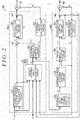
- the target steering reaction force calculation circuit 51 includes a basic control circuit 81, a system stabilization control circuit 82, a hysteresis control circuit 83, a steering wheel return control circuit 84, a damping control circuit 85, a calculator 86, and two differentiators 87 and 88.
- the differentiator 87 calculates a steering torque derivative dT h by differentiating the steering torque T h .
- the differentiator 88 calculates a steering speed ⁇ s by differentiating the steering angle ⁇ s .
- the basic control circuit 81 calculates a basic control amount I 1 * based on the steering torque T h and the vehicle speed V.
- the basic control amount I 1 * is a fundamental component (current value) for generating a target steering reaction force of an appropriate degree based on the steering torque T h and the vehicle speed V.
- the system stabilization control circuit 82 calculates a stabilization control amount I 2 * (current value) based on the steering torque derivative dT h and the vehicle speed V.
- the stabilization control amount I 2 * is a compensation amount for stabilizing the system by suppressing a resonance characteristic.
- An overall control system of the steering system 10 is stabilized by correcting the basic control amount I 1 * with the stabilization control amount I 2 *.
- the hysteresis control circuit 83 calculates a hysteresis control amount I 3 * that is a compensation amount for extending a tuning range of a target steering characteristic or a steering feel or for optimizing a hysteresis characteristic caused by friction during the steering operation.
- the hysteresis control circuit 83 calculates the hysteresis control amount I 3 * based on the steering angle ⁇ s and the vehicle speed V.
- the hysteresis control amount I 3 * has a hysteresis characteristic for a change in the steering angle ⁇ s .
- the steering wheel return control circuit 84 calculates a steering wheel return control amount I 4 * (current value) based on the steering torque T h , the vehicle speed V, the steering angle ⁇ s , and the steering speed ⁇ s .
- the steering wheel return control amount I 4 * is a compensation amount for compensating a return characteristic of the steering wheel 11.
- the damping control circuit 85 calculates a damping control amount I 5 * (current value) based on the steering speed ⁇ s and the vehicle speed V.
- the damping control amount I 5 * is a compensation amount for compensating the viscosity of the steering system 10. For example, small vibrations to be transmitted to the steering wheel 11 are reduced by correcting the basic control amount I 1 * with the damping control amount I 5 *.
- the calculator 86 calculates the target steering reaction force T 1 * (current value) by adding the stabilization control amount I 2 * and the steering wheel return control amount I 4 * to the basic control amount I 1 * and subtracting the hysteresis control amount I 3 * and the damping control amount I 5 * from the basic control amount I 1 * as correction processing for the basic control amount I 1 *.
- the target steering angle calculation circuit 52 calculates the target steering angle ⁇ * based on the ideal model from the basic drive torque, which is the total sum of the target steering reaction force T 1 * and the steering torque T h .
- the ideal model is a model using the fact that a basic drive torque T in * that is a torque applied to the steering shaft 12 is represented by Expression (1) below.
- T in * J ⁇ * ⁇ + C ⁇ * ⁇ + K ⁇ *
- the basic drive torque T in * is obtained by adding together a value obtained by multiplying a second-order time derivative ⁇ *" of the target steering angle ⁇ * by the moment of inertia J, a value obtained by multiplying a first-order time derivative ⁇ *' of the target steering angle ⁇ * by the coefficient of viscosity C, and a value obtained by multiplying the target steering angle ⁇ * by the spring modulus K.
- the target steering angle calculation circuit 52 calculates the target steering angle ⁇ * in accordance with the ideal model based on Expression (1).
- the ideal model based on Expression (1) is divided into a steering model 71 and a vehicle model 72.
- the steering model 71 is tuned based on characteristics of the components of the steering system 10, such as the steering shaft 12 and the reaction motor 31.
- the steering model 71 includes an adder 73, a subtractor 74, an inertia model 75, a first integrator 76, a second integrator 77, and a viscosity model 78.
- the adder 73 calculates the basic drive torque T in * by adding the target steering reaction force T 1 * and the steering torque T h together.
- the subtractor 74 calculates a final basic drive torque T in * by subtracting a viscosity component T vi * and a spring component T sp * described later from the basic drive torque T in * calculated by the adder 73.
- the inertia model 75 functions as an inertia control calculation circuit corresponding to the inertia term of Expression (1).
- the inertia model 75 calculates a steering angle acceleration ⁇ * by multiplying the final basic drive torque T in * calculated by the subtractor 74 and the inverse of the moment of inertia J together.
- the first integrator 76 calculates a steering angle speed ⁇ * by integrating the steering angle acceleration ⁇ * calculated by the inertia model 75.
- the second integrator 77 calculates the target steering angle ⁇ * by integrating the steering angle speed ⁇ * calculated by the first integrator 76.
- the target steering angle ⁇ * is an ideal rotation angle of the steering wheel 11 (steering shaft 12) based on the steering model 71.
- the viscosity model 78 functions as a viscosity control calculation circuit corresponding to the viscosity term of Expression (1).
- the viscosity model 78 calculates the viscosity component T vi * of the basic drive torque T in * by multiplying the steering angle speed ⁇ * calculated by the first integrator 76 and the coefficient of viscosity C together.
- the vehicle model 72 is tuned based on characteristics of the vehicle on which the steering system 10 is mounted.
- a vehicle-side characteristic that influences the steering characteristic is determined based on, for example, specifications of a suspension and wheel alignment and a grip force (friction force) of each of the steered wheels 16 and 16.
- the vehicle model 72 functions as a spring characteristic control calculation circuit corresponding to the spring term of Expression (1).
- the vehicle model 72 calculates the spring component T sp * (spring reaction torque) of the basic drive torque T in * by multiplying the target steering angle ⁇ * calculated by the second integrator 77 and the spring modulus K together.
- the vehicle model 72 calculates the spring component T sp *, the vehicle speed V and the current value I b of the steering operation motor 41 that is detected through the current sensor 66 are taken into consideration.
- the vehicle model 72 acquires a pinion angle speed ⁇ p .
- the pinion angle speed ⁇ p is obtained by the pinion angle ⁇ p calculated by the pinion angle calculation circuit 61 being differentiated by a differentiator 79 provided in the control apparatus 50.
- the pinion shaft 13 meshes with the steering operation shaft 14. Therefore, there is a correlation between a change speed of the pinion angle ⁇ p (pinion angle speed ⁇ p ) and a moving speed of the steering operation shaft 14 (steered speed).
- the pinion angle speed ⁇ p is a value that reflects the steered speed of each of the steered wheels 16 and 16.
- the steered speed may be determined from the pinion angle speed ⁇ p by using the correlation between the pinion angle speed ⁇ p and the steered speed.
- the relationship between the basic drive torque T in * and the target steering angle ⁇ * can be tuned directly and furthermore a desired steering characteristic can be achieved by adjusting the moment of inertia J and the coefficient of viscosity C of the steering model 71 and the spring modulus K of the vehicle model 72.
- the target pinion angle ⁇ p * is calculated by using the target steering angle ⁇ * calculated from the basic drive torque T in * based on the steering model 71 and the vehicle model 72. Then, feedback control is performed so that the actual pinion angle ⁇ p equals the target pinion angle ⁇ p *.
- the turning operation of each of the steered wheels 16 and 16 based on the basic drive torque T in * is also determined by the steering model 71 and the vehicle model 72. That is, the steering feel of the vehicle is determined by the steering model 71 and the vehicle model 72.
- a desired steering feel can be achieved by adjusting the steering model 71 and the vehicle model 72.
- the steering reaction force (tactile feedback to be acquired through a steering operation), which is a force (torque) to be applied in a direction opposite to the driver's steering direction, is only based on the target steering angle ⁇ *. That is, the steering reaction force does not change in response to a road condition (for example, the possibility of a slip that may occur on a road). Therefore, it is difficult for the driver to grasp the road condition through the steering reaction force.
- the vehicle model 72 has the following configuration from the viewpoint of addressing such concerns.
- the vehicle model 72 includes an imaginary rack end axial force calculation circuit 90, an ideal axial force calculation circuit 91, an estimated axial force calculation circuit 92, an estimated axial force calculation circuit 93, an estimated axial force calculation circuit 94, and an axial force blending calculation circuit 95.
- the imaginary rack end axial force calculation circuit 90 calculates an imaginary rack end axial force F end as a correction amount for the basic drive torque T in * in order to imaginarily limit the operation range of the steering wheel 11 to a range narrower than an original maximum physical steering range.
- the imaginary rack end axial force F end is calculated from the viewpoint of sharply increasing a torque (steering reaction torque) to be generated in the reaction motor 31 in a direction opposite to the steering direction.
- the limit position of the physical operation range of the steering wheel 11 is also a position at which the steering operation shaft 14 reaches the limit of its movable range.
- the steering operation shaft 14 reaches the limit of its movable range, there occurs a so-called “end abutment", in which the end of the steering operation shaft 14 (rack end) abuts against the housing. Therefore, the movement range of the rack shaft is physically limited.
- the operation range of the steering wheel is also limited.
- the imaginary rack end axial force calculation circuit 90 acquires the target steering angle ⁇ * and the target pinion angle ⁇ p * calculated by the steering angle ratio change control circuit 62 (see FIG. 2 ).
- the imaginary rack end axial force calculation circuit 90 calculates a target steered angle by multiplying the target pinion angle ⁇ p * by a predetermined conversion coefficient.
- the imaginary rack end axial force calculation circuit 90 compares the target steered angle with the target steering angle ⁇ *, and uses, as an imaginary rack end angle ⁇ end , one of the target steered angle and the target steering angle ⁇ * that is larger in the absolute value.
- the imaginary rack end axial force calculation circuit 90 calculates the imaginary rack end axial force F end by using an imaginary rack end map stored in a storage apparatus (not illustrated) of the control apparatus 50.
- the end determination threshold is set based on a value in the vicinity of the maximum physical steering range of the steering wheel 11 or a value in the vicinity of the maximum movable range of the steering operation shaft 14.
- the imaginary rack end axial force F end is a correction amount for the basic drive torque T in *, and is set to have the same sign as the sign (positive or negative) of the imaginary rack end angle ⁇ end .
- the imaginary rack end axial force F end is set to a larger value as the absolute value of the imaginary rack end angle ⁇ end increases.
- the ideal axial force calculation circuit 91 calculates an ideal axial force F i , which is an ideal value of the axial force to be applied to the steering operation shaft 14 through the steered wheels 16 and 16.
- the ideal axial force calculation circuit 91 calculates the ideal axial force F i by using an ideal axial force map stored in the storage apparatus (not illustrated) of the control apparatus 50.
- the ideal axial force F i is set to have a larger absolute value as the absolute value of the target steered angle obtained by multiplying the target pinion angle ⁇ p * by the predetermined conversion coefficient increases and as the vehicle speed V decreases.
- the ideal axial force F i may be calculated based on the target steered angle alone without considering the vehicle speed V.
- the estimated axial force calculation circuit 92 calculates an actual axial force F1 (road reaction force) to be applied to the steering operation shaft 14 (steered wheels 16 and 16) based on the current value I b of the steering operation motor 41.
- the current value I b of the steering operation motor 41 changes in response to the occurrence of a difference between the target pinion angle ⁇ p * and the actual pinion angle ⁇ p due to a situation in which a disturbance caused by a road condition (road frictional resistance) affects the steered wheels 16. That is, the current value I b of the steering operation motor 41 reflects an actual road reaction force applied to the steered wheels 16 and 16.
- an axial force that reflects an influence of the road condition can be calculated based on the current value I b of the steering operation motor 41.
- the axial force F1 is determined by multiplying the current value I b of the steering operation motor 41 by a gain that is a coefficient for converting a current value into an axial force (reaction torque).
- the estimated axial force calculation circuit 93 estimates and calculates an axial force F2 to be applied to the steering operation shaft 14 based on a lateral acceleration LA detected through a lateral acceleration sensor 502 provided in the vehicle.
- the axial force F2 is determined by multiplying the lateral acceleration LA by a gain that is a coefficient based on the vehicle speed V.
- the lateral acceleration LA reflects a road condition such as a road frictional resistance. Therefore, the axial force F2 calculated based on the lateral acceleration LA reflects an actual road condition.
- the estimated axial force calculation circuit 94 estimates and calculates an axial force F3 to be applied to the steering operation shaft 14 based on a yaw rate YR detected through a yaw rate sensor 503 provided in the vehicle.
- the axial force F3 is determined by multiplying together a yaw rate derivative that is a value obtained by differentiating the yaw rate YR and a vehicle speed gain that is a coefficient based on the vehicle speed V.
- the vehicle speed gain is set to a larger value as the vehicle speed V increases.
- the yaw rate YR reflects a road condition such as a road frictional resistance. Therefore, the axial force F3 calculated based on the yaw rate YR reflects an actual road condition.
- the axial force F3 may be calculated as follows. That is, the estimated axial force calculation circuit 94 determines the axial force F3 by adding at least one of a correction axial force based on the steered angle ⁇ t , a correction axial force based on the steered speed, and a correction axial force based on a steered angle acceleration to a value obtained by multiplying the yaw rate derivative by the vehicle speed gain.
- the steered angle ⁇ t is obtained by multiplying the pinion angle ⁇ p by a predetermined conversion coefficient.
- the steered speed may be obtained by differentiating the steered angle ⁇ t or by converting the pinion angle speed ⁇ p .
- the steered angle acceleration may be obtained by differentiating the steered speed or by converting a pinion angle acceleration ⁇ p .
- the axial force blending calculation circuit 95 calculates a final axial force F sp by summing up the imaginary rack end axial force F end , the ideal axial force F i , the axial force F1, the axial force F2, and the axial force F3 at predetermined blending ratios based on various state variables that reflect a traveling condition or a steering condition of the vehicle.
- the final axial force F sp is used for calculating the spring component T sp * for the basic drive torque T in *.
- the vehicle model 72 calculates (converts) the spring component T sp * for the basic drive torque T in * based on the axial force F sp .
- the axial force blending calculation circuit 95 includes a first calculation circuit 95a and a second calculation circuit 95b.
- the first calculation circuit 95a calculates a more appropriate estimated axial force F e by summing up, at predetermined blending ratios, the axial forces F1, F2, and F3 estimated and calculated by the estimated axial force calculation circuits 92, 93, and 94, respectively.
- the first calculation circuit 95a acquires the axial forces F1, F2, and F3, the yaw rate YR, and a lateral acceleration difference ⁇ LA.
- the lateral acceleration difference ⁇ LA is calculated by a difference calculation circuit 96 provided in the vehicle model 72.
- the difference calculation circuit 96 calculates the lateral acceleration difference ⁇ LA based on Expression (2) below.
- ⁇ LA YR ⁇ V ⁇ LA
- the first calculation circuit 95a includes an absolute value calculation circuit 97, blending ratio calculation circuits 98 and 99, multipliers 101, 103, and 105, adders 102 and 106, and a subtractor 104.
- the absolute value calculation circuit 97 calculates an absolute value
- the blending ratio calculation circuit 98 calculates a blending ratio D a based on the absolute value
- the blending ratio D a is set to a larger value as the absolute value
- the multiplier 101 calculates an axial force F a after blending by multiplying the axial force F3 based on the yaw rate YR and the blending ratio D a together.
- the adder 102 calculates an axial force F b by adding the axial force F2 based on the lateral acceleration LA and the axial force F a calculated by the multiplier 101 together.
- the blending ratio calculation circuit 99 calculates a blending ratio D b based on the yaw rate YR.
- the blending ratio D b is set to a larger value as the yaw rate YR increases and as the vehicle speed V increases.
- the multiplier 103 calculates an axial force F c by multiplying the axial force F b calculated by the adder 102 and the blending ratio D b together.
- the subtractor 104 calculates a blending ratio D c by subtracting the blending ratio D b calculated by the blending ratio calculation circuit 99 from "1", which is a fixed value stored in the storage apparatus of the control apparatus 50.
- the multiplier 105 calculates an axial force F d by multiplying the axial force F1 based on the current value I b of the steering operation motor 41 and the blending ratio D c together.
- the adder 106 calculates the final estimated axial force F e by adding the axial force F d calculated by the multiplier 105 and the axial force F e calculated by the multiplier 103 together.
- the second calculation circuit 95b calculates the final axial force F sp , which is used for calculating the spring component T sp * for the basic drive torque T in *, by summing up the estimated axial force F e calculated by the first calculation circuit 95a and the ideal axial force F i calculated by the ideal axial force calculation circuit 91 at predetermined blending ratios based on various state variables that reflect a traveling condition or a steering condition of the vehicle.
- the second calculation circuit 95b includes subtractors 107 and 117, blending ratio calculation circuits 108 to 114, multipliers 115, 116, and 118, and adders 119 and 120.
- the subtractor 107 calculates an axial force deviation ⁇ F by subtracting the estimated axial force F e calculated in a blended manner by the first calculation circuit 95a (adder 106) from the ideal axial force F i based on the target pinion angle ⁇ p *.
- the blending ratio calculation circuit 108 calculates a blending ratio Dcc based on the axial force deviation ⁇ F.
- the blending ratio Dcc is set to a larger value as the axial force deviation ⁇ F increases.
- the blending ratio calculation circuit 109 calculates a blending ratio D d based on the imaginary rack end angle ⁇ end .
- the blending ratio calculation circuit 110 calculates a blending ratio D e based on the pinion angle speed ⁇ p (may be converted into the steered speed).
- the blending ratio calculation circuit 111 calculates a blending ratio D f based on the steering speed ⁇ s obtained by differentiating the steering angle ⁇ s .
- the blending ratio calculation circuit 112 calculates a blending ratio D g based on the pinion angle ⁇ p .
- the blending ratio calculation circuit 113 calculates a blending ratio D h based on the steering angle ⁇ s .
- the blending ratio calculation circuit 114 calculates a blending ratio D i based on the vehicle speed V.
- the blending ratios D d , D e , D f , D g , D h , and D i are set to smaller values as the state variables ( ⁇ end , ⁇ p , ⁇ s , ⁇ p , ⁇ s , V) acquired by the respective blending ratio calculation circuits (109 to 114) increase.
- the multiplier 115 calculates a blending ratio D j of the final estimated axial force F e calculated by the first calculation circuit 95a by multiplying the blending ratios Dcc, D d , D e , D f , D g , D h , and D i together.
- the multiplier 116 calculates an estimated axial force F g after blending by multiplying the final estimated axial force F e calculated by the first calculation circuit 95a and the blending ratio D j based on the state variables together.
- the subtractor 117 calculates a blending ratio D k of the ideal axial force F i by subtracting the blending ratio D j calculated by the multiplier 115 from "1", which is a fixed value stored in the storage apparatus of the control apparatus 50.
- the multiplier 118 calculates an ideal axial force F h after blending by multiplying the ideal axial force F i calculated by the ideal axial force calculation circuit 91 and the blending ratio D k together.
- the adder 119 calculates an axial force F pre by summing up the ideal axial force F h after blending and the estimated axial force F g after blending.
- the adder 120 calculates the final axial force F sp , which is used for calculating the spring component T sp * for the basic drive torque T in *, by summing up the axial force F pre calculated by the adder 119 and the imaginary rack end axial force F end .
- the axial force F pre calculated by the adder 119 is used as the final axial force F sp , which is used for calculating the spring component T sp * for the basic drive torque T in *.
- the axial forces F1, F2, and F3 estimated and calculated based on the plurality of types of state variables that reflect vehicle behavior or a road condition and the ideal axial force F i calculated based on the target pinion angle ⁇ p * (target steered angle) are summed up at the blending ratios set based on the plurality of types of state variables that reflect the vehicle behavior, the steering condition, or the road condition.
- the axial force F pre (F sp ) that reflects the road condition more finely is calculated.
- the basic control circuit 81 has the following configuration.
- the basic control circuit 81 acquires the steering torque T h , the vehicle speed V, and the axial force deviation ⁇ F.
- the axial force deviation ⁇ F is a difference between the ideal axial force F i and the estimated axial force F e , which is calculated by the axial force blending calculation circuit 95 (see FIG. 6 ).
- the basic control circuit 81 includes two gain calculation circuits 121 and 122 and two multipliers 123 and 124.
- the gain calculation circuit 121 calculates a gain G1 by using a map that defines a relationship between the steering torque T h and the gain G1 depending on the vehicle speed V.
- the gain G1 is set to a larger value as the steering torque T h increases.
- the gain calculation circuit 122 calculates a gain G2 by using a map that defines a relationship between the axial force deviation ⁇ F and the gain G2.
- the gain G2 is set to a smaller value as the axial force deviation ⁇ F increases.
- the gain calculation circuit 122 may calculate the gain G2 in consideration of the steering torque T h .
- the multiplier 123 calculates a gain G3 by multiplying the gain Gland the gain G2 together.
- the multiplier 124 calculates the basic control amount I 1 * by multiplying the steering torque T h and the gain G3 together.
- the gain G3 reflects the gain G2 based on the axial force deviation ⁇ F. Therefore, the basic control amount I 1 * obtained by multiplying the steering torque T h and the gain G3 together and furthermore the target steering reaction force T 1 * based on the basic control amount I 1 * also reflect the axial force deviation ⁇ F.
- the axial force deviation ⁇ F is likely to occur between the ideal axial force F i and the estimated axial force F e .
- the reason is as follows. That is, the ideal axial force F i is calculated based on the target pinion angle ⁇ p *. Therefore, the ideal axial force F i is not likely to reflect the road condition.
- the estimated axial force F e is calculated based on various state variables. Therefore, the estimated axial force F e is likely to reflect the road condition.
- the ideal axial force F i only has a value based on the target pinion angle ⁇ p * irrespective of the tire grip condition, whereas the estimated axial force F e decreases as the road grip decreases. Accordingly, the difference between the ideal axial force F i and the estimated axial force F e increases as the road grip decreases. For this reason, the axial force deviation ⁇ F reflects the road condition.
- the basic control amount I 1 * is changed in response to the axial force deviation ⁇ F between the ideal axial force F i and the estimated axial force F e , thereby calculating a target steering reaction force T 1 * that reflects the road condition more appropriately.
- a more appropriate steering reaction force in response to the road grip is applied to the steering wheel 11.
- the driver feels the steering reaction force applied to the steering wheel 11 as tactile feedback, and can therefore grasp the road condition more accurately.
- the gain G2 is set to a smaller value as the axial force deviation ⁇ F increases along with a decrease in the road grip of the tire. Therefore, the basic control amount I 1 * and furthermore the target steering reaction force T 1 * have smaller values. That is, the steering reaction force to be applied to the steering shaft 12 decreases by an amount corresponding to the subtraction of the hysteresis control amount I 3 *. The steering torque T h necessary to operate the steering wheel 11 decreases by an amount corresponding to the decrease in the steering reaction force. The driver can grasp, as tactile feedback, a situation in which the road grip of the tire decreases.
- the target steering reaction force calculation circuit 51 has the following configuration.
- the basic control circuit 81 includes the gain calculation circuit 121, the multiplier 124, and a gradient calculation circuit 125.
- the multiplier 124 calculates the basic control amount I 1 * by multiplying the steering torque T h and the gain G1 together.
- the gradient calculation circuit 125 calculates a gradient R based on the basic control amount I 1 * and the steering torque T h .
- the gradient R is the rate of a change in the basic control amount I 1 * relative to the steering torque T h .
- the system stabilization control circuit 82 acquires the steering torque T h , the vehicle speed V, the gradient R, and the axial force deviation ⁇ F.
- the axial force deviation ⁇ F is a difference between the ideal axial force F i and the estimated axial force F e , which is calculated by the axial force blending calculation circuit 95 (see FIG. 6 ).
- the system stabilization control circuit 82 includes a differentiator 131, two gain calculation circuits 132 and 133, and two multipliers 134 and 135.
- the differentiator 131 calculates the steering torque derivative dT h by differentiating the steering torque T h .
- the gain calculation circuit 132 calculates a gain G4 by using a map that defines a relationship between the gradient R and the gain G4 depending on the vehicle speed V. The gain G4 is set to a smaller value as the gradient R increases.
- the gain calculation circuit 133 calculates a gain G5 by using a map that defines a relationship between the axial force deviation ⁇ F and the gain G5 depending on the vehicle speed V. The gain G5 is set to a smaller value as the axial force deviation ⁇ F increases.
- the multiplier 134 calculates a gain G6 by multiplying the gain G4 and the gain G5 together.
- the multiplier 135 calculates the stabilization control amount I 2 * by multiplying the steering torque derivative dT h and the gain G6 together.
- the gain G6 reflects the gain G5 based on the axial force deviation ⁇ F. Therefore, the stabilization control amount I 2 * obtained by multiplying the steering torque derivative dT h and the gain G6 together also reflects the axial force deviation ⁇ F.
- the stabilization control amount I 2 * is changed (increased or reduced) in response to the axial force deviation ⁇ F between the ideal axial force F i and the estimated axial force F e , thereby attaining a more appropriate stabilization control amount I 2 * based on the road condition.
- the system stability in the steering system 10 can be secured more appropriately based on the road condition.
- the system stability in the tire grip limit range is also secured when the vehicle is traveling along a low-friction road or the like.
- the target steering reaction force calculation circuit 51 has the following configuration.
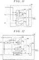
- the hysteresis control circuit 83 includes a control amount calculation circuit 141, a gain calculation circuit 142, and a multiplier 143.
- the control amount calculation circuit 141 calculates the hysteresis control amount I 3 * by using a map that defines a relationship between the steering angle ⁇ s and the hysteresis control amount I 3 *.
- the hysteresis control amount I 3 * has a hysteresis characteristic for the steering angle ⁇ s .
- the hysteresis characteristic in the map is set from the viewpoint of optimizing a hysteresis characteristic caused by friction in a mechanical transmission system of the steering system 10.
- the control amount calculation circuit 141 may calculate the hysteresis control amount I 3 * in consideration of the vehicle speed V.
- the gain calculation circuit 142 calculates a gain G7 by using a map that defines a relationship between the axial force deviation ⁇ F and the gain G7 depending on the vehicle speed V.
- the gain G7 is set to a larger value as the axial force deviation ⁇ F increases.
- the multiplier 143 calculates a final hysteresis control amount I 3 * by multiplying the hysteresis control amount I 3 * calculated by the control amount calculation circuit 141 and the gain G7 together.
- the gain G7 reflects the axial force deviation ⁇ F, and therefore the final hysteresis control amount I 3 * also reflects the axial force deviation ⁇ F.
- the hysteresis control amount I 3 * is changed in response to the axial force deviation ⁇ F between the ideal axial force F i and the estimated axial force F e , thereby attaining a more appropriate hysteresis control amount I 3 * (final) based on the road condition.
- a steering feel sense of friction in this case
- the driver feels the steering reaction force applied to the steering wheel 11 as tactile feedback, and can therefore grasp the sense of friction based on the road condition more accurately.
- the final hysteresis control amount I 3 * has a larger value as the axial force deviation ⁇ F increases along with a decrease in the road grip of the tire. This is because a gain G7 having a larger value is calculated as the axial force deviation ⁇ F increases. Therefore, the target steering reaction force T 1 * decreases by an amount corresponding to the hysteresis control amount I 3 * subtracted from the basic control amount I 1 *. That is, the steering reaction force to be applied to the steering shaft 12 decreases by an amount corresponding to the subtraction of the hysteresis control amount I 3 *.
- a steering feel sense of friction in this case
- the driver can grasp a decrease in the sense of friction as the steering feel. Furthermore, the driver can grasp, as tactile feedback, a situation in which the road grip of the tire decreases.
- the ideal axial force calculation circuit 91 may have the following configuration. As illustrated in FIG. 12 , the ideal axial force calculation circuit 91 includes an absolute value calculation circuit 144, an axial force calculation circuit 145, a sign calculation circuit 146, a hysteresis calculation circuit 147, a multiplier 148, and an adder 149.
- the absolute value calculation circuit 144 calculates an absolute value
- the axial force calculation circuit 145 calculates the ideal axial force F i by using a map that defines a relationship between the absolute value
- the ideal axial force F i is set to a larger value as the absolute value
- the sign calculation circuit 146 calculates a sign S based on the target pinion angle ⁇ p *. Specifically, Conditions (A1) to (A3) below are applied.
- the hysteresis calculation circuit 147 has a calculation function similar to that of the hysteresis control circuit 83 illustrated in FIG. 11 . That is, the hysteresis calculation circuit 147 calculates the hysteresis control amount I 3 * (final) based on the steering angle ⁇ s , the vehicle speed V, and the axial force deviation ⁇ F.
- the multiplier 148 multiplies the ideal axial force F i calculated by the axial force calculation circuit 145 and the sign S calculated by the sign calculation circuit 146 together.
- the adder 149 calculates a final ideal axial force F i by adding the ideal axial force F i multiplied by the sign S and the hysteresis control amount I 3 * calculated by the hysteresis calculation circuit 147 together.
- the final ideal axial force F i is even closer to the actual axial force (estimated axial force).
- the final axial force F sp calculated by the axial force blending calculation circuit 95 reflects the estimated axial force with higher superiority to the ideal axial force F i .
- the target steering reaction force calculation circuit 51 has the following configuration.
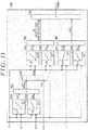
- the steering wheel return control circuit 84 includes a target speed calculation circuit 151, four gain calculation circuits 152, 156, 157, and 158, four multipliers 153, 159, 160, and 161, a subtractor 154, and a control amount calculation circuit 155.
- the target speed calculation circuit 151 calculates a target speed ⁇ s * by using a map that defines a relationship between the steering angle ⁇ s and the target speed ⁇ s * depending on the vehicle speed V.
- the target speed ⁇ s * is a target value of a speed when the steering wheel 11 is returned to its neutral position.
- the target speed ⁇ s * is set to a larger value as the steering angle ⁇ s (absolute value) increases.
- the gain calculation circuit 152 calculates a gain G8 by using a map that defines a relationship between the axial force deviation ⁇ F and the gain G8 depending on the vehicle speed V.
- the gain G8 is set to a larger value as the axial force deviation ⁇ F increases.
- the multiplier 153 calculates a final target speed ⁇ s * by multiplying the target speed ⁇ s * and the gain G8 together.
- the gain G8 reflects the axial force deviation ⁇ F, and therefore the final target speed ⁇ s * also reflects the axial force deviation ⁇ F.
- the subtractor 154 calculates a speed deviation ⁇ s by subtracting the steering speed ⁇ s from the final target speed ⁇ s *.
- the control amount calculation circuit 155 calculates the steering wheel return control amount I 4 * by using a map that defines a relationship between the speed deviation ⁇ s and the steering wheel return control amount I 4 * depending on the vehicle speed V.
- the steering wheel return control amount I 4 * is set to a larger value as the speed deviation ⁇ s increases.
- the gain calculation circuit 156 calculates a gain G9 by using a map that defines a relationship between the axial force deviation ⁇ F and the gain G9 depending on the vehicle speed V.
- the gain G9 is set to a larger value as the axial force deviation ⁇ F increases.
- the gain calculation circuit 157 calculates a gain G10 by using a map that defines a relationship between the steering torque T h and the gain G10 depending on the vehicle speed V.
- the gain G10 is set to a smaller value as the steering torque T h increases.
- the gain calculation circuit 158 calculates a gain G11 by using a map that defines a relationship between the axial force deviation ⁇ F and the gain G11 depending on the vehicle speed V.
- the gain G11 is set to a larger value as the axial force deviation ⁇ F increases.
- the multiplier 159 multiplies the steering wheel return control amount I 4 * and the gain G9 together.
- the gain G9 reflects the axial force deviation ⁇ F, and therefore the steering wheel return control amount I 4 * multiplied by the gain G9 has a value based on the axial force deviation ⁇ F.
- the multiplier 160 calculates a gain G12 by multiplying the gain G10 and the gain G11 together. That is, the gain G10 based on the steering torque T h is changed in response to the axial force deviation ⁇ F.
- the multiplier 161 calculates a final steering wheel return control amount I 4 * by multiplying the steering wheel return control amount I 4 * multiplied by the gain G9 and the gain G12 together.
- the steering wheel return control amount I 4 * is changed in response to the axial force deviation ⁇ F, thereby attaining a more appropriate steering wheel return control amount I 4 * based on the road condition.
- a steering wheel return control amount I 4 * having a larger value is calculated as the axial force deviation ⁇ F increases due to a decrease in the road grip of the tire.
- the steering wheel return performance in the tire grip limit range can be improved.
- the fourth embodiment may be modified as follows.
- the steering wheel return control circuit 84 may have a configuration provided only with the control amount calculation circuit 155, the gain calculation circuit 156, and the multiplier 159. That is, the target speed calculation circuit 151, the gain calculation circuits 152, 157, and 158, the multipliers 153, 160, and 161, and the subtractor 154 are omitted from the steering wheel return control circuit 84 illustrated in FIG. 13 .
- the control amount calculation circuit 155 calculates the steering wheel return control amount I 4 * by using a map that defines a relationship between the steering angle ⁇ s and the steering wheel return control amount I 4 * depending on the vehicle speed V.
- the multiplier 159 calculates the final steering wheel return control amount I 4 * by multiplying the steering wheel return control amount I 4 * calculated by the control amount calculation circuit 155 and the gain G9 calculated by the gain calculation circuit 156 together.
- the target steering reaction force calculation circuit 51 has the following configuration.
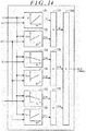
- the damping control circuit 85 includes a control amount calculation circuit 171, five gain calculation circuits 172, 173, 174, 175, and 176, and four multipliers 177, 178, 179, and 180.
- the control amount calculation circuit 171 calculates the damping control amount I 5 * by using a map that defines a relationship between the steering speed ⁇ s and the damping control amount I 5 * depending on the vehicle speed V.
- the damping control amount I 5 * is set to a larger value as the steering speed ⁇ s increases.
- the gain calculation circuit 172 calculates a gain G13 by using a map that defines a relationship between the axial force deviation ⁇ F and the gain G13 depending on the vehicle speed V.
- the gain G13 is set to a larger value as the axial force deviation ⁇ F increases.
- the gain calculation circuit 173 calculates a gain G14 by using a map that defines a relationship between the steering angle ⁇ s and the gain G14 depending on the vehicle speed V.
- the gain G14 is set to a smaller value as the steering angle ⁇ s (absolute value) increases.
- the gain calculation circuit 174 calculates a gain G15 by using a map that defines a relationship between the axial force deviation ⁇ F and the gain G15 depending on the vehicle speed V. A gain G15 having a larger value is calculated as the axial force deviation ⁇ F increases.
- the gain calculation circuit 175 calculates a gain G16 by using a map that defines a relationship between the steering torque T h and the gain G16 depending on the vehicle speed V.
- the gain G16 is set to a smaller value as the steering torque T h (absolute value) increases.
- the gain calculation circuit 176 calculates a gain G17 by using a map that defines a relationship between the axial force deviation ⁇ F and the gain G17 depending on the vehicle speed V.
- the gain G17 is set to a larger value as the axial force deviation ⁇ F increases.
- the multiplier 177 multiplies the damping control amount I 5 * calculated by the control amount calculation circuit 171 and the gain G13 calculated by the gain calculation circuit 172 together.
- the multiplier 178 calculates a gain G18 by multiplying the gain G14 and the gain G15 together.
- the multiplier 179 calculates a gain G19 by multiplying the gain G16 and the gain G17 together.
- the multiplier 180 calculates a final damping control amount I 5 * by multiplying the damping control amount I 5 * multiplied by the gain G13, the gain G18, and the gain G19 together.
- the damping control amount I 5 * is changed in response to the axial force deviation ⁇ F between the ideal axial force F i and the estimated axial force F e , thereby attaining a more appropriate damping control amount I 5 * (final) based on the road condition.
- a more appropriate steering reaction force in response to the road condition is applied to the steering wheel 11.
- the driver feels the steering reaction force applied to the steering wheel 11 as tactile feedback, and can therefore grasp the road condition more accurately.
- the final damping control amount I 5 * has a larger value as the axial force deviation ⁇ F increases along with a decrease in the road grip of the tire. This is because a gain G13 having a larger value is calculated as the axial force deviation ⁇ F increases. Therefore, the target steering reaction force T 1 * decreases by an amount corresponding to the increase in the damping control amount I 5 * subtracted from the basic control amount I 1 * . That is, the steering reaction force to be applied to the steering shaft 12 decreases by an amount corresponding to the increase in the damping control amount I 5 *.
- a steering feel sense of viscosity in this case
- the driver can grasp a decrease in the sense of viscosity as the steering feel. Furthermore, the driver can grasp, as tactile feedback, a situation in which the road grip of the tire decreases.
- the damping control amount I 5 * is adjusted by being multiplied by the gain G14 based on the steering angle ⁇ s and the gain G16 based on the steering torque T h .
- the gains G14 and G16 are also changed in response to the axial force deviation ⁇ F.
- a more appropriate damping control amount I 5 * based on the road condition can be attained.
- EPS electric power steering system
- an EPS 190 includes the steering shaft 12, the pinion shaft 13, and the steering operation shaft 14 that function as the power transmission path between the steering wheel 11 and each of the steered wheels 16 and 16. Reciprocating linear motion of the steering operation shaft 14 is transmitted to the right and left steered wheels 16 and 16 via the tie rods 15 coupled to both ends of the steering operation shaft 14, respectively.
- the EPS 190 includes an assist motor 191, a speed reducing mechanism 192, the torque sensor 34, a rotation angle sensor 193, and a control apparatus 194 as a structure for generating a steering assist force (assist force).
- the rotation angle sensor 193 is provided on the assist motor 191 to detect its rotation angle ⁇ m .
- the assist motor 191 is a source of the steering assist force.
- a three-phase brushless motor is employed as the assist motor 191.
- the assist motor 191 is coupled to the pinion shaft 13 via the speed reducing mechanism 192.
- the speed of rotation of the assist motor 191 is reduced by the speed reducing mechanism 192, and a rotational force obtained through the speed reduction is transmitted to the pinion shaft 13 as the steering assist force.
- the control apparatus 194 executes assist control for generating a steering assist force based on the steering torque T h through energization control for the assist motor 191.
- the control apparatus 194 controls power supply to the assist motor 191 based on the steering torque T h detected through the torque sensor 34, the vehicle speed V detected through the vehicle speed sensor 501, and the rotation angle ⁇ m detected through the rotation angle sensor 193.
- the control apparatus 194 includes a pinion angle calculation circuit 201, a basic assist component calculation circuit 202, a target pinion angle calculation circuit 203, a pinion angle feedback control circuit (pinion angle F/B control circuit) 204, an adder 205, and an energization control circuit 206.
- the pinion angle calculation circuit 201 acquires the rotation angle ⁇ m of the assist motor 191, and calculates a pinion angle ⁇ p that is the rotation angle of the pinion shaft 13 based on the acquired rotation angle ⁇ m .
- the basic assist component calculation circuit 202 basically has a configuration similar to that of the target steering reaction force calculation circuit 51 illustrated in FIG. 3 . That is, the basic assist component calculation circuit 202 includes the basic control circuit 81, the system stabilization control circuit 82, the hysteresis control circuit 83, the steering wheel return control circuit 84, the damping control circuit 85, and the calculator 86.
- the calculator 86 calculates a basic assist component T a1 * (current value) by adding the stabilization control amount I 2 * and the steering wheel return control amount I 4 * to the basic control amount I 1 * and subtracting the hysteresis control amount I 3 * and the damping control amount I 5 * from the basic control amount I 1 *.
- the increase/decrease characteristic of the map that is used in the gain calculation circuit 122 (see FIG. 7 ) of the basic control circuit 81 is set opposite to the characteristic of the first embodiment. That is, the gain calculation circuit 122 calculates a gain G2 having a larger value as the axial force deviation ⁇ F increases.
- the target pinion angle calculation circuit 203 acquires the basic assist component T a1 * calculated by the basic assist component calculation circuit 202 and the steering torque T h .
- the target pinion angle calculation circuit 203 has an ideal model that defines an ideal pinion angle based on a basic drive torque (input torque), which is the total sum of the basic assist component T a1 * and the steering torque T h .
- the ideal model is obtained by modeling a pinion angle corresponding to an ideal steered angle based on the basic drive torque through an experiment or the like in advance.
- the target pinion angle calculation circuit 203 determines the basic drive torque by adding the basic assist component T a1 * and the steering torque T h together, and calculates a target pinion angle ⁇ p * from the determined basic drive torque based on the ideal model.
- the target pinion angle calculation circuit 203 calculates the target pinion angle ⁇ p *, the vehicle speed V and a current value I m are taken into consideration.
- the current value I m is detected through a current sensor 207 provided in a power supply path to the assist motor 191.
- the current value I m is a value of an actual current supplied to the assist motor 191.
- the pinion angle feedback control circuit 204 acquires the target pinion angle ⁇ p * calculated by the target pinion angle calculation circuit 203 and the actual pinion angle ⁇ p calculated by the pinion angle calculation circuit 201.
- the pinion angle feedback control circuit 204 performs proportional-integral-derivative (PID) control as feedback control for the pinion angle so that the actual pinion angle ⁇ p follows the target pinion angle ⁇ p *. That is, the pinion angle feedback control circuit 204 determines a deviation between the target pinion angle ⁇ p * and the actual pinion angle ⁇ p , and calculates a correction component T a2 * for the basic assist component T a1 * so as to eliminate the deviation.
- PID proportional-integral-derivative
- the adder 205 calculates an assist command value T a * by adding the correction component T a2 * to the basic assist component T a1 *.
- the assist command value T a * is a command value indicating a rotational force (assist torque) to be generated in the assist motor 191.
- the energization control circuit 206 supplies electric power to the assist motor 191 based on the assist command value T a *. Specifically, the energization control circuit 206 calculates a current command value for the assist motor 191 based on the assist command value T a *. The energization control circuit 206 acquires the current value I m detected through the current sensor 207. Then, the energization control circuit 206 determines a deviation between the current command value and the actual current value I m , and controls power supply to the assist motor 191 so as to eliminate the deviation. Thus, the assist motor 191 generates a torque based on the assist command value T a *. As a result, the steering is assisted based on the steering condition.
- the target pinion angle ⁇ p * is set based on the ideal model from the basic drive torque (total sum of the basic assist component T a1 * and the steering torque T h ), and feedback control is performed so that the actual pinion angle ⁇ p equals the target pinion angle ⁇ p *.
- the actual steered angle ⁇ t is kept as a steered angle ⁇ t based on the target pinion angle ⁇ p *. Therefore, there is attained an effect of suppressing a reverse input vibration that may be caused by a disturbance due to a road condition, braking, or the like. That is, even if a vibration is transmitted to a steering mechanism such as the steering shaft 12 via the steered wheels 16 and 16, the correction component T a2 * is adjusted so that the pinion angle ⁇ p equals the target pinion angle ⁇ p *. Therefore, the actual steered angle ⁇ t is kept as a steered angle ⁇ t based on the target pinion angle ⁇ p * defined by the ideal model. Consequently, the transmission of the reverse input vibration to the steering wheel 11 is suppressed by assisting the steering in a direction in which the reverse input vibration is canceled.
- the steering reaction force (tactile feedback to be acquired through a steering operation), which is a force (torque) to be applied in a direction opposite to the driver's steering direction, is only based on the target pinion angle ⁇ p *. That is, the steering reaction force does not change in response to a road condition such as a dry road or a low-friction road. Therefore, it is difficult for the driver to grasp the road condition as tactile feedback.
- the calculation function of the target steering angle calculation circuit 52 of the first embodiment is provided to, for example, the target pinion angle calculation circuit 203.
- the target pinion angle calculation circuit 203 has a functional configuration similar to that of the target steering angle calculation circuit 52 illustrated in FIG. 4 .
- the target steering angle calculation circuit 52 acquires the target steering reaction force T 1 *, whereas the target pinion angle calculation circuit 203 of this example acquires the basic assist component T a1 *.
- the target steering angle calculation circuit 52 acquires the current value I b of the current supplied to the steering operation motor 41, whereas the target pinion angle calculation circuit 203 of this example acquires the current value I m of the current supplied to the assist motor 191.
- the target pinion angle calculation circuit 203 acquires the steering torque T h and the vehicle speed V similarly to the target steering angle calculation circuit 52.
- the target steering angle calculation circuit 52 calculates the target steering angle ⁇ *, whereas the target pinion angle calculation circuit 203 of this example calculates the target pinion angle ⁇ p *. Although a part of the signals to be acquired and the signal to be generated are different, details of internal calculation processing of the target pinion angle calculation circuit 203 are the same as those of the target steering angle calculation circuit 52.
- the basic control amount I 1 * is changed in response to the axial force deviation ⁇ F between the ideal axial force F i and the estimated axial force F e , thereby calculating a basic assist component T a1 * that reflects the road condition (such as a road frictional resistance) more appropriately.
- a more appropriate assist force in response to the road condition is applied to the steering wheel 11.
- the driver feels the steering reaction force via the steering wheel 11 as tactile feedback, and can therefore grasp the road condition more accurately.
- the gain G2 calculated by the gain calculation circuit 122 is set to a larger value as the axial force deviation ⁇ F increases along with a decrease in the road grip of the tire. Therefore, the basic control amount I 1 * and furthermore the basic assist component T a1 * have larger values. Thus, a more appropriate (greater) assist force in response to the road grip of the tire is applied to the steering wheel 11.
- the driver can grasp, as tactile feedback, a situation in which the road grip of the tire decreases.
- the sixth embodiment may be modified as follows.
- the calculation functions of the target steering reaction force calculation circuit 51 of the second to fifth embodiments may be provided to the basic assist component calculation circuit 202. Also in this case, effects similar to those of the second to fifth embodiments can be attained.
- the electric power steering system (EPS) 190 configured to apply a steering assist force to the steering operation shaft 14 is taken as an example, but another type of EPS configured to apply a steering assist force to the steering shaft may be employed instead. Details are as follows.
- the assist motor 191 is coupled to the steering shaft 12 instead of the steering operation shaft 14 via the speed reducing mechanism 192.
- the pinion shaft 44 may be omitted.
- the control apparatus 194 executes feedback control for the steering angle ⁇ s instead of the feedback control for the pinion angle ⁇ p .
- the pinion angle calculation circuit 201 functions as a steering angle calculation circuit configured to calculate a steering angle ⁇ s based on the current value I m of the assist motor 191.
- the target pinion angle calculation circuit 203 functions as a target steering angle calculation circuit configured to calculate a target steering angle that is a target value of the steering angle ⁇ s based on the steering torque T h , the vehicle speed V, the basic assist component T a1 *, and the current value I m .
- the target steering angle calculation circuit basically has a configuration similar to that of the target steering angle calculation circuit 52 illustrated in FIG. 4 .
- the differentiator 79 provided in the control apparatus 194 calculates a steering speed ⁇ s by differentiating the steering angle ⁇ s .
- the pinion angle feedback control circuit 204 functions as a steering angle feedback control circuit configured to determine a deviation between the target steering angle and the actual steering angle ⁇ s , and calculate a correction component T a2 * for the basic assist component T a1 * so as to eliminate the deviation.
- the embodiments may be modified as follows.
- the torque sensor 34 is provided on the steering shaft 12, but may be provided on the pinion shaft 13.
- the position where the torque sensor 34 is provided is not limited as long as the steering torque T h can be detected.
- the steer-by-wire type steering system 10 may have a configuration in which the clutch 21 is omitted.
- the control apparatus 50 may have a configuration in which the differentiation steering control circuit 63 is omitted.
- the pinion angle feedback control circuit 64 acquires the target pinion angle ⁇ p * calculated by the steering angle ratio change control circuit 62, and executes feedback control for the pinion angle ⁇ p so that the actual pinion angle ⁇ p follows the acquired target pinion angle ⁇ p *.
- the control apparatus 50 may have a configuration in which both the differentiation steering control circuit 63 and the steering angle ratio change control circuit 62 are omitted.
- the target steering angle ⁇ * calculated by the target steering angle calculation circuit 52 is directly used as the target pinion angle ( ⁇ p *). That is, the steered wheels 16 and 16 are turned by an amount corresponding to the operation of the steering wheel 11.
- the basic control circuit 81 calculates the basic control amount I 1 * by multiplying the steering torque T h and the gain G1 together, but may be configured as follows. That is, the basic control circuit 81 calculates the basic control amount I 1 * by using a three-dimensional map that defines a relationship between the steering torque T h and the basic control amount I 1 * depending on the vehicle speed V. The basic control circuit 81 sets the absolute value of the basic control amount I 1 * to a larger value as the absolute value of the steering torque T h increases and as the vehicle speed V decreases.
- the vehicle model 72 may have a configuration in which at least one of the two estimated axial force calculation circuits 93 and 94 is omitted. That is, the axial force F pre may be calculated by summing up at least the axial force F1 (estimated axial force) estimated and calculated by the estimated axial force calculation circuit 92 and the ideal axial force F i at a predetermined blending ratio. The final axial force F sp is calculated by summing up the axial force F pre and the imaginary rack end axial force F end .
- the blending ratio D j of the estimated axial force F e calculated by the first calculation circuit 95a may be determined by using at least one of the blending ratios Dcc, D d , D e , D f , D g , D h , and D i calculated by the respective blending ratio calculation circuits (108 to 114).
- the one blending ratio is directly used as the blending ratio D j of the estimated axial force F e .
- the vehicle speed V need not be taken into consideration in the maps that are used in the gain calculation circuits 122, 133, 142, 152, 156, 158, 172, 174, and 176 configured to calculate gains based on the axial force deviation ⁇ F.
- the gain calculation circuits 122, 133, 142, 152, 156, 158, 172, 174, and 176 calculate gains by using the axial force deviation ⁇ F that is a difference between the ideal axial force F i and the estimated axial force F e , but a difference between one of the following axial forces (B1) to (B4) and the ideal axial force F i may be used as the axial force deviation ⁇ F.
- the subtractor 107 illustrated in FIG. 6 may acquire the axial force F1, the axial force F2, the axial force F3, or the axial force F c in place of the estimated axial force F e .
- a subtractor 107a may be added to the axial force blending calculation circuit 95, and the added subtractor 107a may calculate a difference between the ideal axial force F i and the axial force F1, the axial force F2, the axial force F3, or the axial force F c .
- FIG. 6 illustrates an example in which the added subtractor 107a acquires the axial force F1.
Landscapes
- Engineering & Computer Science (AREA)
- Chemical & Material Sciences (AREA)
- Combustion & Propulsion (AREA)
- Transportation (AREA)
- Mechanical Engineering (AREA)
- Physics & Mathematics (AREA)
- Mathematical Physics (AREA)
- Steering Control In Accordance With Driving Conditions (AREA)
- Power Steering Mechanism (AREA)
Abstract
Description
- The present invention relates to a vehicle control apparatus.
- Hitherto, there is known a so-called steer-by-wire type steering system in which a steering wheel and steered wheels are mechanically separated from each other. This steering system includes a reaction motor and a steering operation motor. The reaction motor is a source of a steering reaction force to be applied to a steering shaft. The steering operation motor is a source of a steering operation force for turning the steered wheels. When a vehicle is traveling, a control apparatus of the steering system generates the steering reaction force through the reaction motor, and turns the steered wheels through the steering operation motor.
- In the steer-by-wire type steering system, it is not likely that a road reaction force applied to the steered wheels is transmitted to the steering wheel because the steering wheel and the steered wheels are mechanically separated from each other. Thus, it is difficult for the driver to grasp a road condition as the steering reaction force (tactile feedback) that may be felt by the hands through the steering wheel.
- For example, a control apparatus described in Japanese Patent Application Publication No.
2014-148299 JP 2014-148299 A - The driver is informed of accurate road information through the steering wheel as tactile feedback, and can therefore perform a steering operation more quickly and more accurately. Further, a feeling of security in driving is enhanced. Therefore, a further improvement is desired for informing the driver of the road condition more appropriately as the steering reaction force (tactile feedback).
- It is one object of the present invention to provide a vehicle control apparatus capable of informing a driver of a road condition more appropriately as a steering reaction force.
- A vehicle control apparatus according to one aspect of the present invention is a vehicle control apparatus configured to control a motor based on a command value to be calculated based on a steering condition. The motor is a source of a driving force to be applied to a steering mechanism of a vehicle. The vehicle control apparatus includes a first calculation circuit, a second calculation circuit, and a third calculation circuit. The first calculation circuit is configured to calculate a first component of the command value based on at least a steering torque. The second calculation circuit is configured to calculate a target rotation angle of a rotating body based on a basic drive torque, which is a total sum of the steering torque and the first component. The rotating body is configured to rotate in association with a turning operation of a steered wheel. The third calculation circuit is configured to calculate a second component of the command value through feedback control performed so that an actual rotation angle of the rotating body equals the target rotation angle.
- The second calculation circuit includes an ideal axial force calculation circuit, an estimated axial force calculation circuit, a blending calculation circuit, and a subtractor. The ideal axial force calculation circuit is configured to calculate an ideal axial force based on the target rotation angle. The estimated axial force calculation circuit is configured to calculate, as an estimated axial force, an axial force applied to the steered wheel based on a state variable that reflects vehicle behavior or a road condition. The blending calculation circuit is configured to calculate a final axial force to be reflected in the basic drive torque as a reaction force component for the basic drive torque by summing up a value obtained by multiplying the ideal axial force by a blending ratio and a value obtained by multiplying the estimated axial force by a blending ratio. The blending ratios are set individually based on the state variable that reflects the vehicle behavior or the road condition or based on the steering condition. The subtractor is configured to calculate an axial force deviation, which is a difference between the ideal axial force and the estimated axial force. The first calculation circuit is configured to change the first component of the command value in response to the axial force deviation.
- The axial force deviation between the ideal axial force and the estimated axial force reflects the road condition. For example, when the vehicle is traveling along a low-friction road, the axial force deviation is likely to occur between the ideal axial force and the estimated axial force. The axial force deviation has a larger value as a road grip decreases. According to the configuration described above, the first component of the command value for the motor is changed in response to the axial force deviation, thereby calculating a command value that reflects the road condition more appropriately. Therefore, the motor generates a driving force that reflects the road condition more appropriately. Thus, the driver can acquire a more appropriate steering reaction force in response to the road condition as tactile feedback.
- In the vehicle control apparatus of the aspect described above, the first calculation circuit may include a basic control amount calculation circuit, a compensation amount calculation circuit, and a calculator. The basic control amount calculation circuit is configured to calculate a basic control amount based on the steering condition. The basic control amount is a fundamental component of the first component of the command value. The compensation amount calculation circuit is configured to calculate a compensation amount for the fundamental component based on the steering condition. The calculator is configured to calculate the first component of the command value by summing up the fundamental component and the compensation amount. In this case, the first component of the command value may be changed by the basic control amount calculation circuit changing the basic control amount in response to the axial force deviation or the compensation amount calculation circuit changing the compensation amount in response to the axial force deviation.
- In the vehicle control apparatus of the aspect described above, when it is assumed that the compensation amount calculation circuit changes the compensation amount in response to the axial force deviation, the compensation amount calculation circuit may include a stabilization control amount calculation circuit configured to calculate, based on the steering condition, a stabilization control amount for stabilizing a system. In this case, the first component of the command value may be changed by the stabilization control amount calculation circuit changing the stabilization control amount in response to the axial force deviation. According to this configuration, the stabilization control amount is changed in response to the axial force deviation, thereby securing the system stability more appropriately based on the road condition.
- In the vehicle control apparatus of the aspect described above, when it is assumed that the compensation amount calculation circuit changes the compensation amount in response to the axial force deviation, the compensation amount calculation circuit may include a hysteresis control amount calculation circuit configured to calculate, based on the steering condition, a hysteresis control amount for compensating a hysteresis characteristic caused by friction during a steering operation. In this case, the first component of the command value may be changed by the hysteresis control amount calculation circuit changing the hysteresis control amount in response to the axial force deviation. According to this configuration, the hysteresis control amount is changed in response to the axial force deviation, thereby attaining a sense of friction based on the road condition.
- In the vehicle control apparatus of the aspect described above, when it is assumed that the compensation amount calculation circuit changes the compensation amount in response to the axial force deviation, the compensation amount calculation circuit may include a steering wheel return control amount calculation circuit configured to calculate, based on the steering condition, a steering wheel return control amount for compensating a steering wheel return characteristic. In this case, the first component of the command value may be changed by the steering wheel return control amount calculation circuit changing the steering wheel return control amount in response to the axial force deviation. According to this configuration, the steering wheel return control amount is changed in response to the axial force deviation, thereby attaining a steering wheel return characteristic based on the road condition.
- In the vehicle control apparatus of the aspect described above, when it is assumed that the compensation amount calculation circuit changes the compensation amount in response to the axial force deviation, the compensation amount calculation circuit may include a damping control amount calculation circuit configured to calculate, based on the steering condition, a damping control amount for compensating a viscosity of the steering mechanism. In this case, the first component of the command value may be changed by the damping control amount calculation circuit changing the damping control amount in response to the axial force deviation. According to this configuration, the damping control amount is changed in response to the axial force deviation, thereby attaining a sense of viscosity based on the road condition.
- In the vehicle control apparatus of the aspect described above, the steering mechanism may include a steering operation shaft configured to turn the steered wheel by applying a steering operation force generated by a steering operation motor. The estimated axial force may be one of the following estimated axial forces:
- a. a first estimated axial force calculated based on a current value of the steering operation motor;
- b. a second estimated axial force calculated based on a lateral acceleration applied to the vehicle;
- c. a third estimated axial force calculated based on a yaw rate, which is a speed at which the vehicle makes a turn;
- d. a fourth estimated axial force obtained by summing up a value obtained by multiplying the second estimated axial force by a blending ratio and a value obtained by multiplying the third estimated axial force by a blending ratio, the blending ratios being set individually based on the vehicle behavior; and
- e. a fifth estimated axial force obtained by summing up a value obtained by multiplying the first estimated axial force by a blending ratio, a value obtained by multiplying the second estimated axial force by a blending ratio, and a value obtained by multiplying the third estimated axial force by a blending ratio, the blending ratios being set individually based on the vehicle behavior.
- Depending on product specifications or the like, the estimated axial force to be used for calculating the axial force deviation is changed as appropriate.
- In the vehicle control apparatus of the aspect described above, the steering mechanism may include a pinion shaft and a steering operation shaft. The pinion shaft serves as the rotating body and is mechanically separated from a steering wheel. The steering operation shaft is configured to turn the steered wheel in association with rotation of the pinion shaft. The steering mechanism may include a reaction motor and a steering operation motor as control targets of the vehicle control apparatus. The reaction motor serves as the motor and is configured to generate, based on the command value, a steering reaction force as the driving force to be applied to the steering wheel. The steering reaction force is a torque in a direction opposite to a steering direction. The steering operation motor is configured to generate a steering operation force for turning the steered wheel. The steering operation force is applied to the pinion shaft or the steering operation shaft.
- In the vehicle control apparatus of the aspect described above, the steering mechanism may include a pinion shaft and a steering operation shaft. The pinion shaft serves as the rotating body and is configured to operate in association with a steering wheel. The steering operation shaft is configured to turn the steered wheel in association with rotation of the pinion shaft. The motor may be an assist motor configured to generate a steering assist force as the driving force to be applied to the steering wheel. The steering assist force is a torque in a direction identical to a steering direction.
- The foregoing and further features and advantages of the invention will become apparent from the following description of example embodiments with reference to the accompanying drawings, wherein like numerals are used to represent like elements and wherein:
-
FIG. 1 is a configuration diagram of a steer-by-wire type steering system on which a vehicle control apparatus according to a first embodiment is mounted; -
FIG. 2 is a control block diagram of an electronic control apparatus according to the first embodiment; -
FIG. 3 is a control block diagram of a target steering reaction force calculation circuit according to the first embodiment; -
FIG. 4 is a control block diagram of a target steering angle calculation circuit according to the first embodiment; -
FIG. 5 is a control block diagram of a vehicle model according to the first embodiment; -
FIG. 6 is a control block diagram of an axial force blending calculation circuit according to the first embodiment; -
FIG. 7 is a control block diagram of a basic control circuit according to the first embodiment; -
FIG. 8 is a control block diagram of a basic control circuit according to a second embodiment; -
FIG. 9 is a graph illustrating a relationship between a steering torque and a basic control amount according to the second embodiment; -
FIG. 10 is a control block diagram of a system stabilization control circuit according to the second embodiment; -
FIG. 11 is a control block diagram of a hysteresis control circuit according to a third embodiment; -
FIG. 12 is a control block diagram of an ideal axial force calculation circuit according to the third embodiment; -
FIG. 13 is a control block diagram of a steering wheel return control circuit according to a fourth embodiment; -
FIG. 14 is a control block diagram of a damping control circuit according to a fifth embodiment; -
FIG. 15 is a configuration diagram of a steering system (electric power steering system) according to a sixth embodiment; and -
FIG. 16 is a control block diagram of an electronic control apparatus according to the sixth embodiment. - Description is given of a vehicle control apparatus according to a first embodiment of the present invention, which is applied to a steer-by-wire type steering system.
- As illustrated in
FIG. 1 , asteering system 10 for a vehicle includes a steeringshaft 12 coupled to asteering wheel 11. Apinion shaft 13 is provided at the end of the steeringshaft 12 that is located opposite to thesteering wheel 11.Pinion teeth 13a of thepinion shaft 13 mesh withrack teeth 14a of asteering operation shaft 14 extending in a direction that intersects thepinion shaft 13. Right and left steeredwheels steering operation shaft 14 viatie rods shaft 12, thepinion shaft 13, and thesteering operation shaft 14 function as a power transmission path between thesteering wheel 11 and each of the steeredwheels steering operation shaft 14 performs linear motion along with a rotational operation of thesteering wheel 11, thereby changing a steered angle θt of each of the steeredwheels - The
steering system 10 includes a clutch 21. The clutch 21 is provided on the steeringshaft 12. An electromagnetic clutch is employed as the clutch 21. The electromagnetic clutch connects and disconnects power through connection and disconnection of electric power for an exciting coil. When the clutch 21 is disengaged, the power transmission path between thesteering wheel 11 and each of the steeredwheels steering wheel 11 and each of the steeredwheels - The
steering system 10 includes areaction motor 31, aspeed reducing mechanism 32, arotation angle sensor 33, and atorque sensor 34 as a structure for generating a steering reaction force (reaction unit). The steering reaction force is a force (torque) to be applied in a direction opposite to a direction of a driver's operation of thesteering wheel 11. By applying the steering reaction force to thesteering wheel 11, the driver can acquire appropriate tactile feedback. - The
reaction motor 31 is a source of the steering reaction force. For example, a three-phase (U, V, W) brushless motor is employed as thereaction motor 31. The reaction motor 31 (to be exact, its rotation shaft) is coupled to the steeringshaft 12 via thespeed reducing mechanism 32. Thespeed reducing mechanism 32 is provided at a part of the steeringshaft 12 that is located on thesteering wheel 11 side with respect to the clutch 21. A torque of thereaction motor 31 is applied to the steeringshaft 12 as the steering reaction force. - The
rotation angle sensor 33 is provided on thereaction motor 31. Therotation angle sensor 33 detects a rotation angle θa of thereaction motor 31. The rotation angle θa of thereaction motor 31 is used for calculating a steering angle θs. Thereaction motor 31 and the steeringshaft 12 operate in association with each other via thespeed reducing mechanism 32. Therefore, the rotation angle θa of thereaction motor 31 is correlated to the steering angle θs that is a rotation angle of the steeringshaft 12 and furthermore a rotation angle of thesteering wheel 11. Thus, the steering angle θs can be determined based on the rotation angle θa of thereaction motor 31. - The
torque sensor 34 detects a steering torque Th applied to the steeringshaft 12 through a rotational operation of thesteering wheel 11. Thetorque sensor 34 is provided at a part of the steeringshaft 12 that is located on thesteering wheel 11 side with respect to thespeed reducing mechanism 32. - The
steering system 10 includes asteering operation motor 41, aspeed reducing mechanism 42, and arotation angle sensor 43 as a structure for generating a steering operation force (steering operation unit) that is power for turning the steeredwheels - The
steering operation motor 41 is a source of the steering operation force. For example, a three-phase brushless motor is employed as thesteering operation motor 41. The steering operation motor 41 (to be exact, its rotation shaft) is coupled to apinion shaft 44 via thespeed reducing mechanism 42.Pinion teeth 44a of thepinion shaft 44 mesh withrack teeth 14b of thesteering operation shaft 14. A torque of thesteering operation motor 41 is applied to thesteering operation shaft 14 via thepinion shaft 44 as the steering operation force. In response to rotation of thesteering operation motor 41, thesteering operation shaft 14 moves along a vehicle width direction (lateral direction inFIG. 1 ). Therotation angle sensor 43 is provided on thesteering operation motor 41. Therotation angle sensor 43 detects a rotation angle θb of thesteering operation motor 41. - The
steering system 10 includes acontrol apparatus 50. Thecontrol apparatus 50 controls thereaction motor 31, thesteering operation motor 41, and the clutch 21 based on detection results from various sensors. As the sensors, avehicle speed sensor 501 is provided in addition to therotation angle sensor 33, thetorque sensor 34, and therotation angle sensor 43 described above. Thevehicle speed sensor 501 is provided on the vehicle to detect a vehicle speed V that is a traveling speed of the vehicle. - The
control apparatus 50 executes engagement/disengagement control for switching engagement and disengagement of the clutch 21 based on whether a clutch engagement condition is satisfied. Examples of the clutch engagement condition include a condition that a power switch of the vehicle is OFF. When the clutch engagement condition is not satisfied, thecontrol apparatus 50 switches the clutch 21 from an engaged state to a disengaged state by energizing the exciting coil of the clutch 21. When the clutch engagement condition is satisfied, thecontrol apparatus 50 switches the clutch 21 from the disengaged state to the engaged state by stopping the energization of the exciting coil of the clutch 21. - The
control apparatus 50 executes reaction control for generating a steering reaction force based on the steering torque Th through drive control for thereaction motor 31. Thecontrol apparatus 50 calculates a target steering reaction force based on at least the steering torque Th out of the steering torque Th and the vehicle speed V, and calculates a target steering angle of thesteering wheel 11 based on the calculated target steering reaction force, the steering torque Th, and the vehicle speed V. Thecontrol apparatus 50 calculates a steering angle correction amount through feedback control of the steering angle θs, which is executed so that the actual steering angle θs follows the target steering angle, and calculates a steering reaction force command value by adding the calculated steering angle correction amount to the target steering reaction force. Thecontrol apparatus 50 supplies, to thereaction motor 31, a current necessary to generate a steering reaction force based on the steering reaction force command value. - The
control apparatus 50 executes steering operation control for turning the steeredwheels steering operation motor 41. Thecontrol apparatus 50 calculates a pinion angle θp that is an actual rotation angle of thepinion shaft 44 based on the rotation angle θb of thesteering operation motor 41 that is detected through therotation angle sensor 43. The pinion angle θp is a value that reflects the steered angle θt of each of the steeredwheels control apparatus 50 calculates a target pinion angle by using the target steering angle described above. Then, thecontrol apparatus 50 determines a deviation between the target pinion angle and the actual pinion angle θp, and controls power supply to thesteering operation motor 41 so as to eliminate the deviation. - Next, a detailed configuration of the
control apparatus 50 is described. As illustrated inFIG. 2 , thecontrol apparatus 50 includes areaction control circuit 50a configured to execute the reaction control, and a steeringoperation control circuit 50b configured to execute the steering operation control. Thereaction control circuit 50a includes a target steering reactionforce calculation circuit 51, a target steeringangle calculation circuit 52, a steeringangle calculation circuit 53, a steering anglefeedback control circuit 54, anadder 55, and anenergization control circuit 56. - The target steering reaction
force calculation circuit 51 calculates a target steering reaction force T1* based on the steering torque Th. The target steering reactionforce calculation circuit 51 may calculate the target steering reaction force T1* in consideration of the vehicle speed V. - The target steering
angle calculation circuit 52 calculates a target steering angle θ* of thesteering wheel 11 based on the target steering reaction force T1*, the steering torque Th, and the vehicle speed V. The target steeringangle calculation circuit 52 has an ideal model that defines an ideal steering angle based on a basic drive torque (input torque), which is the total sum of the target steering reaction force T1* and the steering torque Th. The ideal model is obtained by modeling a steering angle corresponding to an ideal steered angle based on the basic drive torque through an experiment or the like in advance. The target steeringangle calculation circuit 52 determines the basic drive torque by adding the target steering reaction force T1* and the steering torque Th together, and calculates the target steering angle θ* from the basic drive torque based on the ideal model. - The steering
angle calculation circuit 53 calculates the actual steering angle θs of thesteering wheel 11 based on the rotation angle θa of thereaction motor 31 that is detected through therotation angle sensor 33. The steering anglefeedback control circuit 54 calculates a steering angle correction amount T2* through feedback control of the steering angle θs so that the actual steering angle θs follows the target steering angle θ*. Theadder 55 calculates a steering reaction force command value T* by adding the steering angle correction amount T2* to the target steering reaction force T1*. - The
energization control circuit 56 supplies electric power to thereaction motor 31 based on the steering reaction force command value T*. Specifically, theenergization control circuit 56 calculates a current command value for thereaction motor 31 based on the steering reaction force command value T*. Theenergization control circuit 56 detects an actual current value Ia generated in a power supply path to thereaction motor 31 through acurrent sensor 57 provided in the power supply path. The current value Ia is a value of an actual current supplied to thereaction motor 31. Then, theenergization control circuit 56 determines a deviation between the current command value and the actual current value Ia, and controls power supply to thereaction motor 31 so as to eliminate the deviation (feedback control of the current value Ia). Thus, thereaction motor 31 generates a torque based on the steering reaction force command value T*. The driver can acquire appropriate tactile feedback in response to a road reaction force. - As illustrated in
FIG. 2 , the steeringoperation control circuit 50b includes a pinionangle calculation circuit 61, a steering angle ratiochange control circuit 62, a differentiationsteering control circuit 63, a pinion anglefeedback control circuit 64, and anenergization control circuit 65. - The pinion
angle calculation circuit 61 calculates the pinion angle θp that is an actual rotation angle of thepinion shaft 13 based on the rotation angle θb of thesteering operation motor 41 that is detected through therotation angle sensor 43. As described above, thesteering operation motor 41 and thepinion shaft 13 operate in association with each other via thespeed reducing mechanism 42. Therefore, there is a correlation between the rotation angle θb of thesteering operation motor 41 and the pinion angle θp. By using the correlation, the pinion angle θp can be determined from the rotation angle θb of thesteering operation motor 41. As described above, thepinion shaft 13 meshes with thesteering operation shaft 14. Therefore, there is also a correlation between the pinion angle θp and the movement amount of thesteering operation shaft 14. That is, the pinion angle θp is a value that reflects the steered angle θt of each of the steeredwheels - The steering angle ratio
change control circuit 62 sets a steering angle ratio, which is the ratio of the steered angle θt to the steering angle θs, based on a traveling condition of the vehicle (for example, the vehicle speed V), and calculates a target pinion angle based on the set steering angle ratio. The steering angle ratiochange control circuit 62 calculates a target pinion angle θp* so that the steered angle θt increases relative to the steering angle θs as the vehicle speed V decreases or that the steered angle θt decreases relative to the steering angle θs as the vehicle speed V increases. In order to achieve the steering angle ratio to be set based on the traveling condition of the vehicle, the steering angle ratiochange control circuit 62 calculates a correction angle for the target steering angle θ*, and adds the calculated correction angle to the target steering angle θ*, thereby calculating the target pinion angle θp* based on the steering angle ratio. - The differentiation
steering control circuit 63 calculates a change speed of the target pinion angle θp* (steered speed) by differentiating the target pinion angle θp*. The differentiationsteering control circuit 63 calculates a correction angle for the target pinion angle θp* by multiplying the change speed of the target pinion angle θp* by a gain. The differentiationsteering control circuit 63 calculates a final target pinion angle θp* by adding the correction angle to the target pinion angle θp*. A delay in the steering operation is adjusted by advancing the phase of the target pinion angle θp* calculated by the steering angle ratiochange control circuit 62. That is, a steering operation response is secured based on the steered speed. - The pinion angle
feedback control circuit 64 calculates a pinion angle command value Tp* through feedback control (proportional-integral-derivative (PID) control) of the pinion angle θp so that the actual pinion angle θp follows the final target pinion angle θp* calculated by the differentiationsteering control circuit 63. - The
energization control circuit 65 supplies electric power to thesteering operation motor 41 based on the pinion angle command value Tp*. Specifically, theenergization control circuit 65 calculates a current command value for thesteering operation motor 41 based on the pinion angle command value Tp*. Theenergization control circuit 65 detects an actual current value Ib generated in a power supply path to thesteering operation motor 41 through acurrent sensor 66 provided in the power supply path. The current value Ib is a value of an actual current supplied to thesteering operation motor 41. Then, theenergization control circuit 65 determines a deviation between the current command value and the actual current value Ib, and controls power supply to thesteering operation motor 41 so as to eliminate the deviation (feedback control of the current value Ib). Thus, thesteering operation motor 41 rotates by an angle based on the pinion angle command value Tp*. - Next, the target steering reaction
force calculation circuit 51 is described in detail. As illustrated inFIG. 3 , the target steering reactionforce calculation circuit 51 includes abasic control circuit 81, a systemstabilization control circuit 82, ahysteresis control circuit 83, a steering wheelreturn control circuit 84, a dampingcontrol circuit 85, acalculator 86, and twodifferentiators - The
differentiator 87 calculates a steering torque derivative dTh by differentiating the steering torque Th. Thedifferentiator 88 calculates a steering speed ωs by differentiating the steering angle θs. Thebasic control circuit 81 calculates a basic control amount I1* based on the steering torque Th and the vehicle speed V. The basic control amount I1* is a fundamental component (current value) for generating a target steering reaction force of an appropriate degree based on the steering torque Th and the vehicle speed V. - The system
stabilization control circuit 82 calculates a stabilization control amount I2* (current value) based on the steering torque derivative dTh and the vehicle speed V. The stabilization control amount I2* is a compensation amount for stabilizing the system by suppressing a resonance characteristic. An overall control system of thesteering system 10 is stabilized by correcting the basic control amount I1* with the stabilization control amount I2*. - The
hysteresis control circuit 83 calculates a hysteresis control amount I3* that is a compensation amount for extending a tuning range of a target steering characteristic or a steering feel or for optimizing a hysteresis characteristic caused by friction during the steering operation. Thehysteresis control circuit 83 calculates the hysteresis control amount I3* based on the steering angle θs and the vehicle speed V. The hysteresis control amount I3* has a hysteresis characteristic for a change in the steering angle θs. - The steering wheel
return control circuit 84 calculates a steering wheel return control amount I4* (current value) based on the steering torque Th, the vehicle speed V, the steering angle θs, and the steering speed ωs. The steering wheel return control amount I4* is a compensation amount for compensating a return characteristic of thesteering wheel 11. By correcting the basic control amount I1* with the steering wheel return control amount I4*, compensation is made for excess or deficiency of a self-aligning torque due to a road reaction force. This is because a torque in a direction in which thesteering wheel 11 is returned to its neutral position is generated based on the steering wheel return control amount I4*. - The damping
control circuit 85 calculates a damping control amount I5* (current value) based on the steering speed ωs and the vehicle speed V. The damping control amount I5* is a compensation amount for compensating the viscosity of thesteering system 10. For example, small vibrations to be transmitted to thesteering wheel 11 are reduced by correcting the basic control amount I1* with the damping control amount I5*. - The
calculator 86 calculates the target steering reaction force T1* (current value) by adding the stabilization control amount I2* and the steering wheel return control amount I4* to the basic control amount I1* and subtracting the hysteresis control amount I3* and the damping control amount I5* from the basic control amount I1* as correction processing for the basic control amount I1*. - Next, the target steering
angle calculation circuit 52 is described in detail. As described above, the target steeringangle calculation circuit 52 calculates the target steering angle θ* based on the ideal model from the basic drive torque, which is the total sum of the target steering reaction force T1* and the steering torque Th. The ideal model is a model using the fact that a basic drive torque Tin* that is a torque applied to the steeringshaft 12 is represented by Expression (1) below.
- In Expression (1), "J" represents a moment of inertia of each of the
steering wheel 11 and the steeringshaft 12, "C" represents a coefficient of viscosity (coefficient of friction) corresponding to, for example, friction of thesteering operation shaft 14 against a housing, and "K" represents a spring modulus assuming thesteering wheel 11 and the steeringshaft 12 as springs. - As understood from Expression (1), the basic drive torque Tin* is obtained by adding together a value obtained by multiplying a second-order time derivative θ*" of the target steering angle θ* by the moment of inertia J, a value obtained by multiplying a first-order time derivative θ*' of the target steering angle θ* by the coefficient of viscosity C, and a value obtained by multiplying the target steering angle θ* by the spring modulus K. The target steering
angle calculation circuit 52 calculates the target steering angle θ* in accordance with the ideal model based on Expression (1). - As illustrated in
FIG. 4 , the ideal model based on Expression (1) is divided into asteering model 71 and avehicle model 72. Thesteering model 71 is tuned based on characteristics of the components of thesteering system 10, such as the steeringshaft 12 and thereaction motor 31. Thesteering model 71 includes anadder 73, asubtractor 74, aninertia model 75, afirst integrator 76, asecond integrator 77, and aviscosity model 78. - The
adder 73 calculates the basic drive torque Tin* by adding the target steering reaction force T1* and the steering torque Th together. Thesubtractor 74 calculates a final basic drive torque Tin* by subtracting a viscosity component Tvi* and a spring component Tsp* described later from the basic drive torque Tin* calculated by theadder 73. - The
inertia model 75 functions as an inertia control calculation circuit corresponding to the inertia term of Expression (1). Theinertia model 75 calculates a steering angle acceleration α* by multiplying the final basic drive torque Tin* calculated by thesubtractor 74 and the inverse of the moment of inertia J together. - The
first integrator 76 calculates a steering angle speed ω* by integrating the steering angle acceleration α* calculated by theinertia model 75. Thesecond integrator 77 calculates the target steering angle θ* by integrating the steering angle speed ω* calculated by thefirst integrator 76. The target steering angle θ* is an ideal rotation angle of the steering wheel 11 (steering shaft 12) based on thesteering model 71. - The
viscosity model 78 functions as a viscosity control calculation circuit corresponding to the viscosity term of Expression (1). Theviscosity model 78 calculates the viscosity component Tvi* of the basic drive torque Tin* by multiplying the steering angle speed ω* calculated by thefirst integrator 76 and the coefficient of viscosity C together. - The
vehicle model 72 is tuned based on characteristics of the vehicle on which thesteering system 10 is mounted. A vehicle-side characteristic that influences the steering characteristic is determined based on, for example, specifications of a suspension and wheel alignment and a grip force (friction force) of each of the steeredwheels vehicle model 72 functions as a spring characteristic control calculation circuit corresponding to the spring term of Expression (1). Thevehicle model 72 calculates the spring component Tsp* (spring reaction torque) of the basic drive torque Tin* by multiplying the target steering angle θ* calculated by thesecond integrator 77 and the spring modulus K together. - When the
vehicle model 72 calculates the spring component Tsp*, the vehicle speed V and the current value Ib of thesteering operation motor 41 that is detected through thecurrent sensor 66 are taken into consideration. Thevehicle model 72 acquires a pinion angle speed ωp. The pinion angle speed ωp is obtained by the pinion angle θp calculated by the pinionangle calculation circuit 61 being differentiated by adifferentiator 79 provided in thecontrol apparatus 50. Thepinion shaft 13 meshes with thesteering operation shaft 14. Therefore, there is a correlation between a change speed of the pinion angle θp (pinion angle speed ωp) and a moving speed of the steering operation shaft 14 (steered speed). That is, the pinion angle speed ωp is a value that reflects the steered speed of each of the steeredwheels - According to the target steering
angle calculation circuit 52 having the configuration described above, the relationship between the basic drive torque Tin* and the target steering angle θ* can be tuned directly and furthermore a desired steering characteristic can be achieved by adjusting the moment of inertia J and the coefficient of viscosity C of thesteering model 71 and the spring modulus K of thevehicle model 72. - The target pinion angle θp* is calculated by using the target steering angle θ* calculated from the basic drive torque Tin* based on the
steering model 71 and thevehicle model 72. Then, feedback control is performed so that the actual pinion angle θp equals the target pinion angle θp*. As described above, there is a correlation between the pinion angle θp and the steered angle θt of each of the steeredwheels wheels steering model 71 and thevehicle model 72. That is, the steering feel of the vehicle is determined by thesteering model 71 and thevehicle model 72. Thus, a desired steering feel can be achieved by adjusting thesteering model 71 and thevehicle model 72. - The steering reaction force (tactile feedback to be acquired through a steering operation), which is a force (torque) to be applied in a direction opposite to the driver's steering direction, is only based on the target steering angle θ*. That is, the steering reaction force does not change in response to a road condition (for example, the possibility of a slip that may occur on a road). Therefore, it is difficult for the driver to grasp the road condition through the steering reaction force. In this example, the
vehicle model 72 has the following configuration from the viewpoint of addressing such concerns. - As illustrated in
FIG. 5 , thevehicle model 72 includes an imaginary rack end axialforce calculation circuit 90, an ideal axialforce calculation circuit 91, an estimated axialforce calculation circuit 92, an estimated axialforce calculation circuit 93, an estimated axialforce calculation circuit 94, and an axial force blendingcalculation circuit 95. - When the operation position of the
steering wheel 11 is close to a limit position of a physical operation range, the imaginary rack end axialforce calculation circuit 90 calculates an imaginary rack end axial force Fend as a correction amount for the basic drive torque Tin* in order to imaginarily limit the operation range of thesteering wheel 11 to a range narrower than an original maximum physical steering range. The imaginary rack end axial force Fend is calculated from the viewpoint of sharply increasing a torque (steering reaction torque) to be generated in thereaction motor 31 in a direction opposite to the steering direction. - The limit position of the physical operation range of the
steering wheel 11 is also a position at which thesteering operation shaft 14 reaches the limit of its movable range. When thesteering operation shaft 14 reaches the limit of its movable range, there occurs a so-called "end abutment", in which the end of the steering operation shaft 14 (rack end) abuts against the housing. Therefore, the movement range of the rack shaft is physically limited. Thus, the operation range of the steering wheel is also limited. - The imaginary rack end axial
force calculation circuit 90 acquires the target steering angle θ* and the target pinion angle θp* calculated by the steering angle ratio change control circuit 62 (seeFIG. 2 ). The imaginary rack end axialforce calculation circuit 90 calculates a target steered angle by multiplying the target pinion angle θp* by a predetermined conversion coefficient. The imaginary rack end axialforce calculation circuit 90 compares the target steered angle with the target steering angle θ*, and uses, as an imaginary rack end angle θend, one of the target steered angle and the target steering angle θ* that is larger in the absolute value. - When the imaginary rack end angle θend reaches an end determination threshold, the imaginary rack end axial
force calculation circuit 90 calculates the imaginary rack end axial force Fend by using an imaginary rack end map stored in a storage apparatus (not illustrated) of thecontrol apparatus 50. The end determination threshold is set based on a value in the vicinity of the maximum physical steering range of thesteering wheel 11 or a value in the vicinity of the maximum movable range of thesteering operation shaft 14. The imaginary rack end axial force Fend is a correction amount for the basic drive torque Tin*, and is set to have the same sign as the sign (positive or negative) of the imaginary rack end angle θend. After the imaginary rack end angle θend reaches the end determination threshold, the imaginary rack end axial force Fend is set to a larger value as the absolute value of the imaginary rack end angle θend increases. - The ideal axial
force calculation circuit 91 calculates an ideal axial force Fi, which is an ideal value of the axial force to be applied to thesteering operation shaft 14 through the steeredwheels force calculation circuit 91 calculates the ideal axial force Fi by using an ideal axial force map stored in the storage apparatus (not illustrated) of thecontrol apparatus 50. The ideal axial force Fi is set to have a larger absolute value as the absolute value of the target steered angle obtained by multiplying the target pinion angle θp* by the predetermined conversion coefficient increases and as the vehicle speed V decreases. The ideal axial force Fi may be calculated based on the target steered angle alone without considering the vehicle speed V. - The estimated axial
force calculation circuit 92 calculates an actual axial force F1 (road reaction force) to be applied to the steering operation shaft 14 (steeredwheels 16 and 16) based on the current value Ib of thesteering operation motor 41. The current value Ib of thesteering operation motor 41 changes in response to the occurrence of a difference between the target pinion angle θp* and the actual pinion angle θp due to a situation in which a disturbance caused by a road condition (road frictional resistance) affects the steeredwheels 16. That is, the current value Ib of thesteering operation motor 41 reflects an actual road reaction force applied to the steeredwheels steering operation motor 41. The axial force F1 is determined by multiplying the current value Ib of thesteering operation motor 41 by a gain that is a coefficient for converting a current value into an axial force (reaction torque). - The estimated axial
force calculation circuit 93 estimates and calculates an axial force F2 to be applied to thesteering operation shaft 14 based on a lateral acceleration LA detected through alateral acceleration sensor 502 provided in the vehicle. The axial force F2 is determined by multiplying the lateral acceleration LA by a gain that is a coefficient based on the vehicle speed V. The lateral acceleration LA reflects a road condition such as a road frictional resistance. Therefore, the axial force F2 calculated based on the lateral acceleration LA reflects an actual road condition. - The estimated axial
force calculation circuit 94 estimates and calculates an axial force F3 to be applied to thesteering operation shaft 14 based on a yaw rate YR detected through ayaw rate sensor 503 provided in the vehicle. The axial force F3 is determined by multiplying together a yaw rate derivative that is a value obtained by differentiating the yaw rate YR and a vehicle speed gain that is a coefficient based on the vehicle speed V. The vehicle speed gain is set to a larger value as the vehicle speed V increases. The yaw rate YR reflects a road condition such as a road frictional resistance. Therefore, the axial force F3 calculated based on the yaw rate YR reflects an actual road condition. - The axial force F3 may be calculated as follows. That is, the estimated axial
force calculation circuit 94 determines the axial force F3 by adding at least one of a correction axial force based on the steered angle θt, a correction axial force based on the steered speed, and a correction axial force based on a steered angle acceleration to a value obtained by multiplying the yaw rate derivative by the vehicle speed gain. The steered angle θt is obtained by multiplying the pinion angle θp by a predetermined conversion coefficient. The steered speed may be obtained by differentiating the steered angle θt or by converting the pinion angle speed ωp. The steered angle acceleration may be obtained by differentiating the steered speed or by converting a pinion angle acceleration αp. - The axial force blending
calculation circuit 95 calculates a final axial force Fsp by summing up the imaginary rack end axial force Fend, the ideal axial force Fi, the axial force F1, the axial force F2, and the axial force F3 at predetermined blending ratios based on various state variables that reflect a traveling condition or a steering condition of the vehicle. The final axial force Fsp is used for calculating the spring component Tsp* for the basic drive torque Tin*. Thevehicle model 72 calculates (converts) the spring component Tsp* for the basic drive torque Tin* based on the axial force Fsp. - Next, the axial force blending
calculation circuit 95 is described in detail. As illustrated inFIG. 6 , the axial force blendingcalculation circuit 95 includes afirst calculation circuit 95a and asecond calculation circuit 95b. - The
first calculation circuit 95a calculates a more appropriate estimated axial force Fe by summing up, at predetermined blending ratios, the axial forces F1, F2, and F3 estimated and calculated by the estimated axialforce calculation circuits - The
first calculation circuit 95a acquires the axial forces F1, F2, and F3, the yaw rate YR, and a lateral acceleration difference ΔLA. The lateral acceleration difference ΔLA is calculated by adifference calculation circuit 96 provided in thevehicle model 72. Thedifference calculation circuit 96 calculates the lateral acceleration difference ΔLA based on Expression (2) below.
- In Expression (2), "YR" represents a yaw rate detected through the
yaw rate sensor 503, "V" represents a vehicle speed detected through thevehicle speed sensor 501, and "LA" represents a lateral acceleration detected through thelateral acceleration sensor 502. - The
first calculation circuit 95a includes an absolutevalue calculation circuit 97, blendingratio calculation circuits multipliers adders subtractor 104. The absolutevalue calculation circuit 97 calculates an absolute value |ΔLA| of the lateral acceleration difference ΔLA calculated by thedifference calculation circuit 96. The blendingratio calculation circuit 98 calculates a blending ratio Da based on the absolute value |ΔLA| of the lateral acceleration difference ΔLA. The blending ratio Da is set to a larger value as the absolute value |ΔLA| of the lateral acceleration difference ΔLA increases and as the vehicle speed V increases. Themultiplier 101 calculates an axial force Fa after blending by multiplying the axial force F3 based on the yaw rate YR and the blending ratio Da together. Theadder 102 calculates an axial force Fb by adding the axial force F2 based on the lateral acceleration LA and the axial force Fa calculated by themultiplier 101 together. - The blending
ratio calculation circuit 99 calculates a blending ratio Db based on the yaw rate YR. The blending ratio Db is set to a larger value as the yaw rate YR increases and as the vehicle speed V increases. Themultiplier 103 calculates an axial force Fc by multiplying the axial force Fb calculated by theadder 102 and the blending ratio Db together. - The
subtractor 104 calculates a blending ratio Dc by subtracting the blending ratio Db calculated by the blendingratio calculation circuit 99 from "1", which is a fixed value stored in the storage apparatus of thecontrol apparatus 50. Themultiplier 105 calculates an axial force Fd by multiplying the axial force F1 based on the current value Ib of thesteering operation motor 41 and the blending ratio Dc together. - The
adder 106 calculates the final estimated axial force Fe by adding the axial force Fd calculated by themultiplier 105 and the axial force Fe calculated by themultiplier 103 together. Thesecond calculation circuit 95b calculates the final axial force Fsp, which is used for calculating the spring component Tsp* for the basic drive torque Tin*, by summing up the estimated axial force Fe calculated by thefirst calculation circuit 95a and the ideal axial force Fi calculated by the ideal axialforce calculation circuit 91 at predetermined blending ratios based on various state variables that reflect a traveling condition or a steering condition of the vehicle. - The
second calculation circuit 95b includessubtractors ratio calculation circuits 108 to 114,multipliers adders - The
subtractor 107 calculates an axial force deviation ΔF by subtracting the estimated axial force Fe calculated in a blended manner by thefirst calculation circuit 95a (adder 106) from the ideal axial force Fi based on the target pinion angle θp*. - The blending
ratio calculation circuit 108 calculates a blending ratio Dcc based on the axial force deviation ΔF. The blending ratio Dcc is set to a larger value as the axial force deviation ΔF increases. The blendingratio calculation circuit 109 calculates a blending ratio Dd based on the imaginary rack end angle θend. The blendingratio calculation circuit 110 calculates a blending ratio De based on the pinion angle speed ωp (may be converted into the steered speed). The blendingratio calculation circuit 111 calculates a blending ratio Df based on the steering speed ωs obtained by differentiating the steering angle θs. The blendingratio calculation circuit 112 calculates a blending ratio Dg based on the pinion angle θp. The blendingratio calculation circuit 113 calculates a blending ratio Dh based on the steering angle θs. The blendingratio calculation circuit 114 calculates a blending ratio Di based on the vehicle speed V. The blending ratios Dd, De, Df, Dg, Dh, and Di are set to smaller values as the state variables (θend, ωp, ωs, θp, θs, V) acquired by the respective blending ratio calculation circuits (109 to 114) increase. - The
multiplier 115 calculates a blending ratio Dj of the final estimated axial force Fe calculated by thefirst calculation circuit 95a by multiplying the blending ratios Dcc, Dd, De, Df, Dg, Dh, and Di together. Themultiplier 116 calculates an estimated axial force Fg after blending by multiplying the final estimated axial force Fe calculated by thefirst calculation circuit 95a and the blending ratio Dj based on the state variables together. - The
subtractor 117 calculates a blending ratio Dk of the ideal axial force Fi by subtracting the blending ratio Dj calculated by themultiplier 115 from "1", which is a fixed value stored in the storage apparatus of thecontrol apparatus 50. Themultiplier 118 calculates an ideal axial force Fh after blending by multiplying the ideal axial force Fi calculated by the ideal axialforce calculation circuit 91 and the blending ratio Dk together. - The
adder 119 calculates an axial force Fpre by summing up the ideal axial force Fh after blending and the estimated axial force Fg after blending. Theadder 120 calculates the final axial force Fsp, which is used for calculating the spring component Tsp* for the basic drive torque Tin*, by summing up the axial force Fpre calculated by theadder 119 and the imaginary rack end axial force Fend. When the imaginary rack end axial force Fend is not calculated, the axial force Fpre calculated by theadder 119 is used as the final axial force Fsp, which is used for calculating the spring component Tsp* for the basic drive torque Tin*. - According to this embodiment, the axial forces F1, F2, and F3 estimated and calculated based on the plurality of types of state variables that reflect vehicle behavior or a road condition and the ideal axial force Fi calculated based on the target pinion angle θp* (target steered angle) are summed up at the blending ratios set based on the plurality of types of state variables that reflect the vehicle behavior, the steering condition, or the road condition. Thus, the axial force Fpre (Fsp) that reflects the road condition more finely is calculated. When the axial force Fpre is reflected in the basic drive torque Tin*, a finer steering reaction force in response to the road condition is applied to the
steering wheel 11. - Depending on product specifications or the like, there is a demand to further improve the performance of transmission of road information in a tire grip limit range when the vehicle is traveling along a low-friction road or the like. In this example, the
basic control circuit 81 has the following configuration. - As illustrated in
FIG. 7 , thebasic control circuit 81 acquires the steering torque Th, the vehicle speed V, and the axial force deviation ΔF. The axial force deviation ΔF is a difference between the ideal axial force Fi and the estimated axial force Fe, which is calculated by the axial force blending calculation circuit 95 (seeFIG. 6 ). Thebasic control circuit 81 includes twogain calculation circuits multipliers - The
gain calculation circuit 121 calculates a gain G1 by using a map that defines a relationship between the steering torque Th and the gain G1 depending on the vehicle speed V. The gain G1 is set to a larger value as the steering torque Th increases. Thegain calculation circuit 122 calculates a gain G2 by using a map that defines a relationship between the axial force deviation ΔF and the gain G2. The gain G2 is set to a smaller value as the axial force deviation ΔF increases. Thegain calculation circuit 122 may calculate the gain G2 in consideration of the steering torque Th. Themultiplier 123 calculates a gain G3 by multiplying the gain Gland the gain G2 together. Themultiplier 124 calculates the basic control amount I1* by multiplying the steering torque Th and the gain G3 together. - The gain G3 reflects the gain G2 based on the axial force deviation ΔF. Therefore, the basic control amount I1* obtained by multiplying the steering torque Th and the gain G3 together and furthermore the target steering reaction force T1* based on the basic control amount I1* also reflect the axial force deviation ΔF.
- Next, actions and effects of the
basic control circuit 81 are described. For example, when the vehicle is traveling along a low-friction road such as a wet road or a snowy road, the axial force deviation ΔF is likely to occur between the ideal axial force Fi and the estimated axial force Fe. The reason is as follows. That is, the ideal axial force Fi is calculated based on the target pinion angle θp*. Therefore, the ideal axial force Fi is not likely to reflect the road condition. The estimated axial force Fe is calculated based on various state variables. Therefore, the estimated axial force Fe is likely to reflect the road condition. Thus, the ideal axial force Fi only has a value based on the target pinion angle θp* irrespective of the tire grip condition, whereas the estimated axial force Fe decreases as the road grip decreases. Accordingly, the difference between the ideal axial force Fi and the estimated axial force Fe increases as the road grip decreases. For this reason, the axial force deviation ΔF reflects the road condition. - As in this example, the basic control amount I1* is changed in response to the axial force deviation ΔF between the ideal axial force Fi and the estimated axial force Fe, thereby calculating a target steering reaction force T1* that reflects the road condition more appropriately. Thus, a more appropriate steering reaction force in response to the road grip is applied to the
steering wheel 11. The driver feels the steering reaction force applied to thesteering wheel 11 as tactile feedback, and can therefore grasp the road condition more accurately. - For example, the gain G2 is set to a smaller value as the axial force deviation ΔF increases along with a decrease in the road grip of the tire. Therefore, the basic control amount I1* and furthermore the target steering reaction force T1* have smaller values. That is, the steering reaction force to be applied to the steering
shaft 12 decreases by an amount corresponding to the subtraction of the hysteresis control amount I3*. The steering torque Th necessary to operate thesteering wheel 11 decreases by an amount corresponding to the decrease in the steering reaction force. The driver can grasp, as tactile feedback, a situation in which the road grip of the tire decreases. - Next, a vehicle control apparatus according to a second embodiment of the present invention is described. Depending on product specifications or the like, there is a demand to secure a system stability in the
steering system 10 in the tire grip limit range when the vehicle is traveling along a low-friction road or the like. In this example, the target steering reactionforce calculation circuit 51 has the following configuration. - As illustrated in
FIG. 8 , thebasic control circuit 81 includes thegain calculation circuit 121, themultiplier 124, and agradient calculation circuit 125. Themultiplier 124 calculates the basic control amount I1* by multiplying the steering torque Th and the gain G1 together. Thegradient calculation circuit 125 calculates a gradient R based on the basic control amount I1* and the steering torque Th. The gradient R is the rate of a change in the basic control amount I1* relative to the steering torque Th. - As illustrated in a graph of
FIG. 9 , for example, when the steering torque Th changes from a steering torque Th1 to a steering torque Th2 and the basic control amount I1* changes from a basic control amount I1-1* to a basic control amount I1-2*, the gradient R is determined based on Expression (3) below.
- As illustrated in
FIG. 10 , the systemstabilization control circuit 82 acquires the steering torque Th, the vehicle speed V, the gradient R, and the axial force deviation ΔF. The axial force deviation ΔF is a difference between the ideal axial force Fi and the estimated axial force Fe, which is calculated by the axial force blending calculation circuit 95 (seeFIG. 6 ). The systemstabilization control circuit 82 includes adifferentiator 131, twogain calculation circuits multipliers - The
differentiator 131 calculates the steering torque derivative dTh by differentiating the steering torque Th. Thegain calculation circuit 132 calculates a gain G4 by using a map that defines a relationship between the gradient R and the gain G4 depending on the vehicle speed V. The gain G4 is set to a smaller value as the gradient R increases. Thegain calculation circuit 133 calculates a gain G5 by using a map that defines a relationship between the axial force deviation ΔF and the gain G5 depending on the vehicle speed V. The gain G5 is set to a smaller value as the axial force deviation ΔF increases. Themultiplier 134 calculates a gain G6 by multiplying the gain G4 and the gain G5 together. Themultiplier 135 calculates the stabilization control amount I2* by multiplying the steering torque derivative dTh and the gain G6 together. - The gain G6 reflects the gain G5 based on the axial force deviation ΔF. Therefore, the stabilization control amount I2* obtained by multiplying the steering torque derivative dTh and the gain G6 together also reflects the axial force deviation ΔF.
- According to this example, the stabilization control amount I2* is changed (increased or reduced) in response to the axial force deviation ΔF between the ideal axial force Fi and the estimated axial force Fe, thereby attaining a more appropriate stabilization control amount I2* based on the road condition. Thus, the system stability in the
steering system 10 can be secured more appropriately based on the road condition. The system stability in the tire grip limit range is also secured when the vehicle is traveling along a low-friction road or the like. - Next, a vehicle control apparatus according to a third embodiment is described. Depending on product specifications or the like, there is a demand to reduce a sense of friction in the
steering system 10 in the tire grip limit range when the vehicle is traveling along a low-friction road or the like. In this example, the target steering reactionforce calculation circuit 51 has the following configuration. - As illustrated in
FIG. 11 , thehysteresis control circuit 83 includes a controlamount calculation circuit 141, again calculation circuit 142, and amultiplier 143. - The control
amount calculation circuit 141 calculates the hysteresis control amount I3* by using a map that defines a relationship between the steering angle θs and the hysteresis control amount I3*. The hysteresis control amount I3* has a hysteresis characteristic for the steering angle θs. The hysteresis characteristic in the map is set from the viewpoint of optimizing a hysteresis characteristic caused by friction in a mechanical transmission system of thesteering system 10. The controlamount calculation circuit 141 may calculate the hysteresis control amount I3* in consideration of the vehicle speed V. - The
gain calculation circuit 142 calculates a gain G7 by using a map that defines a relationship between the axial force deviation ΔF and the gain G7 depending on the vehicle speed V. The gain G7 is set to a larger value as the axial force deviation ΔF increases. - The
multiplier 143 calculates a final hysteresis control amount I3* by multiplying the hysteresis control amount I3* calculated by the controlamount calculation circuit 141 and the gain G7 together. The gain G7 reflects the axial force deviation ΔF, and therefore the final hysteresis control amount I3* also reflects the axial force deviation ΔF. - According to this example, the hysteresis control amount I3* is changed in response to the axial force deviation ΔF between the ideal axial force Fi and the estimated axial force Fe, thereby attaining a more appropriate hysteresis control amount I3* (final) based on the road condition. Thus, a steering feel (sense of friction in this case) based on the hysteresis control amount I3* that reflects the road condition can be provided for the driver. The driver feels the steering reaction force applied to the
steering wheel 11 as tactile feedback, and can therefore grasp the sense of friction based on the road condition more accurately. - For example, the final hysteresis control amount I3* has a larger value as the axial force deviation ΔF increases along with a decrease in the road grip of the tire. This is because a gain G7 having a larger value is calculated as the axial force deviation ΔF increases. Therefore, the target steering reaction force T1* decreases by an amount corresponding to the hysteresis control amount I3* subtracted from the basic control amount I1*. That is, the steering reaction force to be applied to the steering
shaft 12 decreases by an amount corresponding to the subtraction of the hysteresis control amount I3*. Thus, a steering feel (sense of friction in this case) based on the hysteresis control amount I3* can be provided for the driver. The driver can grasp a decrease in the sense of friction as the steering feel. Furthermore, the driver can grasp, as tactile feedback, a situation in which the road grip of the tire decreases. - In this example, the ideal axial
force calculation circuit 91 may have the following configuration. As illustrated inFIG. 12 , the ideal axialforce calculation circuit 91 includes an absolutevalue calculation circuit 144, an axialforce calculation circuit 145, asign calculation circuit 146, ahysteresis calculation circuit 147, amultiplier 148, and anadder 149. - The absolute
value calculation circuit 144 calculates an absolute value |θp*| of the target pinion angle θp*. The axialforce calculation circuit 145 calculates the ideal axial force Fi by using a map that defines a relationship between the absolute value |θp*| of the target pinion angle θp* and the ideal axial force Fi depending on the vehicle speed V. The ideal axial force Fi is set to a larger value as the absolute value |θp*| of the target pinion angle θp* increases. - The
sign calculation circuit 146 calculates a sign S based on the target pinion angle θp*. Specifically, Conditions (A1) to (A3) below are applied. - (A1) When "θp* > 0", the sign S is "1".
- (A2) When "θp* = 0", the sign S is "0".
- (A3) When "θp* < 0", the sign S is "-1".
- The
hysteresis calculation circuit 147 has a calculation function similar to that of thehysteresis control circuit 83 illustrated inFIG. 11 . That is, thehysteresis calculation circuit 147 calculates the hysteresis control amount I3* (final) based on the steering angle θs, the vehicle speed V, and the axial force deviation ΔF. - The
multiplier 148 multiplies the ideal axial force Fi calculated by the axialforce calculation circuit 145 and the sign S calculated by thesign calculation circuit 146 together. Theadder 149 calculates a final ideal axial force Fi by adding the ideal axial force Fi multiplied by the sign S and the hysteresis control amount I3* calculated by thehysteresis calculation circuit 147 together. - By adding the hysteresis control amount I3* based on the axial force deviation ΔF to the ideal axial force Fi multiplied by the sign S, the final ideal axial force Fi is even closer to the actual axial force (estimated axial force). The final axial force Fsp calculated by the axial force blending
calculation circuit 95 reflects the estimated axial force with higher superiority to the ideal axial force Fi. - Next, a vehicle control apparatus according to a fourth embodiment is described. Depending on product specifications or the like, there is a demand to further improve the steering wheel return performance in the tire grip limit range when the vehicle is traveling along a low-friction road or the like. In this example, the target steering reaction
force calculation circuit 51 has the following configuration. - As illustrated in
FIG. 13 , the steering wheelreturn control circuit 84 includes a targetspeed calculation circuit 151, fourgain calculation circuits multipliers subtractor 154, and a controlamount calculation circuit 155. - The target
speed calculation circuit 151 calculates a target speed ωs* by using a map that defines a relationship between the steering angle θs and the target speed ωs* depending on the vehicle speed V. The target speed ωs* is a target value of a speed when thesteering wheel 11 is returned to its neutral position. The target speed ωs* is set to a larger value as the steering angle θs (absolute value) increases. - The
gain calculation circuit 152 calculates a gain G8 by using a map that defines a relationship between the axial force deviation ΔF and the gain G8 depending on the vehicle speed V. The gain G8 is set to a larger value as the axial force deviation ΔF increases. - The
multiplier 153 calculates a final target speed ωs* by multiplying the target speed ωs* and the gain G8 together. The gain G8 reflects the axial force deviation ΔF, and therefore the final target speed ωs* also reflects the axial force deviation ΔF. - The
subtractor 154 calculates a speed deviation Δωs by subtracting the steering speed ωs from the final target speed ωs*. The controlamount calculation circuit 155 calculates the steering wheel return control amount I4* by using a map that defines a relationship between the speed deviation Δωs and the steering wheel return control amount I4* depending on the vehicle speed V. The steering wheel return control amount I4* is set to a larger value as the speed deviation Δωs increases. - The
gain calculation circuit 156 calculates a gain G9 by using a map that defines a relationship between the axial force deviation ΔF and the gain G9 depending on the vehicle speed V. The gain G9 is set to a larger value as the axial force deviation ΔF increases. - The gain calculation circuit 157 calculates a gain G10 by using a map that defines a relationship between the steering torque Th and the gain G10 depending on the vehicle speed V. The gain G10 is set to a smaller value as the steering torque Th increases.
- The
gain calculation circuit 158 calculates a gain G11 by using a map that defines a relationship between the axial force deviation ΔF and the gain G11 depending on the vehicle speed V. The gain G11 is set to a larger value as the axial force deviation ΔF increases. - The
multiplier 159 multiplies the steering wheel return control amount I4* and the gain G9 together. The gain G9 reflects the axial force deviation ΔF, and therefore the steering wheel return control amount I4* multiplied by the gain G9 has a value based on the axial force deviation ΔF. - The multiplier 160 calculates a gain G12 by multiplying the gain G10 and the gain G11 together. That is, the gain G10 based on the steering torque Th is changed in response to the axial force deviation ΔF.
- The
multiplier 161 calculates a final steering wheel return control amount I4* by multiplying the steering wheel return control amount I4* multiplied by the gain G9 and the gain G12 together. - According to this embodiment, the steering wheel return control amount I4* is changed in response to the axial force deviation ΔF, thereby attaining a more appropriate steering wheel return control amount I4* based on the road condition. For example, a steering wheel return control amount I4* having a larger value is calculated as the axial force deviation ΔF increases due to a decrease in the road grip of the tire. Thus, the steering wheel return performance in the tire grip limit range can be improved.
- The fourth embodiment may be modified as follows.
- The steering wheel
return control circuit 84 may have a configuration provided only with the controlamount calculation circuit 155, thegain calculation circuit 156, and themultiplier 159. That is, the targetspeed calculation circuit 151, thegain calculation circuits multipliers subtractor 154 are omitted from the steering wheelreturn control circuit 84 illustrated inFIG. 13 . The controlamount calculation circuit 155 calculates the steering wheel return control amount I4* by using a map that defines a relationship between the steering angle θs and the steering wheel return control amount I4* depending on the vehicle speed V. Themultiplier 159 calculates the final steering wheel return control amount I4* by multiplying the steering wheel return control amount I4* calculated by the controlamount calculation circuit 155 and the gain G9 calculated by thegain calculation circuit 156 together. - Next, a vehicle control apparatus according to a fifth embodiment is described. Depending on product specifications or the like, there is a demand to reduce a sense of viscosity in the
steering system 10 in the tire grip limit range when the vehicle is traveling along a low-friction road or the like. In this example, the target steering reactionforce calculation circuit 51 has the following configuration. - As illustrated in
FIG. 14 , the dampingcontrol circuit 85 includes a controlamount calculation circuit 171, fivegain calculation circuits multipliers - The control
amount calculation circuit 171 calculates the damping control amount I5* by using a map that defines a relationship between the steering speed ωs and the damping control amount I5* depending on the vehicle speed V. The damping control amount I5* is set to a larger value as the steering speed ωs increases. - The
gain calculation circuit 172 calculates a gain G13 by using a map that defines a relationship between the axial force deviation ΔF and the gain G13 depending on the vehicle speed V. The gain G13 is set to a larger value as the axial force deviation ΔF increases. - The
gain calculation circuit 173 calculates a gain G14 by using a map that defines a relationship between the steering angle θs and the gain G14 depending on the vehicle speed V. The gain G14 is set to a smaller value as the steering angle θs (absolute value) increases. - The
gain calculation circuit 174 calculates a gain G15 by using a map that defines a relationship between the axial force deviation ΔF and the gain G15 depending on the vehicle speed V. A gain G15 having a larger value is calculated as the axial force deviation ΔF increases. - The
gain calculation circuit 175 calculates a gain G16 by using a map that defines a relationship between the steering torque Th and the gain G16 depending on the vehicle speed V. The gain G16 is set to a smaller value as the steering torque Th (absolute value) increases. - The
gain calculation circuit 176 calculates a gain G17 by using a map that defines a relationship between the axial force deviation ΔF and the gain G17 depending on the vehicle speed V. The gain G17 is set to a larger value as the axial force deviation ΔF increases. - The
multiplier 177 multiplies the damping control amount I5* calculated by the controlamount calculation circuit 171 and the gain G13 calculated by thegain calculation circuit 172 together. Themultiplier 178 calculates a gain G18 by multiplying the gain G14 and the gain G15 together. Themultiplier 179 calculates a gain G19 by multiplying the gain G16 and the gain G17 together. Themultiplier 180 calculates a final damping control amount I5* by multiplying the damping control amount I5* multiplied by the gain G13, the gain G18, and the gain G19 together. - According to this embodiment, the damping control amount I5* is changed in response to the axial force deviation ΔF between the ideal axial force Fi and the estimated axial force Fe, thereby attaining a more appropriate damping control amount I5* (final) based on the road condition. Thus, a more appropriate steering reaction force in response to the road condition is applied to the
steering wheel 11. The driver feels the steering reaction force applied to thesteering wheel 11 as tactile feedback, and can therefore grasp the road condition more accurately. - For example, the final damping control amount I5* has a larger value as the axial force deviation ΔF increases along with a decrease in the road grip of the tire. This is because a gain G13 having a larger value is calculated as the axial force deviation ΔF increases. Therefore, the target steering reaction force T1* decreases by an amount corresponding to the increase in the damping control amount I5* subtracted from the basic control amount I1 *. That is, the steering reaction force to be applied to the steering
shaft 12 decreases by an amount corresponding to the increase in the damping control amount I5*. Thus, a steering feel (sense of viscosity in this case) based on the damping control amount I5* can be provided for the driver. The driver can grasp a decrease in the sense of viscosity as the steering feel. Furthermore, the driver can grasp, as tactile feedback, a situation in which the road grip of the tire decreases. - The damping control amount I5* is adjusted by being multiplied by the gain G14 based on the steering angle θs and the gain G16 based on the steering torque Th. The gains G14 and G16 are also changed in response to the axial force deviation ΔF. Thus, a more appropriate damping control amount I5* based on the road condition can be attained.
- Next, description is given of a vehicle control apparatus according to a sixth embodiment, which is applied to an electric power steering system (hereinafter abbreviated as "EPS"). Members similar to those of the first embodiment are represented by the same reference symbols to omit their detailed description.
- As illustrated in
FIG. 15 , anEPS 190 includes the steeringshaft 12, thepinion shaft 13, and thesteering operation shaft 14 that function as the power transmission path between thesteering wheel 11 and each of the steeredwheels steering operation shaft 14 is transmitted to the right and left steeredwheels tie rods 15 coupled to both ends of thesteering operation shaft 14, respectively. - The
EPS 190 includes anassist motor 191, aspeed reducing mechanism 192, thetorque sensor 34, arotation angle sensor 193, and acontrol apparatus 194 as a structure for generating a steering assist force (assist force). Therotation angle sensor 193 is provided on theassist motor 191 to detect its rotation angle θm. - The
assist motor 191 is a source of the steering assist force. For example, a three-phase brushless motor is employed as theassist motor 191. Theassist motor 191 is coupled to thepinion shaft 13 via thespeed reducing mechanism 192. The speed of rotation of theassist motor 191 is reduced by thespeed reducing mechanism 192, and a rotational force obtained through the speed reduction is transmitted to thepinion shaft 13 as the steering assist force. - The
control apparatus 194 executes assist control for generating a steering assist force based on the steering torque Th through energization control for theassist motor 191. Thecontrol apparatus 194 controls power supply to the assistmotor 191 based on the steering torque Th detected through thetorque sensor 34, the vehicle speed V detected through thevehicle speed sensor 501, and the rotation angle θm detected through therotation angle sensor 193. - As illustrated in
FIG. 16 , thecontrol apparatus 194 includes a pinionangle calculation circuit 201, a basic assistcomponent calculation circuit 202, a target pinionangle calculation circuit 203, a pinion angle feedback control circuit (pinion angle F/B control circuit) 204, anadder 205, and anenergization control circuit 206. - The pinion
angle calculation circuit 201 acquires the rotation angle θm of theassist motor 191, and calculates a pinion angle θp that is the rotation angle of thepinion shaft 13 based on the acquired rotation angle θm. - The basic assist
component calculation circuit 202 basically has a configuration similar to that of the target steering reactionforce calculation circuit 51 illustrated inFIG. 3 . That is, the basic assistcomponent calculation circuit 202 includes thebasic control circuit 81, the systemstabilization control circuit 82, thehysteresis control circuit 83, the steering wheelreturn control circuit 84, the dampingcontrol circuit 85, and thecalculator 86. Thecalculator 86 calculates a basic assist component Ta1* (current value) by adding the stabilization control amount I2* and the steering wheel return control amount I4* to the basic control amount I1* and subtracting the hysteresis control amount I3* and the damping control amount I5* from the basic control amount I1*. - In this example, the increase/decrease characteristic of the map that is used in the gain calculation circuit 122 (see
FIG. 7 ) of thebasic control circuit 81 is set opposite to the characteristic of the first embodiment. That is, thegain calculation circuit 122 calculates a gain G2 having a larger value as the axial force deviation ΔF increases. - The target pinion
angle calculation circuit 203 acquires the basic assist component Ta1* calculated by the basic assistcomponent calculation circuit 202 and the steering torque Th. The target pinionangle calculation circuit 203 has an ideal model that defines an ideal pinion angle based on a basic drive torque (input torque), which is the total sum of the basic assist component Ta1* and the steering torque Th. The ideal model is obtained by modeling a pinion angle corresponding to an ideal steered angle based on the basic drive torque through an experiment or the like in advance. The target pinionangle calculation circuit 203 determines the basic drive torque by adding the basic assist component Ta1* and the steering torque Th together, and calculates a target pinion angle θp* from the determined basic drive torque based on the ideal model. When the target pinionangle calculation circuit 203 calculates the target pinion angle θp*, the vehicle speed V and a current value Im are taken into consideration. The current value Im is detected through acurrent sensor 207 provided in a power supply path to the assistmotor 191. The current value Im is a value of an actual current supplied to the assistmotor 191. - The pinion angle
feedback control circuit 204 acquires the target pinion angle θp* calculated by the target pinionangle calculation circuit 203 and the actual pinion angle θp calculated by the pinionangle calculation circuit 201. The pinion anglefeedback control circuit 204 performs proportional-integral-derivative (PID) control as feedback control for the pinion angle so that the actual pinion angle θp follows the target pinion angle θp*. That is, the pinion anglefeedback control circuit 204 determines a deviation between the target pinion angle θp* and the actual pinion angle θp, and calculates a correction component Ta2* for the basic assist component Ta1* so as to eliminate the deviation. - The
adder 205 calculates an assist command value Ta* by adding the correction component Ta2* to the basic assist component Ta1*. The assist command value Ta* is a command value indicating a rotational force (assist torque) to be generated in theassist motor 191. - The
energization control circuit 206 supplies electric power to the assistmotor 191 based on the assist command value Ta*. Specifically, theenergization control circuit 206 calculates a current command value for theassist motor 191 based on the assist command value Ta*. Theenergization control circuit 206 acquires the current value Im detected through thecurrent sensor 207. Then, theenergization control circuit 206 determines a deviation between the current command value and the actual current value Im, and controls power supply to the assistmotor 191 so as to eliminate the deviation. Thus, theassist motor 191 generates a torque based on the assist command value Ta*. As a result, the steering is assisted based on the steering condition. - According to the
EPS 190, the target pinion angle θp* is set based on the ideal model from the basic drive torque (total sum of the basic assist component Ta1* and the steering torque Th), and feedback control is performed so that the actual pinion angle θp equals the target pinion angle θp*. As described above, there is a correlation between the pinion angle θp and the steered angle θt of each of the steeredwheels wheels - The actual steered angle θt is kept as a steered angle θt based on the target pinion angle θp*. Therefore, there is attained an effect of suppressing a reverse input vibration that may be caused by a disturbance due to a road condition, braking, or the like. That is, even if a vibration is transmitted to a steering mechanism such as the steering
shaft 12 via the steeredwheels steering wheel 11 is suppressed by assisting the steering in a direction in which the reverse input vibration is canceled. - The steering reaction force (tactile feedback to be acquired through a steering operation), which is a force (torque) to be applied in a direction opposite to the driver's steering direction, is only based on the target pinion angle θp*. That is, the steering reaction force does not change in response to a road condition such as a dry road or a low-friction road. Therefore, it is difficult for the driver to grasp the road condition as tactile feedback.
- In this example, the calculation function of the target steering
angle calculation circuit 52 of the first embodiment is provided to, for example, the target pinionangle calculation circuit 203. - The target pinion
angle calculation circuit 203 has a functional configuration similar to that of the target steeringangle calculation circuit 52 illustrated inFIG. 4 . The target steeringangle calculation circuit 52 acquires the target steering reaction force T1*, whereas the target pinionangle calculation circuit 203 of this example acquires the basic assist component Ta1*. The target steeringangle calculation circuit 52 acquires the current value Ib of the current supplied to thesteering operation motor 41, whereas the target pinionangle calculation circuit 203 of this example acquires the current value Im of the current supplied to the assistmotor 191. The target pinionangle calculation circuit 203 acquires the steering torque Th and the vehicle speed V similarly to the target steeringangle calculation circuit 52. The target steeringangle calculation circuit 52 calculates the target steering angle θ*, whereas the target pinionangle calculation circuit 203 of this example calculates the target pinion angle θp*. Although a part of the signals to be acquired and the signal to be generated are different, details of internal calculation processing of the target pinionangle calculation circuit 203 are the same as those of the target steeringangle calculation circuit 52. - According to this embodiment, effects similar to those of the first embodiment can be attained. That is, the basic control amount I1* is changed in response to the axial force deviation ΔF between the ideal axial force Fi and the estimated axial force Fe, thereby calculating a basic assist component Ta1* that reflects the road condition (such as a road frictional resistance) more appropriately. Thus, a more appropriate assist force in response to the road condition is applied to the
steering wheel 11. The driver feels the steering reaction force via thesteering wheel 11 as tactile feedback, and can therefore grasp the road condition more accurately. - For example, the gain G2 calculated by the gain calculation circuit 122 (see
FIG. 7 ) is set to a larger value as the axial force deviation ΔF increases along with a decrease in the road grip of the tire. Therefore, the basic control amount I1* and furthermore the basic assist component Ta1* have larger values. Thus, a more appropriate (greater) assist force in response to the road grip of the tire is applied to thesteering wheel 11. Through a decrease in the steering torque Th along with the increase in the assist force, the driver can grasp, as tactile feedback, a situation in which the road grip of the tire decreases. - The sixth embodiment may be modified as follows. In this example, the calculation functions of the target steering reaction
force calculation circuit 51 of the second to fifth embodiments may be provided to the basic assistcomponent calculation circuit 202. Also in this case, effects similar to those of the second to fifth embodiments can be attained. - In this example, the electric power steering system (EPS) 190 configured to apply a steering assist force to the
steering operation shaft 14 is taken as an example, but another type of EPS configured to apply a steering assist force to the steering shaft may be employed instead. Details are as follows. - As indicated by long dashed double-short dashed lines in
FIG. 15 , theassist motor 191 is coupled to the steeringshaft 12 instead of thesteering operation shaft 14 via thespeed reducing mechanism 192. Thepinion shaft 44 may be omitted. In this case, thecontrol apparatus 194 executes feedback control for the steering angle θs instead of the feedback control for the pinion angle θp. - That is, as parenthesized in
FIG. 16 , the pinionangle calculation circuit 201 functions as a steering angle calculation circuit configured to calculate a steering angle θs based on the current value Im of theassist motor 191. The target pinionangle calculation circuit 203 functions as a target steering angle calculation circuit configured to calculate a target steering angle that is a target value of the steering angle θs based on the steering torque Th, the vehicle speed V, the basic assist component Ta1*, and the current value Im. The target steering angle calculation circuit basically has a configuration similar to that of the target steeringangle calculation circuit 52 illustrated inFIG. 4 . Thedifferentiator 79 provided in thecontrol apparatus 194 calculates a steering speed ωs by differentiating the steering angle θs. The pinion anglefeedback control circuit 204 functions as a steering angle feedback control circuit configured to determine a deviation between the target steering angle and the actual steering angle θs, and calculate a correction component Ta2* for the basic assist component Ta1* so as to eliminate the deviation. - The embodiments may be modified as follows. In the first to sixth embodiments, the
torque sensor 34 is provided on the steeringshaft 12, but may be provided on thepinion shaft 13. The position where thetorque sensor 34 is provided is not limited as long as the steering torque Th can be detected. - In the first to fifth embodiments, the steer-by-wire
type steering system 10 may have a configuration in which the clutch 21 is omitted. In the first to fifth embodiments, thecontrol apparatus 50 may have a configuration in which the differentiationsteering control circuit 63 is omitted. In this case, the pinion anglefeedback control circuit 64 acquires the target pinion angle θp* calculated by the steering angle ratiochange control circuit 62, and executes feedback control for the pinion angle θp so that the actual pinion angle θp follows the acquired target pinion angle θp*. - In the first to fifth embodiments, the
control apparatus 50 may have a configuration in which both the differentiationsteering control circuit 63 and the steering angle ratiochange control circuit 62 are omitted. In this case, the target steering angle θ* calculated by the target steeringangle calculation circuit 52 is directly used as the target pinion angle (θp*). That is, the steeredwheels steering wheel 11. - In the first to sixth embodiments, the
basic control circuit 81 calculates the basic control amount I1* by multiplying the steering torque Th and the gain G1 together, but may be configured as follows. That is, thebasic control circuit 81 calculates the basic control amount I1* by using a three-dimensional map that defines a relationship between the steering torque Th and the basic control amount I1* depending on the vehicle speed V. Thebasic control circuit 81 sets the absolute value of the basic control amount I1* to a larger value as the absolute value of the steering torque Th increases and as the vehicle speed V decreases. - In the first to sixth embodiments, the
vehicle model 72 may have a configuration in which at least one of the two estimated axialforce calculation circuits force calculation circuit 92 and the ideal axial force Fi at a predetermined blending ratio. The final axial force Fsp is calculated by summing up the axial force Fpre and the imaginary rack end axial force Fend. - In the first to sixth embodiments, the blending ratio Dj of the estimated axial force Fe calculated by the
first calculation circuit 95a may be determined by using at least one of the blending ratios Dcc, Dd, De, Df, Dg, Dh, and Di calculated by the respective blending ratio calculation circuits (108 to 114). When one of the blending ratios is used alone, the one blending ratio is directly used as the blending ratio Dj of the estimated axial force Fe. - In the first to sixth embodiments, depending on product specifications, the vehicle speed V need not be taken into consideration in the maps that are used in the
gain calculation circuits - In the first to sixth embodiments, the
gain calculation circuits - (B1) The axial force F1 calculated by the estimated axial
force calculation circuit 92. The axial force F1 is based on the current value Ib of thesteering operation motor 41. - (B2) The axial force F2 estimated and calculated by the estimated axial
force calculation circuit 93. The axial force F2 is based on the lateral acceleration LA. - (B3) The axial force F3 estimated and calculated by the estimated axial
force calculation circuit 94. The axial force F3 is based on the yaw rate YR. - (B4) The axial force Fe calculated by the
multiplier 103 of the axial force blendingcalculation circuit 95. The axial force Fc is obtained by summing up the axial forces F2 and F3 at predetermined blending ratios. - In this case, the
subtractor 107 illustrated inFIG. 6 may acquire the axial force F1, the axial force F2, the axial force F3, or the axial force Fc in place of the estimated axial force Fe. As indicated by long dashed double-short dashed lines inFIG. 6 , asubtractor 107a may be added to the axial force blendingcalculation circuit 95, and the addedsubtractor 107a may calculate a difference between the ideal axial force Fi and the axial force F1, the axial force F2, the axial force F3, or the axial force Fc.FIG. 6 illustrates an example in which the addedsubtractor 107a acquires the axial force F1.
Claims (9)
- A vehicle control apparatus configured to control a motor based on a command value to be calculated based on a steering condition, the motor being a source of a driving force to be applied to a steering mechanism of a vehicle, the vehicle control apparatus comprising:a first calculation circuit configured to calculate a first component of the command value based on at least a steering torque;a second calculation circuit configured to calculate a target rotation angle of a rotating body based on a basic drive torque, which is a total sum of the steering torque and the first component, the rotating body being configured to rotate in association with a turning operation of a steered wheel; anda third calculation circuit configured to calculate a second component of the command value through feedback control performed so that an actual rotation angle of the rotating body equals the target rotation angle, whereinthe second calculation circuit includes:an ideal axial force calculation circuit configured to calculate an ideal axial force based on the target rotation angle;an estimated axial force calculation circuit configured to calculate, as an estimated axial force, an axial force applied to the steered wheel based on a state variable that reflects vehicle behavior or a road condition;a blending calculation circuit configured to calculate a final axial force to be reflected in the basic drive torque as a reaction force component for the basic drive torque by summing up a value obtained by multiplying the ideal axial force by a blending ratio and a value obtained by multiplying the estimated axial force by a blending ratio, the blending ratios being set individually based on the state variable that reflects the vehicle behavior or the road condition or based on the steering condition; anda subtractor configured to calculate an axial force deviation, which is a difference between the ideal axial force and the estimated axial force, andthe first calculation circuit is configured to change the first component of the command value in response to the axial force deviation.
- The vehicle control apparatus according to claim 1, wherein
the first calculation circuit includes:a basic control amount calculation circuit configured to calculate a basic control amount based on the steering condition, the basic control amount being a fundamental component of the first component of the command value;a compensation amount calculation circuit configured to calculate a compensation amount for the fundamental component based on the steering condition; anda calculator configured to calculate the first component of the command value by summing up the fundamental component and the compensation amount, andthe first component of the command value is changed by the basic control amount calculation circuit changing the basic control amount in response to the axial force deviation or the compensation amount calculation circuit changing the compensation amount in response to the axial force deviation. - The vehicle control apparatus according to claim 2, wherein
it is assumed that the compensation amount calculation circuit changes the compensation amount in response to the axial force deviation,
the compensation amount calculation circuit includes a stabilization control amount calculation circuit configured to calculate, based on the steering condition, a stabilization control amount for stabilizing a system, and
the first component of the command value is changed by the stabilization control amount calculation circuit changing the stabilization control amount in response to the axial force deviation. - The vehicle control apparatus according to claim 2, wherein
it is assumed that the compensation amount calculation circuit changes the compensation amount in response to the axial force deviation,
the compensation amount calculation circuit includes a hysteresis control amount calculation circuit configured to calculate, based on the steering condition, a hysteresis control amount for compensating a hysteresis characteristic caused by friction during a steering operation, and
the first component of the command value is changed by the hysteresis control amount calculation circuit changing the hysteresis control amount in response to the axial force deviation. - The vehicle control apparatus according to claim 2, wherein
it is assumed that the compensation amount calculation circuit changes the compensation amount in response to the axial force deviation,
the compensation amount calculation circuit includes a steering wheel return control amount calculation circuit configured to calculate, based on the steering condition, a steering wheel return control amount for compensating a steering wheel return characteristic, and
the first component of the command value is changed by the steering wheel return control amount calculation circuit changing the steering wheel return control amount in response to the axial force deviation. - The vehicle control apparatus according to claim 2, wherein
it is assumed that the compensation amount calculation circuit changes the compensation amount in response to the axial force deviation,
the compensation amount calculation circuit includes a damping control amount calculation circuit configured to calculate, based on the steering condition, a damping control amount for compensating a viscosity of the steering mechanism, and
the first component of the command value is changed by the damping control amount calculation circuit changing the damping control amount in response to the axial force deviation. - The vehicle control apparatus according to any one of claims 1 to 6, wherein
the steering mechanism includes a steering operation shaft configured to turn the steered wheel by applying a steering operation force generated by a steering operation motor, and
the estimated axial force is one of the following estimated axial forces:a. a first estimated axial force calculated based on a current value of the steering operation motor;b. a second estimated axial force calculated based on a lateral acceleration applied to the vehicle;c. a third estimated axial force calculated based on a yaw rate, which is a speed at which the vehicle makes a turn;d. a fourth estimated axial force obtained by summing up a value obtained by multiplying the second estimated axial force by a blending ratio and a value obtained by multiplying the third estimated axial force by a blending ratio, the blending ratios being set individually based on the vehicle behavior; ande. a fifth estimated axial force obtained by summing up a value obtained by multiplying the first estimated axial force by a blending ratio, a value obtained by multiplying the second estimated axial force by a blending ratio, and a value obtained by multiplying the third estimated axial force by a blending ratio, the blending ratios being set individually based on the vehicle behavior. - The vehicle control apparatus according to any one of claims 1 to 6, wherein
the steering mechanism includes:a pinion shaft that serves as the rotating body and is mechanically separated from a steering wheel; anda steering operation shaft configured to turn the steered wheel in association with rotation of the pinion shaft, andthe steering mechanism includes, as control targets:a reaction motor that serves as the motor and is configured to generate, based on the command value, a steering reaction force as the driving force to be applied to the steering wheel, the steering reaction force being a torque in a direction opposite to a steering direction; anda steering operation motor configured to generate a steering operation force for turning the steered wheel, the steering operation force being applied to the pinion shaft or the steering operation shaft. - The vehicle control apparatus according to any one of claims 1 to 6, wherein
the steering mechanism includes:a pinion shaft that serves as the rotating body and is configured to operate in association with a steering wheel; anda steering operation shaft configured to turn the steered wheel in association with rotation of the pinion shaft, andthe motor is an assist motor configured to generate a steering assist force as the driving force to be applied to the steering wheel, the steering assist force being a torque in a direction identical to a steering direction.
Applications Claiming Priority (1)
| Application Number | Priority Date | Filing Date | Title |
|---|---|---|---|
| JP2017186606A JP6915480B2 (en) | 2017-09-27 | 2017-09-27 | Vehicle control device |
Publications (2)
| Publication Number | Publication Date |
|---|---|
| EP3461720A1 true EP3461720A1 (en) | 2019-04-03 |
| EP3461720B1 EP3461720B1 (en) | 2020-05-27 |
Family
ID=63685665
Family Applications (1)
| Application Number | Title | Priority Date | Filing Date |
|---|---|---|---|
| EP18196798.5A Active EP3461720B1 (en) | 2017-09-27 | 2018-09-26 | Vehicle control apparatus |
Country Status (4)
| Country | Link |
|---|---|
| US (1) | US10981598B2 (en) |
| EP (1) | EP3461720B1 (en) |
| JP (1) | JP6915480B2 (en) |
| CN (1) | CN109552401B (en) |
Families Citing this family (20)
| Publication number | Priority date | Publication date | Assignee | Title |
|---|---|---|---|---|
| US10946894B2 (en) * | 2017-10-17 | 2021-03-16 | Steering Solution Ip Holding Corporation | Driver warning in electric power steering systems |
| JP7256451B2 (en) * | 2019-05-15 | 2023-04-12 | 株式会社ジェイテクト | motor controller |
| JP7293855B2 (en) * | 2019-05-15 | 2023-06-20 | 株式会社ジェイテクト | steering controller |
| JP7261696B2 (en) * | 2019-08-22 | 2023-04-20 | 株式会社ジェイテクト | steering controller |
| KR102718295B1 (en) * | 2019-11-01 | 2024-10-17 | 현대모비스 주식회사 | Apparatus for controlling steer by wire steering system and method thereof |
| DE102019134568A1 (en) * | 2019-12-16 | 2021-06-17 | Zf Automotive Germany Gmbh | Method for operating a power steering system of a vehicle, power steering system and vehicle |
| JP7314811B2 (en) * | 2020-01-28 | 2023-07-26 | 株式会社ジェイテクト | Control device for steering system |
| KR102314349B1 (en) * | 2020-05-12 | 2021-10-19 | 현대모비스 주식회사 | Apparatus and method for controlling steer by wire system |
| JP7426294B2 (en) * | 2020-06-18 | 2024-02-01 | 株式会社ジェイテクト | steering gear |
| JP7491785B2 (en) * | 2020-09-07 | 2024-05-28 | 株式会社ジェイテクト | Steering control device |
| JP7525345B2 (en) | 2020-09-17 | 2024-07-30 | 株式会社ジェイテクト | Steering control device |
| JP7526623B2 (en) * | 2020-09-17 | 2024-08-01 | 株式会社ジェイテクト | Steering control device |
| EP3974290B1 (en) * | 2020-09-24 | 2023-03-08 | Jtekt Corporation | Steering control device |
| JP7371597B2 (en) * | 2020-09-28 | 2023-10-31 | 日本精工株式会社 | Vehicle steering system control device |
| JP7548877B2 (en) * | 2021-06-28 | 2024-09-10 | トヨタ自動車株式会社 | Vehicle control system and vehicle control method |
| CN115571217A (en) * | 2021-07-06 | 2023-01-06 | 本田技研工业株式会社 | Steering-by-wire steering reaction force device |
| DE112022008009T5 (en) * | 2022-11-16 | 2025-10-09 | Honda Motor Co., Ltd. | Method for controlling a steer-by-wire steering system of a road vehicle with virtual end stop feedback functions |
| JP2024093327A (en) * | 2022-12-27 | 2024-07-09 | 株式会社ジェイテクト | Steering control device |
| JP2024172161A (en) * | 2023-05-31 | 2024-12-12 | 株式会社ジェイテクト | Steering control device |
| US12539915B2 (en) * | 2024-06-10 | 2026-02-03 | GM Global Technology Operations LLC | Steering road wheel pinion angle estimation and sensory validation |
Citations (5)
| Publication number | Priority date | Publication date | Assignee | Title |
|---|---|---|---|---|
| GB2259892A (en) * | 1991-09-27 | 1993-03-31 | Honda Motor Co Ltd | Motor vehicle steering system |
| DE19821024A1 (en) * | 1997-05-12 | 1998-11-19 | Toyota Motor Co Ltd | Servo assisted steering with steering torque transmission |
| EP1652753A1 (en) * | 2004-11-02 | 2006-05-03 | Toyoda Koki Kabushiki Kaisha | Steer-by-wire system |
| JP2014148299A (en) | 2013-01-11 | 2014-08-21 | Nissan Motor Co Ltd | Steering controller |
| EP2944545A1 (en) * | 2013-01-11 | 2015-11-18 | Nissan Motor Co., Ltd | Steering control device |
Family Cites Families (23)
| Publication number | Priority date | Publication date | Assignee | Title |
|---|---|---|---|---|
| JP4294380B2 (en) * | 2003-06-04 | 2009-07-08 | 株式会社ジェイテクト | Vehicle steering system |
| JP4404689B2 (en) * | 2004-05-19 | 2010-01-27 | 三菱電機株式会社 | Electric power steering control device |
| JP4608948B2 (en) * | 2004-05-27 | 2011-01-12 | 日産自動車株式会社 | Vehicle steering system |
| JP4779495B2 (en) * | 2004-10-27 | 2011-09-28 | 日産自動車株式会社 | Vehicle steering system |
| JP5109342B2 (en) * | 2006-11-15 | 2012-12-26 | 日本精工株式会社 | Electric power steering device |
| DE102007000995A1 (en) * | 2007-11-28 | 2009-06-04 | Zf Lenksysteme Gmbh | Method for operating a superposition steering system for a motor vehicle |
| JP5313729B2 (en) * | 2009-03-16 | 2013-10-09 | 本田技研工業株式会社 | Electric power steering device |
| JP5327331B2 (en) * | 2009-10-21 | 2013-10-30 | トヨタ自動車株式会社 | Electric power steering device for vehicle |
| JP5494176B2 (en) * | 2010-04-21 | 2014-05-14 | 日産自動車株式会社 | Vehicle steering system |
| JP5697966B2 (en) * | 2010-12-20 | 2015-04-08 | Ntn株式会社 | Steer-by-wire steering reaction force control device |
| JP5626480B2 (en) * | 2011-10-26 | 2014-11-19 | 日産自動車株式会社 | Steering control device |
| JP5751338B2 (en) * | 2011-10-26 | 2015-07-22 | 日産自動車株式会社 | Steering control device |
| JP5664794B2 (en) * | 2011-10-26 | 2015-02-04 | 日産自動車株式会社 | Steering control device and steering control method |
| WO2014115234A1 (en) * | 2013-01-24 | 2014-07-31 | 日産自動車株式会社 | Steering control device |
| JP6036538B2 (en) * | 2013-05-15 | 2016-11-30 | 株式会社ジェイテクト | Electric power steering device |
| JP6146204B2 (en) * | 2013-08-26 | 2017-06-14 | 株式会社ジェイテクト | Electric power steering device |
| JP6004141B1 (en) * | 2014-12-25 | 2016-10-05 | 日本精工株式会社 | Electric power steering device |
| JP6439473B2 (en) * | 2015-02-06 | 2018-12-19 | 株式会社ジェイテクト | Electric power steering device |
| CN107531276B (en) * | 2015-04-09 | 2018-12-14 | 日产自动车株式会社 | Lane maintains auxiliary device |
| KR101694763B1 (en) * | 2015-10-06 | 2017-01-10 | 주식회사 만도 | Steering control apparatus and steering control method |
| JP6657757B2 (en) * | 2015-10-15 | 2020-03-04 | 株式会社ジェイテクト | Steering control device |
| US9592848B1 (en) * | 2015-10-19 | 2017-03-14 | Denso Corporation | Electric power steering controller |
| JP6634878B2 (en) * | 2016-02-26 | 2020-01-22 | 株式会社ジェイテクト | Steering control device |
-
2017
- 2017-09-27 JP JP2017186606A patent/JP6915480B2/en active Active
-
2018
- 2018-09-20 US US16/136,462 patent/US10981598B2/en active Active
- 2018-09-21 CN CN201811107084.3A patent/CN109552401B/en active Active
- 2018-09-26 EP EP18196798.5A patent/EP3461720B1/en active Active
Patent Citations (5)
| Publication number | Priority date | Publication date | Assignee | Title |
|---|---|---|---|---|
| GB2259892A (en) * | 1991-09-27 | 1993-03-31 | Honda Motor Co Ltd | Motor vehicle steering system |
| DE19821024A1 (en) * | 1997-05-12 | 1998-11-19 | Toyota Motor Co Ltd | Servo assisted steering with steering torque transmission |
| EP1652753A1 (en) * | 2004-11-02 | 2006-05-03 | Toyoda Koki Kabushiki Kaisha | Steer-by-wire system |
| JP2014148299A (en) | 2013-01-11 | 2014-08-21 | Nissan Motor Co Ltd | Steering controller |
| EP2944545A1 (en) * | 2013-01-11 | 2015-11-18 | Nissan Motor Co., Ltd | Steering control device |
Also Published As
| Publication number | Publication date |
|---|---|
| US20190092383A1 (en) | 2019-03-28 |
| CN109552401B (en) | 2022-09-27 |
| JP6915480B2 (en) | 2021-08-04 |
| JP2019059392A (en) | 2019-04-18 |
| EP3461720B1 (en) | 2020-05-27 |
| US10981598B2 (en) | 2021-04-20 |
| CN109552401A (en) | 2019-04-02 |
Similar Documents
| Publication | Publication Date | Title |
|---|---|---|
| EP3461720B1 (en) | Vehicle control apparatus | |
| EP3461721B1 (en) | Vehicle control apparatus | |
| EP3406506B1 (en) | Vehicle control device | |
| EP3521137B1 (en) | Steering controller | |
| EP2708445B1 (en) | Electric Power Steering System | |
| JP6915469B2 (en) | Vehicle control device | |
| US9914473B2 (en) | Electric power steering system | |
| US8897965B2 (en) | Electric power steering apparatus | |
| EP3517408A1 (en) | Steering control device | |
| EP3575184B1 (en) | Steering control apparatus | |
| EP3744613B1 (en) | Control device for steering apparatus | |
| JP2019127185A (en) | Steering control device | |
| JP6862811B2 (en) | Vehicle control device | |
| JP4581694B2 (en) | Control device for electric power steering device | |
| JP7275762B2 (en) | steering controller | |
| JP5212454B2 (en) | Control device for electric power steering device | |
| JP5007627B2 (en) | Control device for electric power steering device |
Legal Events
| Date | Code | Title | Description |
|---|---|---|---|
| PUAI | Public reference made under article 153(3) epc to a published international application that has entered the european phase |
Free format text: ORIGINAL CODE: 0009012 |
|
| STAA | Information on the status of an ep patent application or granted ep patent |
Free format text: STATUS: THE APPLICATION HAS BEEN PUBLISHED |
|
| AK | Designated contracting states |
Kind code of ref document: A1 Designated state(s): AL AT BE BG CH CY CZ DE DK EE ES FI FR GB GR HR HU IE IS IT LI LT LU LV MC MK MT NL NO PL PT RO RS SE SI SK SM TR |
|
| AX | Request for extension of the european patent |
Extension state: BA ME |
|
| STAA | Information on the status of an ep patent application or granted ep patent |
Free format text: STATUS: REQUEST FOR EXAMINATION WAS MADE |
|
| 17P | Request for examination filed |
Effective date: 20190814 |
|
| RBV | Designated contracting states (corrected) |
Designated state(s): AL AT BE BG CH CY CZ DE DK EE ES FI FR GB GR HR HU IE IS IT LI LT LU LV MC MK MT NL NO PL PT RO RS SE SI SK SM TR |
|
| GRAP | Despatch of communication of intention to grant a patent |
Free format text: ORIGINAL CODE: EPIDOSNIGR1 |
|
| STAA | Information on the status of an ep patent application or granted ep patent |
Free format text: STATUS: GRANT OF PATENT IS INTENDED |
|
| INTG | Intention to grant announced |
Effective date: 20191212 |
|
| GRAS | Grant fee paid |
Free format text: ORIGINAL CODE: EPIDOSNIGR3 |
|
| GRAA | (expected) grant |
Free format text: ORIGINAL CODE: 0009210 |
|
| STAA | Information on the status of an ep patent application or granted ep patent |
Free format text: STATUS: THE PATENT HAS BEEN GRANTED |
|
| AK | Designated contracting states |
Kind code of ref document: B1 Designated state(s): AL AT BE BG CH CY CZ DE DK EE ES FI FR GB GR HR HU IE IS IT LI LT LU LV MC MK MT NL NO PL PT RO RS SE SI SK SM TR |
|
| REG | Reference to a national code |
Ref country code: GB Ref legal event code: FG4D |
|
| REG | Reference to a national code |
Ref country code: CH Ref legal event code: EP |
|
| REG | Reference to a national code |
Ref country code: AT Ref legal event code: REF Ref document number: 1274279 Country of ref document: AT Kind code of ref document: T Effective date: 20200615 |
|
| REG | Reference to a national code |
Ref country code: DE Ref legal event code: R096 Ref document number: 602018004880 Country of ref document: DE |
|
| REG | Reference to a national code |
Ref country code: LT Ref legal event code: MG4D |
|
| PG25 | Lapsed in a contracting state [announced via postgrant information from national office to epo] |
Ref country code: FI Free format text: LAPSE BECAUSE OF FAILURE TO SUBMIT A TRANSLATION OF THE DESCRIPTION OR TO PAY THE FEE WITHIN THE PRESCRIBED TIME-LIMIT Effective date: 20200527 Ref country code: NO Free format text: LAPSE BECAUSE OF FAILURE TO SUBMIT A TRANSLATION OF THE DESCRIPTION OR TO PAY THE FEE WITHIN THE PRESCRIBED TIME-LIMIT Effective date: 20200827 Ref country code: GR Free format text: LAPSE BECAUSE OF FAILURE TO SUBMIT A TRANSLATION OF THE DESCRIPTION OR TO PAY THE FEE WITHIN THE PRESCRIBED TIME-LIMIT Effective date: 20200828 Ref country code: PT Free format text: LAPSE BECAUSE OF FAILURE TO SUBMIT A TRANSLATION OF THE DESCRIPTION OR TO PAY THE FEE WITHIN THE PRESCRIBED TIME-LIMIT Effective date: 20200928 Ref country code: SE Free format text: LAPSE BECAUSE OF FAILURE TO SUBMIT A TRANSLATION OF THE DESCRIPTION OR TO PAY THE FEE WITHIN THE PRESCRIBED TIME-LIMIT Effective date: 20200527 Ref country code: IS Free format text: LAPSE BECAUSE OF FAILURE TO SUBMIT A TRANSLATION OF THE DESCRIPTION OR TO PAY THE FEE WITHIN THE PRESCRIBED TIME-LIMIT Effective date: 20200927 Ref country code: LT Free format text: LAPSE BECAUSE OF FAILURE TO SUBMIT A TRANSLATION OF THE DESCRIPTION OR TO PAY THE FEE WITHIN THE PRESCRIBED TIME-LIMIT Effective date: 20200527 |
|
| REG | Reference to a national code |
Ref country code: NL Ref legal event code: MP Effective date: 20200527 |
|
| PG25 | Lapsed in a contracting state [announced via postgrant information from national office to epo] |
Ref country code: RS Free format text: LAPSE BECAUSE OF FAILURE TO SUBMIT A TRANSLATION OF THE DESCRIPTION OR TO PAY THE FEE WITHIN THE PRESCRIBED TIME-LIMIT Effective date: 20200527 Ref country code: HR Free format text: LAPSE BECAUSE OF FAILURE TO SUBMIT A TRANSLATION OF THE DESCRIPTION OR TO PAY THE FEE WITHIN THE PRESCRIBED TIME-LIMIT Effective date: 20200527 Ref country code: LV Free format text: LAPSE BECAUSE OF FAILURE TO SUBMIT A TRANSLATION OF THE DESCRIPTION OR TO PAY THE FEE WITHIN THE PRESCRIBED TIME-LIMIT Effective date: 20200527 Ref country code: BG Free format text: LAPSE BECAUSE OF FAILURE TO SUBMIT A TRANSLATION OF THE DESCRIPTION OR TO PAY THE FEE WITHIN THE PRESCRIBED TIME-LIMIT Effective date: 20200827 |
|
| REG | Reference to a national code |
Ref country code: AT Ref legal event code: MK05 Ref document number: 1274279 Country of ref document: AT Kind code of ref document: T Effective date: 20200527 |
|
| PG25 | Lapsed in a contracting state [announced via postgrant information from national office to epo] |
Ref country code: NL Free format text: LAPSE BECAUSE OF FAILURE TO SUBMIT A TRANSLATION OF THE DESCRIPTION OR TO PAY THE FEE WITHIN THE PRESCRIBED TIME-LIMIT Effective date: 20200527 Ref country code: AL Free format text: LAPSE BECAUSE OF FAILURE TO SUBMIT A TRANSLATION OF THE DESCRIPTION OR TO PAY THE FEE WITHIN THE PRESCRIBED TIME-LIMIT Effective date: 20200527 |
|
| PG25 | Lapsed in a contracting state [announced via postgrant information from national office to epo] |
Ref country code: AT Free format text: LAPSE BECAUSE OF FAILURE TO SUBMIT A TRANSLATION OF THE DESCRIPTION OR TO PAY THE FEE WITHIN THE PRESCRIBED TIME-LIMIT Effective date: 20200527 Ref country code: DK Free format text: LAPSE BECAUSE OF FAILURE TO SUBMIT A TRANSLATION OF THE DESCRIPTION OR TO PAY THE FEE WITHIN THE PRESCRIBED TIME-LIMIT Effective date: 20200527 Ref country code: IT Free format text: LAPSE BECAUSE OF FAILURE TO SUBMIT A TRANSLATION OF THE DESCRIPTION OR TO PAY THE FEE WITHIN THE PRESCRIBED TIME-LIMIT Effective date: 20200527 Ref country code: EE Free format text: LAPSE BECAUSE OF FAILURE TO SUBMIT A TRANSLATION OF THE DESCRIPTION OR TO PAY THE FEE WITHIN THE PRESCRIBED TIME-LIMIT Effective date: 20200527 Ref country code: SM Free format text: LAPSE BECAUSE OF FAILURE TO SUBMIT A TRANSLATION OF THE DESCRIPTION OR TO PAY THE FEE WITHIN THE PRESCRIBED TIME-LIMIT Effective date: 20200527 Ref country code: CZ Free format text: LAPSE BECAUSE OF FAILURE TO SUBMIT A TRANSLATION OF THE DESCRIPTION OR TO PAY THE FEE WITHIN THE PRESCRIBED TIME-LIMIT Effective date: 20200527 Ref country code: RO Free format text: LAPSE BECAUSE OF FAILURE TO SUBMIT A TRANSLATION OF THE DESCRIPTION OR TO PAY THE FEE WITHIN THE PRESCRIBED TIME-LIMIT Effective date: 20200527 Ref country code: ES Free format text: LAPSE BECAUSE OF FAILURE TO SUBMIT A TRANSLATION OF THE DESCRIPTION OR TO PAY THE FEE WITHIN THE PRESCRIBED TIME-LIMIT Effective date: 20200527 |
|
| PG25 | Lapsed in a contracting state [announced via postgrant information from national office to epo] |
Ref country code: PL Free format text: LAPSE BECAUSE OF FAILURE TO SUBMIT A TRANSLATION OF THE DESCRIPTION OR TO PAY THE FEE WITHIN THE PRESCRIBED TIME-LIMIT Effective date: 20200527 Ref country code: SK Free format text: LAPSE BECAUSE OF FAILURE TO SUBMIT A TRANSLATION OF THE DESCRIPTION OR TO PAY THE FEE WITHIN THE PRESCRIBED TIME-LIMIT Effective date: 20200527 |
|
| REG | Reference to a national code |
Ref country code: DE Ref legal event code: R097 Ref document number: 602018004880 Country of ref document: DE |
|
| PLBE | No opposition filed within time limit |
Free format text: ORIGINAL CODE: 0009261 |
|
| STAA | Information on the status of an ep patent application or granted ep patent |
Free format text: STATUS: NO OPPOSITION FILED WITHIN TIME LIMIT |
|
| 26N | No opposition filed |
Effective date: 20210302 |
|
| PG25 | Lapsed in a contracting state [announced via postgrant information from national office to epo] |
Ref country code: SI Free format text: LAPSE BECAUSE OF FAILURE TO SUBMIT A TRANSLATION OF THE DESCRIPTION OR TO PAY THE FEE WITHIN THE PRESCRIBED TIME-LIMIT Effective date: 20200527 |
|
| REG | Reference to a national code |
Ref country code: BE Ref legal event code: MM Effective date: 20200930 |
|
| PG25 | Lapsed in a contracting state [announced via postgrant information from national office to epo] |
Ref country code: LU Free format text: LAPSE BECAUSE OF NON-PAYMENT OF DUE FEES Effective date: 20200926 |
|
| PG25 | Lapsed in a contracting state [announced via postgrant information from national office to epo] |
Ref country code: BE Free format text: LAPSE BECAUSE OF NON-PAYMENT OF DUE FEES Effective date: 20200930 Ref country code: IE Free format text: LAPSE BECAUSE OF NON-PAYMENT OF DUE FEES Effective date: 20200926 |
|
| REG | Reference to a national code |
Ref country code: CH Ref legal event code: PL |
|
| PG25 | Lapsed in a contracting state [announced via postgrant information from national office to epo] |
Ref country code: TR Free format text: LAPSE BECAUSE OF FAILURE TO SUBMIT A TRANSLATION OF THE DESCRIPTION OR TO PAY THE FEE WITHIN THE PRESCRIBED TIME-LIMIT Effective date: 20200527 Ref country code: MT Free format text: LAPSE BECAUSE OF FAILURE TO SUBMIT A TRANSLATION OF THE DESCRIPTION OR TO PAY THE FEE WITHIN THE PRESCRIBED TIME-LIMIT Effective date: 20200527 Ref country code: CY Free format text: LAPSE BECAUSE OF FAILURE TO SUBMIT A TRANSLATION OF THE DESCRIPTION OR TO PAY THE FEE WITHIN THE PRESCRIBED TIME-LIMIT Effective date: 20200527 |
|
| PG25 | Lapsed in a contracting state [announced via postgrant information from national office to epo] |
Ref country code: MK Free format text: LAPSE BECAUSE OF FAILURE TO SUBMIT A TRANSLATION OF THE DESCRIPTION OR TO PAY THE FEE WITHIN THE PRESCRIBED TIME-LIMIT Effective date: 20200527 Ref country code: MC Free format text: LAPSE BECAUSE OF FAILURE TO SUBMIT A TRANSLATION OF THE DESCRIPTION OR TO PAY THE FEE WITHIN THE PRESCRIBED TIME-LIMIT Effective date: 20200527 |
|
| PG25 | Lapsed in a contracting state [announced via postgrant information from national office to epo] |
Ref country code: LI Free format text: LAPSE BECAUSE OF NON-PAYMENT OF DUE FEES Effective date: 20210930 Ref country code: CH Free format text: LAPSE BECAUSE OF NON-PAYMENT OF DUE FEES Effective date: 20210930 |
|
| GBPC | Gb: european patent ceased through non-payment of renewal fee |
Effective date: 20220926 |
|
| PG25 | Lapsed in a contracting state [announced via postgrant information from national office to epo] |
Ref country code: GB Free format text: LAPSE BECAUSE OF NON-PAYMENT OF DUE FEES Effective date: 20220926 |
|
| PGFP | Annual fee paid to national office [announced via postgrant information from national office to epo] |
Ref country code: DE Payment date: 20250730 Year of fee payment: 8 |
|
| PGFP | Annual fee paid to national office [announced via postgrant information from national office to epo] |
Ref country code: FR Payment date: 20250808 Year of fee payment: 8 |