EP3461669B1 - Hybrid vehicle - Google Patents
Hybrid vehicle Download PDFInfo
- Publication number
- EP3461669B1 EP3461669B1 EP18192640.3A EP18192640A EP3461669B1 EP 3461669 B1 EP3461669 B1 EP 3461669B1 EP 18192640 A EP18192640 A EP 18192640A EP 3461669 B1 EP3461669 B1 EP 3461669B1
- Authority
- EP
- European Patent Office
- Prior art keywords
- motor
- engine
- transfer
- power transmission
- pendulum damper
- Prior art date
- Legal status (The legal status is an assumption and is not a legal conclusion. Google has not performed a legal analysis and makes no representation as to the accuracy of the status listed.)
- Revoked
Links
Images


Classifications
-
- B—PERFORMING OPERATIONS; TRANSPORTING
- B60—VEHICLES IN GENERAL
- B60W—CONJOINT CONTROL OF VEHICLE SUB-UNITS OF DIFFERENT TYPE OR DIFFERENT FUNCTION; CONTROL SYSTEMS SPECIALLY ADAPTED FOR HYBRID VEHICLES; ROAD VEHICLE DRIVE CONTROL SYSTEMS FOR PURPOSES NOT RELATED TO THE CONTROL OF A PARTICULAR SUB-UNIT
- B60W30/00—Purposes of road vehicle drive control systems not related to the control of a particular sub-unit, e.g. of systems using conjoint control of vehicle sub-units
- B60W30/18—Propelling the vehicle
- B60W30/20—Reducing vibrations in the driveline
-
- B—PERFORMING OPERATIONS; TRANSPORTING
- B60—VEHICLES IN GENERAL
- B60K—ARRANGEMENT OR MOUNTING OF PROPULSION UNITS OR OF TRANSMISSIONS IN VEHICLES; ARRANGEMENT OR MOUNTING OF PLURAL DIVERSE PRIME-MOVERS IN VEHICLES; AUXILIARY DRIVES FOR VEHICLES; INSTRUMENTATION OR DASHBOARDS FOR VEHICLES; ARRANGEMENTS IN CONNECTION WITH COOLING, AIR INTAKE, GAS EXHAUST OR FUEL SUPPLY OF PROPULSION UNITS IN VEHICLES
- B60K6/00—Arrangement or mounting of plural diverse prime-movers for mutual or common propulsion, e.g. hybrid propulsion systems comprising electric motors and internal combustion engines
- B60K6/20—Arrangement or mounting of plural diverse prime-movers for mutual or common propulsion, e.g. hybrid propulsion systems comprising electric motors and internal combustion engines the prime-movers consisting of electric motors and internal combustion engines, e.g. HEVs
- B60K6/22—Arrangement or mounting of plural diverse prime-movers for mutual or common propulsion, e.g. hybrid propulsion systems comprising electric motors and internal combustion engines the prime-movers consisting of electric motors and internal combustion engines, e.g. HEVs characterised by apparatus, components or means specially adapted for HEVs
- B60K6/38—Arrangement or mounting of plural diverse prime-movers for mutual or common propulsion, e.g. hybrid propulsion systems comprising electric motors and internal combustion engines the prime-movers consisting of electric motors and internal combustion engines, e.g. HEVs characterised by apparatus, components or means specially adapted for HEVs characterised by the driveline clutches
- B60K6/387—Actuated clutches, i.e. clutches engaged or disengaged by electric, hydraulic or mechanical actuating means
-
- B—PERFORMING OPERATIONS; TRANSPORTING
- B60—VEHICLES IN GENERAL
- B60K—ARRANGEMENT OR MOUNTING OF PROPULSION UNITS OR OF TRANSMISSIONS IN VEHICLES; ARRANGEMENT OR MOUNTING OF PLURAL DIVERSE PRIME-MOVERS IN VEHICLES; AUXILIARY DRIVES FOR VEHICLES; INSTRUMENTATION OR DASHBOARDS FOR VEHICLES; ARRANGEMENTS IN CONNECTION WITH COOLING, AIR INTAKE, GAS EXHAUST OR FUEL SUPPLY OF PROPULSION UNITS IN VEHICLES
- B60K23/00—Arrangement or mounting of control devices for vehicle transmissions, or parts thereof, not otherwise provided for
- B60K23/08—Arrangement or mounting of control devices for vehicle transmissions, or parts thereof, not otherwise provided for for changing number of driven wheels, for switching from driving one axle to driving two or more axles
-
- B—PERFORMING OPERATIONS; TRANSPORTING
- B60—VEHICLES IN GENERAL
- B60K—ARRANGEMENT OR MOUNTING OF PROPULSION UNITS OR OF TRANSMISSIONS IN VEHICLES; ARRANGEMENT OR MOUNTING OF PLURAL DIVERSE PRIME-MOVERS IN VEHICLES; AUXILIARY DRIVES FOR VEHICLES; INSTRUMENTATION OR DASHBOARDS FOR VEHICLES; ARRANGEMENTS IN CONNECTION WITH COOLING, AIR INTAKE, GAS EXHAUST OR FUEL SUPPLY OF PROPULSION UNITS IN VEHICLES
- B60K6/00—Arrangement or mounting of plural diverse prime-movers for mutual or common propulsion, e.g. hybrid propulsion systems comprising electric motors and internal combustion engines
- B60K6/20—Arrangement or mounting of plural diverse prime-movers for mutual or common propulsion, e.g. hybrid propulsion systems comprising electric motors and internal combustion engines the prime-movers consisting of electric motors and internal combustion engines, e.g. HEVs
- B60K6/22—Arrangement or mounting of plural diverse prime-movers for mutual or common propulsion, e.g. hybrid propulsion systems comprising electric motors and internal combustion engines the prime-movers consisting of electric motors and internal combustion engines, e.g. HEVs characterised by apparatus, components or means specially adapted for HEVs
- B60K6/24—Arrangement or mounting of plural diverse prime-movers for mutual or common propulsion, e.g. hybrid propulsion systems comprising electric motors and internal combustion engines the prime-movers consisting of electric motors and internal combustion engines, e.g. HEVs characterised by apparatus, components or means specially adapted for HEVs characterised by the combustion engines
-
- B—PERFORMING OPERATIONS; TRANSPORTING
- B60—VEHICLES IN GENERAL
- B60K—ARRANGEMENT OR MOUNTING OF PROPULSION UNITS OR OF TRANSMISSIONS IN VEHICLES; ARRANGEMENT OR MOUNTING OF PLURAL DIVERSE PRIME-MOVERS IN VEHICLES; AUXILIARY DRIVES FOR VEHICLES; INSTRUMENTATION OR DASHBOARDS FOR VEHICLES; ARRANGEMENTS IN CONNECTION WITH COOLING, AIR INTAKE, GAS EXHAUST OR FUEL SUPPLY OF PROPULSION UNITS IN VEHICLES
- B60K6/00—Arrangement or mounting of plural diverse prime-movers for mutual or common propulsion, e.g. hybrid propulsion systems comprising electric motors and internal combustion engines
- B60K6/20—Arrangement or mounting of plural diverse prime-movers for mutual or common propulsion, e.g. hybrid propulsion systems comprising electric motors and internal combustion engines the prime-movers consisting of electric motors and internal combustion engines, e.g. HEVs
- B60K6/22—Arrangement or mounting of plural diverse prime-movers for mutual or common propulsion, e.g. hybrid propulsion systems comprising electric motors and internal combustion engines the prime-movers consisting of electric motors and internal combustion engines, e.g. HEVs characterised by apparatus, components or means specially adapted for HEVs
- B60K6/26—Arrangement or mounting of plural diverse prime-movers for mutual or common propulsion, e.g. hybrid propulsion systems comprising electric motors and internal combustion engines the prime-movers consisting of electric motors and internal combustion engines, e.g. HEVs characterised by apparatus, components or means specially adapted for HEVs characterised by the motors or the generators
-
- B—PERFORMING OPERATIONS; TRANSPORTING
- B60—VEHICLES IN GENERAL
- B60K—ARRANGEMENT OR MOUNTING OF PROPULSION UNITS OR OF TRANSMISSIONS IN VEHICLES; ARRANGEMENT OR MOUNTING OF PLURAL DIVERSE PRIME-MOVERS IN VEHICLES; AUXILIARY DRIVES FOR VEHICLES; INSTRUMENTATION OR DASHBOARDS FOR VEHICLES; ARRANGEMENTS IN CONNECTION WITH COOLING, AIR INTAKE, GAS EXHAUST OR FUEL SUPPLY OF PROPULSION UNITS IN VEHICLES
- B60K6/00—Arrangement or mounting of plural diverse prime-movers for mutual or common propulsion, e.g. hybrid propulsion systems comprising electric motors and internal combustion engines
- B60K6/20—Arrangement or mounting of plural diverse prime-movers for mutual or common propulsion, e.g. hybrid propulsion systems comprising electric motors and internal combustion engines the prime-movers consisting of electric motors and internal combustion engines, e.g. HEVs
- B60K6/22—Arrangement or mounting of plural diverse prime-movers for mutual or common propulsion, e.g. hybrid propulsion systems comprising electric motors and internal combustion engines the prime-movers consisting of electric motors and internal combustion engines, e.g. HEVs characterised by apparatus, components or means specially adapted for HEVs
- B60K6/38—Arrangement or mounting of plural diverse prime-movers for mutual or common propulsion, e.g. hybrid propulsion systems comprising electric motors and internal combustion engines the prime-movers consisting of electric motors and internal combustion engines, e.g. HEVs characterised by apparatus, components or means specially adapted for HEVs characterised by the driveline clutches
-
- B—PERFORMING OPERATIONS; TRANSPORTING
- B60—VEHICLES IN GENERAL
- B60K—ARRANGEMENT OR MOUNTING OF PROPULSION UNITS OR OF TRANSMISSIONS IN VEHICLES; ARRANGEMENT OR MOUNTING OF PLURAL DIVERSE PRIME-MOVERS IN VEHICLES; AUXILIARY DRIVES FOR VEHICLES; INSTRUMENTATION OR DASHBOARDS FOR VEHICLES; ARRANGEMENTS IN CONNECTION WITH COOLING, AIR INTAKE, GAS EXHAUST OR FUEL SUPPLY OF PROPULSION UNITS IN VEHICLES
- B60K6/00—Arrangement or mounting of plural diverse prime-movers for mutual or common propulsion, e.g. hybrid propulsion systems comprising electric motors and internal combustion engines
- B60K6/20—Arrangement or mounting of plural diverse prime-movers for mutual or common propulsion, e.g. hybrid propulsion systems comprising electric motors and internal combustion engines the prime-movers consisting of electric motors and internal combustion engines, e.g. HEVs
- B60K6/22—Arrangement or mounting of plural diverse prime-movers for mutual or common propulsion, e.g. hybrid propulsion systems comprising electric motors and internal combustion engines the prime-movers consisting of electric motors and internal combustion engines, e.g. HEVs characterised by apparatus, components or means specially adapted for HEVs
- B60K6/40—Arrangement or mounting of plural diverse prime-movers for mutual or common propulsion, e.g. hybrid propulsion systems comprising electric motors and internal combustion engines the prime-movers consisting of electric motors and internal combustion engines, e.g. HEVs characterised by apparatus, components or means specially adapted for HEVs characterised by the assembly or relative disposition of components
- B60K6/405—Housings
-
- B—PERFORMING OPERATIONS; TRANSPORTING
- B60—VEHICLES IN GENERAL
- B60K—ARRANGEMENT OR MOUNTING OF PROPULSION UNITS OR OF TRANSMISSIONS IN VEHICLES; ARRANGEMENT OR MOUNTING OF PLURAL DIVERSE PRIME-MOVERS IN VEHICLES; AUXILIARY DRIVES FOR VEHICLES; INSTRUMENTATION OR DASHBOARDS FOR VEHICLES; ARRANGEMENTS IN CONNECTION WITH COOLING, AIR INTAKE, GAS EXHAUST OR FUEL SUPPLY OF PROPULSION UNITS IN VEHICLES
- B60K6/00—Arrangement or mounting of plural diverse prime-movers for mutual or common propulsion, e.g. hybrid propulsion systems comprising electric motors and internal combustion engines
- B60K6/20—Arrangement or mounting of plural diverse prime-movers for mutual or common propulsion, e.g. hybrid propulsion systems comprising electric motors and internal combustion engines the prime-movers consisting of electric motors and internal combustion engines, e.g. HEVs
- B60K6/42—Arrangement or mounting of plural diverse prime-movers for mutual or common propulsion, e.g. hybrid propulsion systems comprising electric motors and internal combustion engines the prime-movers consisting of electric motors and internal combustion engines, e.g. HEVs characterised by the architecture of the hybrid electric vehicle
- B60K6/44—Series-parallel type
- B60K6/442—Series-parallel switching type
-
- B—PERFORMING OPERATIONS; TRANSPORTING
- B60—VEHICLES IN GENERAL
- B60K—ARRANGEMENT OR MOUNTING OF PROPULSION UNITS OR OF TRANSMISSIONS IN VEHICLES; ARRANGEMENT OR MOUNTING OF PLURAL DIVERSE PRIME-MOVERS IN VEHICLES; AUXILIARY DRIVES FOR VEHICLES; INSTRUMENTATION OR DASHBOARDS FOR VEHICLES; ARRANGEMENTS IN CONNECTION WITH COOLING, AIR INTAKE, GAS EXHAUST OR FUEL SUPPLY OF PROPULSION UNITS IN VEHICLES
- B60K6/00—Arrangement or mounting of plural diverse prime-movers for mutual or common propulsion, e.g. hybrid propulsion systems comprising electric motors and internal combustion engines
- B60K6/20—Arrangement or mounting of plural diverse prime-movers for mutual or common propulsion, e.g. hybrid propulsion systems comprising electric motors and internal combustion engines the prime-movers consisting of electric motors and internal combustion engines, e.g. HEVs
- B60K6/42—Arrangement or mounting of plural diverse prime-movers for mutual or common propulsion, e.g. hybrid propulsion systems comprising electric motors and internal combustion engines the prime-movers consisting of electric motors and internal combustion engines, e.g. HEVs characterised by the architecture of the hybrid electric vehicle
- B60K6/48—Parallel type
-
- B—PERFORMING OPERATIONS; TRANSPORTING
- B60—VEHICLES IN GENERAL
- B60K—ARRANGEMENT OR MOUNTING OF PROPULSION UNITS OR OF TRANSMISSIONS IN VEHICLES; ARRANGEMENT OR MOUNTING OF PLURAL DIVERSE PRIME-MOVERS IN VEHICLES; AUXILIARY DRIVES FOR VEHICLES; INSTRUMENTATION OR DASHBOARDS FOR VEHICLES; ARRANGEMENTS IN CONNECTION WITH COOLING, AIR INTAKE, GAS EXHAUST OR FUEL SUPPLY OF PROPULSION UNITS IN VEHICLES
- B60K6/00—Arrangement or mounting of plural diverse prime-movers for mutual or common propulsion, e.g. hybrid propulsion systems comprising electric motors and internal combustion engines
- B60K6/20—Arrangement or mounting of plural diverse prime-movers for mutual or common propulsion, e.g. hybrid propulsion systems comprising electric motors and internal combustion engines the prime-movers consisting of electric motors and internal combustion engines, e.g. HEVs
- B60K6/50—Architecture of the driveline characterised by arrangement or kind of transmission units
- B60K6/52—Driving a plurality of drive axles, e.g. four-wheel drive
-
- B—PERFORMING OPERATIONS; TRANSPORTING
- B60—VEHICLES IN GENERAL
- B60K—ARRANGEMENT OR MOUNTING OF PROPULSION UNITS OR OF TRANSMISSIONS IN VEHICLES; ARRANGEMENT OR MOUNTING OF PLURAL DIVERSE PRIME-MOVERS IN VEHICLES; AUXILIARY DRIVES FOR VEHICLES; INSTRUMENTATION OR DASHBOARDS FOR VEHICLES; ARRANGEMENTS IN CONNECTION WITH COOLING, AIR INTAKE, GAS EXHAUST OR FUEL SUPPLY OF PROPULSION UNITS IN VEHICLES
- B60K6/00—Arrangement or mounting of plural diverse prime-movers for mutual or common propulsion, e.g. hybrid propulsion systems comprising electric motors and internal combustion engines
- B60K6/20—Arrangement or mounting of plural diverse prime-movers for mutual or common propulsion, e.g. hybrid propulsion systems comprising electric motors and internal combustion engines the prime-movers consisting of electric motors and internal combustion engines, e.g. HEVs
- B60K6/50—Architecture of the driveline characterised by arrangement or kind of transmission units
- B60K6/54—Transmission for changing ratio
- B60K6/547—Transmission for changing ratio the transmission being a stepped gearing
-
- F—MECHANICAL ENGINEERING; LIGHTING; HEATING; WEAPONS; BLASTING
- F16—ENGINEERING ELEMENTS AND UNITS; GENERAL MEASURES FOR PRODUCING AND MAINTAINING EFFECTIVE FUNCTIONING OF MACHINES OR INSTALLATIONS; THERMAL INSULATION IN GENERAL
- F16F—SPRINGS; SHOCK-ABSORBERS; MEANS FOR DAMPING VIBRATION
- F16F15/00—Suppression of vibrations in systems; Means or arrangements for avoiding or reducing out-of-balance forces, e.g. due to motion
- F16F15/10—Suppression of vibrations in rotating systems by making use of members moving with the system
- F16F15/14—Suppression of vibrations in rotating systems by making use of members moving with the system using masses freely rotating with the system, i.e. uninvolved in transmitting driveline torque, e.g. rotative dynamic dampers
-
- F—MECHANICAL ENGINEERING; LIGHTING; HEATING; WEAPONS; BLASTING
- F16—ENGINEERING ELEMENTS AND UNITS; GENERAL MEASURES FOR PRODUCING AND MAINTAINING EFFECTIVE FUNCTIONING OF MACHINES OR INSTALLATIONS; THERMAL INSULATION IN GENERAL
- F16H—GEARING
- F16H57/00—General details of gearing
- F16H57/04—Features relating to lubrication or cooling or heating
- F16H57/042—Guidance of lubricant
- F16H57/0421—Guidance of lubricant on or within the casing, e.g. shields or baffles for collecting lubricant, tubes, pipes, grooves, channels or the like
-
- F—MECHANICAL ENGINEERING; LIGHTING; HEATING; WEAPONS; BLASTING
- F16—ENGINEERING ELEMENTS AND UNITS; GENERAL MEASURES FOR PRODUCING AND MAINTAINING EFFECTIVE FUNCTIONING OF MACHINES OR INSTALLATIONS; THERMAL INSULATION IN GENERAL
- F16H—GEARING
- F16H59/00—Control inputs to control units of change-speed- or reversing-gearings for conveying rotary motion
- F16H59/02—Selector apparatus
- F16H59/04—Ratio selector apparatus
- F16H59/042—Ratio selector apparatus comprising a final actuating mechanism
-
- H—ELECTRICITY
- H02—GENERATION; CONVERSION OR DISTRIBUTION OF ELECTRIC POWER
- H02K—DYNAMO-ELECTRIC MACHINES
- H02K5/00—Casings; Enclosures; Supports
- H02K5/24—Casings; Enclosures; Supports specially adapted for suppression or reduction of noise or vibrations
-
- H—ELECTRICITY
- H02—GENERATION; CONVERSION OR DISTRIBUTION OF ELECTRIC POWER
- H02K—DYNAMO-ELECTRIC MACHINES
- H02K7/00—Arrangements for handling mechanical energy structurally associated with dynamo-electric machines, e.g. structural association with mechanical driving motors or auxiliary dynamo-electric machines
- H02K7/10—Structural association with clutches, brakes, gears, pulleys or mechanical starters
- H02K7/108—Structural association with clutches, brakes, gears, pulleys or mechanical starters with friction clutches
-
- B—PERFORMING OPERATIONS; TRANSPORTING
- B60—VEHICLES IN GENERAL
- B60K—ARRANGEMENT OR MOUNTING OF PROPULSION UNITS OR OF TRANSMISSIONS IN VEHICLES; ARRANGEMENT OR MOUNTING OF PLURAL DIVERSE PRIME-MOVERS IN VEHICLES; AUXILIARY DRIVES FOR VEHICLES; INSTRUMENTATION OR DASHBOARDS FOR VEHICLES; ARRANGEMENTS IN CONNECTION WITH COOLING, AIR INTAKE, GAS EXHAUST OR FUEL SUPPLY OF PROPULSION UNITS IN VEHICLES
- B60K6/00—Arrangement or mounting of plural diverse prime-movers for mutual or common propulsion, e.g. hybrid propulsion systems comprising electric motors and internal combustion engines
- B60K6/20—Arrangement or mounting of plural diverse prime-movers for mutual or common propulsion, e.g. hybrid propulsion systems comprising electric motors and internal combustion engines the prime-movers consisting of electric motors and internal combustion engines, e.g. HEVs
- B60K6/42—Arrangement or mounting of plural diverse prime-movers for mutual or common propulsion, e.g. hybrid propulsion systems comprising electric motors and internal combustion engines the prime-movers consisting of electric motors and internal combustion engines, e.g. HEVs characterised by the architecture of the hybrid electric vehicle
- B60K6/48—Parallel type
- B60K2006/4808—Electric machine connected or connectable to gearbox output shaft
-
- B—PERFORMING OPERATIONS; TRANSPORTING
- B60—VEHICLES IN GENERAL
- B60K—ARRANGEMENT OR MOUNTING OF PROPULSION UNITS OR OF TRANSMISSIONS IN VEHICLES; ARRANGEMENT OR MOUNTING OF PLURAL DIVERSE PRIME-MOVERS IN VEHICLES; AUXILIARY DRIVES FOR VEHICLES; INSTRUMENTATION OR DASHBOARDS FOR VEHICLES; ARRANGEMENTS IN CONNECTION WITH COOLING, AIR INTAKE, GAS EXHAUST OR FUEL SUPPLY OF PROPULSION UNITS IN VEHICLES
- B60K6/00—Arrangement or mounting of plural diverse prime-movers for mutual or common propulsion, e.g. hybrid propulsion systems comprising electric motors and internal combustion engines
- B60K6/20—Arrangement or mounting of plural diverse prime-movers for mutual or common propulsion, e.g. hybrid propulsion systems comprising electric motors and internal combustion engines the prime-movers consisting of electric motors and internal combustion engines, e.g. HEVs
- B60K6/42—Arrangement or mounting of plural diverse prime-movers for mutual or common propulsion, e.g. hybrid propulsion systems comprising electric motors and internal combustion engines the prime-movers consisting of electric motors and internal combustion engines, e.g. HEVs characterised by the architecture of the hybrid electric vehicle
- B60K6/48—Parallel type
- B60K2006/4825—Electric machine connected or connectable to gearbox input shaft
-
- B—PERFORMING OPERATIONS; TRANSPORTING
- B60—VEHICLES IN GENERAL
- B60W—CONJOINT CONTROL OF VEHICLE SUB-UNITS OF DIFFERENT TYPE OR DIFFERENT FUNCTION; CONTROL SYSTEMS SPECIALLY ADAPTED FOR HYBRID VEHICLES; ROAD VEHICLE DRIVE CONTROL SYSTEMS FOR PURPOSES NOT RELATED TO THE CONTROL OF A PARTICULAR SUB-UNIT
- B60W30/00—Purposes of road vehicle drive control systems not related to the control of a particular sub-unit, e.g. of systems using conjoint control of vehicle sub-units
- B60W30/18—Propelling the vehicle
- B60W30/20—Reducing vibrations in the driveline
- B60W2030/203—Reducing vibrations in the driveline related or induced by the clutch
-
- B—PERFORMING OPERATIONS; TRANSPORTING
- B60—VEHICLES IN GENERAL
- B60Y—INDEXING SCHEME RELATING TO ASPECTS CROSS-CUTTING VEHICLE TECHNOLOGY
- B60Y2200/00—Type of vehicle
- B60Y2200/90—Vehicles comprising electric prime movers
- B60Y2200/92—Hybrid vehicles
-
- B—PERFORMING OPERATIONS; TRANSPORTING
- B60—VEHICLES IN GENERAL
- B60Y—INDEXING SCHEME RELATING TO ASPECTS CROSS-CUTTING VEHICLE TECHNOLOGY
- B60Y2300/00—Purposes or special features of road vehicle drive control systems
- B60Y2300/18—Propelling the vehicle
- B60Y2300/20—Reducing vibrations in the driveline
- B60Y2300/202—Reducing vibrations in the driveline related or induced by the clutch
-
- B—PERFORMING OPERATIONS; TRANSPORTING
- B60—VEHICLES IN GENERAL
- B60Y—INDEXING SCHEME RELATING TO ASPECTS CROSS-CUTTING VEHICLE TECHNOLOGY
- B60Y2306/00—Other features of vehicle sub-units
- B60Y2306/03—Lubrication
-
- B—PERFORMING OPERATIONS; TRANSPORTING
- B60—VEHICLES IN GENERAL
- B60Y—INDEXING SCHEME RELATING TO ASPECTS CROSS-CUTTING VEHICLE TECHNOLOGY
- B60Y2400/00—Special features of vehicle units
- B60Y2400/42—Clutches or brakes
-
- B—PERFORMING OPERATIONS; TRANSPORTING
- B60—VEHICLES IN GENERAL
- B60Y—INDEXING SCHEME RELATING TO ASPECTS CROSS-CUTTING VEHICLE TECHNOLOGY
- B60Y2400/00—Special features of vehicle units
- B60Y2400/48—Vibration dampers, e.g. dual mass flywheels
-
- F—MECHANICAL ENGINEERING; LIGHTING; HEATING; WEAPONS; BLASTING
- F16—ENGINEERING ELEMENTS AND UNITS; GENERAL MEASURES FOR PRODUCING AND MAINTAINING EFFECTIVE FUNCTIONING OF MACHINES OR INSTALLATIONS; THERMAL INSULATION IN GENERAL
- F16F—SPRINGS; SHOCK-ABSORBERS; MEANS FOR DAMPING VIBRATION
- F16F15/00—Suppression of vibrations in systems; Means or arrangements for avoiding or reducing out-of-balance forces, e.g. due to motion
- F16F15/10—Suppression of vibrations in rotating systems by making use of members moving with the system
- F16F15/14—Suppression of vibrations in rotating systems by making use of members moving with the system using masses freely rotating with the system, i.e. uninvolved in transmitting driveline torque, e.g. rotative dynamic dampers
- F16F15/1407—Suppression of vibrations in rotating systems by making use of members moving with the system using masses freely rotating with the system, i.e. uninvolved in transmitting driveline torque, e.g. rotative dynamic dampers the rotation being limited with respect to the driving means
-
- Y—GENERAL TAGGING OF NEW TECHNOLOGICAL DEVELOPMENTS; GENERAL TAGGING OF CROSS-SECTIONAL TECHNOLOGIES SPANNING OVER SEVERAL SECTIONS OF THE IPC; TECHNICAL SUBJECTS COVERED BY FORMER USPC CROSS-REFERENCE ART COLLECTIONS [XRACs] AND DIGESTS
- Y02—TECHNOLOGIES OR APPLICATIONS FOR MITIGATION OR ADAPTATION AGAINST CLIMATE CHANGE
- Y02T—CLIMATE CHANGE MITIGATION TECHNOLOGIES RELATED TO TRANSPORTATION
- Y02T10/00—Road transport of goods or passengers
- Y02T10/60—Other road transportation technologies with climate change mitigation effect
- Y02T10/62—Hybrid vehicles
Definitions
- Embodiments of the present disclosure relate to the art of a hybrid vehicle in which a prime mover includes an engine and a motor. More specifically, the embodiments of the present disclosure relate to hybrid vehicle comprising a clutch for selectively disconnecting an engine from a power transmission path, and a pendulum damper for suppressing torsional vibration on the power transmission path.
- WO 2016/070878 A1 discloses "a hybrid module for a motor vehicle power train, comprising an input side for connecting to an internal combustion engine, an output side for connecting to a drive wheel, an electric drive motor comprising a stator and a rotor and a torque transfer device is arranged between the rotor and the output side. Said transfer device is designed to reduce rotational irregularity".
- WO 2008/025691 A1 discloses "a hybrid drive unit for a motor vehicle for installation between an internal combustion engine and a vehicle transmission, which hybrid drive unit has an electric machine with a rotor and a stator and can be operated as a motor or a generator. Arranged radially within the electric machine is at least one switchable clutch, and the vehicle transmission has a transmission input shaft and a transmission housing. Coolant, for example cooling oil, is supplied to and discharged from the transmission to the hybrid drive unit substantially for the purpose of cooling the clutch, by means of a central coolant supply. Connected to the central coolant supply is a substantially closed coolant circuit in which is provided, in a region of the clutch, a pressure compensating space which can be traversed by the coolant of the coolant circuit".
- Coolant for example cooling oil
- US 2012/0055283 A describes a hybrid vehicle comprising a torsional vibration damper.
- a motor is disposed on an output side of an engine, and a transmission is disposed on an output side of the motor.
- a clutch is disposed between the engine and the motor to selectively provide a connection therebetween.
- a first spring damping system is arranged between the engine and the clutch, and a second spring damping system is arranged between the motor and the transmission.
- the first spring damping system serves as the torsional vibration damper together with a centrifugal pendulum to absorb vibration of a power transmission path by an oscillating motion of the centrifugal pendulum.
- the torsional vibration damper is arranged closer to the engine than the clutch. That is, in the power transmission path between the engine and the clutch, the spring damping system and the centrifugal pendulum are connected to the engine. Consequently, a natural vibration frequency is reduced by an inertial mass of the centrifugal pendulum. If the natural vibration frequency is reduced close to a vibration frequency of the engine at an idling speed, a resonance may occur during operation of the engine at the idling speed, or when starting or stopping the engine. For this reason, N.V. performance of the vehicle may be reduced.
- a prime mover includes an engine and at least one motor.
- the hybrid vehicle comprises: a drive wheel; a power transmission path from the engine to the drive wheel via the motor; a pendulum damper that is arranged on the power transmission path to absorb torsional vibrations on the power transmission path; and a disconnecting clutch that is arranged on the power transmission path to selectively interrupt power transmission between the engine and the pendulum damper.
- the disconnecting clutch is disposed between the engine and the motor, and the pendulum damper is disposed closer to the drive wheel than the disconnecting clutch.
- the motor includes a motor case holding a motor oil for lubricating at least the motor.
- the pendulum damper is arranged in the motor case together with at least the motor and the pendulum damper is lubricated by the motor oil.
- the motor may include a coil end as a portion of a coil protruding in an axial direction from an axial end of a stator of the motor, and the pendulum damper may be held in an inner circumferential space of the coil end.
- the disconnecting clutch may be arranged in the motor case together with at least the motor.
- the motor may include a rotor, and the disconnecting clutch may be arranged in a hollow space of the rotor.
- the hybrid vehicle may comprise a transmission that is arranged on the power transmission path to transmit torque to the drive wheel with a predetermined speed ratio, and that is selectively brought into neutral stage.
- the transmission may include a clutch that is selectively engaged and disengaged to establish the predetermined speed ratio and the neutral stage, and the transmission may serve as the disconnecting clutch.
- the drive wheel may include a pair of front wheels and a pair of rear wheels.
- the hybrid vehicle may further comprise a transfer that is disposed on the power transmission path.
- the transfer may be adapted to switch a drive mode between two-wheel drive mode in which a drive torque is delivered to any one of the pairs of the front wheels and the rear wheels, and four-wheel drive mode in which a drive torque is delivered to both pairs of the front wheels and the rear wheels.
- the drive mode may be fixed to the four-wheel drive mode.
- the power transmission path may include a first power transmission path from the engine to the front wheels via the transfer, and a second power transmission path from the engine to the rear wheels via the transfer.
- the transfer includes a transfer case holding a transfer oil for lubricating and cooling at least the transfer, and the motor is held in the transfer case together with at least the transfer.
- the pendulum damper is held in the transfer case together with at least the transfer and the motor, and the pendulum damper is lubricated by the transfer oil.
- number of oscillations of an oscillating member of the pendulum damper per revolution may be set in accordance with a first vibration order of the engine governed by a combustion cycle in the engine.
- number of oscillations of an oscillating member of the pendulum damper per revolution may be set in accordance with a first vibration order of the motor governed by a number of poles of the motor.
- the pendulum damper for suppressing torsional vibrations on the power transmission path, and the disconnecting clutch for selectively interrupting power transmission between the engine and the pendulum damper are disposed on the power transmission path.
- the pendulum damper is arranged on the power transmission path closer to the drive wheels than the disconnecting clutch.
- the pendulum damper is arranged on an opposite side to the engine across the disconnecting clutch. According to the embodiments of the present disclosure, therefore, the engine may be disconnected from the power transmission path, and the inertial mass of the pendulum damper may be disconnected from a system including the engine, by disengaging the disconnecting clutch. Consequently, a natural vibration frequency of the system including the engine is raised.
- the pendulum damper is arranged downstream of the disconnecting clutch, in other words, between the disconnecting clutch and the drive wheel. According to the embodiments of the present disclosure, therefore, torsional vibrations on the power transmission path may be damped even if the engine is disconnected from the power transmission path by disengaging the disconnecting clutch. For example, torsional vibrations generated by factors other than engine such as torque ripple and cogging torque of a permanent magnet type synchronous motor may be suppressed by the pendulum damper.
- the present disclosure is applied to a hybrid vehicle having an engine and at least one motor.
- the motor is disposed on an output side of the engine to deliver torque to drive wheels via a transmission.
- the hybrid vehicle is provided with a disconnecting clutch that selectively disconnects the engine from a power transmission path between the engine and drive wheels, and a pendulum damper that damps torsional vibrations on the power transmission path.
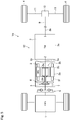
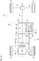
- a first embodiment of a powertrain of a hybrid vehicle (as will be simply called the “vehicle” hereinafter) Ve.
- the vehicle Ve comprises an engine (referred to as “ENG” in Fig. 1 ) 1, a motor (referred to as “MG” in Fig. 1 ) 2, a transmission (referred to as “TM” in Fig. 1 ) 3, drive wheels 4, a disconnecting clutch 5, and the pendulum damper 6.
- an internal combustion engine such as a gasoline engine and a diesel engine may be adopted as the engine 1.
- An output power of the engine 1 may be adjusted electrically, and the engine 1 may be started and stopped electrically according to need.
- an opening degree of a throttle valve, an amount of fuel supply, a commencement and a termination of ignition, an ignition timing etc. may be controlled electrically.
- an amount of fuel injection, an ignition timing, an opening degree of a throttle valve of an EGR system etc. may be controlled electrically.
- the motor 2 as a motor-generator is disposed on the output side of the engine 1.
- the motor 2 is driven as a motor to generate torque by supplying electricity thereto from a battery (not shown), and rotated as a generator by an output torque of the engine 1 to generate electricity.
- a permanent magnet type synchronous motor, and an induction motor may be adopted as the motor 2.
- a stator 2a and a rotor 2b are housed in a motor case 2c, and motor oil 7 is encapsulated in the motor case 2c.
- motor oil 7 is encapsulated in the motor case 2c.
- a bearing (not shown) supporting the rotor 2b and a coil end 2f are cooled and lubricated by the motor oil 7.
- the motor 2 is connected to the engine 1 in a power transmittable manner so that a cranking of the engine 1 may be performed by an output torque of the motor 2.
- the engine 1 is provided with a starter motor (not shown).
- the starter motor may be connected to the engine 1 through a speed reducing device (not shown) as a planetary gear unit comprising pinion gears and a ring gear.
- a spring damper 8 is disposed between the engine 1 and the motor 2.
- a conventional torsional damper installed in a flywheel may be adapted as the spring damper 8.
- the transmission 3 is disposed on a power transmission path 12 between the prime mover including the engine 1 and the motor 2 and the drive wheels 4 to transmit torque of the prime mover to the drive wheels 4.
- an automatic transmission such as a geared transmission and a continuously variable transmission, or a manual transmission may be used as the transmission 3.
- the transmission 3 is adapted to change a ratio of a speed of an input shaft 3a to a speed of an output shaft 3b arbitrarily.
- the transmission 3 is provided with a clutch that is engaged to transmit torque, and that is disengaged to interrupt torque transmission thereby establishing a neutral stage.
- the prime mover is connected to the drive wheels 4 through the transmission 3, a propeller shaft 9, a differential gear unit 10, and driveshafts 11 so that the output torque(s) of the prime mover is delivered to the drive wheels 4.
- the power transmission path 12 includes the engine 1, the motor 2, the transmission 3, the propeller shaft 9, the differential gear unit 10, the driveshafts 11, and the drive wheels 4.
- the vehicle Ve shown in Fig. 1 is a rear-drive layout vehicle in which a drive torque generated by the prime mover is delivered to a pair of rear wheels as drive wheels 4. Nonetheless, the present disclosure may also be applied to a front-drive layout vehicle in which the drive torque is delivered to a pair of front wheels, and a four-wheel-drive vehicle in which the drive torque is distributed to each pair of front wheels and rear wheels.
- the disconnecting clutch 5 selectively disconnects the engine 1 from the power transmission path 12. Specifically, the disconnecting clutch 5 is disposed on the power transmission path 12 to selectively interrupt a power transmission between the engine 1 and the pendulum damper 6. For example, the disconnecting clutch 5 is disengaged to interrupt a power transmission between the engine 1 and the pendulum damper 6 in cases of: (1) starting the engine 1; (2) stopping the engine 1; and (3) operating the engine 1 at a speed around an idling speed.
- a friction clutch that can be engaged while causing a slip may be adapted as the disconnecting clutch 5.
- a spring damper 8 is disposed downstream of the engine 1, and the disconnecting clutch 5 is disposed between the spring damper 8 and the motor 2. More specifically, a wet-type multiple-plate friction clutch is used as the disconnecting clutch 5, and the disconnecting clutch 5 is disposed in a motor case 2c between the spring damper 8 and the pendulum damper 6 disposed upstream of the motor 2.
- the vehicle Ve When the disconnecting clutch 5 is in engagement, the engine 1 is connected to the power transmission path 12.
- the vehicle Ve may be propelled in an engine mode by transmitting an output torque of the engine 1 to the drive wheels 4, or in a hybrid mode by transmitting output torques of the engine 1 and the motor 2 to the drive wheels 4.
- the disconnecting clutch 5 when the disconnecting clutch 5 is in disengagement, the engine 1 is disconnected from the power transmission path 12.
- the vehicle Ve may be propelled in an electric vehicle mode by transmitting an output torque of the motor 2 to the drive wheels 4.
- a drag loss of the engine 1 can be reduced thereby improving an energy efficiency.
- the disconnecting clutch 5 is disposed upstream of the pendulum damper 6 on the power transmission path 12.
- the disconnecting clutch 5 is disposed between the engine 1 and the pendulum damper 6. That is, when disengaging the disconnecting clutch 5, a power transmission between the engine 1 and the pendulum damper 6 is interrupted, and an inertial mass of the pendulum damper 6 is separated from a vibration system of the engine 1. For this reason, it is possible to prevent a reduction in a natural vibration frequency of the system including the engine 1 as might be caused by adding the inertial mass of the pendulum damper 6 to the system including the engine 1.
- the disconnecting clutch 5 may also be used as a fail-safe.
- the pendulum damper 6 disposed downstream of the disconnecting clutch 5 can be protected by disengaging the disconnecting clutch 5.
- the pendulum damper 6 can be prevented from being rotated excessively by disengaging the disconnecting clutch 5. For this reason, damage on the pendulum damper 6 can be limited.
- the pendulum damper 6 is adapted to absorb torsional vibrations on the power transmission path 12.
- the torsional vibration damper described in US 2012/0055283 A centrifugal pendulum dampers described in Japanese patent No. 5862767 and German Patent Publication No. 102014202138 may be adopted as the pendulum damper 6.
- an oscillating member itself serves as an inertial mass for establishing a vibration damping torque. According the embodiments of the present disclosure, however, other kinds of dampers may also be adopted as the pendulum damper 6.
- a pendulum damper in which a torque is applied to an inertial member through an oscillating member may also be adopted as the pendulum damper 6.
- the applicant of the present disclosure has proposed this kind of pendulum dampers in Japanese Patent Application Nos. 2016-26845 and 2017-153909 .
- a torque pulse suppressing device described in JP-A-2017-40318 may be categorized as this kind of pendulum damper. That is, the pendulum damper 6 is a dynamic damper that absorbs torsional vibrations on the power transmission path 12 resulting from torque pulse by an inertial force derived from an oscillating motion of a rolling member or a damper mass.
- the pendulum damper 6 is disposed downstream of the disconnecting clutch 5 on the power transmission path 12. In other words, the pendulum damper 6 is disposed on the power transmission path 12 between the disconnecting clutch 5 and the drive wheels 4. According to the first embodiment shown in Fig. 1 , the pendulum damper 6 is disposed in the motor case 2c between the disconnecting clutch 5 and the motor 2 while being connected to a rotor shaft 2d of the motor 2. Since the pendulum damper 6 is held in the motor case 2c, a dust cover for protecting pendulum damper 6 from dust and moisture the may be omitted.
- the motor oil 7 is encapsulated in the motor case 2c to lubricate the motor 2.
- the pendulum damper 6 may also be lubricated by the motor oil 7 held in the motor case 2c. That is, in the motor case 2c, not only the motor 2 but also the pendulum damper 6 can be lubricated by the motor oil 7.
- the pendulum damper 6 may be lubricated without requiring any specific lubrication device.
- the dry-type damper may also be arranged in the motor case 2c to serve as the pendulum damper 6 by covering the dry-type damper by a cover for blocking the motor oil 7 (not shown).
- number of oscillations of the oscillating member per revolution to suppress vibrations is set in accordance with a first vibration order of the engine 1 governed by number of cylinders and a combustion cycle. Otherwise, given that a permanent magnet type synchronous motor is used as the motor 2, in the pendulum damper 6, the number of oscillations of the oscillating member per revolution may also be set in accordance with a frequency of torque ripple or cogging torque per revolution governed by number of poles and a pitch angle of the poles of the motor 2. Further, in the pendulum damper 6, the number of oscillations of the oscillating member per revolution may also be set in accordance with a natural vibration frequency of an entire vibration system of the power transmission path 12.
- the torsional vibrations on the power transmission path 12 may be damped effectively by the pendulum damper 6.
- the number of oscillations of the oscillating member per revolution may be adjusted according to an outer diameter or dimensions of the pendulum damper 6, or according to a mass of the oscillating member or damper mass.
- the pendulum damper 6 is disposed closer to the drive wheels 4 than the disconnecting clutch 5. Therefore, the pendulum damper 6 can be disconnected from the system including the engine 1 by disengaging the disconnecting clutch 5 disposed between the system including the engine 1 and the pendulum damper 6. For this reason, it is possible to prevent a reduction in the natural vibration frequency of the system including the engine 1 as might be caused by adding the inertial mass of the pendulum damper 6 to the system including the engine 1.
- the natural vibration frequency of the system including the engine 1 may be raised to be higher than that at the idling speed by disengaging the disconnecting clutch 5 to disconnect the pendulum damper 6 from the system including the engine 1. According to the first embodiment, therefore, occurrence of resonance can be prevented when idling the engine 1, and when starting or stopping the engine 1. For this reason, N.V. performance of the vehicle Ve can be improved.
- FIG. 2 to 14 common reference numeral are allotted to the elements in common with those of the first embodiment shown in Fig. 1 .
- Fig. 2 there is shown the second embodiment of the present disclosure.
- the motor case 2c is joined to a transmission case 3c by e.g., a bolt to form a case 13, and the motor 2 and the transmission 3 are held in the case 13 while being connected to each other.
- both of the motor 2 and the transmission 3 may also be held in the motor case 2c or the transmission case 3c.
- Oil 14 for lubricating and cooling at least one of the motor 2 and the transmission 3 is held in the case 13.
- the aforementioned motor oil 7 used in the first embodiment may also serve as the oil 14.
- the disconnecting clutch 5 and the pendulum damper 6 are also arranged in the case 13, and the pendulum damper 6 is connected to the rotor shaft 2d of the motor 2.
- the pendulum damper 6 is arranged together with at least the motor 2, and lubricated by the oil 14.
- the pendulum damper 6 is connected to the rotor 2b of the motor 2.
- the pendulum damper 6 is connected to an output side of the disconnecting clutch 5.
- the pendulum damper 6 is connected to a rotor stay 2e of the motor 2.
- the pendulum damper 6 is connected to the rotor shaft 2d of the motor 2 as in the first and the second embodiments.
- the pendulum damper 6 is held in the motor case 2c on a front side of the motor 2, that is, an opening side of the motor case 2c. For this reason, the pendulum damper 6 may be fitted easily into the motor case 2c.
- the disconnecting clutch 5 is arranged in a hollow space 2g of the rotor 2b while being connected to the rotor shaft 2d.
- the disconnecting clutch 5 comprises an input member 5a connected to the output shaft 1a of the engine 1 through the spring damper 8, and an output member 5b connected to the rotor shaft 2d and the rotor 2b of the motor 2 in the hollow space 2g. Accordingly, the disconnecting clutch 5 is brought into engagement by engaging the input member 5a and the output member 5b with each other.
- the engine 1, the spring damper 8, the disconnecting clutch 5, the pendulum damper 6, the motor 2, and the transmission 3 are arranged in order on the power transmission path 12.
- the pendulum damper 6 is arranged in an inner circumferential space 2h of the coil end 2f of the motor 2.
- the coil end 2f is a portion of a coil wound around a core (not shown) of the stator 2a protruding in an axial direction respectively from each axial end of the stator 2a, and the pendulum damper 6 is held in the inner circumferential space 2h of the coil end 2f protruding toward the front side of the vehicle Ve.
- the axial length of the power transmission path 12 may also be reduced.
- the pendulum damper 6 is also connected to the rotor shaft 2d of the motor 2 as the first and the second embodiments.
- Fig. 8 there is shown the eighth embodiment of the present disclosure.
- the pendulum damper 6 is arranged in the motor case 2c on the rear side of the motor 2 while being connected to the rotor shaft 2d of the motor 2.
- the rotor shaft 2d is connected to the input shaft 3a of the transmission 3.
- the pendulum damper 6 is arranged in the available space of the rear section of the motor case 2c. According to the eighth embodiment shown in Fig. 8 , therefore, the axial length of the power transmission path 12 may also be reduced.
- a torque converter 21 is arranged on the power transmission path 12 between the output side of the motor 2 and the transmission 3. Specifically, an input shaft 21a of the torque converter 21 is connected to the rotor shaft 2d of the motor 2, and an output shaft 21b of the torque converter 21 is connected to the input shaft 3a of the transmission 3.
- the torque converter 21 comprises a lockup clutch 22 and a spring damper 23, and the lockup clutch 22 and the spring damper 23 are held in a case 21c of the torque converter 21.
- the vehicle Ve is provided with the spring damper 8 arranged on the output side of the engine 1 and the spring damper 23 arranged in the case 21c of the torque converter 21.
- the disconnecting clutch 5 is arranged in the motor case 2c on the front side of the motor 2.
- the disconnecting clutch 5 is disposed on the power transmission path 12 between the engine 1 and the motor 2.
- the pendulum damper 6 is arranged in the case 21c of the torque converter 21 while being connected to the output shaft 21b of the torque converter 21.
- the pendulum damper 6 is disposed on the power transmission path 12 between the torque converter 21 and the transmission 3.
- the pendulum damper 6 may be lubricated by an automatic transmission fluid (not shown) held in the case 21c of the torque converter 21.
- the pendulum damper 6 may be lubricated without requiring any specific lubrication device.
- two spring dampers 8 and 23 are arranged upstream of the pendulum damper 6. According to the ninth embodiment, therefore, stiffness of each of the spring dampers 8 and 23 may be reduced respectively so that the vibration damping performance of the pendulum damper 6 is enhanced.
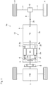
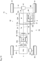
- a prime mover of the vehicle Ve includes the engine 1, a first motor (referred to as "MG1" in Fig. 10 ) 31, and a second motor (referred to as "MG2" in Fig. 10 ) 32.
- the vehicle Ve according to the tenth embodiment comprises the transmission 3, a pair of front wheels 33, a pair of rear wheels 34, and a transfer (referred to as "TF" in Fig. 10 ) 35.
- the first motor 31 as a motor-generator is also disposed on the output side of the engine 1.
- a permanent magnet type synchronous motor, and an induction motor may be adopted as the first motor 31.
- the disconnecting clutch 5 and the pendulum damper 6 are arranged in a motor case 31a of the first motor 31.
- the second motor 32 is also a motor-generator, and installed in the transfer 35.
- a permanent magnet type synchronous motor, and an induction motor may also be adopted as the second motor 32.
- a drive torque generated by the prime mover including the engine 1, the first motor 31, and the second motor 32 is delivered to both pairs of the front wheels 33 and the rear wheels 34 to establish a drive force to propel the vehicle Ve.
- the transfer 35 is a transmission mechanism adapted to switch a drive mode between two-wheel drive mode in which the drive torque is delivered to any one of the pairs of the front wheels 33 and the rear wheels 34, and four-wheel drive mode in which the drive torque is delivered to both pairs of the front wheels 33 and the rear wheels 34.
- the drive mode may be fixed to the four-wheel drive mode by the transfer 35 according to need.
- a differential gear mechanism and a chain-drive mechanism may be adopted as the transfer 35.
- the transfer 35 comprises an input shaft 35a connected to the output shaft 3b of the transmission 3, a front output shaft 35b connected to an after-mentioned front propeller shaft 37, a rear output shaft 35c connected to an after-mentioned rear propeller shaft 41, and a transfer case 35d holding the transfer 35 and the second motor 32.
- Transfer oil 36 for lubricating and cooling at least the transfer 35 and the second motor 32 is also held in the transfer case 35d.
- the second motor 32 is connected to the front output shaft 35b.
- the input shaft 35a and the rear output shaft 35c are connected to each other in a power transmittable manner, and the front output shaft 35b is interlinked with the input shaft 35a and the rear output shaft 35c through a geared transmission mechanism or a chain drive mechanism (neither of which are shown).
- a geared transmission mechanism or a chain drive mechanism (neither of which are shown).
- each of the front wheels 33 is connected individually to the engine 1 and the first motor 31 through the transmission 3, the transfer 35, the front propeller shaft 37, a front differential gear unit 38, and a front driveshaft 39.
- Each of the front wheels 33 is also connected individually to the second motor 32 through the front propeller shaft 37, the front differential gear unit 38, and the front driveshaft 39.
- a first power transmission path 40 is formed between the engine 1 and the pair of front wheels 33 thorough the first motor 31, the transfer 35, the front propeller shaft 37, the front differential gear unit 38, and the front driveshaft 39.
- each of the rear wheels 34 is connected individually to the engine 1 and the first motor 31 through the transmission 3, the transfer 35, a rear propeller shaft 41, a rear differential gear unit 42, and a rear driveshaft 43.
- Each of the rear wheels 34 is also connected individually to the second motor 32 through the transfer 35, the rear propeller shaft 41, the rear differential gear unit 42, and the rear driveshaft 43.
- a second power transmission path 44 is formed between the engine 1 and the pair of rear wheels 34 thorough the first motor 31, the transfer 35, the rear propeller shaft 41, the rear differential gear unit 42, and the rear driveshaft 43.
- the first power transmission path 40 is formed between the engine 1 and the pair of front wheels 33
- the second power transmission path 44 is formed between the engine 1 and the pair of rear wheels 34.
- the first motor 31 is disposed on the power transmission path closer to the drive wheels than the disconnecting clutch 5
- the second motor 32 is disposed on the power transmission path closer to the drive wheels than the first motor 31.
- the first motor 31 is situated closer to the front wheels 33 than the disconnecting clutch 5, and in the second power transmission path 44, the first motor 31 is situated closer to the rear wheels 34 than the disconnecting clutch 5.
- the second motor 32 is situated closer to the front wheels 33 than the first motor 31, and in the second power transmission path 44, the second motor 32 is situated closer to the rear wheels 34 than the first motor 31.
- the disconnecting clutch 5 is disposed between the engine 1 and the first motor 31, and in the second power transmission path 44, the disconnecting clutch 5 is disposed between the engine 1 and the second motor 32.
- the engine 1 can be disconnected from each of the first power transmission path 40 and the second power transmission path 44 by disengaging the disconnecting clutch 5.
- a drag loss as might be caused by rotating the engine 1 passively can be prevented by disengaging the disconnecting clutch 5 during propulsion in the electric vehicle mode in which the vehicle Ve is powered by the first motor 31 and the second motor 32. In other words, energy efficiency in the electric vehicle mode can be improved.
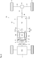
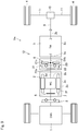
- the prime mover includes the engine 1 and a motor (referred to as "MG" in Fig. 11 ) 51.
- the vehicle Ve shown in Fig. 11 comprises the transmission 3, a disconnecting clutch 52, the pendulum damper 6, the front wheels 33, the rear wheels 34, and a transfer (referred to as "TF" in Fig. 11 ) 53.
- the motor 51 as a motor-generator is disposed on the output side of the engine 1.
- a permanent magnet type synchronous motor, and an induction motor may be adopted as the motor 51.
- the motor 51 is installed in the transfer 53.
- a clutch 3d of the transmission 3 serves as the disconnecting clutch 52.
- the clutch 3d When the clutch 3d is engaged, the transmission 3 is allowed to transmit torque therethrough with a predetermined speed ratio or in a predetermined gear stage.
- the clutch 3d When the clutch 3d is disengaged, the transmission 3 is brought into a neutral stage so that torque transmission through the transmission 3 is interrupted.
- the clutch 3d of the transmission 3 As the disconnecting clutch 52, number of parts can be reduced. For this reason, the vehicle Ve may be downsized and a weight of the vehicle Ve may be reduced. In addition, a manufacturing cost of the vehicle Ve may be reduced.
- the transfer 53 comprises an input shaft 53a connected to the output shaft 3b of the transmission 3, a front output shaft 53b connected to the front propeller shaft 37, a rear output shaft 53c connected to the rear propeller shaft 41, and a transfer case 53d holding the transfer 35 and the motor 51.
- Transfer oil 54 for lubricating and cooling at least the transfer 53, the motor 51, and the pendulum damper 6 is also held in the transfer case 53d.
- the motor 51 is connected to the front output shaft 53b.
- the input shaft 53a and the rear output shaft 53c are connected to each other in a power transmittable manner, and the front output shaft 53b is interlinked with the input shaft 53a and the rear output shaft 53c through a geared transmission mechanism or a chain drive mechanism (neither of which are shown).
- a geared transmission mechanism or a chain drive mechanism (neither of which are shown).
- the pendulum damper 6 is also held in the transfer 53 together with the motor 51. Specifically, the pendulum damper 6 is arranged in a front section of the transfer case 53d while being connected to the input shaft 53a of the transfer 53.
- each of the front wheels 33 is connected individually to the engine 1 and the motor 51 through the transmission 3, the transfer 53, the front propeller shaft 37, the front differential gear unit 38, and the front driveshaft 39.
- a first power transmission path 55 is formed between the engine 1 and the pair of front wheels 33 thorough the motor 51, the transfer 53, the front propeller shaft 37, the front differential gear unit 38, and the front driveshaft 39.
- each of the rear wheels 34 is connected individually to the engine 1 and the motor 51 through the transmission 3, the transfer 53, the rear propeller shaft 41, the rear differential gear unit 42, and the rear driveshaft 43.
- a second power transmission path 56 is formed between the engine 1 and the pair of rear wheels 34 thorough the motor 51, the transfer 53, the rear propeller shaft 41, the rear differential gear unit 42, and the rear driveshaft 43.
- the first power transmission path 55 is formed between the engine 1 and the pair of front wheels 33
- the second power transmission path 56 is formed between the engine 1 and the pair of rear wheels 34.
- the disconnecting clutch 52 is situated between the engine 1 and the motor 51 not only in the first power transmission path 55 but also in the second power transmission path 56.
- the engine 1 can be disconnected from each of the first power transmission path 55 and the second power transmission path 56 by disengaging the disconnecting clutch 52.
- a drag loss as might be caused by rotating the engine 1 passively can be prevented by disengaging the disconnecting clutch 52 during propulsion in the electric vehicle mode in which the vehicle Ve is powered by the motor 51. In other words, energy efficiency in the electric vehicle mode can be improved.
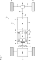
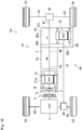
- the prime mover of the vehicle Ve includes the engine 1 and two motors.
- the prime mover includes the engine 1, a first motor (referred to as “MG1” in Fig. 12 ) 61, and a second motor (referred to as “MG2" in Fig. 12 ) 62.
- the vehicle Ve may be powered by both of the first motor 61 and the second motor 62 in the electric vehicle mode.
- the first motor 61 as a motor-generator is disposed on the output side of the engine 1.
- a permanent magnet type synchronous motor, and an induction motor may also be adopted as the first motor 61.
- the first motor 61 is also installed in the transfer 53.
- the second motor 62 as a motor-generator is also disposed on the output side of the engine 1 while being connected to the engine 1 through the spring damper 8.
- a permanent magnet type synchronous motor, and an induction motor may also be adopted as the second motor 62.
- the disconnecting clutch 52 and the pendulum damper may be arranged in a motor case 62a of the second motor 62.
- a first power transmission path 63 is formed between the engine 1 and the pair of front wheels 33 thorough the second motor 62, the transmission 3, the first motor 31, the transfer 53, the front propeller shaft 37, the front differential gear unit 38, and the front driveshaft 39.
- a second power transmission path 64 is formed between the engine 1 and the pair of rear wheels 34 thorough the second motor 62, the transmission 3, the first motor 31, the transfer 53, the rear propeller shaft 41, the rear differential gear unit 42, and the rear driveshaft 43.
- the first power transmission path 63 is formed between the engine 1 and the pair of front wheels 33
- the second power transmission path 64 is formed between the engine 1 and the pair of rear wheels 34.
- the first motor 61 is disposed on the power transmission path closer to the drive wheels than the disconnecting clutch 52
- the second motor 62 is disposed on the power transmission path closer to the drive wheels than the disconnecting clutch 52.
- the first motor 61 is situated closer to the front wheels 33 than the disconnecting clutch 52 (or the clutch 3d), and in the second power transmission path 64, the first motor 61 is situated closer to the rear wheels 34 than the disconnecting clutch 52 (or the clutch 3d).
- the second motor 62 is situated closer to the engine 1 than the disconnecting clutch 52 (or the clutch 3d)
- the second motor 62 is situated closer to the engine 1 than the disconnecting clutch 52 (or the clutch 3d).
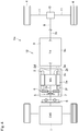
- the pendulum damper 6 is held in the transfer case 53d on the opening side of the transfer case 53d while being connected to the input shaft 53a. For this reason, the pendulum damper 6 may be fitted easily into the transfer case 53d.
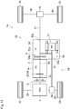
- the pendulum damper 6 may also be arranged in the transfer case 53d on the output side of the motor 51, that is, on the opening side of the transfer case 53d while being connected to the front output shaft 53b or the motor 51. Further, according to the fourteenth embodiment shown in Fig. 14 , the pendulum damper 6 may also be arranged in the transfer case 53d on the output side of the first motor 61, that is, on the opening side of the transfer case 53d while being connected to the front output shaft 53b or the first motor 61.
- the pendulum damper 6 is held in the transfer case 53d on the opening side of the transfer case 53d in the thirteenth and the fourteenth embodiments. For this reason, the pendulum damper 6 may also be fitted easily into the transfer case 53d.
- the pendulum damper 6 is arranged coaxially with the motor 51 or the first motor 61.
- Each of the motor 51 and the first motor 61 serves individually as a prime mover of the vehicle Ve.
- a motor having a relatively large outer diameter is used as the motor 51 and the first motor 61 respectively so as to generate large drive torque.
- an outer diameter of the motor 51 is larger than an outer diameter of the transmission 3 at a portion connected to the transfer 53. For this reason, dimensions of a lower upper portion of the transfer case 53d in Fig. 13 holding the motor 51 therein is larger than that of an upper portion of the transfer case 53d in Fig. 13 connected to the transmission 3.
- an outer diameter of the first motor 61 is larger than the outer diameter of the transmission 3 at the portion connected to the transfer 53. For this reason, dimensions of the lower upper portion of the transfer case 53d in Fig. 14 holding the first motor 61 therein is larger than that of the upper portion of the transfer case 53d in Fig. 14 connected to the transmission 3. According to the thirteenth and the fourteenth embodiments, therefore, an outer diameter of the pendulum damper 6 may be increased in comparison with that of a case in which the pendulum damper 6 is arranged on the side connected to the transmission 3. That is, design flexibility of the pendulum damper 6 may be increased. For this reason, vibration damping performance of the pendulum damper 6 may be increased.
Landscapes
- Engineering & Computer Science (AREA)
- Mechanical Engineering (AREA)
- Transportation (AREA)
- Chemical & Material Sciences (AREA)
- Combustion & Propulsion (AREA)
- General Engineering & Computer Science (AREA)
- Power Engineering (AREA)
- Acoustics & Sound (AREA)
- Aviation & Aerospace Engineering (AREA)
- Physics & Mathematics (AREA)
- Automation & Control Theory (AREA)
- Hybrid Electric Vehicles (AREA)
- Electric Propulsion And Braking For Vehicles (AREA)
- Arrangement Of Transmissions (AREA)
- Connection Of Motors, Electrical Generators, Mechanical Devices, And The Like (AREA)
- Motor Or Generator Cooling System (AREA)
- Arrangement And Driving Of Transmission Devices (AREA)
Description
- The present disclosure claims the benefit of Japanese Patent Application No.
2017-170356 filed on September 5, 2017 - Embodiments of the present disclosure relate to the art of a hybrid vehicle in which a prime mover includes an engine and a motor. More specifically, the embodiments of the present disclosure relate to hybrid vehicle comprising a clutch for selectively disconnecting an engine from a power transmission path, and a pendulum damper for suppressing torsional vibration on the power transmission path.
-
WO 2016/070878 A1 discloses "a hybrid module for a motor vehicle power train, comprising an input side for connecting to an internal combustion engine, an output side for connecting to a drive wheel, an electric drive motor comprising a stator and a rotor and a torque transfer device is arranged between the rotor and the output side. Said transfer device is designed to reduce rotational irregularity". -
WO 2008/025691 A1 discloses "a hybrid drive unit for a motor vehicle for installation between an internal combustion engine and a vehicle transmission, which hybrid drive unit has an electric machine with a rotor and a stator and can be operated as a motor or a generator. Arranged radially within the electric machine is at least one switchable clutch, and the vehicle transmission has a transmission input shaft and a transmission housing. Coolant, for example cooling oil, is supplied to and discharged from the transmission to the hybrid drive unit substantially for the purpose of cooling the clutch, by means of a central coolant supply. Connected to the central coolant supply is a substantially closed coolant circuit in which is provided, in a region of the clutch, a pressure compensating space which can be traversed by the coolant of the coolant circuit". -
US 2012/0055283 A describes a hybrid vehicle comprising a torsional vibration damper. In the hybrid vehicle taught byUS 2012/0055283 A , a motor is disposed on an output side of an engine, and a transmission is disposed on an output side of the motor. A clutch is disposed between the engine and the motor to selectively provide a connection therebetween. A first spring damping system is arranged between the engine and the clutch, and a second spring damping system is arranged between the motor and the transmission. The first spring damping system serves as the torsional vibration damper together with a centrifugal pendulum to absorb vibration of a power transmission path by an oscillating motion of the centrifugal pendulum. - In the hybrid vehicle taught by
US 2012/0055283 , specifically, the torsional vibration damper is arranged closer to the engine than the clutch. That is, in the power transmission path between the engine and the clutch, the spring damping system and the centrifugal pendulum are connected to the engine. Consequently, a natural vibration frequency is reduced by an inertial mass of the centrifugal pendulum. If the natural vibration frequency is reduced close to a vibration frequency of the engine at an idling speed, a resonance may occur during operation of the engine at the idling speed, or when starting or stopping the engine. For this reason, N.V. performance of the vehicle may be reduced. - Aspects of embodiments of the present disclosure have been conceived noting the foregoing technical problems, and it is therefore an object of the present disclosure to improve N.V. performance of a hybrid vehicle having a pendulum damper, by avoiding a resonance at around an idling speed of an engine, and by suppressing vibrations on a power transmission path.
- In the hybrid vehicle according to at least one embodiment of the present invention, a prime mover includes an engine and at least one motor. The hybrid vehicle comprises: a drive wheel; a power transmission path from the engine to the drive wheel via the motor; a pendulum damper that is arranged on the power transmission path to absorb torsional vibrations on the power transmission path; and a disconnecting clutch that is arranged on the power transmission path to selectively interrupt power transmission between the engine and the pendulum damper.
- The disconnecting clutch is disposed between the engine and the motor, and the pendulum damper is disposed closer to the drive wheel than the disconnecting clutch.
- The motor includes a motor case holding a motor oil for lubricating at least the motor. The pendulum damper is arranged in the motor case together with at least the motor and the pendulum damper is lubricated by the motor oil.
- In a non-limiting embodiment, the motor may include a coil end as a portion of a coil protruding in an axial direction from an axial end of a stator of the motor, and the pendulum damper may be held in an inner circumferential space of the coil end.
- In a non-limiting embodiment, the disconnecting clutch may be arranged in the motor case together with at least the motor.
- In a non-limiting embodiment, the motor may include a rotor, and the disconnecting clutch may be arranged in a hollow space of the rotor.
- In a non-limiting embodiment, the hybrid vehicle may comprise a transmission that is arranged on the power transmission path to transmit torque to the drive wheel with a predetermined speed ratio, and that is selectively brought into neutral stage. The transmission may include a clutch that is selectively engaged and disengaged to establish the predetermined speed ratio and the neutral stage, and the transmission may serve as the disconnecting clutch.
- In a non-limiting embodiment, the drive wheel may include a pair of front wheels and a pair of rear wheels. The hybrid vehicle may further comprise a transfer that is disposed on the power transmission path. The transfer may be adapted to switch a drive mode between two-wheel drive mode in which a drive torque is delivered to any one of the pairs of the front wheels and the rear wheels, and four-wheel drive mode in which a drive torque is delivered to both pairs of the front wheels and the rear wheels. Instead, the drive mode may be fixed to the four-wheel drive mode. In addition, the power transmission path may include a first power transmission path from the engine to the front wheels via the transfer, and a second power transmission path from the engine to the rear wheels via the transfer.
- The transfer includes a transfer case holding a transfer oil for lubricating and cooling at least the transfer, and the motor is held in the transfer case together with at least the transfer.
- The pendulum damper is held in the transfer case together with at least the transfer and the motor, and the pendulum damper is lubricated by the transfer oil.
- In a non-limiting embodiment, number of oscillations of an oscillating member of the pendulum damper per revolution may be set in accordance with a first vibration order of the engine governed by a combustion cycle in the engine.
- In a non-limiting embodiment, number of oscillations of an oscillating member of the pendulum damper per revolution may be set in accordance with a first vibration order of the motor governed by a number of poles of the motor.
- Thus, according to the embodiments of the present disclosure, the pendulum damper for suppressing torsional vibrations on the power transmission path, and the disconnecting clutch for selectively interrupting power transmission between the engine and the pendulum damper are disposed on the power transmission path. Specifically, the pendulum damper is arranged on the power transmission path closer to the drive wheels than the disconnecting clutch. In other words, the pendulum damper is arranged on an opposite side to the engine across the disconnecting clutch. According to the embodiments of the present disclosure, therefore, the engine may be disconnected from the power transmission path, and the inertial mass of the pendulum damper may be disconnected from a system including the engine, by disengaging the disconnecting clutch. Consequently, a natural vibration frequency of the system including the engine is raised. That is, reduction in the natural vibration frequency of the system including the engine to an idling speed of the engine can be prevented. For this reason, occurrence of resonance in the system including the engine can be prevented when operating the engine at around the idling speed, or when starting or stopping the engine.
- In addition, according to the embodiments of the present disclosure, the pendulum damper is arranged downstream of the disconnecting clutch, in other words, between the disconnecting clutch and the drive wheel. According to the embodiments of the present disclosure, therefore, torsional vibrations on the power transmission path may be damped even if the engine is disconnected from the power transmission path by disengaging the disconnecting clutch. For example, torsional vibrations generated by factors other than engine such as torque ripple and cogging torque of a permanent magnet type synchronous motor may be suppressed by the pendulum damper. Thus, according to the embodiments of the present disclosure, it is possible to reduce noises and vibrations on the power transmission path by avoiding occurrence of resonance at around the idling speed of the engine. For this reason, N.V. performance of the vehicle can be improved.
- Features, aspects, and advantages of exemplary embodiments of the present invention will become better understood with reference to the following description and accompanying drawings, which should not limit the invention in any way.
-
Fig. 1 is a schematic illustration showing a first embodiment of the hybrid vehicle according to the present disclosure; -
Fig. 2 is a schematic illustration showing a second embodiment of the hybrid vehicle according to the present disclosure; -
Fig. 3 is a schematic illustration showing a third embodiment of the hybrid vehicle according to the present disclosure; -
Fig. 4 is a schematic illustration showing a fourth embodiment of the hybrid vehicle according to the present disclosure; -
Fig. 5 is a schematic illustration showing a fifth embodiment of the hybrid vehicle according to the present disclosure; -
Fig. 6 is a schematic illustration showing a sixth embodiment of the hybrid vehicle according to the present disclosure; -
Fig. 7 is a schematic illustration showing a seventh embodiment of the hybrid vehicle according to the present disclosure; -
Fig. 8 is a schematic illustration showing an eighth embodiment of the hybrid vehicle according to the present disclosure; -
Fig. 9 is a schematic illustration showing a ninth embodiment of the hybrid vehicle according to the present disclosure; -
Fig. 10 is a schematic illustration showing a tenth embodiment of the hybrid vehicle according to the present disclosure; -
Fig. 11 is a schematic illustration showing an eleventh embodiment of the hybrid vehicle according to the present disclosure; -
Fig. 12 is a schematic illustration showing a twelfth embodiment of the hybrid vehicle according to the present disclosure; -
Fig. 13 is a schematic illustration showing a thirteenth embodiment of the hybrid vehicle according to the present disclosure; and -
Fig. 14 is a schematic illustration showing a fourteenth embodiment of the hybrid vehicle according to the present disclosure. - Preferred embodiments of the present disclosure will now be explained with reference to the accompanying drawings.
- The present disclosure is applied to a hybrid vehicle having an engine and at least one motor. In the hybrid vehicle, the motor is disposed on an output side of the engine to deliver torque to drive wheels via a transmission. The hybrid vehicle is provided with a disconnecting clutch that selectively disconnects the engine from a power transmission path between the engine and drive wheels, and a pendulum damper that damps torsional vibrations on the power transmission path.
- Referring now to
Fig. 1 , there is schematically shown a first embodiment of a powertrain of a hybrid vehicle (as will be simply called the "vehicle" hereinafter) Ve. The vehicle Ve comprises an engine (referred to as "ENG" inFig. 1 ) 1, a motor (referred to as "MG" inFig. 1 ) 2, a transmission (referred to as "TM" inFig. 1 ) 3,drive wheels 4, a disconnectingclutch 5, and thependulum damper 6. - For example, an internal combustion engine such as a gasoline engine and a diesel engine may be adopted as the
engine 1. An output power of theengine 1 may be adjusted electrically, and theengine 1 may be started and stopped electrically according to need. For example, given that the gasoline engine is used as theengine 1, an opening degree of a throttle valve, an amount of fuel supply, a commencement and a termination of ignition, an ignition timing etc. may be controlled electrically. Otherwise, given that the diesel engine is used as theengine 1, an amount of fuel injection, an ignition timing, an opening degree of a throttle valve of an EGR system etc. may be controlled electrically. - The
motor 2 as a motor-generator is disposed on the output side of theengine 1. Themotor 2 is driven as a motor to generate torque by supplying electricity thereto from a battery (not shown), and rotated as a generator by an output torque of theengine 1 to generate electricity. For example, a permanent magnet type synchronous motor, and an induction motor may be adopted as themotor 2. - In the
motor 2, astator 2a and arotor 2b are housed in amotor case 2c, andmotor oil 7 is encapsulated in themotor case 2c. Specifically, a bearing (not shown) supporting therotor 2b and acoil end 2f are cooled and lubricated by themotor oil 7. - The
motor 2 is connected to theengine 1 in a power transmittable manner so that a cranking of theengine 1 may be performed by an output torque of themotor 2. In order to start theengine 1 when a temperature of theengine 1 is low, or after parking the vehicle Ve for a long time, theengine 1 is provided with a starter motor (not shown). For example, the starter motor may be connected to theengine 1 through a speed reducing device (not shown) as a planetary gear unit comprising pinion gears and a ring gear. - In order to absorb torsional vibrations resulting from pulsation of an output torque of the
engine 1, according to the first embodiment shown inFig. 1 , aspring damper 8 is disposed between theengine 1 and themotor 2. For example, a conventional torsional damper installed in a flywheel may be adapted as thespring damper 8. - The
transmission 3 is disposed on apower transmission path 12 between the prime mover including theengine 1 and themotor 2 and thedrive wheels 4 to transmit torque of the prime mover to thedrive wheels 4. For example, an automatic transmission such as a geared transmission and a continuously variable transmission, or a manual transmission may be used as thetransmission 3. Thetransmission 3 is adapted to change a ratio of a speed of aninput shaft 3a to a speed of anoutput shaft 3b arbitrarily. Preferably, thetransmission 3 is provided with a clutch that is engaged to transmit torque, and that is disengaged to interrupt torque transmission thereby establishing a neutral stage. - The prime mover is connected to the
drive wheels 4 through thetransmission 3, apropeller shaft 9, adifferential gear unit 10, anddriveshafts 11 so that the output torque(s) of the prime mover is delivered to thedrive wheels 4. Thus, according to the first embodiment shown inFig. 1 , thepower transmission path 12 includes theengine 1, themotor 2, thetransmission 3, thepropeller shaft 9, thedifferential gear unit 10, thedriveshafts 11, and thedrive wheels 4. - Thus, the vehicle Ve shown in
Fig. 1 is a rear-drive layout vehicle in which a drive torque generated by the prime mover is delivered to a pair of rear wheels asdrive wheels 4. Nonetheless, the present disclosure may also be applied to a front-drive layout vehicle in which the drive torque is delivered to a pair of front wheels, and a four-wheel-drive vehicle in which the drive torque is distributed to each pair of front wheels and rear wheels. - The disconnecting clutch 5 selectively disconnects the
engine 1 from thepower transmission path 12. Specifically, the disconnectingclutch 5 is disposed on thepower transmission path 12 to selectively interrupt a power transmission between theengine 1 and thependulum damper 6. For example, the disconnectingclutch 5 is disengaged to interrupt a power transmission between theengine 1 and thependulum damper 6 in cases of: (1) starting theengine 1; (2) stopping theengine 1; and (3) operating theengine 1 at a speed around an idling speed. - For example, a friction clutch that can be engaged while causing a slip may be adapted as the disconnecting
clutch 5. According to the first embodiment shown inFig. 1 , aspring damper 8 is disposed downstream of theengine 1, and the disconnectingclutch 5 is disposed between thespring damper 8 and themotor 2. More specifically, a wet-type multiple-plate friction clutch is used as the disconnectingclutch 5, and the disconnectingclutch 5 is disposed in amotor case 2c between thespring damper 8 and thependulum damper 6 disposed upstream of themotor 2. - When the disconnecting
clutch 5 is in engagement, theengine 1 is connected to thepower transmission path 12. In this case, the vehicle Ve may be propelled in an engine mode by transmitting an output torque of theengine 1 to thedrive wheels 4, or in a hybrid mode by transmitting output torques of theengine 1 and themotor 2 to thedrive wheels 4. - By contrast, when the disconnecting
clutch 5 is in disengagement, theengine 1 is disconnected from thepower transmission path 12. In this case, the vehicle Ve may be propelled in an electric vehicle mode by transmitting an output torque of themotor 2 to thedrive wheels 4. In the electric vehicle mode, since theengine 1 is disconnected from thepower transmission path 12, a drag loss of theengine 1 can be reduced thereby improving an energy efficiency. - As described, the disconnecting
clutch 5 is disposed upstream of thependulum damper 6 on thepower transmission path 12. In other words, the disconnectingclutch 5 is disposed between theengine 1 and thependulum damper 6. That is, when disengaging the disconnectingclutch 5, a power transmission between theengine 1 and thependulum damper 6 is interrupted, and an inertial mass of thependulum damper 6 is separated from a vibration system of theengine 1. For this reason, it is possible to prevent a reduction in a natural vibration frequency of the system including theengine 1 as might be caused by adding the inertial mass of thependulum damper 6 to the system including theengine 1. In addition, the disconnectingclutch 5 may also be used as a fail-safe. For example, when theengine 1 is in trouble, thependulum damper 6 disposed downstream of the disconnecting clutch 5 can be protected by disengaging the disconnectingclutch 5. Specifically, when a speed of theengine 1 is raised excessively, thependulum damper 6 can be prevented from being rotated excessively by disengaging the disconnectingclutch 5. For this reason, damage on thependulum damper 6 can be limited. - The
pendulum damper 6 is adapted to absorb torsional vibrations on thepower transmission path 12. For example, the torsional vibration damper described inUS 2012/0055283 A , centrifugal pendulum dampers described in Japanese patent No.5862767 102014202138 may be adopted as thependulum damper 6. In any of those conventional dampers described in the above-listed prior art documents, an oscillating member itself serves as an inertial mass for establishing a vibration damping torque. According the embodiments of the present disclosure, however, other kinds of dampers may also be adopted as thependulum damper 6. For example, a pendulum damper in which a torque is applied to an inertial member through an oscillating member may also be adopted as thependulum damper 6. The applicant of the present disclosure has proposed this kind of pendulum dampers in Japanese Patent Application Nos.2016-26845 2017-153909 JP-A-2017-40318 pendulum damper 6 is a dynamic damper that absorbs torsional vibrations on thepower transmission path 12 resulting from torque pulse by an inertial force derived from an oscillating motion of a rolling member or a damper mass. - The
pendulum damper 6 is disposed downstream of the disconnectingclutch 5 on thepower transmission path 12. In other words, thependulum damper 6 is disposed on thepower transmission path 12 between the disconnectingclutch 5 and thedrive wheels 4. According to the first embodiment shown inFig. 1 , thependulum damper 6 is disposed in themotor case 2c between the disconnectingclutch 5 and themotor 2 while being connected to arotor shaft 2d of themotor 2. Since thependulum damper 6 is held in themotor case 2c, a dust cover for protectingpendulum damper 6 from dust and moisture the may be omitted. - As described, the
motor oil 7 is encapsulated in themotor case 2c to lubricate themotor 2. According to the embodiments of the present disclosure, not only a dry-type damper that is not necessary to be lubricated but also a wet-type damper that is necessary to be lubricated may be adopted as thependulum damper 6. Given that the wet-type damper is used as thependulum damper 6, thependulum damper 6 may also be lubricated by themotor oil 7 held in themotor case 2c. That is, in themotor case 2c, not only themotor 2 but also thependulum damper 6 can be lubricated by themotor oil 7. Thus, thependulum damper 6 may be lubricated without requiring any specific lubrication device. - In addition, by thus using the wet-type damper as the
pendulum damper 6, collision noise of the rolling member (or oscillating member) may be reduced by viscosity of themotor oil 7 when thependulum damper 6 starts rotating or when thependulum damper 6 stops. Otherwise, the dry-type damper may also be arranged in themotor case 2c to serve as thependulum damper 6 by covering the dry-type damper by a cover for blocking the motor oil 7 (not shown). - In the
pendulum damper 6, number of oscillations of the oscillating member per revolution to suppress vibrations is set in accordance with a first vibration order of theengine 1 governed by number of cylinders and a combustion cycle. Otherwise, given that a permanent magnet type synchronous motor is used as themotor 2, in thependulum damper 6, the number of oscillations of the oscillating member per revolution may also be set in accordance with a frequency of torque ripple or cogging torque per revolution governed by number of poles and a pitch angle of the poles of themotor 2. Further, in thependulum damper 6, the number of oscillations of the oscillating member per revolution may also be set in accordance with a natural vibration frequency of an entire vibration system of thepower transmission path 12. According to the embodiments of the present disclosure, therefore, the torsional vibrations on thepower transmission path 12 may be damped effectively by thependulum damper 6. In thependulum damper 6, the number of oscillations of the oscillating member per revolution may be adjusted according to an outer diameter or dimensions of thependulum damper 6, or according to a mass of the oscillating member or damper mass. - As described, if the natural vibration frequency of the system including the
engine 1 is reduced to the vibration frequency of theengine 1 at the idling speed, a resonance may occur in the system including theengine 1 when idling theengine 1, and when starting or stopping theengine 1. In order to avoid occurrence of such resonance, according to the first embodiment, thependulum damper 6 is disposed closer to thedrive wheels 4 than the disconnectingclutch 5. Therefore, thependulum damper 6 can be disconnected from the system including theengine 1 by disengaging the disconnecting clutch 5 disposed between the system including theengine 1 and thependulum damper 6. For this reason, it is possible to prevent a reduction in the natural vibration frequency of the system including theengine 1 as might be caused by adding the inertial mass of thependulum damper 6 to the system including theengine 1. - Given that a high-power engine having a supercharger is employed as the
engine 1, it is necessary to increase stiffness of thespring damper 8. However, if number of cylinders of theengine 1 is relatively small, e.g., three cylinders or four cylinders, a resonance point between thespring damper 8 and theengine 1 would be raised to around 1000rpm by increasing the stiffness of thespring damper 8. Consequently, the natural vibration frequency of the system including theengine 1 would be reduced to the vibration frequency of theengine 1 at around the idling speed. However, according to the first embodiment, the natural vibration frequency of the system including theengine 1 may be raised to be higher than that at the idling speed by disengaging the disconnecting clutch 5 to disconnect thependulum damper 6 from the system including theengine 1. According to the first embodiment, therefore, occurrence of resonance can be prevented when idling theengine 1, and when starting or stopping theengine 1. For this reason, N.V. performance of the vehicle Ve can be improved. - Next, here will be explained another embodiments of the present disclosure with reference to
Figs. 2 to 14 . InFigs. 2 to 14 common reference numeral are allotted to the elements in common with those of the first embodiment shown inFig. 1 . - Turning to
Fig. 2 , there is shown the second embodiment of the present disclosure. According to the second embodiment, themotor case 2c is joined to atransmission case 3c by e.g., a bolt to form acase 13, and themotor 2 and thetransmission 3 are held in thecase 13 while being connected to each other. Instead, both of themotor 2 and thetransmission 3 may also be held in themotor case 2c or thetransmission case 3c. -
Oil 14 for lubricating and cooling at least one of themotor 2 and thetransmission 3 is held in thecase 13. Theaforementioned motor oil 7 used in the first embodiment may also serve as theoil 14. The disconnectingclutch 5 and thependulum damper 6 are also arranged in thecase 13, and thependulum damper 6 is connected to therotor shaft 2d of themotor 2. According to the second embodiment, thependulum damper 6 is arranged together with at least themotor 2, and lubricated by theoil 14. - According to the third embodiment shown in
Fig. 3 , thependulum damper 6 is connected to therotor 2b of themotor 2. According to the fourth embodiment shown inFig. 4 , thependulum damper 6 is connected to an output side of the disconnectingclutch 5. According to the fifth and sixth embodiments shown inFigs. 5 and6 , thependulum damper 6 is connected to arotor stay 2e of themotor 2. According to the seventh embodiment shown inFig. 7 , thependulum damper 6 is connected to therotor shaft 2d of themotor 2 as in the first and the second embodiments. - In any of the first and the third to seventh embodiments, the
pendulum damper 6 is held in themotor case 2c on a front side of themotor 2, that is, an opening side of themotor case 2c. For this reason, thependulum damper 6 may be fitted easily into themotor case 2c. - According to the sixth embodiment shown in
Fig. 6 , the disconnectingclutch 5 is arranged in ahollow space 2g of therotor 2b while being connected to therotor shaft 2d. The disconnectingclutch 5 comprises aninput member 5a connected to theoutput shaft 1a of theengine 1 through thespring damper 8, and anoutput member 5b connected to therotor shaft 2d and therotor 2b of themotor 2 in thehollow space 2g. Accordingly, the disconnectingclutch 5 is brought into engagement by engaging theinput member 5a and theoutput member 5b with each other. Thus, according to the sixth embodiment, theengine 1, thespring damper 8, the disconnectingclutch 5, thependulum damper 6, themotor 2, and thetransmission 3 are arranged in order on thepower transmission path 12. By thus arranging the disconnecting clutch 5 in thehollow space 2g of therotor 2b, an axial length of thepower transmission path 12 may be reduced. - According to the seventh embodiment shown in
Fig. 7 , thependulum damper 6 is arranged in an innercircumferential space 2h of thecoil end 2f of themotor 2. Specifically, thecoil end 2f is a portion of a coil wound around a core (not shown) of thestator 2a protruding in an axial direction respectively from each axial end of thestator 2a, and thependulum damper 6 is held in the innercircumferential space 2h of thecoil end 2f protruding toward the front side of the vehicle Ve. According to the seventh embodiment shown inFig. 7 , therefore, the axial length of thepower transmission path 12 may also be reduced. - According to the seventh embodiment shown in
Fig. 7 , thependulum damper 6 is also connected to therotor shaft 2d of themotor 2 as the first and the second embodiments. - Turning to
Fig. 8 , there is shown the eighth embodiment of the present disclosure. According to the eighth embodiment, thependulum damper 6 is arranged in themotor case 2c on the rear side of themotor 2 while being connected to therotor shaft 2d of themotor 2. Therotor shaft 2d is connected to theinput shaft 3a of thetransmission 3. - In general, electric wires of the
motor 2 and oil pipes for circulating themotor oil 7 are concentrated to the front section of themotor case 2c, and hence an available space in the rear section of themotor case 2c is relatively large. In the eighth embodiment, thependulum damper 6 is arranged in the available space of the rear section of themotor case 2c. According to the eighth embodiment shown inFig. 8 , therefore, the axial length of thepower transmission path 12 may also be reduced. - Turning to
Fig. 9 , there is shown the ninth embodiment of the present disclosure. According to the ninth embodiment, atorque converter 21 is arranged on thepower transmission path 12 between the output side of themotor 2 and thetransmission 3. Specifically, aninput shaft 21a of thetorque converter 21 is connected to therotor shaft 2d of themotor 2, and anoutput shaft 21b of thetorque converter 21 is connected to theinput shaft 3a of thetransmission 3. Thetorque converter 21 comprises alockup clutch 22 and aspring damper 23, and thelockup clutch 22 and thespring damper 23 are held in acase 21c of thetorque converter 21. Thus, according to the ninth embodiment, the vehicle Ve is provided with thespring damper 8 arranged on the output side of theengine 1 and thespring damper 23 arranged in thecase 21c of thetorque converter 21. - According to the ninth embodiment, the disconnecting
clutch 5 is arranged in themotor case 2c on the front side of themotor 2. Thus, according to the embodiments of the present disclosure, the disconnectingclutch 5 is disposed on thepower transmission path 12 between theengine 1 and themotor 2. - According to the ninth embodiment, the
pendulum damper 6 is arranged in thecase 21c of thetorque converter 21 while being connected to theoutput shaft 21b of thetorque converter 21. Thus, thependulum damper 6 is disposed on thepower transmission path 12 between thetorque converter 21 and thetransmission 3. - Given that the wet-type damper is used as the
pendulum damper 6, thependulum damper 6 may be lubricated by an automatic transmission fluid (not shown) held in thecase 21c of thetorque converter 21. Thus, thependulum damper 6 may be lubricated without requiring any specific lubrication device. - Thus, according to the ninth embodiment, two
spring dampers pendulum damper 6. According to the ninth embodiment, therefore, stiffness of each of thespring dampers pendulum damper 6 is enhanced. - The present disclosure may also be applied to a four-wheel-drive vehicles as shown in
Figs. 10 to 14 . Turning toFig. 10 , there is shown the tenth embodiment of the present disclosure. According to the tenth embodiment, a prime mover of the vehicle Ve includes theengine 1, a first motor (referred to as "MG1" inFig. 10 ) 31, and a second motor (referred to as "MG2" inFig. 10 ) 32. The vehicle Ve according to the tenth embodiment comprises thetransmission 3, a pair offront wheels 33, a pair ofrear wheels 34, and a transfer (referred to as "TF" inFig. 10 ) 35. - The
first motor 31 as a motor-generator is also disposed on the output side of theengine 1. As described, a permanent magnet type synchronous motor, and an induction motor may be adopted as thefirst motor 31. According to the tenth embodiment, the disconnectingclutch 5 and thependulum damper 6 are arranged in amotor case 31a of thefirst motor 31. - The
second motor 32 is also a motor-generator, and installed in thetransfer 35. For example, a permanent magnet type synchronous motor, and an induction motor may also be adopted as thesecond motor 32. - In the vehicle Ve according to the tenth embodiment, a drive torque generated by the prime mover including the
engine 1, thefirst motor 31, and thesecond motor 32 is delivered to both pairs of thefront wheels 33 and therear wheels 34 to establish a drive force to propel the vehicle Ve. - The
transfer 35 is a transmission mechanism adapted to switch a drive mode between two-wheel drive mode in which the drive torque is delivered to any one of the pairs of thefront wheels 33 and therear wheels 34, and four-wheel drive mode in which the drive torque is delivered to both pairs of thefront wheels 33 and therear wheels 34. The drive mode may be fixed to the four-wheel drive mode by thetransfer 35 according to need. For example, a differential gear mechanism and a chain-drive mechanism may be adopted as thetransfer 35. - The
transfer 35 comprises aninput shaft 35a connected to theoutput shaft 3b of thetransmission 3, afront output shaft 35b connected to an after-mentionedfront propeller shaft 37, arear output shaft 35c connected to an after-mentionedrear propeller shaft 41, and atransfer case 35d holding thetransfer 35 and thesecond motor 32.Transfer oil 36 for lubricating and cooling at least thetransfer 35 and thesecond motor 32 is also held in thetransfer case 35d. Thesecond motor 32 is connected to thefront output shaft 35b. Theinput shaft 35a and therear output shaft 35c are connected to each other in a power transmittable manner, and thefront output shaft 35b is interlinked with theinput shaft 35a and therear output shaft 35c through a geared transmission mechanism or a chain drive mechanism (neither of which are shown). Thus, an output torque of thesecond motor 32 is delivered to at least one of the pairs of thefront wheels 33 and therear wheels 34 through thetransfer 35. - According to the tenth embodiment, each of the
front wheels 33 is connected individually to theengine 1 and thefirst motor 31 through thetransmission 3, thetransfer 35, thefront propeller shaft 37, a frontdifferential gear unit 38, and afront driveshaft 39. Each of thefront wheels 33 is also connected individually to thesecond motor 32 through thefront propeller shaft 37, the frontdifferential gear unit 38, and thefront driveshaft 39. In the vehicle Ve shown inFig. 10 , accordingly, a firstpower transmission path 40 is formed between theengine 1 and the pair offront wheels 33 thorough thefirst motor 31, thetransfer 35, thefront propeller shaft 37, the frontdifferential gear unit 38, and thefront driveshaft 39. - On the other hand, each of the
rear wheels 34 is connected individually to theengine 1 and thefirst motor 31 through thetransmission 3, thetransfer 35, arear propeller shaft 41, a reardifferential gear unit 42, and arear driveshaft 43. Each of therear wheels 34 is also connected individually to thesecond motor 32 through thetransfer 35, therear propeller shaft 41, the reardifferential gear unit 42, and therear driveshaft 43. In the vehicle Ve shown inFig. 10 , accordingly, a secondpower transmission path 44 is formed between theengine 1 and the pair ofrear wheels 34 thorough thefirst motor 31, thetransfer 35, therear propeller shaft 41, the reardifferential gear unit 42, and therear driveshaft 43. - Thus, in the vehicle Ve as a four-wheel drive having the
transfer 35, the firstpower transmission path 40 is formed between theengine 1 and the pair offront wheels 33, and the secondpower transmission path 44 is formed between theengine 1 and the pair ofrear wheels 34. - In addition, in the vehicle Ve as a four-wheel drive having the
transfer 35, thefirst motor 31 is disposed on the power transmission path closer to the drive wheels than the disconnectingclutch 5, and thesecond motor 32 is disposed on the power transmission path closer to the drive wheels than thefirst motor 31. - Specifically, in the first
power transmission path 40, thefirst motor 31 is situated closer to thefront wheels 33 than the disconnectingclutch 5, and in the secondpower transmission path 44, thefirst motor 31 is situated closer to therear wheels 34 than the disconnectingclutch 5. On the other hand, in the firstpower transmission path 40, thesecond motor 32 is situated closer to thefront wheels 33 than thefirst motor 31, and in the secondpower transmission path 44, thesecond motor 32 is situated closer to therear wheels 34 than thefirst motor 31. - That is, in the first
power transmission path 40, the disconnectingclutch 5 is disposed between theengine 1 and thefirst motor 31, and in the secondpower transmission path 44, the disconnectingclutch 5 is disposed between theengine 1 and thesecond motor 32. In the vehicle Ve shown inFig. 10 , therefore, theengine 1 can be disconnected from each of the firstpower transmission path 40 and the secondpower transmission path 44 by disengaging the disconnectingclutch 5. For this reason, a drag loss as might be caused by rotating theengine 1 passively can be prevented by disengaging the disconnecting clutch 5 during propulsion in the electric vehicle mode in which the vehicle Ve is powered by thefirst motor 31 and thesecond motor 32. In other words, energy efficiency in the electric vehicle mode can be improved. - Turning to
Fig. 11 , there is shown the eleventh embodiment of the present disclosure. According to the eleventh embodiment, the prime mover includes theengine 1 and a motor (referred to as "MG" inFig. 11 ) 51. The vehicle Ve shown inFig. 11 comprises thetransmission 3, a disconnecting clutch 52, thependulum damper 6, thefront wheels 33, therear wheels 34, and a transfer (referred to as "TF" inFig. 11 ) 53. - The
motor 51 as a motor-generator is disposed on the output side of theengine 1. For example, a permanent magnet type synchronous motor, and an induction motor may be adopted as themotor 51. As explained later, themotor 51 is installed in thetransfer 53. - A clutch 3d of the
transmission 3 serves as the disconnecting clutch 52. When the clutch 3d is engaged, thetransmission 3 is allowed to transmit torque therethrough with a predetermined speed ratio or in a predetermined gear stage. By contrast, when the clutch 3d is disengaged, thetransmission 3 is brought into a neutral stage so that torque transmission through thetransmission 3 is interrupted. By thus using the clutch 3d of thetransmission 3 as the disconnecting clutch 52, number of parts can be reduced. For this reason, the vehicle Ve may be downsized and a weight of the vehicle Ve may be reduced. In addition, a manufacturing cost of the vehicle Ve may be reduced. - For example, a differential gear mechanism and a chain-drive mechanism may also be adopted as the
transfer 53. Thetransfer 53 comprises aninput shaft 53a connected to theoutput shaft 3b of thetransmission 3, afront output shaft 53b connected to thefront propeller shaft 37, arear output shaft 53c connected to therear propeller shaft 41, and atransfer case 53d holding thetransfer 35 and themotor 51.Transfer oil 54 for lubricating and cooling at least thetransfer 53, themotor 51, and thependulum damper 6 is also held in thetransfer case 53d. Themotor 51 is connected to thefront output shaft 53b. Theinput shaft 53a and therear output shaft 53c are connected to each other in a power transmittable manner, and thefront output shaft 53b is interlinked with theinput shaft 53a and therear output shaft 53c through a geared transmission mechanism or a chain drive mechanism (neither of which are shown). Thus, an output torque of themotor 51 is delivered to at least one of the pairs of thefront wheels 33 and therear wheels 34 through thetransfer 53. - The
pendulum damper 6 is also held in thetransfer 53 together with themotor 51. Specifically, thependulum damper 6 is arranged in a front section of thetransfer case 53d while being connected to theinput shaft 53a of thetransfer 53. - According to the eleventh embodiment, each of the
front wheels 33 is connected individually to theengine 1 and themotor 51 through thetransmission 3, thetransfer 53, thefront propeller shaft 37, the frontdifferential gear unit 38, and thefront driveshaft 39. In the vehicle Ve shown inFig. 11 , accordingly, a firstpower transmission path 55 is formed between theengine 1 and the pair offront wheels 33 thorough themotor 51, thetransfer 53, thefront propeller shaft 37, the frontdifferential gear unit 38, and thefront driveshaft 39. - On the other hand, each of the
rear wheels 34 is connected individually to theengine 1 and themotor 51 through thetransmission 3, thetransfer 53, therear propeller shaft 41, the reardifferential gear unit 42, and therear driveshaft 43. In the vehicle Ve shown inFig. 11 , accordingly, a secondpower transmission path 56 is formed between theengine 1 and the pair ofrear wheels 34 thorough themotor 51, thetransfer 53, therear propeller shaft 41, the reardifferential gear unit 42, and therear driveshaft 43. - Thus, in the vehicle Ve as a four-wheel drive vehicle having the
transfer 53, the firstpower transmission path 55 is formed between theengine 1 and the pair offront wheels 33, and the secondpower transmission path 56 is formed between theengine 1 and the pair ofrear wheels 34. - According to the eleventh embodiment, the disconnecting clutch 52 is situated between the
engine 1 and themotor 51 not only in the firstpower transmission path 55 but also in the secondpower transmission path 56. In the vehicle Ve shown inFig. 11 , therefore, theengine 1 can be disconnected from each of the firstpower transmission path 55 and the secondpower transmission path 56 by disengaging the disconnecting clutch 52. For this reason, a drag loss as might be caused by rotating theengine 1 passively can be prevented by disengaging the disconnecting clutch 52 during propulsion in the electric vehicle mode in which the vehicle Ve is powered by themotor 51. In other words, energy efficiency in the electric vehicle mode can be improved. - Turning to
Fig. 12 , there is shown the twelfth embodiment of the present disclosure. According to the twelfth embodiment, the prime mover of the vehicle Ve includes theengine 1 and two motors. - According to the twelfth embodiment, specifically, the prime mover includes the
engine 1, a first motor (referred to as "MG1" inFig. 12 ) 61, and a second motor (referred to as "MG2" inFig. 12 ) 62. According to the twelfth embodiment, therefore, the vehicle Ve may be powered by both of thefirst motor 61 and the second motor 62 in the electric vehicle mode. - The
first motor 61 as a motor-generator is disposed on the output side of theengine 1. For example, a permanent magnet type synchronous motor, and an induction motor may also be adopted as thefirst motor 61. As theaforementioned motor 51, thefirst motor 61 is also installed in thetransfer 53. - The second motor 62 as a motor-generator is also disposed on the output side of the
engine 1 while being connected to theengine 1 through thespring damper 8. For example, a permanent magnet type synchronous motor, and an induction motor may also be adopted as the second motor 62. Optionally, the disconnecting clutch 52 and the pendulum damper may be arranged in amotor case 62a of the second motor 62. - According to the twelfth embodiment, a first
power transmission path 63 is formed between theengine 1 and the pair offront wheels 33 thorough the second motor 62, thetransmission 3, thefirst motor 31, thetransfer 53, thefront propeller shaft 37, the frontdifferential gear unit 38, and thefront driveshaft 39. On the other hand, a secondpower transmission path 64 is formed between theengine 1 and the pair ofrear wheels 34 thorough the second motor 62, thetransmission 3, thefirst motor 31, thetransfer 53, therear propeller shaft 41, the reardifferential gear unit 42, and therear driveshaft 43. - Thus, in the vehicle Ve shown in
Fig. 12 , the firstpower transmission path 63 is formed between theengine 1 and the pair offront wheels 33, and the secondpower transmission path 64 is formed between theengine 1 and the pair ofrear wheels 34. - In addition, in the vehicle Ve as a four-wheel drive having the
transfer 53, thefirst motor 61 is disposed on the power transmission path closer to the drive wheels than the disconnecting clutch 52, and the second motor 62 is disposed on the power transmission path closer to the drive wheels than the disconnecting clutch 52. - Specifically, in the first
power transmission path 63, thefirst motor 61 is situated closer to thefront wheels 33 than the disconnecting clutch 52 (or the clutch 3d), and in the secondpower transmission path 64, thefirst motor 61 is situated closer to therear wheels 34 than the disconnecting clutch 52 (or the clutch 3d). On the other hand, in the firstpower transmission path 63, the second motor 62 is situated closer to theengine 1 than the disconnecting clutch 52 (or the clutch 3d), and in the secondpower transmission path 64, the second motor 62 is situated closer to theengine 1 than the disconnecting clutch 52 (or the clutch 3d). - In any of the eleventh and the twelfth embodiments, the
pendulum damper 6 is held in thetransfer case 53d on the opening side of thetransfer case 53d while being connected to theinput shaft 53a. For this reason, thependulum damper 6 may be fitted easily into thetransfer case 53d. - As shown in
Fig. 13 , according to the thirteenth embodiment, thependulum damper 6 may also be arranged in thetransfer case 53d on the output side of themotor 51, that is, on the opening side of thetransfer case 53d while being connected to thefront output shaft 53b or themotor 51. Further, according to the fourteenth embodiment shown inFig. 14 , thependulum damper 6 may also be arranged in thetransfer case 53d on the output side of thefirst motor 61, that is, on the opening side of thetransfer case 53d while being connected to thefront output shaft 53b or thefirst motor 61. - Thus, the
pendulum damper 6 is held in thetransfer case 53d on the opening side of thetransfer case 53d in the thirteenth and the fourteenth embodiments. For this reason, thependulum damper 6 may also be fitted easily into thetransfer case 53d. - According to any of the thirteenth and the fourteenth embodiments, the
pendulum damper 6 is arranged coaxially with themotor 51 or thefirst motor 61. Each of themotor 51 and thefirst motor 61 serves individually as a prime mover of the vehicle Ve. For this purpose, a motor having a relatively large outer diameter is used as themotor 51 and thefirst motor 61 respectively so as to generate large drive torque. For example, in the thirteenth embodiment, an outer diameter of themotor 51 is larger than an outer diameter of thetransmission 3 at a portion connected to thetransfer 53. For this reason, dimensions of a lower upper portion of thetransfer case 53d inFig. 13 holding themotor 51 therein is larger than that of an upper portion of thetransfer case 53d inFig. 13 connected to thetransmission 3. Likewise, in the fourteenth embodiment, an outer diameter of thefirst motor 61 is larger than the outer diameter of thetransmission 3 at the portion connected to thetransfer 53. For this reason, dimensions of the lower upper portion of thetransfer case 53d inFig. 14 holding thefirst motor 61 therein is larger than that of the upper portion of thetransfer case 53d inFig. 14 connected to thetransmission 3. According to the thirteenth and the fourteenth embodiments, therefore, an outer diameter of thependulum damper 6 may be increased in comparison with that of a case in which thependulum damper 6 is arranged on the side connected to thetransmission 3. That is, design flexibility of thependulum damper 6 may be increased. For this reason, vibration damping performance of thependulum damper 6 may be increased. - Although the above exemplary embodiments of the present disclosure have been described, it will be understood by those skilled in the art that the present disclosure should not be limited to the described exemplary embodiments, and various changes and modifications can be made within the scope of the present invention.
Claims (8)
- A hybrid vehicle (Ve), in which a prime mover includes an engine (1) and at least one motor (2, 51, 31, 32, 61, 62),
comprising:a drive wheel (4, 33, 34);a power transmission path (12, 40, 44, 55, 56, 63, 64) from the engine (1) to the drive wheel (4, 33, 34) via the motor (2, 51, 31, 32, 61, 62);a pendulum damper (6) that is arranged on the power transmission path (12, 40, 44, 55, 56, 63, 64) to absorb torsional vibrations on the power transmission path (12, 40, 44, 55, 56, 63, 64); anda disconnecting clutch (5, 52) that is arranged on the power transmission path (12, 40, 44, 55, 56, 63, 64) to selectively interrupt power transmission between the engine (1) and the pendulum damper (6),wherein the disconnecting clutch (5) is disposed between the engine (1) and the motor (2, 31),the pendulum damper (6) is disposed closer to the drive wheel (4) than the disconnecting clutch (5), characterized in thatthe motor (2, 31) includes a motor case (2c, 31a) holding a motor oil (7) for lubricating at least the motor (2, 31),whereby the pendulum damper (6) is arranged in the motor case (2c, 31a) together with at least the motor (2, 31), andthe motor oil (7) lubricates the pendulum damper (6). - The hybrid vehicle (Ve) as claimed in claim 1,
wherein the motor (2) includes a coil end (2f) as a portion of a coil protruding in an axial direction from an axial end of a stator (2a) of the motor (2), and
the pendulum damper (6) is held in an inner circumferential space (2h) of the coil end (2f). - The hybrid vehicle (Ve) as claimed in any of claims 1 or 2,
wherein the disconnecting clutch (5) is arranged in the motor case (2c, 31a) together with at least the motor (2, 31). - The hybrid vehicle (Ve) as claimed in claim 3,
wherein the motor (2) includes a rotor (2b), and
the disconnecting clutch (5) is arranged in a hollow space (2g) of the rotor (2b). - The hybrid vehicle (Ve) as claimed in any of claims 1 to 4, comprising:a transmission (3) that is arranged on the power transmission path (55, 56, 63, 64) to transmit torque to the drive wheel (33, 34) with a predetermined speed ratio, and that is selectively brought into neutral stage,wherein the transmission (3) includes a clutch (3d) that is selectively engaged and disengaged to establish the predetermined speed ratio and the neutral stage, andthe transmission (3) serves as the disconnecting clutch (5).
- The hybrid vehicle (Ve) as claimed in any of claims 1 to 5,
wherein the drive wheel (33, 34) includes a pair of front wheels (33) and a pair of rear wheels (34),
the hybrid vehicle (Ve) further comprises a transfer (35, 53) that is disposed on the power transmission path (55, 56, 63, 64),
the transfer (35, 53) is adapted to switch a drive mode between two-wheel drive mode in which a drive torque is delivered to any one of the pairs of the front wheels (33) and the rear wheels (34) and four-wheel drive mode in which a drive torque is delivered to both pairs of the front wheels (33) and the rear wheels (34), or to fix the drive mode to the four-wheel drive mode,
the power transmission path (40, 44, 55, 56, 63, 64) includes a first power transmission path (40, 55, 63) from the engine (1) to the front wheels (33) via the transfer (35, 53), and a second power transmission path (44, 56, 64) from the engine (1) to the rear wheels (34) via the transfer (35, 53),
the transfer (35, 53) includes a transfer case (35d, 53d) holding a transfer oil (36, 54) for lubricating and cooling at least the transfer (35, 53), and
the motor (51, 32, 61) is held in the transfer case (35d, 53d) together with at least the transfer (35, 53),
the pendulum damper (6) is held in the transfer case (35d, 53d) together with at least the transfer (35, 53) and the motor (51, 61), and
the transfer oil (36, 54) lubricates the pendulum damper (6). - The hybrid vehicle (Ve) as claimed in any of claims 1 to 6, wherein number of oscillations of an oscillating member of the pendulum damper (6) per revolution is set in accordance with a first vibration order of the engine (1) governed by a combustion cycle in the engine (1).
- The hybrid vehicle (Ve) as claimed in any of claims 1 to 7, wherein number of oscillations of an oscillating member of the pendulum damper (6) per revolution is set in accordance with a first vibration order of the motor (2, 51, 31, 32, 61, 62) governed by a number of poles of the motor (2, 51, 31, 32, 61, 62).
Applications Claiming Priority (1)
| Application Number | Priority Date | Filing Date | Title |
|---|---|---|---|
| JP2017170356A JP6870545B2 (en) | 2017-09-05 | 2017-09-05 | Hybrid vehicle |
Publications (2)
| Publication Number | Publication Date |
|---|---|
| EP3461669A1 EP3461669A1 (en) | 2019-04-03 |
| EP3461669B1 true EP3461669B1 (en) | 2020-05-13 |
Family
ID=63517715
Family Applications (1)
| Application Number | Title | Priority Date | Filing Date |
|---|---|---|---|
| EP18192640.3A Revoked EP3461669B1 (en) | 2017-09-05 | 2018-09-05 | Hybrid vehicle |
Country Status (10)
| Country | Link |
|---|---|
| US (1) | US10479183B2 (en) |
| EP (1) | EP3461669B1 (en) |
| JP (1) | JP6870545B2 (en) |
| KR (1) | KR102071845B1 (en) |
| CN (1) | CN109421729A (en) |
| BR (1) | BR102018067455A2 (en) |
| CA (1) | CA3015776C (en) |
| MY (1) | MY194061A (en) |
| RU (1) | RU2699745C1 (en) |
| TW (1) | TWI685620B (en) |
Families Citing this family (14)
| Publication number | Priority date | Publication date | Assignee | Title |
|---|---|---|---|---|
| EP4043703A4 (en) | 2019-10-07 | 2023-11-15 | Hitachi Astemo, Ltd. | Drive system |
| FR3102105B1 (en) * | 2019-10-21 | 2021-11-12 | Valeo Embrayages | Transmission chain for hybrid or electric vehicle equipped with an inertial mixer |
| JP2021091279A (en) * | 2019-12-09 | 2021-06-17 | トヨタ自動車株式会社 | Vehicle control device |
| JP7414510B2 (en) * | 2019-12-19 | 2024-01-16 | 株式会社Subaru | Vehicle drive system |
| KR20210105647A (en) * | 2020-02-19 | 2021-08-27 | 현대트랜시스 주식회사 | Power transmission device for hybrid vehicle |
| JP2021138309A (en) * | 2020-03-06 | 2021-09-16 | 本田技研工業株式会社 | vehicle |
| JP7316245B2 (en) * | 2020-03-27 | 2023-07-27 | 日立Astemo株式会社 | Vehicle control system and vehicle control device |
| JP7476756B2 (en) * | 2020-10-22 | 2024-05-01 | マツダ株式会社 | vehicle |
| DE102021107595A1 (en) | 2021-03-25 | 2022-09-29 | Schaeffler Technologies AG & Co. KG | Rotary assembly including an electric motor and a torsional vibration assembly |
| DE102021110696B3 (en) * | 2021-04-27 | 2022-06-09 | Schaeffler Technologies AG & Co. KG | Friction device with an axis of rotation for a torsional vibration damper |
| JP7692381B2 (en) * | 2022-03-11 | 2025-06-13 | 株式会社クボタ | Hybrid work vehicle |
| CN116696997A (en) * | 2023-06-02 | 2023-09-05 | 中国第一汽车股份有限公司 | Driveline vibration suppression method and vehicle |
| DE102024103523A1 (en) * | 2024-02-08 | 2025-08-14 | Audi Aktiengesellschaft | electric machine |
| US20260045849A1 (en) * | 2024-08-12 | 2026-02-12 | Fca Us Llc | Vibration absorber for vehicle electric generator |
Citations (28)
| Publication number | Priority date | Publication date | Assignee | Title |
|---|---|---|---|---|
| WO1999021263A2 (en) | 1997-10-21 | 1999-04-29 | Stridsberg Innovation Ab | A hybrid powertrain |
| DE19831160A1 (en) | 1998-07-11 | 2000-01-13 | Freudenberg Carl Fa | Speed-adaptive vibration damper |
| DE19941705A1 (en) | 1998-09-09 | 2000-03-16 | Luk Lamellen & Kupplungsbau | Drive chain for an automobile, comprises an electric motor that can be used as a drive motor or generator |
| WO2008025691A1 (en) | 2006-08-26 | 2008-03-06 | Zf Friedrichshafen Ag | Hybrid drive unit |
| US20100179010A1 (en) | 2009-01-14 | 2010-07-15 | Toyota Jidosha Kabushiki Kaisha | Hybrid vehicle power transmission device and hybrid vehicle |
| DE102009038416A1 (en) | 2009-08-21 | 2011-02-24 | Schaeffler Technologies Gmbh & Co. Kg | Torsional vibration damper for rotor of e.g. electrical wheel hub motor that is utilized to drive wheel of passenger car, has centrifugal mass guided by cylindrical bearing, where distance between center of mass to axis is changed |
| US20110162480A1 (en) | 2008-09-11 | 2011-07-07 | Luk Vermoegensverwaltungsgesellschaft Mbh | Torque transmission unit |
| DE102011007118A1 (en) | 2010-05-25 | 2011-12-01 | Zf Friedrichshafen Ag | Torsional vibration damping arrangement |
| DE102010029464A1 (en) | 2010-05-28 | 2011-12-01 | Zf Friedrichshafen Ag | Torsionsschwingungsdämpferanordnung and vibration damper device, in particular in a Torsionsschwingungsdämpferanordnung |
| DE102010030690A1 (en) | 2010-06-30 | 2012-01-05 | Zf Friedrichshafen Ag | Drive unit for hybrid vehicle, has internal combustion engine with output shaft, transmission with input shaft and electrical machine with stator and rotor |
| US20120055283A1 (en) | 2009-03-12 | 2012-03-08 | Franz Moser | Hybrid drive train with torsional vibration damper |
| DE102012206292A1 (en) | 2011-05-05 | 2012-11-08 | Schaeffler Technologies AG & Co. KG | Torque-transmitting device |
| DE102013213422A1 (en) | 2012-07-10 | 2014-02-06 | Schaeffler Technologies AG & Co. KG | Torque clutch for transmitting rotational torque from drive motor to gearbox in powertrain of motor car, has vibration damper that is provided to transmit rotational torque between input side and intermediate flange |
| DE102014202138A1 (en) | 2013-02-08 | 2014-08-14 | Zf Friedrichshafen Ag | Vibration damping arrangement, preferably for the drive train of a vehicle |
| WO2015172784A2 (en) | 2014-05-16 | 2015-11-19 | Schaeffler Technologies AG & Co. KG | Torque transmission device for a hybrid vehicle |
| DE102014209222A1 (en) | 2014-05-15 | 2015-11-19 | Zf Friedrichshafen Ag | Torsional vibration damping unit for the drive train of a motor vehicle |
| JP5862767B2 (en) | 2012-04-27 | 2016-02-16 | トヨタ自動車株式会社 | Vibration reduction device |
| JP2016026845A (en) | 2015-11-12 | 2016-02-18 | 京楽産業.株式会社 | Game machine |
| DE102014220941A1 (en) | 2014-10-16 | 2016-04-21 | Zf Friedrichshafen Ag | Transmission for a motor vehicle |
| DE102014016172A1 (en) | 2014-11-03 | 2016-05-04 | Audi Ag | Drive device for a hybrid-powered motor vehicle |
| WO2016070878A1 (en) | 2014-11-06 | 2016-05-12 | Schaeffler Technologies AG & Co. KG | Hybrid module for a motor vehicle |
| JP2016141198A (en) | 2015-01-30 | 2016-08-08 | マツダ株式会社 | Vehicle drive device |
| DE102016114919A1 (en) | 2015-08-12 | 2017-02-16 | Fatec Fahrzeugtechnik Gmbh | Active transmission for hybrid vehicles |
| WO2017028864A1 (en) | 2015-08-20 | 2017-02-23 | Schaeffler Technologies AG & Co. KG | Clutch device for a hybrid drive system |
| JP2017040318A (en) | 2015-08-20 | 2017-02-23 | 株式会社エクセディ | Torque fluctuation suppressing device, torque converter, and power transmission device |
| DE102016201846A1 (en) | 2016-02-08 | 2017-08-10 | Zf Friedrichshafen Ag | Transmission for a motor vehicle, and powertrain for a motor vehicle with such a transmission |
| WO2018046049A1 (en) | 2016-09-09 | 2018-03-15 | Schaeffler Technologies AG & Co. KG | Clutch device |
| JP2019032045A (en) | 2017-08-09 | 2019-02-28 | トヨタ自動車株式会社 | Centrifugal pendulum type damper |
Family Cites Families (10)
| Publication number | Priority date | Publication date | Assignee | Title |
|---|---|---|---|---|
| US7871348B2 (en) | 2008-01-21 | 2011-01-18 | Ford Global Technologies, Llc | Vehicle hybrid powertrain system and method of operating same |
| WO2012136179A1 (en) * | 2011-04-04 | 2012-10-11 | Schaeffler Technologies AG & Co. KG | Device for transmitting a torque |
| DE102014215582A1 (en) * | 2014-08-06 | 2016-02-11 | Schaeffler Technologies AG & Co. KG | powertrain |
| FR3039238B1 (en) * | 2015-07-24 | 2018-03-02 | Valeo Embrayages | TORSION DAMPING DEVICE FOR A MOTOR VEHICLE TRANSMISSION SYSTEM |
| CN106402350B (en) * | 2015-07-30 | 2019-07-05 | 马自达汽车株式会社 | Transfer device |
| KR101745163B1 (en) * | 2015-10-30 | 2017-06-08 | 현대위아 주식회사 | A movable oil supply device using hinge and method for controlling the device |
| DE102015226413A1 (en) * | 2015-12-22 | 2017-06-22 | Schaeffler Technologies AG & Co. KG | Hybrid system for use in a hybrid vehicle |
| JP6534943B2 (en) | 2016-02-18 | 2019-06-26 | トヨタ自動車株式会社 | Power transmission device of hybrid vehicle |
| DE102016202828B4 (en) * | 2016-02-24 | 2025-11-06 | Bayerische Motoren Werke Aktiengesellschaft | Drive system for a hybrid vehicle and methods for operating such a drive system |
| JP6852972B2 (en) | 2016-03-04 | 2021-03-31 | 寿一 木村 | Slot machine |
-
2017
- 2017-09-05 JP JP2017170356A patent/JP6870545B2/en not_active Expired - Fee Related
-
2018
- 2018-08-28 CA CA3015776A patent/CA3015776C/en not_active Expired - Fee Related
- 2018-08-31 US US16/119,314 patent/US10479183B2/en not_active Expired - Fee Related
- 2018-08-31 KR KR1020180103494A patent/KR102071845B1/en not_active Expired - Fee Related
- 2018-08-31 TW TW107130468A patent/TWI685620B/en not_active IP Right Cessation
- 2018-09-03 MY MYPI2018703092A patent/MY194061A/en unknown
- 2018-09-03 BR BR102018067455-2A patent/BR102018067455A2/en not_active Application Discontinuation
- 2018-09-04 CN CN201811023615.0A patent/CN109421729A/en active Pending
- 2018-09-04 RU RU2018131570A patent/RU2699745C1/en active
- 2018-09-05 EP EP18192640.3A patent/EP3461669B1/en not_active Revoked
Patent Citations (28)
| Publication number | Priority date | Publication date | Assignee | Title |
|---|---|---|---|---|
| WO1999021263A2 (en) | 1997-10-21 | 1999-04-29 | Stridsberg Innovation Ab | A hybrid powertrain |
| DE19831160A1 (en) | 1998-07-11 | 2000-01-13 | Freudenberg Carl Fa | Speed-adaptive vibration damper |
| DE19941705A1 (en) | 1998-09-09 | 2000-03-16 | Luk Lamellen & Kupplungsbau | Drive chain for an automobile, comprises an electric motor that can be used as a drive motor or generator |
| WO2008025691A1 (en) | 2006-08-26 | 2008-03-06 | Zf Friedrichshafen Ag | Hybrid drive unit |
| US20110162480A1 (en) | 2008-09-11 | 2011-07-07 | Luk Vermoegensverwaltungsgesellschaft Mbh | Torque transmission unit |
| US20100179010A1 (en) | 2009-01-14 | 2010-07-15 | Toyota Jidosha Kabushiki Kaisha | Hybrid vehicle power transmission device and hybrid vehicle |
| US20120055283A1 (en) | 2009-03-12 | 2012-03-08 | Franz Moser | Hybrid drive train with torsional vibration damper |
| DE102009038416A1 (en) | 2009-08-21 | 2011-02-24 | Schaeffler Technologies Gmbh & Co. Kg | Torsional vibration damper for rotor of e.g. electrical wheel hub motor that is utilized to drive wheel of passenger car, has centrifugal mass guided by cylindrical bearing, where distance between center of mass to axis is changed |
| DE102011007118A1 (en) | 2010-05-25 | 2011-12-01 | Zf Friedrichshafen Ag | Torsional vibration damping arrangement |
| DE102010029464A1 (en) | 2010-05-28 | 2011-12-01 | Zf Friedrichshafen Ag | Torsionsschwingungsdämpferanordnung and vibration damper device, in particular in a Torsionsschwingungsdämpferanordnung |
| DE102010030690A1 (en) | 2010-06-30 | 2012-01-05 | Zf Friedrichshafen Ag | Drive unit for hybrid vehicle, has internal combustion engine with output shaft, transmission with input shaft and electrical machine with stator and rotor |
| DE102012206292A1 (en) | 2011-05-05 | 2012-11-08 | Schaeffler Technologies AG & Co. KG | Torque-transmitting device |
| JP5862767B2 (en) | 2012-04-27 | 2016-02-16 | トヨタ自動車株式会社 | Vibration reduction device |
| DE102013213422A1 (en) | 2012-07-10 | 2014-02-06 | Schaeffler Technologies AG & Co. KG | Torque clutch for transmitting rotational torque from drive motor to gearbox in powertrain of motor car, has vibration damper that is provided to transmit rotational torque between input side and intermediate flange |
| DE102014202138A1 (en) | 2013-02-08 | 2014-08-14 | Zf Friedrichshafen Ag | Vibration damping arrangement, preferably for the drive train of a vehicle |
| DE102014209222A1 (en) | 2014-05-15 | 2015-11-19 | Zf Friedrichshafen Ag | Torsional vibration damping unit for the drive train of a motor vehicle |
| WO2015172784A2 (en) | 2014-05-16 | 2015-11-19 | Schaeffler Technologies AG & Co. KG | Torque transmission device for a hybrid vehicle |
| DE102014220941A1 (en) | 2014-10-16 | 2016-04-21 | Zf Friedrichshafen Ag | Transmission for a motor vehicle |
| DE102014016172A1 (en) | 2014-11-03 | 2016-05-04 | Audi Ag | Drive device for a hybrid-powered motor vehicle |
| WO2016070878A1 (en) | 2014-11-06 | 2016-05-12 | Schaeffler Technologies AG & Co. KG | Hybrid module for a motor vehicle |
| JP2016141198A (en) | 2015-01-30 | 2016-08-08 | マツダ株式会社 | Vehicle drive device |
| DE102016114919A1 (en) | 2015-08-12 | 2017-02-16 | Fatec Fahrzeugtechnik Gmbh | Active transmission for hybrid vehicles |
| WO2017028864A1 (en) | 2015-08-20 | 2017-02-23 | Schaeffler Technologies AG & Co. KG | Clutch device for a hybrid drive system |
| JP2017040318A (en) | 2015-08-20 | 2017-02-23 | 株式会社エクセディ | Torque fluctuation suppressing device, torque converter, and power transmission device |
| JP2016026845A (en) | 2015-11-12 | 2016-02-18 | 京楽産業.株式会社 | Game machine |
| DE102016201846A1 (en) | 2016-02-08 | 2017-08-10 | Zf Friedrichshafen Ag | Transmission for a motor vehicle, and powertrain for a motor vehicle with such a transmission |
| WO2018046049A1 (en) | 2016-09-09 | 2018-03-15 | Schaeffler Technologies AG & Co. KG | Clutch device |
| JP2019032045A (en) | 2017-08-09 | 2019-02-28 | トヨタ自動車株式会社 | Centrifugal pendulum type damper |
Non-Patent Citations (1)
| Title |
|---|
| "Mechanical Vibrations 2nd edition", 1 January 1961, article W. T. THOMSON: "Systems with two degrees of freedom", pages: 132 - 135, XP055536104 |
Also Published As
| Publication number | Publication date |
|---|---|
| CN109421729A (en) | 2019-03-05 |
| BR102018067455A2 (en) | 2019-04-24 |
| US20190070948A1 (en) | 2019-03-07 |
| RU2699745C1 (en) | 2019-09-09 |
| JP2019043427A (en) | 2019-03-22 |
| CA3015776A1 (en) | 2019-03-05 |
| TW201920851A (en) | 2019-06-01 |
| EP3461669A1 (en) | 2019-04-03 |
| MY194061A (en) | 2022-11-10 |
| KR20190026599A (en) | 2019-03-13 |
| KR102071845B1 (en) | 2020-01-31 |
| US10479183B2 (en) | 2019-11-19 |
| CA3015776C (en) | 2020-06-02 |
| TWI685620B (en) | 2020-02-21 |
| JP6870545B2 (en) | 2021-05-12 |
Similar Documents
| Publication | Publication Date | Title |
|---|---|---|
| EP3461669B1 (en) | Hybrid vehicle | |
| JP3682964B2 (en) | Vehicle drive device | |
| KR100946491B1 (en) | Hybrid Power Train | |
| US7975571B2 (en) | Hybrid drive device | |
| JP5740311B2 (en) | Electric vehicle drive device | |
| US20060234829A1 (en) | System and method for inertial torque reaction management | |
| CN108390539A (en) | Magnetic gear train and the method transmitted for reducing torque ripple | |
| US11198367B2 (en) | Hybrid vehicle | |
| CN103847497A (en) | Power transmission system for hybrid electric vehicle | |
| US20190195312A1 (en) | Torsional Vibration Damping System for a Motor Vehicle Drive Train, Hybrid Drive Module, and Motor Vehicle Drive Train | |
| US20150090555A1 (en) | Power transmission system | |
| US6631702B2 (en) | Internal combustion engine | |
| US11390154B2 (en) | Electric motor-generator in a vehicle system and method for operation of said motor-generator | |
| JP3847720B2 (en) | Auxiliary drive device for internal combustion engine | |
| US7789786B2 (en) | Differential device | |
| CN111344181A (en) | Hybrid Drivetrain | |
| WO2004053350A1 (en) | A hybrid driving device and clutch/damper mechanism therefor and methods relating thereto | |
| CN111993881A (en) | Hybrid module and hybrid vehicle | |
| JP2004239155A (en) | Auxiliary drive for internal combustion engine | |
| EP3347611B1 (en) | Torque transfer apparatus | |
| US20210129653A1 (en) | Drive system | |
| CN111890910A (en) | Hybrid modules and hybrid vehicles | |
| CN222432055U (en) | Power system for vehicle and vehicle | |
| CN114714881B (en) | P2 hybrid transmission | |
| KR102159833B1 (en) | Connection between engine and transmission |
Legal Events
| Date | Code | Title | Description |
|---|---|---|---|
| PUAI | Public reference made under article 153(3) epc to a published international application that has entered the european phase |
Free format text: ORIGINAL CODE: 0009012 |
|
| STAA | Information on the status of an ep patent application or granted ep patent |
Free format text: STATUS: REQUEST FOR EXAMINATION WAS MADE |
|
| 17P | Request for examination filed |
Effective date: 20181004 |
|
| AK | Designated contracting states |
Kind code of ref document: A1 Designated state(s): AL AT BE BG CH CY CZ DE DK EE ES FI FR GB GR HR HU IE IS IT LI LT LU LV MC MK MT NL NO PL PT RO RS SE SI SK SM TR |
|
| AX | Request for extension of the european patent |
Extension state: BA ME |
|
| GRAJ | Information related to disapproval of communication of intention to grant by the applicant or resumption of examination proceedings by the epo deleted |
Free format text: ORIGINAL CODE: EPIDOSDIGR1 |
|
| GRAP | Despatch of communication of intention to grant a patent |
Free format text: ORIGINAL CODE: EPIDOSNIGR1 |
|
| GRAP | Despatch of communication of intention to grant a patent |
Free format text: ORIGINAL CODE: EPIDOSNIGR1 |
|
| STAA | Information on the status of an ep patent application or granted ep patent |
Free format text: STATUS: GRANT OF PATENT IS INTENDED |
|
| INTG | Intention to grant announced |
Effective date: 20191210 |
|
| RAP1 | Party data changed (applicant data changed or rights of an application transferred) |
Owner name: TOYOTA JIDOSHA KABUSHIKI KAISHA |
|
| RIN1 | Information on inventor provided before grant (corrected) |
Inventor name: NISHIDA, HIDEYUKI |
|
| GRAS | Grant fee paid |
Free format text: ORIGINAL CODE: EPIDOSNIGR3 |
|
| GRAA | (expected) grant |
Free format text: ORIGINAL CODE: 0009210 |
|
| STAA | Information on the status of an ep patent application or granted ep patent |
Free format text: STATUS: THE PATENT HAS BEEN GRANTED |
|
| AK | Designated contracting states |
Kind code of ref document: B1 Designated state(s): AL AT BE BG CH CY CZ DE DK EE ES FI FR GB GR HR HU IE IS IT LI LT LU LV MC MK MT NL NO PL PT RO RS SE SI SK SM TR |
|
| REG | Reference to a national code |
Ref country code: GB Ref legal event code: FG4D |
|
| REG | Reference to a national code |
Ref country code: CH Ref legal event code: EP |
|
| REG | Reference to a national code |
Ref country code: DE Ref legal event code: R096 Ref document number: 602018004516 Country of ref document: DE |
|
| REG | Reference to a national code |
Ref country code: AT Ref legal event code: REF Ref document number: 1269804 Country of ref document: AT Kind code of ref document: T Effective date: 20200615 |
|
| REG | Reference to a national code |
Ref country code: LT Ref legal event code: MG4D |
|
| REG | Reference to a national code |
Ref country code: NL Ref legal event code: MP Effective date: 20200513 |
|
| PG25 | Lapsed in a contracting state [announced via postgrant information from national office to epo] |
Ref country code: LT Free format text: LAPSE BECAUSE OF FAILURE TO SUBMIT A TRANSLATION OF THE DESCRIPTION OR TO PAY THE FEE WITHIN THE PRESCRIBED TIME-LIMIT Effective date: 20200513 Ref country code: GR Free format text: LAPSE BECAUSE OF FAILURE TO SUBMIT A TRANSLATION OF THE DESCRIPTION OR TO PAY THE FEE WITHIN THE PRESCRIBED TIME-LIMIT Effective date: 20200814 Ref country code: FI Free format text: LAPSE BECAUSE OF FAILURE TO SUBMIT A TRANSLATION OF THE DESCRIPTION OR TO PAY THE FEE WITHIN THE PRESCRIBED TIME-LIMIT Effective date: 20200513 Ref country code: PT Free format text: LAPSE BECAUSE OF FAILURE TO SUBMIT A TRANSLATION OF THE DESCRIPTION OR TO PAY THE FEE WITHIN THE PRESCRIBED TIME-LIMIT Effective date: 20200914 Ref country code: SE Free format text: LAPSE BECAUSE OF FAILURE TO SUBMIT A TRANSLATION OF THE DESCRIPTION OR TO PAY THE FEE WITHIN THE PRESCRIBED TIME-LIMIT Effective date: 20200513 Ref country code: NO Free format text: LAPSE BECAUSE OF FAILURE TO SUBMIT A TRANSLATION OF THE DESCRIPTION OR TO PAY THE FEE WITHIN THE PRESCRIBED TIME-LIMIT Effective date: 20200813 Ref country code: IS Free format text: LAPSE BECAUSE OF FAILURE TO SUBMIT A TRANSLATION OF THE DESCRIPTION OR TO PAY THE FEE WITHIN THE PRESCRIBED TIME-LIMIT Effective date: 20200913 |
|
| PG25 | Lapsed in a contracting state [announced via postgrant information from national office to epo] |
Ref country code: HR Free format text: LAPSE BECAUSE OF FAILURE TO SUBMIT A TRANSLATION OF THE DESCRIPTION OR TO PAY THE FEE WITHIN THE PRESCRIBED TIME-LIMIT Effective date: 20200513 Ref country code: RS Free format text: LAPSE BECAUSE OF FAILURE TO SUBMIT A TRANSLATION OF THE DESCRIPTION OR TO PAY THE FEE WITHIN THE PRESCRIBED TIME-LIMIT Effective date: 20200513 Ref country code: BG Free format text: LAPSE BECAUSE OF FAILURE TO SUBMIT A TRANSLATION OF THE DESCRIPTION OR TO PAY THE FEE WITHIN THE PRESCRIBED TIME-LIMIT Effective date: 20200813 Ref country code: LV Free format text: LAPSE BECAUSE OF FAILURE TO SUBMIT A TRANSLATION OF THE DESCRIPTION OR TO PAY THE FEE WITHIN THE PRESCRIBED TIME-LIMIT Effective date: 20200513 |
|
| REG | Reference to a national code |
Ref country code: AT Ref legal event code: MK05 Ref document number: 1269804 Country of ref document: AT Kind code of ref document: T Effective date: 20200513 |
|
| PG25 | Lapsed in a contracting state [announced via postgrant information from national office to epo] |
Ref country code: AL Free format text: LAPSE BECAUSE OF FAILURE TO SUBMIT A TRANSLATION OF THE DESCRIPTION OR TO PAY THE FEE WITHIN THE PRESCRIBED TIME-LIMIT Effective date: 20200513 Ref country code: NL Free format text: LAPSE BECAUSE OF FAILURE TO SUBMIT A TRANSLATION OF THE DESCRIPTION OR TO PAY THE FEE WITHIN THE PRESCRIBED TIME-LIMIT Effective date: 20200513 |
|
| PG25 | Lapsed in a contracting state [announced via postgrant information from national office to epo] |
Ref country code: RO Free format text: LAPSE BECAUSE OF FAILURE TO SUBMIT A TRANSLATION OF THE DESCRIPTION OR TO PAY THE FEE WITHIN THE PRESCRIBED TIME-LIMIT Effective date: 20200513 Ref country code: ES Free format text: LAPSE BECAUSE OF FAILURE TO SUBMIT A TRANSLATION OF THE DESCRIPTION OR TO PAY THE FEE WITHIN THE PRESCRIBED TIME-LIMIT Effective date: 20200513 Ref country code: CZ Free format text: LAPSE BECAUSE OF FAILURE TO SUBMIT A TRANSLATION OF THE DESCRIPTION OR TO PAY THE FEE WITHIN THE PRESCRIBED TIME-LIMIT Effective date: 20200513 Ref country code: EE Free format text: LAPSE BECAUSE OF FAILURE TO SUBMIT A TRANSLATION OF THE DESCRIPTION OR TO PAY THE FEE WITHIN THE PRESCRIBED TIME-LIMIT Effective date: 20200513 Ref country code: AT Free format text: LAPSE BECAUSE OF FAILURE TO SUBMIT A TRANSLATION OF THE DESCRIPTION OR TO PAY THE FEE WITHIN THE PRESCRIBED TIME-LIMIT Effective date: 20200513 Ref country code: SM Free format text: LAPSE BECAUSE OF FAILURE TO SUBMIT A TRANSLATION OF THE DESCRIPTION OR TO PAY THE FEE WITHIN THE PRESCRIBED TIME-LIMIT Effective date: 20200513 Ref country code: IT Free format text: LAPSE BECAUSE OF FAILURE TO SUBMIT A TRANSLATION OF THE DESCRIPTION OR TO PAY THE FEE WITHIN THE PRESCRIBED TIME-LIMIT Effective date: 20200513 Ref country code: DK Free format text: LAPSE BECAUSE OF FAILURE TO SUBMIT A TRANSLATION OF THE DESCRIPTION OR TO PAY THE FEE WITHIN THE PRESCRIBED TIME-LIMIT Effective date: 20200513 |
|
| REG | Reference to a national code |
Ref country code: DE Ref legal event code: R026 Ref document number: 602018004516 Country of ref document: DE |
|
| PLBI | Opposition filed |
Free format text: ORIGINAL CODE: 0009260 |
|
| PLBI | Opposition filed |
Free format text: ORIGINAL CODE: 0009260 |
|
| PG25 | Lapsed in a contracting state [announced via postgrant information from national office to epo] |
Ref country code: SK Free format text: LAPSE BECAUSE OF FAILURE TO SUBMIT A TRANSLATION OF THE DESCRIPTION OR TO PAY THE FEE WITHIN THE PRESCRIBED TIME-LIMIT Effective date: 20200513 Ref country code: PL Free format text: LAPSE BECAUSE OF FAILURE TO SUBMIT A TRANSLATION OF THE DESCRIPTION OR TO PAY THE FEE WITHIN THE PRESCRIBED TIME-LIMIT Effective date: 20200513 |
|
| PLAX | Notice of opposition and request to file observation + time limit sent |
Free format text: ORIGINAL CODE: EPIDOSNOBS2 |
|
| 26 | Opposition filed |
Opponent name: ZF FRIEDRICHSHAFEN AG Effective date: 20210211 |
|
| 26 | Opposition filed |
Opponent name: SCHAEFFLER TECHNOLOGIES AG & CO. KG Effective date: 20210215 |
|
| PG25 | Lapsed in a contracting state [announced via postgrant information from national office to epo] |
Ref country code: SI Free format text: LAPSE BECAUSE OF FAILURE TO SUBMIT A TRANSLATION OF THE DESCRIPTION OR TO PAY THE FEE WITHIN THE PRESCRIBED TIME-LIMIT Effective date: 20200513 |
|
| REG | Reference to a national code |
Ref country code: BE Ref legal event code: MM Effective date: 20200930 |
|
| PG25 | Lapsed in a contracting state [announced via postgrant information from national office to epo] |
Ref country code: LU Free format text: LAPSE BECAUSE OF NON-PAYMENT OF DUE FEES Effective date: 20200905 |
|
| PLBB | Reply of patent proprietor to notice(s) of opposition received |
Free format text: ORIGINAL CODE: EPIDOSNOBS3 |
|
| PG25 | Lapsed in a contracting state [announced via postgrant information from national office to epo] |
Ref country code: IE Free format text: LAPSE BECAUSE OF NON-PAYMENT OF DUE FEES Effective date: 20200905 Ref country code: BE Free format text: LAPSE BECAUSE OF NON-PAYMENT OF DUE FEES Effective date: 20200930 |
|
| REG | Reference to a national code |
Ref country code: DE Ref legal event code: R084 Ref document number: 602018004516 Country of ref document: DE |
|
| PGFP | Annual fee paid to national office [announced via postgrant information from national office to epo] |
Ref country code: FR Payment date: 20210812 Year of fee payment: 4 |
|
| PGFP | Annual fee paid to national office [announced via postgrant information from national office to epo] |
Ref country code: DE Payment date: 20210727 Year of fee payment: 4 |
|
| REG | Reference to a national code |
Ref country code: GB Ref legal event code: 746 Effective date: 20220131 |
|
| PLAB | Opposition data, opponent's data or that of the opponent's representative modified |
Free format text: ORIGINAL CODE: 0009299OPPO |
|
| RDAF | Communication despatched that patent is revoked |
Free format text: ORIGINAL CODE: EPIDOSNREV1 |
|
| REG | Reference to a national code |
Ref country code: DE Ref legal event code: R103 Ref document number: 602018004516 Country of ref document: DE Ref country code: DE Ref legal event code: R064 Ref document number: 602018004516 Country of ref document: DE |
|
| R26 | Opposition filed (corrected) |
Opponent name: ZF FRIEDRICHSHAFEN AG Effective date: 20210211 |
|
| REG | Reference to a national code |
Ref country code: CH Ref legal event code: PL |
|
| PG25 | Lapsed in a contracting state [announced via postgrant information from national office to epo] |
Ref country code: TR Free format text: LAPSE BECAUSE OF FAILURE TO SUBMIT A TRANSLATION OF THE DESCRIPTION OR TO PAY THE FEE WITHIN THE PRESCRIBED TIME-LIMIT Effective date: 20200513 Ref country code: MT Free format text: LAPSE BECAUSE OF FAILURE TO SUBMIT A TRANSLATION OF THE DESCRIPTION OR TO PAY THE FEE WITHIN THE PRESCRIBED TIME-LIMIT Effective date: 20200513 Ref country code: CY Free format text: LAPSE BECAUSE OF FAILURE TO SUBMIT A TRANSLATION OF THE DESCRIPTION OR TO PAY THE FEE WITHIN THE PRESCRIBED TIME-LIMIT Effective date: 20200513 |
|
| PG25 | Lapsed in a contracting state [announced via postgrant information from national office to epo] |
Ref country code: MK Free format text: LAPSE BECAUSE OF FAILURE TO SUBMIT A TRANSLATION OF THE DESCRIPTION OR TO PAY THE FEE WITHIN THE PRESCRIBED TIME-LIMIT Effective date: 20200513 Ref country code: MC Free format text: LAPSE BECAUSE OF FAILURE TO SUBMIT A TRANSLATION OF THE DESCRIPTION OR TO PAY THE FEE WITHIN THE PRESCRIBED TIME-LIMIT Effective date: 20200513 |
|
| RDAG | Patent revoked |
Free format text: ORIGINAL CODE: 0009271 |
|
| STAA | Information on the status of an ep patent application or granted ep patent |
Free format text: STATUS: PATENT REVOKED |
|
| REG | Reference to a national code |
Ref country code: CH Ref legal event code: PL |
|
| 27W | Patent revoked |
Effective date: 20220415 |
|
| GBPR | Gb: patent revoked under art. 102 of the ep convention designating the uk as contracting state |
Effective date: 20220415 |
|
| REG | Reference to a national code |
Ref country code: FI Ref legal event code: MGE |
|
| PG25 | Lapsed in a contracting state [announced via postgrant information from national office to epo] |
Ref country code: LI Free format text: LAPSE BECAUSE OF NON-PAYMENT OF DUE FEES Effective date: 20210930 Ref country code: CH Free format text: LAPSE BECAUSE OF NON-PAYMENT OF DUE FEES Effective date: 20210930 |