EP3461593A1 - Percussion tool - Google Patents
Percussion tool Download PDFInfo
- Publication number
- EP3461593A1 EP3461593A1 EP18197782.8A EP18197782A EP3461593A1 EP 3461593 A1 EP3461593 A1 EP 3461593A1 EP 18197782 A EP18197782 A EP 18197782A EP 3461593 A1 EP3461593 A1 EP 3461593A1
- Authority
- EP
- European Patent Office
- Prior art keywords
- housing
- intermediate shaft
- shaft
- motor
- percussion tool
- Prior art date
- Legal status (The legal status is an assumption and is not a legal conclusion. Google has not performed a legal analysis and makes no representation as to the accuracy of the status listed.)
- Withdrawn
Links
- 238000009527 percussion Methods 0.000 title claims abstract description 83
- 230000007246 mechanism Effects 0.000 claims abstract description 131
- 230000005540 biological transmission Effects 0.000 claims abstract description 75
- 230000004308 accommodation Effects 0.000 claims description 43
- 238000005192 partition Methods 0.000 claims description 24
- 239000004033 plastic Substances 0.000 claims description 20
- 229920003023 plastic Polymers 0.000 claims description 20
- 239000000463 material Substances 0.000 claims description 11
- 229910000838 Al alloy Inorganic materials 0.000 claims description 7
- 229910000861 Mg alloy Inorganic materials 0.000 claims description 7
- 239000007769 metal material Substances 0.000 claims description 7
- 239000000956 alloy Substances 0.000 claims description 6
- 229910052751 metal Inorganic materials 0.000 claims description 5
- 239000002184 metal Substances 0.000 claims description 5
- 239000000306 component Substances 0.000 description 12
- 239000004677 Nylon Substances 0.000 description 8
- 238000005553 drilling Methods 0.000 description 8
- 229920001778 nylon Polymers 0.000 description 8
- 230000015572 biosynthetic process Effects 0.000 description 6
- 239000003365 glass fiber Substances 0.000 description 6
- 238000003786 synthesis reaction Methods 0.000 description 6
- 230000000694 effects Effects 0.000 description 5
- 238000010586 diagram Methods 0.000 description 4
- 238000005096 rolling process Methods 0.000 description 4
- 239000011449 brick Substances 0.000 description 3
- 238000010276 construction Methods 0.000 description 3
- 238000007789 sealing Methods 0.000 description 3
- 239000000126 substance Substances 0.000 description 3
- 229920000049 Carbon (fiber) Polymers 0.000 description 2
- 239000004566 building material Substances 0.000 description 2
- 239000004917 carbon fiber Substances 0.000 description 2
- 230000006835 compression Effects 0.000 description 2
- 238000007906 compression Methods 0.000 description 2
- 238000006073 displacement reaction Methods 0.000 description 2
- VNWKTOKETHGBQD-UHFFFAOYSA-N methane Chemical compound C VNWKTOKETHGBQD-UHFFFAOYSA-N 0.000 description 2
- 229910000831 Steel Inorganic materials 0.000 description 1
- 230000009286 beneficial effect Effects 0.000 description 1
- 125000004122 cyclic group Chemical group 0.000 description 1
- 238000005516 engineering process Methods 0.000 description 1
- 239000004519 grease Substances 0.000 description 1
- 230000001050 lubricating effect Effects 0.000 description 1
- 238000012986 modification Methods 0.000 description 1
- 230000004048 modification Effects 0.000 description 1
- 230000000737 periodic effect Effects 0.000 description 1
- 230000006641 stabilisation Effects 0.000 description 1
- 238000011105 stabilization Methods 0.000 description 1
- 239000010959 steel Substances 0.000 description 1
- 238000006467 substitution reaction Methods 0.000 description 1
Images

Classifications
-
- B—PERFORMING OPERATIONS; TRANSPORTING
- B25—HAND TOOLS; PORTABLE POWER-DRIVEN TOOLS; MANIPULATORS
- B25D—PERCUSSIVE TOOLS
- B25D11/00—Portable percussive tools with electromotor or other motor drive
- B25D11/06—Means for driving the impulse member
- B25D11/12—Means for driving the impulse member comprising a crank mechanism
-
- B—PERFORMING OPERATIONS; TRANSPORTING
- B25—HAND TOOLS; PORTABLE POWER-DRIVEN TOOLS; MANIPULATORS
- B25D—PERCUSSIVE TOOLS
- B25D16/00—Portable percussive machines with superimposed rotation, the rotational movement of the output shaft of a motor being modified to generate axial impacts on the tool bit
-
- B—PERFORMING OPERATIONS; TRANSPORTING
- B25—HAND TOOLS; PORTABLE POWER-DRIVEN TOOLS; MANIPULATORS
- B25D—PERCUSSIVE TOOLS
- B25D17/00—Details of, or accessories for, portable power-driven percussive tools
- B25D17/28—Supports; Devices for holding power-driven percussive tools in working position
-
- B—PERFORMING OPERATIONS; TRANSPORTING
- B25—HAND TOOLS; PORTABLE POWER-DRIVEN TOOLS; MANIPULATORS
- B25D—PERCUSSIVE TOOLS
- B25D2211/00—Details of portable percussive tools with electromotor or other motor drive
- B25D2211/003—Crossed drill and motor spindles
-
- B—PERFORMING OPERATIONS; TRANSPORTING
- B25—HAND TOOLS; PORTABLE POWER-DRIVEN TOOLS; MANIPULATORS
- B25D—PERCUSSIVE TOOLS
- B25D2250/00—General details of portable percussive tools; Components used in portable percussive tools
- B25D2250/121—Housing details
Definitions
- the present invention relates to the field of electric tools, and in particular, to a percussion tool.
- a hammer tool generally includes mechanical parts such as a housing, a gear box and an intermediate cover and motion parts such as a motor and a transmission mechanism. Relative stabilization between the motor and the transmission mechanism is maintained generally depending on the intermediate cover, the transmission mechanism is disposed in a cavity enclosed by the gear box and the intermediate cover, and an intermediate shaft in the transmission mechanism is fixed and supported depending on the gear box.
- the gear box and the intermediate cover are generally made of high-strength metal to ensure reliability of positioning of the intermediate shaft.
- the present invention provides a percussion tool that has a relatively small weight and is relatively flexibly used.
- the present invention provides a percussion tool, including:
- the present invention provides a percussion tool, including
- the percussion tool in the present invention includes: the motor, including the motor shaft and configured to output a power; the output shaft disposed at the angle relative to the motor shaft and configured to accommodate the tool bit; the striking mechanism configured to provide the impact force for the tool bit; the transmission mechanism disposed between the motor shaft and the output shaft and configured to transmit the power to the striking mechanism; the first housing configured to accommodate at least a part of the striking mechanism; the second housing connected to the first housing and configured to support the transmission mechanism; and the third housing, connected to the second housing, and configured to accommodate the at least a part of the motor.
- the transmission mechanism may include the first intermediate shaft configured to drive the striking mechanism, the first intermediate shaft may include the first end close to the motor and the second end away from the motor, the first end of the first intermediate shaft may be fixedly supported on the second housing, and the second end of the first intermediate shaft may be set to be a free end such that the first intermediate shaft is configured as a cantilever.
- the first intermediate shaft of the transmission mechanism may be supported on the second housing in a relatively small volume, to reduce the structural weight of the first housing in a relatively large volume and significantly reduce the weight of the entire tool while ensuring normal operation of the percussion tool, so that an operator can easily implement holding with one hand or operation at a high position.
- a percussion tool as a common electric tool, may be applied to a civil working site in which construction by using a general electric drill is relatively difficult because concrete, a brick structure, and the like have relatively large hardness.
- the percussion tool further includes a pneumatic striking mechanism to implement rotating impact works.
- the pneumatic striking mechanism mainly impacts the drill by using compressed gas according to the principle of piston motion, so that the drill impacts a to-be-drilled surface.
- the percussion tool may form a hole of a diameter ranging from 6 mm to 100 mm on the concrete or the brick material.
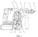
- FIG. 1 is a schematic sectional view of a percussion tool according to Embodiment 1 of the present invention.
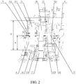
- FIG. 2 is a schematic partial view of a transmission mechanism in FIG. 1 .
- FIG. 3 is a schematic structural diagram of a percussion tool according to Embodiment 1 of the present invention.
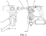
- FIG. 4 is a schematic exploded view of a percussion tool according to Embodiment 1 of the present invention.
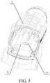
- FIG. 5 is a schematic structural diagram of a first housing in a percussion tool according to Embodiment 1 of the present invention. As shown in FIG. 1 to FIG. 5 , the percussion tool in this embodiment may specifically include the following parts and structures:
- the transmission mechanism 3 comprises a first intermediate shaft 31 configured to drive the striking mechanism 4.
- the first intermediate shaft 31 includes a first end close to the motor 1 and a second end away from the motor 1.
- the first end of the first intermediate shaft 31 is fixedly supported on the second housing 6, and shares, by using the second housing 6, a load that the first end is subjected to, and the second end of the first intermediate shaft 31 is set to be a free end such that the first intermediate shaft is configured as a cantilever.
- the percussion tool in this embodiment includes the motor 1 configured to drive rotation of the tool bit
- the motor 1 includes the motor shaft 11, the motor shaft 11 outputs power to the percussion tool through rotation of the motor shaft 11, to enable the tool bit 21 in the percussion tool to rotate, or partially or entirely provides the impact force for the tool bit 21 by using the striking mechanism 4, to implement impact motion.
- the output shaft 2 is configured to accommodate the tool bit 21, and drive the tool bit 21 to perform an operation such as rotation.
- An axis of the output shaft 2 is not parallel to an axis of the motor shaft 11 in the motor 1, but instead an angle is defined between the axis of the output shaft 2 and the axis of the motor shaft 11.
- the motor 1 is not located in a direction of an extension line of the output shaft 2, but is located on one side of the output shaft 2, for example, close to a bottom position of the percussion tool.
- the output shaft 2 and the tool bit 21 are both located at a front end of the percussion tool, and the motor 1 is located at a bottom position at a rear end of the percussion tool, so that the entire percussion tool is in a vertical construction.
- the angle between the output shaft 2 and the motor shaft 11 ranges from 80° to 100°.
- the output shaft 2 is perpendicular to the motor shaft 11. In this way, it can be ensured that the percussion tool is relatively short and has a relatively compact structure.
- the percussion tool may further include a plurality of housings having different shapes and structures, including the first housing 5 configured to accommodate at least part of the striking mechanism 4, the second housing 6 configured to support the transmission mechanism 3, and the third housing 7 configured to accommodate the at least a part of the motor 1.
- the second housing 6, the first housing 5, and the third housing 7 may be connected to each other by using a connecting piece and the like, to form a complete housing structure.
- the first housing 5 may be configured to accommodate and protect at least part of the striking mechanism 4. Therefore, the first housing 5 generally has a relatively large volume and has a case or shell structure having a hollow cavity. In addition, the striking mechanism 4 and all or at least a part of the output shaft 2 are disposed inside the hollow cavity of the first housing 5. In this way, to match the angle between the output shaft 2 and the motor shaft 11 while accommodating the striking mechanism 4 and the output shaft 2, the first housing 5 generally has an "L"-shaped structure.
- One end of the "L"-shaped structure is parallel to the output shaft or in a same direction as that of the output shaft to accommodate all or a part of the output shaft 2, and the other end of the "L"-shaped structure faces a lower portion of the percussion tool and is configured to connect to parts such as the second housing 6.
- the second housing 6, as a main supporting part of the transmission mechanism 3, can bear most rotation and an alternating load of the transmission mechanism 3 to prevent the transmission mechanism 3 from being unstable, for example, moving, due to the impact of the load.
- the second housing 6 may be of a relatively simple shape, for example, an intermediate cover having a relatively small thickness and a relatively simple structure.
- the second housing 6 as the intermediate cover may be connected to a bottom end of the first housing 5, and encloses, together with the first housing 5, a cavity configured to accommodate parts such as the striking mechanism 4.
- the first housing 5 and the second housing 6 may be connected to each other by using a connecting piece 8 and the like.
- the connecting piece 8 may be a screw or the like. The screw connects the first housing 5 to the second housing 6 along a direction parallel to the motor shaft 11.
- the third housing 7 may cover a surface of the motor 1 and accommodate at least a part of the motor 1, to protect the motor 1. Therefore, the third housing is generally a thin shell-like structure bearing less force.
- the percussion tool To connect the output shaft 2 to the motor shaft 11, the percussion tool includes the transmission mechanism 3, and the transmission mechanism can implement connection motion converting and power output between the output shaft 2 and the motor shaft 11 by using motion converting structures such as an intermediate shaft and a gear.
- the transmission mechanism 3 generally includes a plurality of intermediate shafts, and different intermediate shaft may be respectively configured to output rotation power to the output shaft 2, or drive the striking mechanism 4 to impact.
- the transmission mechanism 3 includes the first intermediate shaft 31 configured to drive the striking mechanism 4, the first intermediate shaft 31 includes the first end close to the motor 1 and the second end away from the motor 1, the first end of the first intermediate shaft 31 is fixedly supported on the second housing 6, and the second end of the first intermediate shaft 31 is set to be the cantilever.
- the second end of the first intermediate shaft 31 is not connected to the first housing 5, but is set to an impending cantilever. In this way, when the impending second end of the first intermediate shaft 31 bears alternating load, the second end does not transmit the load to the first housing 5.
- the transmission mechanism further comprises a crank hub 311 or another eccentric structure used for circularly moving around an axle center of the first intermediate shaft 31 which is disposed at the second end of the first intermediate shaft 31, and the crank hub 311 is eccentrically disposed relative to the axle center of the first intermediate shaft 31.
- the first intermediate shaft 31 and the second housing 6 are relatively fixed, and the crank hub 311 may be driven by a transmission mechanism such as a gear to circularly move.
- the crank hub 311 is connected to a connecting piece such as an oscillating bar.
- the circular motion of the crank hub 311 may drive the connecting piece such as the oscillating bar to oscillate, so that the circular motion of the crank hub 311 is converted into a linear reciprocating motion of a part in the striking mechanism 4, drives a piston in the striking mechanism 4 to circularly move in a cylinder, and implement gas compression.
- gas generates a cyclic reciprocating pneumatic impact force.
- the impact force may be applied to the tool bit 21, and enable the tool bit 21 to generate an impact effect on a to-be-drilled surface to improve a drilling capability.
- a bearing 312 is generally disposed between the first intermediate shaft 31 and the crank hub 311.
- the percussion tool has different operation modes.
- the intermediate shaft may be connected to or disconnected from different motion converting parts through switching of a clutch mechanism, to respectively drive, by the intermediate shaft driven by rotation of the motor shaft 11, a corresponding motion converting part and the tool bit 21 to perform one or more of rotation or linear reciprocating motion, so that the percussion tool performs a corresponding drilling or impact function.
- the second housing 6 generally has a rigid structure made from a high-strength material.
- the first intermediate shaft 31 bears a load, most of the load received by the first intermediate shaft 31 may be transferred to the second housing 6. Therefore, relatively good supporting and unloading effects can be achieved.
- the first intermediate shaft 31 can implement relatively stable rotation, power output is relatively smooth, and security is relatively good.
- the second housing 6 needs to bear, by using the first intermediate shaft 31, a high-strength alternating load when the striking mechanism 4 moves. Therefore, the second housing 6 is generally a metal material to ensure that the second housing 6 has a good mechanical property and relatively high strength.
- the first intermediate shaft 31 is a cantilever structure, and is not connected to the first housing 5. In this way, an alternating load applied to the first housing 5 from the first intermediate shaft 31 is relatively small. In this way, a main function of the fist housing 5 is to form a sealed cavity to protect motion parts such as the striking mechanism 4 and the output shaft 2, and implement fixing and auxiliary supporting of the transmission mechanism 3. In this way, both the first housing 5 and the third housing 7 may be made of plastics that have force bearing performance and relatively small mass.
- a housing structure for example, a gear box housing
- parameters such as an overall volume and wall thickness of the first housing 5 made of a light plastic material may approximate to or keep consistent with those in the prior art, but the weight is greatly reduced.
- Plastic may be made through synthesis of two components, nylon and glass fiber, may be made through synthesis of two components, nylon and carbon fiber, may be made from other components, or the like.
- the plastic may be made through the synthesis of the two components, nylon and glass fiber. Glass fiber accounts for 45% of total components, and nylon accounts for 55% of the total components. In this way, strength of the plastic can be higher to satisfy a strength requirement when the percussion tool is operated.
- the plastic has advantages such as a relatively small weight, good chemical stability, and being easily processed and formed, and can still ensure a mechanical property when being relatively light. Therefore, the plastic can be used for positioning and fixing motion converting parts in the first housing 5 and the motor 1 in the third housing 7 while ensuring relatively small mass.
- the second housing 6 may be made of a magnesium alloy material or an aluminium alloy material. Magnesium alloy and aluminium alloy have a good mechanical property, relatively high strength, and a relatively small weight.
- the second housing 6 may be a cover-shaped structure, that is, an intermediate cover, connected between the first housing 5 and the third housing 7.
- the first intermediate shaft 31 is fixed on the second housing 6, and is supported by the second housing 6.
- a structure such as the crank hub 311 on the first intermediate shaft 31 drives the striking mechanism 4 to impact
- an alternating load reacted by the striking mechanism 4 on the first intermediate shaft 31 is received and absorbed by the second housing 6, and the first housing 5 only needs to ensure positioning and fixing of the striking mechanism 4 and the output shaft 2 and bears a relatively small load.
- the first housing 5 does not need to bear a relatively large load any more. Therefore, the first housing 5 of a case or shell structure and of relatively large volume may be made of a relatively light material, and only needs to ensure a load bearing capability of the second housing 6 having a relatively small volume proportion. In this way, the weight of the entire tool can be significantly reduced, so that an operator can easily implement holding with one hand or operation at a high position.
- At least one end portion of the first intermediate shaft 31 is connected to the second housing 6.
- the second housing 6 is generally connected between the transmission mechanism 3 and the motor 1. Therefore, a position at which the second housing 6 is located is generally on one side of the entire transmission mechanism 3.
- the second housing 6 may be connected to the at least one end portion of the first intermediate shaft 31, and separately supports the first intermediate shaft 31 from the end portion and bears the load in the first intermediate shaft 31.
- the transmission mechanism 3 includes the plurality of intermediate shafts
- other intermediate shafts may also be supported and fixed in a similar manner, or the second housing 6 and other parts may cooperate to fix the intermediate shafts and bear a load.
- a fixing structure is disposed on the second housing 6, the first intermediate shaft 31 is fixed on the fixing structure and is fixedly connected to the fixing structure.
- fixing between the first intermediate shaft 31 and the fixing structure is implemented through interference fitting and the like.
- the crank hub 311 connected to an end portion of the first intermediate shaft 31 is rotatable relative to the second housing 6, to drive the percussion tool to impact.
- the fixing structure may be a structure, for example, a hole, a groove, or a cavity, that can fix the end portion of the first intermediate shaft 31 in the structure.
- the second housing 6 may be provided with an accommodation groove 61, and the accommodation groove 61 is used for accommodating the first end of the first intermediate shaft 31.
- the first intermediate shaft 31 in the transmission mechanism 3 is generally disposed parallel or approximately parallel to the axis of the motor shaft 11, and motion converting rotation between the crank hub 311 on the first intermediate shaft 31 and the motor shaft 11 is generally implemented in a manner of gear engaging or the like.
- the second housing 6 is provided with an axle hole for the motor shaft 11 of the motor 1 to pass through, and the accommodation groove 61 is located on a side of the axle hole.
- the motor 1 is located below the second housing 6, and the motor shaft 11 of the motor 1 extends out of the second housing 6 via the axle hole, and extends into a cavity area inside the first housing.
- the first intermediate shaft 31 disposed parallel to the motor shaft 11 may be fixed in the accommodation groove 61 located on the side of the axle hole.
- a distance between the accommodation groove 61 and the axle hole may be correspondingly set based on a spacing between the first intermediate shaft 31 and the motor shaft 11.
- the size and shape of the axle hole match those of the motor shaft 11, so that the motor shaft 11 can be fixed by using the axle hole.
- the size of the axle hole may match a diameter of the motor shaft 11 of the motor 1, to limit displacement in a radial direction of the motor shaft 11.
- the motor shaft 11 needs to provide driving power through rotation. Therefore, a bearing 111 may further be generally disposed between the axle hole and the motor shaft 11, so that the motor shaft 11 can freely rotate in the axle hole.
- the bearing 111 in the axle hole may be a rolling bearing, a sliding bearing, or the like.
- a limiting structure such as a stepped surface or a protrusion is generally further disposed on the axle hole of the second housing 6.
- some sealing structures for example, a sealing ring or a sealing pad, are generally further disposed in the axle hole.
- an opening direction of the accommodation groove 61 generally faces the first intermediate shaft 31, so that the end portion of the first intermediate shaft 31 is placed in the accommodation groove 61 through the opening.
- the end portion of the first intermediate shaft 31 is fixed by the accommodation groove 61 after inserted into the accommodation groove 61, so that an alternating load generated when the first intermediate shaft 31 rotates can be transmitted to the second housing 6 through the accommodation groove 61 and then be transmitted to the entire percussion tool through the second housing 6. Therefore, the first intermediate shaft 31 is effectively positioned and fixed and can disperse the load that the first intermediate shaft 31 is subjected to.
- a ratio of a depth h of the accommodation groove 61 to a total height H of the first intermediate shaft 31 is generally greater than or equal to 1/3, to ensure that the first intermediate shaft 31 can be stably fixed by the accommodation groove 61 without waggling or the like.
- a ratio of a height of the accommodation groove 61 to the total height of the first intermediate shaft 31 is 1/2. In this way, the first intermediate shaft 31 is stably supported by the accommodation groove 61, and the second housing 6 can maintain relatively small thickness and a relatively small volume and weight, helping reduce the weight of the percussion tool.
- An insert 71 is disposed between the first intermediate shaft 31 and the accommodation groove 61, and the insert 71 is sleeved over the first intermediate shaft 31.
- the insert 71 is made of a metal material, for example, a steel material.
- the insert 71 and the first intermediate shaft 31 are integrally formed, and are inserted into the accommodation groove 61 together when assembled. Disposing of the insert 71 can make the first intermediate shaft 31 more stably supported, and is beneficial to reducing a load of the first housing 5, so that most of the alternating load reacted by the striking mechanism 4 on the first intermediate shaft 31 is received by the second housing 6.
- the transmission mechanism 3 further includes a second intermediate shaft 32 configured to drive the output shaft 2 to rotate, the second intermediate shaft 32 includes a first end close to the motor 1 and a second end away from the motor 1, the first end of the second intermediate shaft 32 is movably supported on the second housing 6, and the second end of the second intermediate shaft 32 is movably supported on the first housing 5.
- the second intermediate shaft 32 needs to rotate around an axle center, to drive the output shaft 2 to rotate.
- the second intermediate shaft 32 is relatively long, because the volume and the thickness of the second housing 6 are relatively small, one end portion of the second intermediate shaft 32 is generally fixed on the second housing 6, and the other end portion of the second intermediate shaft 32 is fixed and connected by using the first housing 5 or other structures.
- the first intermediate shaft 31 and the second intermediate shaft 32 are generally disposed on two sides of the motor shaft 11, and the first intermediate shaft 31 and the second intermediate shaft 32 obtain power from the motor shaft 11 in a motion converting manner such as gear engagement.
- the first intermediate shaft 31 obtains, through engagement between a first gear 312 and a small gear 112 on the motor shaft 11, power generated by the motor 1, and the second intermediate shaft 32 obtains, through engagement between a second gear 321 and the small gear 112 on the motor shaft 11, the power generated by the motor 1, and transmit the power to corresponding parts through connection to other parts and structures, thereby respectively implementing rotation and impact of the tool bit 21.
- axle center directions of the second intermediate shaft 32 and the motor shaft 11 are both set along a vertical direction, the motor shaft 11 and the motor 1 are generally disposed in a downmost area of the striking mechanism 4, and the transmission mechanism 3, the first housing 5 and the like are disposed above the motor 1.
- a bottom end of the second intermediate shaft 32 is generally connected to the second housing 6, that is, the intermediate cover.
- the bottom end of the second intermediate shaft 32 is movably supported on the second housing 6, and a top end of the second intermediate shaft 32 is movably supported on the first housing 5 and is connected to the transmission mechanism 3 or the output shaft 2.
- first intermediate shaft 31, the second intermediate shaft 32, and the motor shaft 11 lie in a same plane, and gear centers of the first gear 312, the second gear 321, and the small gear 112 are located on one straight line. Such disposing can make each gear uniformly forced when engaged with the motor shaft, thereby improving a service life of each gear.
- an accommodation cavity 62 may be disposed on the second housing 6, and a connecting piece is provided between the second intermediate shaft 32 and the accommodation cavity 62.
- the structure and the shape of the accommodation cavity 62 are similar to those of the accommodation groove 61.
- the accommodation cavity 62 has an opening facing the second intermediate shaft 32, so that the end portion of the second intermediate shaft 32 can enter the accommodation cavity 62 from the opening and be accommodated in the accommodation cavity 62.
- the connecting piece is provided between the second intermediate shaft 32 and the accommodation cavity 62, and the connecting piece can ensure that the second intermediate shaft 32 can freely rotate relative to cavity walls of the accommodation cavity 62.
- the connecting piece may be various different patterns and structures, provided that the connecting piece can fix the second intermediate shaft 32 in the accommodation cavity 62, and implement free rotation between the second intermediate shaft 32 and the accommodation cavity 62. This is not limited in this embodiment.
- the connecting piece may be a bearing 621.
- the second intermediate shaft 32 needs to remain rotatably disposed in the accommodation cavity 62. Therefore, the bearing 621 is generally disposed between the accommodation cavity 62 and the end portion of the second intermediate shaft 32. In this way, a bearing chamber configured to accommodate the bearing 621 is formed inside the accommodation cavity 62.
- An outer ring of the bearing 621 is generally directly connected to the cavity wall of the accommodation cavity 62, an inner ring of the bearing 621 is sleeved over outer sides of the end portions of the second intermediate shaft 32, and inner and outer rings of the bearing 621 may be slidably connected to each other, or implement rolling connection by using a roll ball or a roller pin. In this way, under the action of the bearing 621, the second intermediate shaft 32 and the second housing 6 may remain fixed and relatively rotate.
- the bearing 621 configured to connect the second intermediate shaft 32 to the accommodation cavity 62 may have various different types.
- the rolling bearing may be specifically a deep groove ball bearing, a needle bearing, a tapered roller bearing, or the like.
- the second intermediate shaft 32 When driving the tool bit 21 to implement a drilling operation, the second intermediate shaft 32 performs rotation motion around a rotation axis of the second intermediate shaft 32 throughout under power of the motor 1. Therefore, the second intermediate shaft 32 may directly drive, by using a motion converting manner such as gear connection, the output shaft 2 to rotate, to perform the drilling operation.
- a structure helping fix the second intermediate shaft 32 needs to be disposed on the first housing 5.
- a partition board 51 is disposed on the first housing 5, the partition board 51 is provided with a through hole 52 for the second intermediate shaft 32 to pass through.
- the second intermediate shaft 32 may be fixed by the through hole 52 on the partition board 51.
- the second intermediate shaft 32 may be supported by two independent supporting points located at different portions along an axial direction of the second intermediate shaft 32. Therefore, the second intermediate shaft 32 can maintain a stable gesture when rotating, to avoid inclining, inverting, transversely moving, and so on.
- the first housing 5 only needs to be configured to stabilize a gesture of the second intermediate shaft 32 to prevent the second intermediate shaft 32 from inverting. Load received by the partition board 51 and the through hole 52 is relatively small. Even though the first housing 5 is made of plastic, stable supporting of the second intermediate shaft 32 can be similarly ensured.
- partition board 51 may be connected to and fixed on different portions on the second intermediate shaft 32.
- the partition board 51 is mainly configured to resist moment of force of inclination and deflection of the second intermediate shaft 32 around the end portions. Based on the lever principle, when an acting force applied by the partition board 51 is at the end portion of the second intermediate shaft 32, a required acting force is smallest. Therefore, in an optional manner, the partition board 51 is movably connected to an end portion of the second intermediate shaft 32 away from the second housing 6. In this way, the first housing 5 and the second housing 6 may be respectively fixed on two end portions of the second intermediate shaft 32, and support and position the second intermediate shaft 32.
- the first housing 5 may specifically include the partition board 51, and the partition board 51 is provided with the through hole 52 for the second intermediate shaft 32 to pass through.
- the second intermediate shaft 32 can pass through the through hole 52, and be fixed on and connected to the first housing 5 by using the partition board 51.
- a direction of the partition board 51 and the axial direction of the second intermediate shaft 32 are alternative with each other and even perpendicular to each other. In this way, a direction of the through hole 52 provided on the partition board 51 remains consistent with the direction of the second intermediate shaft 32, thereby achieving a relatively good fixing effect.
- an edge of the partition board 51 is generally connected to a case wall of the first housing 5, or directly forms a part of the case wall of the first housing 5.
- a lateral force or torque that the partition board 51 is subjected to may be both transmitted to the first housing 5. Therefore, the second intermediate shaft 32 can be fixed and positioned by the first housing 5 by using the partition board 51, and the positioning effect is relatively good.
- the partition board 51 and the first housing 5 may be integrally formed, or may be detachably disposed as separate members.
- the partition board 51 may be a plate, or may be an arcuate plate having a particular radian.
- the partition board 51 is generally located at a lower position of the first housing 5, and matches the lower shape of the first housing 5.
- the second intermediate shaft 32 needs to remain in a rotation state when the percussion tool drills.
- a bearing 521 may also be disposed between the through hole 52 on the partition board 51 and the second intermediate shaft 32.
- An outer ring of the bearing 521 is generally directly connected to a hole wall of the through hole 52, an inner ring of the bearing 521 is sleeved over an outer side of the second intermediate shaft 32, and inner and outer rings of the bearing 521 may be slidably or rollingly connected to each other. In this way, under the action of the bearing 521, the second intermediate shaft 32 and the through hole 52 can maintain relative rotation, so that the second intermediate shaft 32 is flexibly supported on the first housing 5.
- the bearing 521 disposed in the through hole 52 may similarly have different types, for example, a deep groove ball bearing, a needle bearing, a tapered roller bearing, or the like.
- the type and the size of the bearing 521 may be correspondingly selected based on the size of the second intermediate shaft 32 and a feature of load received.
- a mounting structure configured to mount the bearing 521 may be generally disposed on the through hole 52.
- one end of the through hole 52 may form an accommodation cavity used for accommodating the bearing 521.
- different ends of the through hole 52 along an axial direction have different apertures. An aperture of one end is relatively small, an aperture of the other end is relatively large, and a stepped surface generally exists between the two ends of the different apertures. In this way, the end having the relatively large aperture may form the accommodation cavity used for accommodating the bearing 521.
- first intermediate shaft 31 and the second intermediate shaft 32 can be both supported by the second housing 6. Therefore, torque and an alternating load received by the first intermediate shaft 31 and the second intermediate shaft 32 can also be transmitted to the second housing 6 to maintain normal rotation of the crank hub 311 and the second intermediate shaft 32.
- first intermediate shaft 31 and the second intermediate shaft 32 can also be helped to be positioned and supported by a housing wall of the first housing 5 or other motion converting parts. In this way, it can be ensured that the percussion tool implements normal operations, for example, drilling and impact, without requiring the first housing 5 to share and support a load on the transmission mechanism 3. Therefore, the structural weight of the first housing 5 can be greatly reduced, to satisfy requirements of lightness and miniaturization of the percussion tool.
- the percussion tool includes the motor, including the motor shaft; the output shaft, disposed at the angle relative to the motor shaft, and configured to accommodate the tool bit; the transmission mechanism, disposed between the motor shaft and the output shaft; the striking mechanism, configured to provide the impact force for the tool bit; the first housing, configured to accommodate the striking mechanism and the at least a part of the output shaft; the second housing, connected to the first housing, and configured to support the transmission mechanism; and the third housing, connected to the second housing, and configured to accommodate the at least a part of the motor.
- the transmission mechanism includes the first intermediate shaft configured to drive the striking mechanism, the first intermediate shaft includes the first end close to the motor and the second end away from the motor, the first end of the first intermediate shaft is fixedly supported on the second housing, and the second end of the first intermediate shaft is set to be the cantilever.
- the first intermediate shaft of the transmission mechanism is supported on the second housing in a relatively small volume to reduce the structural weight of the first housing in a relatively large volume and significantly reduce the weight of the entire tool while ensuring normal operation of the percussion tool, so that an operator can easily implement holding with one hand or operation at a high position.
- This embodiment provides a percussion tool that can achieve a relatively small weight to facilitate operation by an operator.
- the percussion tool in this embodiment is similar to that in the foregoing Embodiment 1. Therefore, FIG. 1 to FIG. 4 in the foregoing description are still used for description.
- the percussion tool in this embodiment specifically includes the following parts:
- the transmission mechanism 3 comprises a first intermediate shaft 31 configured to drive the striking mechanism 4, the first intermediate shaft 31 is parallel to the motor shaft 11, the first housing 5 and the third housing 7 are made of plastic materials, and the second housing 6 is made of a metal material.
- the percussion tool in this embodiment includes the motor 1 configured to drive the tool bit 21 to rotate
- the motor 1 includes the motor shaft 11, the motor shaft 11 outputs power to the percussion tool through rotation of the motor shaft 11, to enable the tool bit 21 in the percussion tool to rotate, or generates the impact force for the tool bit 21 by using the striking mechanism, to implement impact motion.
- the output shaft 2 is configured to accommodate the tool bit 21, and drive the tool bit 21 to perform an operation such as rotation.
- An axis of the output shaft 2 is not parallel to an axis of the motor shaft 11 in the motor 1, but instead an angle is defined between the axis of the output shaft 2 and the axis of the motor shaft 11.
- the motor is located on one side of the output shaft 2, for example, close to a bottom position of the percussion tool.
- the output shaft 2 and the tool bit 21 may be both located at a front end of the percussion tool, and the motor 1 is located at a bottom position at a rear end of the percussion tool, so that the entire percussion tool is in a vertical structure.
- the angle between the output shaft 2 and the motor shaft 11 ranges from 80° to 100°.
- the output shaft 2 is perpendicular to the motor shaft 11. In this way, it can be ensured that the percussion tool is relatively short and has a relatively compact structure.
- the percussion tool may further include a plurality of housings having different shapes and structures, including the first housing 5 configured to accommodate the output shaft 2, the second housing 6 configured to support the transmission mechanism 3, and the third housing 7 configured to accommodate the at least a part of the motor 1. Connections exist between the second housing 6, the first housing 5, and the third housing 7. Therefore different housings may be connected to each other to form a complete housing structure.
- the first housing 5 may be configured to accommodate and protect the at least a part of the output shaft 2. Therefore, the first housing 5 generally has a case or shell structure having a hollow cavity, and the output shaft 2 is disposed inside the hollow cavity of the first housing 5.
- the second housing 6, as a main supporting part of the transmission mechanism 3, can bear most rotation and an alternating load of the transmission mechanism 3 to prevent the transmission mechanism 3 from being unstable, for example, moving, due to the impact of the load.
- the third housing 7 may cover a surface of the motor 1 and accommodate at least a part of the motor 1, to protect the motor 1.
- the third housing 7 is further configured to dispose a structural accessory such as a handle.
- the percussion tool includes the transmission mechanism 3, and the transmission mechanism can implement connection motion converting and power output between the output shaft 2 and the motor shaft 11 by using motion converting structures such as an intermediate shaft and a gear.
- the transmission mechanism 3 includes the first intermediate shaft 31 configured to drive the striking mechanism 4, and the first intermediate shaft 31 is parallel to the motor shaft 11. That is, the first intermediate shaft 31 and the motor shaft 11 each are disposed at an angle relative to the output shaft 2.
- the first intermediate shaft 31 in the transmission mechanism 3 is parallel to the motor shaft 11, and the angle is formed between each of the first intermediate shaft 31 and the motor shaft 11 and the output shaft 2. Therefore, the first housing 5 configured to accommodate the at least a part of the output shaft 2 generally may be of an "L"-shaped structure or the like, to accommodate the output shaft 2 and connect to a structure such as the second housing 6.
- the second housing 6 may be of a plate-like or cover-like structure having a relatively simple shape and a relatively small volume, and does not need to form a relatively complex structure such as an "L"-shaped structure.
- the second housing 6 may be connected to the first housing 5 by using a connecting piece, and the connecting piece is connected to the first housing 5 and the second housing 6 along a direction parallel to the motor shaft 11.
- the second housing 6 may be of the plate-like or cover-like structure having the relatively simple structure. Therefore, the second housing 6 may be connected to and fixed on the first housing 5 by using a connecting piece 8 along the direction parallel to the motor shaft 11, that is, a vertical direction.
- the connecting piece 8 may be a screw or another threaded fastener, and correspondingly, the second housing 6 and the first housing 5 may be provided with mounting holes corresponding to the screw.
- the second housing 6 needs to bear a high-strength alternating load. Therefore, the second housing 6 is generally a metal material to ensure that the second housing 6 has a good mechanical property and relatively high strength. Most of a load of the transmission mechanism 3 during motion is received by the second housing 6. Therefore, the first housing 5 does not need to bear an excessive load and moment of force of rotation any more.
- a main function of the first housing 5 is to form a sealed cavity to protect a motion part such as the output shaft 2 in the transmission mechanism 3, and implement fixing and auxiliary supporting of the transmission mechanism 3.
- both the first housing 5 and the third housing 7 may be made of plastics that have force bearing performance and relatively small mass.
- a housing structure for example, a gear box housing
- parameters such as an overall volume and wall thickness of the first housing 5 made of a light plastic material may approximate to or keep consistent with those in the prior art, but the weight is greatly reduced.
- Plastic may be made through synthesis of two components, nylon and glass fiber, may be made through synthesis of two components, nylon and carbon fiber, may be made from other components, or the like.
- the plastic is made through the synthesis of the two components, nylon and glass fiber. Glass fiber accounts for 45% of total components, and nylon accounts for 55% of the total components. In this way, strength of the plastic can be higher to satisfy a strength requirement when the percussion tool is operated.
- the plastic has advantages such as a relatively small weight, good chemical stability, and being easily processed and formed, and can still ensure a mechanical property when being relatively light. Therefore, the plastic can be used for positioning and fixing motion converting parts in the first housing 5 and the motor in the third housing 7 while ensuring relatively small mass.
- the second housing 6 may be a magnesium alloy material or an aluminium alloy material. Magnesium alloy and aluminium alloy have a good mechanical property, relatively high strength, and a relatively small weight.
- the second housing 6 may be a cover-shaped structure, that is, an intermediate cover, connected between the first housing 5 and the third housing 7.
- the transmission mechanism 3 is fixed on the second housing 6, and is supported by the second housing 6.
- a load that the transmission mechanism 3 is subjected to is received and absorbed by the second housing 6, and the first housing 5 only needs to ensure positioning and fixing of the transmission mechanism 3 and the output shaft 2 and bears a relatively small load.
- the first housing 5 does not need to bear a relatively large load any more. Therefore, the first housing 5 of a case or shell structure and of relatively large volume may be made of a relatively light material, and only needs to ensure a load bearing capability of the second housing 6 having a relatively small volume proportion. In this way, the weight of the entire tool can be significantly reduced, so that an operator can easily implement holding with one hand or operation at a high position.
- the percussion tool specifically includes the following parts: the motor, including the motor shaft; the output shaft, disposed at the angle relative to the motor shaft, and configured to accommodate the tool bit; the transmission mechanism, disposed between the motor shaft and the output shaft; the striking mechanism, configured to provide the impact force for the tool bit; the first housing, configured to accommodate the at least a part of the output shaft; the second housing, connected to the first housing, and configured to support the transmission mechanism; and the third housing, connected to the second housing, and configured to accommodate the at least a part of the motor.
- the transmission mechanism includes the first intermediate shaft configured to drive the striking mechanism, the first intermediate shaft is parallel to the motor shaft, the first housing and the third housing are plastic materials, and the second housing is the metal material.
- the first housing is made of plastic having a relatively small weight, to significantly reduce the weight of the entire tool while ensuring normal operation of the percussion tool, so that an operator can easily implement holding with one hand or operation at a high position.
- connection may be fixed connection, detachable connection, integrated connection, or the like.
- connection may represent direct connection, indirect connection implemented by using an intermediary, or the like. Persons skilled in the art may understand specific meanings of the foregoing terms in this application based on specific situations.
Landscapes
- Engineering & Computer Science (AREA)
- Mechanical Engineering (AREA)
- Percussive Tools And Related Accessories (AREA)
- Earth Drilling (AREA)
Abstract
Description
- The present invention relates to the field of electric tools, and in particular, to a percussion tool.
- With continuous development of science and technology, electric tools such as hammer tools increasingly emerge in works such as civil engineering due to features of relatively high operation efficiency and relatively flexible use.
- Currently, to adapt to building materials having relatively high strength, for example, concrete and brick walls, the hammer tools are generally used for working. A hammer tool generally includes mechanical parts such as a housing, a gear box and an intermediate cover and motion parts such as a motor and a transmission mechanism. Relative stabilization between the motor and the transmission mechanism is maintained generally depending on the intermediate cover, the transmission mechanism is disposed in a cavity enclosed by the gear box and the intermediate cover, and an intermediate shaft in the transmission mechanism is fixed and supported depending on the gear box. To bear a large quantity of an alternating load generated when the intermediate shaft rotates or strikes, the gear box and the intermediate cover are generally made of high-strength metal to ensure reliability of positioning of the intermediate shaft.
- However, the current hammer tools have relatively larger mass. This does not facilitate holding by an operator with one hand or operation by using a posture at a high position. In many relatively complex civil construction sites, use is limited.
- The present invention provides a percussion tool that has a relatively small weight and is relatively flexibly used.
- According to a first aspect, the present invention provides a percussion tool, including:
- a motor including a motor shaft and configured to output a power;
- an output shaft disposed at an angle relative to the motor shaft and configured to accommodate a tool bit;
- a striking mechanism configured to provide an impact force for the tool bit;
- a transmission mechanism disposed between the motor shaft and the output shaft and configured to transmit the power to the striking mechanism;
- a first housing configured to accommodate at least part of the striking mechanism;
- a second housing connected to the first housing and configured to support the transmission mechanism; and
- a third housing connected to the second housing, and configured to accommodate at least a part of the motor, where
- the transmission mechanism includes a first intermediate shaft for driving the striking mechanism, the first intermediate shaft includes a first end which is close to the motor and a second end which is away from the motor, the first end is fixedly supported on the second housing, and the second end is set to be a free end such that the first intermediate shaft is configured as a cantilever.
- According to a second aspect, the present invention provides a percussion tool, including
- a motor including a motor shaft and configured to output a power;
- an output shaft disposed at an angle relative to the motor shaft and configured to accommodate a tool bit;
- a striking mechanism configured to provide an impact force for the tool bit;
- a transmission mechanism disposed between the motor shaft and the output shaft and configured to transmit the power to the striking mechanism;
- a first housing configured to accommodate at least a part of the output shaft;
- a second housing connected to the first housing, and configured to support the transmission mechanism; and
- a third housing connected to the second housing, and configured to accommodate at least a part of the motor, where
- the transmission mechanism includes a first intermediate shaft configured to drive the striking mechanism, the first intermediate shaft is parallel to the motor shaft, the first housing and the third housing are plastic materials, and the second housing is a metal material.
- According to some embodiments, the percussion tool in the present invention includes: the motor, including the motor shaft and configured to output a power; the output shaft disposed at the angle relative to the motor shaft and configured to accommodate the tool bit; the striking mechanism configured to provide the impact force for the tool bit; the transmission mechanism disposed between the motor shaft and the output shaft and configured to transmit the power to the striking mechanism; the first housing configured to accommodate at least a part of the striking mechanism; the second housing connected to the first housing and configured to support the transmission mechanism; and the third housing, connected to the second housing, and configured to accommodate the at least a part of the motor. The transmission mechanism may include the first intermediate shaft configured to drive the striking mechanism, the first intermediate shaft may include the first end close to the motor and the second end away from the motor, the first end of the first intermediate shaft may be fixedly supported on the second housing, and the second end of the first intermediate shaft may be set to be a free end such that the first intermediate shaft is configured as a cantilever. In this way, the first intermediate shaft of the transmission mechanism may be supported on the second housing in a relatively small volume, to reduce the structural weight of the first housing in a relatively large volume and significantly reduce the weight of the entire tool while ensuring normal operation of the percussion tool, so that an operator can easily implement holding with one hand or operation at a high position.
- To describe the technical solutions in the embodiments of the present invention or in the prior art more clearly, the following briefly describes the accompanying drawings required for describing the embodiments or the prior art. Apparently, the accompanying drawings in the following description show some embodiments of the present invention, and persons of ordinary skill in the art may still derive other drawings from these accompanying drawings without creative efforts.
-
FIG. 1 is a schematic sectional view of a percussion tool according toEmbodiment 1 of the present invention; -
FIG. 2 is a schematic partial view of a transmission mechanism inFIG. 1 ; -
FIG. 3 is a schematic structural diagram of a percussion tool according toEmbodiment 1 of the present invention; -
FIG. 4 is a schematic exploded view of a percussion tool according toEmbodiment 1 of the present invention; and -
FIG. 5 is a schematic structural diagram of a gear box in a percussion tool according toEmbodiment 1 of the present invention. -
- 1: Motor;
- 2: Output shaft;
- 3: Transmission mechanism;
- 4: Striking mechanism;
- 5: First housing;
- 6: Second housing;
- 7: Third housing;
- 8: Connecting piece;
- 11: Motor shaft;
- 21: Tool bit;
- 31: First intermediate shaft;
- 32: Second intermediate shaft;
- 51: Partition board;
- 52: Through hole;
- 61: Accommodation groove;
- 62: Accommodation cavity;
- 71: Insert;
- 111, 312, 521, and 621: Bearings;
- 112: Small gear;
- 311: Crank hub;
- 312: First gear; and
- 321: Second gear.
- To make the objectives, technical solutions, and advantages of the embodiments of the present invention clearer, the following clearly and completely describes the technical solutions in the embodiments of the present invention with reference to the accompanying drawings in the embodiments of the present invention. Apparently, the described embodiments are some but not all of the embodiments of the present invention. All other embodiments obtained by persons of ordinary skill in the art based on the embodiments of the present invention without creative effects shall fall within the protection scope of the present invention.
- A percussion tool, as a common electric tool, may be applied to a civil working site in which construction by using a general electric drill is relatively difficult because concrete, a brick structure, and the like have relatively large hardness. To drill into building materials of relatively large hardness, in addition to a common electric drill, the percussion tool further includes a pneumatic striking mechanism to implement rotating impact works. Specially, the pneumatic striking mechanism mainly impacts the drill by using compressed gas according to the principle of piston motion, so that the drill impacts a to-be-drilled surface. Generally, the percussion tool may form a hole of a diameter ranging from 6 mm to 100 mm on the concrete or the brick material. The following describes a percussion tool in the present invention in detail by using specific embodiments.
-
FIG. 1 is a schematic sectional view of a percussion tool according toEmbodiment 1 of the present invention.FIG. 2 is a schematic partial view of a transmission mechanism inFIG. 1 .FIG. 3 is a schematic structural diagram of a percussion tool according toEmbodiment 1 of the present invention.FIG. 4 is a schematic exploded view of a percussion tool according toEmbodiment 1 of the present invention.FIG. 5 is a schematic structural diagram of a first housing in a percussion tool according toEmbodiment 1 of the present invention. As shown inFIG. 1 to FIG. 5 , the percussion tool in this embodiment may specifically include the following parts and structures: - a
motor 1 including a motor shaft 1land configured to outputs a power; - an
output shaft 2 disposed at an angle relative to themotor shaft 11, and configured to accommodate atool bit 21; - a
transmission mechanism 3 disposed between themotor shaft 11 and theoutput shaft 2; - a striking mechanism 4- configured to provide an impact force for the
tool bit 21, thestriking mechanism 4 includes theoutput shaft 2, a piston housed in theoutput shaft 2, a ram impacted by the piston intermittently and a beat piece which is impacted by the ram intermittently; - a
first housing 5 configured to accommodate the part ofstriking mechanism 4, wherein at least part ofoutput shaft 2 exposed to thefirst housing 5; - a
second housing 6 connected to thefirst housing 5, and configured to support thetransmission mechanism 3; and - a
third housing 7 connected to thesecond housing 6, and configured to accommodate at least a part of themotor 1. - The
transmission mechanism 3 comprises a firstintermediate shaft 31 configured to drive thestriking mechanism 4. The firstintermediate shaft 31 includes a first end close to themotor 1 and a second end away from themotor 1. The first end of the firstintermediate shaft 31 is fixedly supported on thesecond housing 6, and shares, by using thesecond housing 6, a load that the first end is subjected to, and the second end of the firstintermediate shaft 31 is set to be a free end such that the first intermediate shaft is configured as a cantilever. - Specifically, the percussion tool in this embodiment includes the
motor 1 configured to drive rotation of the tool bit, themotor 1 includes themotor shaft 11, themotor shaft 11 outputs power to the percussion tool through rotation of themotor shaft 11, to enable thetool bit 21 in the percussion tool to rotate, or partially or entirely provides the impact force for thetool bit 21 by using thestriking mechanism 4, to implement impact motion. - The
output shaft 2 is configured to accommodate thetool bit 21, and drive thetool bit 21 to perform an operation such as rotation. An axis of theoutput shaft 2 is not parallel to an axis of themotor shaft 11 in themotor 1, but instead an angle is defined between the axis of theoutput shaft 2 and the axis of themotor shaft 11. In this way, themotor 1 is not located in a direction of an extension line of theoutput shaft 2, but is located on one side of theoutput shaft 2, for example, close to a bottom position of the percussion tool. In this case, theoutput shaft 2 and thetool bit 21 are both located at a front end of the percussion tool, and themotor 1 is located at a bottom position at a rear end of the percussion tool, so that the entire percussion tool is in a vertical construction. - In an optional implementation, the angle between the
output shaft 2 and themotor shaft 11 ranges from 80° to 100°. Preferably, theoutput shaft 2 is perpendicular to themotor shaft 11. In this way, it can be ensured that the percussion tool is relatively short and has a relatively compact structure. - In addition, the percussion tool may further include a plurality of housings having different shapes and structures, including the
first housing 5 configured to accommodate at least part of thestriking mechanism 4, thesecond housing 6 configured to support thetransmission mechanism 3, and thethird housing 7 configured to accommodate the at least a part of themotor 1. - The
second housing 6, thefirst housing 5, and thethird housing 7 may be connected to each other by using a connecting piece and the like, to form a complete housing structure. - The
first housing 5 may be configured to accommodate and protect at least part of thestriking mechanism 4. Therefore, thefirst housing 5 generally has a relatively large volume and has a case or shell structure having a hollow cavity. In addition, thestriking mechanism 4 and all or at least a part of theoutput shaft 2 are disposed inside the hollow cavity of thefirst housing 5. In this way, to match the angle between theoutput shaft 2 and themotor shaft 11 while accommodating thestriking mechanism 4 and theoutput shaft 2, thefirst housing 5 generally has an "L"-shaped structure. One end of the "L"-shaped structure is parallel to the output shaft or in a same direction as that of the output shaft to accommodate all or a part of theoutput shaft 2, and the other end of the "L"-shaped structure faces a lower portion of the percussion tool and is configured to connect to parts such as thesecond housing 6. - The
second housing 6, as a main supporting part of thetransmission mechanism 3, can bear most rotation and an alternating load of thetransmission mechanism 3 to prevent thetransmission mechanism 3 from being unstable, for example, moving, due to the impact of the load. Thesecond housing 6 may be of a relatively simple shape, for example, an intermediate cover having a relatively small thickness and a relatively simple structure. Thesecond housing 6 as the intermediate cover may be connected to a bottom end of thefirst housing 5, and encloses, together with thefirst housing 5, a cavity configured to accommodate parts such as thestriking mechanism 4. Thefirst housing 5 and thesecond housing 6 may be connected to each other by using a connectingpiece 8 and the like. The connectingpiece 8 may be a screw or the like. The screw connects thefirst housing 5 to thesecond housing 6 along a direction parallel to themotor shaft 11. - The
third housing 7 may cover a surface of themotor 1 and accommodate at least a part of themotor 1, to protect themotor 1. Therefore, the third housing is generally a thin shell-like structure bearing less force. - To connect the
output shaft 2 to themotor shaft 11, the percussion tool includes thetransmission mechanism 3, and the transmission mechanism can implement connection motion converting and power output between theoutput shaft 2 and themotor shaft 11 by using motion converting structures such as an intermediate shaft and a gear. - Specifically, the
transmission mechanism 3 generally includes a plurality of intermediate shafts, and different intermediate shaft may be respectively configured to output rotation power to theoutput shaft 2, or drive thestriking mechanism 4 to impact. Thetransmission mechanism 3 includes the firstintermediate shaft 31 configured to drive thestriking mechanism 4, the firstintermediate shaft 31 includes the first end close to themotor 1 and the second end away from themotor 1, the first end of the firstintermediate shaft 31 is fixedly supported on thesecond housing 6, and the second end of the firstintermediate shaft 31 is set to be the cantilever. - The second end of the first
intermediate shaft 31 is not connected to thefirst housing 5, but is set to an impending cantilever. In this way, when the impending second end of the firstintermediate shaft 31 bears alternating load, the second end does not transmit the load to thefirst housing 5. Generally, the transmission mechanism further comprises a crankhub 311 or another eccentric structure used for circularly moving around an axle center of the firstintermediate shaft 31 which is disposed at the second end of the firstintermediate shaft 31, and thecrank hub 311 is eccentrically disposed relative to the axle center of the firstintermediate shaft 31. In this case, the firstintermediate shaft 31 and thesecond housing 6 are relatively fixed, and thecrank hub 311 may be driven by a transmission mechanism such as a gear to circularly move. The crankhub 311 is connected to a connecting piece such as an oscillating bar. In this way, the circular motion of thecrank hub 311 may drive the connecting piece such as the oscillating bar to oscillate, so that the circular motion of thecrank hub 311 is converted into a linear reciprocating motion of a part in thestriking mechanism 4, drives a piston in thestriking mechanism 4 to circularly move in a cylinder, and implement gas compression. During periodic compression, gas generates a cyclic reciprocating pneumatic impact force. The impact force may be applied to thetool bit 21, and enable thetool bit 21 to generate an impact effect on a to-be-drilled surface to improve a drilling capability. Optionally, to ensure the crankhub 311 to freely rotate relative to the firstintermediate shaft 31, abearing 312 is generally disposed between the firstintermediate shaft 31 and thecrank hub 311. - To respectively perform operations of drilling, impact and a combination of drilling and impact, the percussion tool has different operation modes. Under the different operation modes, the intermediate shaft may be connected to or disconnected from different motion converting parts through switching of a clutch mechanism, to respectively drive, by the intermediate shaft driven by rotation of the
motor shaft 11, a corresponding motion converting part and thetool bit 21 to perform one or more of rotation or linear reciprocating motion, so that the percussion tool performs a corresponding drilling or impact function. - Optionally, to support the first
intermediate shaft 31, thesecond housing 6 generally has a rigid structure made from a high-strength material. In this way, when the firstintermediate shaft 31 bears a load, most of the load received by the firstintermediate shaft 31 may be transferred to thesecond housing 6. Therefore, relatively good supporting and unloading effects can be achieved. In this way, the firstintermediate shaft 31 can implement relatively stable rotation, power output is relatively smooth, and security is relatively good. - The
second housing 6 needs to bear, by using the firstintermediate shaft 31, a high-strength alternating load when thestriking mechanism 4 moves. Therefore, thesecond housing 6 is generally a metal material to ensure that thesecond housing 6 has a good mechanical property and relatively high strength. The firstintermediate shaft 31 is a cantilever structure, and is not connected to thefirst housing 5. In this way, an alternating load applied to thefirst housing 5 from the firstintermediate shaft 31 is relatively small. In this way, a main function of thefist housing 5 is to form a sealed cavity to protect motion parts such as thestriking mechanism 4 and theoutput shaft 2, and implement fixing and auxiliary supporting of thetransmission mechanism 3. In this way, both thefirst housing 5 and thethird housing 7 may be made of plastics that have force bearing performance and relatively small mass. Compared with a practice that a housing structure, for example, a gear box housing, of a relatively large volume is made of metal to protect the output shaft and the striking mechanism in the prior art, parameters such as an overall volume and wall thickness of thefirst housing 5 made of a light plastic material may approximate to or keep consistent with those in the prior art, but the weight is greatly reduced. - Plastic may be made through synthesis of two components, nylon and glass fiber, may be made through synthesis of two components, nylon and carbon fiber, may be made from other components, or the like. Preferably, the plastic may be made through the synthesis of the two components, nylon and glass fiber. Glass fiber accounts for 45% of total components, and nylon accounts for 55% of the total components. In this way, strength of the plastic can be higher to satisfy a strength requirement when the percussion tool is operated. The plastic has advantages such as a relatively small weight, good chemical stability, and being easily processed and formed, and can still ensure a mechanical property when being relatively light. Therefore, the plastic can be used for positioning and fixing motion converting parts in the
first housing 5 and themotor 1 in thethird housing 7 while ensuring relatively small mass. - Generally, the
second housing 6 may be made of a magnesium alloy material or an aluminium alloy material. Magnesium alloy and aluminium alloy have a good mechanical property, relatively high strength, and a relatively small weight. Thesecond housing 6 may be a cover-shaped structure, that is, an intermediate cover, connected between thefirst housing 5 and thethird housing 7. When thesecond housing 6 made of the aluminium alloy or the magnesium alloy is used for the percussion tool, an overall weight of the percussion tool can be further reduced, and use flexibility and portability of the percussion tool can be increased. - In this way, the first
intermediate shaft 31 is fixed on thesecond housing 6, and is supported by thesecond housing 6. When a structure such as thecrank hub 311 on the firstintermediate shaft 31 drives thestriking mechanism 4 to impact, an alternating load reacted by thestriking mechanism 4 on the firstintermediate shaft 31 is received and absorbed by thesecond housing 6, and thefirst housing 5 only needs to ensure positioning and fixing of thestriking mechanism 4 and theoutput shaft 2 and bears a relatively small load. In this way, thefirst housing 5 does not need to bear a relatively large load any more. Therefore, thefirst housing 5 of a case or shell structure and of relatively large volume may be made of a relatively light material, and only needs to ensure a load bearing capability of thesecond housing 6 having a relatively small volume proportion. In this way, the weight of the entire tool can be significantly reduced, so that an operator can easily implement holding with one hand or operation at a high position. - To support the first
intermediate shaft 31, in an optional implementation, at least one end portion of the firstintermediate shaft 31 is connected to thesecond housing 6. Thesecond housing 6 is generally connected between thetransmission mechanism 3 and themotor 1. Therefore, a position at which thesecond housing 6 is located is generally on one side of theentire transmission mechanism 3. To support the firstintermediate shaft 31, thesecond housing 6 may be connected to the at least one end portion of the firstintermediate shaft 31, and separately supports the firstintermediate shaft 31 from the end portion and bears the load in the firstintermediate shaft 31. - Similarly, when the
transmission mechanism 3 includes the plurality of intermediate shafts, other intermediate shafts may also be supported and fixed in a similar manner, or thesecond housing 6 and other parts may cooperate to fix the intermediate shafts and bear a load. - To position and fix the first
intermediate shaft 31 and the other intermediate shafts, a fixing structure is disposed on thesecond housing 6, the firstintermediate shaft 31 is fixed on the fixing structure and is fixedly connected to the fixing structure. For example, fixing between the firstintermediate shaft 31 and the fixing structure is implemented through interference fitting and the like. The crankhub 311 connected to an end portion of the firstintermediate shaft 31 is rotatable relative to thesecond housing 6, to drive the percussion tool to impact. Generally, the fixing structure may be a structure, for example, a hole, a groove, or a cavity, that can fix the end portion of the firstintermediate shaft 31 in the structure. Specifically, thesecond housing 6 may be provided with anaccommodation groove 61, and theaccommodation groove 61 is used for accommodating the first end of the firstintermediate shaft 31. - In the percussion tool in this embodiment, the angle exists between the
motor shaft 11 and theoutput shaft 2, the firstintermediate shaft 31 in thetransmission mechanism 3 is generally disposed parallel or approximately parallel to the axis of themotor shaft 11, and motion converting rotation between thecrank hub 311 on the firstintermediate shaft 31 and themotor shaft 11 is generally implemented in a manner of gear engaging or the like. To fix and support themotor shaft 11, thesecond housing 6 is provided with an axle hole for themotor shaft 11 of themotor 1 to pass through, and theaccommodation groove 61 is located on a side of the axle hole. - Generally, the
motor 1 is located below thesecond housing 6, and themotor shaft 11 of themotor 1 extends out of thesecond housing 6 via the axle hole, and extends into a cavity area inside the first housing. The firstintermediate shaft 31 disposed parallel to themotor shaft 11 may be fixed in theaccommodation groove 61 located on the side of the axle hole. A distance between theaccommodation groove 61 and the axle hole may be correspondingly set based on a spacing between the firstintermediate shaft 31 and themotor shaft 11. - The size and shape of the axle hole match those of the
motor shaft 11, so that themotor shaft 11 can be fixed by using the axle hole. For example, the size of the axle hole may match a diameter of themotor shaft 11 of themotor 1, to limit displacement in a radial direction of themotor shaft 11. Themotor shaft 11 needs to provide driving power through rotation. Therefore, abearing 111 may further be generally disposed between the axle hole and themotor shaft 11, so that themotor shaft 11 can freely rotate in the axle hole. The bearing 111 in the axle hole may be a rolling bearing, a sliding bearing, or the like. In addition, to limit the displacement in the radial direction of themotor shaft 11, a limiting structure such as a stepped surface or a protrusion is generally further disposed on the axle hole of thesecond housing 6. - In addition, generally, because a substance that is relatively easily leak, for example, lubricating grease, may be disposed in the
transmission mechanism 3, some sealing structures, for example, a sealing ring or a sealing pad, are generally further disposed in the axle hole. - Specifically, an opening direction of the
accommodation groove 61 generally faces the firstintermediate shaft 31, so that the end portion of the firstintermediate shaft 31 is placed in theaccommodation groove 61 through the opening. The end portion of the firstintermediate shaft 31 is fixed by theaccommodation groove 61 after inserted into theaccommodation groove 61, so that an alternating load generated when the firstintermediate shaft 31 rotates can be transmitted to thesecond housing 6 through theaccommodation groove 61 and then be transmitted to the entire percussion tool through thesecond housing 6. Therefore, the firstintermediate shaft 31 is effectively positioned and fixed and can disperse the load that the firstintermediate shaft 31 is subjected to. - Specifically, as shown in
FIG. 2 , a ratio of a depth h of theaccommodation groove 61 to a total height H of the firstintermediate shaft 31 is generally greater than or equal to 1/3, to ensure that the firstintermediate shaft 31 can be stably fixed by theaccommodation groove 61 without waggling or the like. Preferably, a ratio of a height of theaccommodation groove 61 to the total height of the firstintermediate shaft 31 is 1/2. In this way, the firstintermediate shaft 31 is stably supported by theaccommodation groove 61, and thesecond housing 6 can maintain relatively small thickness and a relatively small volume and weight, helping reduce the weight of the percussion tool. - An
insert 71 is disposed between the firstintermediate shaft 31 and theaccommodation groove 61, and theinsert 71 is sleeved over the firstintermediate shaft 31. Preferably, theinsert 71 is made of a metal material, for example, a steel material. In this embodiment, theinsert 71 and the firstintermediate shaft 31 are integrally formed, and are inserted into theaccommodation groove 61 together when assembled. Disposing of theinsert 71 can make the firstintermediate shaft 31 more stably supported, and is beneficial to reducing a load of thefirst housing 5, so that most of the alternating load reacted by thestriking mechanism 4 on the firstintermediate shaft 31 is received by thesecond housing 6. - In addition, to drive the
tool bit 21 to rotate to enable thestriking mechanism 4 to perform a drilling operation, thetransmission mechanism 3 further includes a secondintermediate shaft 32 configured to drive theoutput shaft 2 to rotate, the secondintermediate shaft 32 includes a first end close to themotor 1 and a second end away from themotor 1, the first end of the secondintermediate shaft 32 is movably supported on thesecond housing 6, and the second end of the secondintermediate shaft 32 is movably supported on thefirst housing 5. - The second
intermediate shaft 32 needs to rotate around an axle center, to drive theoutput shaft 2 to rotate. Generally, when the secondintermediate shaft 32 is relatively long, because the volume and the thickness of thesecond housing 6 are relatively small, one end portion of the secondintermediate shaft 32 is generally fixed on thesecond housing 6, and the other end portion of the secondintermediate shaft 32 is fixed and connected by using thefirst housing 5 or other structures. - To avoid interference between mechanisms, the first
intermediate shaft 31 and the secondintermediate shaft 32 are generally disposed on two sides of themotor shaft 11, and the firstintermediate shaft 31 and the secondintermediate shaft 32 obtain power from themotor shaft 11 in a motion converting manner such as gear engagement. The firstintermediate shaft 31 obtains, through engagement between afirst gear 312 and a small gear 112 on themotor shaft 11, power generated by themotor 1, and the secondintermediate shaft 32 obtains, through engagement between a second gear 321 and the small gear 112 on themotor shaft 11, the power generated by themotor 1, and transmit the power to corresponding parts through connection to other parts and structures, thereby respectively implementing rotation and impact of thetool bit 21. - Generally, axle center directions of the second
intermediate shaft 32 and themotor shaft 11 are both set along a vertical direction, themotor shaft 11 and themotor 1 are generally disposed in a downmost area of thestriking mechanism 4, and thetransmission mechanism 3, thefirst housing 5 and the like are disposed above themotor 1. When one end portion of the secondintermediate shaft 32 is connected to thesecond housing 6, because thesecond housing 6 is located between themotor 1 and thetransmission mechanism 3, a bottom end of the secondintermediate shaft 32 is generally connected to thesecond housing 6, that is, the intermediate cover. In this way, the bottom end of the secondintermediate shaft 32 is movably supported on thesecond housing 6, and a top end of the secondintermediate shaft 32 is movably supported on thefirst housing 5 and is connected to thetransmission mechanism 3 or theoutput shaft 2. - In this embodiment, the first
intermediate shaft 31, the secondintermediate shaft 32, and themotor shaft 11 lie in a same plane, and gear centers of thefirst gear 312, the second gear 321, and the small gear 112 are located on one straight line. Such disposing can make each gear uniformly forced when engaged with the motor shaft, thereby improving a service life of each gear. - Optionally, to accommodate the end portion of the second
intermediate shaft 32, anaccommodation cavity 62 may be disposed on thesecond housing 6, and a connecting piece is provided between the secondintermediate shaft 32 and theaccommodation cavity 62. The structure and the shape of theaccommodation cavity 62 are similar to those of theaccommodation groove 61. Theaccommodation cavity 62 has an opening facing the secondintermediate shaft 32, so that the end portion of the secondintermediate shaft 32 can enter theaccommodation cavity 62 from the opening and be accommodated in theaccommodation cavity 62. To ensure movable connection between the secondintermediate shaft 32 and theaccommodation cavity 62, the connecting piece is provided between the secondintermediate shaft 32 and theaccommodation cavity 62, and the connecting piece can ensure that the secondintermediate shaft 32 can freely rotate relative to cavity walls of theaccommodation cavity 62. - The connecting piece may be various different patterns and structures, provided that the connecting piece can fix the second
intermediate shaft 32 in theaccommodation cavity 62, and implement free rotation between the secondintermediate shaft 32 and theaccommodation cavity 62. This is not limited in this embodiment. - In a possible implementation, the connecting piece may be a
bearing 621. The secondintermediate shaft 32 needs to remain rotatably disposed in theaccommodation cavity 62. Therefore, thebearing 621 is generally disposed between theaccommodation cavity 62 and the end portion of the secondintermediate shaft 32. In this way, a bearing chamber configured to accommodate thebearing 621 is formed inside theaccommodation cavity 62. An outer ring of thebearing 621 is generally directly connected to the cavity wall of theaccommodation cavity 62, an inner ring of thebearing 621 is sleeved over outer sides of the end portions of the secondintermediate shaft 32, and inner and outer rings of thebearing 621 may be slidably connected to each other, or implement rolling connection by using a roll ball or a roller pin. In this way, under the action of thebearing 621, the secondintermediate shaft 32 and thesecond housing 6 may remain fixed and relatively rotate. - The bearing 621 configured to connect the second
intermediate shaft 32 to theaccommodation cavity 62 may have various different types. For example, when thebearing 621 is a rolling bearing, the rolling bearing may be specifically a deep groove ball bearing, a needle bearing, a tapered roller bearing, or the like. - When driving the
tool bit 21 to implement a drilling operation, the secondintermediate shaft 32 performs rotation motion around a rotation axis of the secondintermediate shaft 32 throughout under power of themotor 1. Therefore, the secondintermediate shaft 32 may directly drive, by using a motion converting manner such as gear connection, theoutput shaft 2 to rotate, to perform the drilling operation. - To avoid a case in which the second
intermediate shaft 32 inclines, inverts, transversely moves, and so on to affect normal operation of thetransmission mechanism 3, a structure helping fix the secondintermediate shaft 32 needs to be disposed on thefirst housing 5. Specifically, apartition board 51 is disposed on thefirst housing 5, thepartition board 51 is provided with a throughhole 52 for the secondintermediate shaft 32 to pass through. The secondintermediate shaft 32 may be fixed by the throughhole 52 on thepartition board 51. In this way, the secondintermediate shaft 32 may be supported by two independent supporting points located at different portions along an axial direction of the secondintermediate shaft 32. Therefore, the secondintermediate shaft 32 can maintain a stable gesture when rotating, to avoid inclining, inverting, transversely moving, and so on. One end of the secondintermediate shaft 32 is already fixed by thesecond housing 6. Therefore, thefirst housing 5 only needs to be configured to stabilize a gesture of the secondintermediate shaft 32 to prevent the secondintermediate shaft 32 from inverting. Load received by thepartition board 51 and the throughhole 52 is relatively small. Even though thefirst housing 5 is made of plastic, stable supporting of the secondintermediate shaft 32 can be similarly ensured. - Specifically,
partition board 51 may be connected to and fixed on different portions on the secondintermediate shaft 32. Thepartition board 51 is mainly configured to resist moment of force of inclination and deflection of the secondintermediate shaft 32 around the end portions. Based on the lever principle, when an acting force applied by thepartition board 51 is at the end portion of the secondintermediate shaft 32, a required acting force is smallest. Therefore, in an optional manner, thepartition board 51 is movably connected to an end portion of the secondintermediate shaft 32 away from thesecond housing 6. In this way, thefirst housing 5 and thesecond housing 6 may be respectively fixed on two end portions of the secondintermediate shaft 32, and support and position the secondintermediate shaft 32. - To position the second
intermediate shaft 32, thefirst housing 5 may specifically include thepartition board 51, and thepartition board 51 is provided with the throughhole 52 for the secondintermediate shaft 32 to pass through. In this way, the secondintermediate shaft 32 can pass through the throughhole 52, and be fixed on and connected to thefirst housing 5 by using thepartition board 51. Generally, a direction of thepartition board 51 and the axial direction of the secondintermediate shaft 32 are alternative with each other and even perpendicular to each other. In this way, a direction of the throughhole 52 provided on thepartition board 51 remains consistent with the direction of the secondintermediate shaft 32, thereby achieving a relatively good fixing effect. - Optionally, an edge of the
partition board 51 is generally connected to a case wall of thefirst housing 5, or directly forms a part of the case wall of thefirst housing 5. In this way, a lateral force or torque that thepartition board 51 is subjected to may be both transmitted to thefirst housing 5. Therefore, the secondintermediate shaft 32 can be fixed and positioned by thefirst housing 5 by using thepartition board 51, and the positioning effect is relatively good. - Optionally, the
partition board 51 and thefirst housing 5 may be integrally formed, or may be detachably disposed as separate members. - Generally, the
partition board 51 may be a plate, or may be an arcuate plate having a particular radian. For example, thepartition board 51 is generally located at a lower position of thefirst housing 5, and matches the lower shape of thefirst housing 5. - The second
intermediate shaft 32 needs to remain in a rotation state when the percussion tool drills. To ensure the secondintermediate shaft 32 to normally rotate and avoid the impact of thefirst housing 5, similar to the axle hole on thesecond housing 6, abearing 521 may also be disposed between the throughhole 52 on thepartition board 51 and the secondintermediate shaft 32. An outer ring of thebearing 521 is generally directly connected to a hole wall of the throughhole 52, an inner ring of thebearing 521 is sleeved over an outer side of the secondintermediate shaft 32, and inner and outer rings of thebearing 521 may be slidably or rollingly connected to each other. In this way, under the action of thebearing 521, the secondintermediate shaft 32 and the throughhole 52 can maintain relative rotation, so that the secondintermediate shaft 32 is flexibly supported on thefirst housing 5. - The bearing 521 disposed in the through
hole 52 may similarly have different types, for example, a deep groove ball bearing, a needle bearing, a tapered roller bearing, or the like. The type and the size of thebearing 521 may be correspondingly selected based on the size of the secondintermediate shaft 32 and a feature of load received. - To dispose the
bearing 521 in the throughhole 52 on thepartition board 51, a mounting structure configured to mount thebearing 521 may be generally disposed on the throughhole 52. In an optional structure, one end of the throughhole 52 may form an accommodation cavity used for accommodating thebearing 521. Specifically, different ends of the throughhole 52 along an axial direction have different apertures. An aperture of one end is relatively small, an aperture of the other end is relatively large, and a stepped surface generally exists between the two ends of the different apertures. In this way, the end having the relatively large aperture may form the accommodation cavity used for accommodating thebearing 521. - In this way, the first
intermediate shaft 31 and the secondintermediate shaft 32 can be both supported by thesecond housing 6. Therefore, torque and an alternating load received by the firstintermediate shaft 31 and the secondintermediate shaft 32 can also be transmitted to thesecond housing 6 to maintain normal rotation of thecrank hub 311 and the secondintermediate shaft 32. In addition, the firstintermediate shaft 31 and the secondintermediate shaft 32 can also be helped to be positioned and supported by a housing wall of thefirst housing 5 or other motion converting parts. In this way, it can be ensured that the percussion tool implements normal operations, for example, drilling and impact, without requiring thefirst housing 5 to share and support a load on thetransmission mechanism 3. Therefore, the structural weight of thefirst housing 5 can be greatly reduced, to satisfy requirements of lightness and miniaturization of the percussion tool. - In this embodiment, the percussion tool includes the motor, including the motor shaft; the output shaft, disposed at the angle relative to the motor shaft, and configured to accommodate the tool bit; the transmission mechanism, disposed between the motor shaft and the output shaft; the striking mechanism, configured to provide the impact force for the tool bit; the first housing, configured to accommodate the striking mechanism and the at least a part of the output shaft; the second housing, connected to the first housing, and configured to support the transmission mechanism; and the third housing, connected to the second housing, and configured to accommodate the at least a part of the motor. The transmission mechanism includes the first intermediate shaft configured to drive the striking mechanism, the first intermediate shaft includes the first end close to the motor and the second end away from the motor, the first end of the first intermediate shaft is fixedly supported on the second housing, and the second end of the first intermediate shaft is set to be the cantilever. In this way, the first intermediate shaft of the transmission mechanism is supported on the second housing in a relatively small volume to reduce the structural weight of the first housing in a relatively large volume and significantly reduce the weight of the entire tool while ensuring normal operation of the percussion tool, so that an operator can easily implement holding with one hand or operation at a high position.
- This embodiment provides a percussion tool that can achieve a relatively small weight to facilitate operation by an operator. Specifically, the percussion tool in this embodiment is similar to that in the foregoing
Embodiment 1. Therefore,FIG. 1 to FIG. 4 in the foregoing description are still used for description. As shown inFIG. 1 to FIG. 4 , the percussion tool in this embodiment specifically includes the following parts: - a
motor 1, including amotor shaft 11 and configured to outputs a power; - an
output shaft 2, disposed at an angle relative to themotor shaft 11, and configured to accommodate atool bit 21; - a
transmission mechanism 3 disposed between themotor shaft 11 and theoutput shaft 2 and configured to transmit the powerto the the striking mechanism and /or the output shaft; - a
striking mechanism 4 configured to provide an impact force for thetool bit 21; - a
first housing 5, configured to accommodate at least a part of theoutput shaft 2; - a
second housing 6, connected to thefirst housing 5, and configured to support thetransmission mechanism 3; and - a
third housing 7, connected to thesecond housing 6, and configured to accommodate at least a part of themotor 1. - The
transmission mechanism 3 comprisesa firstintermediate shaft 31 configured to drive thestriking mechanism 4, the firstintermediate shaft 31 is parallel to themotor shaft 11, thefirst housing 5 and thethird housing 7 are made of plastic materials, and thesecond housing 6 is made of a metal material. - Specifically, similar to the percussion tool in the foregoing
Embodiment 1, the percussion tool in this embodiment includes themotor 1 configured to drive thetool bit 21 to rotate, themotor 1 includes themotor shaft 11, themotor shaft 11 outputs power to the percussion tool through rotation of themotor shaft 11, to enable thetool bit 21 in the percussion tool to rotate, or generates the impact force for thetool bit 21 by using the striking mechanism, to implement impact motion. Theoutput shaft 2 is configured to accommodate thetool bit 21, and drive thetool bit 21 to perform an operation such as rotation. An axis of theoutput shaft 2 is not parallel to an axis of themotor shaft 11 in themotor 1, but instead an angle is defined between the axis of theoutput shaft 2 and the axis of themotor shaft 11. In this way, the motor is located on one side of theoutput shaft 2, for example, close to a bottom position of the percussion tool. In this case, theoutput shaft 2 and thetool bit 21 may be both located at a front end of the percussion tool, and themotor 1 is located at a bottom position at a rear end of the percussion tool, so that the entire percussion tool is in a vertical structure. - In an optional implementation, the angle between the
output shaft 2 and themotor shaft 11 ranges from 80° to 100°. Preferably, theoutput shaft 2 is perpendicular to themotor shaft 11. In this way, it can be ensured that the percussion tool is relatively short and has a relatively compact structure. - In addition, the percussion tool may further include a plurality of housings having different shapes and structures, including the
first housing 5 configured to accommodate theoutput shaft 2, thesecond housing 6 configured to support thetransmission mechanism 3, and thethird housing 7 configured to accommodate the at least a part of themotor 1. Connections exist between thesecond housing 6, thefirst housing 5, and thethird housing 7. Therefore different housings may be connected to each other to form a complete housing structure. - The
first housing 5 may be configured to accommodate and protect the at least a part of theoutput shaft 2. Therefore, thefirst housing 5 generally has a case or shell structure having a hollow cavity, and theoutput shaft 2 is disposed inside the hollow cavity of thefirst housing 5. Thesecond housing 6, as a main supporting part of thetransmission mechanism 3, can bear most rotation and an alternating load of thetransmission mechanism 3 to prevent thetransmission mechanism 3 from being unstable, for example, moving, due to the impact of the load. Thethird housing 7 may cover a surface of themotor 1 and accommodate at least a part of themotor 1, to protect themotor 1. In addition, thethird housing 7 is further configured to dispose a structural accessory such as a handle. - To connect the
output shaft 2 to themotor shaft 11, the percussion tool includes thetransmission mechanism 3, and the transmission mechanism can implement connection motion converting and power output between theoutput shaft 2 and themotor shaft 11 by using motion converting structures such as an intermediate shaft and a gear. Thetransmission mechanism 3 includes the firstintermediate shaft 31 configured to drive thestriking mechanism 4, and the firstintermediate shaft 31 is parallel to themotor shaft 11. That is, the firstintermediate shaft 31 and themotor shaft 11 each are disposed at an angle relative to theoutput shaft 2. - The first
intermediate shaft 31 in thetransmission mechanism 3 is parallel to themotor shaft 11, and the angle is formed between each of the firstintermediate shaft 31 and themotor shaft 11 and theoutput shaft 2. Therefore, thefirst housing 5 configured to accommodate the at least a part of theoutput shaft 2 generally may be of an "L"-shaped structure or the like, to accommodate theoutput shaft 2 and connect to a structure such as thesecond housing 6. Thesecond housing 6 may be of a plate-like or cover-like structure having a relatively simple shape and a relatively small volume, and does not need to form a relatively complex structure such as an "L"-shaped structure. - Optionally, the
second housing 6 may be connected to thefirst housing 5 by using a connecting piece, and the connecting piece is connected to thefirst housing 5 and thesecond housing 6 along a direction parallel to themotor shaft 11. Thesecond housing 6 may be of the plate-like or cover-like structure having the relatively simple structure. Therefore, thesecond housing 6 may be connected to and fixed on thefirst housing 5 by using a connectingpiece 8 along the direction parallel to themotor shaft 11, that is, a vertical direction. The connectingpiece 8 may be a screw or another threaded fastener, and correspondingly, thesecond housing 6 and thefirst housing 5 may be provided with mounting holes corresponding to the screw. - The
second housing 6 needs to bear a high-strength alternating load. Therefore, thesecond housing 6 is generally a metal material to ensure that thesecond housing 6 has a good mechanical property and relatively high strength. Most of a load of thetransmission mechanism 3 during motion is received by thesecond housing 6. Therefore, thefirst housing 5 does not need to bear an excessive load and moment of force of rotation any more. In this case, a main function of thefirst housing 5 is to form a sealed cavity to protect a motion part such as theoutput shaft 2 in thetransmission mechanism 3, and implement fixing and auxiliary supporting of thetransmission mechanism 3. In this way, both thefirst housing 5 and thethird housing 7 may be made of plastics that have force bearing performance and relatively small mass. Compared with a practice that a housing structure, for example, a gear box housing, of a relatively large volume is made of metal to protect the output shaft and the striking mechanism in the prior art, parameters such as an overall volume and wall thickness of thefirst housing 5 made of a light plastic material may approximate to or keep consistent with those in the prior art, but the weight is greatly reduced. - Plastic may be made through synthesis of two components, nylon and glass fiber, may be made through synthesis of two components, nylon and carbon fiber, may be made from other components, or the like. Preferably, the plastic is made through the synthesis of the two components, nylon and glass fiber. Glass fiber accounts for 45% of total components, and nylon accounts for 55% of the total components. In this way, strength of the plastic can be higher to satisfy a strength requirement when the percussion tool is operated. The plastic has advantages such as a relatively small weight, good chemical stability, and being easily processed and formed, and can still ensure a mechanical property when being relatively light. Therefore, the plastic can be used for positioning and fixing motion converting parts in the
first housing 5 and the motor in thethird housing 7 while ensuring relatively small mass. - Generally, the
second housing 6 may be a magnesium alloy material or an aluminium alloy material. Magnesium alloy and aluminium alloy have a good mechanical property, relatively high strength, and a relatively small weight. Thesecond housing 6 may be a cover-shaped structure, that is, an intermediate cover, connected between thefirst housing 5 and thethird housing 7. When thesecond housing 6 made of the aluminium alloy or the magnesium alloy is used for the percussion tool, an overall weight of the percussion tool can be further reduced, and use flexibility and portability of the percussion tool can be increased. - In this way, the
transmission mechanism 3 is fixed on thesecond housing 6, and is supported by thesecond housing 6. When thetransmission mechanism 3 drives thetool bit 21 to drill or impact, a load that thetransmission mechanism 3 is subjected to is received and absorbed by thesecond housing 6, and thefirst housing 5 only needs to ensure positioning and fixing of thetransmission mechanism 3 and theoutput shaft 2 and bears a relatively small load. In this way, thefirst housing 5 does not need to bear a relatively large load any more. Therefore, thefirst housing 5 of a case or shell structure and of relatively large volume may be made of a relatively light material, and only needs to ensure a load bearing capability of thesecond housing 6 having a relatively small volume proportion. In this way, the weight of the entire tool can be significantly reduced, so that an operator can easily implement holding with one hand or operation at a high position. - In this embodiment, the percussion tool specifically includes the following parts: the motor, including the motor shaft; the output shaft, disposed at the angle relative to the motor shaft, and configured to accommodate the tool bit; the transmission mechanism, disposed between the motor shaft and the output shaft; the striking mechanism, configured to provide the impact force for the tool bit; the first housing, configured to accommodate the at least a part of the output shaft; the second housing, connected to the first housing, and configured to support the transmission mechanism; and the third housing, connected to the second housing, and configured to accommodate the at least a part of the motor. The transmission mechanism includes the first intermediate shaft configured to drive the striking mechanism, the first intermediate shaft is parallel to the motor shaft, the first housing and the third housing are plastic materials, and the second housing is the metal material. In this way, the load of the transmission mechanism is received by the second housing made of metal, and the first housing doses not need to bear a relatively large load. Therefore, the first housing is made of plastic having a relatively small weight, to significantly reduce the weight of the entire tool while ensuring normal operation of the percussion tool, so that an operator can easily implement holding with one hand or operation at a high position.
- In the description of the specification, terms such as "mounting", "connected to each other" and "fixing" should be broadly understood. For example, "connection" may be fixed connection, detachable connection, integrated connection, or the like. In addition, "connection" may represent direct connection, indirect connection implemented by using an intermediary, or the like. Persons skilled in the art may understand specific meanings of the foregoing terms in this application based on specific situations.
- Finally, it should be noted that the foregoing embodiments are merely intended for describing the technical solutions of the present invention instead of limiting the present invention. Although the present invention is described in detail with reference to the foregoing embodiments, persons of ordinary skill in the art should understand that they can still make modifications to the technical solutions described in the foregoing embodiments or make equivalent substitutions to some or all technical features thereof, without departing from scope of the technical solutions of the embodiments of the present invention.
Claims (14)
- A percussion tool, comprising:a motor comprising a motor shaft and configured to output a power;an output shaft disposed at an angle relative to the motor shaft and configured to accommodate a tool bit;a striking mechanism configured to provide an impact force for the tool bit;a transmission mechanism disposed between the motor shaft and the output shaft and configured to transmit the power to the striking mechanism;a first housing configured to accommodate the striking mechanism and at least part of the output shaft;a second housing connected to the first housing and configured to support the transmission mechanism; anda third housing connected to the second housing and configured to accommodate at least part of the motor, whereinthe transmission mechanism comprises a first intermediate shaft for driving the striking mechanism, the first intermediate shaft comprises a first end which is close to the motor and a second end which is away from the motor, the first end is fixedly supported on the second housing, the second end is set to be a free end such that the first intermediate shaft is configured as a cantilever.
- The percussion tool according to claim 1, wherein the angle between the output shaft and the motor shaft ranges from 80° to 100°.
- The percussion tool according to claim 1 or claim 2, wherein the second housing is provided with an accommodation groove, and the accommodation groove is used for accommodating the first end of the first intermediate shaft.
- The percussion tool according to claim 3, wherein a ratio of a depth of the accommodation groove to a height of the first intermediate shaft is greater than or equal to 1/3.
- The percussion tool according to claim 3, wherein the first intermediate shaft is sheathed with an insert, and the insert is disposed between the first intermediate shaft and the accommodation groove.
- The percussion tool according to claim 5, wherein the insert is made of metal.
- The percussion tool according to any preceding claim, wherein the transmission mechanism further comprises a second intermediate shaft configured to drive the output shaft to rotate, the second intermediate shaft comprises a first end close to the motor and a second end away from the motor, the first end of the second intermediate shaft is movably supported in the second housing, and the second end of the second intermediate shaft is movably supported in the first housing.
- The percussion tool according to claim 7, wherein an accommodation cavity is disposed on the second housing, and a connecting piece is provided between the second intermediate shaft and the accommodation cavity.
- The percussion tool according to claim 8, wherein the connecting piece is a bearing.
- The percussion tool according to claim 7, wherein a partition board is disposed in the first housing, and the partition board is provided with a through hole for the second intermediate shaft to pass through.
- The percussion tool according to claim 10, wherein a bearing is disposed between the through hole and the second intermediate shaft.
- The percussion tool according to any of claims 7 to 11, wherein an axis of the first intermediate shaft, an axis of the second intermediate shaft and an axis of the motor shaft are coplanar.
- The percussion tool according to any preceding claim, wherein the first housing and the third housing are made of plastic material, and the second housing is a metal material.
- The percussion tool according to claim 10, wherein the second housing is a magnesium alloy material or an aluminium alloy material.
Priority Applications (1)
| Application Number | Priority Date | Filing Date | Title |
|---|---|---|---|
| DE18197782.8T DE18197782T1 (en) | 2017-09-30 | 2018-09-28 | impact tool |
Applications Claiming Priority (1)
| Application Number | Priority Date | Filing Date | Title |
|---|---|---|---|
| CN201710914426 | 2017-09-30 |
Publications (1)
| Publication Number | Publication Date |
|---|---|
| EP3461593A1 true EP3461593A1 (en) | 2019-04-03 |
Family
ID=63713741
Family Applications (1)
| Application Number | Title | Priority Date | Filing Date |
|---|---|---|---|
| EP18197782.8A Withdrawn EP3461593A1 (en) | 2017-09-30 | 2018-09-28 | Percussion tool |
Country Status (3)
| Country | Link |
|---|---|
| EP (1) | EP3461593A1 (en) |
| CN (1) | CN109590950B (en) |
| DE (1) | DE18197782T1 (en) |
Citations (6)
| Publication number | Priority date | Publication date | Assignee | Title |
|---|---|---|---|---|
| FR1574982A (en) * | 1967-07-24 | 1969-07-18 | ||
| DE3235544A1 (en) * | 1982-09-25 | 1984-03-29 | Robert Bosch Gmbh, 7000 Stuttgart | Drill hammer |
| EP0583710A1 (en) * | 1992-08-18 | 1994-02-23 | Robert Bosch Gmbh | Percussion drill |
| EP1832394A1 (en) * | 2006-03-07 | 2007-09-12 | Hitachi Koki Co., Ltd. | Impact tool with vibration control mechanism |
| DE102008022455A1 (en) * | 2008-05-08 | 2009-11-19 | Aeg Electric Tools Gmbh | Hand-held hammer drill, has spindle section comprising longitudinal section for mounting auxiliary handle tool, and spindle drive comprising ring gear whose outer diameter is greater than that of longitudinal section |
| GB2472890A (en) * | 2009-08-19 | 2011-02-23 | Bosch Gmbh Robert | Device for generating an additional effect in a hand-held power tool |
Family Cites Families (9)
| Publication number | Priority date | Publication date | Assignee | Title |
|---|---|---|---|---|
| GB2419170B (en) * | 2002-09-13 | 2006-12-06 | Black & Decker Inc | Rotary tool having overload clutch with three modes of operation |
| GB2399615B (en) * | 2003-03-21 | 2006-03-15 | Black & Decker Inc | Vibration reduction apparatus for power tool and power tool incorporating such apparatus |
| GB0428215D0 (en) * | 2004-12-23 | 2005-01-26 | Black & Decker Inc | Piston Drive Mechanism |
| GB0428210D0 (en) * | 2004-12-23 | 2005-01-26 | Black & Decker Inc | Mode change mechanism |
| DE102006054288A1 (en) * | 2006-11-17 | 2008-05-21 | A & M Electric Tools Gmbh | Rotary Hammer |
| AU2008250208B2 (en) * | 2007-05-01 | 2012-02-16 | Hitachi Koki Co., Ltd. | Reciprocating tool |
| CN103846879B (en) * | 2012-12-07 | 2016-03-16 | 苏州宝时得电动工具有限公司 | Power tool |
| GB201321893D0 (en) * | 2013-12-11 | 2014-01-22 | Black & Decker Inc | Rotary Hammer |
| CN207326894U (en) * | 2017-09-30 | 2018-05-08 | 苏州宝时得电动工具有限公司 | Fullering tool |
-
2018
- 2018-09-28 EP EP18197782.8A patent/EP3461593A1/en not_active Withdrawn
- 2018-09-28 DE DE18197782.8T patent/DE18197782T1/en active Pending
- 2018-09-29 CN CN201811150045.1A patent/CN109590950B/en active Active
Patent Citations (6)
| Publication number | Priority date | Publication date | Assignee | Title |
|---|---|---|---|---|
| FR1574982A (en) * | 1967-07-24 | 1969-07-18 | ||
| DE3235544A1 (en) * | 1982-09-25 | 1984-03-29 | Robert Bosch Gmbh, 7000 Stuttgart | Drill hammer |
| EP0583710A1 (en) * | 1992-08-18 | 1994-02-23 | Robert Bosch Gmbh | Percussion drill |
| EP1832394A1 (en) * | 2006-03-07 | 2007-09-12 | Hitachi Koki Co., Ltd. | Impact tool with vibration control mechanism |
| DE102008022455A1 (en) * | 2008-05-08 | 2009-11-19 | Aeg Electric Tools Gmbh | Hand-held hammer drill, has spindle section comprising longitudinal section for mounting auxiliary handle tool, and spindle drive comprising ring gear whose outer diameter is greater than that of longitudinal section |
| GB2472890A (en) * | 2009-08-19 | 2011-02-23 | Bosch Gmbh Robert | Device for generating an additional effect in a hand-held power tool |
Also Published As
| Publication number | Publication date |
|---|---|
| CN109590950B (en) | 2022-07-12 |
| CN109590950A (en) | 2019-04-09 |
| DE18197782T1 (en) | 2019-07-04 |
Similar Documents
| Publication | Publication Date | Title |
|---|---|---|
| US7513317B2 (en) | Impact tool with vibration control mechanism | |
| US8579043B2 (en) | Battery-powered power tools | |
| EP2828039B1 (en) | Impact tool | |
| US20200094432A1 (en) | Reciprocating tool | |
| RU2455144C2 (en) | Hand-held electrical machine for rotary-percussion drilling or slotting | |
| US8668026B2 (en) | Power tool comprising a dynamic vibration reducer | |
| US20120118598A1 (en) | Impact tool | |
| US3305031A (en) | Power hammer | |
| EP0025153B1 (en) | Portable tool such as a rotary hammer or the like | |
| WO2007105742A1 (en) | Electrically-driven power tool | |
| CN101484279A (en) | Power tool | |
| EP2415563B9 (en) | Impact tool | |
| US12103155B2 (en) | Electric hammer | |
| JP2019005848A (en) | Power tool | |
| CN109590950B (en) | Hammering tool | |
| JPH0132037B2 (en) | ||
| US20250214218A1 (en) | Power tool having a hammer mechanism | |
| JP5327726B2 (en) | Impact tool | |
| JP5870888B2 (en) | Impact tool | |
| JP4577240B2 (en) | Electric tool | |
| JP5783119B2 (en) | Impact tool | |
| JP5794191B2 (en) | Impact tool | |
| JP2014069293A (en) | Impact tool | |
| CN114248236A (en) | Electric hammer | |
| JP2019025609A (en) | Electric tool |
Legal Events
| Date | Code | Title | Description |
|---|---|---|---|
| PUAI | Public reference made under article 153(3) epc to a published international application that has entered the european phase |
Free format text: ORIGINAL CODE: 0009012 |
|
| AK | Designated contracting states |
Kind code of ref document: A1 Designated state(s): AL AT BE BG CH CY CZ DE DK EE ES FI FR GB GR HR HU IE IS IT LI LT LU LV MC MK MT NL NO PL PT RO RS SE SI SK SM TR |
|
| AX | Request for extension of the european patent |
Extension state: BA ME |
|
| REG | Reference to a national code |
Ref country code: DE Ref legal event code: R210 |
|
| 17P | Request for examination filed |
Effective date: 20191003 |
|
| RBV | Designated contracting states (corrected) |
Designated state(s): AL AT BE BG CH CY CZ DE DK EE ES FI FR GB GR HR HU IE IS IT LI LT LU LV MC MK MT NL NO PL PT RO RS SE SI SK SM TR |
|
| STAA | Information on the status of an ep patent application or granted ep patent |
Free format text: STATUS: THE APPLICATION HAS BEEN WITHDRAWN |
|
| 18W | Application withdrawn |
Effective date: 20200324 |