EP3461368B1 - Mold insert and method of making a mold insert - Google Patents
Mold insert and method of making a mold insert Download PDFInfo
- Publication number
- EP3461368B1 EP3461368B1 EP18178353.1A EP18178353A EP3461368B1 EP 3461368 B1 EP3461368 B1 EP 3461368B1 EP 18178353 A EP18178353 A EP 18178353A EP 3461368 B1 EP3461368 B1 EP 3461368B1
- Authority
- EP
- European Patent Office
- Prior art keywords
- insert
- cavity
- filament
- plate
- plates
- Prior art date
- Legal status (The legal status is an assumption and is not a legal conclusion. Google has not performed a legal analysis and makes no representation as to the accuracy of the status listed.)
- Active
Links
Images



Classifications
-
- A—HUMAN NECESSITIES
- A46—BRUSHWARE
- A46B—BRUSHES
- A46B1/00—Brush bodies and bristles moulded as a unit
-
- A—HUMAN NECESSITIES
- A46—BRUSHWARE
- A46B—BRUSHES
- A46B3/00—Brushes characterised by the way in which the bristles are fixed or joined in or on the brush body or carrier
-
- A—HUMAN NECESSITIES
- A46—BRUSHWARE
- A46B—BRUSHES
- A46B3/00—Brushes characterised by the way in which the bristles are fixed or joined in or on the brush body or carrier
- A46B3/005—Bristle carriers and bristles moulded as a unit
-
- A—HUMAN NECESSITIES
- A46—BRUSHWARE
- A46B—BRUSHES
- A46B3/00—Brushes characterised by the way in which the bristles are fixed or joined in or on the brush body or carrier
- A46B3/04—Brushes characterised by the way in which the bristles are fixed or joined in or on the brush body or carrier by mouldable materials, e.g. metals, cellulose derivatives, plastics
-
- A—HUMAN NECESSITIES
- A46—BRUSHWARE
- A46B—BRUSHES
- A46B3/00—Brushes characterised by the way in which the bristles are fixed or joined in or on the brush body or carrier
- A46B3/08—Brushes characterised by the way in which the bristles are fixed or joined in or on the brush body or carrier by clamping
- A46B3/10—Brushes characterised by the way in which the bristles are fixed or joined in or on the brush body or carrier by clamping into rings or the like
- A46B3/12—Brushes characterised by the way in which the bristles are fixed or joined in or on the brush body or carrier by clamping into rings or the like specially adapted for paint-brushes
-
- A—HUMAN NECESSITIES
- A46—BRUSHWARE
- A46B—BRUSHES
- A46B9/00—Arrangements of the bristles in the brush body
- A46B9/02—Position or arrangement of bristles in relation to surface of the brush body, e.g. inclined, in rows, in groups
- A46B9/04—Arranged like in or for toothbrushes
-
- A—HUMAN NECESSITIES
- A46—BRUSHWARE
- A46D—MANUFACTURE OF BRUSHES
- A46D1/00—Bristles; Selection of materials for bristles
- A46D1/02—Bristles details
- A46D1/0207—Bristles characterised by the choice of material, e.g. metal
-
- A—HUMAN NECESSITIES
- A46—BRUSHWARE
- A46D—MANUFACTURE OF BRUSHES
- A46D1/00—Bristles; Selection of materials for bristles
- A46D1/02—Bristles details
- A46D1/0238—Bristles with non-round cross-section
-
- A—HUMAN NECESSITIES
- A46—BRUSHWARE
- A46D—MANUFACTURE OF BRUSHES
- A46D1/00—Bristles; Selection of materials for bristles
- A46D1/02—Bristles details
- A46D1/0269—Monofilament bristles
-
- A—HUMAN NECESSITIES
- A46—BRUSHWARE
- A46D—MANUFACTURE OF BRUSHES
- A46D1/00—Bristles; Selection of materials for bristles
- A46D1/02—Bristles details
- A46D1/0276—Bristles having pointed ends
-
- A—HUMAN NECESSITIES
- A46—BRUSHWARE
- A46D—MANUFACTURE OF BRUSHES
- A46D3/00—Preparing, i.e. Manufacturing brush bodies
-
- A—HUMAN NECESSITIES
- A46—BRUSHWARE
- A46D—MANUFACTURE OF BRUSHES
- A46D3/00—Preparing, i.e. Manufacturing brush bodies
- A46D3/005—Preparing, i.e. Manufacturing brush bodies by moulding or casting a body around bristles or tufts of bristles
-
- B—PERFORMING OPERATIONS; TRANSPORTING
- B29—WORKING OF PLASTICS; WORKING OF SUBSTANCES IN A PLASTIC STATE IN GENERAL
- B29C—SHAPING OR JOINING OF PLASTICS; SHAPING OF MATERIAL IN A PLASTIC STATE, NOT OTHERWISE PROVIDED FOR; AFTER-TREATMENT OF THE SHAPED PRODUCTS, e.g. REPAIRING
- B29C33/00—Moulds or cores; Details thereof or accessories therefor
- B29C33/30—Mounting, exchanging or centering
- B29C33/301—Modular mould systems [MMS], i.e. moulds built up by stacking mould elements, e.g. plates, blocks, rods
-
- B—PERFORMING OPERATIONS; TRANSPORTING
- B29—WORKING OF PLASTICS; WORKING OF SUBSTANCES IN A PLASTIC STATE IN GENERAL
- B29C—SHAPING OR JOINING OF PLASTICS; SHAPING OF MATERIAL IN A PLASTIC STATE, NOT OTHERWISE PROVIDED FOR; AFTER-TREATMENT OF THE SHAPED PRODUCTS, e.g. REPAIRING
- B29C45/00—Injection moulding, i.e. forcing the required volume of moulding material through a nozzle into a closed mould; Apparatus therefor
- B29C45/0053—Injection moulding, i.e. forcing the required volume of moulding material through a nozzle into a closed mould; Apparatus therefor combined with a final operation, e.g. shaping
- B29C45/0055—Shaping
-
- B—PERFORMING OPERATIONS; TRANSPORTING
- B29—WORKING OF PLASTICS; WORKING OF SUBSTANCES IN A PLASTIC STATE IN GENERAL
- B29C—SHAPING OR JOINING OF PLASTICS; SHAPING OF MATERIAL IN A PLASTIC STATE, NOT OTHERWISE PROVIDED FOR; AFTER-TREATMENT OF THE SHAPED PRODUCTS, e.g. REPAIRING
- B29C45/00—Injection moulding, i.e. forcing the required volume of moulding material through a nozzle into a closed mould; Apparatus therefor
- B29C45/14—Injection moulding, i.e. forcing the required volume of moulding material through a nozzle into a closed mould; Apparatus therefor incorporating preformed parts or layers, e.g. injection moulding around inserts or for coating articles
- B29C45/14336—Coating a portion of the article, e.g. the edge of the article
- B29C45/14385—Coating a portion of a bundle of inserts, e.g. making brushes
-
- B—PERFORMING OPERATIONS; TRANSPORTING
- B29—WORKING OF PLASTICS; WORKING OF SUBSTANCES IN A PLASTIC STATE IN GENERAL
- B29C—SHAPING OR JOINING OF PLASTICS; SHAPING OF MATERIAL IN A PLASTIC STATE, NOT OTHERWISE PROVIDED FOR; AFTER-TREATMENT OF THE SHAPED PRODUCTS, e.g. REPAIRING
- B29C45/00—Injection moulding, i.e. forcing the required volume of moulding material through a nozzle into a closed mould; Apparatus therefor
- B29C45/17—Component parts, details or accessories; Auxiliary operations
- B29C45/26—Moulds
- B29C45/2626—Moulds provided with a multiplicity of narrow cavities connected to a common cavity, e.g. for brushes, combs
-
- B—PERFORMING OPERATIONS; TRANSPORTING
- B29—WORKING OF PLASTICS; WORKING OF SUBSTANCES IN A PLASTIC STATE IN GENERAL
- B29C—SHAPING OR JOINING OF PLASTICS; SHAPING OF MATERIAL IN A PLASTIC STATE, NOT OTHERWISE PROVIDED FOR; AFTER-TREATMENT OF THE SHAPED PRODUCTS, e.g. REPAIRING
- B29C45/00—Injection moulding, i.e. forcing the required volume of moulding material through a nozzle into a closed mould; Apparatus therefor
- B29C45/17—Component parts, details or accessories; Auxiliary operations
- B29C45/26—Moulds
- B29C45/34—Moulds having venting means
-
- B—PERFORMING OPERATIONS; TRANSPORTING
- B29—WORKING OF PLASTICS; WORKING OF SUBSTANCES IN A PLASTIC STATE IN GENERAL
- B29C—SHAPING OR JOINING OF PLASTICS; SHAPING OF MATERIAL IN A PLASTIC STATE, NOT OTHERWISE PROVIDED FOR; AFTER-TREATMENT OF THE SHAPED PRODUCTS, e.g. REPAIRING
- B29C45/00—Injection moulding, i.e. forcing the required volume of moulding material through a nozzle into a closed mould; Apparatus therefor
- B29C45/17—Component parts, details or accessories; Auxiliary operations
- B29C45/46—Means for plasticising or homogenising the moulding material or forcing it into the mould
- B29C45/56—Means for plasticising or homogenising the moulding material or forcing it into the mould using mould parts movable during or after injection, e.g. injection-compression moulding
- B29C45/561—Injection-compression moulding
-
- A—HUMAN NECESSITIES
- A46—BRUSHWARE
- A46B—BRUSHES
- A46B2200/00—Brushes characterized by their functions, uses or applications
- A46B2200/10—For human or animal care
- A46B2200/1066—Toothbrush for cleaning the teeth or dentures
-
- B—PERFORMING OPERATIONS; TRANSPORTING
- B29—WORKING OF PLASTICS; WORKING OF SUBSTANCES IN A PLASTIC STATE IN GENERAL
- B29C—SHAPING OR JOINING OF PLASTICS; SHAPING OF MATERIAL IN A PLASTIC STATE, NOT OTHERWISE PROVIDED FOR; AFTER-TREATMENT OF THE SHAPED PRODUCTS, e.g. REPAIRING
- B29C45/00—Injection moulding, i.e. forcing the required volume of moulding material through a nozzle into a closed mould; Apparatus therefor
- B29C45/17—Component parts, details or accessories; Auxiliary operations
- B29C45/26—Moulds
- B29C45/2673—Moulds with exchangeable mould parts, e.g. cassette moulds
-
- B—PERFORMING OPERATIONS; TRANSPORTING
- B29—WORKING OF PLASTICS; WORKING OF SUBSTANCES IN A PLASTIC STATE IN GENERAL
- B29L—INDEXING SCHEME ASSOCIATED WITH SUBCLASS B29C, RELATING TO PARTICULAR ARTICLES
- B29L2031/00—Other particular articles
- B29L2031/42—Brushes
- B29L2031/425—Toothbrush
Definitions
- the present disclosure is concerned with a method of manufacturing a mold insert that comprises at least two metal plates and it is concerned with a mold insert comprising at least two metal plates closely abutting each other to form at least one filament cavity.
- a unitary brush head comprising a base and filaments extending from the base can be manufactured by injecting molten plastic material into a cavity defining the base and the filaments with a high pressure and applying a holding pressure for a certain time.
- a mold insert is used in order to define base and filaments of a unitary brush head in the mold tool. It is known that such a mold insert can be made from a plurality of stacked metal plates comprising recesses that are open on a top surface of the metal plates and that taper towards a lower end to define the filaments of the unitary brush head.
- Patent specification GB 868 957 generally describes such a stacked mold insert.
- Document US 2009/0083925 A1 describes a precision brushing and combing device such as a mascara brush.
- the device has a geometrical bristle structure adjusted with precision distance-wise and angle-wise with respect to a reference, as well as dimension-wise, with mold implementation by wire spark erosion.
- the plastic-injection tool comprises at least one block assembly consisting of several steel plates, at least one row of cavities each intended to form the main portion of a bristle, machined either side of the surface separating two adjacent plates, and a closing-up element, disposed at the end of at least one row of cavities, in order to form the free end surface of the bristles.
- a space of calibrated thickness is made between the plates forming the main portion of the bristle and the plate or bar forming the free end surface of the bristle, so as to allow the air to escape at the time of the injection whilst avoiding leakage of plastic.
- the mold cavity for making the microneedle may comprise a vent configured for creating an extended tip portion of the microneedle.
- the vent may generally be an elongate channel extending from an apex of the mold cavity.
- the extended tip of the microneedle may have a width of about 50 ⁇ m.
- filaments having a length suitable for, e.g., a toothbrush and having a small filament tip that cannot be made by the known plastic injection molding process can be manufactured by injection compression molding, where the molten plastic material is injected into the mold cavity at a pressure that is lower than the pressure used for regular injection molding and then a punching tool is immersed into the injected plastic to apply a compression pressure onto the molten plastic filling the cavity defining the base of the unitary brush head, which compression pressure is so high that the molten plastic is pushed into the filament cavities and fills those up to the fine tips.
- a method of manufacturing a mold insert for injection molding, in particular injection compression molding, of a unitary brush head having a base and filaments extending therefrom comprises the steps of:
- a mold insert is provided in accordance with claim 6.
- an injection compression molding machine comprising a mold insert as discussed herein.
- a mold insert is needed that provides the respective filament cavity.
- the filament cavity needs to be de-aired when the molten plastic is pushed into the filament cavities so that the filament cavity can be filled up to its tip.
- the ventilation must be achieved in a manner that the air can leave the filament cavity but where it is essentially inhibited that also molten plastic material leaves the filament cavity despite the high pressure that is used to fill the filament cavities.
- a venting cavity is provided that is in air-conducting connection with the blind-hole end of the filament cavity, but which venting cavity itself is so thin that the molten plastic can essentially not enter into the venting cavity as the pressure for entering into the venting cavity becomes too high and the molten plastic stops its flow and solidifies.
- the venting cavity has a thickness in the range of between 1 ⁇ m and 20 ⁇ m, in particular in the range of between 2 ⁇ m and 10 ⁇ m, and further in particular in the range of 3 ⁇ m and 6 ⁇ m, including all values in these ranges such as 4 ⁇ m and 5 ⁇ m.
- various technologies of material removal may be applied such as precise electrochemical machining (PECM) or material ablation with a laser.
- PECM precise electrochemical machining
- Applying in particular ultra-short laser pulses having a pulse length in the range of one femtosecond to ten picoseconds is a technology that enable very controlled material ablation so that the thin venting channels can be formed with high precision.
- Ultra-short pulsed laser ablation technology means ablation of material by application of ultra-short laser pulses in the femtosecond to ten picosecond range, where the material is essentially directly vaporized without generating any material melt and whereby thermal damage and melt accretions on the product are essentially reduced in comparison to, e.g. nanosecond or microsecond or millisecond pulsed laser ablation.
- ultra-short pulsed laser ablation technology provides high precision in surface quality, reproducibility, and high control of ablation depth.
- Ultra-fast pulsed laser ablation devices are available from various companies, e.g. the TruMicro devices from Trumpf GmbH & Co. KG, Ditzingen, Germany.
- ultra-short pulsed laser technology for making of filament cavity and/or venting cavity shall not exclude that in addition other technologies are used as well, e.g. nanosecond or microsecond pulsed laser ablation, in order to benefit from a higher ablation rate (in particular for forming the filament cavity or a portion of the venting cavity that is not in direct contact with the blind-end hole of the filament cavity. It shall also not be excluded that other material removal technologies are applied, e.g. electrical discharge machining (EDM).
- EDM electrical discharge machining
- a process of providing a depression in an insert plate that shall define at least a portion of a filament cavity may include a first step of relatively coarse but efficient (i.e. high ablation rate) material removal using an EDM technology and a second step of relatively precise laser ablation at a lower ablation rate.
- the material from which the insert plates are made may be a chromium-containing ESU steel type such as 1.2083 ESU X40Cr14.
- the width of a portion of the venting cavity is much larger than the depth of the venting cavity.
- the venting cavity comprises one or several spacer elements that project from the bottom of the venting cavity and has a height that coincides with the depth of the venting cavity, i.e. the front end of the spacer element or the front ends of the spacer elements lie on the same plane as the front face of the insert plate.
- the spacer elements may be made by material deposition technology (e.g. by a laser additive technology), it is in particular mentioned that the spacer elements are created by only removing material around the spacer elements to form the venting cavity. While the spacer elements may have any size and shape, they may in particular have a width in each of the two dimensions in which the venting cavity extends (not the depth dimension) that lies in the range of between 10 micrometer to 10 millimeter, in particular in the range of between 100 micrometer to 5 millimeter.
- a mold insert in following usually only named insert, may be used that is assembled from a vertical stack of at least two insert plates, where the filament cavity is defined by either one depression in a face side of one insert plate (and a structure-less face side of the abutting other insert plate) or by two cooperating depressions in abutting face sides of the insert plates.
- a projection or several projections may be formed on at least one of the face sides, which projection or projections extend into the cavity formed by the depression to thereby shape the filament cavity.
- vertical here means that the filament cavity (filament cavities) is defined by abutting face sides of the insert plates instead of by through-holes (and potentially one blind end hole) in a horizontal stack of insert plates.
- the use of a horizontal stack of insert plates is not excluded for ICM-made unitary brush heads, but in the following, the present application focuses on a vertical stack of insert plates.
- the more insert plates are used the more filament cavity "rows" can be defined.
- a typical brush head size of between 1 cm and 3 cm in length and width direction and a typical filament distance of 1 mm
- about eleven to thirty-one insert plates may be used.
- essentially planar insert plates are shown as one example and circular insert plates (or insert rings) are shown as a second example.
- the filaments will be arranged in rows and for circular or ring-like insert plates, the filaments will be arranged in rings.
- the filaments may be arranged on other lines (e.g. an ellipse or a wavy line). It is also contemplated that the insert plates have one curvature on one side and another curvature on the other side.
- the filaments shown in the present application all extend essentially perpendicular from the base surface, at least one or several or even all of the filaments may extend from the base at an angle different to about 90 degrees (and in particular, the angle and/or the direction of inclination may be different between two or more of these inclined filaments).
- Fig. 1 is a schematic depiction of an example toothbrush 1 comprising a unitary brush head 2 having a base 3 and filaments 4 extending from the base 3 in a unitary manner and a handle 5 that is connected with the unitary brush head 2.
- the handle extends underneath the base 3 so that the head portion of the toothbrush 1 is formed by the unitary brush head 1 on the front side (where the filaments are located) and a head portion of the handle 5.
- the handle 5 may in particular be connected with the unitary brush head 1 in an injection molding process, i.e. a process in which the unitary brush head is inserted into a mold cavity and the handle is then injection molded and connects with the unitary brush head by material adhesion/bonding (requiring respectively affinity between the materials chosen for the unitary brush head and the handle).
- Fig. 2 is a depiction of a moldbar 300 having two inserts 320A and 320B disposed in a frame 310.
- the moldbar 300 will be inserted into a mold plate of a mold half of an injection molding machine.
- the shown moldbar 300 is suitable for PIM (plastic injection molding) and ICM (injection compression molding).
- Each of the inserts 320A and 320B defines a first cavity portion 330A and 330B, respectively, of a unitary brush head, where the first cavity portion 330A, 330B defines filament cavities and at least a portion of the base (or-pre-base) cavity.
- the moldbar 300 has two inserts 320A, 320B
- a moldbar in general may have any other number of inserts such as one insert, three inserts, four inserts, eight inserts, ten inserts etc. While it was here described that the moldbar 300 is inserted into a mold plate of a mold half, more than one moldbar may be inserted into a mold plate, e.g. two moldbars, three moldbars, four moldbars etc. While it is here shown that the inserts 320A and 320B are essentially identical, each of the inserts of a moldbar may be different to the other inserts, i.e. may define a different unitary brush head.
- each of the moldbars may be different to the other moldbars (i.e. may have a different number of inserts).
- a single mold plate may have eight or ten or twelve or 16 or 20 or 24 or 32 or 64 etc. inserts so that in one single injection shot, the respective number of unitary brush heads can be made.
- an insert is directly placed in a mold plate instead of using an additional mold bar.
- each moldbar may always have the same outer shape, but the different moldbars may comprise differently sized inserts. Hence, just the moldbar needs to be replaced, but still the same moldplate can be used.
- Fig. 3 is a depiction of an insert 400 as may be inserted into the frame 310 shown in Fig. 2 .
- the insert 400 comprises a vertical stack of insert plates 410, 430, and 420.
- a plurality of structured insert plates 430 is sandwiched between two end plates 410 and 420.
- 27 structured insert plates 430 labelled 4301 to 4327 are used to define the filament cavities 431.
- the thickness of the structured insert plates 430 may be in the range of between 0.7 mm to 2.0 mm.
- a thickness of about 1.0 mm leads to a distance of the filaments in vertical direction of 1.0 mm, which may be considered a sensible value for a unitary brush head used for tooth brushing.
- the thickness of the structured insert plates may vary and may in particular vary within the range of between 0.7 mm to 2.0 mm. While the structured insert plates are here shown to all have a first face side that comprises the structures defining the filament cavities and a second face side without any structures, the insert plates in general may include insert plates structured on both face sides and/or may comprise non-structured insert plates, which structured and non-structured insert plates may be alternately arranged, but any other mixture of one-side structured insert plates, two-side structured insert plates, and not structured insert plates may be used. While the end plates 410 and 420 are here shown as unstructured end plates, at least one of the end plates may be structured as well.
- Fig. 4 is a front view onto a face side of a structured insert plate 800 as may be used in an insert 400 as shown in Fig. 3 or an insert 320A or 320B shown in Fig. 2 .
- the insert plate 800 has a structured front face side 801 and a further back face side 802 (not visible) that may be structured but may as well be unstructured.
- the insert plate 800 has a cut-out 820 in its top area 808, which cut-out 820 serves to define a portion of the base (or pre-base) cavity.
- the insert plate 800 has circular cutouts 830 and 831 that serve to align a plurality of insert plates by means of rod elements that in the assembled state extend through the circular cut-outs 830 and 831, respectively.
- a plurality of seven partial filament cavities 810 are provided in the front face side 801 of the insert plate 800.
- an unstructured face side of another insert plate abuts the structured front face side 801 of the shown insert plate 800 and the partial filament cavities 810 together with the unstructured face side of the other insert plate define the respective filament cavities.
- the other insert plate comprises at least one partial filament cavity that coincides in position with one of the partial filament cavities 810 of the shown insert plate 800 and together form a filament cavity.
- a structured insert plate has at least one partial filament cavity in one of its face sides (and hence, a non-structured insert plate has just plain face sides).
- any number of partial filament cavities may be provided in a structured face side of an insert plate.
- all partial filament cavities 810 have the same form, at least one of the partial filament cavities may have a form different to the form of the other partial filament cavities, and in particular all of the partial filament cavities may be different to each other.
- the shown embodiment indicates that the partial filament cavities 810 are divided into a base portion 811 and a tip portion 812.
- the length of the base portion 811 and the length of the tip portion 812 may be similar (i.e. the length of the base portion may be 40% or 60% of the total length of the partial filament cavity) or may be even identical.
- the base portion may have a total de-forming inclination angle (i.e. draft angle) of below 1 degree, whereas the tip portion 812 may taper much faster towards the blind-hole ends 813 of the partial filament cavities. It had been found that such a divided filament cavity structure, where the base portion stays essentially identical and the tip portion is then defining the particular structure of the filament to be made tends to have good filling properties and good deforming properties.
- the insert plate 800 further comprises a venting cavity 890 that is provided in the front face side 801 of the insert plate 800.
- the venting cavity 890 is in air-conducting connection with each of the blind-hole ends 813 of the partial filament cavities 810.
- the venting cavity 809 may have a depth in the range of between 2 ⁇ m and 10 ⁇ m, in particular in a range of between 3 ⁇ m and 7 ⁇ m, and further in particular of about 5 ⁇ m.
- the venting cavity 890 may in particular be made by laser ablation technology and in particular by application of ultra-short laser pulses.
- the venting cavity 890 has a very small depth.
- the air-conducting connection to the venting cavity 890 had to be relatively thin (where the thickness may be chosen for a particular filament geometry and material - the thickness of the venting cavity used in the above described experiments was 5 ⁇ m). Even under the high pressure applied by the punching tool as described, the molten plastic material will essentially not enter into the venting cavity 809 as the pressure required to fill this small cavity is then too high. Obviously, even such a small connection between the blind-hole ends 813 of the partial filament cavities 10 and the venting cavity 890 is sufficient for de-aeration of the filament cavities in the assembled state.
- venting channels 892 connect the venting cavity 890 and the outside of the insert plate 800 at the bottom area 809.
- the venting channels 892 may be made by any conventional material ablation technology, which causes lower costs than making a laser-ablated venting cavity 890 that extends to the bottom area 809 of the insert plate 800.
- Fig. 5 is a cross-sectional depiction of a moldbar 510 with mold insert 520 defining in particular a pre-base cavity 530 and of a punching tool 550 realized as a punching stamp that is arranged for being immersed into the pre-base cavity 530 once it is filled with molten plastic material in order to push the molten plastic into the fine filament cavities 540.
- the punching tool 550 has essentially the same shape as the pre-base cavity so that the punching tool 550 extends over all filament cavities 540. It is noted that for sake of presentability, the venting cavity at the end of the filament cavities is shown with a dramatically increased depth. As was discussed, the depth of the venting cavity is in the range of a few micrometers.
- the punching tool is realized by one of the mold halves and the mold halves are then moved relatively towards each other to generate the needed pressure that drives the molten plastic into the at least one filament cavity.
- the punching tool is an element that can be independently moved with respect to the mold halves as was described.
- the pressure at which the molten plastic material is injected into the mold cavity is chosen such that the at least one filament cavity is essentially not filled, i.e. the injection pressure is chosen so low that the molten plastic material is not pushed into the filament cavities.
- the pressure with which the plastic is injected into the base cavity is chosen such that the pressure in the molten plastic material at the location of the filament cavity is below this pressure P. This assures that the molten plastic material does not already solidify in the thin filament cavities prior to filling the whole filament cavity under the pressure of the punching tool.
- the molten plastic may form a thin skin of relatively cool plastic material extending over the filament cavities prior to immersing the punching tool into the pre-base cavity, the high pressure exerted by the punching tool will push the still liquid plastic material through the cooled skin into the filament cavities. Because of the sudden high pressure, the molten plastic material is filling the thin filament cavity up to the small blind-hole end.
- the at least one filament cavity has a height in the range of between 3.0 mm and 20.0 mm, in particular of between 8.0 mm and 12.0 mm, and has a blind-hole end diameter in the range of between 5 ⁇ m and 40 ⁇ m, in particular of between 8 ⁇ m and 20 ⁇ m.
- the filament cavity has a venting structure for guiding air out of the filament cavity.
- a venting structure may in particular have a venting cavity that is in air-conducting connection with the blind-hole end of the filament cavity.
- the thickness of the venting cavity at least at the location where the venting cavity is in air-conducting connection with the blind-hole end of the filament cavity is in the range of between 2 ⁇ m and 10 ⁇ m, in particular in the range of between 3 ⁇ m and 7 ⁇ m, and further in particular of around 5 ⁇ m.
- a unitary brush head having a circular or elliptical/oval shape may be made and may then be connected with a drive section comprising a coupling portion.
- the filaments may be arranged on vertices of a rectangular lattice as was described before or the filaments may be arranged in rings.
- insert plates may be provided having a circular or elliptical/oval shape (in particular, e.g. two semi-circular insert plates may form together a circular insert plate).
- Fig. 6A is a top view onto a portion of an example mold bar 900 comprising a mold insert 910 that comprises several essentially ring-like (here: ellipsoidal) insert plates 920, 921, 922, 923, 924, 925, and 926 that form a plurality of filament cavities 930 so that the filaments are finally essentially arranged on rings.
- Fig. 6B is a perspective view onto a single example insert ring 950 that may be used in a mold insert 910 as shown in Fig. 6A .
- the insert ring 950 comprises partial filament cavities 960 and 961 formed on the outer face side 970 of the insert ring and on the inner face side 971 of the insert ring 950. As is shown in Fig.
- the partial filament cavities 960 and 961 may cooperate with respective partial filament cavities in abutting ring-like insert plates to form the filament cavities for forming a unitary brush head.
- the symmetrically arranged partial filament cavities of the stacked ring-like insert plates automatically align due to the ellipsoidal form of the insert plates.
- the insert plates may have at least one cooperating groove and projection pair for aligning the insert plates.
- Figs. 6A and 6B show insert plates having a structured outer and a structured inner side face, in other embodiments, only one of the side faces may be structured to form filament cavities. Essentially the same applies that was above said in connection with the planar insert plates.
Landscapes
- Engineering & Computer Science (AREA)
- Manufacturing & Machinery (AREA)
- Mechanical Engineering (AREA)
- Chemical & Material Sciences (AREA)
- Materials Engineering (AREA)
- Moulds For Moulding Plastics Or The Like (AREA)
- Brushes (AREA)
- Injection Moulding Of Plastics Or The Like (AREA)
Description
- The present disclosure is concerned with a method of manufacturing a mold insert that comprises at least two metal plates and it is concerned with a mold insert comprising at least two metal plates closely abutting each other to form at least one filament cavity.
- It is generally known that a unitary brush head comprising a base and filaments extending from the base can be manufactured by injecting molten plastic material into a cavity defining the base and the filaments with a high pressure and applying a holding pressure for a certain time. In order to define base and filaments of a unitary brush head in the mold tool, a mold insert is used. It is known that such a mold insert can be made from a plurality of stacked metal plates comprising recesses that are open on a top surface of the metal plates and that taper towards a lower end to define the filaments of the unitary brush head. Patent specification
GB 868 957 - Document
US 2009/0083925 A1 describes a precision brushing and combing device such as a mascara brush. The device has a geometrical bristle structure adjusted with precision distance-wise and angle-wise with respect to a reference, as well as dimension-wise, with mold implementation by wire spark erosion. The plastic-injection tool comprises at least one block assembly consisting of several steel plates, at least one row of cavities each intended to form the main portion of a bristle, machined either side of the surface separating two adjacent plates, and a closing-up element, disposed at the end of at least one row of cavities, in order to form the free end surface of the bristles. A space of calibrated thickness is made between the plates forming the main portion of the bristle and the plate or bar forming the free end surface of the bristle, so as to allow the air to escape at the time of the injection whilst avoiding leakage of plastic. - Document
US 2009/0326415 A1 is concerned with plastic microneedles and the respective manufacturing process. The mold cavity for making the microneedle may comprise a vent configured for creating an extended tip portion of the microneedle. The vent may generally be an elongate channel extending from an apex of the mold cavity. The extended tip of the microneedle may have a width of about 50 µm. - Simulations and experiments have shown that long filaments with fine tips represent an issue for this technology, i.e. the fine structures cannot be filled with the molten plastic materials as the friction between the molten plastic material and the mold walls defining the filaments is high and causes freezing of the molten plastic such that the molten plastic completely solidifies before the fine filament structures are filled.
- It is now described in a co-pending patent application by the same applicant that filaments having a length suitable for, e.g., a toothbrush and having a small filament tip that cannot be made by the known plastic injection molding process can be manufactured by injection compression molding, where the molten plastic material is injected into the mold cavity at a pressure that is lower than the pressure used for regular injection molding and then a punching tool is immersed into the injected plastic to apply a compression pressure onto the molten plastic filling the cavity defining the base of the unitary brush head, which compression pressure is so high that the molten plastic is pushed into the filament cavities and fills those up to the fine tips.
- It is an object of the present disclosure to provide a method of manufacturing a mold insert for defining the filament cavities that can be used in the mentioned injection compression molding process of making a unitary brush head and it is an object of the present disclosure to provide the mold insert suitable for this task.
- In accordance with one aspect a method of manufacturing a mold insert for injection molding, in particular injection compression molding, of a unitary brush head having a base and filaments extending therefrom is provided that comprises the steps of:
- providing at least a first insert plate and a second insert plate that each have at least one front face;
- forming a portion of at least one filament cavity into at least one of the front faces of the first or second insert plate such that the filament cavity is open at a top surface of the insert plate but does not extend through to a bottom surface of the insert plate;
- forming a venting cavity into the same front face into which the filament cavity is formed, where the venting cavity is formed with a depth in the range of between 1 µm
- and 20 µm, in particular of between 2 µm and 10 µm, such that the venting cavity is in air conducting connection with the blind-hole end of the filament cavity; and
- In accordance with one aspect a mold insert is provided in accordance with claim 6.
- Further embodiments are provided by the dependent claims.
- In accordance with one aspect an injection compression molding machine is provided that comprises a mold insert as discussed herein.
- The present disclosure will be further elucidated by a detailed description of example embodiments of methods as proposed and of mold inserts as proposed, where in the description reference is made to figures. In the figures
- Fig. 1
- schematic depiction of a toothbrush comprising a unitary brush head in accordance with the present description;
- Fig. 2
- depiction of a mold bar comprising two mold inserts;
- Fig. 3
- depiction of an exemplary mold insert assembled from a stack of insert plates;
- Fig. 4
- front view onto a front side of an example insert plate structured in accordance with the present description;
- Fig. 5
- cross sectional view of a moldbar having a mold insert and of a punching tool in a start position;
- Fig. 6A
- depiction of a moldbar comprising another embodiment of a mold insert made from stacked insert rings; and
- Fig. 6B
- depiction of a single exemplary insert ring.
- In order to provide molding machines for manufacturing unitary brush heads having at least one filament with a small sized filament tip diameter in the range of between 5 µm and 40 µm, a mold insert is needed that provides the respective filament cavity. The filament cavity needs to be de-aired when the molten plastic is pushed into the filament cavities so that the filament cavity can be filled up to its tip. The ventilation must be achieved in a manner that the air can leave the filament cavity but where it is essentially inhibited that also molten plastic material leaves the filament cavity despite the high pressure that is used to fill the filament cavities. In order to achieve this, a venting cavity is provided that is in air-conducting connection with the blind-hole end of the filament cavity, but which venting cavity itself is so thin that the molten plastic can essentially not enter into the venting cavity as the pressure for entering into the venting cavity becomes too high and the molten plastic stops its flow and solidifies. Depending on the size of the filament tip, on the used material (and in particular on the viscosity of the chosen plastic injection material) and on the pressure used to push the molten plastic material into the filament cavity, the venting cavity has a thickness in the range of between 1 µm and 20 µm, in particular in the range of between 2 µm and 10 µm, and further in particular in the range of 3 µm and 6 µm, including all values in these ranges such as 4 µm and 5 µm.
- In order to achieve the provision of the thin venting cavity and/or of the filament cavities, various technologies of material removal may be applied such as precise electrochemical machining (PECM) or material ablation with a laser. Applying in particular ultra-short laser pulses having a pulse length in the range of one femtosecond to ten picoseconds is a technology that enable very controlled material ablation so that the thin venting channels can be formed with high precision.
- Ultra-short pulsed laser ablation technology means ablation of material by application of ultra-short laser pulses in the femtosecond to ten picosecond range, where the material is essentially directly vaporized without generating any material melt and whereby thermal damage and melt accretions on the product are essentially reduced in comparison to, e.g. nanosecond or microsecond or millisecond pulsed laser ablation. Hence, ultra-short pulsed laser ablation technology provides high precision in surface quality, reproducibility, and high control of ablation depth. Ultra-fast pulsed laser ablation devices are available from various companies, e.g. the TruMicro devices from Trumpf GmbH & Co. KG, Ditzingen, Germany. The use of ultra-short pulsed laser technology for making of filament cavity and/or venting cavity shall not exclude that in addition other technologies are used as well, e.g. nanosecond or microsecond pulsed laser ablation, in order to benefit from a higher ablation rate (in particular for forming the filament cavity or a portion of the venting cavity that is not in direct contact with the blind-end hole of the filament cavity. It shall also not be excluded that other material removal technologies are applied, e.g. electrical discharge machining (EDM). E.g. a process of providing a depression in an insert plate that shall define at least a portion of a filament cavity may include a first step of relatively coarse but efficient (i.e. high ablation rate) material removal using an EDM technology and a second step of relatively precise laser ablation at a lower ablation rate.
- The material from which the insert plates are made may be a chromium-containing ESU steel type such as 1.2083 ESU X40Cr14.
- The width of a portion of the venting cavity is much larger than the depth of the venting cavity. In operation, when the front faces of insert plates are pushed together with in particular high pressure to avoid that the insert plates move away under the high applied plastic injection molding pressure (or injection compression molding pressure), the material of the insert plates may deform and may thus deform into the venting cavity to a certain degree. In order to avoid such a filling of the venting cavity, the venting cavity comprises one or several spacer elements that project from the bottom of the venting cavity and has a height that coincides with the depth of the venting cavity, i.e. the front end of the spacer element or the front ends of the spacer elements lie on the same plane as the front face of the insert plate. While it shall not be excluded that the spacer elements may be made by material deposition technology (e.g. by a laser additive technology), it is in particular mentioned that the spacer elements are created by only removing material around the spacer elements to form the venting cavity. While the spacer elements may have any size and shape, they may in particular have a width in each of the two dimensions in which the venting cavity extends (not the depth dimension) that lies in the range of between 10 micrometer to 10 millimeter, in particular in the range of between 100 micrometer to 5 millimeter.
- In the manufacturing of a unitary brush head, a mold insert (in following usually only named insert) may be used that is assembled from a vertical stack of at least two insert plates, where the filament cavity is defined by either one depression in a face side of one insert plate (and a structure-less face side of the abutting other insert plate) or by two cooperating depressions in abutting face sides of the insert plates. This shall not exclude that a projection or several projections may be formed on at least one of the face sides, which projection or projections extend into the cavity formed by the depression to thereby shape the filament cavity. The term "vertical" here means that the filament cavity (filament cavities) is defined by abutting face sides of the insert plates instead of by through-holes (and potentially one blind end hole) in a horizontal stack of insert plates. Generally, the use of a horizontal stack of insert plates is not excluded for ICM-made unitary brush heads, but in the following, the present application focuses on a vertical stack of insert plates. The more insert plates are used, the more filament cavity "rows" can be defined. For a typical brush head size of between 1 cm and 3 cm in length and width direction and a typical filament distance of 1 mm, about eleven to thirty-one insert plates may be used. In the present document essentially planar insert plates are shown as one example and circular insert plates (or insert rings) are shown as a second example. This shall not be limiting and otherwise curved insert plates are contemplated as well. For planar insert plates, the filaments will be arranged in rows and for circular or ring-like insert plates, the filaments will be arranged in rings. For otherwise shaped insert plates, the filaments may be arranged on other lines (e.g. an ellipse or a wavy line). It is also contemplated that the insert plates have one curvature on one side and another curvature on the other side. Further, while the filaments shown in the present application all extend essentially perpendicular from the base surface, at least one or several or even all of the filaments may extend from the base at an angle different to about 90 degrees (and in particular, the angle and/or the direction of inclination may be different between two or more of these inclined filaments).
-
Fig. 1 is a schematic depiction of anexample toothbrush 1 comprising aunitary brush head 2 having abase 3 andfilaments 4 extending from thebase 3 in a unitary manner and ahandle 5 that is connected with theunitary brush head 2. In the shown embodiment, the handle extends underneath thebase 3 so that the head portion of thetoothbrush 1 is formed by theunitary brush head 1 on the front side (where the filaments are located) and a head portion of thehandle 5. Thehandle 5 may in particular be connected with theunitary brush head 1 in an injection molding process, i.e. a process in which the unitary brush head is inserted into a mold cavity and the handle is then injection molded and connects with the unitary brush head by material adhesion/bonding (requiring respectively affinity between the materials chosen for the unitary brush head and the handle). -
Fig. 2 is a depiction of amoldbar 300 having twoinserts frame 310. Themoldbar 300 will be inserted into a mold plate of a mold half of an injection molding machine. The shown moldbar 300 is suitable for PIM (plastic injection molding) and ICM (injection compression molding). Each of theinserts first cavity portion first cavity portion moldbar 300 has twoinserts moldbar 300 is inserted into a mold plate of a mold half, more than one moldbar may be inserted into a mold plate, e.g. two moldbars, three moldbars, four moldbars etc. While it is here shown that theinserts -
Fig. 3 is a depiction of aninsert 400 as may be inserted into theframe 310 shown inFig. 2 . Theinsert 400 comprises a vertical stack ofinsert plates structured insert plates 430 is sandwiched between twoend plates insert plates 430 labelled 4301 to 4327 are used to define thefilament cavities 431. The thickness of the structuredinsert plates 430 may be in the range of between 0.7 mm to 2.0 mm. A thickness of about 1.0 mm leads to a distance of the filaments in vertical direction of 1.0 mm, which may be considered a sensible value for a unitary brush head used for tooth brushing. While the structuredinsert plates 431 are shown here to all have the same thickness in vertical direction, the thickness of the structured insert plates may vary and may in particular vary within the range of between 0.7 mm to 2.0 mm. While the structured insert plates are here shown to all have a first face side that comprises the structures defining the filament cavities and a second face side without any structures, the insert plates in general may include insert plates structured on both face sides and/or may comprise non-structured insert plates, which structured and non-structured insert plates may be alternately arranged, but any other mixture of one-side structured insert plates, two-side structured insert plates, and not structured insert plates may be used. While theend plates -
Fig. 4 is a front view onto a face side of astructured insert plate 800 as may be used in aninsert 400 as shown inFig. 3 or aninsert Fig. 2 . Theinsert plate 800 has a structuredfront face side 801 and a further back face side 802 (not visible) that may be structured but may as well be unstructured. Theinsert plate 800 has a cut-out 820 in itstop area 808, which cut-out 820 serves to define a portion of the base (or pre-base) cavity. Further, theinsert plate 800 hascircular cutouts outs partial filament cavities 810 are provided in thefront face side 801 of theinsert plate 800. In some embodiments, in an assembled state an unstructured face side of another insert plate abuts the structuredfront face side 801 of the showninsert plate 800 and thepartial filament cavities 810 together with the unstructured face side of the other insert plate define the respective filament cavities. In some embodiments, the other insert plate comprises at least one partial filament cavity that coincides in position with one of thepartial filament cavities 810 of the showninsert plate 800 and together form a filament cavity. Generally, a structured insert plate has at least one partial filament cavity in one of its face sides (and hence, a non-structured insert plate has just plain face sides). While here a plurality of seven partial filament cavities are shown, any number of partial filament cavities may be provided in a structured face side of an insert plate. Further, while here allpartial filament cavities 810 have the same form, at least one of the partial filament cavities may have a form different to the form of the other partial filament cavities, and in particular all of the partial filament cavities may be different to each other. - The shown embodiment indicates that the
partial filament cavities 810 are divided into abase portion 811 and atip portion 812. The length of thebase portion 811 and the length of thetip portion 812 may be similar (i.e. the length of the base portion may be 40% or 60% of the total length of the partial filament cavity) or may be even identical. The base portion may have a total de-forming inclination angle (i.e. draft angle) of below 1 degree, whereas thetip portion 812 may taper much faster towards the blind-hole ends 813 of the partial filament cavities. It had been found that such a divided filament cavity structure, where the base portion stays essentially identical and the tip portion is then defining the particular structure of the filament to be made tends to have good filling properties and good deforming properties. - The
insert plate 800 further comprises aventing cavity 890 that is provided in thefront face side 801 of theinsert plate 800. The ventingcavity 890 is in air-conducting connection with each of the blind-hole ends 813 of thepartial filament cavities 810. The ventingcavity 809 may have a depth in the range of between 2 µm and 10 µm, in particular in a range of between 3 µm and 7 µm, and further in particular of about 5 µm. The ventingcavity 890 may in particular be made by laser ablation technology and in particular by application of ultra-short laser pulses. The ventingcavity 890 has a very small depth. As the ICM technology is suitable for filling the filament cavities up the very front tip having a diameter in the range of between 40 µm down to about 5 µm, the air-conducting connection to theventing cavity 890 had to be relatively thin (where the thickness may be chosen for a particular filament geometry and material - the thickness of the venting cavity used in the above described experiments was 5 µm). Even under the high pressure applied by the punching tool as described, the molten plastic material will essentially not enter into the ventingcavity 809 as the pressure required to fill this small cavity is then too high. Obviously, even such a small connection between the blind-hole ends 813 of the partial filament cavities 10 and theventing cavity 890 is sufficient for de-aeration of the filament cavities in the assembled state. Within the ventingcavity 890several stopper elements 891 are provided, where no material was ablated to form theventing cavity 890. In the assembled state and in use, the insert is held under pressure and the insert plates may tend to deform and to enter into the small venting cavities. This deformation is effectively avoided by providing thestopper elements 891. In the shown embodiment, ventingchannels 892 connect theventing cavity 890 and the outside of theinsert plate 800 at thebottom area 809. The ventingchannels 892 may be made by any conventional material ablation technology, which causes lower costs than making a laser-ablatedventing cavity 890 that extends to thebottom area 809 of theinsert plate 800. -
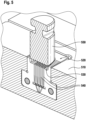
Fig. 5 is a cross-sectional depiction of amoldbar 510 withmold insert 520 defining in particular apre-base cavity 530 and of apunching tool 550 realized as a punching stamp that is arranged for being immersed into thepre-base cavity 530 once it is filled with molten plastic material in order to push the molten plastic into thefine filament cavities 540. In the shown embodiment, thepunching tool 550 has essentially the same shape as the pre-base cavity so that thepunching tool 550 extends over allfilament cavities 540. It is noted that for sake of presentability, the venting cavity at the end of the filament cavities is shown with a dramatically increased depth. As was discussed, the depth of the venting cavity is in the range of a few micrometers. - In some embodiments, the punching tool is realized by one of the mold halves and the mold halves are then moved relatively towards each other to generate the needed pressure that drives the molten plastic into the at least one filament cavity. In some embodiments, the punching tool is an element that can be independently moved with respect to the mold halves as was described.
- In some embodiments, the pressure at which the molten plastic material is injected into the mold cavity is chosen such that the at least one filament cavity is essentially not filled, i.e. the injection pressure is chosen so low that the molten plastic material is not pushed into the filament cavities. In other words, if a pressure value P is needed to at least partially fill the filament cavity, then the pressure with which the plastic is injected into the base cavity is chosen such that the pressure in the molten plastic material at the location of the filament cavity is below this pressure P. This assures that the molten plastic material does not already solidify in the thin filament cavities prior to filling the whole filament cavity under the pressure of the punching tool. While the molten plastic may form a thin skin of relatively cool plastic material extending over the filament cavities prior to immersing the punching tool into the pre-base cavity, the high pressure exerted by the punching tool will push the still liquid plastic material through the cooled skin into the filament cavities. Because of the sudden high pressure, the molten plastic material is filling the thin filament cavity up to the small blind-hole end. In some embodiments, the at least one filament cavity has a height in the range of between 3.0 mm and 20.0 mm, in particular of between 8.0 mm and 12.0 mm, and has a blind-hole end diameter in the range of between 5 µm and 40 µm, in particular of between 8 µm and 20 µm.
- While here the term "blind-hole end" of the filament cavity is used, this shall not exclude that the filament cavity has a venting structure for guiding air out of the filament cavity. Such a venting structure may in particular have a venting cavity that is in air-conducting connection with the blind-hole end of the filament cavity. The thickness of the venting cavity at least at the location where the venting cavity is in air-conducting connection with the blind-hole end of the filament cavity is in the range of between 2 µm and 10 µm, in particular in the range of between 3 µm and 7 µm, and further in particular of around 5 µm.
- As was mentioned before, the herein described method to manufacture a unitary brush head may be used to manufacture unitary brush heads suitable for replacement brushes for electric toothbrushes. In particular, a unitary brush head having a circular or elliptical/oval shape may be made and may then be connected with a drive section comprising a coupling portion. The filaments may be arranged on vertices of a rectangular lattice as was described before or the filaments may be arranged in rings. For the latter arrangement, insert plates may be provided having a circular or elliptical/oval shape (in particular, e.g. two semi-circular insert plates may form together a circular insert plate).
-
Fig. 6A is a top view onto a portion of anexample mold bar 900 comprising amold insert 910 that comprises several essentially ring-like (here: ellipsoidal)insert plates filament cavities 930 so that the filaments are finally essentially arranged on rings.Fig. 6B is a perspective view onto a singleexample insert ring 950 that may be used in amold insert 910 as shown inFig. 6A . Theinsert ring 950 comprisespartial filament cavities outer face side 970 of the insert ring and on theinner face side 971 of theinsert ring 950. As is shown inFig. 6A , thepartial filament cavities Fig. 6A , the symmetrically arranged partial filament cavities of the stacked ring-like insert plates automatically align due to the ellipsoidal form of the insert plates. In case of circular insert plates, the insert plates may have at least one cooperating groove and projection pair for aligning the insert plates. Again, whileFigs. 6A and 6B show insert plates having a structured outer and a structured inner side face, in other embodiments, only one of the side faces may be structured to form filament cavities. Essentially the same applies that was above said in connection with the planar insert plates. - The dimensions and values disclosed herein are not to be understood as being strictly limited to the exact numerical values recited. Instead, unless otherwise specified, each such dimension is intended to mean both the recited value and a functionally equivalent range surrounding that value. For example, a dimension disclosed as "40 mm" is intended to mean "about 40 mm."
Claims (13)
- A method of manufacturing a mold insert (400) for injection molding, in particular injection compression molding, of a unitary brush head (2) having a base (3) and filaments (4) extending therefrom comprising the steps of:- providing at least a first insert plate (410) and a second insert plate (4301) that each have at least one front face (801);- forming a portion of at least one filament cavity (810) into at least one of the front faces (801) of the first or second insert plate (410; 4301) such that the filament cavity (810) is open at a top surface (808) of the insert plate (410) but does not extend through to a bottom surface (809) of the insert plate (800);- forming a venting cavity (890) into the same front face (801) into which the filament cavity (810) is formed, where the venting cavity (890) is formed with a depth in the range of between 1 µm and 20 µm, in particular of between 2 µm and 10 µm, such that the venting cavity (890) is in air conducting connection with the blind-hole end (813) of the filament cavity (810); and- bringing the front faces of the first and second insert plates (410: 4301) into close abutment so that at least one filament cavity (431) is formed.
- The method in accordance with claim 1, wherein the step of forming the portion of the at least one filament cavity (810) or the venting cavity (890) comprises using at least one of precise electrochemical machining (PECM) technology or laser ablation technology, in particular of ultra-short pulsed laser ablation technology.
- The method in accordance with claim 1 or claim 2, wherein the step of forming the portion of the at least one filament cavity (810) comprises forming the blind hole end (813) of the filament cavity (810) with a diameter in the range of between 5 µm to 40 µm, in particular in the range of between 5 µm and 20 µm, and wherein the depth of the venting cavity (890) is smaller than the diameter of the filament cavity (810) at its blind-hole end (813).
- The method in accordance with any one of claims 1 to 3, wherein the step of providing the at least first and second insert plates (410; 4301) comprises providing more than two insert plates (410; 4301; 420) each having at least one front face, in particular wherein the at least three insert plates include a first insert end plate (410), a second insert end plate (420), and at least one center insert plate (4301).
- The method in accordance with any one of claims 1 to 4, wherein the step of providing the at least first and second insert plates (920, 921) comprises providing at least one of the insert plates (921) in an essentially hollow cylinder-like or hollow frustum of cone-like shape.
- A mold insert (400) defining at least one filament cavity (431) and comprising a stack of at least a first insert plate (410) and a second insert plate (4301), whereinthe first plate (410) has a front face (801) that closely abuts a front face (801) of the second insert plate (4301);at least a portion of the at least one filament cavity (810) is provided in at least one of the front faces (801) of the first insert plate (410) or second insert plate (4301) such that the filament cavity (431) is open at a top surface of the mold insert but does not extend to a bottom surface of the mold insert (400);a venting cavity (890) is provided in the same front face (801) of the insert plate (410; 4301) in which the portion of the at least one filament cavity (810) is provided, which venting cavity (890) is in air-conducting connection with the blind-hole end (813) of the filament cavity (810);the venting cavity (890) has a depth in a direction essentially perpendicular to the front face of the respective first or second insert plate (410; 4301) in which the venting cavity (890) is provided that is the in the range of between 1 µm and 20 µm, in particular of between 2 µm and 10 µm;wherein several filament cavities (810) are provided in the same front face (810) and the venting cavity (890) is in air-conducting connection with each of the blind-hole ends (813) of the filament cavities (810); andwherein the venting cavity (890) is an essentially planar structure having a width in a range of between 500 micrometers to 50 millimeter and at least one spacer element (891) is provided within the planar structure, which at least one spacer element (891) projects from a bottom of the venting cavity (890) and has a height that coincides with the depth of the venting cavity (890).
- The mold insert in accordance with claim 6, comprising at least three insert plates (410, 4301, 420), where two of the insert plates are a first end plate (410) and a second end plate (420) that each have one front face and at least one insert plate is a center insert plate (4301) that has two front faces and each of these front faces is in close abutment with one of the front faces of the first and second insert end plates (410; 420).
- The mold insert in accordance with claim 7, wherein the at least one center insert plate (4301) has a thickness in the range of between 0.5 mm and 5.0 mm, in particular in the range of between 0.7 mm and 2.0 mm.
- The mold insert in accordance with any of the claims 6 to 8, wherein the at least one filament cavity (810) has a diameter at the top side (808) of the insert (400) in in the range of between 0.3 mm to 0.8 mm, in particular in the range of between 0.4 mm and 0.6 mm, further in particular wherein the filament cavity (810) tapers towards its blind-hole end (813) with a deforming angle in the range of between 0.1 degrees and 1.0 degrees over at least about half the length of the filament cavity (810).
- The mold insert in accordance with any of the claims 6 to 9, wherein at least one of the insert plates (921) has an essentially hollow cylinder-like or hollow frustum of cone-like shape.
- The mold insert in accordance with any one of claims 6 to 10, wherein a depression (820) is provided in a top surface (808) of the mold insert (400), which depression defines at least a portion of a base (3) of a unitary brush head (2) having a base (3) and at least one filament (4) that extends from the base.
- An injection molding machine, in particular an injection compression molding machine comprising a mold insert (400) in accordance with any one of claims 6 to 11.
- The injection molding machine in accordance with claim 12, wherein the injection molding machine is arranged to push the insert plates (410, 420, 430) of the mold insert (400) together with a compression force inhibiting that the insert plates (410, 420, 430) open under the applied pressure during the injection process.
Priority Applications (5)
| Application Number | Priority Date | Filing Date | Title |
|---|---|---|---|
| CN201880063104.3A CN111182815B (en) | 2017-09-28 | 2018-09-05 | Mold insert and method of making a mold insert |
| PCT/US2018/049439 WO2019067171A1 (en) | 2017-09-28 | 2018-09-05 | MOLD INSERT AND METHOD FOR MANUFACTURING MOLD INSERT |
| US16/131,823 US11425992B2 (en) | 2017-09-28 | 2018-09-14 | Mold insert and method of making a mold insert |
| US17/547,337 US11666136B2 (en) | 2017-09-28 | 2021-12-10 | Mold insert and method of making a mold insert |
| US18/140,922 US12011082B2 (en) | 2017-09-28 | 2023-04-28 | Mold insert and method of making a mold insert |
Applications Claiming Priority (1)
| Application Number | Priority Date | Filing Date | Title |
|---|---|---|---|
| EP17193708.9A EP3461367B1 (en) | 2017-09-28 | 2017-09-28 | Method of making a unitary brush head and unitary toothbrush head |
Publications (2)
| Publication Number | Publication Date |
|---|---|
| EP3461368A1 EP3461368A1 (en) | 2019-04-03 |
| EP3461368B1 true EP3461368B1 (en) | 2024-12-11 |
Family
ID=59974317
Family Applications (2)
| Application Number | Title | Priority Date | Filing Date |
|---|---|---|---|
| EP17193708.9A Active EP3461367B1 (en) | 2017-09-28 | 2017-09-28 | Method of making a unitary brush head and unitary toothbrush head |
| EP18178353.1A Active EP3461368B1 (en) | 2017-09-28 | 2018-06-18 | Mold insert and method of making a mold insert |
Family Applications Before (1)
| Application Number | Title | Priority Date | Filing Date |
|---|---|---|---|
| EP17193708.9A Active EP3461367B1 (en) | 2017-09-28 | 2017-09-28 | Method of making a unitary brush head and unitary toothbrush head |
Country Status (5)
| Country | Link |
|---|---|
| US (5) | US11425992B2 (en) |
| EP (2) | EP3461367B1 (en) |
| CN (3) | CN111182815B (en) |
| BR (1) | BR112020005705B1 (en) |
| WO (2) | WO2019067171A1 (en) |
Families Citing this family (11)
| Publication number | Priority date | Publication date | Assignee | Title |
|---|---|---|---|---|
| EP3461367B1 (en) | 2017-09-28 | 2020-04-22 | The Procter & Gamble Company | Method of making a unitary brush head and unitary toothbrush head |
| EP4151122A1 (en) * | 2018-10-22 | 2023-03-22 | Zahoransky AG | Method of forming bristle bundles and brush |
| JP7652528B2 (en) | 2018-12-28 | 2025-03-27 | 小林製薬株式会社 | Interdental Cleaning Tools |
| JP2020103851A (en) | 2018-12-28 | 2020-07-09 | 小林製薬株式会社 | Interdental cleaning tool |
| JP7417353B2 (en) * | 2018-12-28 | 2024-01-18 | 小林製薬株式会社 | Manufacturing method for interdental cleaning tools |
| USD895973S1 (en) | 2019-03-22 | 2020-09-15 | Colgate-Palmolive Company | Oral care implement |
| US20210323205A1 (en) * | 2020-04-21 | 2021-10-21 | Elc Management Llc | Cosmetic lip applicator |
| CN111688127A (en) * | 2020-07-08 | 2020-09-22 | 成都工业学院 | Injection molding mold of microneedle chip and manufacturing method thereof |
| CN112060484B (en) * | 2020-08-21 | 2024-12-13 | 慈溪市精诚模具有限公司 | A molding die and process for oral cleaning brush head |
| USD1078283S1 (en) * | 2022-09-16 | 2025-06-10 | Gruber, Llc | Tooth cleaning device |
| WO2024142677A1 (en) * | 2022-12-27 | 2024-07-04 | ライオン株式会社 | Toothbrush |
Family Cites Families (38)
| Publication number | Priority date | Publication date | Assignee | Title |
|---|---|---|---|---|
| CA670147A (en) | 1963-09-10 | Smyth Donald | Tufted brush with moulded bristles and method of manufacturing same | |
| GB868957A (en) | 1959-01-23 | 1961-05-25 | John Denman Dean | Improvements in methods and an apparatus for the manufacture of brushes and the like |
| US3173177A (en) | 1962-04-17 | 1965-03-16 | Valden Company | Apparatus for forming brushes and the like |
| SE310646B (en) * | 1964-10-30 | 1969-05-12 | A Poppelman | |
| US3357058A (en) * | 1966-10-31 | 1967-12-12 | Gronemeyer Erich W | Apparatus for injection molding a bristled product |
| US3467990A (en) | 1967-02-16 | 1969-09-23 | Louis F Kutik | Mold apparatus for bristled products |
| US3847532A (en) | 1972-03-22 | 1974-11-12 | E Bischoff | Apparatus for fabricating brushes having molded ends |
| US3996330A (en) * | 1974-09-20 | 1976-12-07 | Vistron Corporation | Method of making a molded brush back |
| DE2728672A1 (en) | 1977-06-25 | 1979-01-11 | Hairmatic Ag | Tooth brush with integrally moulded head and bristles - has bristles with either pointed or rounded ends and tapered shaft with socket for drive mechanism |
| US4422986A (en) | 1981-09-23 | 1983-12-27 | Cole William E | Method and apparatus for infection molding brushes |
| GB8714036D0 (en) | 1987-06-16 | 1987-07-22 | Cole R D | Integrally moulded brushes |
| GB2255901B (en) * | 1991-05-21 | 1995-07-19 | Appealing Appliances Co Ltd | Electric toothbrush holder |
| IL112207A (en) * | 1994-12-30 | 1999-03-12 | Eureka Technologies Innovation | Accessory device for toothbrushes |
| US5636405A (en) | 1995-05-19 | 1997-06-10 | Stone; Cheryl F. | Finger toothbrush/handle-less toothbrush |
| US5926900A (en) | 1997-06-16 | 1999-07-27 | Chesebrough-Pond's Usa Co. | Unitarily molded toothbrush |
| DE19925568A1 (en) | 1999-06-04 | 2000-12-07 | Joerg Hofmann | Brush head for a toothbrush has bristles and shaft molded as an integral unit |
| DE10033256A1 (en) * | 2000-07-10 | 2002-01-24 | Coronet Werke Gmbh | Method and device for producing bristle goods and bristle goods |
| DE10201635A1 (en) | 2002-01-17 | 2003-07-31 | Coronet Werke Gmbh | Method and device for producing bristles |
| DE10221869A1 (en) * | 2002-05-15 | 2003-11-27 | Coronet Werke Gmbh | Brush bristle molding method involves forcing bristle material under pressure through a bristle carrier material into individual cavities |
| US20030221273A1 (en) * | 2002-05-28 | 2003-12-04 | Phillip Mark | Method and apparatus for injection molding a plastic monolith |
| JP2006034497A (en) | 2004-07-26 | 2006-02-09 | Toto Kizai Kk | Cosmetic applicator and method of manufacturing cosmetic applicator |
| KR100637380B1 (en) | 2004-12-08 | 2006-10-23 | 권영준 | Method for manufacturing toothbrush with needle-shaped hair and toothbrush manufactured thereby |
| JP2010502267A (en) * | 2006-08-28 | 2010-01-28 | エージェンシー・フォー・サイエンス・テクノロジー・アンド・リサーチ | Microneedle and method for producing microneedle |
| US20090007357A1 (en) | 2007-05-07 | 2009-01-08 | The Gillette Company | Oral Hygiene Implements |
| FR2917276B1 (en) * | 2007-06-15 | 2012-07-27 | Cinqpats | DEVICE AND PACKAGING FOR PRECISION BRUSHING AND GUNNING, AND METHOD AND TOOLING FOR OBTAINING |
| FI122995B (en) | 2008-08-12 | 2012-09-28 | Stora Enso Oyj | Molding system and process for the manufacture of a vessel |
| EP2184032A1 (en) * | 2008-11-05 | 2010-05-12 | Braun Gmbh | Electric toothbrush and brush head therefor |
| JP2012523270A (en) * | 2009-04-10 | 2012-10-04 | スリーエム イノベイティブ プロパティズ カンパニー | Method for producing hollow microneedle array, product derived therefrom and use thereof |
| FR2968907B1 (en) * | 2010-12-21 | 2013-09-13 | Oreal | APPLICATION AND / OR SEPARATION DEVICE HAVING HIGH DENSITY OF DRESSED ELEMENTS FROM A SUPPORT |
| EP2534973B1 (en) * | 2011-06-15 | 2015-04-08 | Braun GmbH | Method and tool for producing a brush head |
| US9210995B2 (en) | 2012-09-25 | 2015-12-15 | O'nano Oral Solutions, Inc. | Toothbrush |
| CN203776358U (en) * | 2013-05-28 | 2014-08-20 | 吴永 | Bristle and toothbrush |
| ITBO20130443A1 (en) | 2013-08-06 | 2015-02-07 | Daniele Trasforini | TOOL FOR MECHANICAL PROCESSING, PROCEDURE AND EQUIPMENT FOR THE CREATION OF A TOOL FOR MECHANICAL PROCESSING. |
| US10245720B2 (en) * | 2014-09-12 | 2019-04-02 | Chris Ptak | Elastic vibrating appliance handle |
| US10010167B2 (en) * | 2015-08-28 | 2018-07-03 | Enayatullah MOTAHEDY | Motorized cleaning system for a brush |
| EP3138437B1 (en) | 2015-09-03 | 2021-11-10 | Braun GmbH | Method of manufacturing a brush |
| CN108601442A (en) * | 2015-11-04 | 2018-09-28 | 特里沙控股公司 | Body care brush with injected bristles |
| EP3461367B1 (en) | 2017-09-28 | 2020-04-22 | The Procter & Gamble Company | Method of making a unitary brush head and unitary toothbrush head |
-
2017
- 2017-09-28 EP EP17193708.9A patent/EP3461367B1/en active Active
-
2018
- 2018-06-18 EP EP18178353.1A patent/EP3461368B1/en active Active
- 2018-09-05 WO PCT/US2018/049439 patent/WO2019067171A1/en not_active Ceased
- 2018-09-05 CN CN201880063104.3A patent/CN111182815B/en active Active
- 2018-09-14 US US16/131,823 patent/US11425992B2/en active Active
- 2018-09-14 US US16/131,493 patent/US10980336B2/en active Active
- 2018-09-19 BR BR112020005705-3A patent/BR112020005705B1/en active IP Right Grant
- 2018-09-19 CN CN202210697805.0A patent/CN115227025B/en active Active
- 2018-09-19 WO PCT/US2018/051644 patent/WO2019067275A1/en not_active Ceased
- 2018-09-19 CN CN201880063159.4A patent/CN111163662B/en active Active
-
2021
- 2021-03-05 US US17/193,145 patent/US11819118B2/en active Active
- 2021-12-10 US US17/547,337 patent/US11666136B2/en active Active
-
2023
- 2023-04-28 US US18/140,922 patent/US12011082B2/en active Active
Also Published As
| Publication number | Publication date |
|---|---|
| US20190381710A1 (en) | 2019-12-19 |
| US11819118B2 (en) | 2023-11-21 |
| US12011082B2 (en) | 2024-06-18 |
| BR112020005705B1 (en) | 2024-01-30 |
| US20220095777A1 (en) | 2022-03-31 |
| CN111182815A (en) | 2020-05-19 |
| US11666136B2 (en) | 2023-06-06 |
| BR112020005705A2 (en) | 2020-10-20 |
| CN115227025A (en) | 2022-10-25 |
| US11425992B2 (en) | 2022-08-30 |
| WO2019067171A1 (en) | 2019-04-04 |
| EP3461367B1 (en) | 2020-04-22 |
| EP3461368A1 (en) | 2019-04-03 |
| US20190090623A1 (en) | 2019-03-28 |
| CN111163662A (en) | 2020-05-15 |
| CN111182815B (en) | 2024-06-11 |
| US10980336B2 (en) | 2021-04-20 |
| CN111163662B (en) | 2022-09-13 |
| EP3461367A1 (en) | 2019-04-03 |
| CN115227025B (en) | 2024-11-12 |
| US20230255343A1 (en) | 2023-08-17 |
| US20210204683A1 (en) | 2021-07-08 |
| WO2019067275A1 (en) | 2019-04-04 |
Similar Documents
| Publication | Publication Date | Title |
|---|---|---|
| US12011082B2 (en) | Mold insert and method of making a mold insert | |
| CN101031221B (en) | Method for manufacturing cosmetic hair brush | |
| US7644466B2 (en) | Bristles, method and device for production thereof and brushes | |
| EP2085195B1 (en) | Trimmer comb, hair trimmer comprising a trimmer comb and method of manufacturing a trimmer comb | |
| CN111451503A (en) | S L M additive manufacturing fine part printing support adding method and removing method | |
| JPH0470040B2 (en) | ||
| JP2008161874A (en) | Extrusion die manufacturing method and electric discharge machining electrode used therefor | |
| DE69100020T2 (en) | ELECTRODE HOLDER FOR ELECTROEROSIVE MACHINING. | |
| JP4333236B2 (en) | Method of manufacturing mold for manufacturing liquid jet head and material block thereof | |
| EP0075051B1 (en) | Apparatus for making at least part of a miniature make-up brush | |
| JP3181065B2 (en) | Dam bar cut punch guide | |
| JP3212058B2 (en) | Mold for forming nozzle plate and method of manufacturing the same | |
| JP3127833U (en) | Injection mold | |
| DE102011108753A1 (en) | Indexable insert has actuator that is provided for metrological detection of vibrations of cutting edge | |
| JPH11245232A (en) | Molding mold and method of manufacturing inkjet printer head molding mold | |
| HK1107235B (en) | Process for making a cosmetic brush | |
| KR20100133119A (en) | Gas or liquid discharge block and its manufacturing method | |
| JPH0655363A (en) | Electric discharge machining electrode and this electrode driving control method | |
| JP2000190354A (en) | injection molding | |
| JPH10128806A (en) | Nozzle plate, manufacturing method and apparatus therefor |
Legal Events
| Date | Code | Title | Description |
|---|---|---|---|
| PUAI | Public reference made under article 153(3) epc to a published international application that has entered the european phase |
Free format text: ORIGINAL CODE: 0009012 |
|
| STAA | Information on the status of an ep patent application or granted ep patent |
Free format text: STATUS: THE APPLICATION HAS BEEN PUBLISHED |
|
| AK | Designated contracting states |
Kind code of ref document: A1 Designated state(s): AL AT BE BG CH CY CZ DE DK EE ES FI FR GB GR HR HU IE IS IT LI LT LU LV MC MK MT NL NO PL PT RO RS SE SI SK SM TR |
|
| AX | Request for extension of the european patent |
Extension state: BA ME |
|
| STAA | Information on the status of an ep patent application or granted ep patent |
Free format text: STATUS: REQUEST FOR EXAMINATION WAS MADE |
|
| 17P | Request for examination filed |
Effective date: 20190910 |
|
| RBV | Designated contracting states (corrected) |
Designated state(s): AL AT BE BG CH CY CZ DE DK EE ES FI FR GB GR HR HU IE IS IT LI LT LU LV MC MK MT NL NO PL PT RO RS SE SI SK SM TR |
|
| STAA | Information on the status of an ep patent application or granted ep patent |
Free format text: STATUS: EXAMINATION IS IN PROGRESS |
|
| 17Q | First examination report despatched |
Effective date: 20221123 |
|
| P01 | Opt-out of the competence of the unified patent court (upc) registered |
Effective date: 20230429 |
|
| GRAP | Despatch of communication of intention to grant a patent |
Free format text: ORIGINAL CODE: EPIDOSNIGR1 |
|
| STAA | Information on the status of an ep patent application or granted ep patent |
Free format text: STATUS: GRANT OF PATENT IS INTENDED |
|
| RIC1 | Information provided on ipc code assigned before grant |
Ipc: B29C 45/56 20060101ALI20240702BHEP Ipc: B29C 45/34 20060101ALI20240702BHEP Ipc: B29C 45/26 20060101ALI20240702BHEP Ipc: B29C 45/14 20060101ALI20240702BHEP Ipc: B29C 43/00 20060101ALI20240702BHEP Ipc: B29C 33/30 20060101ALI20240702BHEP Ipc: A46B 9/04 20060101ALI20240702BHEP Ipc: A46D 1/00 20060101ALI20240702BHEP Ipc: A46B 3/12 20060101ALI20240702BHEP Ipc: A46B 3/04 20060101ALI20240702BHEP Ipc: A46B 3/00 20060101ALI20240702BHEP Ipc: A46B 1/00 20060101AFI20240702BHEP |
|
| INTG | Intention to grant announced |
Effective date: 20240718 |
|
| GRAS | Grant fee paid |
Free format text: ORIGINAL CODE: EPIDOSNIGR3 |
|
| GRAA | (expected) grant |
Free format text: ORIGINAL CODE: 0009210 |
|
| STAA | Information on the status of an ep patent application or granted ep patent |
Free format text: STATUS: THE PATENT HAS BEEN GRANTED |
|
| AK | Designated contracting states |
Kind code of ref document: B1 Designated state(s): AL AT BE BG CH CY CZ DE DK EE ES FI FR GB GR HR HU IE IS IT LI LT LU LV MC MK MT NL NO PL PT RO RS SE SI SK SM TR |
|
| REG | Reference to a national code |
Ref country code: GB Ref legal event code: FG4D |
|
| REG | Reference to a national code |
Ref country code: CH Ref legal event code: EP |
|
| REG | Reference to a national code |
Ref country code: DE Ref legal event code: R096 Ref document number: 602018077450 Country of ref document: DE |
|
| REG | Reference to a national code |
Ref country code: IE Ref legal event code: FG4D |
|
| REG | Reference to a national code |
Ref country code: LT Ref legal event code: MG9D |
|
| PG25 | Lapsed in a contracting state [announced via postgrant information from national office to epo] |
Ref country code: HR Free format text: LAPSE BECAUSE OF FAILURE TO SUBMIT A TRANSLATION OF THE DESCRIPTION OR TO PAY THE FEE WITHIN THE PRESCRIBED TIME-LIMIT Effective date: 20241211 |
|
| PG25 | Lapsed in a contracting state [announced via postgrant information from national office to epo] |
Ref country code: FI Free format text: LAPSE BECAUSE OF FAILURE TO SUBMIT A TRANSLATION OF THE DESCRIPTION OR TO PAY THE FEE WITHIN THE PRESCRIBED TIME-LIMIT Effective date: 20241211 |
|
| PG25 | Lapsed in a contracting state [announced via postgrant information from national office to epo] |
Ref country code: BG Free format text: LAPSE BECAUSE OF FAILURE TO SUBMIT A TRANSLATION OF THE DESCRIPTION OR TO PAY THE FEE WITHIN THE PRESCRIBED TIME-LIMIT Effective date: 20241211 |
|
| REG | Reference to a national code |
Ref country code: NL Ref legal event code: MP Effective date: 20241211 |
|
| PG25 | Lapsed in a contracting state [announced via postgrant information from national office to epo] |
Ref country code: ES Free format text: LAPSE BECAUSE OF FAILURE TO SUBMIT A TRANSLATION OF THE DESCRIPTION OR TO PAY THE FEE WITHIN THE PRESCRIBED TIME-LIMIT Effective date: 20241211 |
|
| PG25 | Lapsed in a contracting state [announced via postgrant information from national office to epo] |
Ref country code: NO Free format text: LAPSE BECAUSE OF FAILURE TO SUBMIT A TRANSLATION OF THE DESCRIPTION OR TO PAY THE FEE WITHIN THE PRESCRIBED TIME-LIMIT Effective date: 20250311 |
|
| PG25 | Lapsed in a contracting state [announced via postgrant information from national office to epo] |
Ref country code: LV Free format text: LAPSE BECAUSE OF FAILURE TO SUBMIT A TRANSLATION OF THE DESCRIPTION OR TO PAY THE FEE WITHIN THE PRESCRIBED TIME-LIMIT Effective date: 20241211 Ref country code: GR Free format text: LAPSE BECAUSE OF FAILURE TO SUBMIT A TRANSLATION OF THE DESCRIPTION OR TO PAY THE FEE WITHIN THE PRESCRIBED TIME-LIMIT Effective date: 20250312 |
|
| PG25 | Lapsed in a contracting state [announced via postgrant information from national office to epo] |
Ref country code: RS Free format text: LAPSE BECAUSE OF FAILURE TO SUBMIT A TRANSLATION OF THE DESCRIPTION OR TO PAY THE FEE WITHIN THE PRESCRIBED TIME-LIMIT Effective date: 20250311 |
|
| PG25 | Lapsed in a contracting state [announced via postgrant information from national office to epo] |
Ref country code: NL Free format text: LAPSE BECAUSE OF FAILURE TO SUBMIT A TRANSLATION OF THE DESCRIPTION OR TO PAY THE FEE WITHIN THE PRESCRIBED TIME-LIMIT Effective date: 20241211 |
|
| REG | Reference to a national code |
Ref country code: AT Ref legal event code: MK05 Ref document number: 1749642 Country of ref document: AT Kind code of ref document: T Effective date: 20241211 |
|
| PG25 | Lapsed in a contracting state [announced via postgrant information from national office to epo] |
Ref country code: SM Free format text: LAPSE BECAUSE OF FAILURE TO SUBMIT A TRANSLATION OF THE DESCRIPTION OR TO PAY THE FEE WITHIN THE PRESCRIBED TIME-LIMIT Effective date: 20241211 |
|
| PG25 | Lapsed in a contracting state [announced via postgrant information from national office to epo] |
Ref country code: PL Free format text: LAPSE BECAUSE OF FAILURE TO SUBMIT A TRANSLATION OF THE DESCRIPTION OR TO PAY THE FEE WITHIN THE PRESCRIBED TIME-LIMIT Effective date: 20241211 |
|
| PGFP | Annual fee paid to national office [announced via postgrant information from national office to epo] |
Ref country code: DE Payment date: 20250429 Year of fee payment: 8 |
|
| PG25 | Lapsed in a contracting state [announced via postgrant information from national office to epo] |
Ref country code: IS Free format text: LAPSE BECAUSE OF FAILURE TO SUBMIT A TRANSLATION OF THE DESCRIPTION OR TO PAY THE FEE WITHIN THE PRESCRIBED TIME-LIMIT Effective date: 20250411 |
|
| PGFP | Annual fee paid to national office [announced via postgrant information from national office to epo] |
Ref country code: BE Payment date: 20250516 Year of fee payment: 8 Ref country code: IT Payment date: 20250522 Year of fee payment: 8 |
|
| PG25 | Lapsed in a contracting state [announced via postgrant information from national office to epo] |
Ref country code: PT Free format text: LAPSE BECAUSE OF FAILURE TO SUBMIT A TRANSLATION OF THE DESCRIPTION OR TO PAY THE FEE WITHIN THE PRESCRIBED TIME-LIMIT Effective date: 20250411 |
|
| PG25 | Lapsed in a contracting state [announced via postgrant information from national office to epo] |
Ref country code: EE Free format text: LAPSE BECAUSE OF FAILURE TO SUBMIT A TRANSLATION OF THE DESCRIPTION OR TO PAY THE FEE WITHIN THE PRESCRIBED TIME-LIMIT Effective date: 20241211 |
|
| PG25 | Lapsed in a contracting state [announced via postgrant information from national office to epo] |
Ref country code: AT Free format text: LAPSE BECAUSE OF FAILURE TO SUBMIT A TRANSLATION OF THE DESCRIPTION OR TO PAY THE FEE WITHIN THE PRESCRIBED TIME-LIMIT Effective date: 20241211 Ref country code: RO Free format text: LAPSE BECAUSE OF FAILURE TO SUBMIT A TRANSLATION OF THE DESCRIPTION OR TO PAY THE FEE WITHIN THE PRESCRIBED TIME-LIMIT Effective date: 20241211 |
|
| PG25 | Lapsed in a contracting state [announced via postgrant information from national office to epo] |
Ref country code: SK Free format text: LAPSE BECAUSE OF FAILURE TO SUBMIT A TRANSLATION OF THE DESCRIPTION OR TO PAY THE FEE WITHIN THE PRESCRIBED TIME-LIMIT Effective date: 20241211 |
|
| PG25 | Lapsed in a contracting state [announced via postgrant information from national office to epo] |
Ref country code: CZ Free format text: LAPSE BECAUSE OF FAILURE TO SUBMIT A TRANSLATION OF THE DESCRIPTION OR TO PAY THE FEE WITHIN THE PRESCRIBED TIME-LIMIT Effective date: 20241211 |
|
| PG25 | Lapsed in a contracting state [announced via postgrant information from national office to epo] |
Ref country code: SE Free format text: LAPSE BECAUSE OF FAILURE TO SUBMIT A TRANSLATION OF THE DESCRIPTION OR TO PAY THE FEE WITHIN THE PRESCRIBED TIME-LIMIT Effective date: 20241211 |
|
| REG | Reference to a national code |
Ref country code: DE Ref legal event code: R097 Ref document number: 602018077450 Country of ref document: DE |
|
| PG25 | Lapsed in a contracting state [announced via postgrant information from national office to epo] |
Ref country code: DK Free format text: LAPSE BECAUSE OF FAILURE TO SUBMIT A TRANSLATION OF THE DESCRIPTION OR TO PAY THE FEE WITHIN THE PRESCRIBED TIME-LIMIT Effective date: 20241211 |
|
| PLBE | No opposition filed within time limit |
Free format text: ORIGINAL CODE: 0009261 |
|
| STAA | Information on the status of an ep patent application or granted ep patent |
Free format text: STATUS: NO OPPOSITION FILED WITHIN TIME LIMIT |
|
| PGFP | Annual fee paid to national office [announced via postgrant information from national office to epo] |
Ref country code: CH Payment date: 20250701 Year of fee payment: 8 |
|
| 26N | No opposition filed |
Effective date: 20250912 |
|
| PG25 | Lapsed in a contracting state [announced via postgrant information from national office to epo] |
Ref country code: MC Free format text: LAPSE BECAUSE OF FAILURE TO SUBMIT A TRANSLATION OF THE DESCRIPTION OR TO PAY THE FEE WITHIN THE PRESCRIBED TIME-LIMIT Effective date: 20241211 |
|
| PG25 | Lapsed in a contracting state [announced via postgrant information from national office to epo] |
Ref country code: LU Free format text: LAPSE BECAUSE OF NON-PAYMENT OF DUE FEES Effective date: 20250618 |
|
| GBPC | Gb: european patent ceased through non-payment of renewal fee |
Effective date: 20250618 |
|
| PG25 | Lapsed in a contracting state [announced via postgrant information from national office to epo] |
Ref country code: GB Free format text: LAPSE BECAUSE OF NON-PAYMENT OF DUE FEES Effective date: 20250618 |
|
| PG25 | Lapsed in a contracting state [announced via postgrant information from national office to epo] |
Ref country code: IE Free format text: LAPSE BECAUSE OF NON-PAYMENT OF DUE FEES Effective date: 20250618 |
|
| PG25 | Lapsed in a contracting state [announced via postgrant information from national office to epo] |
Ref country code: FR Free format text: LAPSE BECAUSE OF NON-PAYMENT OF DUE FEES Effective date: 20250630 |