EP3461278B1 - Metal-to-metal well equipment seal - Google Patents
Metal-to-metal well equipment seal Download PDFInfo
- Publication number
- EP3461278B1 EP3461278B1 EP17800289.5A EP17800289A EP3461278B1 EP 3461278 B1 EP3461278 B1 EP 3461278B1 EP 17800289 A EP17800289 A EP 17800289A EP 3461278 B1 EP3461278 B1 EP 3461278B1
- Authority
- EP
- European Patent Office
- Prior art keywords
- equipment
- seal
- piece
- metallic sealing
- sealing surface
- Prior art date
- Legal status (The legal status is an assumption and is not a legal conclusion. Google has not performed a legal analysis and makes no representation as to the accuracy of the status listed.)
- Active
Links
Images




Classifications
-
- F—MECHANICAL ENGINEERING; LIGHTING; HEATING; WEAPONS; BLASTING
- F16—ENGINEERING ELEMENTS AND UNITS; GENERAL MEASURES FOR PRODUCING AND MAINTAINING EFFECTIVE FUNCTIONING OF MACHINES OR INSTALLATIONS; THERMAL INSULATION IN GENERAL
- F16L—PIPES; JOINTS OR FITTINGS FOR PIPES; SUPPORTS FOR PIPES, CABLES OR PROTECTIVE TUBING; MEANS FOR THERMAL INSULATION IN GENERAL
- F16L23/00—Flanged joints
- F16L23/16—Flanged joints characterised by the sealing means
- F16L23/18—Flanged joints characterised by the sealing means the sealing means being rings
- F16L23/20—Flanged joints characterised by the sealing means the sealing means being rings made exclusively of metal
-
- F—MECHANICAL ENGINEERING; LIGHTING; HEATING; WEAPONS; BLASTING
- F16—ENGINEERING ELEMENTS AND UNITS; GENERAL MEASURES FOR PRODUCING AND MAINTAINING EFFECTIVE FUNCTIONING OF MACHINES OR INSTALLATIONS; THERMAL INSULATION IN GENERAL
- F16L—PIPES; JOINTS OR FITTINGS FOR PIPES; SUPPORTS FOR PIPES, CABLES OR PROTECTIVE TUBING; MEANS FOR THERMAL INSULATION IN GENERAL
- F16L23/00—Flanged joints
- F16L23/16—Flanged joints characterised by the sealing means
- F16L23/167—Flanged joints characterised by the sealing means in connection with the appearance or detection of leaks
-
- G—PHYSICS
- G01—MEASURING; TESTING
- G01M—TESTING STATIC OR DYNAMIC BALANCE OF MACHINES OR STRUCTURES; TESTING OF STRUCTURES OR APPARATUS, NOT OTHERWISE PROVIDED FOR
- G01M3/00—Investigating fluid-tightness of structures
- G01M3/02—Investigating fluid-tightness of structures by using fluid or vacuum
- G01M3/022—Test plugs for closing off the end of a pipe
-
- F—MECHANICAL ENGINEERING; LIGHTING; HEATING; WEAPONS; BLASTING
- F16—ENGINEERING ELEMENTS AND UNITS; GENERAL MEASURES FOR PRODUCING AND MAINTAINING EFFECTIVE FUNCTIONING OF MACHINES OR INSTALLATIONS; THERMAL INSULATION IN GENERAL
- F16L—PIPES; JOINTS OR FITTINGS FOR PIPES; SUPPORTS FOR PIPES, CABLES OR PROTECTIVE TUBING; MEANS FOR THERMAL INSULATION IN GENERAL
- F16L2201/00—Special arrangements for pipe couplings
- F16L2201/30—Detecting leaks
Definitions
- Embodiments usable within the scope of the present disclosure relate, generally, to a pressure-activated metal-to-metal seal for wellheads and other oil & gas equipment.
- the metal-to-metal seals are operable in highly corrosive, high-temperature high-pressure (HPHT) conditions.
- HPHT high pressure, high temperature
- ring seals can be found in US 3,507,506 , EP 2 828 560 , EP 2 619 496 , and CH 499 052 .
- US 3,507,506 describes a pipe joint seal for large size pipes in the form of a tubular member having blunt ends; this is adapted to be disposed in blunt end recesses of aligned flanged pipes connected together under stressed conditions, such as by studs.
- EP 2 828 560 describes a seal assembly for a piping connection, comprising; a first part having at least one projecting rib extending at least partially along an outer circumference thereof, and a second part arranged to be attached to the first part, the second part being provided with at least one recess on an inner surface thereof, which recess is adapted to receive the projecting rib when the first and second parts are connected, and the recess has a larger cross-section area than the cross-section area occupied by the projecting rib within the recess, such that when the first and second parts are connected, they are free to move relative to each other in at least one direction.
- EP 2 619 496 describes a tubular joint comprising: first and second tubular members; a metallic seal ring positioned between the tubular members and having sealing surfaces designed to mate with corresponding sealing surfaces of the tubular members to form a primary seal; an additional seal provided between the tubular members radially outwardly of the primary seal; a fluid channel having an outlet opening in an end surface of the first tubular member radially outwardly of said primary seal and radially inwardly of said additional seal; and annular seal members interposed between the seal ring and the tubular members radially outwardly of the primary seal and radially inwardly of said outlet opening and designed to allow fluid flow past the seal members in a radial direction inwards and to prevent fluid flow past the seal members in a radial direction outwards.
- CH 499 052 describes pipe connections in which the flanges of the pipes to be connected are mechanically tensioned by the forces generated by an external tensioning device and where a metallic ring seal is provided.
- US 3,507,506 describes a pipe joint seal for large size pipes in the form of a tubular member having blunt ends, which is adapted to be disposed in blunt end recesses of aligned flange pipes connected together under stressed conditions. Outer annular marginal grooves near the ends of the tubular members are provided to form noses that concentrate distortion under the stressed conditions at the ends. A stiffening collar is provided integral with the middle section of the tubular member for disposition between adjacent flanges of the pipes.
- Embodiments of the apparatus described herein meet this and other needs.
- the invention provides a system for establishing a metal-to-metal seal joining two bores, as defined in claim 1.
- the present invention relates, generally, to a metal-to-metal seal configuration for use in highly corrosive, HPHT environments but has application in other areas as well.
- This configuration can work in tandem with an existing seal such as a ring-type joint (RTJ) to create a secondary metal-to-metal seal, whereas in existing configurations the secondary seal is usually a standard API ring gasket or single seal combination of metal and elastomer or other easily degraded material.
- RJ ring-type joint
- FIGS. 1A and 1B an overhead view of an exemplar seal 10 is shown, in overhead view in FIG. 1A , as a roughly cylindrical metallic surface surrounding a bore 12 therethrough, and in cross-section along section line B-B in FIG. 1B .
- Seal 10 comprises a total of four sealing surfaces 20, 22, 24, 26, where sealing surfaces 20, 22 form a lip on either side of the seal while sealing surfaces 24, 26 form the shape of a radial (i.e., semi-circular) bulge extending concentrically around the longitudinal axis of the seal.
- the seal also features a groove 28 located interior to the two sealing surfaces 24, 26.
- Groove 28 fulfills two functions: it allows the seal 10 to flex slightly should there be bending, movement, or a change in temperature to the equipment during installation and operation, and it also serves as an extraction groove should the seal 10 become lodged within the equipment.
- seal 10 comprises a first width W1 which is defined by the inner diameter of the bore 12 enclosed by the seal 10, a second width W2 which is defined by the outer diameter of the seal 10 (i.e., the difference between W1 and W2 is a function of seal thickness), and a third width W3 which represents the maximal width at the apex of the two sealing surfaces 24, 26.
- FIGS. 2A-2C a standard flange connection 30 is shown comprising a central bore 32 therethrough.
- FIG. 2A depicts the flange connection 30 in side view
- FIG. 2B depicts a cross-sectional view along section line B-B.
- FIG. 2B depicts a test port 34 located within the flange connection 30 for monitoring the internal pressure of the flange connection 30.
- FIG. 2C depicts a magnified view of section C of FIG. 2B which includes the fluid connection 36 between the test port 34 and the central bore 30.
- Flange connection 30 is also depicted with a negatively angled sealing surface 38 which corresponds to the sealing surface 20 of the seal 10 (both depicted in FIG. 1B ).
- the central bore 32 of flange connection 30 is also depicted having a series of sealing surfaces 38,40 corresponding to stepwise changes in radius, shown as R1, R2, and R3.
- R1, R2, R3 correspond to the W1, W2, W3 widths (i.e., diameters) shown in FIG. 1B . (As every diameter implies a radius and vice versa, they are marked as radii solely for clarity.)
- flange connections 30A, 30B are shown abutted end-to-end in cross-section with their respective bores aligned to form a single bore 32 therethrough.
- Seal 10 is aligned within bore 32 and the sealing surfaces 20, 22, 24, 26 of the seal 10 (depicted in FIG. 1B ) are aligned with the respective sealing surfaces of the flange connections 30A, 30B.
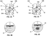
- Test ports 34A and 34B are shown fluidly connected to seal 10, and a test plug 42 may be present during pressure testing.
- flange connections 34A, 34B may comprise a secondary groove 31. This secondary groove 31 can accommodate an RTJ gasket 33 illustrated in FIG. 3D .
- test port 120 can be in communication with the area between RTJ seal 130 and secondary seal 110 in order to determine the efficacy of the secondary seal in isolation.
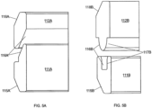
- FIG. 5A a zoomed-in alternative embodiment of the secondary seal 110A as depicted in FIGS. 4A -14C is shown.
- the embodiment depicted in FIG. 5A comprises a lower sealing bowl 111A, an upper sealing bowl 112A, and three sealing areas 115A, 116A, and 118A.
- the fluid pressure within a wellbore is in the upward direction from lower sealing bowl 111A to upper sealing bowl 112A.
- sealing area 115A seals the lower sealing bowl 111A against well equipment (e.g., wellheads, gate valves, Christmas tree valves, choke valves, spools, etc.) while sealing area 118A seals the upper sealing bowl 112A against the well equipment to be connected.
- well equipment e.g., wellheads, gate valves, Christmas tree valves, choke valves, spools, etc.
- Sealing area 116A seals lower sealing bowl 111A against upper sealing bowl 112A.
- the angles of sealing areas 115A, 116A, and 118A ensure that fluid pressure works to further activate the seal after initial connection through torqued studs/nuts as shown in FIGS. 4A-4C .
- secondary seal 110B is depicted which can be used interchangeably and in the same fashion as secondary seal 110A.
- secondary seal 110B comprises a lower sealing bowl 111B and upper sealing bowl 112B, and sealing surfaces 115B and 118B which function substantially similar to 115A and 118A.
- Secondary seal 110B additionally can comprise two intermediate sealing areas 116B and 117B, which further isolate the connected equipment against HPHT fluids.
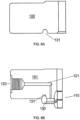
- FIGS. 6A-6B a standard prior art flange connection 100 is shown having a groove 131 for accepting a ring-type joint 130 (shown in FIGS. 4A-4C and 6B ) acting as a primary seal.
- FIG. 6B depicts a modified flange 101 having a testing port 120, which is in fluid communication through an angled aperture 121 into the space between ring-type joint 130 and secondary seal 110 (shown as the alternate embodiment depicted in FIG. 5B ).
- the configuration shown in FIG. 6B allows the secondary seal 110 to be monitored and tested independently of ring-type joint 130.
- FIG. 7 a sectional view of a blind flange 101 having a configuration substantially similar to that shown in FIG. 3B is depicted, with flange 101 more clearly showing the testing port 120 and aperture 121 in relation to the groove 130 and ring-type joint 131, as well as the metal-to-metal seal 110 (shown as the alternate embodiment depicted in FIG. 2B ) comprising lower sealing bowl 111, upper sealing bowl 112, and sealing surfaces 115, 116, 117, and 18.
- the depicted embodiments are capable of maintaining seals at pressures of 34,47MPa (5000psi) in flanged outlets and higher in other end connections (OEC), and temperatures in excess of 250°C; it can be appreciated that all working pressures and configurations described in API specification 6A may be designed for utilizing the central design principles shown herein.
Landscapes
- Engineering & Computer Science (AREA)
- General Engineering & Computer Science (AREA)
- Mechanical Engineering (AREA)
- Physics & Mathematics (AREA)
- General Physics & Mathematics (AREA)
- Gasket Seals (AREA)
Description
- Embodiments usable within the scope of the present disclosure relate, generally, to a pressure-activated metal-to-metal seal for wellheads and other oil & gas equipment. The metal-to-metal seals are operable in highly corrosive, high-temperature high-pressure (HPHT) conditions.
- It is increasingly common in the oil & gas industry for exploration operations to take place in harsh, unfriendly environments and well conditions. Therefore, wellhead equipment must be built to withstand high pressure, high temperature (HPHT) environments, as well as to operate efficiently within conditions that include high levels of sulfides, carbon dioxide, and other corrosive gases or compounds. Such conditions often require a "dual" seal, meaning at least two independent barriers.
- Currently, a common procedure is to coat flanged outlets with a non-corrosive metal, such as Inconel, and accomplish a secondary seal using elastomeric rings or gaskets. However, even these options often see high failure rates. Additionally, they often have limited versatility as the metal must be machined for each joint.
- Examples of ring seals can be found in
US 3,507,506 ,EP 2 828 560 ,EP 2 619 496 , andCH 499 052 -
US 3,507,506 describes a pipe joint seal for large size pipes in the form of a tubular member having blunt ends; this is adapted to be disposed in blunt end recesses of aligned flanged pipes connected together under stressed conditions, such as by studs. -
EP 2 828 560 describes a seal assembly for a piping connection, comprising; a first part having at least one projecting rib extending at least partially along an outer circumference thereof, and a second part arranged to be attached to the first part, the second part being provided with at least one recess on an inner surface thereof, which recess is adapted to receive the projecting rib when the first and second parts are connected, and the recess has a larger cross-section area than the cross-section area occupied by the projecting rib within the recess, such that when the first and second parts are connected, they are free to move relative to each other in at least one direction. -
EP 2 619 496 describes a tubular joint comprising: first and second tubular members; a metallic seal ring positioned between the tubular members and having sealing surfaces designed to mate with corresponding sealing surfaces of the tubular members to form a primary seal; an additional seal provided between the tubular members radially outwardly of the primary seal; a fluid channel having an outlet opening in an end surface of the first tubular member radially outwardly of said primary seal and radially inwardly of said additional seal; and annular seal members interposed between the seal ring and the tubular members radially outwardly of the primary seal and radially inwardly of said outlet opening and designed to allow fluid flow past the seal members in a radial direction inwards and to prevent fluid flow past the seal members in a radial direction outwards. -
CH 499 052 -
US 3,507,506 describes a pipe joint seal for large size pipes in the form of a tubular member having blunt ends, which is adapted to be disposed in blunt end recesses of aligned flange pipes connected together under stressed conditions. Outer annular marginal grooves near the ends of the tubular members are provided to form noses that concentrate distortion under the stressed conditions at the ends. A stiffening collar is provided integral with the middle section of the tubular member for disposition between adjacent flanges of the pipes. - A need exists for a system which is made more reliable by the internal pressure inside the wellhead and which can be independently pressure tested at installation. A need also exists for a system which can be adapted and installed by modification in existing API standard flanges/outlets, along with the standard API ring gaskets or ASME-equivalent ring-type joints to provide an additional corrosion-resistant barrier through a metal-to-metal seal.
- Embodiments of the apparatus described herein meet this and other needs.
- The invention provides a system for establishing a metal-to-metal seal joining two bores, as defined in claim 1.
- In the detailed description of the embodiments, presented below, reference is made to the accompanying drawings:
-
FIG. 1A depicts an overhead view of an embodiment of the seal disclosed herein. -
FIG. 1B depicts a cross-section of the embodiment of the seal depicted inFIG. 1A along section line B-B. -
FIG. 2A depicts a flange connection to be used with an embodiment of the seal disclosed herein. -
FIG. 2B depicts a cross-section of the flange connection depicted inFIG. 2A along section line B-B. -
FIG. 2C depicts a magnified cross-section of section C of the flange connection depicted inFIG. 2B . -
FIG. 3A depicts a cross-section view of an embodiment of the seal disclosed herein for use in a flange-to-flange connection. -
FIG. 3B depicts a magnified view of section B of the embodiment depicted inFIG. 3A . -
FIG. 3C depicts a cross-section view of an embodiment of the seal disclosed herein for use in a flange-to-flange connection. -
FIG. 3D depicts a magnified view of section D of the embodiment depicted inFIG. 3B . -
FIG. 4A depicts a standard studded wellhead outlet with an embodiment of the seal and test port disclosed herein. -
FIG. 4B depicts a swivel flanged wellhead outlet with an embodiment of the seal and test port disclosed herein. -
FIG. 4C depicts a swivel wellhead outlet with an embodiment of the seal and test port disclosed herein. -
FIG. 5A depicts a zoomed-in view of one embodiment of the seal disclosed herein. -
FIG. 5B depicts a zoomed-in view of an alternate embodiment of the seal disclosed herein. -
FIG. 6A depicts a prior art flange connection. -
FIG. 6B depicts a zoomed-in flange connection having an embodiment of a test port as disclosed herein. -
FIG. 7 shows a perspective/cutaway view of a flange having the seal and test port disclosed herein. - One or more embodiments are described below with reference to the listed Figures.
- Before describing selected embodiments of the present disclosure in detail, it is to be understood that the present invention is not limited to the particular embodiments described herein. The disclosure and description herein is illustrative and explanatory of one or more presently preferred embodiments and variations thereof.
- As well, it should be understood the drawings are intended to illustrate and plainly disclose presently preferred embodiments to one of skill in the art, but are not intended to be manufacturing level drawings or renditions of final products and may include simplified conceptual views as desired for easier and quicker understanding or explanation. As well, the relative size and arrangement of the components may differ from that shown.
- Moreover, it will be understood that various directions such as "upper," "lower," "bottom," "top," "left," "right," and so forth are made only with respect to explanation in conjunction with the drawings, and that the components may be oriented differently, for instance, during transportation and manufacturing as well as operation.
- The present invention relates, generally, to a metal-to-metal seal configuration for use in highly corrosive, HPHT environments but has application in other areas as well. This configuration can work in tandem with an existing seal such as a ring-type joint (RTJ) to create a secondary metal-to-metal seal, whereas in existing configurations the secondary seal is usually a standard API ring gasket or single seal combination of metal and elastomer or other easily degraded material.
- Referring now to
FIGS. 1A and 1B , an overhead view of anexemplar seal 10 is shown, in overhead view inFIG. 1A , as a roughly cylindrical metallic surface surrounding abore 12 therethrough, and in cross-section along section line B-B inFIG. 1B .Seal 10 comprises a total of four sealingsurfaces surfaces - Internally, the seal also features a
groove 28 located interior to the two sealingsurfaces Groove 28 fulfills two functions: it allows theseal 10 to flex slightly should there be bending, movement, or a change in temperature to the equipment during installation and operation, and it also serves as an extraction groove should theseal 10 become lodged within the equipment. - In the depicted embodiment, seal 10 comprises a first width W1 which is defined by the inner diameter of the
bore 12 enclosed by theseal 10, a second width W2 which is defined by the outer diameter of the seal 10 (i.e., the difference between W1 and W2 is a function of seal thickness), and a third width W3 which represents the maximal width at the apex of the two sealingsurfaces - Referring now to
FIGS. 2A-2C , astandard flange connection 30 is shown comprising acentral bore 32 therethrough.FIG. 2A depicts theflange connection 30 in side view, whileFIG. 2B depicts a cross-sectional view along section line B-B.FIG. 2B depicts atest port 34 located within theflange connection 30 for monitoring the internal pressure of theflange connection 30.FIG. 2C depicts a magnified view of section C ofFIG. 2B which includes thefluid connection 36 between thetest port 34 and thecentral bore 30.Flange connection 30 is also depicted with a negatively angled sealingsurface 38 which corresponds to the sealingsurface 20 of the seal 10 (both depicted inFIG. 1B ). - The
central bore 32 offlange connection 30 is also depicted having a series of sealingsurfaces FIG. 1B . (As every diameter implies a radius and vice versa, they are marked as radii solely for clarity.) - Referring now to
FIGS. 3A-3D , twoflange connections single bore 32 therethrough.Seal 10 is aligned withinbore 32 and the sealing surfaces 20, 22, 24, 26 of the seal 10 (depicted inFIG. 1B ) are aligned with the respective sealing surfaces of theflange connections Test ports test plug 42 may be present during pressure testing. In addition,flange connections secondary groove 31. Thissecondary groove 31 can accommodate anRTJ gasket 33 illustrated inFIG. 3D . - Referring now to
FIGS. 4A-4C , three examples of wellhead connections are depicted, each having asecondary seal 110 and atest port 120, as well as a standard ring-type joint (RTJ) 130. The present invention can be retro-fitted to existing "in-field" pieces of equipment (gate valves, wellheads, Christmas tree valves, choke valves, spools) or can be originally present in equipment through manufacturing. As shown,test port 120 can be in communication with the area betweenRTJ seal 130 andsecondary seal 110 in order to determine the efficacy of the secondary seal in isolation. - Referring to
FIG. 5A , a zoomed-in alternative embodiment of the secondary seal 110A as depicted inFIGS. 4A -14C is shown. The embodiment depicted inFIG. 5A comprises alower sealing bowl 111A, anupper sealing bowl 112A, and three sealingareas lower sealing bowl 111A toupper sealing bowl 112A. Thus, sealingarea 115A seals thelower sealing bowl 111A against well equipment (e.g., wellheads, gate valves, Christmas tree valves, choke valves, spools, etc.) while sealingarea 118A seals theupper sealing bowl 112A against the well equipment to be connected.Sealing area 116A sealslower sealing bowl 111A againstupper sealing bowl 112A. The angles of sealingareas FIGS. 4A-4C . - Referring to
FIG. 5B , an alternate embodiment of a secondary seal 110B is depicted which can be used interchangeably and in the same fashion as secondary seal 110A. As with secondary seal 110A, secondary seal 110B comprises alower sealing bowl 111B andupper sealing bowl 112B, and sealingsurfaces intermediate sealing areas - Referring to
FIGS. 6A-6B , a standard priorart flange connection 100 is shown having agroove 131 for accepting a ring-type joint 130 (shown inFIGS. 4A-4C and6B ) acting as a primary seal.FIG. 6B depicts a modifiedflange 101 having atesting port 120, which is in fluid communication through anangled aperture 121 into the space between ring-type joint 130 and secondary seal 110 (shown as the alternate embodiment depicted inFIG. 5B ). The configuration shown inFIG. 6B allows thesecondary seal 110 to be monitored and tested independently of ring-type joint 130. - Referring to
FIG. 7 , a sectional view of ablind flange 101 having a configuration substantially similar to that shown inFIG. 3B is depicted, withflange 101 more clearly showing thetesting port 120 andaperture 121 in relation to thegroove 130 and ring-type joint 131, as well as the metal-to-metal seal 110 (shown as the alternate embodiment depicted inFIG. 2B ) comprisinglower sealing bowl 111,upper sealing bowl 112, and sealingsurfaces - The depicted embodiments are capable of maintaining seals at pressures of 34,47MPa (5000psi) in flanged outlets and higher in other end connections (OEC), and temperatures in excess of 250°C; it can be appreciated that all working pressures and configurations described in API specification 6A may be designed for utilizing the central design principles shown herein.
- Although several preferred embodiments of the invention have been illustrated in the accompanying drawings and described in the foregoing specification, it will be understood by those of skill in the art that additional embodiments, modifications and alterations may be constructed from the invention principles disclosed herein. For instance, while the seal is depicted as a connection between two standard flanges, the same profile may be utilized in other pieces of equipment, e.g., swivel flanges, tubing hangers, clamp hub connections, and OECs. The scope of protection is defined by the claims.
Claims (9)
- A system for establishing a metal-to-metal seal joining two bores, the system comprising:a generally cylindrical seal (10) having a first end, a second end, an innermost diameter (W1), an outer diameter (W2), and a further outer diameter (W3), a first metallic sealing surface (20) defined by a surface area extending from the innermost diameter (W1) to the outer diameter (W2) at the first end, a second metallic sealing surface (22) defined by a surface area extending from the innermost diameter (W1) to the outer diameter (W2) at the second end, a third metallic sealing surface (24) defined by a surface area extending from the outer diameter (W2) to the further outer diameter (W3) proximate to the first end, and a fourth metallic sealing surface defined by a surface area extending from the outer diameter (W2) to the further outer diameter (W3) proximate to the second end;a first piece of equipment (30A) having a bore (32) therethrough, wherein the bore (32) comprises a first inner diameter (R1), a second inner diameter (R2), and a metallic sealing surface (38) between the first and second inner diameters (R1, R2); anda second piece of equipment (30B) having a bore (32) therethrough, wherein the bore comprises the first inner diameter (R1), the second inner diameter (R2), and a metallic sealing surface (38) between the first and second inner diameters (R1, R2),wherein the metallic sealing surface of the first piece of equipment (38) abuts the first metallic sealing surface (20) of the seal, the metallic sealing surface of the second piece of equipment (38) abuts the second metallic sealing surface (22) of the seal, and the bores (32) of the first and second pieces of equipment are aligned and joined through the inner diameter of the seal (10), characterized in that the third and fourth metallic sealing surfaces (24, 26) are arcuate and form a radial bulge extending concentrically from the longitudinal axis of the seal.
- The system of claim 1, wherein the seal (10) comprises a groove (28) along the inner diameter.
- The system of claim 1, wherein the first metallic sealing surface (20) and the second metallic sealing surface (22) comprise a positive angle.
- The system of claim 3, wherein the metallic sealing surface (38) of the first piece of equipment (30A) comprises a negative angle and the metallic sealing surface (38) of the second piece of equipment (30B) comprises a negative angle.
- The system of claim 1, wherein at least one of the first piece of equipment (30A) or the second piece of equipment (30B) comprises a test port (34A, 34B), wherein the test port (34A, 34B) places an outer diameter (R2) of the at least one piece of equipment (30A, 30B) in fluid communication with the outer diameter (W2) of the seal (10).
- The system of claim 1, wherein at least one of the first piece of equipment (30A) or the second piece of equipment (30B) comprises a secondary groove (31), wherein the secondary groove (31) faces the other of the first piece of equipment (30A) or the second piece of equipment (30B), and wherein the secondary groove extends around the bore.
- The system of claim 1, further comprising a ring gasket seal (33) within the secondary groove (31).
- The system of claim 1, wherein at least one of the first piece of equipment (30A) or the second piece of equipment (30B) is a flange connection.
- The system of claim 1, wherein the first piece of equipment (30A) and the second piece of equipment (30B) each further comprise an additional metallic sealing surface (40), wherein the additional metallic sealing surfaces (40) of the first piece of equipment and the second piece of equipment (30A, 30B) abut the third and fourth metallic sealing surfaces (24, 26) of the seal (10), respectively.
Applications Claiming Priority (2)
| Application Number | Priority Date | Filing Date | Title |
|---|---|---|---|
| US201662338905P | 2016-05-19 | 2016-05-19 | |
| PCT/US2017/033646 WO2017201474A1 (en) | 2016-05-19 | 2017-05-19 | Metal-to-metal well equipment seal |
Publications (3)
| Publication Number | Publication Date |
|---|---|
| EP3461278A1 EP3461278A1 (en) | 2019-04-03 |
| EP3461278A4 EP3461278A4 (en) | 2020-03-25 |
| EP3461278B1 true EP3461278B1 (en) | 2024-08-21 |
Family
ID=65479765
Family Applications (1)
| Application Number | Title | Priority Date | Filing Date |
|---|---|---|---|
| EP17800289.5A Active EP3461278B1 (en) | 2016-05-19 | 2017-05-19 | Metal-to-metal well equipment seal |
Country Status (1)
| Country | Link |
|---|---|
| EP (1) | EP3461278B1 (en) |
Family Cites Families (6)
| Publication number | Priority date | Publication date | Assignee | Title |
|---|---|---|---|---|
| US3307854A (en) * | 1964-06-11 | 1967-03-07 | Koppers Co Inc | High pressure closure |
| US3507506A (en) * | 1967-09-12 | 1970-04-21 | Cassius L Tillman | Pipe joint seal |
| DE1921173A1 (en) * | 1969-04-25 | 1970-11-12 | Siemens Ag | Pipe connection for high pressure and temperature loads |
| US5505464A (en) * | 1989-08-11 | 1996-04-09 | General Components, Inc. | Minimum dead volume fitting |
| NO332742B1 (en) * | 2010-09-22 | 2013-01-02 | Vetco Gray Scandinavia As | pipe couplings |
| NO334004B1 (en) * | 2012-03-20 | 2013-11-11 | Fmc Kongsberg Subsea As | Sealing assembly for pipe connection |
-
2017
- 2017-05-19 EP EP17800289.5A patent/EP3461278B1/en active Active
Also Published As
| Publication number | Publication date |
|---|---|
| EP3461278A4 (en) | 2020-03-25 |
| EP3461278A1 (en) | 2019-04-03 |
Similar Documents
| Publication | Publication Date | Title |
|---|---|---|
| CA2752931C (en) | Wellhead seal device to seal casing | |
| EP2619496B1 (en) | Tubular joint | |
| US5839765A (en) | Metal seal ring for tubular joint | |
| US10697569B2 (en) | Fluid connector assembly and method of establishing a fluid connection | |
| CN103032047B (en) | Bi-directional compression self-tightening axial seal and change connection application | |
| US4550936A (en) | Marine riser coupling assembly | |
| CA2771196C (en) | Wellhead connection | |
| US4354698A (en) | Swivel joint construction for pressure containing conduit | |
| CN107002920A (en) | Rotary joints for pumping and increasing production in oilfields | |
| EP3030820B1 (en) | Connector assembly and method for making a sealed connection thereof | |
| US11035509B2 (en) | Metal-to-metal well equipment seal | |
| US10100958B2 (en) | Gasket for use in sealing flanges together | |
| IE51011B1 (en) | Flanging system for suspending casing and tubing columns for high pressure oil or gas wells | |
| US12173828B2 (en) | Connector for a subsea drilling riser | |
| CA3024849C (en) | Metal-to-metal well equipment seal | |
| US11261979B2 (en) | Check valve pivot pin retainer seal | |
| US20160237777A1 (en) | Metal Chevron Seal | |
| EP3461278A1 (en) | Metal-to-metal well equipment seal | |
| US12497853B2 (en) | Annular barrier | |
| EP4374043B1 (en) | Bi-directional seal element and sealing system | |
| CA2691902C (en) | Casing annulus isolation device | |
| EP3295061A1 (en) | Joint for submarine connections | |
| MXPA97006136A (en) | Metal closure ring for junta tubu |
Legal Events
| Date | Code | Title | Description |
|---|---|---|---|
| STAA | Information on the status of an ep patent application or granted ep patent |
Free format text: STATUS: THE INTERNATIONAL PUBLICATION HAS BEEN MADE |
|
| PUAI | Public reference made under article 153(3) epc to a published international application that has entered the european phase |
Free format text: ORIGINAL CODE: 0009012 |
|
| STAA | Information on the status of an ep patent application or granted ep patent |
Free format text: STATUS: REQUEST FOR EXAMINATION WAS MADE |
|
| 17P | Request for examination filed |
Effective date: 20181219 |
|
| AK | Designated contracting states |
Kind code of ref document: A1 Designated state(s): AL AT BE BG CH CY CZ DE DK EE ES FI FR GB GR HR HU IE IS IT LI LT LU LV MC MK MT NL NO PL PT RO RS SE SI SK SM TR |
|
| AX | Request for extension of the european patent |
Extension state: BA ME |
|
| DAV | Request for validation of the european patent (deleted) | ||
| DAX | Request for extension of the european patent (deleted) | ||
| A4 | Supplementary search report drawn up and despatched |
Effective date: 20200220 |
|
| RIC1 | Information provided on ipc code assigned before grant |
Ipc: E21B 33/038 20060101ALI20200215BHEP Ipc: F16L 23/20 20060101ALI20200215BHEP Ipc: E21B 33/03 20060101ALI20200215BHEP Ipc: E21B 33/00 20060101AFI20200215BHEP Ipc: F16L 23/16 20060101ALI20200215BHEP |
|
| STAA | Information on the status of an ep patent application or granted ep patent |
Free format text: STATUS: EXAMINATION IS IN PROGRESS |
|
| 17Q | First examination report despatched |
Effective date: 20220124 |
|
| GRAP | Despatch of communication of intention to grant a patent |
Free format text: ORIGINAL CODE: EPIDOSNIGR1 |
|
| STAA | Information on the status of an ep patent application or granted ep patent |
Free format text: STATUS: GRANT OF PATENT IS INTENDED |
|
| INTG | Intention to grant announced |
Effective date: 20240319 |
|
| GRAS | Grant fee paid |
Free format text: ORIGINAL CODE: EPIDOSNIGR3 |
|
| GRAA | (expected) grant |
Free format text: ORIGINAL CODE: 0009210 |
|
| STAA | Information on the status of an ep patent application or granted ep patent |
Free format text: STATUS: THE PATENT HAS BEEN GRANTED |
|
| AK | Designated contracting states |
Kind code of ref document: B1 Designated state(s): AL AT BE BG CH CY CZ DE DK EE ES FI FR GB GR HR HU IE IS IT LI LT LU LV MC MK MT NL NO PL PT RO RS SE SI SK SM TR |
|
| REG | Reference to a national code |
Ref country code: GB Ref legal event code: FG4D |
|
| REG | Reference to a national code |
Ref country code: CH Ref legal event code: EP |
|
| REG | Reference to a national code |
Ref country code: DE Ref legal event code: R096 Ref document number: 602017084287 Country of ref document: DE |
|
| REG | Reference to a national code |
Ref country code: IE Ref legal event code: FG4D |
|
| REG | Reference to a national code |
Ref country code: LT Ref legal event code: MG9D |
|
| REG | Reference to a national code |
Ref country code: NL Ref legal event code: MP Effective date: 20240821 |
|
| REG | Reference to a national code |
Ref country code: AT Ref legal event code: MK05 Ref document number: 1715648 Country of ref document: AT Kind code of ref document: T Effective date: 20240821 |
|
| PG25 | Lapsed in a contracting state [announced via postgrant information from national office to epo] |
Ref country code: PT Free format text: LAPSE BECAUSE OF FAILURE TO SUBMIT A TRANSLATION OF THE DESCRIPTION OR TO PAY THE FEE WITHIN THE PRESCRIBED TIME-LIMIT Effective date: 20241223 Ref country code: NL Free format text: LAPSE BECAUSE OF FAILURE TO SUBMIT A TRANSLATION OF THE DESCRIPTION OR TO PAY THE FEE WITHIN THE PRESCRIBED TIME-LIMIT Effective date: 20240821 Ref country code: FI Free format text: LAPSE BECAUSE OF FAILURE TO SUBMIT A TRANSLATION OF THE DESCRIPTION OR TO PAY THE FEE WITHIN THE PRESCRIBED TIME-LIMIT Effective date: 20240821 Ref country code: GR Free format text: LAPSE BECAUSE OF FAILURE TO SUBMIT A TRANSLATION OF THE DESCRIPTION OR TO PAY THE FEE WITHIN THE PRESCRIBED TIME-LIMIT Effective date: 20241122 Ref country code: PL Free format text: LAPSE BECAUSE OF FAILURE TO SUBMIT A TRANSLATION OF THE DESCRIPTION OR TO PAY THE FEE WITHIN THE PRESCRIBED TIME-LIMIT Effective date: 20240821 |
|
| PG25 | Lapsed in a contracting state [announced via postgrant information from national office to epo] |
Ref country code: BG Free format text: LAPSE BECAUSE OF FAILURE TO SUBMIT A TRANSLATION OF THE DESCRIPTION OR TO PAY THE FEE WITHIN THE PRESCRIBED TIME-LIMIT Effective date: 20240821 |
|
| PG25 | Lapsed in a contracting state [announced via postgrant information from national office to epo] |
Ref country code: LV Free format text: LAPSE BECAUSE OF FAILURE TO SUBMIT A TRANSLATION OF THE DESCRIPTION OR TO PAY THE FEE WITHIN THE PRESCRIBED TIME-LIMIT Effective date: 20240821 |
|
| PG25 | Lapsed in a contracting state [announced via postgrant information from national office to epo] |
Ref country code: IS Free format text: LAPSE BECAUSE OF FAILURE TO SUBMIT A TRANSLATION OF THE DESCRIPTION OR TO PAY THE FEE WITHIN THE PRESCRIBED TIME-LIMIT Effective date: 20241221 Ref country code: AT Free format text: LAPSE BECAUSE OF FAILURE TO SUBMIT A TRANSLATION OF THE DESCRIPTION OR TO PAY THE FEE WITHIN THE PRESCRIBED TIME-LIMIT Effective date: 20240821 |
|
| PG25 | Lapsed in a contracting state [announced via postgrant information from national office to epo] |
Ref country code: HR Free format text: LAPSE BECAUSE OF FAILURE TO SUBMIT A TRANSLATION OF THE DESCRIPTION OR TO PAY THE FEE WITHIN THE PRESCRIBED TIME-LIMIT Effective date: 20240821 |
|
| PG25 | Lapsed in a contracting state [announced via postgrant information from national office to epo] |
Ref country code: RS Free format text: LAPSE BECAUSE OF FAILURE TO SUBMIT A TRANSLATION OF THE DESCRIPTION OR TO PAY THE FEE WITHIN THE PRESCRIBED TIME-LIMIT Effective date: 20241121 Ref country code: ES Free format text: LAPSE BECAUSE OF FAILURE TO SUBMIT A TRANSLATION OF THE DESCRIPTION OR TO PAY THE FEE WITHIN THE PRESCRIBED TIME-LIMIT Effective date: 20240821 |
|
| PG25 | Lapsed in a contracting state [announced via postgrant information from national office to epo] |
Ref country code: RS Free format text: LAPSE BECAUSE OF FAILURE TO SUBMIT A TRANSLATION OF THE DESCRIPTION OR TO PAY THE FEE WITHIN THE PRESCRIBED TIME-LIMIT Effective date: 20241121 Ref country code: PT Free format text: LAPSE BECAUSE OF FAILURE TO SUBMIT A TRANSLATION OF THE DESCRIPTION OR TO PAY THE FEE WITHIN THE PRESCRIBED TIME-LIMIT Effective date: 20241223 Ref country code: PL Free format text: LAPSE BECAUSE OF FAILURE TO SUBMIT A TRANSLATION OF THE DESCRIPTION OR TO PAY THE FEE WITHIN THE PRESCRIBED TIME-LIMIT Effective date: 20240821 Ref country code: NL Free format text: LAPSE BECAUSE OF FAILURE TO SUBMIT A TRANSLATION OF THE DESCRIPTION OR TO PAY THE FEE WITHIN THE PRESCRIBED TIME-LIMIT Effective date: 20240821 Ref country code: LV Free format text: LAPSE BECAUSE OF FAILURE TO SUBMIT A TRANSLATION OF THE DESCRIPTION OR TO PAY THE FEE WITHIN THE PRESCRIBED TIME-LIMIT Effective date: 20240821 Ref country code: IS Free format text: LAPSE BECAUSE OF FAILURE TO SUBMIT A TRANSLATION OF THE DESCRIPTION OR TO PAY THE FEE WITHIN THE PRESCRIBED TIME-LIMIT Effective date: 20241221 Ref country code: HR Free format text: LAPSE BECAUSE OF FAILURE TO SUBMIT A TRANSLATION OF THE DESCRIPTION OR TO PAY THE FEE WITHIN THE PRESCRIBED TIME-LIMIT Effective date: 20240821 Ref country code: GR Free format text: LAPSE BECAUSE OF FAILURE TO SUBMIT A TRANSLATION OF THE DESCRIPTION OR TO PAY THE FEE WITHIN THE PRESCRIBED TIME-LIMIT Effective date: 20241122 Ref country code: FI Free format text: LAPSE BECAUSE OF FAILURE TO SUBMIT A TRANSLATION OF THE DESCRIPTION OR TO PAY THE FEE WITHIN THE PRESCRIBED TIME-LIMIT Effective date: 20240821 Ref country code: ES Free format text: LAPSE BECAUSE OF FAILURE TO SUBMIT A TRANSLATION OF THE DESCRIPTION OR TO PAY THE FEE WITHIN THE PRESCRIBED TIME-LIMIT Effective date: 20240821 Ref country code: BG Free format text: LAPSE BECAUSE OF FAILURE TO SUBMIT A TRANSLATION OF THE DESCRIPTION OR TO PAY THE FEE WITHIN THE PRESCRIBED TIME-LIMIT Effective date: 20240821 Ref country code: AT Free format text: LAPSE BECAUSE OF FAILURE TO SUBMIT A TRANSLATION OF THE DESCRIPTION OR TO PAY THE FEE WITHIN THE PRESCRIBED TIME-LIMIT Effective date: 20240821 |
|
| PG25 | Lapsed in a contracting state [announced via postgrant information from national office to epo] |
Ref country code: SM Free format text: LAPSE BECAUSE OF FAILURE TO SUBMIT A TRANSLATION OF THE DESCRIPTION OR TO PAY THE FEE WITHIN THE PRESCRIBED TIME-LIMIT Effective date: 20240821 Ref country code: DK Free format text: LAPSE BECAUSE OF FAILURE TO SUBMIT A TRANSLATION OF THE DESCRIPTION OR TO PAY THE FEE WITHIN THE PRESCRIBED TIME-LIMIT Effective date: 20240821 |
|
| PG25 | Lapsed in a contracting state [announced via postgrant information from national office to epo] |
Ref country code: EE Free format text: LAPSE BECAUSE OF FAILURE TO SUBMIT A TRANSLATION OF THE DESCRIPTION OR TO PAY THE FEE WITHIN THE PRESCRIBED TIME-LIMIT Effective date: 20240821 |
|
| PG25 | Lapsed in a contracting state [announced via postgrant information from national office to epo] |
Ref country code: CZ Free format text: LAPSE BECAUSE OF FAILURE TO SUBMIT A TRANSLATION OF THE DESCRIPTION OR TO PAY THE FEE WITHIN THE PRESCRIBED TIME-LIMIT Effective date: 20240821 |
|
| PG25 | Lapsed in a contracting state [announced via postgrant information from national office to epo] |
Ref country code: SK Free format text: LAPSE BECAUSE OF FAILURE TO SUBMIT A TRANSLATION OF THE DESCRIPTION OR TO PAY THE FEE WITHIN THE PRESCRIBED TIME-LIMIT Effective date: 20240821 |
|
| REG | Reference to a national code |
Ref country code: DE Ref legal event code: R097 Ref document number: 602017084287 Country of ref document: DE |
|
| PLBE | No opposition filed within time limit |
Free format text: ORIGINAL CODE: 0009261 |
|
| STAA | Information on the status of an ep patent application or granted ep patent |
Free format text: STATUS: NO OPPOSITION FILED WITHIN TIME LIMIT |
|
| PGFP | Annual fee paid to national office [announced via postgrant information from national office to epo] |
Ref country code: GB Payment date: 20250528 Year of fee payment: 9 |
|
| PGFP | Annual fee paid to national office [announced via postgrant information from national office to epo] |
Ref country code: NO Payment date: 20250602 Year of fee payment: 9 |
|
| PGFP | Annual fee paid to national office [announced via postgrant information from national office to epo] |
Ref country code: IT Payment date: 20250530 Year of fee payment: 9 |
|
| PGFP | Annual fee paid to national office [announced via postgrant information from national office to epo] |
Ref country code: FR Payment date: 20250528 Year of fee payment: 9 |
|
| PGFP | Annual fee paid to national office [announced via postgrant information from national office to epo] |
Ref country code: RO Payment date: 20250515 Year of fee payment: 9 |
|
| 26N | No opposition filed |
Effective date: 20250522 |
|
| PG25 | Lapsed in a contracting state [announced via postgrant information from national office to epo] |
Ref country code: SE Free format text: LAPSE BECAUSE OF FAILURE TO SUBMIT A TRANSLATION OF THE DESCRIPTION OR TO PAY THE FEE WITHIN THE PRESCRIBED TIME-LIMIT Effective date: 20240821 |
|
| REG | Reference to a national code |
Ref country code: DE Ref legal event code: R119 Ref document number: 602017084287 Country of ref document: DE |
|
| REG | Reference to a national code |
Ref country code: CH Ref legal event code: H13 Free format text: ST27 STATUS EVENT CODE: U-0-0-H10-H13 (AS PROVIDED BY THE NATIONAL OFFICE) Effective date: 20251223 |
|
| P01 | Opt-out of the competence of the unified patent court (upc) registered |
Free format text: CASE NUMBER: UPC_APP_0013230_3461278/2025 Effective date: 20251113 |
|
| PG25 | Lapsed in a contracting state [announced via postgrant information from national office to epo] |
Ref country code: LU Free format text: LAPSE BECAUSE OF NON-PAYMENT OF DUE FEES Effective date: 20250519 |
|
| PG25 | Lapsed in a contracting state [announced via postgrant information from national office to epo] |
Ref country code: CH Free format text: LAPSE BECAUSE OF NON-PAYMENT OF DUE FEES Effective date: 20250531 |
|
| REG | Reference to a national code |
Ref country code: BE Ref legal event code: MM Effective date: 20250531 |
|
| PG25 | Lapsed in a contracting state [announced via postgrant information from national office to epo] |
Ref country code: MC Free format text: LAPSE BECAUSE OF FAILURE TO SUBMIT A TRANSLATION OF THE DESCRIPTION OR TO PAY THE FEE WITHIN THE PRESCRIBED TIME-LIMIT Effective date: 20240821 |
|
| PG25 | Lapsed in a contracting state [announced via postgrant information from national office to epo] |
Ref country code: IE Free format text: LAPSE BECAUSE OF NON-PAYMENT OF DUE FEES Effective date: 20250519 Ref country code: DE Free format text: LAPSE BECAUSE OF NON-PAYMENT OF DUE FEES Effective date: 20251202 |
|
| PG25 | Lapsed in a contracting state [announced via postgrant information from national office to epo] |
Ref country code: BE Free format text: LAPSE BECAUSE OF NON-PAYMENT OF DUE FEES Effective date: 20250531 |