EP3461243A1 - Asset tag holder mechanism to improve accessibility - Google Patents
Asset tag holder mechanism to improve accessibility Download PDFInfo
- Publication number
- EP3461243A1 EP3461243A1 EP18153463.7A EP18153463A EP3461243A1 EP 3461243 A1 EP3461243 A1 EP 3461243A1 EP 18153463 A EP18153463 A EP 18153463A EP 3461243 A1 EP3461243 A1 EP 3461243A1
- Authority
- EP
- European Patent Office
- Prior art keywords
- asset tag
- server
- interface
- component
- support bar
- Prior art date
- Legal status (The legal status is an assumption and is not a legal conclusion. Google has not performed a legal analysis and makes no representation as to the accuracy of the status listed.)
- Granted
Links
Images




Classifications
-
- H—ELECTRICITY
- H05—ELECTRIC TECHNIQUES NOT OTHERWISE PROVIDED FOR
- H05K—PRINTED CIRCUITS; CASINGS OR CONSTRUCTIONAL DETAILS OF ELECTRIC APPARATUS; MANUFACTURE OF ASSEMBLAGES OF ELECTRICAL COMPONENTS
- H05K7/00—Constructional details common to different types of electric apparatus
- H05K7/14—Mounting supporting structure in casing or on frame or rack
- H05K7/1485—Servers; Data center rooms, e.g. 19-inch computer racks
- H05K7/1498—Resource management, Optimisation arrangements, e.g. configuration, identification, tracking, physical location
-
- H—ELECTRICITY
- H05—ELECTRIC TECHNIQUES NOT OTHERWISE PROVIDED FOR
- H05K—PRINTED CIRCUITS; CASINGS OR CONSTRUCTIONAL DETAILS OF ELECTRIC APPARATUS; MANUFACTURE OF ASSEMBLAGES OF ELECTRICAL COMPONENTS
- H05K7/00—Constructional details common to different types of electric apparatus
- H05K7/14—Mounting supporting structure in casing or on frame or rack
- H05K7/1461—Slidable card holders; Card stiffeners; Control or display means therefor
-
- H—ELECTRICITY
- H05—ELECTRIC TECHNIQUES NOT OTHERWISE PROVIDED FOR
- H05K—PRINTED CIRCUITS; CASINGS OR CONSTRUCTIONAL DETAILS OF ELECTRIC APPARATUS; MANUFACTURE OF ASSEMBLAGES OF ELECTRICAL COMPONENTS
- H05K7/00—Constructional details common to different types of electric apparatus
- H05K7/14—Mounting supporting structure in casing or on frame or rack
- H05K7/16—Mounting supporting structure in casing or on frame or rack on hinges or pivots
-
- H—ELECTRICITY
- H05—ELECTRIC TECHNIQUES NOT OTHERWISE PROVIDED FOR
- H05K—PRINTED CIRCUITS; CASINGS OR CONSTRUCTIONAL DETAILS OF ELECTRIC APPARATUS; MANUFACTURE OF ASSEMBLAGES OF ELECTRICAL COMPONENTS
- H05K7/00—Constructional details common to different types of electric apparatus
- H05K7/18—Construction of rack or frame
Definitions
- the present invention relates generally to the management of data center infrastructure. More specifically, the present disclosure relates to systems, apparatuses, and methods for establishing and tracking the identity of components in the data center.
- a data center is a location used to house computer systems, where the computer systems are typically arranged in a number of racks.
- the management component of data centers is vital to the success of the data center.
- One critical task in the management of data centers is the tracking of often thousands of discrete electronic components, such as servers, switches, storage devices, and power supplies. These discrete components must all be tracked in, for example, data center infrastructure management (“DCIM”) software.
- DCIM data center infrastructure management
- Such tracking is necessary for the effective operation and maintenance of a data center. For example, if a specific server starts generating errors detected over a network derived from hardware failure, then the location of the server must be quickly identified so that a technician can initiate repairs/replacement. Thus the DCIM software must know both the identity of the server, as well as its physical location.
- a rack is a frame or enclosure for mounting multiple equipment components in a data center environment. Each component has an open front panel, including edges or ears that protrude on each side. This allow the module to be fastened to the rack frame with screws.
- a "rack unit” or “U” (less commonly “RU") is a unit of measure used to describe the height of equipment intended for mounting in a rack, such as a standard 19-inch rack or a 23-inch rack. In such standard racks, one rack unit is 1.75 inches (44.45 mm) high.
- the size of a piece of rack-mounted equipment is typically described as a number in "U”. For example, equipment that is one rack unit tall is often referred to as “1U”; equipment that is tworack units tall as “2U”; and so on.
- the location of a component is provided by a rack number, which identifies the rack in the DCIM database.
- the rack number identifies the rack location.
- a rack vertical number can be provided to determine how high up the component is placed in the rack (for example, a 7U position).
- the failed hardware may generate an indicator.
- This may include, for example, a blinking red light.
- technicians servicing a data center will often times have to canvas large areas in search of this indicator.
- it may be onerous for a technician to identify a single blinking red light in a room of thousands of discrete electronic components, such as servers, switches, storage devices, power supplies, etc.
- identification is time-consuming, expensive, and prone to error.
- what is needed is a means to facilitate identification of the failed component and its physical location.
- Embodiments of the invention concern a server rack.
- the server rack includes at least one server component and an asset tag corresponding to the at least one server component.
- the asset tag includes a support bar positioned such that the at least one server component is removable from the server rack, without removing the asset tag.
- the asset tag also includes an actuator connected to the support bar and configured to rotate the support bar between the at least two positions.
- the asset tag includes an interface supported by the support bar, wherein the interface is configured to provide an indicator regarding the location and status of the corresponding server component.
- the support bar is located at a horizontal gap between two subcomponents of the server component. Alternatively, in other embodiments, the support bar is located between a vertical gap that separates two subcomponents of the server component. In some embodiments, a first position of the support bar configures the interface to be flush against the server component. Alternatively, in other embodiments, a second position of the support bar configures the interface to be perpendicular to the server component. In some embodiments of the disclosure, the interface provides a notification regarding the at least one server component. In other embodiments, the notification provides information regarding the status of the at least one server component. In some embodiments, the notification provides a failure of the at least one server component.
- Embodiments of the invention concern a data center.
- the data center can include a server rack with multiple servers, a network, and a data center infrastructure management database.
- the asset tag includes a support bar positioned such that the at least one server component is removable from the server rack without removing the asset tag.
- the asset tag also includes an interface supported by the support bar. This interface is configured to provide an indicator regarding the location and status of the corresponding server component.
- Embodiments of the present invention provide an asset tag to identify a failed component, such as a server, and its physical location in a data center.
- the asset tag is not only able to identify a failed component and its physical location, but it can also provide additional information.
- the asset tag can be an interface for a technician to discover the status and configuration Stock Keeping Unit Identifications (SKU IDs). Because the asset tag is located outside of the server components, it does not require internal space within the server component. This allows for separate installation and maintenance of the asset tag outside of the maintenance for the server component.
- An electronic interface such as for example, a touch screen, can also be provided on the asset tag to display error and diagnostic information to the technician.
- the asset tag may have an input function that allows a technician to reset the asset tag after service has been complete.
- the asset tag can vary in shape and design to allow for rapid, low-cost, custom fabrication of high-durability.
- the asset tag can also vary in shape and design to allow for accessibility of the electronic components housed on the server rack.
- the asset tag can be affixed (or AFFIX) between electronic components to a vertical rotating member. Thus, once triggered, the asset tag can rotate into view to facilitate identification by a technician, but without obstructing access to the electronic components housed on the server rack.
- the asset tag can be affixed (or AFFIX) beneath an electronic component to a horizontal rotating member.
- the asset tag can rotate into view to facilitate identification by a technician, but without obstructing access to the electronic components housed on the server rack.
- the various configurations of the asset tag are discussed in greater detail below with respect to FIGs. 1-10 .
- FIG. 1 shows a schematic of a data center 1.
- the data center 1 can include a server rack 10 with multiple switch devices 50, a network 20, and a data center infrastructure management ("DCIM") database 30.
- Each switch device 50 can include various components known in the art, such as central processing units, service controllers, sensors, storage devices, power supplies, fans, memory modules, etc. (not shown).
- the server rack 10 can include multiple switch devices 50, each with a corresponding asset tag 100. In some embodiments, each component within the switch device 50 can have a corresponding asset tag 100. In other embodiments of the disclosure, a server rack is considered an asset; thus, the server rack 10 can have a single asset tag 99.
- FIG. 1 shows a schematic of a data center 1.
- the data center 1 can include a server rack 10 with multiple switch devices 50, a network 20, and a data center infrastructure management (“DCIM") database 30.
- Each switch device 50 can include various components known in the art, such as central processing units, service controllers, sensors, storage devices, power
- each switch device 50 has one corresponding asset tag 100, however, it should be noted that each switch device 50 can include multiple asset tags 100. Thus, different tags can be employed in different scenarios. For example, upon failure of a cooling fan within the switch device 50, an associated asset tag can be actuated. Moreover, if a power supply within the switch device 50 becomes compromised, an associated asset tag can be actuated.
- tags can be defined as hardware, information, signals and the like, that are not necessarily intrinsic to the circuitry or software associated with the assets to which the tags are associated.
- the tags can be externally attached to the respective assets and can be independent of the intrinsic workings of the respective assets.
- the asset tag 100 can be mounted directly on the switch device 50; on the server rack 10 while associated with the switch device 50; or on the server rack 10 and associated with the server rack 10.
- the asset tag 100 may be attached to the respective assets by adhesive, metal fasteners, or a combination of the two. It should be realized that many other methods of physically associating the tags with respective assets are possible, and the present disclosure is not limited to the examples set forth herein. In other words, it is not necessary to mount the asset tag 100 exactly as shown in FIG. 6 , and it is contemplated that the asset tag can be located at any other reasonably suitable location with respect to the assets.
- the switch device 50 can be mounted on the server rack 10 and associated to an asset tag 100.
- a data center can contain thousands of server racks, and multiple DCIM with corresponding networks of the data center.
- the DCIM database 30 can be located within the data center 1, as shown in FIG. 1 . In alternative embodiments, the DCIM database 30 can be remote from the data center 1. Each of the asset tags 100 can correspond with the DCIM database 30 over network 20.
- the network 20 may be, for example, a local area network (LAN); a wireless local area network (WLAN); a wide area network (WAN); a metropolitan area network (MAN); a global area network; a distributed computer system, such as the Internet; and a Fibre Channel fabric.
- the DCIM database 30 can send notifications to the asset tag 100 over the network 20. For example, if a switch device 50 encounters an operation error, such as a BMC error, the switch device 50 can actuate the asset tag 100.
- the notification can be converted to a visual indicator at the asset tag 100 for a technician to both identity the physical location of switch device 50 the operation error. The content of the notification is discussed in greater detail below.
- FIG. 2A shows on a larger scale, the placement of the asset tag 100 for identifying an electrical component and its physical location in a data center.
- the asset tag 100 has an interface 101 and a post 102.
- the post 102 can be positioned at a switch device 50.
- the switch device 50 is configured to house a plurality of hard drives 51N.
- the configuration of the asset tag 100 at the switch device 50 is only for example, and not to limit this disclosure.
- the asset tag 100 can be located at a server device, a switch device, or a power supply.
- the asset tag 100 can be formed from metal, plastic, composite, or a combination thereof, and configured to endure the varying heat and wear and tear of a typical data center.
- the asset tag 100 and its components can be made of sheet metal using conventional metal fabrication techniques such as bending, forming, and stamping. As a result, the asset tag 100 can, in some embodiments, be made inexpensively. Alternatively, the asset tag 100 and its components can be made of aluminum alloy, steel alloy, or any combination thereof. It should be realized that the asset tag 100 and its components can be made of any material with low cost of construction and durability. The materials mentioned above are only for example, and not to limit this disclosure. Thus, the present disclosure contemplates that any material or combination of materials can be used in the various embodiments without limitation. The asset tag 100 is discussed in further detail below.
- the asset tag 100 can rotate about the y-axis in direction 40 via an actuator 103.
- the actuator 103 can include a receiver (not shown) and a power source (not shown).
- the power source can be low energy.
- the power source can be connected to the switch device 50, or to an independent power source.
- the power source can include electric voltage or current, pneumatic or hydraulic pressure.
- the asset tag 100 can include the interface 101 to provide information regarding the plurality of hard drives 51N.
- the interface 101 can include an indicator, to alert a technician that there is a notification regarding the plurality of hard drives 51N.
- the indicator can include messages specifically detailing the contents of the notification.
- the indicator can include a bar code or coded message the technician is required to scan to receive the contents of the notification.
- the notification can include a failure notification.
- the interface 101 can provide an event log.
- the interface 101 can simply provide an indicator, such as a QR code, for a technician to scan to receive the details of the notification.
- the interface 101 can also include specialized lighting to indicate to a technician the reason for the notification. For example, in some embodiments, a red colored lighting might be actuated to indicate an error or component malfunction. In another embodiment, a blue colored lighting might be actuated to indicate to the location of a particular component a technician needs to service or replace.
- the specialized lighting can be coded at the DCIM database 30 (shown in FIG. 1 ).
- the asset tag 100 can include a component for providing local proximity sensing, such as, for example, infrared (IR) components.
- the asset tag 100 can also include a component for intermediate range messaging, such as, for example, a Radio-frequency identification (RFID) component.
- RFID Radio-frequency identification
- the local proximity component of the asset tag 100 can have a range that allows the exchange of information between a technician, the corresponding asset to the asset tag 100, and neighboring assets. Because all assets in the server rack 50 are vertically stacked, as dictated by industry standard, a neighboring asset can include the asset that is physically below or above the asset associated with the asset tag 100.
- a single asset flag 100 mounted to the server rack can be implemented. In such cases, the asset tag can provide notifications that specify the specific component failure.
- neighboring assets can include assets located at adjacent server racks (not pictured herein).
- the intermediate range component can be implemented for sharing data wirelessly amongst multiple racks within the data center 1.
- RF communication can provide a gross measure of location, typically to within a few meters in line of sight deployments.
- IR communication can be implemented as well, as it offers a more precise range of approximately between 0.2 meters and 1 meter.
- Both the local proximity sensing and the intermediate range sensing can be used to find the position of the asset (switch device 50) within the server rack 10 (shown in FIG. 1 ).
- the asset tag 100 can indicate its exact position to the DCIM (shown in FIG. 1 ).
- the notification can also simply include an identification notification.
- the technician can interface with a DCIM (shown in FIG. 1 ) to inquire as to the status and location of a specific hard drive 51N.
- the asset tag 100 can receive instructions from the DCIM to actuate its indicator on the interface 101 to alert the technician of its location.
- the interface 101 can provide additional information for a technician regarding the status of the specific hard drive 51N.
- the interface 101 can also include an input function. For example, once the technician has serviced the corresponding server component (e.g., hard drive 51N), the technician can reset the asset tag 100 to indicate that the service is complete. Furthermore, resetting the asset tag 100 via the input function can indicate to the DCIM database 30 to perform another assessment of the server component (e.g., hard drive 51N) to ensure the task is complete.
- FIG. 2B shows a front facing view of the asset tag 100 and the switch device 50.
- the switch device 50 includes hard drives 51N(1) - 51N(6).
- the hard drives each include an access input 52N that releases the hard drives from the switch device 50.
- Each hard drive is disposed in a hard drive carrier (not shown) and inserted into the switch device 50.
- the hard drive carriers are separated at least near the flag by vertical gaps 49A and 49B.
- the asset tag 100 is placed between the hard drives 51N in gap 49A.
- gap 49A separates hard drives 51N(1) from 51N(2); and 51N(4) from 51N(5).
- the post 102 of the asset tag 100 can be configured such that it sits between the hard drives 51N(1), 51N(2), 51N(4) and 51N(5)in gap 49.
- the thickness of the post 102 can be the same or less than the gap 49.
- the thickness of the interface 101 can be the same or less than the gap 49.
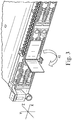
- FIG. 3 shows the rotation of the asset tag 100 upon actuation.
- the asset tag is rotated from the x plane to the z plane. Once the asset tag 100 is actuated by an indicator, the asset tag can rotate 90 degrees into the sight of a technician.
- FIGs. 4 , 5A, and 5B show the asset tag 100 once in the actuated position.
- the interface 101 becomes perpendicular to the front face of the switch device 50.
- the interface 101 and the post 102 of the asset tag 100 does not block access to the hard drives 51N(1), 51N(2), 51N(4), and 51N(5).
- the hard drives 51N(1), 51N(2), 51N(4), and 51N(5) are fully accessible by the technician.
- FIG. 5B the asset tag 100 is completely visible to a technician.
- the asset tag 100 can be oriented horizontally as well. This configuration is discussed in greater detail below with respect to FIGs. 6-10 .
- FIG. 6 shows on a larger scale, the placement of an asset tag 200 for identifying an electrical component and its physical location in a data center.
- the asset tag 200 can rotate about the x-axis in direction 240 via an actuator 203.
- the actuator 203 can include a receiver (not shown) and a power source (not shown).
- the power source can be low energy.
- the power source can be connected to the server 250, or to an independent power source.
- the power source can include electric voltage or current, pneumatic or hydraulic pressure.
- the asset tag 200 can include the interface 201 to provide information regarding the plurality of hard drives 251N.
- the interface 201 can include an indicator, to alert a technician that there is a notification regarding the plurality of hard drives 251N.
- the notification can include a failure notification.
- the interface 201 can provide an event log. Conversely, the interface 201 can simply provide an indicator, such as a QR code, for a technician to scan to receive the details of the notification.
- the interface 201 can also include specialized lighting to indicate to a technician the reason for the notification. For example, in some embodiments, a red colored lighting might be actuated to indicate an error or component malfunction. In another embodiment, a blue colored lighting might be actuated to indicate to the location of a particular component a technician needs to service or replace.
- the specialized lighting can be coded at the DCIM database 30 (shown in FIG. 1 ).
- the interface 201 can include a display that specifically details the reason for the notification. The display can be a touch screen display that receives input. In some embodiments, after servicing the component that prompted the notification, the technician can reset the flag via the touchscreen.
- the notification can also simply include an identification notification.
- the technician can interface with a DCIM (shown in FIG. 1 ) to inquire as to the status and location of a specific hard drive 251N.
- the asset tag 200 can receive instructions from the DCIM to actuate its indicator on the interface 201 to alert the technician of its location.
- the interface 201 can provide additional information for a technician regarding the status of the specific hard drive 251N.
- the interface 201 can also include an input function. For example, once the technician has serviced the corresponding server component (e.g., hard drive 251N), the technician can reset the asset tag 200 to indicate the service is complete. Furthermore, resetting the asset tag 200 via the input function can indicate to the DCIM database 30 (shown in FIG. 1 ) to perform another assessment of the server component (e.g., hard drive 251N) to ensure the task is complete.
- FIG. 7 shows a front facing view of the asset tag 200 and the server 250.
- the server 250 includes hard drives 251N(1) - 251N(6).
- the hard drives each include an access input 252N that releases the hard drives from the server 250.
- Each hard drive is disposed in a hard drive carrier (not shown) and inserted into the switch device 250.
- the hard drive carriers are separated at least near the flag by horizontal gaps 48A and 48B.
- the asset tag 200 is placed between the hard drives 251N in gap 48A.
- gap 48A represents the base of hard drive 251N(2).
- the post 202 of the asset tag 200 can be configured such that it sits just below hard drive 251N(2) in gap 48A.
- the thickness of the post 202 can be the same or less than the gap 48A.
- the thickness of the interface 201 can be the same or less than the gap 48A.
- FIG. 8 shows the rotation of the asset tag 200 upon actuation.
- the asset tag is rotated from its parallel position with the y plane to become parallel with the x plane. Once the asset tag 200 is actuated by an indicator, the asset tag can rotate 90 degrees.
- FIG. 9 and FIG. 10A-B show the asset tag 200 once in the actuated position.
- the interface 201 becomes perpendicular to the front face of the server 250.
- the interface 201 and the post 202 of the asset tag 200 do not block access to the hard drive 251N(2).
- the hard drive 251N is fully accessible by the technician.
- the asset tag 200 is completely visible to a technician.
Landscapes
- Engineering & Computer Science (AREA)
- Microelectronics & Electronic Packaging (AREA)
- Computer Hardware Design (AREA)
- General Engineering & Computer Science (AREA)
- Management, Administration, Business Operations System, And Electronic Commerce (AREA)
Abstract
Description
- The present invention relates generally to the management of data center infrastructure. More specifically, the present disclosure relates to systems, apparatuses, and methods for establishing and tracking the identity of components in the data center.
- A data center is a location used to house computer systems, where the computer systems are typically arranged in a number of racks. The management component of data centers is vital to the success of the data center. One critical task in the management of data centers is the tracking of often thousands of discrete electronic components, such as servers, switches, storage devices, and power supplies. These discrete components must all be tracked in, for example, data center infrastructure management ("DCIM") software. Such tracking is necessary for the effective operation and maintenance of a data center. For example, if a specific server starts generating errors detected over a network derived from hardware failure, then the location of the server must be quickly identified so that a technician can initiate repairs/replacement. Thus the DCIM software must know both the identity of the server, as well as its physical location.
- A rack is a frame or enclosure for mounting multiple equipment components in a data center environment. Each component has an open front panel, including edges or ears that protrude on each side. This allow the module to be fastened to the rack frame with screws. A "rack unit" or "U" (less commonly "RU") is a unit of measure used to describe the height of equipment intended for mounting in a rack, such as a standard 19-inch rack or a 23-inch rack. In such standard racks, one rack unit is 1.75 inches (44.45 mm) high. The size of a piece of rack-mounted equipment is typically described as a number in "U". For example, equipment that is one rack unit tall is often referred to as "1U"; equipment that is tworack units tall as "2U"; and so on.
- Typically, the location of a component is provided by a rack number, which identifies the rack in the DCIM database. The rack number identifies the rack location. Furthermore, a rack vertical number can be provided to determine how high up the component is placed in the rack (for example, a 7U position).
- Typically, if a specific server starts generating errors then the failed hardware may generate an indicator. This may include, for example, a blinking red light. Thus, technicians servicing a data center will often times have to canvas large areas in search of this indicator. In large data centers, it may be onerous for a technician to identify a single blinking red light in a room of thousands of discrete electronic components, such as servers, switches, storage devices, power supplies, etc. Thus, such identification is time-consuming, expensive, and prone to error. In view of the foregoing, what is needed is a means to facilitate identification of the failed component and its physical location.
- Embodiments of the invention concern a server rack. The server rack includes at least one server component and an asset tag corresponding to the at least one server component. The asset tag includes a support bar positioned such that the at least one server component is removable from the server rack, without removing the asset tag. The asset tag also includes an actuator connected to the support bar and configured to rotate the support bar between the at least two positions. Lastly, the asset tag includes an interface supported by the support bar, wherein the interface is configured to provide an indicator regarding the location and status of the corresponding server component.
- In some embodiments, the support bar is located at a horizontal gap between two subcomponents of the server component. Alternatively, in other embodiments, the support bar is located between a vertical gap that separates two subcomponents of the server component. In some embodiments, a first position of the support bar configures the interface to be flush against the server component. Alternatively, in other embodiments, a second position of the support bar configures the interface to be perpendicular to the server component. In some embodiments of the disclosure, the interface provides a notification regarding the at least one server component. In other embodiments, the notification provides information regarding the status of the at least one server component. In some embodiments, the notification provides a failure of the at least one server component.
- Embodiments of the invention concern a data center. The data center can include a server rack with multiple servers, a network, and a data center infrastructure management database. In some embodiments, the asset tag includes a support bar positioned such that the at least one server component is removable from the server rack without removing the asset tag. The asset tag also includes an interface supported by the support bar. This interface is configured to provide an indicator regarding the location and status of the corresponding server component.
-
-
FIG. 1 is schematic of a portion of a data center in accordance with embodiments of the disclosure; -
FIG. 2A shows a close up perspective view of the placement of the asset tag for identifying an associated server in a data center, in accordance with embodiments of the disclosure; -
FIG. 2B shows a close up front facing view of the asset tag and the server ofFIG. 2A ; -
FIG. 3 illustrates the rotation of the asset tag ofFIGs, 2A and 2B upon actuation, in accordance to an embodiment of the disclosure; -
FIG. 4 shows the asset tag ofFIG. 2A and 2B once in the actuated position, in accordance to an embodiment of the disclosure; -
FIG. 5A and 5B shows other views of the asset tag ofFIGs. 2A and 2B once in the actuated position, in accordance to an embodiment of the disclosure; -
FIG. 6 illustrates a perspective close-up view of the placement of a server, in accordance to an embodiment of the disclosure; -
FIG. 7 shows a close-up front facing view of the asset tag and the server ofFIG. 6 ; -
FIG. 8 illustrates the rotation of the asset tag ofFIGs. 6 and 7 upon actuation, in accordance to an embodiment of the disclosure; -
FIG. 9 shows the asset tag ofFIGs. 6 and 7 once in the actuated position, in accordance to an embodiment of the disclosure; and -
FIG. 10A and 10B show other views of the asset tag once ofFIGs. 6 and 7 in the actuated position, in accordance to an embodiment of the disclosure. - The present invention is described with reference to the attached figures, wherein like reference numerals are used throughout the figures to designate similar or equivalent elements. The figures are not drawn to scale, as they are provided merely to illustrate the instant invention. Several aspects of the invention are described below with reference to example applications for illustration. It should be understood that numerous specific details, relationships, and methods are set forth to provide a full understanding of the invention. One having ordinary skill in the relevant art, however, will readily recognize that the invention can be practiced without one or more of the specific details, or with other methods. In other instances, well-known structures or operations are not shown in detail to avoid obscuring the invention. The present invention is not limited by the illustrated ordering of acts or events, as some acts may occur in different orders and/or concurrently with other acts or events. Furthermore, not all illustrated acts or events are required to implement a methodology in accordance with the present invention.
- Embodiments of the present invention provide an asset tag to identify a failed component, such as a server, and its physical location in a data center. The asset tag is not only able to identify a failed component and its physical location, but it can also provide additional information. For example, in some embodiments, the asset tag can be an interface for a technician to discover the status and configuration Stock Keeping Unit Identifications (SKU IDs). Because the asset tag is located outside of the server components, it does not require internal space within the server component. This allows for separate installation and maintenance of the asset tag outside of the maintenance for the server component.
- An electronic interface, such as for example, a touch screen, can also be provided on the asset tag to display error and diagnostic information to the technician. In some embodiments, the asset tag may have an input function that allows a technician to reset the asset tag after service has been complete. Furthermore, the asset tag can vary in shape and design to allow for rapid, low-cost, custom fabrication of high-durability. The asset tag can also vary in shape and design to allow for accessibility of the electronic components housed on the server rack. In some embodiments, the asset tag can be affixed (or AFFIX) between electronic components to a vertical rotating member. Thus, once triggered, the asset tag can rotate into view to facilitate identification by a technician, but without obstructing access to the electronic components housed on the server rack. In alternative embodiments, the asset tag can be affixed (or AFFIX) beneath an electronic component to a horizontal rotating member. Thus, once triggered, the asset tag can rotate into view to facilitate identification by a technician, but without obstructing access to the electronic components housed on the server rack. The various configurations of the asset tag are discussed in greater detail below with respect to
FIGs. 1-10 . -
FIG. 1 shows a schematic of adata center 1. Thedata center 1 can include aserver rack 10 withmultiple switch devices 50, anetwork 20, and a data center infrastructure management ("DCIM")database 30. Eachswitch device 50 can include various components known in the art, such as central processing units, service controllers, sensors, storage devices, power supplies, fans, memory modules, etc. (not shown). Theserver rack 10 can includemultiple switch devices 50, each with acorresponding asset tag 100. In some embodiments, each component within theswitch device 50 can have acorresponding asset tag 100. In other embodiments of the disclosure, a server rack is considered an asset; thus, theserver rack 10 can have asingle asset tag 99. InFIG. 1 , eachswitch device 50 has onecorresponding asset tag 100, however, it should be noted that eachswitch device 50 can include multiple asset tags 100. Thus, different tags can be employed in different scenarios. For example, upon failure of a cooling fan within theswitch device 50, an associated asset tag can be actuated. Moreover, if a power supply within theswitch device 50 becomes compromised, an associated asset tag can be actuated. - As used herein, the terminology "tag" can be defined as hardware, information, signals and the like, that are not necessarily intrinsic to the circuitry or software associated with the assets to which the tags are associated. Thus, the tags can be externally attached to the respective assets and can be independent of the intrinsic workings of the respective assets.
- In some embodiments, the
asset tag 100 can be mounted directly on theswitch device 50; on theserver rack 10 while associated with theswitch device 50; or on theserver rack 10 and associated with theserver rack 10. In some embodiments, theasset tag 100 may be attached to the respective assets by adhesive, metal fasteners, or a combination of the two. It should be realized that many other methods of physically associating the tags with respective assets are possible, and the present disclosure is not limited to the examples set forth herein. In other words, it is not necessary to mount theasset tag 100 exactly as shown inFIG. 6 , and it is contemplated that the asset tag can be located at any other reasonably suitable location with respect to the assets. Theswitch device 50 can be mounted on theserver rack 10 and associated to anasset tag 100. While reference is made herein to a "rack system," "server," "hard drive," "service controller" and the like, it should be understood that use of the singular in the examples herein does not preclude use of the plural in various embodiments. Thus, the configuration of thedata center 1 is only for example, and not to limit this disclosure. For example, a data center can contain thousands of server racks, and multiple DCIM with corresponding networks of the data center. - The
DCIM database 30 can be located within thedata center 1, as shown inFIG. 1 . In alternative embodiments, theDCIM database 30 can be remote from thedata center 1. Each of theasset tags 100 can correspond with theDCIM database 30 overnetwork 20. Thenetwork 20 may be, for example, a local area network (LAN); a wireless local area network (WLAN); a wide area network (WAN); a metropolitan area network (MAN); a global area network; a distributed computer system, such as the Internet; and a Fibre Channel fabric. TheDCIM database 30 can send notifications to theasset tag 100 over thenetwork 20. For example, if aswitch device 50 encounters an operation error, such as a BMC error, theswitch device 50 can actuate theasset tag 100. The notification can be converted to a visual indicator at theasset tag 100 for a technician to both identity the physical location ofswitch device 50 the operation error. The content of the notification is discussed in greater detail below. -
FIG. 2A shows on a larger scale, the placement of theasset tag 100 for identifying an electrical component and its physical location in a data center. Theasset tag 100 has aninterface 101 and apost 102. Thepost 102 can be positioned at aswitch device 50. Theswitch device 50 is configured to house a plurality ofhard drives 51N. It should be noted that the configuration of theasset tag 100 at theswitch device 50 is only for example, and not to limit this disclosure. For example, theasset tag 100 can be located at a server device, a switch device, or a power supply. Theasset tag 100 can be formed from metal, plastic, composite, or a combination thereof, and configured to endure the varying heat and wear and tear of a typical data center. In certain embodiments, theasset tag 100 and its components can be made of sheet metal using conventional metal fabrication techniques such as bending, forming, and stamping. As a result, theasset tag 100 can, in some embodiments, be made inexpensively. Alternatively, theasset tag 100 and its components can be made of aluminum alloy, steel alloy, or any combination thereof. It should be realized that theasset tag 100 and its components can be made of any material with low cost of construction and durability. The materials mentioned above are only for example, and not to limit this disclosure. Thus, the present disclosure contemplates that any material or combination of materials can be used in the various embodiments without limitation. Theasset tag 100 is discussed in further detail below. - The
asset tag 100 can rotate about the y-axis indirection 40 via anactuator 103. Theactuator 103 can include a receiver (not shown) and a power source (not shown). The power source can be low energy. The power source can be connected to theswitch device 50, or to an independent power source. The power source can include electric voltage or current, pneumatic or hydraulic pressure. Theasset tag 100 can include theinterface 101 to provide information regarding the plurality ofhard drives 51N. For example, theinterface 101 can include an indicator, to alert a technician that there is a notification regarding the plurality ofhard drives 51N. In some embodiments, the indicator can include messages specifically detailing the contents of the notification. In other embodiments, the indicator can include a bar code or coded message the technician is required to scan to receive the contents of the notification. The notification can include a failure notification. For example, if theswitch device 50 encounters an operation error like a BMC error, theinterface 101 can provide an event log. Conversely, theinterface 101 can simply provide an indicator, such as a QR code, for a technician to scan to receive the details of the notification. Theinterface 101 can also include specialized lighting to indicate to a technician the reason for the notification. For example, in some embodiments, a red colored lighting might be actuated to indicate an error or component malfunction. In another embodiment, a blue colored lighting might be actuated to indicate to the location of a particular component a technician needs to service or replace. The specialized lighting can be coded at the DCIM database 30 (shown inFIG. 1 ). - The
asset tag 100 can include a component for providing local proximity sensing, such as, for example, infrared (IR) components. Theasset tag 100 can also include a component for intermediate range messaging, such as, for example, a Radio-frequency identification (RFID) component. The local proximity component of theasset tag 100 can have a range that allows the exchange of information between a technician, the corresponding asset to theasset tag 100, and neighboring assets. Because all assets in theserver rack 50 are vertically stacked, as dictated by industry standard, a neighboring asset can include the asset that is physically below or above the asset associated with theasset tag 100. In some embodiments, asingle asset flag 100 mounted to the server rack can be implemented. In such cases, the asset tag can provide notifications that specify the specific component failure. In other embodiments of the disclosure, neighboring assets can include assets located at adjacent server racks (not pictured herein). The intermediate range component can be implemented for sharing data wirelessly amongst multiple racks within thedata center 1. RF communication can provide a gross measure of location, typically to within a few meters in line of sight deployments. IR communication can be implemented as well, as it offers a more precise range of approximately between 0.2 meters and 1 meter. Both the local proximity sensing and the intermediate range sensing can be used to find the position of the asset (switch device 50) within the server rack 10 (shown inFIG. 1 ). Alternatively, theasset tag 100 can indicate its exact position to the DCIM (shown inFIG. 1 ). - The notification can also simply include an identification notification. For example, the technician can interface with a DCIM (shown in
FIG. 1 ) to inquire as to the status and location of a specifichard drive 51N. Theasset tag 100 can receive instructions from the DCIM to actuate its indicator on theinterface 101 to alert the technician of its location. Theinterface 101 can provide additional information for a technician regarding the status of the specifichard drive 51N. In some embodiments, theinterface 101 can also include an input function. For example, once the technician has serviced the corresponding server component (e.g.,hard drive 51N), the technician can reset theasset tag 100 to indicate that the service is complete. Furthermore, resetting theasset tag 100 via the input function can indicate to theDCIM database 30 to perform another assessment of the server component (e.g.,hard drive 51N) to ensure the task is complete. -
FIG. 2B shows a front facing view of theasset tag 100 and theswitch device 50. Theswitch device 50 includeshard drives 51N(1) - 51N(6). The hard drives each include anaccess input 52N that releases the hard drives from theswitch device 50. Each hard drive is disposed in a hard drive carrier (not shown) and inserted into theswitch device 50. The hard drive carriers are separated at least near the flag byvertical gaps asset tag 100 is placed between thehard drives 51N ingap 49A. In this example,gap 49A separateshard drives 51N(1) from 51N(2); and 51N(4) from 51N(5). Specifically, thepost 102 of theasset tag 100 can be configured such that it sits between thehard drives 51N(1), 51N(2), 51N(4) and 51N(5)ingap 49. Thus, the thickness of thepost 102 can be the same or less than thegap 49. Furthermore, the thickness of theinterface 101 can be the same or less than thegap 49. -
FIG. 3 shows the rotation of theasset tag 100 upon actuation. The asset tag is rotated from the x plane to the z plane. Once theasset tag 100 is actuated by an indicator, the asset tag can rotate 90 degrees into the sight of a technician. -
FIGs. 4 ,5A, and 5B show theasset tag 100 once in the actuated position. Theinterface 101 becomes perpendicular to the front face of theswitch device 50. Theinterface 101 and thepost 102 of theasset tag 100 does not block access to thehard drives 51N(1), 51N(2), 51N(4), and 51N(5). As indicated inFIG. 5A , thehard drives 51N(1), 51N(2), 51N(4), and 51N(5) are fully accessible by the technician. As shown inFIG. 5B , theasset tag 100 is completely visible to a technician. Theasset tag 100 can be oriented horizontally as well. This configuration is discussed in greater detail below with respect toFIGs. 6-10 . -
FIG. 6 shows on a larger scale, the placement of anasset tag 200 for identifying an electrical component and its physical location in a data center. Theasset tag 200 can rotate about the x-axis indirection 240 via anactuator 203. Theactuator 203 can include a receiver (not shown) and a power source (not shown). The power source can be low energy. The power source can be connected to theserver 250, or to an independent power source. The power source can include electric voltage or current, pneumatic or hydraulic pressure. Theasset tag 200 can include theinterface 201 to provide information regarding the plurality ofhard drives 251N. For example, theinterface 201 can include an indicator, to alert a technician that there is a notification regarding the plurality ofhard drives 251N. The notification can include a failure notification. For example, if theserver 250 encounters an operation error like a BMC error, theinterface 201 can provide an event log. Conversely, theinterface 201 can simply provide an indicator, such as a QR code, for a technician to scan to receive the details of the notification. Theinterface 201 can also include specialized lighting to indicate to a technician the reason for the notification. For example, in some embodiments, a red colored lighting might be actuated to indicate an error or component malfunction. In another embodiment, a blue colored lighting might be actuated to indicate to the location of a particular component a technician needs to service or replace. The specialized lighting can be coded at the DCIM database 30 (shown inFIG. 1 ). In some embodiments, theinterface 201 can include a display that specifically details the reason for the notification. The display can be a touch screen display that receives input. In some embodiments, after servicing the component that prompted the notification, the technician can reset the flag via the touchscreen. - The notification can also simply include an identification notification. For example, the technician can interface with a DCIM (shown in
FIG. 1 ) to inquire as to the status and location of a specifichard drive 251N. Theasset tag 200 can receive instructions from the DCIM to actuate its indicator on theinterface 201 to alert the technician of its location. Theinterface 201 can provide additional information for a technician regarding the status of the specifichard drive 251N. In some embodiments, theinterface 201 can also include an input function. For example, once the technician has serviced the corresponding server component (e.g.,hard drive 251N), the technician can reset theasset tag 200 to indicate the service is complete. Furthermore, resetting theasset tag 200 via the input function can indicate to the DCIM database 30 (shown inFIG. 1 ) to perform another assessment of the server component (e.g.,hard drive 251N) to ensure the task is complete. -
FIG. 7 shows a front facing view of theasset tag 200 and theserver 250. Theserver 250 includeshard drives 251N(1) - 251N(6). The hard drives each include an access input 252N that releases the hard drives from theserver 250. Each hard drive is disposed in a hard drive carrier (not shown) and inserted into theswitch device 250. The hard drive carriers are separated at least near the flag byhorizontal gaps asset tag 200 is placed between thehard drives 251N ingap 48A. In this example,gap 48A represents the base ofhard drive 251N(2). Specifically, thepost 202 of theasset tag 200 can be configured such that it sits just belowhard drive 251N(2) ingap 48A. Thus, the thickness of thepost 202 can be the same or less than thegap 48A. Furthermore, the thickness of theinterface 201 can be the same or less than thegap 48A. -
FIG. 8 shows the rotation of theasset tag 200 upon actuation. The asset tag is rotated from its parallel position with the y plane to become parallel with the x plane. Once theasset tag 200 is actuated by an indicator, the asset tag can rotate 90 degrees. -
FIG. 9 andFIG. 10A-B show theasset tag 200 once in the actuated position. Theinterface 201 becomes perpendicular to the front face of theserver 250. Theinterface 201 and thepost 202 of theasset tag 200 do not block access to thehard drive 251N(2). As indicated inFIG. 10A , thehard drive 251N is fully accessible by the technician. As shown inFIG. 10B , theasset tag 200 is completely visible to a technician. - The terminology used herein is for the purpose of describing particular embodiments only and is not intended to be limiting of the invention. As used herein, the singular forms "a", "an" and "the" are intended to include the plural forms as well, unless the context clearly indicates otherwise. Furthermore, to the extent that the terms "including", "includes", "having", "has", "with", or variants thereof are used in either the detailed description and/or the claims, such terms are intended to be inclusive in a manner similar to the term "comprising".
Claims (9)
- A server rack (10), comprising at least one server component (51N, 251N) and an asset tag (99, 100, 200) corresponding to the at least one server component (51N, 251N), wherein the asset tag (99, 100, 200) is characterized by:a support bar (102, 202) rotatable between at least two positions, wherein the support bar (102, 202) is positioned such that the server component (51N, 251N) is removable from the server rack (10) without removing the asset tag (99, 100, 200);an actuator (103, 203) connected to the support bar (102, 202) and configured to rotate the support bar (102, 202) between the at least two positions; andan interface (101, 201) supported by the support bar (102, 202), wherein the interface (101, 201) is configured to provide an indicator regarding the location and status of the corresponding server component (51N, 251N).
- The server rack (10) of claim 1, wherein the support bar (102, 202) is located at a horizontal gap between two subcomponents of the server component (51N, 251N).
- The server rack (10) of claim 1, wherein the support bar (102, 202) is located between a vertical gap between two subcomponents of the server component (51N, 251N).
- The server rack (10) of claim 1, wherein a first position of the support bar (102, 202) configures the interface (101, 201) to be flush against the server component (51N, 251N), and a second position of the support bar (102, 202) configures the interface (101, 201) to be perpendicular to the server component (51N, 251N).
- The server rack (10) of claim 1, wherein the interface (101, 201) provides a notification regarding the at least one server component (51N, 251N).
- The server rack (10) of claim 5, wherein the notification provides information regarding the status of the at least one server component (51N, 251N).
- The server rack (10) of claim 5, wherein the notification provides a failure of the at least one server component (51N, 251N).
- The server rack (10) of claim 1, wherein the interface (101, 201) comprises a display.
- The server rack (10) of claim 1, wherein the interface (101, 201) comprises a touch screen display.
Applications Claiming Priority (1)
| Application Number | Priority Date | Filing Date | Title |
|---|---|---|---|
| US15/715,986 US10595434B2 (en) | 2017-09-26 | 2017-09-26 | Asset tag holder mechanism to improve accessibility |
Publications (2)
| Publication Number | Publication Date |
|---|---|
| EP3461243A1 true EP3461243A1 (en) | 2019-03-27 |
| EP3461243B1 EP3461243B1 (en) | 2019-10-09 |
Family
ID=61131980
Family Applications (1)
| Application Number | Title | Priority Date | Filing Date |
|---|---|---|---|
| EP18153463.7A Active EP3461243B1 (en) | 2017-09-26 | 2018-01-25 | Asset tag holder mechanism to improve accessibility |
Country Status (5)
| Country | Link |
|---|---|
| US (1) | US10595434B2 (en) |
| EP (1) | EP3461243B1 (en) |
| JP (1) | JP6626921B2 (en) |
| CN (1) | CN109561621B (en) |
| TW (1) | TWI628997B (en) |
Families Citing this family (4)
| Publication number | Priority date | Publication date | Assignee | Title |
|---|---|---|---|---|
| US10839720B1 (en) * | 2019-07-08 | 2020-11-17 | T And B Innovations Inc. | IT server tag, and method of labeling server channels |
| US11395441B2 (en) * | 2020-03-23 | 2022-07-19 | Quanta Computer Inc. | Systems and methods for operating a flap |
| US12399794B2 (en) * | 2022-04-14 | 2025-08-26 | Panduit Corp. | Infrastructure management system and method |
| US20250036179A1 (en) * | 2023-07-30 | 2025-01-30 | Vertiv Corporation | Display mount |
Citations (6)
| Publication number | Priority date | Publication date | Assignee | Title |
|---|---|---|---|---|
| US20060227154A1 (en) * | 2005-04-12 | 2006-10-12 | Hewlett-Packard Development Company, Lp | Electronic device display panel |
| US20080068199A1 (en) * | 2006-09-13 | 2008-03-20 | Franz John P | Computer system indicator panel with exposed indicator edge |
| US20090189767A1 (en) * | 2008-01-29 | 2009-07-30 | Rf Code, Inc. | Asset tracking system for electronic equipment |
| US20120050974A1 (en) * | 2010-09-01 | 2012-03-01 | Wistron Corporation | Electronic device having stowable display unit |
| US20120307456A1 (en) * | 2011-06-03 | 2012-12-06 | Hon Hai Precision Industry Co., Ltd. | Network cabinet |
| US20140253289A1 (en) * | 2013-03-08 | 2014-09-11 | Noah Groth | Data center server location and monitoring system |
Family Cites Families (11)
| Publication number | Priority date | Publication date | Assignee | Title |
|---|---|---|---|---|
| JP3684810B2 (en) * | 1998-01-27 | 2005-08-17 | 松下電工株式会社 | Remote monitoring and control system |
| GB2360932B (en) | 2000-04-07 | 2002-03-06 | Sun Microsystems Inc | Rack mountable display apparatus |
| US7738242B2 (en) * | 2004-01-08 | 2010-06-15 | Hewlett-Packard Development Company, L.P. | System and method for displaying chassis component information |
| CN2718666Y (en) * | 2004-08-10 | 2005-08-17 | 广达电脑股份有限公司 | Blade servo system |
| JP4902966B2 (en) | 2005-03-31 | 2012-03-21 | 富士通コンポーネント株式会社 | Movable console device |
| US7619897B2 (en) * | 2006-10-31 | 2009-11-17 | Hewlett-Packard Development Company, L.P. | User interface module for a server chassis |
| US8161391B2 (en) * | 2007-06-12 | 2012-04-17 | Hewlett-Packard Development Company, L.P. | On-board input and management device for a computing system |
| TWI485549B (en) | 2009-12-23 | 2015-05-21 | Aten Int Co Ltd | Kvm switch and the supporting structure thereof |
| US9342103B2 (en) * | 2011-06-30 | 2016-05-17 | Hewlett Packard Enterprise Development Lp | Hinged bezel having a portable display dock |
| TW201406270A (en) | 2012-07-16 | 2014-02-01 | Delta Electronics Inc | Control device and rack using same |
| JP6191376B2 (en) | 2013-10-11 | 2017-09-06 | 日本電気株式会社 | Server installation position management system, server installation position management method, and program |
-
2017
- 2017-09-26 US US15/715,986 patent/US10595434B2/en active Active
- 2017-12-08 TW TW106143250A patent/TWI628997B/en active
- 2017-12-26 CN CN201711429778.4A patent/CN109561621B/en active Active
-
2018
- 2018-01-25 EP EP18153463.7A patent/EP3461243B1/en active Active
- 2018-04-09 JP JP2018075036A patent/JP6626921B2/en active Active
Patent Citations (6)
| Publication number | Priority date | Publication date | Assignee | Title |
|---|---|---|---|---|
| US20060227154A1 (en) * | 2005-04-12 | 2006-10-12 | Hewlett-Packard Development Company, Lp | Electronic device display panel |
| US20080068199A1 (en) * | 2006-09-13 | 2008-03-20 | Franz John P | Computer system indicator panel with exposed indicator edge |
| US20090189767A1 (en) * | 2008-01-29 | 2009-07-30 | Rf Code, Inc. | Asset tracking system for electronic equipment |
| US20120050974A1 (en) * | 2010-09-01 | 2012-03-01 | Wistron Corporation | Electronic device having stowable display unit |
| US20120307456A1 (en) * | 2011-06-03 | 2012-12-06 | Hon Hai Precision Industry Co., Ltd. | Network cabinet |
| US20140253289A1 (en) * | 2013-03-08 | 2014-09-11 | Noah Groth | Data center server location and monitoring system |
Also Published As
| Publication number | Publication date |
|---|---|
| JP2019061649A (en) | 2019-04-18 |
| EP3461243B1 (en) | 2019-10-09 |
| US10595434B2 (en) | 2020-03-17 |
| JP6626921B2 (en) | 2019-12-25 |
| CN109561621B (en) | 2020-11-27 |
| CN109561621A (en) | 2019-04-02 |
| TWI628997B (en) | 2018-07-01 |
| TW201916781A (en) | 2019-04-16 |
| US20190098794A1 (en) | 2019-03-28 |
Similar Documents
| Publication | Publication Date | Title |
|---|---|---|
| EP3461243B1 (en) | Asset tag holder mechanism to improve accessibility | |
| JP5911885B2 (en) | Safety contact configuration & cabinet | |
| US20130031202A1 (en) | Using Augmented Reality To Create An Interface For Datacenter And Systems Management | |
| US10198709B2 (en) | Managing assets using at least one policy and asset locations | |
| US20140253289A1 (en) | Data center server location and monitoring system | |
| US8779922B2 (en) | Data center equipment location and monitoring system | |
| EP2556733A1 (en) | Asset identification and tracking system and method | |
| CN104619021B (en) | Personnel positioning method and positioning system in computer room based on RFID | |
| US20080265722A1 (en) | Intelligent track system for mounting electronic equipment | |
| KR100872398B1 (en) | Electric power facility management system using electronic tag | |
| US9049802B2 (en) | Apparatus for receiving servers | |
| CN104166900A (en) | IDC machine room device management system and method | |
| US20190086877A1 (en) | Method and Apparatus for Cloud Based Predictive Service Scheduling and Evaluation | |
| US20070107211A1 (en) | A system for monitoring and controlling operation of a machine having a detachable tool | |
| US20150334355A1 (en) | System for asset management | |
| US10477721B2 (en) | Mechanism to provide physical location information to any network device | |
| CN103246251A (en) | Tool and apparatus management and monitoring system of hot-line work tool and apparatus storehouse | |
| US20150170499A1 (en) | Dynamic activation of service indicators based upon service personnel proximity | |
| CN118378983A (en) | Machine room management system and method based on RFID technology | |
| US20070106574A1 (en) | Inventory management system and method for a cellular communications system | |
| CN112825163A (en) | Property operation and maintenance management system and use method thereof | |
| US20210012296A1 (en) | Network Extended Support System | |
| US20140297180A1 (en) | Mobilized Sensor System | |
| CN204496266U (en) | A kind of computer room management system | |
| CN217157313U (en) | Workstation and factory production management system |
Legal Events
| Date | Code | Title | Description |
|---|---|---|---|
| PUAI | Public reference made under article 153(3) epc to a published international application that has entered the european phase |
Free format text: ORIGINAL CODE: 0009012 |
|
| STAA | Information on the status of an ep patent application or granted ep patent |
Free format text: STATUS: THE APPLICATION HAS BEEN PUBLISHED |
|
| AK | Designated contracting states |
Kind code of ref document: A1 Designated state(s): AL AT BE BG CH CY CZ DE DK EE ES FI FR GB GR HR HU IE IS IT LI LT LU LV MC MK MT NL NO PL PT RO RS SE SI SK SM TR |
|
| AX | Request for extension of the european patent |
Extension state: BA ME |
|
| STAA | Information on the status of an ep patent application or granted ep patent |
Free format text: STATUS: REQUEST FOR EXAMINATION WAS MADE |
|
| GRAP | Despatch of communication of intention to grant a patent |
Free format text: ORIGINAL CODE: EPIDOSNIGR1 |
|
| STAA | Information on the status of an ep patent application or granted ep patent |
Free format text: STATUS: GRANT OF PATENT IS INTENDED |
|
| 17P | Request for examination filed |
Effective date: 20190430 |
|
| RBV | Designated contracting states (corrected) |
Designated state(s): AL AT BE BG CH CY CZ DE DK EE ES FI FR GB GR HR HU IE IS IT LI LT LU LV MC MK MT NL NO PL PT RO RS SE SI SK SM TR |
|
| RIC1 | Information provided on ipc code assigned before grant |
Ipc: H05K 7/18 20060101ALI20190516BHEP Ipc: H05K 7/14 20060101AFI20190516BHEP Ipc: H05K 7/16 20060101ALI20190516BHEP |
|
| INTG | Intention to grant announced |
Effective date: 20190604 |
|
| GRAS | Grant fee paid |
Free format text: ORIGINAL CODE: EPIDOSNIGR3 |
|
| GRAA | (expected) grant |
Free format text: ORIGINAL CODE: 0009210 |
|
| STAA | Information on the status of an ep patent application or granted ep patent |
Free format text: STATUS: THE PATENT HAS BEEN GRANTED |
|
| RIN1 | Information on inventor provided before grant (corrected) |
Inventor name: CHEN, CHAO-JUNG Inventor name: LIU, KUN-PEI |
|
| AK | Designated contracting states |
Kind code of ref document: B1 Designated state(s): AL AT BE BG CH CY CZ DE DK EE ES FI FR GB GR HR HU IE IS IT LI LT LU LV MC MK MT NL NO PL PT RO RS SE SI SK SM TR |
|
| REG | Reference to a national code |
Ref country code: GB Ref legal event code: FG4D |
|
| REG | Reference to a national code |
Ref country code: CH Ref legal event code: EP |
|
| REG | Reference to a national code |
Ref country code: IE Ref legal event code: FG4D |
|
| REG | Reference to a national code |
Ref country code: DE Ref legal event code: R096 Ref document number: 602018000796 Country of ref document: DE |
|
| REG | Reference to a national code |
Ref country code: AT Ref legal event code: REF Ref document number: 1190370 Country of ref document: AT Kind code of ref document: T Effective date: 20191115 |
|
| REG | Reference to a national code |
Ref country code: NL Ref legal event code: MP Effective date: 20191009 |
|
| REG | Reference to a national code |
Ref country code: LT Ref legal event code: MG4D |
|
| REG | Reference to a national code |
Ref country code: AT Ref legal event code: MK05 Ref document number: 1190370 Country of ref document: AT Kind code of ref document: T Effective date: 20191009 |
|
| PG25 | Lapsed in a contracting state [announced via postgrant information from national office to epo] |
Ref country code: GR Free format text: LAPSE BECAUSE OF FAILURE TO SUBMIT A TRANSLATION OF THE DESCRIPTION OR TO PAY THE FEE WITHIN THE PRESCRIBED TIME-LIMIT Effective date: 20200110 Ref country code: PT Free format text: LAPSE BECAUSE OF FAILURE TO SUBMIT A TRANSLATION OF THE DESCRIPTION OR TO PAY THE FEE WITHIN THE PRESCRIBED TIME-LIMIT Effective date: 20200210 Ref country code: ES Free format text: LAPSE BECAUSE OF FAILURE TO SUBMIT A TRANSLATION OF THE DESCRIPTION OR TO PAY THE FEE WITHIN THE PRESCRIBED TIME-LIMIT Effective date: 20191009 Ref country code: LV Free format text: LAPSE BECAUSE OF FAILURE TO SUBMIT A TRANSLATION OF THE DESCRIPTION OR TO PAY THE FEE WITHIN THE PRESCRIBED TIME-LIMIT Effective date: 20191009 Ref country code: SE Free format text: LAPSE BECAUSE OF FAILURE TO SUBMIT A TRANSLATION OF THE DESCRIPTION OR TO PAY THE FEE WITHIN THE PRESCRIBED TIME-LIMIT Effective date: 20191009 Ref country code: NO Free format text: LAPSE BECAUSE OF FAILURE TO SUBMIT A TRANSLATION OF THE DESCRIPTION OR TO PAY THE FEE WITHIN THE PRESCRIBED TIME-LIMIT Effective date: 20200109 Ref country code: PL Free format text: LAPSE BECAUSE OF FAILURE TO SUBMIT A TRANSLATION OF THE DESCRIPTION OR TO PAY THE FEE WITHIN THE PRESCRIBED TIME-LIMIT Effective date: 20191009 Ref country code: BG Free format text: LAPSE BECAUSE OF FAILURE TO SUBMIT A TRANSLATION OF THE DESCRIPTION OR TO PAY THE FEE WITHIN THE PRESCRIBED TIME-LIMIT Effective date: 20200109 Ref country code: FI Free format text: LAPSE BECAUSE OF FAILURE TO SUBMIT A TRANSLATION OF THE DESCRIPTION OR TO PAY THE FEE WITHIN THE PRESCRIBED TIME-LIMIT Effective date: 20191009 Ref country code: LT Free format text: LAPSE BECAUSE OF FAILURE TO SUBMIT A TRANSLATION OF THE DESCRIPTION OR TO PAY THE FEE WITHIN THE PRESCRIBED TIME-LIMIT Effective date: 20191009 Ref country code: NL Free format text: LAPSE BECAUSE OF FAILURE TO SUBMIT A TRANSLATION OF THE DESCRIPTION OR TO PAY THE FEE WITHIN THE PRESCRIBED TIME-LIMIT Effective date: 20191009 Ref country code: AT Free format text: LAPSE BECAUSE OF FAILURE TO SUBMIT A TRANSLATION OF THE DESCRIPTION OR TO PAY THE FEE WITHIN THE PRESCRIBED TIME-LIMIT Effective date: 20191009 |
|
| PG25 | Lapsed in a contracting state [announced via postgrant information from national office to epo] |
Ref country code: IS Free format text: LAPSE BECAUSE OF FAILURE TO SUBMIT A TRANSLATION OF THE DESCRIPTION OR TO PAY THE FEE WITHIN THE PRESCRIBED TIME-LIMIT Effective date: 20200224 Ref country code: RS Free format text: LAPSE BECAUSE OF FAILURE TO SUBMIT A TRANSLATION OF THE DESCRIPTION OR TO PAY THE FEE WITHIN THE PRESCRIBED TIME-LIMIT Effective date: 20191009 Ref country code: HR Free format text: LAPSE BECAUSE OF FAILURE TO SUBMIT A TRANSLATION OF THE DESCRIPTION OR TO PAY THE FEE WITHIN THE PRESCRIBED TIME-LIMIT Effective date: 20191009 |
|
| PG25 | Lapsed in a contracting state [announced via postgrant information from national office to epo] |
Ref country code: AL Free format text: LAPSE BECAUSE OF FAILURE TO SUBMIT A TRANSLATION OF THE DESCRIPTION OR TO PAY THE FEE WITHIN THE PRESCRIBED TIME-LIMIT Effective date: 20191009 |
|
| REG | Reference to a national code |
Ref country code: DE Ref legal event code: R097 Ref document number: 602018000796 Country of ref document: DE |
|
| PG2D | Information on lapse in contracting state deleted |
Ref country code: IS |
|
| PG25 | Lapsed in a contracting state [announced via postgrant information from national office to epo] |
Ref country code: RO Free format text: LAPSE BECAUSE OF FAILURE TO SUBMIT A TRANSLATION OF THE DESCRIPTION OR TO PAY THE FEE WITHIN THE PRESCRIBED TIME-LIMIT Effective date: 20191009 Ref country code: DK Free format text: LAPSE BECAUSE OF FAILURE TO SUBMIT A TRANSLATION OF THE DESCRIPTION OR TO PAY THE FEE WITHIN THE PRESCRIBED TIME-LIMIT Effective date: 20191009 Ref country code: EE Free format text: LAPSE BECAUSE OF FAILURE TO SUBMIT A TRANSLATION OF THE DESCRIPTION OR TO PAY THE FEE WITHIN THE PRESCRIBED TIME-LIMIT Effective date: 20191009 Ref country code: CZ Free format text: LAPSE BECAUSE OF FAILURE TO SUBMIT A TRANSLATION OF THE DESCRIPTION OR TO PAY THE FEE WITHIN THE PRESCRIBED TIME-LIMIT Effective date: 20191009 Ref country code: IS Free format text: LAPSE BECAUSE OF FAILURE TO SUBMIT A TRANSLATION OF THE DESCRIPTION OR TO PAY THE FEE WITHIN THE PRESCRIBED TIME-LIMIT Effective date: 20200209 |
|
| PLBE | No opposition filed within time limit |
Free format text: ORIGINAL CODE: 0009261 |
|
| STAA | Information on the status of an ep patent application or granted ep patent |
Free format text: STATUS: NO OPPOSITION FILED WITHIN TIME LIMIT |
|
| PG25 | Lapsed in a contracting state [announced via postgrant information from national office to epo] |
Ref country code: IT Free format text: LAPSE BECAUSE OF FAILURE TO SUBMIT A TRANSLATION OF THE DESCRIPTION OR TO PAY THE FEE WITHIN THE PRESCRIBED TIME-LIMIT Effective date: 20191009 Ref country code: SM Free format text: LAPSE BECAUSE OF FAILURE TO SUBMIT A TRANSLATION OF THE DESCRIPTION OR TO PAY THE FEE WITHIN THE PRESCRIBED TIME-LIMIT Effective date: 20191009 Ref country code: SK Free format text: LAPSE BECAUSE OF FAILURE TO SUBMIT A TRANSLATION OF THE DESCRIPTION OR TO PAY THE FEE WITHIN THE PRESCRIBED TIME-LIMIT Effective date: 20191009 Ref country code: MC Free format text: LAPSE BECAUSE OF FAILURE TO SUBMIT A TRANSLATION OF THE DESCRIPTION OR TO PAY THE FEE WITHIN THE PRESCRIBED TIME-LIMIT Effective date: 20191009 |
|
| 26N | No opposition filed |
Effective date: 20200710 |
|
| REG | Reference to a national code |
Ref country code: BE Ref legal event code: MM Effective date: 20200131 |
|
| PG25 | Lapsed in a contracting state [announced via postgrant information from national office to epo] |
Ref country code: LU Free format text: LAPSE BECAUSE OF NON-PAYMENT OF DUE FEES Effective date: 20200125 |
|
| PG25 | Lapsed in a contracting state [announced via postgrant information from national office to epo] |
Ref country code: BE Free format text: LAPSE BECAUSE OF NON-PAYMENT OF DUE FEES Effective date: 20200131 Ref country code: SI Free format text: LAPSE BECAUSE OF FAILURE TO SUBMIT A TRANSLATION OF THE DESCRIPTION OR TO PAY THE FEE WITHIN THE PRESCRIBED TIME-LIMIT Effective date: 20191009 |
|
| PG25 | Lapsed in a contracting state [announced via postgrant information from national office to epo] |
Ref country code: IE Free format text: LAPSE BECAUSE OF NON-PAYMENT OF DUE FEES Effective date: 20200125 |
|
| REG | Reference to a national code |
Ref country code: CH Ref legal event code: PL |
|
| PG25 | Lapsed in a contracting state [announced via postgrant information from national office to epo] |
Ref country code: LI Free format text: LAPSE BECAUSE OF NON-PAYMENT OF DUE FEES Effective date: 20210131 Ref country code: CH Free format text: LAPSE BECAUSE OF NON-PAYMENT OF DUE FEES Effective date: 20210131 |
|
| PG25 | Lapsed in a contracting state [announced via postgrant information from national office to epo] |
Ref country code: TR Free format text: LAPSE BECAUSE OF FAILURE TO SUBMIT A TRANSLATION OF THE DESCRIPTION OR TO PAY THE FEE WITHIN THE PRESCRIBED TIME-LIMIT Effective date: 20191009 Ref country code: MT Free format text: LAPSE BECAUSE OF FAILURE TO SUBMIT A TRANSLATION OF THE DESCRIPTION OR TO PAY THE FEE WITHIN THE PRESCRIBED TIME-LIMIT Effective date: 20191009 Ref country code: CY Free format text: LAPSE BECAUSE OF FAILURE TO SUBMIT A TRANSLATION OF THE DESCRIPTION OR TO PAY THE FEE WITHIN THE PRESCRIBED TIME-LIMIT Effective date: 20191009 |
|
| PG25 | Lapsed in a contracting state [announced via postgrant information from national office to epo] |
Ref country code: MK Free format text: LAPSE BECAUSE OF FAILURE TO SUBMIT A TRANSLATION OF THE DESCRIPTION OR TO PAY THE FEE WITHIN THE PRESCRIBED TIME-LIMIT Effective date: 20191009 |
|
| PGFP | Annual fee paid to national office [announced via postgrant information from national office to epo] |
Ref country code: GB Payment date: 20251204 Year of fee payment: 9 |
|
| PGFP | Annual fee paid to national office [announced via postgrant information from national office to epo] |
Ref country code: FR Payment date: 20251128 Year of fee payment: 9 |
|
| PGFP | Annual fee paid to national office [announced via postgrant information from national office to epo] |
Ref country code: DE Payment date: 20251203 Year of fee payment: 9 |