EP3461230A1 - Chokes for microwave dryers that block microwave energy and facilitate drying - Google Patents
Chokes for microwave dryers that block microwave energy and facilitate drying Download PDFInfo
- Publication number
- EP3461230A1 EP3461230A1 EP18195178.1A EP18195178A EP3461230A1 EP 3461230 A1 EP3461230 A1 EP 3461230A1 EP 18195178 A EP18195178 A EP 18195178A EP 3461230 A1 EP3461230 A1 EP 3461230A1
- Authority
- EP
- European Patent Office
- Prior art keywords
- layer
- choke
- microwave
- microwave radiation
- choke plate
- Prior art date
- Legal status (The legal status is an assumption and is not a legal conclusion. Google has not performed a legal analysis and makes no representation as to the accuracy of the status listed.)
- Granted
Links
Images




Classifications
-
- B—PERFORMING OPERATIONS; TRANSPORTING
- B41—PRINTING; LINING MACHINES; TYPEWRITERS; STAMPS
- B41J—TYPEWRITERS; SELECTIVE PRINTING MECHANISMS, i.e. MECHANISMS PRINTING OTHERWISE THAN FROM A FORME; CORRECTION OF TYPOGRAPHICAL ERRORS
- B41J11/00—Devices or arrangements of selective printing mechanisms, e.g. ink-jet printers or thermal printers, for supporting or handling copy material in sheet or web form
- B41J11/0015—Devices or arrangements of selective printing mechanisms, e.g. ink-jet printers or thermal printers, for supporting or handling copy material in sheet or web form for treating before, during or after printing or for uniform coating or laminating the copy material before or after printing
- B41J11/002—Curing or drying the ink on the copy materials, e.g. by heating or irradiating
- B41J11/0021—Curing or drying the ink on the copy materials, e.g. by heating or irradiating using irradiation
- B41J11/00216—Curing or drying the ink on the copy materials, e.g. by heating or irradiating using irradiation using infrared [IR] radiation or microwaves
-
- F—MECHANICAL ENGINEERING; LIGHTING; HEATING; WEAPONS; BLASTING
- F26—DRYING
- F26B—DRYING SOLID MATERIALS OR OBJECTS BY REMOVING LIQUID THEREFROM
- F26B13/00—Machines and apparatus for drying fabrics, fibres, yarns, or other materials in long lengths, with progressive movement
-
- F—MECHANICAL ENGINEERING; LIGHTING; HEATING; WEAPONS; BLASTING
- F26—DRYING
- F26B—DRYING SOLID MATERIALS OR OBJECTS BY REMOVING LIQUID THEREFROM
- F26B15/00—Machines or apparatus for drying objects with progressive movement; Machines or apparatus with progressive movement for drying batches of material in compact form
- F26B15/10—Machines or apparatus for drying objects with progressive movement; Machines or apparatus with progressive movement for drying batches of material in compact form with movement in a path composed of one or more straight lines, e.g. compound, the movement being in alternate horizontal and vertical directions
- F26B15/12—Machines or apparatus for drying objects with progressive movement; Machines or apparatus with progressive movement for drying batches of material in compact form with movement in a path composed of one or more straight lines, e.g. compound, the movement being in alternate horizontal and vertical directions the lines being all horizontal or slightly inclined
- F26B15/14—Machines or apparatus for drying objects with progressive movement; Machines or apparatus with progressive movement for drying batches of material in compact form with movement in a path composed of one or more straight lines, e.g. compound, the movement being in alternate horizontal and vertical directions the lines being all horizontal or slightly inclined the objects or batches of materials being carried by trays or racks or receptacles, which may be connected to endless chains or belts
-
- F—MECHANICAL ENGINEERING; LIGHTING; HEATING; WEAPONS; BLASTING
- F26—DRYING
- F26B—DRYING SOLID MATERIALS OR OBJECTS BY REMOVING LIQUID THEREFROM
- F26B3/00—Drying solid materials or objects by processes involving the application of heat
- F26B3/28—Drying solid materials or objects by processes involving the application of heat by radiation, e.g. from the sun
- F26B3/30—Drying solid materials or objects by processes involving the application of heat by radiation, e.g. from the sun from infrared-emitting elements
-
- F—MECHANICAL ENGINEERING; LIGHTING; HEATING; WEAPONS; BLASTING
- F26—DRYING
- F26B—DRYING SOLID MATERIALS OR OBJECTS BY REMOVING LIQUID THEREFROM
- F26B3/00—Drying solid materials or objects by processes involving the application of heat
- F26B3/32—Drying solid materials or objects by processes involving the application of heat by development of heat within the materials or objects to be dried, e.g. by fermentation or other microbiological action
- F26B3/34—Drying solid materials or objects by processes involving the application of heat by development of heat within the materials or objects to be dried, e.g. by fermentation or other microbiological action by using electrical effects
- F26B3/343—Drying solid materials or objects by processes involving the application of heat by development of heat within the materials or objects to be dried, e.g. by fermentation or other microbiological action by using electrical effects in combination with convection
-
- F—MECHANICAL ENGINEERING; LIGHTING; HEATING; WEAPONS; BLASTING
- F26—DRYING
- F26B—DRYING SOLID MATERIALS OR OBJECTS BY REMOVING LIQUID THEREFROM
- F26B3/00—Drying solid materials or objects by processes involving the application of heat
- F26B3/32—Drying solid materials or objects by processes involving the application of heat by development of heat within the materials or objects to be dried, e.g. by fermentation or other microbiological action
- F26B3/34—Drying solid materials or objects by processes involving the application of heat by development of heat within the materials or objects to be dried, e.g. by fermentation or other microbiological action by using electrical effects
- F26B3/347—Electromagnetic heating, e.g. induction heating or heating using microwave energy
-
- H—ELECTRICITY
- H05—ELECTRIC TECHNIQUES NOT OTHERWISE PROVIDED FOR
- H05B—ELECTRIC HEATING; ELECTRIC LIGHT SOURCES NOT OTHERWISE PROVIDED FOR; CIRCUIT ARRANGEMENTS FOR ELECTRIC LIGHT SOURCES, IN GENERAL
- H05B6/00—Heating by electric, magnetic or electromagnetic fields
- H05B6/64—Heating using microwaves
- H05B6/647—Aspects related to microwave heating combined with other heating techniques
- H05B6/6491—Aspects related to microwave heating combined with other heating techniques combined with the use of susceptors
-
- H—ELECTRICITY
- H05—ELECTRIC TECHNIQUES NOT OTHERWISE PROVIDED FOR
- H05B—ELECTRIC HEATING; ELECTRIC LIGHT SOURCES NOT OTHERWISE PROVIDED FOR; CIRCUIT ARRANGEMENTS FOR ELECTRIC LIGHT SOURCES, IN GENERAL
- H05B6/00—Heating by electric, magnetic or electromagnetic fields
- H05B6/64—Heating using microwaves
- H05B6/76—Prevention of microwave leakage, e.g. door sealings
-
- H—ELECTRICITY
- H05—ELECTRIC TECHNIQUES NOT OTHERWISE PROVIDED FOR
- H05B—ELECTRIC HEATING; ELECTRIC LIGHT SOURCES NOT OTHERWISE PROVIDED FOR; CIRCUIT ARRANGEMENTS FOR ELECTRIC LIGHT SOURCES, IN GENERAL
- H05B6/00—Heating by electric, magnetic or electromagnetic fields
- H05B6/64—Heating using microwaves
- H05B6/78—Arrangements for continuous movement of material
-
- H—ELECTRICITY
- H05—ELECTRIC TECHNIQUES NOT OTHERWISE PROVIDED FOR
- H05B—ELECTRIC HEATING; ELECTRIC LIGHT SOURCES NOT OTHERWISE PROVIDED FOR; CIRCUIT ARRANGEMENTS FOR ELECTRIC LIGHT SOURCES, IN GENERAL
- H05B6/00—Heating by electric, magnetic or electromagnetic fields
- H05B6/64—Heating using microwaves
- H05B6/78—Arrangements for continuous movement of material
- H05B6/788—Arrangements for continuous movement of material wherein an elongated material is moved by applying a mechanical tension to it
-
- B—PERFORMING OPERATIONS; TRANSPORTING
- B41—PRINTING; LINING MACHINES; TYPEWRITERS; STAMPS
- B41M—PRINTING, DUPLICATING, MARKING, OR COPYING PROCESSES; COLOUR PRINTING
- B41M7/00—After-treatment of prints, e.g. heating, irradiating, setting of the ink, protection of the printed stock
- B41M7/009—After-treatment of prints, e.g. heating, irradiating, setting of the ink, protection of the printed stock using thermal means, e.g. infrared radiation, heat
-
- H—ELECTRICITY
- H05—ELECTRIC TECHNIQUES NOT OTHERWISE PROVIDED FOR
- H05B—ELECTRIC HEATING; ELECTRIC LIGHT SOURCES NOT OTHERWISE PROVIDED FOR; CIRCUIT ARRANGEMENTS FOR ELECTRIC LIGHT SOURCES, IN GENERAL
- H05B2206/00—Aspects relating to heating by electric, magnetic, or electromagnetic fields covered by group H05B6/00
- H05B2206/04—Heating using microwaves
- H05B2206/046—Microwave drying of wood, ink, food, ceramic, sintering of ceramic, clothes, hair
Definitions
- the invention relates to the field of dryers, and in particular, to continuous-process microwave dryers.
- a concentration of material 230 within lower layer 212 may decrease.
- material 230 may ramp down in concentration linearly within lower layer 212 as D2 increases, from a first concentration (e.g., fifty percent) to a second concentration (e.g., ten percent).
- Choke plate 600 may be utilized as an upper choke plate at its current orientation, or may be flipped vertically to operate as a lower choke plate. While only one row of chambers 632 is illustrated in this embodiment, in further embodiments multiple rows of chambers 632 may be disposed within layer 610.
Landscapes
- Engineering & Computer Science (AREA)
- Physics & Mathematics (AREA)
- Electromagnetism (AREA)
- Life Sciences & Earth Sciences (AREA)
- Microbiology (AREA)
- General Engineering & Computer Science (AREA)
- Mechanical Engineering (AREA)
- Health & Medical Sciences (AREA)
- Molecular Biology (AREA)
- Biotechnology (AREA)
- Biomedical Technology (AREA)
- General Health & Medical Sciences (AREA)
- Toxicology (AREA)
- Textile Engineering (AREA)
- Chemical & Material Sciences (AREA)
- Combustion & Propulsion (AREA)
- Drying Of Solid Materials (AREA)
- Constitution Of High-Frequency Heating (AREA)
Abstract
Description
- The invention relates to the field of dryers, and in particular, to continuous-process microwave dryers.
- Production printing systems for high-volume printing typically utilize a production printer that marks a continuous-forms print medium (e.g., paper) with a wet colorant (e.g., an aqueous ink). After marking the continuous-forms print medium, a dryer downstream from the production printer is used to dry the colorant applied to the continuous-forms print medium. Microwave dryers may be employed as a dryer for a production printing system in some applications.
- A microwave dryer utilizes microwave energy to heat the colorant to cause a liquid portion of the colorant to evaporate, thereby fixing the colorant to the continuous-forms print medium. A microwave source directs the microwave energy down a long axis of a waveguide, and a passageway through the waveguide is sized to enable the continuous-forms print medium to pass through the waveguide. As the continuous-forms print medium traverses the passageway, wet colorant applied to the continuous-forms print medium is exposed to the microwave energy and is heated.
- To achieve a sufficient level of drying, microwave dryers generate a substantial amount of microwave radiation. This microwave radiation must be blocked before it exits the microwave dryer in order to ensure that the microwave radiation is contained within the desired dryer operating areas and that components external to the dryer are not heated by microwaves. At the same time, it remains important to reduce the path length occupied by drying systems in order to save space within a print shop.
- Embodiments described herein provide for chokes that attenuate microwave radiation emitted from microwave dryers that dry continuous-forms print media and/or other planar substrates. The chokes have been enhanced to convert microwave radiation into heat, thereby ensuring that drying continues as the continuous-forms media proceeds through the chokes. Furthermore, the chokes may utilize a substance that is transparent to microwave radiation in order to structurally support (e.g., encase) a material that performs the conversion of microwave radiation into heat.
- One embodiment is an apparatus that includes a choke assembly. The assembly includes a first choke plate, and a second choke plate that is positioned a distance away from the first choke plate, resulting in a gap between the first choke plate and the second choke plate. The assembly also includes a first layer disposed at a surface of the first choke plate. The first layer includes a material that attenuates microwave radiation via dielectric heating by converting the microwave radiation into heat, and a substance, disposed between the material of the first layer and the gap, that is transparent to the microwave radiation. The assembly further includes a second layer disposed at a surface of the second choke plate that faces the first layer. The second layer comprises the material that attenuates the microwave radiation via dielectric heating by converting the microwave radiation into heat, and the substance, disposed between the material of the second layer and the gap, that is transparent to the microwave radiation.
- A further embodiment is a system that includes a microwave dryer that applies microwave radiation to a planar substrate traveling through a waveguide of the microwave dryer in a process direction, and a choke assembly downstream of the microwave dryer. The choke assembly includes a first choke plate, and a second choke plate that is positioned a distance away from the first choke plate, resulting in a gap between the first choke plate and the second choke plate for receiving a planar substrate. The assembly also includes a first layer disposed at a surface of the upper choke plate. The first layer includes a material that attenuates microwave radiation via dielectric heating by converting the microwave radiation into heat; and a substance, disposed between the material of the first layer and the gap, that is transparent to the microwave radiation. The first layer also includes a second layer disposed at a surface of the second choke plate that faces the first layer. The second layer includes the material that attenuates the microwave radiation via dielectric heating by converting the microwave radiation into heat; and the substance, disposed between the material of the second layer and the gap, that is transparent to the microwave radiation.
- A further embodiment is a method. The method includes drying a planar substrate via microwave radiation while a planar substrate travels in a process direction through a waveguide of a microwave dryer, transporting the planar substrate through a choke assembly disposed downstream of the microwave dryer, and receiving microwave radiation at the choke assembly from an opening of the microwave dryer via which the planar substrate exits the microwave dryer. The method also includes permitting the microwave radiation to transparently pass through a solid component of the choke assembly, and performing dielectric heating by converting received microwave radiation into heat, wherein the dielectric heating is performed by a material disposed along an interior of the choke assembly.
- Other illustrative embodiments (e.g., methods and computer-readable media relating to the foregoing embodiments) may be described below.
- Some embodiments of the present invention are now described, by way of example only, and with reference to the accompanying drawings. The same reference number represents the same element or the same type of element on all drawings.
-
FIG. 1 is a block diagram of a printing system in an illustrative embodiment. -
FIG. 2 is a side view of a choke assembly for a microwave dryer in an illustrative embodiment. -
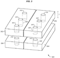
FIG. 3 is a perspective view of vent holes at a choke assembly for a microwave dryer in an illustrative embodiment. -
FIG. 4 is a flowchart illustrating a method for utilizing a choke assembly for a microwave dryer in an illustrative embodiment. -
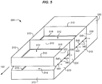
FIG. 5 is a perspective view of a frame for a choke assembly in an illustrative embodiment. -
FIG. 6 illustrates a choke plate having bore holes for receiving cylinders of material, and vent holes for providing heated air, in an illustrative embodiment. -
FIG. 7 illustrates cylinders for insertion into the bore holes ofFIG. 6 in an illustrative embodiment. -
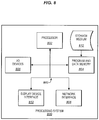
FIG. 8 illustrates a processing system operable to execute a computer readable medium embodying programmed instructions to perform desired functions in an illustrative embodiment. - The figures and the following description illustrate specific illustrative embodiments of the invention. It will thus be appreciated that those skilled in the art will be able to devise various arrangements that, although not explicitly described or shown herein, embody the principles of the invention and are included within the scope of the invention. Furthermore, any examples described herein are intended to aid in understanding the principles of the invention, and are to be construed as being without limitation to such specifically recited examples and conditions. As a result, the invention is not limited to the specific embodiments or examples described below, but by the claims and their equivalents.
-
FIG. 1 is a block diagram of aprinting system 100 in an exemplary embodiment.Printing system 100 comprises any system capable of marking print media (or other objects) and performing microwave drying as part of a continuous process. In this embodiment,printing system 100 includesprinter 110,microwave dryer 120, and planar substrate 130 (e.g., a continuous-forms print medium, a continuous transport belt bearing cut-sheet print media, etc.).Planar substrate 130 travels alongprocess direction 150 inFIG. 1 to receive marking atprinter 110 and drying atmicrowave dryer 120. -
Print controller 112 ofprinter 110 receivesprint data 116 which defines locations at which to mark underlying print media.Print data 116 may be defined according to a Page Description Language (PDL), such as Portable Document Format (PDF).Print data 116 is rasterized byprint controller 112 into bitmap data. The bitmap data is used by marking engine 114 (e.g., a drop-on-demand print engine) ofprinter 110 to apply wet colorant asplanar substrate 130 travels downstream towardsmicrowave dryer 120. In embodiments whereplanar substrate 130 is a continuous-forms print medium,planar substrate 130 is marked by markingengine 114 ofprinter 110. In embodiments whereplanar substrate 130 comprises a continuous transport belt, items being carried by planar substrate 130 (e.g., cut-sheet print media) are marked by markingengine 114 ofprinter 110. Some examples of print media include paper and textiles. Markingengine 114 may apply a wet or liquid colorant, such as one or more aqueous inks. Thus,printer 110 may comprise a continuous-forms inkjet printer, a cut-sheet inkjet printer, etc.Print controller 112 may be implemented as custom circuitry, as a hardware processor executing programmed instructions, etc. - Wet colorant applied by marking
engine 114 is dried bymicrowave dryer 120. Specifically,microwave dryer 120 applies microwave radiation 126 (e.g., microwave energy) fromsource 124 alongwaveguide 122, which is disposed within housing 125 (e.g., a steel housing).Microwave radiation 126 heats wet colorant by electromagnetic heating (i.e., dielectric heating) to evaporate a liquid portion of the wet colorants. This fixes wet colorant to the medium that was marked. - In order to ensure that microwave radiation is attenuated prior to exiting
microwave dryer 120,choke assemblies 140 are disposed at one ormore openings 128 ofmicrowave dryer 120. Chokeassemblies 140attenuate microwave radiation 126 such that microwave radiation exitingchoke assemblies 140 is below a threshold level. For example,choke assemblies 140 may attenuate microwave radiation in accordance with, e.g., 29 Code of Federal Regulations § 1910.97 to ensure less than ten milliwatts per square centimeter of exposure. Chokeassemblies 140 increase in temperature in response to attenuating the microwave radiation, which ensures that heated drying continues whileplanar substrate 130 travels throughchoke assemblies 140. -
FIG. 2 is a side view ofchoke assembly 140 in an illustrative embodiment. In this embodiment,choke assembly 140 is located downstream ofmicrowave dryer 120, and proceeds to attenuatemicrowave radiation 126.Choke assembly 140 comprisesupper choke plates 210, andlower choke plates 220.Lower choke plates 220 are positioned a distance D1 (e.g., one centimeter) belowupper choke plates 210. This formsgap 250 through whichplanar substrate 130 travels (i.e. passes through unimpeded). Vent holes 260 are also illustrated, which penetrate throughupper choke plates 210 andlower choke plates 220 to enable convective heat transfer with the air. -
Upper choke plates 210 includelower layer 212, which directly receivesmicrowave radiation 126 frommicrowave dryer 120. That is,microwave radiation 126 directly strikeslower layer 212, becauselower layer 212 is disposed atlower surface 214 ofupper choke plate 210.Lower layer 212 comprisesmaterial 230, which attenuatesmicrowave radiation 126 by engaging in dielectric heating by convertingmicrowave radiation 126 into heat (Δ). For example,material 230 may comprise particles of graphitized carbon black that have a particle size between 50 micrometers (µm) and 500µm (e.g., 180µm - 250µm), or may comprise another suitable susceptor material that performs dielectric heating in response to microwave radiation. - As distance (D2) from
lower surface 214 increases, a concentration ofmaterial 230 within lower layer 212 (e.g., volume ofmaterial 230 per unit volume of lower layer 212) may decrease. For example,material 230 may ramp down in concentration linearly withinlower layer 212 as D2 increases, from a first concentration (e.g., fifty percent) to a second concentration (e.g., ten percent). -
Material 230 is structurally supported and protected bysubstance 240. For example, a matrix ofsubstance 240 may surround particles ofmaterial 230. Hence, at least some amount ofsubstance 240 is disposed betweenmaterial 230 andgap 250.Substance 240 is transparent to microwave radiation. As used herein, substances are transparent to microwave radiation if they exhibit a low index of refraction or low dielectric permittivity (e.g., between 2 and 4, such as 3) for microwave radiation between 2 and 3 GHz (e.g., 2.45 GHz). Substances may also be considered transparent to microwave radiation if they allow more than fifty percent (e.g., seventy five percent) transmission through microwave radiation between 2 and 3 GHz (e.g., 2.45 GHz).Substance 240 may comprise fused quartz, fused silica, another type of glass, etc.Substance 240 may also be chosen for exhibiting a melting point that is above a threshold amount, such as a melting point higher than one thousand degrees Celsius (°C), such as >1600 °C. Particles ofmaterial 230 may be "doped" intosubstance 240, and may comprise a sub-layer of loose particles that are mechanically supported bysubstance 240, etc. - As air travels through vent holes 260 (e.g., in the direction indicated by arrows 262), the air is convectively heated by
substance 240, which is itself heated bymaterial 230. This ensures that the air is heated when it strikesplanar substrate 130, facilitating the drying process. -
Lower choke plates 220 includeupper layer 222, which directly receivesmicrowave radiation 126 frommicrowave dryer 120. That is,microwave radiation 126 directly strikesupper layer 222, becauseupper layer 222 is disposed atupper surface 224 oflower choke plate 220.Upper layer 222 comprisesmaterial 230 as well assubstance 240 in a similar manner tolower layer 212. As distance (D2) fromupper surface 224 increases, a concentration ofmaterial 230 withinupper layer 222 may decrease. For example,material 230 may ramp down in concentration linearly withinupper layer 222 as D2 increases, from a first concentration (e.g., fifty percent) to a second concentration (e.g., ten percent). -
FIG. 3 further illustrates additional features of an illustrative choke assembly. Specifically,FIG. 3 is a perspective view of vent holes 310 atchoke assembly 300. In this embodiment, ventholes 310 are placed intoupper choke plates 302, as well aslower choke plates 304. Vent holes 310 proceed along the entire thickness (T) of the choke plates (e.g., including any layers in whichmaterial 230 andsubstance 240 ofFIG. 2 may be disposed), resulting inpassages 320 via which air may flow through the choke plates. This facilitates convective cooling of the choke plates during operation, which ensures thatsubstance 240 andmaterial 230 do not melt or otherwise overheat. At the same time, this heated air continues onward to strikeplanar substrate 130, dryingplanar substrate 130. - The particular arrangements, numbers, and configurations of components described herein are illustrative and non-limiting. Illustrative details of the operation of choke assemblies will be discussed with regard to
FIG. 4 . Assume, for this embodiment, thatplanar substrate 130 has traveled throughprinter 110 and that marking has been performed by marking engine 114 (either directly ontoplanar substrate 130, or onto print media carried atop planar substrate 130). Further, assume thatplanar substrate 130 is traveling downstream towardsmicrowave dryer 120. -
FIG. 4 is a flowchart illustrating amethod 400 for utilizing a choke assembly for a microwave dryer in an illustrative embodiment. The steps ofmethod 400 are described with reference toprinting system 100 ofFIG. 1 , but those skilled in the art will appreciate thatmethod 400 may be performed in other systems. The steps of the flowcharts described herein are not all inclusive and may include other steps not shown. The steps described herein may also be performed in an alternative order. -
Planar substrate 130 entersmicrowave dryer 120 for drying. Thus,microwave dryer 120 driesplanar substrate 130 whileplanar substrate 130 travels inprocess direction 150 through waveguide/cavity 122 (step 402). Planar substrate 130 (e.g., printed media) is transported throughgap 250 ofchoke assembly 140, which is disposed at microwave dryer 120 (e.g., upstream ofdryer 120 and abutting an entrance todryer 120, or downstream ofdryer 120 and abutting an exit of dryer 120) (step 404).Planar substrate 130 may be driven, for example, by one or more drive rollers (not shown) that directplanar substrate 130 forward at a constant but adjustable rate of travel throughmicrowave dryer 120. - While
planar substrate 130 travels throughchoke assembly 140,material 230, which is disposed along an interior ofchoke assembly 140, receives microwave radiation 126 (step 406). The microwave radiation is received from an opening ofmicrowave dryer 120 via whichplanar substrate 130 travels (e.g., an entrance or exit of microwave dryer 120). Substance 240 (which is a solid component of choke assembly 140) permits the microwave radiation to transparently pass through it in order to reach material 230 (step 408). In response to receivingmicrowave radiation 126,material 230 performs dielectric heating that converts the received microwave radiation into heat (step 410).Material 230 transfers heat to substance 240 (e.g., via conduction). In one embodiment,material 230 emits thermal radiation, and an amount of thermal radiation frommaterial 230 may strikeplanar substrate 130, ensuring thatplanar substrate 130 continues to be heated as it travels throughchoke assembly 140. In addition, forced air passing throughcylindrical vents 310 facilitates drying ofplanar substrate 130 by reducing the size of a boundary layer between a surface ofsubstrate 130 and the impinging air. In further embodiments, apertures may be placed on sides of choke assembly to facilitate the extraction of the vaporized volatiles fromchoke assembly 140. -
Planar substrate 130 may then exitchoke assembly 140, while a new portion ofplanar substrate 130 entersmicrowave dryer 120. In this manner, steps 402-408 may be performed concurrently with each other as part of a continuous printing and/or drying process. Thus, materials which normally would be incapable of supporting themselves (e.g. powdered materials) may be used in a manner that allows for both attenuation of microwave radiation and generation of heat. -
FIG. 5 is a perspective view of aframe 500 for a choke assembly in an illustrative embodiment.Frame 500 may be constructed, for example, from sheet metal or another structurally rigid material. In this embodiment,frame 500 includes a first set ofhorizontal frame elements 510, which defineupper compartments 512 in which upper choke plates 210 (e.g., including rods filled with material 230) are disposed. A second set ofhorizontal frame elements 510 definelower compartments 514 in which lower choke plates 220 (e.g., including rods filled with material 230) are disposed.Lips 516 are placed at lower edges of the compartments to ensure that choke plates do not fall through their respective compartments. -
Vertical frame elements 520 unite the first set ofhorizontal frame elements 510 and the second set ofhorizontal frame elements 510. The subset offrame elements 510 that are transverse to the direction of propagation of theplanar substrate 130 cause a portion of the microwave energy that exits themicrowave dryer 120 to be reflected back into themicrowave dryer 120. Meanwhile, mountingflange 530, which is hollow, defines a female receptacle for covering an end of a microwave dryer. For a frame utilized at an entrance of a dryer, the process direction may be reversed. Vent holes 540 are also illustrated, via which evaporated volatiles withinchoke assembly 500 may be disposed. - In further embodiments,
material 230 may be inserted via rods placed within a choke plate.FIGS. 6-7 illustrate one such embodiment.FIG. 6 illustrateschoke plate 600 having bore holes 630 definingchambers 632 for receiving cylinders of material in an illustrative embodiment. The length of bore holes 630 may extend transversely across the path to further facilitate uniform drying. In this embodiment,choke plate 600 includeslayer 610, which is transparent to microwave radiation (e.g., a layer of fused quartz), as well aslayer 620, which is not transparent to microwave radiation (e.g., a layer of steel). This ensures that microwave radiation may travel freely to and/or frommaterial 230, without exitingchoke plate 600. Vent holes 640, definingchamber 642, are also illustrated. Vent holes 640 andchambers 642 collectively enable air to be forced downward through the vent holes 640 andchambers 642. Note that vent holes 640 andpassageways 642 do not intersectpassageways 632, and reside in betweenpassageways 632. Air that passes downward throughpassageways 642 provides the convective heating component from the surrounding heated substrate. This forced air is heated bychoke plate 600, and then directly impinges downward uponplanar substrate 130, further dryingplanar substrate 130. Ifchoke plate 600 is flipped vertically, then the air flow through the associated vent holes 640 andchambers 642 would impinge upon theplanar substrate 130 in an upward direction. This downward/upward air flow also mitigates vertical fluttering of theplanar substrate 130 as it propagates through a choke assembly.Choke plate 600 may be utilized as an upper choke plate at its current orientation, or may be flipped vertically to operate as a lower choke plate. While only one row ofchambers 632 is illustrated in this embodiment, in further embodiments multiple rows ofchambers 632 may be disposed withinlayer 610. -
FIG. 7 illustrates cylinders for insertion into the bore holes ofFIG. 6 in an illustrative embodiment.Cylinder 710 includesbody 712, which defineshole 714 andhollow chamber 716, into whichmaterial 230 may be poured, packed, or otherwise distributed.Cylinder 720 includesbody 722, which defineshole 724 andhollow chamber 726, into whichmaterial 230 may be poured, packed, or otherwise distributed. The diameters of holes in different cylinders may vary based on the amount ofmaterial 230 desired in each cylinder. These diameters may even vary between cylinders inserted into the same choke plate. - In the following examples, additional processes, systems, and methods are described in the context of a choke assembly for a microwave dryer.
- In this example,
microwave dryer 120 dries aplanar substrate 130 comprising a continuous web of print media which has been marked by markingengine 114 ofprinter 110. Achoke assembly 140 is disposed at the entrance and exit ofmicrowave dryer 120. Chokeassemblies 140 attenuate microwave radiation escaping from these openings in microwave dryer. In this example,choke assemblies 140 define a half-inch tall gap which is ten inches wide.Planar substrate 130 continues throughchoke assemblies 140. Chokeassemblies 140 are made from multiple choke plates, and each choke plate includes a layer of graphitized carbon black along a surface facingplanar substrate 130. Particles of the graphitized carbon black are encased by fused quartz. Microwave radiation transparently passes through the fused quartz and strikes the graphitized carbon black. The graphitized carbon black emits infrared blackbody radiation in response to absorbing microwave radiation frommicrowave dryer 120. The blackbody radiation heats the fused quartz, and portions of the blackbody radiation may strikeplanar substrate 130, heatingplanar substrate 130. The fused quartz increases in temperature via thermal conduction with the encased particles of graphitized carbon black. Airflow travels through vent holes placed in the choke plates, heating in response to passing through choke assembly 140 (in particular, the fused quartz), and dryingplanar substrate 130. - Control elements for various components described herein can take the form of software, hardware, firmware, or various combinations thereof. In one particular embodiment, software is used to direct a processing system of
print controller 112 to perform the various printing operations disclosed herein, or to control a speed of a drive roller.FIG. 8 illustrates aprocessing system 800 operable to execute a computer readable medium embodying programmed instructions to perform desired functions in an illustrative embodiment.Processing system 800 is operable to perform the above operations by executing programmed instructions tangibly embodied on computerreadable storage medium 812. In this regard, embodiments of the invention can take the form of a computer program accessible via computer-readable medium 812 providing program code for use by a computer or any other instruction execution system. For the purposes of this description, computerreadable storage medium 812 can be anything that can contain or store the program for use by the computer. - Computer
readable storage medium 812 can be an electronic, magnetic, optical, electromagnetic, infrared, or semiconductor device. Examples of computerreadable storage medium 812 include a solid state memory, a magnetic tape, a removable computer diskette, a random access memory (RAM), a read-only memory (ROM), a rigid magnetic disk, and an optical disk. Current examples of optical disks include compact disk - read only memory (CD-ROM), compact disk - read/write (CD-R/W), and DVD. -
Processing system 800, being suitable for storing and/or executing the program code, includes at least oneprocessor 802 coupled to program anddata memory 804 through a system bus 850. Program anddata memory 804 can include local memory employed during actual execution of the program code, bulk storage, and cache memories that provide temporary storage of at least some program code and/or data in order to reduce the number of times the code and/or data are retrieved from bulk storage during execution. - Input/output or I/O devices 806 (including but not limited to keyboards, displays, pointing devices, etc.) can be coupled either directly or through intervening I/O controllers. Network adapter interfaces 808 may also be integrated with the system to enable
processing system 800 to become coupled to other data processing systems or storage devices through intervening private or public networks. Modems, cable modems, IBM Channel attachments, SCSI, Fibre Channel, and Ethernet cards are just a few of the currently available types of network or host interface adapters.Display device interface 810 may be integrated with the system to interface to one or more display devices, such as printing systems and screens for presentation of data generated byprocessor 802. - Although specific embodiments were described herein, the scope of the invention is not limited to those specific embodiments. The scope of the invention is defined by the following claims and any equivalents thereof.
Claims (15)
- An apparatus comprising:a choke assembly comprising:a first choke plate;a second choke plate that is positioned a distance away from the first choke plate, resulting in a gap between the first choke plate and the second choke plate;a first layer disposed at a surface of the first choke plate, the first layer comprising:a material that attenuates microwave radiation via dielectric heating by converting the microwave radiation into heat; anda substance, disposed between the material of the first layer and the gap, that is transparent to the microwave radiation; anda second layer disposed at a surface of the second choke plate that faces the first layer, the second layer comprising:the material that attenuates the microwave radiation via dielectric heating by converting the microwave radiation into heat; andthe substance, disposed between the material of the second layer and the gap, that is transparent to the microwave radiation.
- The apparatus of claim 1 wherein:the material comprises graphitized carbon black having a particle size between 180 and 250 micrometers.
- The apparatus of claim 1 wherein:the first layer exhibits a decreasing concentration of the material as distance from the surface of the first choke plate increases; andthe second layer exhibits a decreasing concentration of the material as distance from the surface of the second choke plate increases.
- The apparatus of claim 1 wherein:the substance is also transparent to infrared radiation.
- The apparatus of claim 1 further comprising:a frame comprising a first set of frame elements that define a first compartment that holds the first choke plate, a second set frame elements that define a second compartment that holds the second choke plate, frame elements that unite the first set of frame elements to the second set of frame elements, and a mounting flange for attaching the choke assembly to an exit of a microwave dryer.
- The apparatus of claim 1 wherein:the first choke plate further comprises first vent holes that penetrate through the first layer of the material and enable first airflow through the first layer of the material; andthe second choke plate further comprises second vent holes that penetrate through the second layer of the material and enable second airflow through the second layer of the material.
- The apparatus of claim 1 further comprising:a continuous transport belt that continues through the gap.
- The apparatus of claim 1 further comprising:printed media that continues through the gap.
- The apparatus of claim 1 further comprising:a microwave dryer that dries the planar substrate, and is positioned upstream of the choke assembly, wherein the choke assembly attenuates microwave radiation from an exit of the microwave dryer.
- The apparatus of claim 9 further comprising:a continuous forms inkjet printer that is disposed upstream of the microwave dryer and that marks the planar substrate.
- The apparatus of claim 9 further comprising:a cut-sheet inkjet printer that is disposed upstream of the microwave dryer and that marks the planar substrate.
- The apparatus of claim 9 further comprising:an inkjet printer that is disposed upstream of the microwave dryer and that marks the planar substrate.
- A system comprising:a microwave dryer that applies microwave radiation to a planar substrate traveling through a waveguide of the microwave dryer in a process direction; anda choke assembly downstream of the microwave dryer, the choke assembly comprising:a first choke plate;a second choke plate that is positioned a distance away from the first choke plate, resulting in a gap between the first choke plate and the second choke plate for receiving a planar substrate;a first layer disposed at a surface of the upper choke plate, the first layer comprising:a material that attenuates microwave radiation via dielectric heating by converting the microwave radiation into heat; anda substance, disposed between the material of the first layer and the gap, that is transparent to the microwave radiation; anda second layer disposed at a surface of the second choke plate that faces the first layer, the second layer comprising:the material that attenuates the microwave radiation via dielectric heating by converting the microwave radiation into heat; andthe substance, disposed between the material of the second layer and the gap, that is transparent to the microwave radiation.
- The system of claim 13 wherein:the material comprises graphitized carbon black having a particle size between 180 and 250 micrometers.
- The system of claim 13 wherein:the substance is also transparent to infrared radiation.
Applications Claiming Priority (1)
| Application Number | Priority Date | Filing Date | Title |
|---|---|---|---|
| US15/715,727 US10239331B1 (en) | 2017-09-26 | 2017-09-26 | Chokes for microwave dryers that block microwave energy and enhance thermal radiation |
Publications (2)
| Publication Number | Publication Date |
|---|---|
| EP3461230A1 true EP3461230A1 (en) | 2019-03-27 |
| EP3461230B1 EP3461230B1 (en) | 2022-06-15 |
Family
ID=63642719
Family Applications (1)
| Application Number | Title | Priority Date | Filing Date |
|---|---|---|---|
| EP18195178.1A Active EP3461230B1 (en) | 2017-09-26 | 2018-09-18 | Chokes for microwave dryers that block microwave energy and facilitate drying |
Country Status (2)
| Country | Link |
|---|---|
| US (1) | US10239331B1 (en) |
| EP (1) | EP3461230B1 (en) |
Families Citing this family (3)
| Publication number | Priority date | Publication date | Assignee | Title |
|---|---|---|---|---|
| WO2017165664A1 (en) | 2016-03-23 | 2017-09-28 | A.L.M Holding Company | Batch asphalt mix plant |
| MX2022000043A (en) | 2019-07-01 | 2022-04-20 | Alm Holding Co | MICROWAVE HEATING SYSTEM WITH SUPPRESSION TUNNEL AND RELATED FEATURES. |
| US12604376B2 (en) | 2021-09-08 | 2026-04-14 | A.L.M. Holding Company | Microwave heating applied to mining and related features |
Citations (5)
| Publication number | Priority date | Publication date | Assignee | Title |
|---|---|---|---|---|
| US3749874A (en) * | 1972-06-02 | 1973-07-31 | Raytheon Co | Microwave applicator |
| EP0299365A1 (en) * | 1987-07-09 | 1989-01-18 | Cyclean, Inc | Matched absorptive end choke for microwave applicators |
| US20030057205A1 (en) * | 2001-09-26 | 2003-03-27 | Tomio Minobe | Microwave continuous heating apparatus |
| BE1015096A6 (en) * | 2002-09-06 | 2004-10-05 | Borremans Ghislain | Dryer device for ink jet printers, comprises microwave generating unit for drying ink using microwave energy |
| DE102011089191A1 (en) * | 2011-12-20 | 2013-06-20 | E.G.O. Elektro-Gerätebau GmbH | Household appliance for heating food |
Family Cites Families (17)
| Publication number | Priority date | Publication date | Assignee | Title |
|---|---|---|---|---|
| US3519517A (en) | 1966-09-30 | 1970-07-07 | Raytheon Co | Method of and means for microwave heating of organic materials |
| US4176267A (en) | 1978-05-12 | 1979-11-27 | Armstrong Cork Company | Microwave energy trap |
| US4405850A (en) | 1978-10-06 | 1983-09-20 | Raytheon Company | Combination microwave heating apparatus |
| US4488027A (en) * | 1983-06-06 | 1984-12-11 | Raytheon Company | Leakage suppression tunnel for conveyorized microwave oven |
| US5422463A (en) | 1993-11-30 | 1995-06-06 | Xerox Corporation | Dummy load for a microwave dryer |
| US5757407A (en) * | 1996-11-25 | 1998-05-26 | Xerox Corporation | Liquid ink printer having multiple pass drying |
| US5998774A (en) | 1997-03-07 | 1999-12-07 | Industrial Microwave Systems, Inc. | Electromagnetic exposure chamber for improved heating |
| JPH11278819A (en) | 1998-03-27 | 1999-10-12 | Mitsubishi Heavy Ind Ltd | Powdery carbon continuously firing method and device therefor |
| US6888115B2 (en) | 2000-05-19 | 2005-05-03 | Industrial Microwave Systems, L.L.C. | Cascaded planar exposure chamber |
| JP4133252B2 (en) | 2002-11-19 | 2008-08-13 | 株式会社デンソー | Method and apparatus for drying ceramic molded body |
| EP1738916A1 (en) | 2005-06-30 | 2007-01-03 | Eastman Kodak Company | Method and inkjet printing device for printing and drying a printing material |
| US7470876B2 (en) | 2005-12-14 | 2008-12-30 | Industrial Microwave Systems, L.L.C. | Waveguide exposure chamber for heating and drying material |
| US7368692B1 (en) | 2007-01-26 | 2008-05-06 | Industrial Microwave Systems, L.L.C. | Ridged serpentine waveguide applicator |
| EP2906890A4 (en) | 2012-10-11 | 2016-06-08 | Btu Int | Hybrid microwave and radiant heating furnace system |
| US9358809B2 (en) | 2014-01-24 | 2016-06-07 | Palo Alto Research Center Incorporated | Microwave drying of ink for an ink jet printer |
| US20150237684A1 (en) | 2014-02-20 | 2015-08-20 | Fwd:Energy, Inc. | Microwave-based material processing systems and methods |
| JP6801179B2 (en) * | 2015-12-04 | 2020-12-16 | 株式会社リコー | Ink, ink container, image forming method, liquid ejection device, and image |
-
2017
- 2017-09-26 US US15/715,727 patent/US10239331B1/en active Active
-
2018
- 2018-09-18 EP EP18195178.1A patent/EP3461230B1/en active Active
Patent Citations (5)
| Publication number | Priority date | Publication date | Assignee | Title |
|---|---|---|---|---|
| US3749874A (en) * | 1972-06-02 | 1973-07-31 | Raytheon Co | Microwave applicator |
| EP0299365A1 (en) * | 1987-07-09 | 1989-01-18 | Cyclean, Inc | Matched absorptive end choke for microwave applicators |
| US20030057205A1 (en) * | 2001-09-26 | 2003-03-27 | Tomio Minobe | Microwave continuous heating apparatus |
| BE1015096A6 (en) * | 2002-09-06 | 2004-10-05 | Borremans Ghislain | Dryer device for ink jet printers, comprises microwave generating unit for drying ink using microwave energy |
| DE102011089191A1 (en) * | 2011-12-20 | 2013-06-20 | E.G.O. Elektro-Gerätebau GmbH | Household appliance for heating food |
Also Published As
| Publication number | Publication date |
|---|---|
| EP3461230B1 (en) | 2022-06-15 |
| US20190092044A1 (en) | 2019-03-28 |
| US10239331B1 (en) | 2019-03-26 |
Similar Documents
| Publication | Publication Date | Title |
|---|---|---|
| EP3461230A1 (en) | Chokes for microwave dryers that block microwave energy and facilitate drying | |
| US10308010B2 (en) | Infrared-heated air knives for dryers | |
| US8939545B2 (en) | Inkjet printing with managed airflow for condensation control | |
| CN102950891B (en) | Recording apparatus | |
| US6938358B2 (en) | Method and apparatus for electromagnetic drying of printed media | |
| US8807736B1 (en) | Low-temperature gas flow insertion in printing system dryers | |
| US20130044171A1 (en) | Recording apparatus | |
| US8845074B2 (en) | Inkjet printing system with condensation control | |
| EP1261237B1 (en) | Drying apparatus | |
| US20190009605A1 (en) | Microwave dryers for printing systems that utilize electromagnetic and radiative heating | |
| US9423177B2 (en) | Force-balancing gas flow in dryers for printing systems | |
| JP5934624B2 (en) | Drying device, printing device equipped with drying device, and drying method | |
| EP2774766A1 (en) | Drum temperature control for a radiant dryer of a printing system | |
| US8845073B2 (en) | Inkjet printing with condensation control | |
| US8833925B2 (en) | Radiant drum drier for print media in a printing system | |
| US20140176634A1 (en) | Condensation control system for an ink jet printing system | |
| US8702228B1 (en) | Inkjet printing system with co-linear airflow management | |
| JP7454701B2 (en) | Method for drying irradiated material and infrared irradiation device for carrying out the method | |
| US8845087B1 (en) | Dynamic drying of print media in a radiant dryer | |
| US8833900B2 (en) | Inkjet printing system with managed condensation control airflow | |
| US10052901B1 (en) | Multi-pass microwave dryers for printing systems | |
| US20150352840A1 (en) | Liquid discharging apparatus and heating unit control method | |
| US10980087B2 (en) | Microwave coupler with integrated microwave shield | |
| TW201617234A (en) | Printer featuring reuse of paper and printing method thereof | |
| TWM506038U (en) | Printer featuring reusable paper |
Legal Events
| Date | Code | Title | Description |
|---|---|---|---|
| PUAI | Public reference made under article 153(3) epc to a published international application that has entered the european phase |
Free format text: ORIGINAL CODE: 0009012 |
|
| STAA | Information on the status of an ep patent application or granted ep patent |
Free format text: STATUS: REQUEST FOR EXAMINATION WAS MADE |
|
| 17P | Request for examination filed |
Effective date: 20180918 |
|
| AK | Designated contracting states |
Kind code of ref document: A1 Designated state(s): AL AT BE BG CH CY CZ DE DK EE ES FI FR GB GR HR HU IE IS IT LI LT LU LV MC MK MT NL NO PL PT RO RS SE SI SK SM TR |
|
| AX | Request for extension of the european patent |
Extension state: BA ME |
|
| STAA | Information on the status of an ep patent application or granted ep patent |
Free format text: STATUS: EXAMINATION IS IN PROGRESS |
|
| 17Q | First examination report despatched |
Effective date: 20201204 |
|
| GRAP | Despatch of communication of intention to grant a patent |
Free format text: ORIGINAL CODE: EPIDOSNIGR1 |
|
| STAA | Information on the status of an ep patent application or granted ep patent |
Free format text: STATUS: GRANT OF PATENT IS INTENDED |
|
| INTG | Intention to grant announced |
Effective date: 20220307 |
|
| GRAS | Grant fee paid |
Free format text: ORIGINAL CODE: EPIDOSNIGR3 |
|
| GRAA | (expected) grant |
Free format text: ORIGINAL CODE: 0009210 |
|
| STAA | Information on the status of an ep patent application or granted ep patent |
Free format text: STATUS: THE PATENT HAS BEEN GRANTED |
|
| AK | Designated contracting states |
Kind code of ref document: B1 Designated state(s): AL AT BE BG CH CY CZ DE DK EE ES FI FR GB GR HR HU IE IS IT LI LT LU LV MC MK MT NL NO PL PT RO RS SE SI SK SM TR |
|
| REG | Reference to a national code |
Ref country code: CH Ref legal event code: EP Ref country code: GB Ref legal event code: FG4D |
|
| REG | Reference to a national code |
Ref country code: IE Ref legal event code: FG4D |
|
| REG | Reference to a national code |
Ref country code: DE Ref legal event code: R096 Ref document number: 602018036704 Country of ref document: DE |
|
| REG | Reference to a national code |
Ref country code: AT Ref legal event code: REF Ref document number: 1499167 Country of ref document: AT Kind code of ref document: T Effective date: 20220715 |
|
| REG | Reference to a national code |
Ref country code: NL Ref legal event code: FP |
|
| REG | Reference to a national code |
Ref country code: LT Ref legal event code: MG9D |
|
| PG25 | Lapsed in a contracting state [announced via postgrant information from national office to epo] |
Ref country code: SE Free format text: LAPSE BECAUSE OF FAILURE TO SUBMIT A TRANSLATION OF THE DESCRIPTION OR TO PAY THE FEE WITHIN THE PRESCRIBED TIME-LIMIT Effective date: 20220615 Ref country code: NO Free format text: LAPSE BECAUSE OF FAILURE TO SUBMIT A TRANSLATION OF THE DESCRIPTION OR TO PAY THE FEE WITHIN THE PRESCRIBED TIME-LIMIT Effective date: 20220915 Ref country code: LT Free format text: LAPSE BECAUSE OF FAILURE TO SUBMIT A TRANSLATION OF THE DESCRIPTION OR TO PAY THE FEE WITHIN THE PRESCRIBED TIME-LIMIT Effective date: 20220615 Ref country code: HR Free format text: LAPSE BECAUSE OF FAILURE TO SUBMIT A TRANSLATION OF THE DESCRIPTION OR TO PAY THE FEE WITHIN THE PRESCRIBED TIME-LIMIT Effective date: 20220615 Ref country code: GR Free format text: LAPSE BECAUSE OF FAILURE TO SUBMIT A TRANSLATION OF THE DESCRIPTION OR TO PAY THE FEE WITHIN THE PRESCRIBED TIME-LIMIT Effective date: 20220916 Ref country code: FI Free format text: LAPSE BECAUSE OF FAILURE TO SUBMIT A TRANSLATION OF THE DESCRIPTION OR TO PAY THE FEE WITHIN THE PRESCRIBED TIME-LIMIT Effective date: 20220615 Ref country code: BG Free format text: LAPSE BECAUSE OF FAILURE TO SUBMIT A TRANSLATION OF THE DESCRIPTION OR TO PAY THE FEE WITHIN THE PRESCRIBED TIME-LIMIT Effective date: 20220915 |
|
| REG | Reference to a national code |
Ref country code: AT Ref legal event code: MK05 Ref document number: 1499167 Country of ref document: AT Kind code of ref document: T Effective date: 20220615 |
|
| PG25 | Lapsed in a contracting state [announced via postgrant information from national office to epo] |
Ref country code: RS Free format text: LAPSE BECAUSE OF FAILURE TO SUBMIT A TRANSLATION OF THE DESCRIPTION OR TO PAY THE FEE WITHIN THE PRESCRIBED TIME-LIMIT Effective date: 20220615 Ref country code: LV Free format text: LAPSE BECAUSE OF FAILURE TO SUBMIT A TRANSLATION OF THE DESCRIPTION OR TO PAY THE FEE WITHIN THE PRESCRIBED TIME-LIMIT Effective date: 20220615 |
|
| PG25 | Lapsed in a contracting state [announced via postgrant information from national office to epo] |
Ref country code: SM Free format text: LAPSE BECAUSE OF FAILURE TO SUBMIT A TRANSLATION OF THE DESCRIPTION OR TO PAY THE FEE WITHIN THE PRESCRIBED TIME-LIMIT Effective date: 20220615 Ref country code: SK Free format text: LAPSE BECAUSE OF FAILURE TO SUBMIT A TRANSLATION OF THE DESCRIPTION OR TO PAY THE FEE WITHIN THE PRESCRIBED TIME-LIMIT Effective date: 20220615 Ref country code: RO Free format text: LAPSE BECAUSE OF FAILURE TO SUBMIT A TRANSLATION OF THE DESCRIPTION OR TO PAY THE FEE WITHIN THE PRESCRIBED TIME-LIMIT Effective date: 20220615 Ref country code: PT Free format text: LAPSE BECAUSE OF FAILURE TO SUBMIT A TRANSLATION OF THE DESCRIPTION OR TO PAY THE FEE WITHIN THE PRESCRIBED TIME-LIMIT Effective date: 20221017 Ref country code: ES Free format text: LAPSE BECAUSE OF FAILURE TO SUBMIT A TRANSLATION OF THE DESCRIPTION OR TO PAY THE FEE WITHIN THE PRESCRIBED TIME-LIMIT Effective date: 20220615 Ref country code: EE Free format text: LAPSE BECAUSE OF FAILURE TO SUBMIT A TRANSLATION OF THE DESCRIPTION OR TO PAY THE FEE WITHIN THE PRESCRIBED TIME-LIMIT Effective date: 20220615 Ref country code: CZ Free format text: LAPSE BECAUSE OF FAILURE TO SUBMIT A TRANSLATION OF THE DESCRIPTION OR TO PAY THE FEE WITHIN THE PRESCRIBED TIME-LIMIT Effective date: 20220615 Ref country code: AT Free format text: LAPSE BECAUSE OF FAILURE TO SUBMIT A TRANSLATION OF THE DESCRIPTION OR TO PAY THE FEE WITHIN THE PRESCRIBED TIME-LIMIT Effective date: 20220615 |
|
| PG25 | Lapsed in a contracting state [announced via postgrant information from national office to epo] |
Ref country code: PL Free format text: LAPSE BECAUSE OF FAILURE TO SUBMIT A TRANSLATION OF THE DESCRIPTION OR TO PAY THE FEE WITHIN THE PRESCRIBED TIME-LIMIT Effective date: 20220615 Ref country code: IS Free format text: LAPSE BECAUSE OF FAILURE TO SUBMIT A TRANSLATION OF THE DESCRIPTION OR TO PAY THE FEE WITHIN THE PRESCRIBED TIME-LIMIT Effective date: 20221015 |
|
| REG | Reference to a national code |
Ref country code: DE Ref legal event code: R097 Ref document number: 602018036704 Country of ref document: DE |
|
| PG25 | Lapsed in a contracting state [announced via postgrant information from national office to epo] |
Ref country code: AL Free format text: LAPSE BECAUSE OF FAILURE TO SUBMIT A TRANSLATION OF THE DESCRIPTION OR TO PAY THE FEE WITHIN THE PRESCRIBED TIME-LIMIT Effective date: 20220615 |
|
| PLBE | No opposition filed within time limit |
Free format text: ORIGINAL CODE: 0009261 |
|
| STAA | Information on the status of an ep patent application or granted ep patent |
Free format text: STATUS: NO OPPOSITION FILED WITHIN TIME LIMIT |
|
| PG25 | Lapsed in a contracting state [announced via postgrant information from national office to epo] |
Ref country code: MC Free format text: LAPSE BECAUSE OF FAILURE TO SUBMIT A TRANSLATION OF THE DESCRIPTION OR TO PAY THE FEE WITHIN THE PRESCRIBED TIME-LIMIT Effective date: 20220615 Ref country code: DK Free format text: LAPSE BECAUSE OF FAILURE TO SUBMIT A TRANSLATION OF THE DESCRIPTION OR TO PAY THE FEE WITHIN THE PRESCRIBED TIME-LIMIT Effective date: 20220615 |
|
| REG | Reference to a national code |
Ref country code: CH Ref legal event code: PL |
|
| 26N | No opposition filed |
Effective date: 20230316 |
|
| REG | Reference to a national code |
Ref country code: BE Ref legal event code: MM Effective date: 20220930 |
|
| PG25 | Lapsed in a contracting state [announced via postgrant information from national office to epo] |
Ref country code: SI Free format text: LAPSE BECAUSE OF FAILURE TO SUBMIT A TRANSLATION OF THE DESCRIPTION OR TO PAY THE FEE WITHIN THE PRESCRIBED TIME-LIMIT Effective date: 20220615 |
|
| P01 | Opt-out of the competence of the unified patent court (upc) registered |
Effective date: 20230522 |
|
| PG25 | Lapsed in a contracting state [announced via postgrant information from national office to epo] |
Ref country code: LU Free format text: LAPSE BECAUSE OF NON-PAYMENT OF DUE FEES Effective date: 20220918 |
|
| PG25 | Lapsed in a contracting state [announced via postgrant information from national office to epo] |
Ref country code: LI Free format text: LAPSE BECAUSE OF NON-PAYMENT OF DUE FEES Effective date: 20220930 Ref country code: IE Free format text: LAPSE BECAUSE OF NON-PAYMENT OF DUE FEES Effective date: 20220918 Ref country code: CH Free format text: LAPSE BECAUSE OF NON-PAYMENT OF DUE FEES Effective date: 20220930 |
|
| PG25 | Lapsed in a contracting state [announced via postgrant information from national office to epo] |
Ref country code: BE Free format text: LAPSE BECAUSE OF NON-PAYMENT OF DUE FEES Effective date: 20220930 |
|
| PG25 | Lapsed in a contracting state [announced via postgrant information from national office to epo] |
Ref country code: IT Free format text: LAPSE BECAUSE OF FAILURE TO SUBMIT A TRANSLATION OF THE DESCRIPTION OR TO PAY THE FEE WITHIN THE PRESCRIBED TIME-LIMIT Effective date: 20220615 |
|
| PG25 | Lapsed in a contracting state [announced via postgrant information from national office to epo] |
Ref country code: HU Free format text: LAPSE BECAUSE OF FAILURE TO SUBMIT A TRANSLATION OF THE DESCRIPTION OR TO PAY THE FEE WITHIN THE PRESCRIBED TIME-LIMIT; INVALID AB INITIO Effective date: 20180918 |
|
| PG25 | Lapsed in a contracting state [announced via postgrant information from national office to epo] |
Ref country code: CY Free format text: LAPSE BECAUSE OF FAILURE TO SUBMIT A TRANSLATION OF THE DESCRIPTION OR TO PAY THE FEE WITHIN THE PRESCRIBED TIME-LIMIT Effective date: 20220615 |
|
| PG25 | Lapsed in a contracting state [announced via postgrant information from national office to epo] |
Ref country code: MK Free format text: LAPSE BECAUSE OF FAILURE TO SUBMIT A TRANSLATION OF THE DESCRIPTION OR TO PAY THE FEE WITHIN THE PRESCRIBED TIME-LIMIT Effective date: 20220615 |
|
| PG25 | Lapsed in a contracting state [announced via postgrant information from national office to epo] |
Ref country code: MT Free format text: LAPSE BECAUSE OF FAILURE TO SUBMIT A TRANSLATION OF THE DESCRIPTION OR TO PAY THE FEE WITHIN THE PRESCRIBED TIME-LIMIT Effective date: 20220615 |
|
| PG25 | Lapsed in a contracting state [announced via postgrant information from national office to epo] |
Ref country code: BG Free format text: LAPSE BECAUSE OF FAILURE TO SUBMIT A TRANSLATION OF THE DESCRIPTION OR TO PAY THE FEE WITHIN THE PRESCRIBED TIME-LIMIT Effective date: 20220615 |
|
| PG25 | Lapsed in a contracting state [announced via postgrant information from national office to epo] |
Ref country code: BG Free format text: LAPSE BECAUSE OF FAILURE TO SUBMIT A TRANSLATION OF THE DESCRIPTION OR TO PAY THE FEE WITHIN THE PRESCRIBED TIME-LIMIT Effective date: 20220615 |
|
| PGFP | Annual fee paid to national office [announced via postgrant information from national office to epo] |
Ref country code: DE Payment date: 20250919 Year of fee payment: 8 |
|
| PGFP | Annual fee paid to national office [announced via postgrant information from national office to epo] |
Ref country code: NL Payment date: 20250918 Year of fee payment: 8 |
|
| PGFP | Annual fee paid to national office [announced via postgrant information from national office to epo] |
Ref country code: GB Payment date: 20250919 Year of fee payment: 8 |
|
| PGFP | Annual fee paid to national office [announced via postgrant information from national office to epo] |
Ref country code: FR Payment date: 20250922 Year of fee payment: 8 |
|
| PG25 | Lapsed in a contracting state [announced via postgrant information from national office to epo] |
Ref country code: TR Free format text: LAPSE BECAUSE OF FAILURE TO SUBMIT A TRANSLATION OF THE DESCRIPTION OR TO PAY THE FEE WITHIN THE PRESCRIBED TIME-LIMIT Effective date: 20220615 |