EP3461075B1 - Gateway apparatus and transfer method - Google Patents
Gateway apparatus and transfer method Download PDFInfo
- Publication number
- EP3461075B1 EP3461075B1 EP16904621.6A EP16904621A EP3461075B1 EP 3461075 B1 EP3461075 B1 EP 3461075B1 EP 16904621 A EP16904621 A EP 16904621A EP 3461075 B1 EP3461075 B1 EP 3461075B1
- Authority
- EP
- European Patent Office
- Prior art keywords
- information
- server
- gateway device
- format
- servers
- Prior art date
- Legal status (The legal status is an assumption and is not a legal conclusion. Google has not performed a legal analysis and makes no representation as to the accuracy of the status listed.)
- Not-in-force
Links
Images










Classifications
-
- H—ELECTRICITY
- H04—ELECTRIC COMMUNICATION TECHNIQUE
- H04L—TRANSMISSION OF DIGITAL INFORMATION, e.g. TELEGRAPHIC COMMUNICATION
- H04L12/00—Data switching networks
- H04L12/66—Arrangements for connecting between networks having differing types of switching systems, e.g. gateways
-
- H—ELECTRICITY
- H04—ELECTRIC COMMUNICATION TECHNIQUE
- H04L—TRANSMISSION OF DIGITAL INFORMATION, e.g. TELEGRAPHIC COMMUNICATION
- H04L63/00—Network architectures or network communication protocols for network security
- H04L63/10—Network architectures or network communication protocols for network security for controlling access to devices or network resources
- H04L63/105—Multiple levels of security
-
- H—ELECTRICITY
- H04—ELECTRIC COMMUNICATION TECHNIQUE
- H04L—TRANSMISSION OF DIGITAL INFORMATION, e.g. TELEGRAPHIC COMMUNICATION
- H04L67/00—Network arrangements or protocols for supporting network services or applications
- H04L67/50—Network services
- H04L67/56—Provisioning of proxy services
- H04L67/565—Conversion or adaptation of application format or content
-
- H—ELECTRICITY
- H04—ELECTRIC COMMUNICATION TECHNIQUE
- H04W—WIRELESS COMMUNICATION NETWORKS
- H04W12/00—Security arrangements; Authentication; Protecting privacy or anonymity
- H04W12/03—Protecting confidentiality, e.g. by encryption
- H04W12/033—Protecting confidentiality, e.g. by encryption of the user plane, e.g. user's traffic
-
- H—ELECTRICITY
- H04—ELECTRIC COMMUNICATION TECHNIQUE
- H04W—WIRELESS COMMUNICATION NETWORKS
- H04W12/00—Security arrangements; Authentication; Protecting privacy or anonymity
- H04W12/08—Access security
-
- H—ELECTRICITY
- H04—ELECTRIC COMMUNICATION TECHNIQUE
- H04W—WIRELESS COMMUNICATION NETWORKS
- H04W4/00—Services specially adapted for wireless communication networks; Facilities therefor
- H04W4/18—Information format or content conversion, e.g. adaptation by the network of the transmitted or received information for the purpose of wireless delivery to users or terminals
-
- H—ELECTRICITY
- H04—ELECTRIC COMMUNICATION TECHNIQUE
- H04W—WIRELESS COMMUNICATION NETWORKS
- H04W4/00—Services specially adapted for wireless communication networks; Facilities therefor
- H04W4/30—Services specially adapted for particular environments, situations or purposes
- H04W4/38—Services specially adapted for particular environments, situations or purposes for collecting sensor information
Definitions
- the present invention relates to a gateway device and a transfer method for collecting information from a plurality of devices that perform communication using different communication systems.
- IoT Internet of Things
- a sensor monitoring system that uses sensors to monitor infrastructure such as roads, tunnels, and bridges.
- the proportion of the infrastructure such as the roads, tunnels, and bridges constructed 50 or more years ago is expected to increase rapidly in the next 20 years.
- Installing devices with sensors at the infrastructure facilities such as the roads, tunnels, and bridges and collecting information from the devices are thought to allow for efficient operation and management of the facilities and efficient updates of a deteriorating facility on the basis of the information collected.
- the devices with sensors use various wireless systems.
- the devices can use a system based on the Institute of Electrical and Electronic Engineers (IEEE) 802.15.4 standard such as Zigbee (registered trademark) or Wireless Smart Utility Network (Wi-SUN) (registered trademark) which is a short-range wireless communication standard for a smart meter or the like, and also a new wireless system such as Narrowband IoT standardized by Rel. 13 of the 3rd Generation Partnership Project (3GPP) and IEEE 802.11ah which is one of the Wi-Fi (registered trademark) standards.
- the sensors include various kinds of sensors such as a thermometer, an accelerometer, and a watt-hour meter.
- the sensor monitoring system utilizing the IoT is therefore required to be compatible with various sensors and wireless systems, or to be able to process information acquired by various kinds of sensors and at the same time perform reception processing corresponding to various wireless systems.
- Patent Literature 1 discloses a technique for facilitating addition of a new kind of sensor and introduction of a new communication standard by converting the format of data collected from sensor nodes into the format that is easy to handle before a server as a host device performs processing.
- Patent Literature 2 describes a method and program product for securely routing communicating data between sources and destinations having various data protocols.
- Data protocols are converted to internet protocol, if not already in internet protocol, for routing.
- Cryptographic keys of the source, the message, and the destination are verified. If a source and a destination share the same control system, the communication need not, but may, be encrypted for routing; otherwise, the communication is encrypted for routing on the local area network and then decrypted before transmission to the destination.
- Some communications require further security processing, such as in a HAIPE for certain SATCOM communications.
- Patent Literature 3 describes a multi-level security data processing architecture which includes various components configured to provide full data separation across multiple processors while limiting the number and size of high assurance components.
- the architecture includes a domain separator for ensuring that messages exchanged between domains that are distributed on different microprocessors are securely routed between domain members.
- the domain separator verifies a message label including a domain identifier provided by a domain gateway and cryptographically binds the message label to each message via cryptographic keys.
- Non-Patent Literature 1 describes a method for transforming a Session Initiation Protocol (SIP) message to a Simple Object Access Protocol (SOAP) message.
- SIP Session Initiation Protocol
- SOAP Simple Object Access Protocol
- Patent Literature 4 describes a method for distributing a single stream of sensor data to one or more services. The method may include maintaining an association between sensor data and one or more services requesting the sensor data.
- Non-Patent Literature 1 DAN YAMAMOTO ET AL, "A Study on High- Performance Presence Monitoring System", IEICE TECHNICAL REPORT TM2007-65,, (20080306), vol. 107, no. 545, pages 73 - 78, XP009510265
- Patent Literature 1 can collect information of a device without the server performing processing corresponding to the wireless system and the kind of the sensor when there is only one server.
- Patent Literature 1 does not describe a method of sharing the information of the device among a plurality of servers of different businesses.
- the paths between a gateway device and the plurality of servers managed by the different businesses may have different levels of security so that, in terms of ensuring security, there may be a problem with the gateway device simply transferring information therefrom to the plurality of servers.
- the present invention has been made in view of the above, and an object of the present invention is to obtain a gateway device that allows a plurality of servers to share device information while ensuring security.
- the gateway device has an effect of allowing the plurality of servers to share the device information while ensuring security.
- a gateway device and a transfer method according to an embodiment of the present invention will now be described in detail with reference to the drawings. Note that the present invention is not limited to the embodiment.
- FIG. 1 is a diagram illustrating an example of the configuration of a sensor monitoring system according to a first embodiment of the present invention.
- a sensor monitoring system 500 of the first embodiment which is a monitoring system according to the present invention includes servers 10a, 10b, and 10c, a gateway device 20, a management device 11, and devices 30a, 30b, and 30c.
- the servers 10a, 10b, and 10c are servers of businesses A, B, and C, respectively. That is, the servers 10a, 10b, and 10c are the servers installed and operated by the businesses A, B, and C, respectively.
- the servers 10a, 10b, and 10c being a plurality of servers include servers installed by different businesses. Note that although FIG. 1 illustrates three of the plurality of servers, any number of servers may be installed.
- the gateway device 20 is connected to an Internet network 12 and can communicate with each of the servers 10a, 10b, and 10c and the management device 11 via the Internet network 12 using an Internet Protocol (IP).
- IP Internet Protocol
- the present embodiment will describe an example of using the IP as a communication protocol for the communication between the gateway device 20 and each of the servers 10a, 10b, and 10c and the management device 11, but the communication protocol used for the communication between the gateway device 20 and each of the servers 10a, 10b, and 10c and the management device 11 is not limited to the IP.
- the gateway device 20 can also perform wireless communication with each of the devices 30a, 30b, and 30c.
- the devices 30a, 30b, and 30c can perform communication using different wireless systems.
- the devices 30a, 30b, and 30c are devices installed by the businesses A, B, and C, respectively. That is, the devices 30a, 30b, and 30c being a plurality of devices include devices installed by different businesses.
- the device 30a includes a sensor 31a, a wireless unit 32a, and an antenna 33a
- the device 30b includes a sensor 31b, a wireless unit 32b, and an antenna 33b
- the device 30c includes a sensor 31c, a wireless unit 32c, and an antenna 33c.
- the communication system used by the device 30a is also referred to as a first communication system
- the communication system used by the device 30b is also referred to as a second communication system
- the communication system used by the device 30c is also referred to as a third communication system.
- the present embodiment uses an acceleration sensor and a gyro sensor (an angular velocity sensor) as examples of the sensors 31a, 31b, and 31c, but the type of the sensor is not limited to the acceleration sensor and gyro sensor.
- FIG. 1 illustrates the antennas outside of the corresponding blocks in order to emphasize propagation of a wireless signal from the antennas, each antenna may be mounted on the device on which the wireless unit connected to the antenna is mounted.
- the sensor monitoring system 500 supports the wireless systems used by the devices 30a, 30b, and 30c. That is, the gateway device 20 of the sensor monitoring system 500 can perform communication using the first communication system, the second communication system, and the third communication system which are a plurality of wireless communication systems.
- the wireless systems supported by the sensor monitoring system 500 can be added or deleted.
- the communication standards such as Wi-SUN, Zigbee, and Narrowband IoT defined by the 3GPP correspond to the wireless systems used by the devices 30a, 30b, and 30c, or the wireless systems supported by the sensor monitoring system 500.
- the wireless systems supported by the sensor monitoring system 500 of the present embodiment are not limited thereto.
- one device may support a plurality of wireless systems, or a plurality of devices may support a single wireless system.
- the management device 11 monitors the setting and operating state of the gateway device 20 and, when the sensor monitoring system 500 supports a new wireless system, downloads a program for supporting the new wireless system.
- FIG. 1 illustrates an example of the configuration in which the management device 11 is connected to one gateway device 20, but two or more of the gateway devices 20 may be connected to the management device 11.
- a protocol such as Internet Protocol Security (IPsec) may be applied between one or more of the servers 10a, 10b, and 10c and the gateway device 20 in order to enhance the security of the communication path between the servers 10a, 10b, and 10c and the gateway device 20.
- IPsec Internet Protocol Security
- FIG. 1 illustrates the Internet network 12 as one network, one or more of the servers 10a, 10b, and 10c may be connected to the gateway device 20 via a closed communication network formed by the business(es).
- the gateway device 20 includes a gateway unit 21 that implements a function as a gateway including sensor information sharing processing, wireless units 22a, 22b, and 22c, and antennas 23a, 23b, and 23c.
- the sensor information sharing processing is the processing of converting sensor information into a format that can be processed by each server and performing transfer in accordance with the security evaluation policy of each server.
- the wireless unit 22a and the antenna 23a are a wireless unit and an antenna compatible with the first communication system
- the wireless unit 22b and the antenna 23b are a wireless unit and an antenna compatible with the second communication system
- the wireless unit 22c and the antenna 23c are a wireless unit and an antenna compatible with the third communication system.
- the gateway device 20 can wirelessly communicate with the device 30a via the wireless unit 22a and the antenna 23a, wirelessly communicate with the device 30b via the wireless unit 22b and the antenna 23b, and wirelessly communicate with the device 30c via the wireless unit 22c and the antenna 23c.
- Service areas 50a, 50b, and 50c illustrated in FIG. 1 indicate ranges in which the devices can communicate with the wireless units 22a, 22b, and 22c of the gateway device 20, respectively. That is, the service area 50a is a range in which the wireless unit 22a of the gateway device 20 and the wireless unit 32a of the device 30a can communicate with each other via the antenna 23a and the antenna 33a through a wireless channel 40a. The wireless channel 40a indicates a wireless channel based on the first communication system. Likewise, the service area 50b is a range in which the wireless unit 22b of the gateway device 20 and the wireless unit 32b of the device 30b can communicate with each other via the antenna 23b and the antenna 33b through a wireless channel 40b.
- the wireless channel 40b indicates a wireless channel based on the second communication system.
- the service area 50c is a range in which the wireless unit 22c of the gateway device 20 and the wireless unit 32c of the device 30c can communicate with each other via the antenna 23c and the antenna 33c through a wireless channel 40c.
- the wireless channel 40c indicates a wireless channel based on the third communication system.
- the wireless units 22a, 22b, and 22c are first communication units that receive first device information being a piece of information transmitted from the devices.
- the servers 10a, 10b, and 10c will be referred to as a server 10 as appropriate when no distinction is made thereamong.
- the devices 30a, 30b, and 30c will be referred to as a device 30 as appropriate when no distinction is made thereamong
- the wireless channels 40a, 40b, and 40c will be referred to as a wireless channel 40 as appropriate when no distinction is made thereamong.
- the sensors 31a, 31b, and 31c will be referred to as a sensor 31 as appropriate when no distinction is made thereamong
- the wireless units 32a, 32b, and 32c will be referred to as a wireless unit 32 as appropriate when no distinction is made thereamong.
- the wireless units 22a, 22b, and 22c will be referred to as a wireless unit 22 as appropriate when no distinction is made thereamong.
- the antennas 23a, 23b, and 23c will be referred to as an antenna 23 as appropriate when no distinction is made thereamong.
- the service areas 50a, 50b, and 50c will be referred to as a service area 50 when no distinction is made thereamong.
- FIG. 1 illustrates three of the devices 30, the number of devices is not limited thereto but may be one or more.
- the server 10 collects sensor information as the first device information from the device 30 through wireless communication via the Internet network 12, the gateway device 20, and the wireless channel 40.
- the sensor information includes information indicating a result detected by the sensor 31 of the device 30, or information acquired by the sensor 31.
- a device equipped with a sensor is described as the device transmitting the information collected by the server 10.
- the device is not limited to the device equipped with a sensor but may be a household appliance, a camera, or the like with a wireless communication function. That is, the information collected by the server 10 may be device information transmitted from the device, and the sensor information is an example of device information.
- the gateway device 20 transmits and receives radio waves using the wireless channel 40 corresponding to each wireless system, and the service area 50 is configured by the radio waves.
- the gateway unit 21 controls each wireless unit 22.
- Each service area 50 can also be referred to as a range capable of receiving the radio waves emitted from the antenna 23 connected to the wireless unit 22 of the gateway device 20.
- Each service area 50 can flexibly change the point where the radio waves are actually transmitted and received by the gateway device 20 by extending the antenna 23.
- the service areas 50 may thus overlap or may be configured individually without overlapping.
- the plurality of wireless systems supported by the sensor monitoring system 500 may be wireless systems with a plurality thereof using the same frequency, or may be wireless systems each using a different frequency. Each wireless system uses a different frequency in the following example describing the sensor monitoring system 500 of the present embodiment below, but the frequency used by the wireless system is not limited thereto.
- FIG. 2 is a diagram illustrating an example of the configuration of the gateway device 20 according to the embodiment.
- FIG. 2 includes illustration of the device 30, the server 10a, the server 10c, the management device 11, and the Internet network 12.
- the gateway unit 21 of the gateway device 20 includes a driver group 103, a device manager 104, a converter 105, a data processor 106, a security monitor 107, a storage 108, a power supply 109, and wired interfaces (I/F) 110a, 110c, and 110d.
- I/F wired interfaces
- the wired I/F 110a communicates with the server 10a via the Internet network 12.
- a wired I/F 110b communicates with the server 10b via the Internet network 12.
- the wired I/F 110c communicates with the server 10c via the Internet network 12.
- the wired I/F 110d communicates with the management device 11 via the Internet network 12.
- FIG. 2 omits illustration of the wired I/F 110b and the server 10b.
- FIG. 2 illustrates an example in which the gateway device 20 includes the wired I/F 110 for each of the servers 10 and the management device 11, two or more of the wired I/Fs 110 may be implemented by one wired I/F 110.
- the wired I/Fs 110a, 110b, 110c, and 110d will be referred to as the wired I/F 110 as appropriate when no distinction is made thereamong.
- the wireless unit 22a of the gateway device 20 includes a modem 101a and a wireless I/F 102a.
- the wireless unit 22b of the gateway device 20 includes a modem 101b and a wireless I/F 102b
- the wireless unit 22c includes a modem 101c and a wireless I/F 102c.
- FIG. 2 omits illustration of the wireless unit 22b. Note that in FIG. 2 , the antennas are each abbreviated as an ANT.
- the modems 101a, 101b, and 101c will be referred to as a modem 101 as appropriate when no distinction is made thereamong, and the wireless I/Fs 102a, 102b, and 102c will be referred to as a wireless I/F 102 as appropriate when no distinction is made thereamong.
- the wired I/F 110a performs transmission/reception processing based on the IP with the server 10a via the Internet network 12. Although one wired I/F 110 is provided for each of the servers and the management device, the wired I/F can be shared.
- the antenna 23 transmits a wireless signal to the corresponding wireless channel 40 and receives a wireless signal from the corresponding device 30 via the wireless channel 40.
- the wireless unit 22 Upon receiving a signal to be transmitted to the wireless channel 40 from the gateway unit 21, the wireless unit 22 transmits the received signal as the wireless signal via the antenna 23, and outputs the wireless signal received by the antenna 23 to the gateway unit 21.
- FIGS. 1 and 2 illustrate the example in which the antenna 23 is included for each wireless unit 22, a plurality of the wireless units 22 may share one antenna 23 or a plurality of the antennas 23.
- the modem 101 of the wireless unit 22 performs processing for establishing wireless connection with the device 30, specifically, modulation processing, demodulation processing, and the like.
- the modem 101 performs the processing for establishing wireless connection on a signal received from the gateway unit 21, and outputs the processed signal to the wireless I/F 102.
- the modem 101 also performs the processing for establishing wireless connection on a signal received from the wireless I/F 102, and outputs the processed signal to the gateway unit 21.
- the wireless I/F 102 performs reception processing on a signal received via the antenna 23 in accordance with the communication standard of the corresponding wireless system, and outputs the processed signal to the modem 101.
- the wireless I/F 102 also performs transmission processing on a signal received from the modem 101 in accordance with the communication standard of the corresponding wireless system, and transmits the processed signal via the antenna 23.
- the wireless I/F transmits and receives a wireless signal to and from the device 30 via the antenna 23.
- the wireless I/F 102 outputs the signal received via the antenna 23 to the modem 101, and outputs the signal received from the modem 101 to the driver group 103.
- the wireless unit 22 is configured by software running on Software Defined Radio (SDR) or Virtual Machine (VM)
- SDR Software Defined Radio
- VM Virtual Machine
- addition of a new wireless unit 22 or new wired I/Fs 110a to 110d is implemented by installing a program received from the management device 11 via the wired I/F 110d.
- an execution module corresponding to the new wireless unit 22 or wired I/Fs 110a to 110d is added to the driver group 103 as appropriate.
- the driver group 103 controls the operations of the wireless unit 22 and the wired I/Fs 110a to 110d.
- the driver group 103 is a program running on an Operation System (OS) installed in the gateway device 20, and performs control corresponding to the interface of each hardware in response to a request from software executed on the gateway device 20.
- OS Operation System
- the present embodiment establishes communication between each unit configured by software including the data processor 106 and the device 30, the server 10, and the management device 11 by controlling the hardware operation of each of the wireless unit 22 and the wired I/Fs 110a to 110d via the driver group 103.
- the device manager 104 monitors the device status of the gateway device 20. Specifically, the device manager 104 monitors one or more of a hardware status, a wired connection status, a wireless communication status, and a power supply status of the gateway device 20, for example.
- the hardware status indicates whether the gateway device 20 is faulty or normal. In the determination of whether the gateway device 20 is faulty or not, for example, one or more of the components included in the gateway device 20 detect a fault in any of the components and output an alarm signal, so that the device manager 104 determines the gateway device is faulty when detecting the alarm signal.
- the device manager 104 detects a fault in the gateway device 20 using not only the above method but any method by which a fault in the gateway device 20 can be detected.
- the wired connection status indicates whether or not a communication path or a path is established with the server 10 and the management device 11 via the wired I/F 110.
- a typical method determines that the wired connection status is abnormal upon detection of a link disconnection in the link status of Ethernet (registered trademark) to which each wired I/F 110 is connected.
- the wireless communication status indicates whether or not the gateway device 20 is in communication with the device 30 in the service area 50.
- the device manager 104 transmits information indicating the device status to the management device 11 via the driver group 103 and the wired I/F 110d on a regular basis or when the device status changes.
- the converter 105 converts sensor information received from the device 30 via the antenna 23 and the wireless unit 22 into a format that can be processed by the server 10. Although all items of the sensor information are converted into the format that can be processed by the server 10 in the following description, some items of some of the sensor information may be converted into the format that can be processed by the server 10. That is, the converter 105 converts at least a part of the sensor information which is the first device information into second device information which is a piece of information in the format determined depending on the server 10 to which the information is transferred.
- the format that can be processed by the server 10 will also be hereinafter referred to as the format of the server 10. Format information representing the definition of the format that can be processed by each server 10 is stored in the storage 108. The converter 105 converts the sensor information on the basis of the format information.
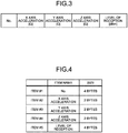
- FIG. 3 is a table illustrating an example of the format of the server 10a.
- FIG. 4 is a table illustrating an example of the format information representing the definition of the format of the server 10a illustrated in FIG. 3 .
- the server 10a is a server installed by the business A and is thus configured to be able to process sensor information transmitted from the device 30a installed by the business A.
- the sensor 31a of the device 30a is assumed to be a triaxial accelerometer and measures acceleration in each of X axis, Y axis, and Z axis directions.
- the device 30a measures the level of reception of a wireless signal transmitted through the wireless channel 40a.
- the device 30a transmits the acceleration in each of the X axis, Y axis, and Z axis directions and the level of reception as the sensor information in the format illustrated in FIG. 3 .
- the format of the server 10a is the same as the format of the sensor information transmitted from the device 30a, and is the format illustrated in FIG. 3 .
- the format of the server 10a includes "No.”, X axis acceleration [G], Y axis acceleration [G], Z axis acceleration [G], and the level of reception [dBm].
- the "No.” is a number associated with each sensor information and is determined by the device 30a, for example.
- the X axis, Y axis, and Z axis are also called “pitch axis", “roll axis”, and "yaw axis”.
- the format illustrated in FIG. 3 is defined by items from item #1 to item #5, where each item defines information indicating the name of the item, that is, the content of the item, and the size, that is, the data size of the item.
- Item #1 is an item indicating data stored at the head of the sensor information
- item #2 is an item indicating data stored next to item #1.
- the item numbers thus indicate the order of arrangement of the data in the format.
- the format of the server 10a and the format information in FIGS. 3 and 4 are illustrated as an example and are not limited thereto.
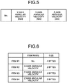
- FIG. 5 is a table illustrating an example of the format of the server 10c.
- FIG. 6 is a table illustrating an example of format information representing the definition of the format of the server 10c illustrated in FIG. 5 .
- the server 10c is a server installed by the business C and is thus configured to be able to process sensor information transmitted from the device 30c installed by the business C.
- the sensor 31c of the device 30c is assumed to be a gyro sensor and measures angular velocity in each of the X axis, Y axis, and Z axis directions, or angular velocity about each axis.
- the device 30c transmits the angular velocity in each of the X axis, Y axis, and Z axis directions as the sensor information in the format illustrated in FIG. 5 .
- the format of the server 10c is the same as the format of the sensor information transmitted from the device 30c, and is the format illustrated in FIG. 5 .
- the format of the server 10c includes "No.”, X axis angular velocity [degree per second (dps)], Y axis angular velocity [dps], and Z axis angular velocity [dps].
- the "No.” is a number associated with each sensor information.
- the format illustrated in FIG. 5 is defined by items from item #1 to item #4, where each item defines the name of the item and the size.
- the item numbers illustrated in FIG. 6 indicate the order of arrangement of the data in the format.
- the format of the server 10c and the format information in FIGS. 5 and 6 are illustrated as an example and are not limited thereto.
- the data processor 106 determines whether or not the sensor information received via the antenna 23, the wireless unit 22, and the driver group 103 can be transferred on the basis of the data processing policy for each server 10 to which the information is transferred, and at the same time determines whether or not the format of the sensor information needs to be converted. That is, the data processor 106 is a determination unit that determines, for each server 10, whether or not the second device information being the sensor information after subjected to the format conversion can be transferred to the server on the basis of the security setting of the communication path to the server 10.
- the gateway device 20 converts the format of single sensor information
- similar processing is performed to be able to convert the format by combining a plurality of sensor information received from a plurality of devices using the same wireless system or a plurality of sensor information collected from a plurality of devices using different wireless systems and transfer the information to the server 10.
- the format after combining the information is defined in the format information of the server 10 described above.
- the server 10a collects information combining both the sensor information transmitted from the device 30a and the sensor information transmitted from the device 30c
- the information transmitted to the server 10a has the format in which the format illustrated in FIG. 5 is added after the format illustrated in FIG. 3 .
- "No.” in the format illustrated in FIG. 3 and "No.” in the format illustrated in FIG. 5 may be left as is or may be deleted and replaced with a new number by the converter 105 so that "No.” indicating the new number may be included in the format.
- the security monitor 107 monitors the security setting status between the gateway device 20 and the server 10 and between the gateway device 20 and the management device 11. That is, the security monitor 107 monitors the security setting status of the communication path between the gateway device and each of the plurality of servers.
- the present embodiment describes an example of monitoring the status of establishment of IPsec as the security setting status.
- the protocol for ensuring security is not limited to the IPsec, and thus another security protocol can be used.
- the gateway device 20 may be configured to be able to perform processing using a plurality of security algorithms so that the security monitor 107 monitors the type of the security algorithm applied for each device.
- the storage 108 stores internal information necessary for the operation of the gateway device 20.
- the internal information necessary for the operation of the gateway device 20 includes operation information received from the management device 11 in a startup procedure described later.
- the power supply 109 has a function of supplying power from an external power supply including a system power supply to each unit in the gateway device 20, and can also supply power using power from a power generator such as a solar power generator in the event of a power failure of the external power supply.
- FIG. 7 is a diagram illustrating an example of the configuration of the management device 11 and the server 10 according to the present embodiment.
- the management device 11 includes a wired I/F 200, a device manager 201, a display 202, an input unit 203, a function update unit 204, a storage 205, and a power supply 206.
- the wired I/F 200 performs transmission/reception processing for connecting to the gateway device 20 via the Internet network 12.
- the wired I/F 200 receives information indicating the device status from the gateway device 20 and stores the information in the storage 205.
- the device manager 201 performs control to cause the display 202 to display the information indicating the device status of the gateway device 20 stored in the storage 205.
- the device manager 201 also manages operation information used to control the gateway device 20. Specifically, the device manager 201 reads the operation information which specifies the operation of each unit of the gateway device 20 from the storage 205, and notifies the device manager 104 in the gateway device 20 of the operation information via the wired I/F 200.
- the device manager 201 also registers, updates, and deletes the data processing policy used by the gateway device 20.
- the data processing policy is information indicating the definition of processing to be performed when the gateway device 20 receives the sensor information.
- the data processing policy includes an identification number of a device format, a transfer destination list, and the security evaluation policy for each reception path, or the wireless unit 22.
- the device format is the format of the sensor information transmitted from the device 30.
- the transfer destination list includes, for each transfer destination, information indicating a processing program to be executed when the sensor information is transferred. Details of the data processing policy will be described later.
- the display 202 displays the device status of the gateway device 20 managed by the device manager 201.
- the input unit 203 receives an input from an operator for setting the gateway device 20.
- the function update unit 204 transmits, to the gateway device 20, the processing program defined by the data processing policy corresponding to the new wireless unit 22 in response to a request from the gateway device 20.
- the processing program defined by the data processing policy is a processing program used to convert the format of the sensor information received from the device 30 into the format for transmission to the server 10, where the information indicating the processing program is included in a format conversion policy within the data processing policy.
- the function update unit 204 may download software for implementing the wireless unit 22 from the Internet network 12 and transmit the software to the gateway device 20 when a new wireless unit 22 is to be added to the gateway device 20.
- SDR Software Defined Radio
- VM Virtual Machine
- the processing program defined in the data processing policy may be a program of any format such as a plug-in program using Java (registered trademark) programming.
- the storage 205 stores internal information necessary for the operation of the management device 11 as well as device status information indicating the device status of the gateway device 20 and the operation information thereof that are managed by the device manager 201.
- the internal information necessary for the operation of the management device 11 and the operation information of the gateway device 20 are determined in advance, newly registered, or updated, for example, and are stored in the storage 205.
- the internal information necessary for the operation of the management device 11 and the operation information of the gateway device 20 may be changed on the basis of an external input through the input unit 203.
- the power supply 206 supplies power from an external power supply or the like to each unit of the management device 11.
- the server 10 is a device implemented by a general-purpose computer such as a personal computer.
- the server 10 includes a wired I/F 300, a device manager 301, a display 302, an input unit 303, an analysis unit 304, a storage 305, and a power supply 306.
- the wired I/F 300 performs transmission/reception processing based on the IP with the gateway device 20 via the Internet network 12.
- the device manager 301 and the analysis unit 304 are implemented by a processor of the computer reading and executing a program stored in a memory of the computer.
- the device manager 301 manages the device status including a software status on the server 10.
- the software status on the server 10 indicates the type of software usable on the server 10.
- the device status is similar to the device status of the gateway device 20.
- the display 302 can display the device status related to the server 10 managed by the device manager 301 and the sensor information collected via the gateway device 20 and the Internet network 12.
- the input unit 303 receives an input from an operator for operating the sensor information collected and setting the server 10.
- the analysis unit 304 analyzes the sensor information received from the gateway device 20 via the wired I/F 300, and stores the sensor information and a result of the analysis in the storage 305.
- the power supply 306 supplies power from an external power supply or the like to each unit of the server 10.
- the antenna 23 includes an antenna and a processing circuit which is an electronic circuit including a frequency converter circuit, an amplifier, and an analog-to-digital converter.
- the modem 101 includes a modem, and the wireless I/F 102 and the wired I/F 110 each include a communication interface circuit.
- the storage 108 is a memory.
- the power supply 109 is a power supply circuit that supplies power.
- the device manager 104, the converter 105, the data processor 106, and the security monitor 107 are implemented by a processing circuit which is an electronic circuit performing each processing.
- the processing circuit may be dedicated hardware or a control circuit including a memory and a central processing unit (also referred to as a CPU, a central processor, a processing unit, an arithmetic unit, a microprocessor, a microcomputer, a processor, or a digital signal processor (DSP)) that executes a program stored in the memory.
- a central processing unit also referred to as a CPU, a central processor, a processing unit, an arithmetic unit, a microprocessor, a microcomputer, a processor, or a digital signal processor (DSP)
- the memory corresponds to, for example, a non-volatile or volatile semiconductor memory such as a random access memory (RAM), a read only memory (ROM), a flash memory, an erasable programmable read only memory (EPROM), or an electrically erasable programmable read only memory (EEPROM), a magnetic disk, a flexible disk, an optical disk, a compact disc, a mini disc, or a digital versatile disk (DVD).
- RAM random access memory
- ROM read only memory
- EPROM erasable programmable read only memory
- EEPROM electrically erasable programmable read only memory
- the device manager 104, the converter 105, the data processor 106, and the security monitor 107 correspond to a single circuit, a complex circuit, a programmed processor, a parallel-programmed processor, an application specific integrated circuit (ASIC), a field programmable gate array (FPGA), or a combination of those, for example.
- ASIC application specific integrated circuit
- FPGA field programmable gate array
- the control circuit is a control circuit 400 configured as illustrated in FIG. 8 , for example.
- the control circuit 400 includes a processor 401 which is the CPU and a memory 402.
- the device manager, the converter, the data processor, and the security monitor are implemented by the processor 401 reading and executing a program corresponding to each processing stored in the memory 402.
- the memory 402 is also used as a temporary memory for each processing executed by the processor 401.
- the operation of the sensor monitoring system 500 of the present embodiment will now be described. First, there will be described the procedure from activation of the gateway device 20 and acquisition of the operation information from the management device 11 by the gateway device 20 up to the start of path monitoring between the gateway device 20 and the server 10, or the startup procedure of the gateway device 20.
- FIG. 9 is a sequence diagram illustrating an example of the startup procedure of the gateway device 20 according to the present embodiment.
- the gateway device 20 transmits an operation information acquisition request for acquiring the operation information used in the operation of the device to the management device 11, thereby acquiring the operation information.
- the gateway device first transmits, to the management device 11, the operation information acquisition request with "A" specified as a business identifier (ID) and "1" specified as a wireless ID, and acquires the operation information from the management device 11 (step S100).
- the business ID is identification information of the business, where "A" is the business ID of the business A, "B” is the business ID of the business B, and “C” is the business ID of the business C.
- the wireless ID is identification information of the wireless unit 22, where “1” is the wireless ID of the wireless unit 22a, "3” is the wireless ID of the wireless unit 22b, and "5" is the wireless ID of the wireless unit 22c.
- the device manager 104 of the gateway device 20 generates the operation information acquisition request including the wireless ID and the identifier of the business managing the corresponding device 30, and transmits the operation information acquisition request to the management device 11 via the wired I/F 110d.
- the storage 108 of the gateway device 20 is assumed to store the IP address of the management device 11 as the internal information, so that the device manager 104 reads the IP address of the management device 11 from the storage 108 and stores the IP address in the destination of an IP packet which is the operation information acquisition request.
- the IP packet is a packet in the format according to the IP.
- the IP address of the gateway device 20 itself stored in the storage 108 is stored as the source of the IP packet which is the operation information acquisition request transmitted from the gateway device 20.
- the IP address of the gateway device 20 need not be predetermined but may be assigned by the management device 11 or another device. In this case, processing for acquiring the IP address is executed according to the IP prior to the transmission of the operation information acquisition request.
- the management device 11 Upon receiving the operation information acquisition request from the gateway device 20, the management device 11 reads the operation information related to the management business identifier and the wireless ID from the operation information of the gateway device 20 stored in the storage 205, and distributes or transmits the operation information to the gateway device 20. Specifically, upon receiving the operation information acquisition request from the gateway device 20 via the wired I/F 200, the device manager 201 of the management device 11 reads the operation information corresponding to the wireless unit 22 of the gateway device 20 from the storage 205 and transmits the operation information being read to the gateway device 20 via the wired I/F 200.
- the device manager 201 detecting that a new wireless unit 22 is added to the gateway device 20 notifies the function update unit 204 about the addition of the wireless unit 22, so that the function update unit 204 retrieves the operation information from the storage 205 and transmits the operation information to the gateway device 20 via the device manager 201.
- the storage 205 stores a data processing program for format conversion
- the data processing program in the executable format is downloaded to the gateway device 20, or transmitted to the gateway device 20 via the wired I/F 200.
- a general-purpose data transfer protocol such as File Transfer Protocol (FTP) can be used as the communication protocol in this case, and the communication protocol such as Hypertext Transfer Protocol (HTTP) may be used when the data processing program is implemented in the plug-in format using Java or the like.
- FTP File Transfer Protocol
- HTTP Hypertext Transfer Protocol
- the gateway device 20 transmits to the management device 11 an operation information acquisition request with "B" specified as the business ID and "3" specified as the wireless ID to acquire the operation information, and transmits to the management device 11 an operation information acquisition request with "C” specified as the business ID and "5" specified as the wireless ID to acquire the operation information (step S101).
- the correspondence between the wireless ID and the business ID is preset in the gateway device 20. Alternatively, the correspondence between the wireless ID and the business ID may be input by an operator.
- the operation information distributed to the gateway device 20 by the management device 11 includes frequency information indicating a frequency band used for the wireless signal transmitted and received by the wireless unit 22, transmission power information indicating transmission power when the wireless unit 22 of the gateway device 20 transmits the wireless signal, security setting when connection is established with the server as a host device, information on a path monitoring method using Ping or Stream Control Transmission Protocol (SCTP), information on the data processing policy, and the like.
- frequency information indicating a frequency band used for the wireless signal transmitted and received by the wireless unit 22
- transmission power information indicating transmission power when the wireless unit 22 of the gateway device 20 transmits the wireless signal
- security setting when connection is established with the server as a host device information on a path monitoring method using Ping or Stream Control Transmission Protocol (SCTP), information on the data processing policy, and the like.
- SCTP Stream Control Transmission Protocol
- FIG. 10 is a table illustrating an example of the data processing policy included in the operational information distributed to the gateway device 20 by the management device 11.
- the data processing policy includes a reception path, a device number, that is, the identification number of the device format, the transfer destination list, and the security evaluation policy.
- the reception path indicates the wireless ID of the wireless unit 22 receiving the sensor information of the device 30, and the device format indicates the identifier specifying the format of the sensor information received by the wireless unit 22.
- the formats illustrated in FIGS. 3 and 5 as described above can be used as the device format, for example. Note that the identifier is assigned in advance to each device format.
- the transfer destination list includes a transfer destination address, a conversion format, and processing, that is, information on the processing program to be executed, for each transfer destination.
- the transfer destination is the server 10 to which the sensor information is transferred from the gateway device 20.
- a transfer destination #1 which is the first transfer destination on the transfer destination list in each reception path is the server of the business installing the device 30 corresponding to the reception path.
- the server 10 corresponding to the transfer destination #1 is installed by the same business as the business installing the device 30 corresponding to the reception path.
- the server 10 of the same business as the business installing the device 30 is also referred to as a server of one's own business.
- the security evaluation policy is information indicating the correspondence between the security setting status between the gateway device 20 and the server 10 and whether the information can be transferred to the server of another business, that is, a business different from the business installing the device.
- the example illustrated in FIG. 10 assumes the application of the IPsec as the security protocol where, for all the reception paths, the security evaluation policy is so set that the information can be transferred only when security is set with the server 10 of another business. Note that in FIG. 10 , the policy that the information can be transferred only when security is set with the server 10 of another business is abbreviated as "transferable only when set".
- the policy that the information can be transferred only when security is set with the server 10 of another business means that, in the case where the server 10 of another business is the transfer destination, the sensor information can be transferred thereto when security is set with the server 10, that is, when the IPsec is already established therewith, and the sensor information is not allowed to be transferred when security is not set with the server 10.
- the ID of the device instead of the wireless ID may be used as the reception path when the sensor information is received from devices installed by a plurality of businesses through one reception path.
- the data processing policy is updated each time a new server 10 or reception path is added to the sensor monitoring system 500.
- the processing program for converting the format is downloaded from the management device 11 to the gateway device 20 as described above.
- the executable format of the processing program may be a library format or a plug-in format using Java. The present embodiment assumes that the executable format of the processing program is the library format.
- the device manager 104 of the gateway device 20 applies the operation information received (step S102). For example, the device manager 104 performs settings such as setting the frequency band and the transmission power of the wireless I/F 102 on the basis of the frequency information and the transmission power information included in the operation information.
- the device manager 104 of the gateway device 20 performs security setting on the corresponding wired I/F 110 on the basis of the security procedure indicated by the operation information.
- the operation information is assumed to indicate that security setting is to be performed with the server 10a and the server 10c, so that the wired I/F 110a of the gateway device 20 first performs security setting with the server 10a on the basis of the security procedure indicated in the operation information (step S103).
- the security setting is performed on the basis of a procedure such as Internet Key Exchange Protocol Version 2 (IKEv2) to establish an IPsec security association.
- IKEv2 Internet Key Exchange Protocol Version 2
- the wired I/F 110a Upon completion of the security setting, the wired I/F 110a notifies the security monitor 107 that the security setting of the path to the server 10a is done. Note that when the security setting of the path to the server 10a is canceled, the wired I/F 110a notifies the security monitor 107 accordingly.
- the wired I/F 110a When path monitoring is requested in the operation information, the wired I/F 110a starts transmission/reception of a path monitoring request and a path monitoring response for the purpose of health check (step S104).
- the present embodiment assumes the health check using Ping as the path monitoring method, but the present invention is not limited thereto.
- the wired I/F 110c of the gateway device 20 performs security setting with the server 10c on the basis of the security procedure indicated in the operation information (step S105), and starts transmission/reception of a path monitoring request and a path monitoring response for the purpose of health check (step S106) when path monitoring is requested in the operation information.
- the wired I/F 110c Upon completion of the security setting, the wired I/F 110c notifies the security monitor 107 that the security setting of the path to the server 10c is done.
- the wired I/F 110c notifies the security monitor 107 accordingly.
- the security monitor 107 monitors the security setting status with each server 10 on the basis of the notification from each wired I/F 110.
- FIG. 11 is a flowchart illustrating an example of a sensor information transfer procedure of the gateway device 20.
- the data processor 106 of the gateway device 20 determines whether or not the sensor information transmitted from the device 30 is received (step S1). Note that the wireless unit 22 receives the sensor information via the antenna 23 and passes the sensor information to the data processor 106 via the driver group 103. At this time, the driver group 103 determines the wireless unit 22 receiving the sensor information, and passes the wireless ID corresponding to the wireless unit 22 to the data processor 106 together with the sensor information. Step S1 is repeated if no sensor information is received (No in step S1).
- the data processor 106 determines the reception path through which the sensor information is received (step S2). Specifically, the data processor 106 determines the reception path on the basis of the wireless ID received together with the sensor information. Next, the data processor 106 determines the transfer destination of the sensor information on the basis of the data processing policy in the operation information stored in the storage 108 and the reception path (step S3).
- the data processor 106 selects one of the transfer destinations determined in step S3, and determines whether or not the source, that is, the device 30 from which the sensor information is transmitted, and the transfer destination are of the same business (step S4).
- the transfer destination #1 is the transfer destination of one's own business, that is, the device 30 being the source and the transfer destination are of the same business, whereby the data processor 106 determines that the source and the transfer destination are of the same business when the selected transfer destination is the transfer destination #1, or determines that the source and the transfer destination are not of the same business when the selected transfer destination is the transfer destination #2 or a subsequent destination.
- step S4 the data processor 106 transfers the sensor information to the selected transfer destination via the driver group 103 and the wired I/F 110 as the second communication unit (step S5). At this time, the sensor information is transmitted while stored in the IP packet in the wired I/F 110.
- the data processor 106 determines whether or not transfer to all the transfer destinations, that is, all the transfer destinations included in the transfer destination list of the data processing policy, is completed (step S6), and returns to step S1 if the transfer to all the transfer destinations is completed (Yes in step S6).
- step S6 If the transfer to any of the transfer destinations is not completed (No in step S6), the data processor 106 changes the transfer destination selected and returns to step S4. If the source and the transfer destination are not of the same business (No in step S4), the data processor 106 performs a security evaluation (step S7). Specifically, the data processor 106 acquires the security setting status corresponding to the selected transfer destination from the security monitor 107. Then, on the basis of the security setting status and the security evaluation policy in the data processing policy, the data processor 106 determines whether or not the sensor information can be transferred to the selected transfer destination (step S8). If the sensor information can be transferred (Yes in step S8), the data processor 106 performs format conversion on the basis of the data processing policy (step S9) and proceeds to step S5.
- a security evaluation step S7. Specifically, the data processor 106 acquires the security setting status corresponding to the selected transfer destination from the security monitor 107. Then, on the basis of the security setting status and the security evaluation policy in the data processing policy, the data processor
- step S5 the second communication unit transmits the second device information which is the information after subjected to the conversion to the server to which the information is determined to be transferable by the data processor 106.
- step S9 the data processor 106 performs the format conversion by causing the converter 105 to execute the program specified by the processing on the transfer destination list in the data processing policy. If the sensor information cannot be transferred (No in step S8), the data processor 106 does not transfer the sensor information to the selected transfer destination, changes the transfer destination selected, and returns to step S4.
- FIG. 12 is a sequence diagram illustrating an example of data processing of the gateway device 20 when security is applied.
- the security between the gateway device 20 and each of the server 10a and the server 10c is already set, and the security monitor 107 of the gateway device 20 recognizes that the security between the gateway device and each of the server 10a and the server 10c is already set.
- the gateway device 20 is assumed to have received the data processing policy illustrated in FIG. 10 from the management device 11.
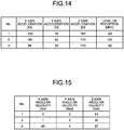
- FIG. 14 is a table illustrating an example of the sensor information A. As illustrated in FIG. 14 , the sensor information A has the device format similar to the format illustrated in FIG. 3 .
- the data processor 106 performs security evaluation processing on the server 10c corresponding to the transfer destination #3 in the data processing policy (step S201). Since the security is already set with the server 10c, the data processor 106 determines that information can be transferred thereto and causes the converter 105 to execute program 5 to perform conversion processing, that is, format conversion (step S202), thereby transferring sensor information C (converted) being the sensor information after subjected to the format conversion to the server 10c via the wired I/F 110c (step S203).
- the server 10c can thus read and use the sensor information transmitted from the device 30a by the processing similar to the processing at the time of reading the sensor information transmitted from the device 30c installed by one's own business.
- FIG. 15 is a table illustrating an example of the sensor information C. As illustrated in FIG. 15 , the sensor information C has the device format similar to the format illustrated in FIG. 5 .
- the data processor 106 performs security evaluation processing on the server 10a corresponding to the transfer destination #2 in the data processing policy (step S205). Since the security is already set with the server 10a, the data processor 106 determines that information can be transferred thereto and causes the converter 105 to execute program 1 to perform conversion processing, that is, format conversion (step S206), thereby transferring sensor information A (converted) being the sensor information after subjected to the format conversion to the server 10a via the wired I/F 110a (step S207).
- the server 10a can thus read and use the sensor information transmitted from the device 30c by the processing similar to the processing at the time of reading the sensor information transmitted from the device 30a installed by one's own business. Note that although FIG. 12 omits the transfer processing between the gateway device 20 and the server 10b, the transfer processing for the server 10b is performed similarly on the basis of the data processing policy.
- the wired I/F 110 as the second communication unit transmits the first device information to a predetermined specific server associated with each device among the plurality of servers 10, and transmits the second device information being the information after subjected to the format conversion to the plurality of servers other than the specific server when the data processor 106 determines that information can be transferred to the servers.
- a predetermined specific server associated with each device among the plurality of servers 10
- An example of the specific server is the server installed by the same business as the business installing the device 30, as described above.
- FIG. 13 is a sequence diagram illustrating an example of data processing of the gateway device when security is not set.
- FIG. 13 illustrates an example in which security between the gateway device 20 and the server 10a is already set while security between the gateway device 20 and the server 10c is not set.
- the data processor 106 of the gateway device 20 Upon receiving the sensor information A transmitted from the device 30a via the antenna 23a and the wireless unit 22a of the gateway device 20 in such state, the data processor 106 of the gateway device 20 transfers the sensor information A to the server 10a corresponding to the transfer destination #1 in the data processing policy as with step S200 of FIG. 12 (step S301).
- the data processor 106 performs security evaluation processing on the server 10c corresponding to the transfer destination #3 in the data processing policy (step S302). Since security is not set with the server 10c, the data processor 106 determines that information cannot be transferred thereto and does not transfer the information to the server 10c.
- the data processor 106 of the gateway device 20 Upon receiving the sensor information C transmitted from the device 30c via the antenna 23c and the wireless unit 22c of the gateway device 20, the data processor 106 of the gateway device 20 transfers the sensor information C to the server 10c corresponding to the transfer destination #1 in the data processing policy on the basis of the data processing policy (step S303). Although security is not set with the server 10c, the information is transferred thereto when the transfer destination is of one's own business. Steps S304 to S306 are similar to steps S205 to S207 in FIG. 12 . Note that although FIG. 13 omits the transfer processing between the gateway device 20 and the server 10b, the transfer processing for the server 10b is performed similarly on the basis of the data processing policy.
- FIG. 16 is a sequence diagram illustrating another example of data processing of the gateway device when security is not set. Instead of the examples illustrated in FIGS. 3, 4 , 5, and 6 , the sequence diagram illustrated in FIG. 16 is based on formats and definitions of the formats illustrated in FIGS. 17 , 18 , 19 , and 20 and a data processing policy illustrated in FIG. 21 .
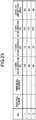
- the device format is based on device formats illustrated in FIGS. 22 and 23 .
- FIG. 17 is a table illustrating an example of the format of the server 10a
- FIG. 18 is a table illustrating the definition of the format illustrated in FIG. 17
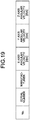
- FIG. 19 is a table illustrating an example of the format of the server 10c
- FIG. 20 is a table illustrating the definition of the format illustrated in FIG. 19 .
- information indicating the manufacturer of the device 30a and an individual number are added to the format in contrast to the examples illustrated in FIGS. 3 and 4 .
- FIGS. 19 and 20 information indicating the manufacturer of the device 30c and an individual number such as a serial number are added to the format in contrast to the examples illustrated in FIGS. 5 and 6
- FIG. 21 is a table illustrating an example of the data processing policy assuming the formats illustrated in FIGS. 17 , 18 , 19 , and 20 .
- the security evaluation policy is modified from that of the data processing policy illustrated in FIG. 10 , but the rest is similar to the example illustrated in FIG. 10 .
- a secret level is preset for each item in the device format so that the security evaluation policy indicates whether or not data of each item can be transferred in accordance with the secret level.
- the information indicating the manufacturer and an individual number are defined as individual information while the other items are defined as detected information.
- the individual information is set to secret level 2, and the detected information is set to secret level 1.
- the security evaluation policy is so set that information of secret level 2 or higher is untransferable as illustrated in FIG. 21
- the individual information is untransferable while the detected information is transferable when security is not set.
- all items of the sensor information is transferable when security is already set.
- the security evaluation policy is so set that all is transferable, all the items of the sensor information is transferable even when security is not set.
- FIG. 22 is a table illustrating the device format of the device 30a.
- FIG. 23 is a table illustrating the format of the sensor information when the sensor information of the device 30a is transferred to the server 10c. As illustrated in FIG. 22 and FIG. 23 , the individual information is deleted when the sensor information of the device 30a is transferred to the server 10c.
- the information making up the sensor information which is the first device information is classified into a plurality of levels, that is, secret levels, and the security evaluation policy which is a condition for determining whether or not information can be transferred to the server is set for each level.
- the data processor 106 determines whether or not to transfer the information making up the sensor information to the server for each level on the basis of the security evaluation policy, and the converter 105 converts, for each server 10, the information of the level determined to be transferable by the data processor 106 among the sensor information into the second device information.
- FIG. 16 illustrates an example in which security between the gateway device 20 and the server 10a is already set while security between the gateway device 20 and the server 10c is not set.
- the data processor 106 of the gateway device 20 Upon receiving the sensor information A transmitted from the device 30a via the antenna 23a and the wireless unit 22a of the gateway device 20 in such state, the data processor 106 of the gateway device 20 transfers the sensor information A to the server 10a corresponding to the transfer destination #1 in the data processing policy (step S400).
- the data processor 106 performs security evaluation processing on the server 10c corresponding to the transfer destination #3 in the data processing policy (step S401). With security not being set with the server 10c and the security evaluation policy not allowing transfer of information that is secret level 2 or higher, the individual information in the sensor information A is invalidated, the converter 105 executes program 5 to perform conversion processing, that is, format conversion (step S402), and sensor information C (converted) which is the sensor information after subjected to the format conversion is transferred to the server 10c via the wired I/F 110c (step S403).
- the individual information can be invalidated by a method that replaces the individual information with a fixed value such as all zeros, for example.
- the transmission of the detected information without the individual information as described above allows the detected information to be shared among a plurality of servers while preventing a malicious attack on the device 30.
- the gateway device 20 is provided with the converter 105 that performs the format conversion required for each destination server and the security monitor 107 that monitors the security set with the server 10, thereby determining the transfer destination on the basis of the security setting information.
- the server 10 can thus use the sensor information of the device 30 managed by another business without changing the setting of the server 10. That is, a plurality of servers can share the information of the device 30 while ensuring security.
- the server not knowing the wireless system and the sensor type of each device can be provided with the information transmitted from the device installed by another business.
- FIG. 24 is a diagram illustrating an example of the configuration of a sensor monitoring system according to a second embodiment of the present invention.
- a sensor monitoring system 501 of the second embodiment which is the monitoring system according to the present invention is similar to the sensor monitoring system 500 of the first embodiment except that a gateway device 60 and access points 25a, 25b, and 25c as communication devices are included instead of the gateway device 20 of the sensor monitoring system 500 of the first embodiment.
- a component having a function similar to that of the first embodiment will be assigned a reference numeral identical to that assigned to the component in the first embodiment so that a redundant description will be omitted. Differences from the first embodiment will be described below.
- the first embodiment includes the wireless unit 22 in the gateway device 20, whereas the present embodiment includes the wireless units 22a, 22b, and 22c in the access points (hereinafter abbreviated as APs) 25a, 25b, and 25c transmitting and receiving wireless signals through the wireless channels 40a, 40b, and 40c, respectively.
- the APs 25a, 25b, and 25c also include the antennas 23a, 23b, and 23c, respectively.
- the wireless units 22a, 22b, and 22c perform wireless communication with the devices 30a, 30b, and 30c via the antennas 23a, 23b, and 23c, respectively.
- the APs 25a, 25b, and 25c further include wired units 24a, 24b, and 24c, respectively.
- the wired units 24a, 24b, and 24c are connected to the Internet network 12 and transmit signals received by the corresponding wireless units 22a, 22b, and 22c as IP packets to the gateway device 60 via the Internet network 12.
- the gateway device 60 transfers sensor information received as the IP packets from the wired units 24a, 24b, and 24c to the servers 10 on the basis of the data processing policy as in the first embodiment.
- FIG. 25 is a diagram illustrating an example of the configuration of the gateway device 60.
- the gateway device 60 is similar to the gateway device 20 of the first embodiment except that wired I/Fs 120a, 120b, and 120c are included instead of the wireless units 22a, 22b, and 22c and the antennas 23a, 23b, and 23c. Note that illustration of the wired I/F 120b is omitted.
- the wired I/Fs 120a, 120b, and 120c output the sensor information received as the IP packets from the corresponding APs 25a, 25b, and 25c to the data processor 106.
- the IP packet includes the IP address of the source AP 25, or the wired unit of the AP 25.
- connection between the wired I/F 120 and the AP 25 assumes transmission/reception processing using the IP, but a communication protocol such as Point to Point Protocol over Ethernet (PPPoE) may be used.
- PPPoE Point to Point Protocol over Ethernet
- one wired I/F 120 is provided for each AP 25, the wired I/F 120 can be shared.
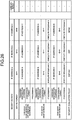
- FIG. 26 is a table illustrating an example of the data processing policy according to the present embodiment.
- the present embodiment uses the IP addresses of the wired units 24, 24b, and 24c as the identifier of the reception path to be able to determine the reception path as the first embodiment does.
- the security evaluation policy in FIG. 26 illustrates an example in which a determination is made on the basis of the status of application of the security algorithm, but the security evaluation policy similar to the security evaluation policy of the first embodiment may be used. The example illustrated in FIG.
- the server 10 can use the sensor information of the device 30 managed by another business without changing the setting of the server 10, as with the first embodiment. That is, a plurality of servers can share the information of the device while ensuring security. Moreover, the server not knowing the wireless system and the sensor type of each device can be provided with the information transmitted from the device installed by another business.
Landscapes
- Engineering & Computer Science (AREA)
- Computer Security & Cryptography (AREA)
- Computer Networks & Wireless Communication (AREA)
- Signal Processing (AREA)
- Computer Hardware Design (AREA)
- Computing Systems (AREA)
- General Engineering & Computer Science (AREA)
- Data Exchanges In Wide-Area Networks (AREA)
- Computer And Data Communications (AREA)
Description
- The present invention relates to a gateway device and a transfer method for collecting information from a plurality of devices that perform communication using different communication systems.
- As an enormous number of various devices such as devices with sensors, cameras, vehicles, and household appliances are connected to the Internet in recent years, people have expectations for an Internet of Things (IoT) technology that collects information from the devices and creates new value. One example of the IoT technology is a sensor monitoring system that uses sensors to monitor infrastructure such as roads, tunnels, and bridges. The proportion of the infrastructure such as the roads, tunnels, and bridges constructed 50 or more years ago is expected to increase rapidly in the next 20 years. Installing devices with sensors at the infrastructure facilities such as the roads, tunnels, and bridges and collecting information from the devices are thought to allow for efficient operation and management of the facilities and efficient updates of a deteriorating facility on the basis of the information collected.
- On the other hand, the devices with sensors use various wireless systems. For example, the devices can use a system based on the Institute of Electrical and Electronic Engineers (IEEE) 802.15.4 standard such as Zigbee (registered trademark) or Wireless Smart Utility Network (Wi-SUN) (registered trademark) which is a short-range wireless communication standard for a smart meter or the like, and also a new wireless system such as Narrowband IoT standardized by Rel. 13 of the 3rd Generation Partnership Project (3GPP) and IEEE 802.11ah which is one of the Wi-Fi (registered trademark) standards. Moreover, the sensors include various kinds of sensors such as a thermometer, an accelerometer, and a watt-hour meter.
- The sensor monitoring system utilizing the IoT is therefore required to be compatible with various sensors and wireless systems, or to be able to process information acquired by various kinds of sensors and at the same time perform reception processing corresponding to various wireless systems.
- As a technique for supporting various sensors and wireless systems,
Patent Literature 1 discloses a technique for facilitating addition of a new kind of sensor and introduction of a new communication standard by converting the format of data collected from sensor nodes into the format that is easy to handle before a server as a host device performs processing. -
Patent Literature 2 describes a method and program product for securely routing communicating data between sources and destinations having various data protocols. Data protocols are converted to internet protocol, if not already in internet protocol, for routing. Cryptographic keys of the source, the message, and the destination are verified. If a source and a destination share the same control system, the communication need not, but may, be encrypted for routing; otherwise, the communication is encrypted for routing on the local area network and then decrypted before transmission to the destination. Some communications require further security processing, such as in a HAIPE for certain SATCOM communications. -
Patent Literature 3 describes a multi-level security data processing architecture which includes various components configured to provide full data separation across multiple processors while limiting the number and size of high assurance components. The architecture includes a domain separator for ensuring that messages exchanged between domains that are distributed on different microprocessors are securely routed between domain members. The domain separator verifies a message label including a domain identifier provided by a domain gateway and cryptographically binds the message label to each message via cryptographic keys. -
Non-Patent Literature 1 describes a method for transforming a Session Initiation Protocol (SIP) message to a Simple Object Access Protocol (SOAP) message. -
Patent Literature 4 describes a method for distributing a single stream of sensor data to one or more services. The method may include maintaining an association between sensor data and one or more services requesting the sensor data. -
- Patent Literature 1:
JP 4719034 B2 - Patent Literature 2:
US 8 220 038 B1 - Patent Literature 3:
EP 2 428 910 A2 - Patent Literature 4:
US 2014/140254 A1 - Non-Patent Literature 1 : DAN YAMAMOTO ET AL, "A Study on High- Performance Presence Monitoring System", IEICE TECHNICAL REPORT TM2007-65,, (20080306), vol. 107, no. 545, pages 73 - 78, XP009510265
- Installing a huge number of devices requires a great deal of labor so that installing a device for each different business leads to an increase in cost and maintenance. Thus, in the sensor monitoring system utilizing IoT, sharing information of a device, that is, the information acquired by the device, becomes an issue. Although the information of the device can be shared among servers of businesses, the information transmission among the servers lacks immediacy and is thus difficult to apply to an application requiring low latency. On the other hand, ensuring security in IoT is also an important issue. Sharing individual information of a device or the like in a network where security is not ensured may encourage a malicious attack on the device.
- The technique described in
Patent Literature 1 above can collect information of a device without the server performing processing corresponding to the wireless system and the kind of the sensor when there is only one server.Patent Literature 1 however does not describe a method of sharing the information of the device among a plurality of servers of different businesses. The paths between a gateway device and the plurality of servers managed by the different businesses may have different levels of security so that, in terms of ensuring security, there may be a problem with the gateway device simply transferring information therefrom to the plurality of servers. - The present invention has been made in view of the above, and an object of the present invention is to obtain a gateway device that allows a plurality of servers to share device information while ensuring security.
- The above problems are solved by the subject-matter according to the independent claims.
- The gateway device according to the present invention has an effect of allowing the plurality of servers to share the device information while ensuring security.
-
-
FIG. 1 is a diagram illustrating an example of the configuration of a sensor monitoring system according to a first embodiment. -
FIG. 2 is a diagram illustrating an example of the configuration of a gateway device according to the first embodiment. -
FIG. 3 is a table illustrating an example of the format of a server according to the first embodiment. -
FIG. 4 is a table illustrating an example of format information representing the definition of the format of the server illustrated inFIG. 3 . -
FIG. 5 is a table illustrating an example of the format of the server according to the first embodiment. -
FIG. 6 is a table illustrating an example of format information representing the definition of the format of the server illustrated inFIG. 5 . -
FIG. 7 is a diagram illustrating an example of the configuration of a management device and the server according to the first embodiment. -
FIG. 8 is a diagram illustrating an example of the configuration of a control circuit according to the first embodiment. -
FIG. 9 is a sequence diagram illustrating an example of a startup procedure of the gateway device according to the first embodiment. -
FIG. 10 is a table illustrating an example of a data processing policy according to the first embodiment. -
FIG. 11 is a flowchart illustrating an example of a sensor information transfer procedure of the gateway device according to the first embodiment. -
FIG. 12 is a sequence diagram illustrating an example of data processing of the gateway device when security is applied according to the first embodiment. -
FIG. 13 is a sequence diagram illustrating an example of data processing of the gateway device when security is not set according to the first embodiment. -
FIG. 14 is a table illustrating an example of sensor information A according to the first embodiment. -
FIG. 15 is a table illustrating an example of sensor information C according to the first embodiment. -
FIG. 16 is a sequence diagram illustrating another example of data processing of the gateway device when security is not set according to the first embodiment. -
FIG. 17 is a table illustrating an example of the format of the server according to the first embodiment. -
FIG. 18 is a table illustrating the definition of the format illustrated inFIG. 17 according to the first embodiment. -
FIG. 19 is a table illustrating an example of the format of the server according to the first embodiment. -
FIG. 20 is a table illustrating the definition of the format illustrated inFIG. 19 . -
FIG. 21 is a table illustrating an example of the data processing policy assuming the formats illustrated inFIGS. 17 ,18 ,19 , and20 . -
FIG. 22 is a table illustrating the device format of a device according to the first embodiment. -
FIG. 23 is a table illustrating the format of the sensor information according to the first embodiment. -
FIG. 24 is a diagram illustrating an example of the configuration of a sensor monitoring system according to a second embodiment. -
FIG. 25 is a diagram illustrating an example of the configuration of a gateway device according to the second embodiment. -
FIG. 26 is a table illustrating an example of a data processing policy according to the second embodiment. - A gateway device and a transfer method according to an embodiment of the present invention will now be described in detail with reference to the drawings. Note that the present invention is not limited to the embodiment.
-
FIG. 1 is a diagram illustrating an example of the configuration of a sensor monitoring system according to a first embodiment of the present invention. As illustrated inFIG. 1 , asensor monitoring system 500 of the first embodiment which is a monitoring system according to the present invention includesservers gateway device 20, amanagement device 11, anddevices servers servers servers FIG. 1 illustrates three of the plurality of servers, any number of servers may be installed. - The
gateway device 20 is connected to anInternet network 12 and can communicate with each of theservers management device 11 via theInternet network 12 using an Internet Protocol (IP). The present embodiment will describe an example of using the IP as a communication protocol for the communication between thegateway device 20 and each of theservers management device 11, but the communication protocol used for the communication between thegateway device 20 and each of theservers management device 11 is not limited to the IP. Thegateway device 20 can also perform wireless communication with each of thedevices - The
devices devices devices device 30a includes asensor 31a, awireless unit 32a, and anantenna 33a, thedevice 30b includes asensor 31b, awireless unit 32b, and anantenna 33b, and thedevice 30c includes asensor 31c, awireless unit 32c, and anantenna 33c. The communication system used by thedevice 30a is also referred to as a first communication system, the communication system used by thedevice 30b is also referred to as a second communication system, and the communication system used by thedevice 30c is also referred to as a third communication system. The present embodiment uses an acceleration sensor and a gyro sensor (an angular velocity sensor) as examples of thesensors FIG. 1 illustrates the antennas outside of the corresponding blocks in order to emphasize propagation of a wireless signal from the antennas, each antenna may be mounted on the device on which the wireless unit connected to the antenna is mounted. - The
sensor monitoring system 500 supports the wireless systems used by thedevices gateway device 20 of thesensor monitoring system 500 can perform communication using the first communication system, the second communication system, and the third communication system which are a plurality of wireless communication systems. The wireless systems supported by thesensor monitoring system 500 can be added or deleted. The communication standards such as Wi-SUN, Zigbee, and Narrowband IoT defined by the 3GPP correspond to the wireless systems used by thedevices sensor monitoring system 500. However, the wireless systems supported by thesensor monitoring system 500 of the present embodiment are not limited thereto. Moreover, although an example in which one device supports one wireless system is described herein, one device may support a plurality of wireless systems, or a plurality of devices may support a single wireless system. - The
management device 11 monitors the setting and operating state of thegateway device 20 and, when thesensor monitoring system 500 supports a new wireless system, downloads a program for supporting the new wireless system. -
FIG. 1 illustrates an example of the configuration in which themanagement device 11 is connected to onegateway device 20, but two or more of thegateway devices 20 may be connected to themanagement device 11. Moreover, on the basis of security evaluation policies of the businesses, a protocol such as Internet Protocol Security (IPsec) may be applied between one or more of theservers gateway device 20 in order to enhance the security of the communication path between theservers gateway device 20. Furthermore, althoughFIG. 1 illustrates theInternet network 12 as one network, one or more of theservers gateway device 20 via a closed communication network formed by the business(es). - The
gateway device 20 includes agateway unit 21 that implements a function as a gateway including sensor information sharing processing,wireless units antennas wireless unit 22a and theantenna 23a are a wireless unit and an antenna compatible with the first communication system, thewireless unit 22b and theantenna 23b are a wireless unit and an antenna compatible with the second communication system, and thewireless unit 22c and theantenna 23c are a wireless unit and an antenna compatible with the third communication system. That is, thegateway device 20 can wirelessly communicate with thedevice 30a via thewireless unit 22a and theantenna 23a, wirelessly communicate with thedevice 30b via thewireless unit 22b and theantenna 23b, and wirelessly communicate with thedevice 30c via thewireless unit 22c and theantenna 23c. -
Service areas FIG. 1 indicate ranges in which the devices can communicate with thewireless units gateway device 20, respectively. That is, theservice area 50a is a range in which thewireless unit 22a of thegateway device 20 and thewireless unit 32a of thedevice 30a can communicate with each other via theantenna 23a and theantenna 33a through awireless channel 40a. Thewireless channel 40a indicates a wireless channel based on the first communication system. Likewise, theservice area 50b is a range in which thewireless unit 22b of thegateway device 20 and thewireless unit 32b of thedevice 30b can communicate with each other via theantenna 23b and theantenna 33b through awireless channel 40b. Thewireless channel 40b indicates a wireless channel based on the second communication system. Likewise, theservice area 50c is a range in which thewireless unit 22c of thegateway device 20 and thewireless unit 32c of thedevice 30c can communicate with each other via theantenna 23c and theantenna 33c through awireless channel 40c. Thewireless channel 40c indicates a wireless channel based on the third communication system. - The
wireless units - In the following description, the
servers server 10 as appropriate when no distinction is made thereamong. Likewise, thedevices device 30 as appropriate when no distinction is made thereamong, and thewireless channels sensors wireless units wireless units wireless unit 22 as appropriate when no distinction is made thereamong. Theantennas service areas FIG. 1 illustrates three of thedevices 30, the number of devices is not limited thereto but may be one or more. - In the
sensor monitoring system 500 of the present embodiment, theserver 10 collects sensor information as the first device information from thedevice 30 through wireless communication via theInternet network 12, thegateway device 20, and the wireless channel 40. The sensor information includes information indicating a result detected by the sensor 31 of thedevice 30, or information acquired by the sensor 31. Note that in the following example, a device equipped with a sensor is described as the device transmitting the information collected by theserver 10. However, the device is not limited to the device equipped with a sensor but may be a household appliance, a camera, or the like with a wireless communication function. That is, the information collected by theserver 10 may be device information transmitted from the device, and the sensor information is an example of device information. - As illustrated in
FIG. 1 , thegateway device 20 transmits and receives radio waves using the wireless channel 40 corresponding to each wireless system, and the service area 50 is configured by the radio waves. On thegateway device 20, thegateway unit 21 controls eachwireless unit 22. Each service area 50 can also be referred to as a range capable of receiving the radio waves emitted from the antenna 23 connected to thewireless unit 22 of thegateway device 20. Each service area 50 can flexibly change the point where the radio waves are actually transmitted and received by thegateway device 20 by extending the antenna 23. The service areas 50 may thus overlap or may be configured individually without overlapping. Note that the plurality of wireless systems supported by thesensor monitoring system 500 may be wireless systems with a plurality thereof using the same frequency, or may be wireless systems each using a different frequency. Each wireless system uses a different frequency in the following example describing thesensor monitoring system 500 of the present embodiment below, but the frequency used by the wireless system is not limited thereto. -
FIG. 2 is a diagram illustrating an example of the configuration of thegateway device 20 according to the embodiment.FIG. 2 includes illustration of thedevice 30, theserver 10a, theserver 10c, themanagement device 11, and theInternet network 12. As illustrated inFIG. 2 , thegateway unit 21 of thegateway device 20 includes adriver group 103, adevice manager 104, aconverter 105, adata processor 106, asecurity monitor 107, astorage 108, apower supply 109, and wired interfaces (I/F) 110a, 110c, and 110d. - The wired I/
F 110a communicates with theserver 10a via theInternet network 12. A wired I/F 110b communicates with the server 10b via theInternet network 12. The wired I/F 110c communicates with theserver 10c via theInternet network 12. The wired I/F 110d communicates with themanagement device 11 via theInternet network 12.FIG. 2 omits illustration of the wired I/F 110b and the server 10b. AlthoughFIG. 2 illustrates an example in which thegateway device 20 includes the wired I/F 110 for each of theservers 10 and themanagement device 11, two or more of the wired I/Fs 110 may be implemented by one wired I/F 110. The wired I/Fs - The
wireless unit 22a of thegateway device 20 includes amodem 101a and a wireless I/F 102a. Likewise, thewireless unit 22b of thegateway device 20 includes a modem 101b and a wireless I/F 102b, and thewireless unit 22c includes amodem 101c and a wireless I/F 102c.FIG. 2 omits illustration of thewireless unit 22b. Note that inFIG. 2 , the antennas are each abbreviated as an ANT. Themodems modem 101 as appropriate when no distinction is made thereamong, and the wireless I/Fs - The wired I/
F 110a performs transmission/reception processing based on the IP with theserver 10a via theInternet network 12. Although one wired I/F 110 is provided for each of the servers and the management device, the wired I/F can be shared. - The antenna 23 transmits a wireless signal to the corresponding wireless channel 40 and receives a wireless signal from the corresponding
device 30 via the wireless channel 40. Upon receiving a signal to be transmitted to the wireless channel 40 from thegateway unit 21, thewireless unit 22 transmits the received signal as the wireless signal via the antenna 23, and outputs the wireless signal received by the antenna 23 to thegateway unit 21. AlthoughFIGS. 1 and2 illustrate the example in which the antenna 23 is included for eachwireless unit 22, a plurality of thewireless units 22 may share one antenna 23 or a plurality of the antennas 23. - The
modem 101 of thewireless unit 22 performs processing for establishing wireless connection with thedevice 30, specifically, modulation processing, demodulation processing, and the like. Themodem 101 performs the processing for establishing wireless connection on a signal received from thegateway unit 21, and outputs the processed signal to the wireless I/F 102. Themodem 101 also performs the processing for establishing wireless connection on a signal received from the wireless I/F 102, and outputs the processed signal to thegateway unit 21. The wireless I/F 102 performs reception processing on a signal received via the antenna 23 in accordance with the communication standard of the corresponding wireless system, and outputs the processed signal to themodem 101. The wireless I/F 102 also performs transmission processing on a signal received from themodem 101 in accordance with the communication standard of the corresponding wireless system, and transmits the processed signal via the antenna 23. The wireless I/F transmits and receives a wireless signal to and from thedevice 30 via the antenna 23. The wireless I/F 102 outputs the signal received via the antenna 23 to themodem 101, and outputs the signal received from themodem 101 to thedriver group 103. - In the case where the
wireless unit 22 is configured by software running on Software Defined Radio (SDR) or Virtual Machine (VM), addition of anew wireless unit 22 or new wired I/Fs 110a to 110d is implemented by installing a program received from themanagement device 11 via the wired I/F 110d. At this time, an execution module corresponding to thenew wireless unit 22 or wired I/Fs 110a to 110d is added to thedriver group 103 as appropriate. - The
driver group 103 controls the operations of thewireless unit 22 and the wired I/Fs 110a to 110d. Thedriver group 103 is a program running on an Operation System (OS) installed in thegateway device 20, and performs control corresponding to the interface of each hardware in response to a request from software executed on thegateway device 20. The present embodiment establishes communication between each unit configured by software including thedata processor 106 and thedevice 30, theserver 10, and themanagement device 11 by controlling the hardware operation of each of thewireless unit 22 and the wired I/Fs 110a to 110d via thedriver group 103. - The
device manager 104 monitors the device status of thegateway device 20. Specifically, thedevice manager 104 monitors one or more of a hardware status, a wired connection status, a wireless communication status, and a power supply status of thegateway device 20, for example. The hardware status indicates whether thegateway device 20 is faulty or normal. In the determination of whether thegateway device 20 is faulty or not, for example, one or more of the components included in thegateway device 20 detect a fault in any of the components and output an alarm signal, so that thedevice manager 104 determines the gateway device is faulty when detecting the alarm signal. Thedevice manager 104 detects a fault in thegateway device 20 using not only the above method but any method by which a fault in thegateway device 20 can be detected. The wired connection status indicates whether or not a communication path or a path is established with theserver 10 and themanagement device 11 via the wired I/F 110. A typical method determines that the wired connection status is abnormal upon detection of a link disconnection in the link status of Ethernet (registered trademark) to which each wired I/F 110 is connected. The wireless communication status indicates whether or not thegateway device 20 is in communication with thedevice 30 in the service area 50. Thedevice manager 104 transmits information indicating the device status to themanagement device 11 via thedriver group 103 and the wired I/F 110d on a regular basis or when the device status changes. - The
converter 105 converts sensor information received from thedevice 30 via the antenna 23 and thewireless unit 22 into a format that can be processed by theserver 10. Although all items of the sensor information are converted into the format that can be processed by theserver 10 in the following description, some items of some of the sensor information may be converted into the format that can be processed by theserver 10. That is, theconverter 105 converts at least a part of the sensor information which is the first device information into second device information which is a piece of information in the format determined depending on theserver 10 to which the information is transferred. The format that can be processed by theserver 10 will also be hereinafter referred to as the format of theserver 10. Format information representing the definition of the format that can be processed by eachserver 10 is stored in thestorage 108. Theconverter 105 converts the sensor information on the basis of the format information. -
FIG. 3 is a table illustrating an example of the format of theserver 10a.FIG. 4 is a table illustrating an example of the format information representing the definition of the format of theserver 10a illustrated inFIG. 3 . Theserver 10a is a server installed by the business A and is thus configured to be able to process sensor information transmitted from thedevice 30a installed by the business A. In the present embodiment, thesensor 31a of thedevice 30a is assumed to be a triaxial accelerometer and measures acceleration in each of X axis, Y axis, and Z axis directions. Thedevice 30a measures the level of reception of a wireless signal transmitted through thewireless channel 40a. Thedevice 30a transmits the acceleration in each of the X axis, Y axis, and Z axis directions and the level of reception as the sensor information in the format illustrated inFIG. 3 . The format of theserver 10a is the same as the format of the sensor information transmitted from thedevice 30a, and is the format illustrated inFIG. 3 . - As illustrated in
FIG. 3 , the format of theserver 10a includes "No.", X axis acceleration [G], Y axis acceleration [G], Z axis acceleration [G], and the level of reception [dBm]. The "No." is a number associated with each sensor information and is determined by thedevice 30a, for example. The X axis, Y axis, and Z axis are also called "pitch axis", "roll axis", and "yaw axis". As illustrated inFIG. 4 , the format illustrated inFIG. 3 is defined by items fromitem # 1 toitem # 5, where each item defines information indicating the name of the item, that is, the content of the item, and the size, that is, the data size of the item.Item # 1 is an item indicating data stored at the head of the sensor information, anditem # 2 is an item indicating data stored next toitem # 1. The item numbers thus indicate the order of arrangement of the data in the format. The format of theserver 10a and the format information inFIGS. 3 and 4 are illustrated as an example and are not limited thereto. -
FIG. 5 is a table illustrating an example of the format of theserver 10c.FIG. 6 is a table illustrating an example of format information representing the definition of the format of theserver 10c illustrated inFIG. 5 . Theserver 10c is a server installed by the business C and is thus configured to be able to process sensor information transmitted from thedevice 30c installed by the business C. In the present embodiment, thesensor 31c of thedevice 30c is assumed to be a gyro sensor and measures angular velocity in each of the X axis, Y axis, and Z axis directions, or angular velocity about each axis. Thedevice 30c transmits the angular velocity in each of the X axis, Y axis, and Z axis directions as the sensor information in the format illustrated inFIG. 5 . The format of theserver 10c is the same as the format of the sensor information transmitted from thedevice 30c, and is the format illustrated inFIG. 5 . - As illustrated in
FIG. 5 , the format of theserver 10c includes "No.", X axis angular velocity [degree per second (dps)], Y axis angular velocity [dps], and Z axis angular velocity [dps]. The "No." is a number associated with each sensor information. As illustrated inFIG. 6 , the format illustrated inFIG. 5 is defined by items fromitem # 1 toitem # 4, where each item defines the name of the item and the size. As with the example inFIGS. 3 and 4 , the item numbers illustrated inFIG. 6 indicate the order of arrangement of the data in the format. The format of theserver 10c and the format information inFIGS. 5 and 6 are illustrated as an example and are not limited thereto. - Returning back to the description of
FIG. 2 , thedata processor 106 determines whether or not the sensor information received via the antenna 23, thewireless unit 22, and thedriver group 103 can be transferred on the basis of the data processing policy for eachserver 10 to which the information is transferred, and at the same time determines whether or not the format of the sensor information needs to be converted. That is, thedata processor 106 is a determination unit that determines, for eachserver 10, whether or not the second device information being the sensor information after subjected to the format conversion can be transferred to the server on the basis of the security setting of the communication path to theserver 10. - Although the present embodiment describes an example in which the
gateway device 20 converts the format of single sensor information, similar processing is performed to be able to convert the format by combining a plurality of sensor information received from a plurality of devices using the same wireless system or a plurality of sensor information collected from a plurality of devices using different wireless systems and transfer the information to theserver 10. In this case, the format after combining the information is defined in the format information of theserver 10 described above. For example, when theserver 10a collects information combining both the sensor information transmitted from thedevice 30a and the sensor information transmitted from thedevice 30c, the information transmitted to theserver 10a has the format in which the format illustrated inFIG. 5 is added after the format illustrated inFIG. 3 . In this case, "No." in the format illustrated inFIG. 3 and "No." in the format illustrated inFIG. 5 may be left as is or may be deleted and replaced with a new number by theconverter 105 so that "No." indicating the new number may be included in the format. - The
security monitor 107 monitors the security setting status between thegateway device 20 and theserver 10 and between thegateway device 20 and themanagement device 11. That is, thesecurity monitor 107 monitors the security setting status of the communication path between the gateway device and each of the plurality of servers. The present embodiment describes an example of monitoring the status of establishment of IPsec as the security setting status. The protocol for ensuring security is not limited to the IPsec, and thus another security protocol can be used. Alternatively, thegateway device 20 may be configured to be able to perform processing using a plurality of security algorithms so that thesecurity monitor 107 monitors the type of the security algorithm applied for each device. - The
storage 108 stores internal information necessary for the operation of thegateway device 20. The internal information necessary for the operation of thegateway device 20 includes operation information received from themanagement device 11 in a startup procedure described later. Thepower supply 109 has a function of supplying power from an external power supply including a system power supply to each unit in thegateway device 20, and can also supply power using power from a power generator such as a solar power generator in the event of a power failure of the external power supply. -
FIG. 7 is a diagram illustrating an example of the configuration of themanagement device 11 and theserver 10 according to the present embodiment. Themanagement device 11 includes a wired I/F 200, adevice manager 201, adisplay 202, aninput unit 203, afunction update unit 204, astorage 205, and apower supply 206. The wired I/F 200 performs transmission/reception processing for connecting to thegateway device 20 via theInternet network 12. The wired I/F 200 receives information indicating the device status from thegateway device 20 and stores the information in thestorage 205. - The
device manager 201 performs control to cause thedisplay 202 to display the information indicating the device status of thegateway device 20 stored in thestorage 205. Thedevice manager 201 also manages operation information used to control thegateway device 20. Specifically, thedevice manager 201 reads the operation information which specifies the operation of each unit of thegateway device 20 from thestorage 205, and notifies thedevice manager 104 in thegateway device 20 of the operation information via the wired I/F 200. Thedevice manager 201 also registers, updates, and deletes the data processing policy used by thegateway device 20. The data processing policy is information indicating the definition of processing to be performed when thegateway device 20 receives the sensor information. The data processing policy includes an identification number of a device format, a transfer destination list, and the security evaluation policy for each reception path, or thewireless unit 22. The device format is the format of the sensor information transmitted from thedevice 30. The transfer destination list includes, for each transfer destination, information indicating a processing program to be executed when the sensor information is transferred. Details of the data processing policy will be described later. - The
display 202 displays the device status of thegateway device 20 managed by thedevice manager 201. Theinput unit 203 receives an input from an operator for setting thegateway device 20. When anew wireless unit 22 is added to thegateway device 20, thefunction update unit 204 transmits, to thegateway device 20, the processing program defined by the data processing policy corresponding to thenew wireless unit 22 in response to a request from thegateway device 20. The processing program defined by the data processing policy is a processing program used to convert the format of the sensor information received from thedevice 30 into the format for transmission to theserver 10, where the information indicating the processing program is included in a format conversion policy within the data processing policy. - In the case where the
wireless unit 22 is configured by software running on Software Defined Radio (SDR) or Virtual Machine (VM), thefunction update unit 204 may download software for implementing thewireless unit 22 from theInternet network 12 and transmit the software to thegateway device 20 when anew wireless unit 22 is to be added to thegateway device 20. - The processing program defined in the data processing policy may be a program of any format such as a plug-in program using Java (registered trademark) programming. The
storage 205 stores internal information necessary for the operation of themanagement device 11 as well as device status information indicating the device status of thegateway device 20 and the operation information thereof that are managed by thedevice manager 201. The internal information necessary for the operation of themanagement device 11 and the operation information of thegateway device 20 are determined in advance, newly registered, or updated, for example, and are stored in thestorage 205. The internal information necessary for the operation of themanagement device 11 and the operation information of thegateway device 20 may be changed on the basis of an external input through theinput unit 203. Thepower supply 206 supplies power from an external power supply or the like to each unit of themanagement device 11. - The
server 10 is a device implemented by a general-purpose computer such as a personal computer. Theserver 10 includes a wired I/F 300, adevice manager 301, a display 302, an input unit 303, an analysis unit 304, astorage 305, and a power supply 306. The wired I/F 300 performs transmission/reception processing based on the IP with thegateway device 20 via theInternet network 12. Thedevice manager 301 and the analysis unit 304 are implemented by a processor of the computer reading and executing a program stored in a memory of the computer. - The
device manager 301 manages the device status including a software status on theserver 10. The software status on theserver 10 indicates the type of software usable on theserver 10. The device status is similar to the device status of thegateway device 20. The display 302 can display the device status related to theserver 10 managed by thedevice manager 301 and the sensor information collected via thegateway device 20 and theInternet network 12. The input unit 303 receives an input from an operator for operating the sensor information collected and setting theserver 10. The analysis unit 304 analyzes the sensor information received from thegateway device 20 via the wired I/F 300, and stores the sensor information and a result of the analysis in thestorage 305. The power supply 306 supplies power from an external power supply or the like to each unit of theserver 10. - Next, the hardware configuration of the
gateway device 20 will be described. Each component of thegateway device 20 illustrated inFIG. 2 can be implemented as hardware such as an electronic circuit. The antenna 23 includes an antenna and a processing circuit which is an electronic circuit including a frequency converter circuit, an amplifier, and an analog-to-digital converter. Themodem 101 includes a modem, and the wireless I/F 102 and the wired I/F 110 each include a communication interface circuit. Thestorage 108 is a memory. Thepower supply 109 is a power supply circuit that supplies power. - The
device manager 104, theconverter 105, thedata processor 106, and thesecurity monitor 107 are implemented by a processing circuit which is an electronic circuit performing each processing. The processing circuit may be dedicated hardware or a control circuit including a memory and a central processing unit (also referred to as a CPU, a central processor, a processing unit, an arithmetic unit, a microprocessor, a microcomputer, a processor, or a digital signal processor (DSP)) that executes a program stored in the memory. Here, the memory corresponds to, for example, a non-volatile or volatile semiconductor memory such as a random access memory (RAM), a read only memory (ROM), a flash memory, an erasable programmable read only memory (EPROM), or an electrically erasable programmable read only memory (EEPROM), a magnetic disk, a flexible disk, an optical disk, a compact disc, a mini disc, or a digital versatile disk (DVD). - When implemented as dedicated hardware, the
device manager 104, theconverter 105, thedata processor 106, and thesecurity monitor 107 correspond to a single circuit, a complex circuit, a programmed processor, a parallel-programmed processor, an application specific integrated circuit (ASIC), a field programmable gate array (FPGA), or a combination of those, for example. - When the
device manager 104, theconverter 105, thedata processor 106, and thesecurity monitor 107 are implemented by the control circuit including the CPU, the control circuit is acontrol circuit 400 configured as illustrated inFIG. 8 , for example. As illustrated inFIG. 8 , thecontrol circuit 400 includes aprocessor 401 which is the CPU and amemory 402. When implemented by thecontrol circuit 400 illustrated inFIG. 8 , the device manager, the converter, the data processor, and the security monitor are implemented by theprocessor 401 reading and executing a program corresponding to each processing stored in thememory 402. Thememory 402 is also used as a temporary memory for each processing executed by theprocessor 401. - The operation of the
sensor monitoring system 500 of the present embodiment will now be described. First, there will be described the procedure from activation of thegateway device 20 and acquisition of the operation information from themanagement device 11 by thegateway device 20 up to the start of path monitoring between thegateway device 20 and theserver 10, or the startup procedure of thegateway device 20. -
FIG. 9 is a sequence diagram illustrating an example of the startup procedure of thegateway device 20 according to the present embodiment. When activated, thegateway device 20 transmits an operation information acquisition request for acquiring the operation information used in the operation of the device to themanagement device 11, thereby acquiring the operation information. In the example illustrated inFIG. 9 , the gateway device first transmits, to themanagement device 11, the operation information acquisition request with "A" specified as a business identifier (ID) and "1" specified as a wireless ID, and acquires the operation information from the management device 11 (step S100). The business ID is identification information of the business, where "A" is the business ID of the business A, "B" is the business ID of the business B, and "C" is the business ID of the business C. The wireless ID is identification information of thewireless unit 22, where "1" is the wireless ID of thewireless unit 22a, "3" is the wireless ID of thewireless unit 22b, and "5" is the wireless ID of thewireless unit 22c. - Specifically, in step S100, the
device manager 104 of thegateway device 20 generates the operation information acquisition request including the wireless ID and the identifier of the business managing thecorresponding device 30, and transmits the operation information acquisition request to themanagement device 11 via the wired I/F 110d. Note that thestorage 108 of thegateway device 20 is assumed to store the IP address of themanagement device 11 as the internal information, so that thedevice manager 104 reads the IP address of themanagement device 11 from thestorage 108 and stores the IP address in the destination of an IP packet which is the operation information acquisition request. The IP packet is a packet in the format according to the IP. Moreover, the IP address of thegateway device 20 itself stored in thestorage 108 is stored as the source of the IP packet which is the operation information acquisition request transmitted from thegateway device 20. Note that the IP address of thegateway device 20 need not be predetermined but may be assigned by themanagement device 11 or another device. In this case, processing for acquiring the IP address is executed according to the IP prior to the transmission of the operation information acquisition request. - Upon receiving the operation information acquisition request from the
gateway device 20, themanagement device 11 reads the operation information related to the management business identifier and the wireless ID from the operation information of thegateway device 20 stored in thestorage 205, and distributes or transmits the operation information to thegateway device 20. Specifically, upon receiving the operation information acquisition request from thegateway device 20 via the wired I/F 200, thedevice manager 201 of themanagement device 11 reads the operation information corresponding to thewireless unit 22 of thegateway device 20 from thestorage 205 and transmits the operation information being read to thegateway device 20 via the wired I/F 200. Moreover, thedevice manager 201 detecting that anew wireless unit 22 is added to thegateway device 20 notifies thefunction update unit 204 about the addition of thewireless unit 22, so that thefunction update unit 204 retrieves the operation information from thestorage 205 and transmits the operation information to thegateway device 20 via thedevice manager 201. At this time, when thestorage 205 stores a data processing program for format conversion, the data processing program in the executable format is downloaded to thegateway device 20, or transmitted to thegateway device 20 via the wired I/F 200. A general-purpose data transfer protocol such as File Transfer Protocol (FTP) can be used as the communication protocol in this case, and the communication protocol such as Hypertext Transfer Protocol (HTTP) may be used when the data processing program is implemented in the plug-in format using Java or the like. - Next, similarly to step S100, the
gateway device 20 transmits to themanagement device 11 an operation information acquisition request with "B" specified as the business ID and "3" specified as the wireless ID to acquire the operation information, and transmits to themanagement device 11 an operation information acquisition request with "C" specified as the business ID and "5" specified as the wireless ID to acquire the operation information (step S101). Note that the correspondence between the wireless ID and the business ID is preset in thegateway device 20. Alternatively, the correspondence between the wireless ID and the business ID may be input by an operator. - The operation information distributed to the
gateway device 20 by themanagement device 11 includes frequency information indicating a frequency band used for the wireless signal transmitted and received by thewireless unit 22, transmission power information indicating transmission power when thewireless unit 22 of thegateway device 20 transmits the wireless signal, security setting when connection is established with the server as a host device, information on a path monitoring method using Ping or Stream Control Transmission Protocol (SCTP), information on the data processing policy, and the like. -
FIG. 10 is a table illustrating an example of the data processing policy included in the operational information distributed to thegateway device 20 by themanagement device 11. The data processing policy includes a reception path, a device number, that is, the identification number of the device format, the transfer destination list, and the security evaluation policy. The reception path indicates the wireless ID of thewireless unit 22 receiving the sensor information of thedevice 30, and the device format indicates the identifier specifying the format of the sensor information received by thewireless unit 22. The formats illustrated inFIGS. 3 and5 as described above can be used as the device format, for example. Note that the identifier is assigned in advance to each device format. - The transfer destination list includes a transfer destination address, a conversion format, and processing, that is, information on the processing program to be executed, for each transfer destination. The transfer destination is the
server 10 to which the sensor information is transferred from thegateway device 20. Atransfer destination # 1 which is the first transfer destination on the transfer destination list in each reception path is the server of the business installing thedevice 30 corresponding to the reception path. In other words, theserver 10 corresponding to thetransfer destination # 1 is installed by the same business as the business installing thedevice 30 corresponding to the reception path. Theserver 10 of the same business as the business installing thedevice 30 is also referred to as a server of one's own business. - As illustrated in
FIG. 10 , for example, the device format is a device format corresponding to "ID = 1" when the reception path is "wireless ID = 1". Here, the device format corresponding to "ID = 1" is assumed to be the format illustrated inFIG. 3 , and the device format corresponding to "ID = 3" is assumed to be the format illustrated inFIG. 5 . - The
transfer destination # 1 on the transfer destination list with "wireless ID = 1" as the reception path is given the transfer destination address of "IP address A" which is the IP address of theserver 10a. Thetransfer destination # 2 on the transfer destination list with "wireless ID = 1" as the reception path is given the transfer destination address of "IP address B", the conversion format of "ID = 3", and the processing of "execution ofprogram 3".Program 3 is a program for converting the device format into the device format corresponding to "ID = 3". - The
transfer destination # 3 on the transfer destination list with "wireless ID = 1" as the reception path is given the transfer destination address of "IP address C" which is the IP address of theserver 10c, the conversion format of "ID = 5", and the processing of "execution ofprogram 5".Program 5 is a program for converting the device format into the device format corresponding to "ID = 5". Note that althoughFIG. 10 illustrates an example in whichprogram 5 can perform both the conversion from the device format of "ID = 1" into the device format of "ID = 5" and the conversion from the device format of "ID = 3" into the device format of "ID = 5", the conversions may be performed by separate programs. - The security evaluation policy is information indicating the correspondence between the security setting status between the
gateway device 20 and theserver 10 and whether the information can be transferred to the server of another business, that is, a business different from the business installing the device. The example illustrated inFIG. 10 assumes the application of the IPsec as the security protocol where, for all the reception paths, the security evaluation policy is so set that the information can be transferred only when security is set with theserver 10 of another business. Note that inFIG. 10 , the policy that the information can be transferred only when security is set with theserver 10 of another business is abbreviated as "transferable only when set". The policy that the information can be transferred only when security is set with theserver 10 of another business means that, in the case where theserver 10 of another business is the transfer destination, the sensor information can be transferred thereto when security is set with theserver 10, that is, when the IPsec is already established therewith, and the sensor information is not allowed to be transferred when security is not set with theserver 10. - Although the present embodiment illustrates an example in which the reception path corresponds one-to-one to the business installing the device, the ID of the device instead of the wireless ID may be used as the reception path when the sensor information is received from devices installed by a plurality of businesses through one reception path.
- The data processing policy is updated each time a
new server 10 or reception path is added to thesensor monitoring system 500. The processing program for converting the format is downloaded from themanagement device 11 to thegateway device 20 as described above. The executable format of the processing program may be a library format or a plug-in format using Java. The present embodiment assumes that the executable format of the processing program is the library format. - Returning to the description of
FIG. 9 , after step S101, thedevice manager 104 of thegateway device 20 applies the operation information received (step S102). For example, thedevice manager 104 performs settings such as setting the frequency band and the transmission power of the wireless I/F 102 on the basis of the frequency information and the transmission power information included in the operation information. - When the operation information indicates that security setting is to be performed with the
server 10, thedevice manager 104 of thegateway device 20 performs security setting on the corresponding wired I/F 110 on the basis of the security procedure indicated by the operation information. Here, the operation information is assumed to indicate that security setting is to be performed with theserver 10a and theserver 10c, so that the wired I/F 110a of thegateway device 20 first performs security setting with theserver 10a on the basis of the security procedure indicated in the operation information (step S103). Specifically, when the IPsec is specified as the security procedure, for example, the security setting is performed on the basis of a procedure such as Internet Key Exchange Protocol Version 2 (IKEv2) to establish an IPsec security association. Upon completion of the security setting, the wired I/F 110a notifies thesecurity monitor 107 that the security setting of the path to theserver 10a is done. Note that when the security setting of the path to theserver 10a is canceled, the wired I/F 110a notifies thesecurity monitor 107 accordingly. - When path monitoring is requested in the operation information, the wired I/
F 110a starts transmission/reception of a path monitoring request and a path monitoring response for the purpose of health check (step S104). The present embodiment assumes the health check using Ping as the path monitoring method, but the present invention is not limited thereto. Similarly, the wired I/F 110c of thegateway device 20 performs security setting with theserver 10c on the basis of the security procedure indicated in the operation information (step S105), and starts transmission/reception of a path monitoring request and a path monitoring response for the purpose of health check (step S106) when path monitoring is requested in the operation information. Upon completion of the security setting, the wired I/F 110c notifies thesecurity monitor 107 that the security setting of the path to theserver 10c is done. Note that when the security setting of the path to theserver 10c is canceled, the wired I/F 110c notifies thesecurity monitor 107 accordingly. Thesecurity monitor 107 monitors the security setting status with eachserver 10 on the basis of the notification from each wired I/F 110. - Next, the operation of the
gateway device 20 transferring the sensor information will be described.FIG. 11 is a flowchart illustrating an example of a sensor information transfer procedure of thegateway device 20. Thedata processor 106 of thegateway device 20 determines whether or not the sensor information transmitted from thedevice 30 is received (step S1). Note that thewireless unit 22 receives the sensor information via the antenna 23 and passes the sensor information to thedata processor 106 via thedriver group 103. At this time, thedriver group 103 determines thewireless unit 22 receiving the sensor information, and passes the wireless ID corresponding to thewireless unit 22 to thedata processor 106 together with the sensor information. Step S1 is repeated if no sensor information is received (No in step S1). - If the sensor information is received (Yes in step S1), the
data processor 106 determines the reception path through which the sensor information is received (step S2). Specifically, thedata processor 106 determines the reception path on the basis of the wireless ID received together with the sensor information. Next, thedata processor 106 determines the transfer destination of the sensor information on the basis of the data processing policy in the operation information stored in thestorage 108 and the reception path (step S3). When the reception path corresponds to "wireless ID = 1", for example, thedata processor 106 determines the transfer destinations corresponding to "wireless ID = 1" on the transfer destination list in the data processing policy illustrated inFIG. 10 to be the transfer destination of the sensor information. - Next, the
data processor 106 selects one of the transfer destinations determined in step S3, and determines whether or not the source, that is, thedevice 30 from which the sensor information is transmitted, and the transfer destination are of the same business (step S4). Specifically, in the case of using the data processing policy illustrated inFIG. 10 , thetransfer destination # 1 is the transfer destination of one's own business, that is, thedevice 30 being the source and the transfer destination are of the same business, whereby thedata processor 106 determines that the source and the transfer destination are of the same business when the selected transfer destination is thetransfer destination # 1, or determines that the source and the transfer destination are not of the same business when the selected transfer destination is thetransfer destination # 2 or a subsequent destination. - If the source and the transfer destination are of the same business (Yes in step S4), the
data processor 106 transfers the sensor information to the selected transfer destination via thedriver group 103 and the wired I/F 110 as the second communication unit (step S5). At this time, the sensor information is transmitted while stored in the IP packet in the wired I/F 110. Thedata processor 106 determines whether or not transfer to all the transfer destinations, that is, all the transfer destinations included in the transfer destination list of the data processing policy, is completed (step S6), and returns to step S1 if the transfer to all the transfer destinations is completed (Yes in step S6). - If the transfer to any of the transfer destinations is not completed (No in step S6), the
data processor 106 changes the transfer destination selected and returns to step S4. If the source and the transfer destination are not of the same business (No in step S4), thedata processor 106 performs a security evaluation (step S7). Specifically, thedata processor 106 acquires the security setting status corresponding to the selected transfer destination from thesecurity monitor 107. Then, on the basis of the security setting status and the security evaluation policy in the data processing policy, thedata processor 106 determines whether or not the sensor information can be transferred to the selected transfer destination (step S8). If the sensor information can be transferred (Yes in step S8), thedata processor 106 performs format conversion on the basis of the data processing policy (step S9) and proceeds to step S5. That is, in step S5, the second communication unit transmits the second device information which is the information after subjected to the conversion to the server to which the information is determined to be transferable by thedata processor 106. Specifically, in step S9, thedata processor 106 performs the format conversion by causing theconverter 105 to execute the program specified by the processing on the transfer destination list in the data processing policy. If the sensor information cannot be transferred (No in step S8), thedata processor 106 does not transfer the sensor information to the selected transfer destination, changes the transfer destination selected, and returns to step S4. -
FIG. 12 is a sequence diagram illustrating an example of data processing of thegateway device 20 when security is applied. The security between thegateway device 20 and each of theserver 10a and theserver 10c is already set, and thesecurity monitor 107 of thegateway device 20 recognizes that the security between the gateway device and each of theserver 10a and theserver 10c is already set. Thegateway device 20 is assumed to have received the data processing policy illustrated inFIG. 10 from themanagement device 11. - Upon receiving the sensor information A transmitted from the
device 30a via theantenna 23a and thewireless unit 22a of thegateway device 20, thedata processor 106 of thegateway device 20 transfers the sensor information A to theserver 10a corresponding to thetransfer destination # 1 in the data processing policy on the basis of the data processing policy (step S200).FIG. 14 is a table illustrating an example of the sensor information A. As illustrated inFIG. 14 , the sensor information A has the device format similar to the format illustrated inFIG. 3 . - On the other hand, the
data processor 106 performs security evaluation processing on theserver 10c corresponding to thetransfer destination # 3 in the data processing policy (step S201). Since the security is already set with theserver 10c, thedata processor 106 determines that information can be transferred thereto and causes theconverter 105 to executeprogram 5 to perform conversion processing, that is, format conversion (step S202), thereby transferring sensor information C (converted) being the sensor information after subjected to the format conversion to theserver 10c via the wired I/F 110c (step S203). Theserver 10c can thus read and use the sensor information transmitted from thedevice 30a by the processing similar to the processing at the time of reading the sensor information transmitted from thedevice 30c installed by one's own business. - Likewise, upon receiving the sensor information C transmitted from the
device 30c via theantenna 23c and thewireless unit 22c of thegateway device 20, thedata processor 106 of thegateway device 20 transfers the sensor information C to theserver 10c corresponding to thetransfer destination # 1 in the data processing policy on the basis of the data processing policy (step S204).FIG. 15 is a table illustrating an example of the sensor information C. As illustrated inFIG. 15 , the sensor information C has the device format similar to the format illustrated inFIG. 5 . - On the other hand, the
data processor 106 performs security evaluation processing on theserver 10a corresponding to thetransfer destination # 2 in the data processing policy (step S205). Since the security is already set with theserver 10a, thedata processor 106 determines that information can be transferred thereto and causes theconverter 105 to executeprogram 1 to perform conversion processing, that is, format conversion (step S206), thereby transferring sensor information A (converted) being the sensor information after subjected to the format conversion to theserver 10a via the wired I/F 110a (step S207). Theserver 10a can thus read and use the sensor information transmitted from thedevice 30c by the processing similar to the processing at the time of reading the sensor information transmitted from thedevice 30a installed by one's own business. Note that althoughFIG. 12 omits the transfer processing between thegateway device 20 and the server 10b, the transfer processing for the server 10b is performed similarly on the basis of the data processing policy. - As described above, the wired I/F 110 as the second communication unit transmits the first device information to a predetermined specific server associated with each device among the plurality of
servers 10, and transmits the second device information being the information after subjected to the format conversion to the plurality of servers other than the specific server when thedata processor 106 determines that information can be transferred to the servers. An example of the specific server is the server installed by the same business as the business installing thedevice 30, as described above. -
FIG. 13 is a sequence diagram illustrating an example of data processing of the gateway device when security is not set.FIG. 13 illustrates an example in which security between thegateway device 20 and theserver 10a is already set while security between thegateway device 20 and theserver 10c is not set. Upon receiving the sensor information A transmitted from thedevice 30a via theantenna 23a and thewireless unit 22a of thegateway device 20 in such state, thedata processor 106 of thegateway device 20 transfers the sensor information A to theserver 10a corresponding to thetransfer destination # 1 in the data processing policy as with step S200 ofFIG. 12 (step S301). - The
data processor 106 performs security evaluation processing on theserver 10c corresponding to thetransfer destination # 3 in the data processing policy (step S302). Since security is not set with theserver 10c, thedata processor 106 determines that information cannot be transferred thereto and does not transfer the information to theserver 10c. - Upon receiving the sensor information C transmitted from the
device 30c via theantenna 23c and thewireless unit 22c of thegateway device 20, thedata processor 106 of thegateway device 20 transfers the sensor information C to theserver 10c corresponding to thetransfer destination # 1 in the data processing policy on the basis of the data processing policy (step S303). Although security is not set with theserver 10c, the information is transferred thereto when the transfer destination is of one's own business. Steps S304 to S306 are similar to steps S205 to S207 inFIG. 12 . Note that althoughFIG. 13 omits the transfer processing between thegateway device 20 and the server 10b, the transfer processing for the server 10b is performed similarly on the basis of the data processing policy. -
FIG. 16 is a sequence diagram illustrating another example of data processing of the gateway device when security is not set. Instead of the examples illustrated inFIGS. 3, 4 ,5, and 6 , the sequence diagram illustrated inFIG. 16 is based on formats and definitions of the formats illustrated inFIGS. 17 ,18 ,19 , and20 and a data processing policy illustrated inFIG. 21 . The device format is based on device formats illustrated inFIGS. 22 and23 . -
FIG. 17 is a table illustrating an example of the format of theserver 10a, andFIG. 18 is a table illustrating the definition of the format illustrated inFIG. 17 .FIG. 19 is a table illustrating an example of the format of theserver 10c, andFIG. 20 is a table illustrating the definition of the format illustrated inFIG. 19 . In the examples illustrated inFIGS. 17 and18 , information indicating the manufacturer of thedevice 30a and an individual number are added to the format in contrast to the examples illustrated inFIGS. 3 and 4 . In the examples illustrated inFIGS. 19 and20 , information indicating the manufacturer of thedevice 30c and an individual number such as a serial number are added to the format in contrast to the examples illustrated inFIGS. 5 and 6 .FIG. 21 is a table illustrating an example of the data processing policy assuming the formats illustrated inFIGS. 17 ,18 ,19 , and20 . - In the data processing policy illustrated in
FIG. 21 , the security evaluation policy is modified from that of the data processing policy illustrated inFIG. 10 , but the rest is similar to the example illustrated inFIG. 10 . In the security evaluation policy illustrated inFIG. 21 , a secret level is preset for each item in the device format so that the security evaluation policy indicates whether or not data of each item can be transferred in accordance with the secret level. - For example, among items in each device format, the information indicating the manufacturer and an individual number are defined as individual information while the other items are defined as detected information. The individual information is set to
secret level 2, and the detected information is set tosecret level 1. At this time, when the security evaluation policy is so set that information ofsecret level 2 or higher is untransferable as illustrated inFIG. 21 , the individual information is untransferable while the detected information is transferable when security is not set. In the example illustrated inFIG. 21 , all items of the sensor information is transferable when security is already set. When the security evaluation policy is so set that all is transferable, all the items of the sensor information is transferable even when security is not set.FIG. 22 is a table illustrating the device format of thedevice 30a.FIG. 23 is a table illustrating the format of the sensor information when the sensor information of thedevice 30a is transferred to theserver 10c. As illustrated inFIG. 22 andFIG. 23 , the individual information is deleted when the sensor information of thedevice 30a is transferred to theserver 10c. The information making up the sensor information which is the first device information is classified into a plurality of levels, that is, secret levels, and the security evaluation policy which is a condition for determining whether or not information can be transferred to the server is set for each level. Thedata processor 106 determines whether or not to transfer the information making up the sensor information to the server for each level on the basis of the security evaluation policy, and theconverter 105 converts, for eachserver 10, the information of the level determined to be transferable by thedata processor 106 among the sensor information into the second device information. -
FIG. 16 illustrates an example in which security between thegateway device 20 and theserver 10a is already set while security between thegateway device 20 and theserver 10c is not set. Upon receiving the sensor information A transmitted from thedevice 30a via theantenna 23a and thewireless unit 22a of thegateway device 20 in such state, thedata processor 106 of thegateway device 20 transfers the sensor information A to theserver 10a corresponding to thetransfer destination # 1 in the data processing policy (step S400). - The
data processor 106 performs security evaluation processing on theserver 10c corresponding to thetransfer destination # 3 in the data processing policy (step S401). With security not being set with theserver 10c and the security evaluation policy not allowing transfer of information that issecret level 2 or higher, the individual information in the sensor information A is invalidated, theconverter 105 executesprogram 5 to perform conversion processing, that is, format conversion (step S402), and sensor information C (converted) which is the sensor information after subjected to the format conversion is transferred to theserver 10c via the wired I/F 110c (step S403). The individual information can be invalidated by a method that replaces the individual information with a fixed value such as all zeros, for example. The transmission of the detected information without the individual information as described above allows the detected information to be shared among a plurality of servers while preventing a malicious attack on thedevice 30. - As described above, according to the present embodiment, the
gateway device 20 is provided with theconverter 105 that performs the format conversion required for each destination server and thesecurity monitor 107 that monitors the security set with theserver 10, thereby determining the transfer destination on the basis of the security setting information. Theserver 10 can thus use the sensor information of thedevice 30 managed by another business without changing the setting of theserver 10. That is, a plurality of servers can share the information of thedevice 30 while ensuring security. Moreover, the server not knowing the wireless system and the sensor type of each device can be provided with the information transmitted from the device installed by another business. -
FIG. 24 is a diagram illustrating an example of the configuration of a sensor monitoring system according to a second embodiment of the present invention. Asensor monitoring system 501 of the second embodiment which is the monitoring system according to the present invention is similar to thesensor monitoring system 500 of the first embodiment except that agateway device 60 andaccess points gateway device 20 of thesensor monitoring system 500 of the first embodiment. A component having a function similar to that of the first embodiment will be assigned a reference numeral identical to that assigned to the component in the first embodiment so that a redundant description will be omitted. Differences from the first embodiment will be described below. - The first embodiment includes the
wireless unit 22 in thegateway device 20, whereas the present embodiment includes thewireless units wireless channels APs antennas wireless units devices antennas APs units wired units Internet network 12 and transmit signals received by thecorresponding wireless units gateway device 60 via theInternet network 12. Thegateway device 60 transfers sensor information received as the IP packets from thewired units servers 10 on the basis of the data processing policy as in the first embodiment. -
FIG. 25 is a diagram illustrating an example of the configuration of thegateway device 60. Thegateway device 60 is similar to thegateway device 20 of the first embodiment except that wired I/Fs wireless units antennas Fs APs data processor 106. The IP packet includes the IP address of the source AP 25, or the wired unit of the AP 25. - The connection between the wired I/F 120 and the AP 25 assumes transmission/reception processing using the IP, but a communication protocol such as Point to Point Protocol over Ethernet (PPPoE) may be used. Moreover, although one wired I/F 120 is provided for each AP 25, the wired I/F 120 can be shared.
-
FIG. 26 is a table illustrating an example of the data processing policy according to the present embodiment. The present embodiment uses the IP addresses of thewired units FIG. 26 illustrates an example in which a determination is made on the basis of the status of application of the security algorithm, but the security evaluation policy similar to the security evaluation policy of the first embodiment may be used. The example illustrated inFIG. 26 sets the data processing policy that allows all the sensor information to be shared when Encapsulating Security Payload (ESP) and Authentication Header (AH) defined by the IPsec are applied in the case where the reception path is "IP address a", allows all the sensor information to be shared when the ESP is applied in the case where the reception path is "IP address b", and allows all the sensor information to be shared even in an environment where security such as the IPsec is not applied when the reception path is "IP address c". The operation of the present embodiment other than that described above is similar to that of the first embodiment. - As described above, according to the present embodiment in which the
wireless unit 22 is separated from thegateway device 60, theserver 10 can use the sensor information of thedevice 30 managed by another business without changing the setting of theserver 10, as with the first embodiment. That is, a plurality of servers can share the information of the device while ensuring security. Moreover, the server not knowing the wireless system and the sensor type of each device can be provided with the information transmitted from the device installed by another business. - 10, 10a, 10b, 10c server; 11 management device; 12 Internet network; 20, 60 gateway device; 21 gateway unit; 22a, 22b, 22c, 22, 32a, 32b, 32c, 32 wireless unit; 23a, 23b, 23c, 23, 33a, 33b, 33c antenna; 30a, 30b, 30c, 30 device; 31a, 31b, 31c, 31 sensor; 40a, 40b, 40c, 40 wireless channel; 50a, 50b, 50c, 50 service area; 101a, 101c, 101 modem; 102a, 102c, 102 wireless I/F; 103 driver group; 104, 201, 301 device manager; 105 converter; 106 data processor; 107 security monitor; 108, 205, 305 storage; 109, 206, 306 power supply; 110a, 110c, 110d, 120a, 120b, 120c, 200, 300 wired I/F; 202, 302 display; 203, 303 input unit; 204 function update unit; 304 analysis unit; 400 control circuit; 401 processor; 402 memory; 25a, 25c, 25 AP.
Claims (6)
- A gateway device (20) comprising:a security monitor (107) to monitor a security setting status of a communication path to each of a plurality of servers (10a, 10b, 10c);a first communication unit (22a, 22b, 22c) to receive first device information that is a first piece of information transmitted from a device (30);a converter (105) to convert at least a part of the first device information into second device information that is a second piece of information in a format determined depending on the servers (10a, 10b, 10c) as a transfer destination;a determination unit (106) to determine, for each of the servers (10a, 10b, 10c), whether or not the second device information is to be transferred to the server on the basis of the security setting status of the communication path to the server; anda second communication unit (110) to transmit the second device information to the server that is determined to be able to receive the second device information by the determination unit (106),said gateway device (20) being characterized by a secret level which is preset for each device information in the format so that the determination unit (106) determines whether or not data is to be transferred in accordance with the secret level.
- The gateway device (20) according to claim 1, wherein the second communication unit (110) transmits the first device information to a predetermined specific server associated with each device among the plurality of servers (10a, 10b, 10c), and transmits the second device information to the plurality of servers other than the specific server when the determination unit (106) determines that the second device information can be transferred to the servers.
- A system comprising the gateway device (20), the plurality of servers (10a, 10b, 10c), the device (30) and the specific server according to claim 2, wherein the plurality of servers (10a, 10b, 10c) includes servers installed by different entities, the device (30) corresponds to a plurality of the devices (30a, 30b, 30c) that includes devices installed by different entities, and
the specific server is a server installed by the same entity as the entity installing the device (30). - The gateway device (20) according to any one of claims 1 to 3, wherein information making up the first device information is classified into a plurality of levels, and a condition for determining whether or not information is to be transferred to any of the servers (10a, 10b, 10c) is determined for each of the levels,
the determination unit (106) determines whether or not to transfer the information making up the first device information to any of the servers (10a, 10b, 10c) for each of the levels on the basis of the condition, and
the converter (105) converts information of the level determined to be transferable by the determination unit (106) among the first device information into the second device information for each of the servers (10a, 10b, 10c). - The gateway device (20) according to any one of claims 1 to 4, wherein the device includes a sensor (31), and
the first device information includes information acquired by the sensor (31). - A transfer method comprising:a first step in which a gateway device (20) monitors a security setting status of a communication path to each of a plurality of servers (10a, 10b, 10c);a second step in which the gateway device (20) receives first device information that is a first piece of information transmitted from a device (30);a third step in which the gateway device (20) converts at least a part of the first device information into second device information that is a second piece of information in a format determined depending on the servers (10a, 10b, 10c) as a transfer destination;a fourth step in which the gateway device (20) determines, for each of the servers (10a, 10b, 10c), whether or not the second device information can be transferred to the server on the basis of the security setting status of the communication path to the server; anda fifth step in which the gateway device (20) transmits the second device information to the server that is determined to be able to receive the second device information in the fourth step,said transfer method being characterized by a secret level which is preset for each device information in the format so as to determine whether or not data is to be transferred in accordance with the secret level.
Applications Claiming Priority (1)
| Application Number | Priority Date | Filing Date | Title |
|---|---|---|---|
| PCT/JP2016/067106 WO2017212586A1 (en) | 2016-06-08 | 2016-06-08 | Gateway apparatus and transfer method |
Publications (3)
| Publication Number | Publication Date |
|---|---|
| EP3461075A1 EP3461075A1 (en) | 2019-03-27 |
| EP3461075A4 EP3461075A4 (en) | 2019-06-12 |
| EP3461075B1 true EP3461075B1 (en) | 2020-09-16 |
Family
ID=60577659
Family Applications (1)
| Application Number | Title | Priority Date | Filing Date |
|---|---|---|---|
| EP16904621.6A Not-in-force EP3461075B1 (en) | 2016-06-08 | 2016-06-08 | Gateway apparatus and transfer method |
Country Status (3)
| Country | Link |
|---|---|
| EP (1) | EP3461075B1 (en) |
| JP (1) | JP6403928B2 (en) |
| WO (1) | WO2017212586A1 (en) |
Families Citing this family (5)
| Publication number | Priority date | Publication date | Assignee | Title |
|---|---|---|---|---|
| JP6852515B2 (en) * | 2017-03-31 | 2021-03-31 | 沖電気工業株式会社 | Sensor management system, sensor management method, sensor management program and sensor management device |
| JP2019213106A (en) * | 2018-06-07 | 2019-12-12 | ソフトバンク株式会社 | NB-IoT communication system |
| JP6847081B2 (en) * | 2018-08-30 | 2021-03-24 | ソフトバンク株式会社 | Programs used for NB-IoT communication systems, terminals used for NB-IoT communication systems, and terminals for NB-IoT communication systems |
| JP7543081B2 (en) * | 2020-10-21 | 2024-09-02 | キヤノン株式会社 | System, device, control method, article manufacturing method, control program, and recording medium |
| TW202418811A (en) * | 2022-09-28 | 2024-05-01 | 日商索尼半導體解決方案公司 | Information processing apparatus, information processing method, and recording medium |
Family Cites Families (8)
| Publication number | Priority date | Publication date | Assignee | Title |
|---|---|---|---|---|
| JP2005038027A (en) * | 2003-07-15 | 2005-02-10 | Omron Corp | Service relay device, service relay method, and program |
| US8220038B1 (en) * | 2008-04-25 | 2012-07-10 | Lockheed Martin Corporation | Method for securely routing communications |
| US8478997B2 (en) * | 2010-09-10 | 2013-07-02 | Raytheon Company | Multi-level security software architecture |
| JP5485946B2 (en) * | 2011-06-16 | 2014-05-07 | 株式会社日立製作所 | Virtualized home gateway system |
| EP2732674B1 (en) * | 2011-07-15 | 2017-02-01 | Nokia Technologies Oy | Method and apparatus for distributing sensor data |
| JP2013084164A (en) * | 2011-10-12 | 2013-05-09 | Hitachi Ltd | Information browsing system and method |
| JP5505464B2 (en) * | 2012-06-08 | 2014-05-28 | 沖電気工業株式会社 | Sensor data providing system, gateway, and abstracted sensor data generation method |
| JP5737696B2 (en) * | 2013-07-31 | 2015-06-17 | 株式会社日立ソリューションズ | Sensor data collection system |
-
2016
- 2016-06-08 EP EP16904621.6A patent/EP3461075B1/en not_active Not-in-force
- 2016-06-08 WO PCT/JP2016/067106 patent/WO2017212586A1/en not_active Ceased
- 2016-06-08 JP JP2018522236A patent/JP6403928B2/en not_active Expired - Fee Related
Non-Patent Citations (1)
| Title |
|---|
| None * |
Also Published As
| Publication number | Publication date |
|---|---|
| EP3461075A1 (en) | 2019-03-27 |
| JP6403928B2 (en) | 2018-10-10 |
| JPWO2017212586A1 (en) | 2018-10-11 |
| WO2017212586A1 (en) | 2017-12-14 |
| EP3461075A4 (en) | 2019-06-12 |
Similar Documents
| Publication | Publication Date | Title |
|---|---|---|
| US11930007B2 (en) | Methods for internet communication security | |
| CN108781224B (en) | Internet of things equipment blank and customization method thereof | |
| US20230327878A1 (en) | Secure aggregation of iot messages | |
| US10630642B2 (en) | Methods for internet communication security | |
| EP3417600B1 (en) | Network architecture for internet-of-things device | |
| US11252041B2 (en) | Systems and methods of discovering and controlling devices without explicit addressing | |
| EP3461075A1 (en) | Gateway apparatus and transfer method | |
| TW201824899A (en) | Security routing system for use in IoT apparatus | |
| CN104412621A (en) | Methods and apparatus | |
| EP3139697B1 (en) | An environment control device providing a wi-fi hotspot for accessing the internet | |
| US8862702B2 (en) | Systems and methods of installing and operating devices without explicit network addresses | |
| EP4282126B1 (en) | Monitoring secured network using network tap devices | |
| CN1812406B (en) | Communication apparatus, communication method, communication program and recording medium | |
| US10972464B2 (en) | Network system | |
| US20220338110A1 (en) | Data communication system to serve a user equipment (ue) over a third generation partnership project (3gpp) network core | |
| JP7177873B2 (en) | Gateway device, data transmission method, and program | |
| US9992083B1 (en) | System to detect network egress points | |
| WO2015007611A2 (en) | A control apparatus, an application apparatus, a data determination apparatus, methods for coordinating storage, for processing a data packet, and for determining a data packet, and computer programs | |
| KR20200046143A (en) | Method to construct pluggable IoT sensor nodes and gateways with security function | |
| CN115174612A (en) | Intelligent gateway, intelligent gateway system and device | |
| Tang et al. | Security and privacy threats of O-RAN for home healthcare | |
| Mandyam | Tiered attestation for internet-of-things (IoT) devices | |
| Horák et al. | Detection of IoT communication attacks on LoRaWAN gateway and server | |
| Wu | Authenticated and Secured Over-The-Air File Transfer in Internet of Things | |
| CN116801256A (en) | Methods, devices and systems for performing key management |
Legal Events
| Date | Code | Title | Description |
|---|---|---|---|
| STAA | Information on the status of an ep patent application or granted ep patent |
Free format text: STATUS: THE INTERNATIONAL PUBLICATION HAS BEEN MADE |
|
| PUAI | Public reference made under article 153(3) epc to a published international application that has entered the european phase |
Free format text: ORIGINAL CODE: 0009012 |
|
| STAA | Information on the status of an ep patent application or granted ep patent |
Free format text: STATUS: REQUEST FOR EXAMINATION WAS MADE |
|
| 17P | Request for examination filed |
Effective date: 20181122 |
|
| AK | Designated contracting states |
Kind code of ref document: A1 Designated state(s): AL AT BE BG CH CY CZ DE DK EE ES FI FR GB GR HR HU IE IS IT LI LT LU LV MC MK MT NL NO PL PT RO RS SE SI SK SM TR |
|
| AX | Request for extension of the european patent |
Extension state: BA ME |
|
| A4 | Supplementary search report drawn up and despatched |
Effective date: 20190515 |
|
| RIC1 | Information provided on ipc code assigned before grant |
Ipc: H04W 4/70 20180101ALI20190509BHEP Ipc: H04L 29/06 20060101ALI20190509BHEP Ipc: H04L 12/66 20060101AFI20190509BHEP |
|
| DAV | Request for validation of the european patent (deleted) | ||
| DAX | Request for extension of the european patent (deleted) | ||
| RIC1 | Information provided on ipc code assigned before grant |
Ipc: H04W 4/70 20180101ALI20200219BHEP Ipc: H04L 29/06 20060101ALI20200219BHEP Ipc: H04L 12/66 20060101AFI20200219BHEP |
|
| GRAP | Despatch of communication of intention to grant a patent |
Free format text: ORIGINAL CODE: EPIDOSNIGR1 |
|
| STAA | Information on the status of an ep patent application or granted ep patent |
Free format text: STATUS: GRANT OF PATENT IS INTENDED |
|
| INTG | Intention to grant announced |
Effective date: 20200430 |
|
| GRAS | Grant fee paid |
Free format text: ORIGINAL CODE: EPIDOSNIGR3 |
|
| GRAA | (expected) grant |
Free format text: ORIGINAL CODE: 0009210 |
|
| STAA | Information on the status of an ep patent application or granted ep patent |
Free format text: STATUS: THE PATENT HAS BEEN GRANTED |
|
| AK | Designated contracting states |
Kind code of ref document: B1 Designated state(s): AL AT BE BG CH CY CZ DE DK EE ES FI FR GB GR HR HU IE IS IT LI LT LU LV MC MK MT NL NO PL PT RO RS SE SI SK SM TR |
|
| REG | Reference to a national code |
Ref country code: GB Ref legal event code: FG4D |
|
| REG | Reference to a national code |
Ref country code: CH Ref legal event code: EP |
|
| REG | Reference to a national code |
Ref country code: DE Ref legal event code: R096 Ref document number: 602016044351 Country of ref document: DE |
|
| REG | Reference to a national code |
Ref country code: IE Ref legal event code: FG4D |
|
| REG | Reference to a national code |
Ref country code: AT Ref legal event code: REF Ref document number: 1315155 Country of ref document: AT Kind code of ref document: T Effective date: 20201015 |
|
| PG25 | Lapsed in a contracting state [announced via postgrant information from national office to epo] |
Ref country code: FI Free format text: LAPSE BECAUSE OF FAILURE TO SUBMIT A TRANSLATION OF THE DESCRIPTION OR TO PAY THE FEE WITHIN THE PRESCRIBED TIME-LIMIT Effective date: 20200916 Ref country code: BG Free format text: LAPSE BECAUSE OF FAILURE TO SUBMIT A TRANSLATION OF THE DESCRIPTION OR TO PAY THE FEE WITHIN THE PRESCRIBED TIME-LIMIT Effective date: 20201216 Ref country code: NO Free format text: LAPSE BECAUSE OF FAILURE TO SUBMIT A TRANSLATION OF THE DESCRIPTION OR TO PAY THE FEE WITHIN THE PRESCRIBED TIME-LIMIT Effective date: 20201216 Ref country code: SE Free format text: LAPSE BECAUSE OF FAILURE TO SUBMIT A TRANSLATION OF THE DESCRIPTION OR TO PAY THE FEE WITHIN THE PRESCRIBED TIME-LIMIT Effective date: 20200916 Ref country code: GR Free format text: LAPSE BECAUSE OF FAILURE TO SUBMIT A TRANSLATION OF THE DESCRIPTION OR TO PAY THE FEE WITHIN THE PRESCRIBED TIME-LIMIT Effective date: 20201217 Ref country code: HR Free format text: LAPSE BECAUSE OF FAILURE TO SUBMIT A TRANSLATION OF THE DESCRIPTION OR TO PAY THE FEE WITHIN THE PRESCRIBED TIME-LIMIT Effective date: 20200916 |
|
| REG | Reference to a national code |
Ref country code: AT Ref legal event code: MK05 Ref document number: 1315155 Country of ref document: AT Kind code of ref document: T Effective date: 20200916 |
|
| REG | Reference to a national code |
Ref country code: NL Ref legal event code: MP Effective date: 20200916 |
|
| PG25 | Lapsed in a contracting state [announced via postgrant information from national office to epo] |
Ref country code: LV Free format text: LAPSE BECAUSE OF FAILURE TO SUBMIT A TRANSLATION OF THE DESCRIPTION OR TO PAY THE FEE WITHIN THE PRESCRIBED TIME-LIMIT Effective date: 20200916 Ref country code: RS Free format text: LAPSE BECAUSE OF FAILURE TO SUBMIT A TRANSLATION OF THE DESCRIPTION OR TO PAY THE FEE WITHIN THE PRESCRIBED TIME-LIMIT Effective date: 20200916 |
|
| REG | Reference to a national code |
Ref country code: LT Ref legal event code: MG4D |
|
| PG25 | Lapsed in a contracting state [announced via postgrant information from national office to epo] |
Ref country code: LT Free format text: LAPSE BECAUSE OF FAILURE TO SUBMIT A TRANSLATION OF THE DESCRIPTION OR TO PAY THE FEE WITHIN THE PRESCRIBED TIME-LIMIT Effective date: 20200916 Ref country code: CZ Free format text: LAPSE BECAUSE OF FAILURE TO SUBMIT A TRANSLATION OF THE DESCRIPTION OR TO PAY THE FEE WITHIN THE PRESCRIBED TIME-LIMIT Effective date: 20200916 Ref country code: RO Free format text: LAPSE BECAUSE OF FAILURE TO SUBMIT A TRANSLATION OF THE DESCRIPTION OR TO PAY THE FEE WITHIN THE PRESCRIBED TIME-LIMIT Effective date: 20200916 Ref country code: PT Free format text: LAPSE BECAUSE OF FAILURE TO SUBMIT A TRANSLATION OF THE DESCRIPTION OR TO PAY THE FEE WITHIN THE PRESCRIBED TIME-LIMIT Effective date: 20210118 Ref country code: EE Free format text: LAPSE BECAUSE OF FAILURE TO SUBMIT A TRANSLATION OF THE DESCRIPTION OR TO PAY THE FEE WITHIN THE PRESCRIBED TIME-LIMIT Effective date: 20200916 Ref country code: SM Free format text: LAPSE BECAUSE OF FAILURE TO SUBMIT A TRANSLATION OF THE DESCRIPTION OR TO PAY THE FEE WITHIN THE PRESCRIBED TIME-LIMIT Effective date: 20200916 |
|
| PG25 | Lapsed in a contracting state [announced via postgrant information from national office to epo] |
Ref country code: AT Free format text: LAPSE BECAUSE OF FAILURE TO SUBMIT A TRANSLATION OF THE DESCRIPTION OR TO PAY THE FEE WITHIN THE PRESCRIBED TIME-LIMIT Effective date: 20200916 Ref country code: AL Free format text: LAPSE BECAUSE OF FAILURE TO SUBMIT A TRANSLATION OF THE DESCRIPTION OR TO PAY THE FEE WITHIN THE PRESCRIBED TIME-LIMIT Effective date: 20200916 Ref country code: ES Free format text: LAPSE BECAUSE OF FAILURE TO SUBMIT A TRANSLATION OF THE DESCRIPTION OR TO PAY THE FEE WITHIN THE PRESCRIBED TIME-LIMIT Effective date: 20200916 Ref country code: PL Free format text: LAPSE BECAUSE OF FAILURE TO SUBMIT A TRANSLATION OF THE DESCRIPTION OR TO PAY THE FEE WITHIN THE PRESCRIBED TIME-LIMIT Effective date: 20200916 Ref country code: IS Free format text: LAPSE BECAUSE OF FAILURE TO SUBMIT A TRANSLATION OF THE DESCRIPTION OR TO PAY THE FEE WITHIN THE PRESCRIBED TIME-LIMIT Effective date: 20210116 |
|
| REG | Reference to a national code |
Ref country code: DE Ref legal event code: R097 Ref document number: 602016044351 Country of ref document: DE |
|
| PG25 | Lapsed in a contracting state [announced via postgrant information from national office to epo] |
Ref country code: SK Free format text: LAPSE BECAUSE OF FAILURE TO SUBMIT A TRANSLATION OF THE DESCRIPTION OR TO PAY THE FEE WITHIN THE PRESCRIBED TIME-LIMIT Effective date: 20200916 |
|
| PLBE | No opposition filed within time limit |
Free format text: ORIGINAL CODE: 0009261 |
|
| STAA | Information on the status of an ep patent application or granted ep patent |
Free format text: STATUS: NO OPPOSITION FILED WITHIN TIME LIMIT |
|
| 26N | No opposition filed |
Effective date: 20210617 |
|
| PG25 | Lapsed in a contracting state [announced via postgrant information from national office to epo] |
Ref country code: DK Free format text: LAPSE BECAUSE OF FAILURE TO SUBMIT A TRANSLATION OF THE DESCRIPTION OR TO PAY THE FEE WITHIN THE PRESCRIBED TIME-LIMIT Effective date: 20200916 Ref country code: SI Free format text: LAPSE BECAUSE OF FAILURE TO SUBMIT A TRANSLATION OF THE DESCRIPTION OR TO PAY THE FEE WITHIN THE PRESCRIBED TIME-LIMIT Effective date: 20200916 |
|
| PG25 | Lapsed in a contracting state [announced via postgrant information from national office to epo] |
Ref country code: IT Free format text: LAPSE BECAUSE OF FAILURE TO SUBMIT A TRANSLATION OF THE DESCRIPTION OR TO PAY THE FEE WITHIN THE PRESCRIBED TIME-LIMIT Effective date: 20200916 |
|
| PG25 | Lapsed in a contracting state [announced via postgrant information from national office to epo] |
Ref country code: MC Free format text: LAPSE BECAUSE OF FAILURE TO SUBMIT A TRANSLATION OF THE DESCRIPTION OR TO PAY THE FEE WITHIN THE PRESCRIBED TIME-LIMIT Effective date: 20200916 |
|
| REG | Reference to a national code |
Ref country code: CH Ref legal event code: PL |
|
| REG | Reference to a national code |
Ref country code: BE Ref legal event code: MM Effective date: 20210630 |
|
| PG25 | Lapsed in a contracting state [announced via postgrant information from national office to epo] |
Ref country code: LU Free format text: LAPSE BECAUSE OF NON-PAYMENT OF DUE FEES Effective date: 20210608 |
|
| PG25 | Lapsed in a contracting state [announced via postgrant information from national office to epo] |
Ref country code: LI Free format text: LAPSE BECAUSE OF NON-PAYMENT OF DUE FEES Effective date: 20210630 Ref country code: IE Free format text: LAPSE BECAUSE OF NON-PAYMENT OF DUE FEES Effective date: 20210608 Ref country code: CH Free format text: LAPSE BECAUSE OF NON-PAYMENT OF DUE FEES Effective date: 20210630 |
|
| PG25 | Lapsed in a contracting state [announced via postgrant information from national office to epo] |
Ref country code: BE Free format text: LAPSE BECAUSE OF NON-PAYMENT OF DUE FEES Effective date: 20210630 |
|
| PGFP | Annual fee paid to national office [announced via postgrant information from national office to epo] |
Ref country code: GB Payment date: 20220428 Year of fee payment: 7 Ref country code: FR Payment date: 20220510 Year of fee payment: 7 Ref country code: DE Payment date: 20220505 Year of fee payment: 7 |
|
| PG25 | Lapsed in a contracting state [announced via postgrant information from national office to epo] |
Ref country code: NL Free format text: LAPSE BECAUSE OF NON-PAYMENT OF DUE FEES Effective date: 20200923 Ref country code: CY Free format text: LAPSE BECAUSE OF FAILURE TO SUBMIT A TRANSLATION OF THE DESCRIPTION OR TO PAY THE FEE WITHIN THE PRESCRIBED TIME-LIMIT Effective date: 20200916 |
|
| PG25 | Lapsed in a contracting state [announced via postgrant information from national office to epo] |
Ref country code: HU Free format text: LAPSE BECAUSE OF FAILURE TO SUBMIT A TRANSLATION OF THE DESCRIPTION OR TO PAY THE FEE WITHIN THE PRESCRIBED TIME-LIMIT; INVALID AB INITIO Effective date: 20160608 |
|
| REG | Reference to a national code |
Ref country code: DE Ref legal event code: R119 Ref document number: 602016044351 Country of ref document: DE |
|
| GBPC | Gb: european patent ceased through non-payment of renewal fee |
Effective date: 20230608 |
|
| PG25 | Lapsed in a contracting state [announced via postgrant information from national office to epo] |
Ref country code: MK Free format text: LAPSE BECAUSE OF FAILURE TO SUBMIT A TRANSLATION OF THE DESCRIPTION OR TO PAY THE FEE WITHIN THE PRESCRIBED TIME-LIMIT Effective date: 20200916 Ref country code: DE Free format text: LAPSE BECAUSE OF NON-PAYMENT OF DUE FEES Effective date: 20240103 Ref country code: GB Free format text: LAPSE BECAUSE OF NON-PAYMENT OF DUE FEES Effective date: 20230608 |
|
| PG25 | Lapsed in a contracting state [announced via postgrant information from national office to epo] |
Ref country code: FR Free format text: LAPSE BECAUSE OF NON-PAYMENT OF DUE FEES Effective date: 20230630 |
|
| PG25 | Lapsed in a contracting state [announced via postgrant information from national office to epo] |
Ref country code: MT Free format text: LAPSE BECAUSE OF FAILURE TO SUBMIT A TRANSLATION OF THE DESCRIPTION OR TO PAY THE FEE WITHIN THE PRESCRIBED TIME-LIMIT Effective date: 20200916 |
|
| PG25 | Lapsed in a contracting state [announced via postgrant information from national office to epo] |
Ref country code: TR Free format text: LAPSE BECAUSE OF FAILURE TO SUBMIT A TRANSLATION OF THE DESCRIPTION OR TO PAY THE FEE WITHIN THE PRESCRIBED TIME-LIMIT Effective date: 20200916 |