EP3460873A1 - Method for manufacturing separator, separator manufactured thereby, and electrochemical device comprising same - Google Patents
Method for manufacturing separator, separator manufactured thereby, and electrochemical device comprising same Download PDFInfo
- Publication number
- EP3460873A1 EP3460873A1 EP18744663.8A EP18744663A EP3460873A1 EP 3460873 A1 EP3460873 A1 EP 3460873A1 EP 18744663 A EP18744663 A EP 18744663A EP 3460873 A1 EP3460873 A1 EP 3460873A1
- Authority
- EP
- European Patent Office
- Prior art keywords
- separator
- inorganic material
- slurry
- preparing
- dispersion
- Prior art date
- Legal status (The legal status is an assumption and is not a legal conclusion. Google has not performed a legal analysis and makes no representation as to the accuracy of the status listed.)
- Granted
Links
Images



Classifications
-
- H—ELECTRICITY
- H01—ELECTRIC ELEMENTS
- H01M—PROCESSES OR MEANS, e.g. BATTERIES, FOR THE DIRECT CONVERSION OF CHEMICAL ENERGY INTO ELECTRICAL ENERGY
- H01M50/00—Constructional details or processes of manufacture of the non-active parts of electrochemical cells other than fuel cells, e.g. hybrid cells
- H01M50/40—Separators; Membranes; Diaphragms; Spacing elements inside cells
- H01M50/403—Manufacturing processes of separators, membranes or diaphragms
-
- H—ELECTRICITY
- H01—ELECTRIC ELEMENTS
- H01M—PROCESSES OR MEANS, e.g. BATTERIES, FOR THE DIRECT CONVERSION OF CHEMICAL ENERGY INTO ELECTRICAL ENERGY
- H01M10/00—Secondary cells; Manufacture thereof
- H01M10/05—Accumulators with non-aqueous electrolyte
- H01M10/052—Li-accumulators
- H01M10/0525—Rocking-chair batteries, i.e. batteries with lithium insertion or intercalation in both electrodes; Lithium-ion batteries
-
- H—ELECTRICITY
- H01—ELECTRIC ELEMENTS
- H01M—PROCESSES OR MEANS, e.g. BATTERIES, FOR THE DIRECT CONVERSION OF CHEMICAL ENERGY INTO ELECTRICAL ENERGY
- H01M50/00—Constructional details or processes of manufacture of the non-active parts of electrochemical cells other than fuel cells, e.g. hybrid cells
- H01M50/40—Separators; Membranes; Diaphragms; Spacing elements inside cells
- H01M50/409—Separators, membranes or diaphragms characterised by the material
- H01M50/411—Organic material
- H01M50/414—Synthetic resins, e.g. thermoplastics or thermosetting resins
-
- H—ELECTRICITY
- H01—ELECTRIC ELEMENTS
- H01M—PROCESSES OR MEANS, e.g. BATTERIES, FOR THE DIRECT CONVERSION OF CHEMICAL ENERGY INTO ELECTRICAL ENERGY
- H01M50/00—Constructional details or processes of manufacture of the non-active parts of electrochemical cells other than fuel cells, e.g. hybrid cells
- H01M50/40—Separators; Membranes; Diaphragms; Spacing elements inside cells
- H01M50/409—Separators, membranes or diaphragms characterised by the material
- H01M50/431—Inorganic material
-
- H—ELECTRICITY
- H01—ELECTRIC ELEMENTS
- H01M—PROCESSES OR MEANS, e.g. BATTERIES, FOR THE DIRECT CONVERSION OF CHEMICAL ENERGY INTO ELECTRICAL ENERGY
- H01M50/00—Constructional details or processes of manufacture of the non-active parts of electrochemical cells other than fuel cells, e.g. hybrid cells
- H01M50/40—Separators; Membranes; Diaphragms; Spacing elements inside cells
- H01M50/409—Separators, membranes or diaphragms characterised by the material
- H01M50/443—Particulate material
-
- H—ELECTRICITY
- H01—ELECTRIC ELEMENTS
- H01M—PROCESSES OR MEANS, e.g. BATTERIES, FOR THE DIRECT CONVERSION OF CHEMICAL ENERGY INTO ELECTRICAL ENERGY
- H01M50/00—Constructional details or processes of manufacture of the non-active parts of electrochemical cells other than fuel cells, e.g. hybrid cells
- H01M50/40—Separators; Membranes; Diaphragms; Spacing elements inside cells
- H01M50/409—Separators, membranes or diaphragms characterised by the material
- H01M50/446—Composite material consisting of a mixture of organic and inorganic materials
-
- H—ELECTRICITY
- H01—ELECTRIC ELEMENTS
- H01M—PROCESSES OR MEANS, e.g. BATTERIES, FOR THE DIRECT CONVERSION OF CHEMICAL ENERGY INTO ELECTRICAL ENERGY
- H01M50/00—Constructional details or processes of manufacture of the non-active parts of electrochemical cells other than fuel cells, e.g. hybrid cells
- H01M50/40—Separators; Membranes; Diaphragms; Spacing elements inside cells
- H01M50/409—Separators, membranes or diaphragms characterised by the material
- H01M50/449—Separators, membranes or diaphragms characterised by the material having a layered structure
-
- H—ELECTRICITY
- H01—ELECTRIC ELEMENTS
- H01M—PROCESSES OR MEANS, e.g. BATTERIES, FOR THE DIRECT CONVERSION OF CHEMICAL ENERGY INTO ELECTRICAL ENERGY
- H01M50/00—Constructional details or processes of manufacture of the non-active parts of electrochemical cells other than fuel cells, e.g. hybrid cells
- H01M50/40—Separators; Membranes; Diaphragms; Spacing elements inside cells
- H01M50/489—Separators, membranes, diaphragms or spacing elements inside the cells, characterised by their physical properties, e.g. swelling degree, hydrophilicity or shut down properties
-
- Y—GENERAL TAGGING OF NEW TECHNOLOGICAL DEVELOPMENTS; GENERAL TAGGING OF CROSS-SECTIONAL TECHNOLOGIES SPANNING OVER SEVERAL SECTIONS OF THE IPC; TECHNICAL SUBJECTS COVERED BY FORMER USPC CROSS-REFERENCE ART COLLECTIONS [XRACs] AND DIGESTS
- Y02—TECHNOLOGIES OR APPLICATIONS FOR MITIGATION OR ADAPTATION AGAINST CLIMATE CHANGE
- Y02E—REDUCTION OF GREENHOUSE GAS [GHG] EMISSIONS, RELATED TO ENERGY GENERATION, TRANSMISSION OR DISTRIBUTION
- Y02E60/00—Enabling technologies; Technologies with a potential or indirect contribution to GHG emissions mitigation
- Y02E60/10—Energy storage using batteries
-
- Y—GENERAL TAGGING OF NEW TECHNOLOGICAL DEVELOPMENTS; GENERAL TAGGING OF CROSS-SECTIONAL TECHNOLOGIES SPANNING OVER SEVERAL SECTIONS OF THE IPC; TECHNICAL SUBJECTS COVERED BY FORMER USPC CROSS-REFERENCE ART COLLECTIONS [XRACs] AND DIGESTS
- Y02—TECHNOLOGIES OR APPLICATIONS FOR MITIGATION OR ADAPTATION AGAINST CLIMATE CHANGE
- Y02P—CLIMATE CHANGE MITIGATION TECHNOLOGIES IN THE PRODUCTION OR PROCESSING OF GOODS
- Y02P70/00—Climate change mitigation technologies in the production process for final industrial or consumer products
- Y02P70/50—Manufacturing or production processes characterised by the final manufactured product
Definitions
- the present invention relates to a method for preparing a separator usable in an electrochemical device, a separator prepared using the same, and an electrochemical device including the same.
- Electrochemical devices are fields receiving most attention in such aspects and among these, development of secondary batteries capable of charge and discharge have been the focus of attention, and developing such batteries has been progressed to research and development on the design of new electrodes and batteries for enhancing capacity density and specific energy.
- lithium secondary batteries developed in early 1990s have received attention with advantages of having high operating voltage and significantly higher energy density compared to conventional batteries such as Ni-MH, Ni-Cd and sulfuric acid-lead batteries using an aqueous solution liquid electrolyte.
- Electrochemical devices such as above have been produced in many companies, however, they are very different in their safety features.
- a porous non-woven fabric substrate may be used for saving manufacturing costs.
- a separator using a porous non-woven fabric substrate has a problem of being fractured when manufacturing an electrochemical device due to a weakness of weak mechanical strength.
- a leak current may be generated when operating an electrochemical device since pore sizes of the non-woven fabric substrate are large, which resultantly causes a problem of decreasing an insulating property of a separator.
- SRS stability reinforced separator
- the dispersion resin is not able to surround the inorganic material while being mixed with the binder, and more dispersion resin than is necessary is added, and excessive energy may be consumed in a process for dispersing the inorganic material.
- Patent Document 1 Korean Patent Application Laid Open Publication No. 2009-0103010 , "Electrode assembly and lithium secondary battery provided with the same"
- the inventors of the present invention have identified that, by forming a coating layer on a separator usable in an electrochemical device, and specifically, by pre-dispersing a slurry inorganic material for forming a coating layer and a dispersion resin and then mixing a binder thereto to prepare slurry, the inorganic material may be efficiently surrounded with just a small amount of the dispersion resin enhancing dispersion efficiency, which resultantly improves phase stability by reducing particle sizes of the slurry for forming a coating layer, and as a result, energy consumed in a dispersion process may be reduced when preparing slurry for forming a separator coating layer.
- an aspect of the present invention provides a method for preparing a separator capable of enhancing process efficiency when preparing a separator used in an electrochemical device.
- Another aspect of the present invention provides a separator prepared using such a method for preparing a separator.
- Still another aspect of the present invention provides an electrochemical device including the separator.
- a method for preparing a separator including (S1) dispersing an inorganic material and a dispersion resin into a solvent to obtain a dispersion solution; (S2) mixing a binder with the dispersion solution to form a slurry; and (S3) coating the slurry on at least one surface of a substrate to form a coating layer.
- the dispersion resin may be a cyano resin including a -CN group, and may preferably be a cyano resin including a -CN group and an -OH group.
- the cyano resin may be one or more types selected from the group consisting of cyanoethyl pullulan, cyanoethyl polyvinyl alcohol, cyanoethyl cellulose and cyanoethyl sucrose.
- a content of the dispersion resin in the slurry may be from 1% by weight to 3% by weight.
- a separator prepared using the method for preparing a separator.
- an electrochemical device including a positive electrode, a negative electrode, and a separator provided between the positive electrode and the negative electrode, and the electrochemical device may be a lithium ion battery.
- a method for preparing a separator of the present invention by a process of pre-dispersing an inorganic material and a dispersion resin into a solvent and mixing a binder thereto afterward when preparing slurry for forming a coating layer of a separator, the dispersion resin efficiently surrounds the inorganic material. Accordingly, agglomeration of the inorganic material may be prevented, and particle sizes of the slurry become smaller and phase stability thereof becomes favorable.
- the inorganic material can be effectively dispersed in the solvent with just a small amount of the dispersion resin, and therefore, raw material costs and energy required in the process can be saved.
- the separator prepared as above has reinforced stability, and when used in an electrochemical device, thermal and electrochemical stability and performance of the electrochemical device can be enhanced.
- the present invention relates to a method for preparing a separator usable in an electrochemical device, and the method for preparing a separator may include (S1) dispersing an inorganic material and a dispersion resin into a solvent to obtain a dispersion solution; (S2) mixing a binder with the dispersion solution to form a slurry; and (S3) coating the slurry on at least one surface of a substrate to form a coating layer.
- a dispersion solution may be obtained by dispersing an inorganic material and a dispersion resin into a solvent.
- the dispersion resin When only the inorganic material and the dispersion resin are dispersed first into the solvent, the dispersion resin may effectively surround a surface of the inorganic material compared to when a binder is dispersed together. Accordingly, agglomeration of the inorganic material is prevented, reducing particle sizes of prepared slurry and enhancing phase stability thereof.
- the inorganic material can be efficiently dispersed into the solvent with just a small amount of the dispersion resin, and therefore, raw material costs and energy consumed in the dispersion process can be saved.
- the inorganic material may be inorganic material particles, and the inorganic material particles are not particularly limited as long as they are electrochemically stable.
- the inorganic material particles that may be used in the present invention are not particularly limited as long as an oxidation and/or reduction reaction does not occur in an operating voltage range (for example, 0 V to 5 V based on Li/Li + ) of a battery used.
- an operating voltage range for example, 0 V to 5 V based on Li/Li +
- using inorganic material particles having a high dielectric constant as the inorganic material particles contributes to an increase in the dissociation of an electrolyte salt in a liquid electrolyte, for example, a lithium salt, and may enhance ion conductivity of the liquid electrolyte.
- the inorganic material particles may include high dielectric constant inorganic material particles having a dielectric constant of 5 or greater, and preferably 10 or greater.
- the inorganic material particles having a dielectric constant of 5 or greater may be one or more types selected from the group consisting of SrTiO 3 , SnO 2 , CeO 2 , MgO, NiO, CaO, ZnO, ZrO 2 , SiO 2 , Y 2 O 3 , Al 2 O 3 , AlOOH, Al(OH) 3 , TiO 2 , SiC, BaTiO 3 , Pb(Zr x , Ti 1-x ) O 3 (PZT, herein, 0 ⁇ x ⁇ 1), Pb 1-x La x Zr 1-y TiyO 3 (PLZT, herein, 0 ⁇ x ⁇ 1, 0 ⁇ y ⁇ 1), (1-x)Pb(Mg 1/3 Nb 2/3 )O 3-x PbTiO 3 (PMN-PT, herein
- inorganic material particles having a lithium ion transfer ability that is, inorganic material particles containing a lithium element but having a function of transferring lithium ions instead of storing the lithium may be used.
- the inorganic material particles having a lithium ion transfer ability may include lithium phosphate (Li 3 PO 4 , lithium titanium phosphate (Li x Ti y (PO 4 ) 3 , 0 ⁇ x ⁇ 2, 0 ⁇ y ⁇ 3), lithium aluminum titanium phosphate (Li x Al y Ti z (PO 4 ) 3 , 0 ⁇ x ⁇ 2, 0 ⁇ y ⁇ 1, 0 ⁇ z ⁇ 3), (LiAlTiP) x O y -based glass (0 ⁇ x ⁇ 4, 0 ⁇ y ⁇ 13) such as 14Li 2 O-9Al 2 O 3 38TiO 2 -39P 2 O 5 , lithium lanthanum titanate (Li x La y TiO 3 , 0 ⁇ x ⁇ 2, 0 ⁇ y ⁇ 3), lithium germanium thi
- the particle diameters of the inorganic material particles are not particularly limited, but may be from 0.001 ⁇ m to 100 ⁇ m so that the inorganic material particles are efficiently dispersed inside the coating layer.
- the particle diameters of the inorganic material particles are less than 0.001 ⁇ m, phase stability of the slurry may decline due to particle agglomeration, and when the particle diameters are greater than 100 ⁇ m, it may be difficult to carry out a coating process.
- the inorganic material as described above may be used in 10% by weight to 20% by weight.
- the dispersion resin may be a cyano resin including a -CN group, and in addition, the dispersion resin may be a cyano resin including both a -CN group and an -OH group.
- the -CN group is hydrophobic exhibiting a friendly property with a substrate and a binder, and enables uniform dispersion of the inorganic material particles.
- the -OH group is hydrophilic exhibiting an inorganic material-friendly property leading to favorable coatability for the inorganic material surface, which is advantageous in reducing particle sizes of the slurry particles.
- the cyano resin may be one or more types selected from the group consisting of acrylonitrile, cyanoethyl pullulan, cyanoethyl polyvinyl alcohol, cyanoethyl cellulose and cyanoethyl sucrose.
- the dispersion resin has a molecular weight of 200,000 or greater, which is effective for enhancing adhesive strength between a separator and an electrode and decreasing a shrinkage rate.
- the dispersion resin content in the slurry may be from 0.1% by weight to 3% by weight.
- the dispersion resin content is less than 0.1% by weight, the dispersion resin has a relatively smaller weight than the inorganic material, and is not able to sufficiently surround the inorganic material surface, which may lead to agglomeration of the inorganic material particles or a decrease in the dispersion efficiency, and when the content is greater than 3% by weight, the weight of the dispersion resin is excessive causing re-agglomeration of the remaining dispersion resin after dispersing the inorganic material, which may decline performance of an electrochemical device.
- the solvent solvents having a low boiling point may be used so that the solvent may be readily removed after preparing a separator.
- the solvent may be selected from the group consisting of acetone, methanol, ethanol, tetrahydrofuran, methylene chloride, chloroform, dimethylformamide, N-methyl-2-pyrrolidone (NMP), cyclohexane and water.
- Such a solvent may be used in 69% by weight to 89% by weight considering uniform dispersion of the slurry particles.
- a milling process may be used for the dispersion to enhance dispersion efficiency, however, dispersion methods used for inorganic material dispersion may be widely used.
- the two or more types of inorganic materials need to be mixed, and then pre-dispersed into the solvent with the dispersion resin to have an advantage in decreasing particle sizes of the slurry particles.
- slurry may be formed by mixing a binder to the dispersion solution.
- the binder may be one or more types selected from the group consisting of polyvinylidene fluoride (PVDF), chlorotrifluoroethylene (CTFE), polyethylene glycol (PEG), polypropylene glycol (PPG), toluene diisocyanate (TDI), polymethyl methacrylate, polyacrylonitrile, polyvinyl pyrrolidone, polyvinyl acetate, polyethylene-co-vinyl acetate, polyethylene oxide, cellulose acetate, cellulose acetate butyrate, cellulose acetate propionate, pullulan, carboxylmethyl cellulose, an acrylonitrile-styrene-butadiene copolymer and polyimide.
- PVDF polyvinylidene fluoride
- CTFE chlorotrifluoroethylene
- PEG polyethylene glycol
- PPG polypropylene glycol
- TDI toluene diisocyanate
- polymethyl methacrylate polyacrylonitrile
- the binder When forming the slurry, the binder may be mixed in an amount of 0.3% by weight to 8% by weight, and when the binder is mixed in less than 0.3% by weight, the inorganic material may be peeled off from a substrate after coating the slurry on the substrate, and when mixed in greater than 8% by weight, the binder may function as resistance in a battery.
- the slurry may be formed by the slurry particles being connected by the binder, and herein, the slurry particles mean particles prepared in (S1) including an inorganic material and a dispersion resin layer surrounding the inorganic material.
- Particle sizes of the slurry particles included in the slurry may be from 1 ⁇ m to 3 ⁇ m.
- the particle sizes of the slurry particles are less than 1 ⁇ m, the number of fine particles increases making uniform dispersion difficult, and when the particle sizes are greater than 3 ⁇ m, the particle sizes increase reducing phase stability.
- the slurry particles sink at a proper rate inside the binder, and the slurry particles enhance a degree of dispersion inside the binder enabling to prepare uniform slurry, and therefore, separator stability may be reinforced.
- the slurry particles may have a sedimentation rate of 1.5 ⁇ m/s or lower, and the sedimentation rate decreasing within the range of 1.5 ⁇ m/s or lower is advantageous in uniform dispersion of the slurry particles, and enhancing phase stability thereof resulted therefrom.
- the sedimentation rate may be greater than 0 ⁇ m/s and less than or equal to 1.5 ⁇ m/s, preferably from 0.1 ⁇ m/s to 1 ⁇ m/s and more preferably from 0.2 ⁇ m/s to 0.5 ⁇ m/s.
- the slurry may be coated on at least one surface of a substrate to form a coating layer.
- the coating method may be one or more types selected from the group consisting of spray, inkjet, laser printing, screen printing and dispensing methods, but is not limited thereto.
- the substrate may be a polyolefin-based substrate commonly used in the art, and specifically a substrate including one or more types selected from the group consisting of high density polyethylene, linear low density polyethylene, low density polyethylene, ultra-high molecular weight polyethylene, polypropylene and derivatives thereof.
- the substrate may have a thickness of 1 ⁇ m to 100 ⁇ m.
- the substrate may function as a resistive layer.
- a coating layer may be formed by coating the slurry on at least one surface of the substrate, and then drying the result.
- the present invention also relates to a separator prepared using a method for preparing a separator such as described above.
- the separator includes a substrate, and a coating layer coated on at least one surface of the substrate, and the coating layer may include core-shell-type slurry particles including a core including an inorganic material, and a shell including a dispersion resin surrounding the core.
- the content and the specific types of materials forming the substrate and the coating layer are the same as described above.
- particle sizes of the slurry particles included in the coating layer are small of approximately 1 ⁇ m to 3 ⁇ m, and therefore, a property of reinforcing stability of the separator may be obtained due to excellent phase stability.
- raw material costs and energy consumed in the process may be saved since the amount of dispersant used in preparing the separator is small.
- the present invention also relates to an electrochemical device including a separator such as described above, and the electrochemical device may include a positive electrode, a negative electrode, and a separator provided between the positive electrode and the negative electrode.
- the electrochemical device may be a lithium ion battery, and the lithium ion battery may have enhanced thermal and electrochemical stability and battery performance at the same time by using a separator with reinforced stability.
- separators were prepared in the compositions and dispersion orders as described in the following Table 1.
- Table 1 Example 1
- Inorganic Material Particles 1 Name Al 2 O 3 Al 2 O 3 Al 2 O 3 Al 2 O 3 Weight 11.9% by weight 12.0% by weight 11.9% by weight 12.0% by weight Particle Diameter 5 ⁇ m 5 ⁇ m 5 ⁇ m
- Inorganic Material Particles 2 Name AlOOH AlOOH AlOOH AlOOH AlOOH Weight 2.1% by weight 2.1% by weight 2.1% by weight 2.1% by weight 2.1% by weight 2.1% by weight Particle Diameter 5 ⁇ m 5 ⁇ m 5 ⁇ m 5 ⁇ m Dispersion Resin Name Cyanoethyl Pullulan Cyanoethyl Pullulan Cyanoethyl Pullulan Cyanoethyl Pullulan Cyanoethyl Pullulan Weight 0.4% by weight 0.3% by weight 0.4% by weight 0.3% by weight Binder Name PVDF PVDF PVDF PVDF PV
- PVDF poly-vinylidene fluoride
- the slurry was coated on one surface of a high density polyethylene substrate using a dip coating method, and the result was dried to form a coating layer, and then a separator was prepared.
- a separator was prepared in the same manner as in Example 1, except that the cyanoethyl pullulan that is the dispersion resin was used in 0.3% by weight.
- a separator was prepared in the same manner as in Example 1, except that the cyanoethyl pullulan that is the dispersion resin was used in 3.5% by weight.
- a separator was prepared in the same manner as in Example 1, except that the cyanoethyl pullulan that is the dispersion resin was used in 0.05% by weight.
- a separator was prepared using the same composition and under the same condition as in Example 1, but in a different process order. To a solvent, a dispersion resin and a binder were introduced, the result went through processes of temperature raising and lowering, and then mixed inorganic material particles 1 and 2 were introduced thereto. The result was mixed and milled for 30 minutes to prepare slurry for forming a coating layer, and then a separator was prepared.
- a separator was prepared in the same manner as in Comparative Example 1, except that the cyanoethyl pullulan that is the dispersion resin was used in 0.3% by weight.
- a separator was prepared in the same manner as in Comparative Example 1, except that the cyanoethyl pullulan that is the dispersion resin was used in 3.5% by weight.
- a separator was prepared in the same manner as in Comparative Example 1, except that the cyanoethyl pullulan that is the dispersion resin was used in 0.05% by weight.
- the coating layer thickness, loading, packing density, aeration time, adhesive strength with an electrode and shrinkage rate were measured using methods as follows.
- Sizes of the slurry particle were measured using a particle size analyzer (PSA, Melbourne).
- a sedimentation rate of the slurry particles was measured using a dispersion stability analyzer (Lumisizer LS651).
- a thickness of the coating layer was measured using wVL-50S (Mitutoyo Corporation).
- the separator was cut into 5 cm x 5 cm, weights before/after the coating were measured, and this was employed as loading.
- An aeration time was measured using an air permeability measuring device (Asahi Seiko Co., Ltd.).
- Adhesive strength (gf/15 mm)
- Adhesive strength was evaluated by hot pressing with 8.5 mPa at 90°C, and measuring 180 degree peel-off strength using UTM equipment (LLOYD Instruments, LF plus).
- the 5 cmx5cm separator sample was stored for 30 minutes in a 150°C oven, and the shrunk length was measured to calculate a shrinkage rate.
- Example 1 Based on the results described in Table 2, it was seen that, when comparing Example 1 and Comparative Example 1 using the same dispersion resin content, the slurry of Example 1 prepared by pre-dispersing an inorganic material with a dispersion resin, and then mixing a binder thereto had reduced particle sizes and sedimentation rate compared to the slurry of Comparative Example 1.
- Example 2 when comparing Example 2 and Comparative Example 2 using the same dispersion resin content, it was also seen that the slurry of Example 2 prepared by pre-dispersing an inorganic material with a dispersion resin, and then mixing a binder thereto had reduced particle sizes and sedimentation rate compared to the slurry of Comparative Example 2.
- Example 3 pre-dispersing an inorganic material together with a dispersion resin and having a high dispersion resin content, and Example 4 having a low dispersion resin content had an increased sedimentation rate and increased slurry particle sizes.
- Comparative Example 3 dispersing a dispersion resin and a binder, and then mixing an inorganic material thereto instead of pre-dispersing an inorganic material into a dispersion resin, and having a high dispersion resin content, and Comparative Example 4 having a low dispersion resin also had an increased sedimentation rate and increased slurry particle sizes.
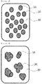
- FIG. 1 and FIG. 2 are mimetic diagrams presenting a form of particles including an inorganic material and a dispersion resin surrounding the inorganic material being dispersed into a solvent when preparing the slurry for forming a coating layer of a separator according to Example 1 and Comparative Example 1, respectively, of the present invention.
- the dispersion resin efficiently surrounds the inorganic material particles when preparing the slurry for forming a coating layer of a separator according to Example 1, and it can be seen that the particle sizes of the slurry particles may be reduced by preventing agglomeration of the inorganic material particles, and as a result, the sedimentation rate may be reduced.
- the coating layer thickness, loading, packing density, aeration time, adhesive strength and shrinkage rate were measured, and the results are shown in FIGs. 3a to 3e .
- FIG. 3a is a graph showing a thickness of the coating layer of the separator prepared in the examples and the comparative examples.
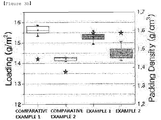
- FIG. 3b is a graph showing loading and packing density of the coating layer of the separator prepared in the examples and the comparative examples.
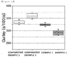
- FIG. 3c is a graph showing an aeration time (Gurley) of the coating layer of the separator prepared in the examples and the comparative examples.
- the aeration time measures a time taken for 100 cc of air to permeate a certain area, and from the aeration time, the degree of porosity of the coating layer may be identified. For example, in Comparative Examples 1 and 2, dispersibility of the slurry particles was not favorable when forming the coating layer of the separator causing agglomeration, which required longer time for air to permeate the coating layer, and the aeration time increased compared to the examples.
- FIG. 3d is a graph showing adhesive strength (Anode-Sepa Lami) of, when laminating the coating layer of the separator prepared in the examples and the comparative examples on a negative electrode, the coating layer with the negative electrode.
- FIG. 3e is a graph showing a shrinkage rate (MD*TD Shrinkage) of the separator prepared in the examples and the comparative examples.
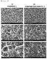
- FIG. 4 shows scanning electron microscope (SEM) images on the coating layer surface of the separator prepared in each of Example 1 and Comparative Example 1 ((a): Example 1, (b): Comparative Example 1).
- a separator was prepared using the same composition as in Example 1, while a first dispersion solution pre-dispersing inorganic material particles 1 (Al 2 O 3 ) into a solvent with a dispersion resin was prepared, a second dispersion solution pre-dispersing inorganic material particles 2 (AlOOH) into a solvent with a dispersion resin was prepared, these first dispersion solution and second dispersion solution were mixed, and a binder was added thereto to prepare slurry, and a separator using the same was prepared.
- a first dispersion solution pre-dispersing inorganic material particles 1 Al 2 O 3
- AlOOH second dispersion solution pre-dispersing inorganic material particles 2
- a separator was prepared using the same composition as in Example 1, while a first dispersion solution pre-dispersing inorganic material particles 1 (Al 2 O 3 ) into a solvent with a dispersion resin was prepared, and then a binder was added thereto to prepare first slurry.
- a second dispersion solution pre-dispersing inorganic material particles 2 (AlOOH) into a solvent with a dispersion resin was prepared, and then a binder was added thereto to prepare second slurry.
- Example 3 Based on the results described in Table 3, it was seen that, when forming a separator coating layer using two types of inorganic material particles, the slurry of Example 1 prepared by mixing two types of inorganic material particles, and pre-dispersing into a solvent with a dispersion resin had smaller particle sizes.
Landscapes
- Chemical & Material Sciences (AREA)
- Chemical Kinetics & Catalysis (AREA)
- Electrochemistry (AREA)
- General Chemical & Material Sciences (AREA)
- Engineering & Computer Science (AREA)
- Manufacturing & Machinery (AREA)
- Materials Engineering (AREA)
- Inorganic Chemistry (AREA)
- Composite Materials (AREA)
- Cell Separators (AREA)
Abstract
Description
- This application claims priority to and the benefits of Korean Patent Application No.
10-2017-0012463 10-2018-0004846 - The present invention relates to a method for preparing a separator usable in an electrochemical device, a separator prepared using the same, and an electrochemical device including the same.
- Interests in energy storage technologies have been increasingly growing recently. As applications have expanded to energy of mobile phones, camcorders and notebook PCs, and furthermore, to electric vehicles, efforts on the research and development of electrochemical devices have been more and more materialized.
- Electrochemical devices are fields receiving most attention in such aspects and among these, development of secondary batteries capable of charge and discharge have been the focus of attention, and developing such batteries has been progressed to research and development on the design of new electrodes and batteries for enhancing capacity density and specific energy.
- Among currently used secondary batteries, lithium secondary batteries developed in early 1990s have received attention with advantages of having high operating voltage and significantly higher energy density compared to conventional batteries such as Ni-MH, Ni-Cd and sulfuric acid-lead batteries using an aqueous solution liquid electrolyte.
- Electrochemical devices such as above have been produced in many companies, however, they are very different in their safety features.
- For such electrochemical devices, evaluating safety and securing safety are very important. A most important consideration is not to inflict an injury on a user in case of an electrochemical device malfunction, and for such a purpose, ignition and smoking generation and the like in an electrochemical device have been strictly regulated in the safety requirement. In the safety features of an electrochemical device, there is great concern for explosion when thermal runaway occurs due to electrochemical device overheating, or a separator is penetrated.
- Meanwhile, as a separator of an electrochemical device, a porous non-woven fabric substrate may be used for saving manufacturing costs. However, a separator using a porous non-woven fabric substrate has a problem of being fractured when manufacturing an electrochemical device due to a weakness of weak mechanical strength. In addition thereto, a leak current may be generated when operating an electrochemical device since pore sizes of the non-woven fabric substrate are large, which resultantly causes a problem of decreasing an insulating property of a separator.
- In order to form a coating layer of a stability reinforced separator (SRS) currently mass-produced, a method of mixing a binder and a dispersion resin and dissolving the mixture in a solvent, and adding an inorganic material thereto has been used when preparing slurry for forming a coating layer.
- However, in this case, the dispersion resin is not able to surround the inorganic material while being mixed with the binder, and more dispersion resin than is necessary is added, and excessive energy may be consumed in a process for dispersing the inorganic material.
- Accordingly, development of technologies capable of efficiently dispersing an inorganic material used when preparing slurry for forming a coating layer of a stability reinforced separator has been required.
- (Patent Document 1) Korean Patent Application Laid Open Publication No.
2009-0103010 - As a result of extensive studies in view of the above, the inventors of the present invention have identified that, by forming a coating layer on a separator usable in an electrochemical device, and specifically, by pre-dispersing a slurry inorganic material for forming a coating layer and a dispersion resin and then mixing a binder thereto to prepare slurry, the inorganic material may be efficiently surrounded with just a small amount of the dispersion resin enhancing dispersion efficiency, which resultantly improves phase stability by reducing particle sizes of the slurry for forming a coating layer, and as a result, energy consumed in a dispersion process may be reduced when preparing slurry for forming a separator coating layer.
- Accordingly, an aspect of the present invention provides a method for preparing a separator capable of enhancing process efficiency when preparing a separator used in an electrochemical device.
- Another aspect of the present invention provides a separator prepared using such a method for preparing a separator.
- Still another aspect of the present invention provides an electrochemical device including the separator.
- According to an aspect of the present invention, there is provided a method for preparing a separator including (S1) dispersing an inorganic material and a dispersion resin into a solvent to obtain a dispersion solution; (S2) mixing a binder with the dispersion solution to form a slurry; and (S3) coating the slurry on at least one surface of a substrate to form a coating layer.
- Herein, the dispersion resin may be a cyano resin including a -CN group, and may preferably be a cyano resin including a -CN group and an -OH group. The cyano resin may be one or more types selected from the group consisting of cyanoethyl pullulan, cyanoethyl polyvinyl alcohol, cyanoethyl cellulose and cyanoethyl sucrose.
- In addition, a content of the dispersion resin in the slurry may be from 1% by weight to 3% by weight.
- According to another aspect of the present invention, there is provided a separator prepared using the method for preparing a separator.
- According to still another aspect of the present invention, there is provided an electrochemical device including a positive electrode, a negative electrode, and a separator provided between the positive electrode and the negative electrode, and the electrochemical device may be a lithium ion battery.
- According to a method for preparing a separator of the present invention, by a process of pre-dispersing an inorganic material and a dispersion resin into a solvent and mixing a binder thereto afterward when preparing slurry for forming a coating layer of a separator, the dispersion resin efficiently surrounds the inorganic material. Accordingly, agglomeration of the inorganic material may be prevented, and particle sizes of the slurry become smaller and phase stability thereof becomes favorable.
- In addition, the inorganic material can be effectively dispersed in the solvent with just a small amount of the dispersion resin, and therefore, raw material costs and energy required in the process can be saved.
- The separator prepared as above has reinforced stability, and when used in an electrochemical device, thermal and electrochemical stability and performance of the electrochemical device can be enhanced.
-
-
FIG. 1 is a mimetic diagram presenting a form of particles including an inorganic material and a dispersion resin surrounding the inorganic material being dispersed into a solvent when preparing slurry for forming a coating layer of a separator according to Example 1 of the present invention. -
FIG. 2 is a mimetic diagram presenting a form of particles including an inorganic material and a dispersion resin surrounding the inorganic material being dispersed into a solvent when preparing slurry for forming a coating layer of a separator according to Comparative Example 1 of the present invention. -
FIG. 3a is a graph showing a thickness of a coating layer of a separator prepared in examples and comparative examples. -
FIG. 3b is a graph showing loading and packing density of a coating layer of a separator prepared in examples and comparative examples. -
FIG. 3c is a graph showing an aeration time (Gurley) of a coating layer of a separator prepared in examples and comparative examples. -
FIG. 3d is a graph showing adhesive strength (Anode-Sepa Lami) of, when laminating a coating layer of a separator prepared in examples and comparative examples on a negative electrode, the coating layer with the negative electrode. -
FIG. 3e is a graph showing a shrinkage rate (MD*TD Shrinkage) of a separator prepared in examples and comparative examples. -
FIG. 4 shows scanning electron microscope (SEM) images on a surface of a coating layer of a separator prepared in each of Example 1 and Comparative Example 1 ((a): Example 1, (b): Comparative Example 1). - Hereinafter, the present invention will be described in more detail in order to illuminate the present invention.
- Terms or words used in the present specification and the claims are not to be interpreted limitedly to common or dictionary meanings, and shall be interpreted as meanings and concepts corresponding to technological ideas of the present disclosure based on a principle in which the inventors may suitably define the concepts of terms in order to describe the invention in the best possible way.
- The present invention relates to a method for preparing a separator usable in an electrochemical device, and the method for preparing a separator may include (S1) dispersing an inorganic material and a dispersion resin into a solvent to obtain a dispersion solution; (S2) mixing a binder with the dispersion solution to form a slurry; and (S3) coating the slurry on at least one surface of a substrate to form a coating layer.
- Hereinafter, the method for preparing a separator according to the present invention will be described in detail step by step.
- In (S1), a dispersion solution may be obtained by dispersing an inorganic material and a dispersion resin into a solvent.
- When only the inorganic material and the dispersion resin are dispersed first into the solvent, the dispersion resin may effectively surround a surface of the inorganic material compared to when a binder is dispersed together. Accordingly, agglomeration of the inorganic material is prevented, reducing particle sizes of prepared slurry and enhancing phase stability thereof.
- In addition, the inorganic material can be efficiently dispersed into the solvent with just a small amount of the dispersion resin, and therefore, raw material costs and energy consumed in the dispersion process can be saved.
- The inorganic material may be inorganic material particles, and the inorganic material particles are not particularly limited as long as they are electrochemically stable. In other words, the inorganic material particles that may be used in the present invention are not particularly limited as long as an oxidation and/or reduction reaction does not occur in an operating voltage range (for example, 0 V to 5 V based on Li/Li+) of a battery used. Particularly, using inorganic material particles having a high dielectric constant as the inorganic material particles contributes to an increase in the dissociation of an electrolyte salt in a liquid electrolyte, for example, a lithium salt, and may enhance ion conductivity of the liquid electrolyte.
- With the above-described reasons, the inorganic material particles may include high dielectric constant inorganic material particles having a dielectric constant of 5 or greater, and preferably 10 or greater. The inorganic material particles having a dielectric constant of 5 or greater may be one or more types selected from the group consisting of SrTiO3, SnO2, CeO2, MgO, NiO, CaO, ZnO, ZrO2, SiO2, Y2O3, Al2O3, AlOOH, Al(OH)3, TiO2, SiC, BaTiO3, Pb(Zrx, Ti1-x) O3 (PZT, herein, 0<x<1), Pb1-xLaxZr1-yTiyO3 (PLZT, herein, 0<x<1, 0<y<1), (1-x)Pb(Mg1/3Nb2/3)O3-xPbTiO3 (PMN-PT, herein, 0<x<1) and HfO2, but are not limited thereto, and electrochemically stable inorganic material particles having a dielectric constant of 5 or greater may be widely used.
- In addition, inorganic material particles having a lithium ion transfer ability, that is, inorganic material particles containing a lithium element but having a function of transferring lithium ions instead of storing the lithium may be used. The inorganic material particles having a lithium ion transfer ability may include lithium phosphate (Li3PO4 , lithium titanium phosphate (LixTiy(PO4)3, 0<x<2, 0<y<3), lithium aluminum titanium phosphate (LixAlyTiz(PO4)3, 0<x<2, 0<y<1, 0<z<3), (LiAlTiP)xOy-based glass (0<x<4, 0<y<13) such as 14Li2O-9Al2O338TiO2-39P2O5, lithium lanthanum titanate (LixLayTiO3, 0<x<2, 0<y<3), lithium germanium thiophosphate (LixGeyPzSw, 0<x<4, 0<y<1, 0<z<1, 0<w<5) such as Li3.25Ge0.25P0.75S4, lithium nitride (LixNy, 0<x<4, 0<y<2) such as Li3N, SiS2-based glass (LixSiySz, 0<x<3, 0<y<2, 0<z<4) such as Li3PO4-Li2S-SiS2, P2S5-based glass (LixPySz, 0<x<3, 0<y<3, 0<z<7) such as LiI-Li2S-P2S5, or mixtures thereof.
- The particle diameters of the inorganic material particles are not particularly limited, but may be from 0.001 µm to 100 µm so that the inorganic material particles are efficiently dispersed inside the coating layer. For example, when the particle diameters of the inorganic material particles are less than 0.001 µm, phase stability of the slurry may decline due to particle agglomeration, and when the particle diameters are greater than 100 µm, it may be difficult to carry out a coating process.
- The inorganic material as described above may be used in 10% by weight to 20% by weight.
- In the present invention, the dispersion resin may be a cyano resin including a -CN group, and in addition, the dispersion resin may be a cyano resin including both a -CN group and an -OH group.
- The -CN group is hydrophobic exhibiting a friendly property with a substrate and a binder, and enables uniform dispersion of the inorganic material particles. In addition, the -OH group is hydrophilic exhibiting an inorganic material-friendly property leading to favorable coatability for the inorganic material surface, which is advantageous in reducing particle sizes of the slurry particles.
- The cyano resin may be one or more types selected from the group consisting of acrylonitrile, cyanoethyl pullulan, cyanoethyl polyvinyl alcohol, cyanoethyl cellulose and cyanoethyl sucrose.
- In addition, the dispersion resin has a molecular weight of 200,000 or greater, which is effective for enhancing adhesive strength between a separator and an electrode and decreasing a shrinkage rate.
- The dispersion resin content in the slurry may be from 0.1% by weight to 3% by weight. When the dispersion resin content is less than 0.1% by weight, the dispersion resin has a relatively smaller weight than the inorganic material, and is not able to sufficiently surround the inorganic material surface, which may lead to agglomeration of the inorganic material particles or a decrease in the dispersion efficiency, and when the content is greater than 3% by weight, the weight of the dispersion resin is excessive causing re-agglomeration of the remaining dispersion resin after dispersing the inorganic material, which may decline performance of an electrochemical device.
- As the solvent, solvents having a low boiling point may be used so that the solvent may be readily removed after preparing a separator. Specifically, the solvent may be selected from the group consisting of acetone, methanol, ethanol, tetrahydrofuran, methylene chloride, chloroform, dimethylformamide, N-methyl-2-pyrrolidone (NMP), cyclohexane and water.
- Such a solvent may be used in 69% by weight to 89% by weight considering uniform dispersion of the slurry particles.
- When forming a dispersion solution by dispersing the inorganic material and the dispersion resin as described above into the solvent, a milling process may be used for the dispersion to enhance dispersion efficiency, however, dispersion methods used for inorganic material dispersion may be widely used.
- Meanwhile, when using two or more types of inorganic materials, the two or more types of inorganic materials need to be mixed, and then pre-dispersed into the solvent with the dispersion resin to have an advantage in decreasing particle sizes of the slurry particles.
- Subsequently, in (S2), slurry may be formed by mixing a binder to the dispersion solution.
- The binder may be one or more types selected from the group consisting of polyvinylidene fluoride (PVDF), chlorotrifluoroethylene (CTFE), polyethylene glycol (PEG), polypropylene glycol (PPG), toluene diisocyanate (TDI), polymethyl methacrylate, polyacrylonitrile, polyvinyl pyrrolidone, polyvinyl acetate, polyethylene-co-vinyl acetate, polyethylene oxide, cellulose acetate, cellulose acetate butyrate, cellulose acetate propionate, pullulan, carboxylmethyl cellulose, an acrylonitrile-styrene-butadiene copolymer and polyimide.
- When forming the slurry, the binder may be mixed in an amount of 0.3% by weight to 8% by weight, and when the binder is mixed in less than 0.3% by weight, the inorganic material may be peeled off from a substrate after coating the slurry on the substrate, and when mixed in greater than 8% by weight, the binder may function as resistance in a battery.
- The slurry may be formed by the slurry particles being connected by the binder, and herein, the slurry particles mean particles prepared in (S1) including an inorganic material and a dispersion resin layer surrounding the inorganic material.
- Particle sizes of the slurry particles included in the slurry may be from 1 µm to 3 µm. When the particle sizes of the slurry particles are less than 1 µm, the number of fine particles increases making uniform dispersion difficult, and when the particle sizes are greater than 3 µm, the particle sizes increase reducing phase stability.
- Meanwhile, when mixing the binder to the dispersion solution, the slurry particles sink at a proper rate inside the binder, and the slurry particles enhance a degree of dispersion inside the binder enabling to prepare uniform slurry, and therefore, separator stability may be reinforced.
- Herein, the slurry particles may have a sedimentation rate of 1.5 µm/s or lower, and the sedimentation rate decreasing within the range of 1.5 µm/s or lower is advantageous in uniform dispersion of the slurry particles, and enhancing phase stability thereof resulted therefrom. Specifically, the sedimentation rate may be greater than 0 µm/s and less than or equal to 1.5 µm/s, preferably from 0.1 µm/s to 1 µm/s and more preferably from 0.2 µm/s to 0.5 µm/s.
- Subsequently, in (S3), the slurry may be coated on at least one surface of a substrate to form a coating layer.
- Herein, the coating method may be one or more types selected from the group consisting of spray, inkjet, laser printing, screen printing and dispensing methods, but is not limited thereto.
- The substrate may be a polyolefin-based substrate commonly used in the art, and specifically a substrate including one or more types selected from the group consisting of high density polyethylene, linear low density polyethylene, low density polyethylene, ultra-high molecular weight polyethylene, polypropylene and derivatives thereof.
- The substrate may have a thickness of 1 µm to 100 µm. When the substrate has a thickness of less than 1 µm, mechanical properties may be difficult to maintain, and when the thickness is greater than 100 µm, the substrate may function as a resistive layer.
- A coating layer may be formed by coating the slurry on at least one surface of the substrate, and then drying the result.
- The present invention also relates to a separator prepared using a method for preparing a separator such as described above.
- The separator includes a substrate, and a coating layer coated on at least one surface of the substrate, and the coating layer may include core-shell-type slurry particles including a core including an inorganic material, and a shell including a dispersion resin surrounding the core.
- The content and the specific types of materials forming the substrate and the coating layer are the same as described above.
- In the separator according to the present invention, particle sizes of the slurry particles included in the coating layer are small of approximately 1 µm to 3 µm, and therefore, a property of reinforcing stability of the separator may be obtained due to excellent phase stability. In addition, raw material costs and energy consumed in the process may be saved since the amount of dispersant used in preparing the separator is small.
- The present invention also relates to an electrochemical device including a separator such as described above, and the electrochemical device may include a positive electrode, a negative electrode, and a separator provided between the positive electrode and the negative electrode.
- The electrochemical device may be a lithium ion battery, and the lithium ion battery may have enhanced thermal and electrochemical stability and battery performance at the same time by using a separator with reinforced stability.
- Hereinafter, preferred examples will be provided in order to illuminate the present invention, however, the following examples are for illustrative purposes only, and it will be obvious to those skilled in the art that various changes and modifications may be made within the scope and technological ideas of the present invention, and such changes and modifications also belong to the scope of the attached claims.
- In the following examples and comparative examples, separators were prepared in the compositions and dispersion orders as described in the following Table 1.
[Table 1] Example 1 Example 2 Comparative Example 1 Comparative Example 2 Inorganic Material Particles 1Name Al2O3 Al2O3 Al2O3 Al2O3 Weight 11.9% by weight 12.0% by weight 11.9% by weight 12.0% by weight Particle Diameter 5 µm 5 µm 5 µm 5 µm Inorganic Material Particles 2Name AlOOH AlOOH AlOOH AlOOH Weight 2.1% by weight 2.1% by weight 2.1% by weight 2.1% by weight Particle Diameter 5 µm 5 µm 5 µm 5 µm Dispersion Resin Name Cyanoethyl Pullulan Cyanoethyl Pullulan Cyanoethyl Pullulan Cyanoethyl Pullulan Weight 0.4% by weight 0.3% by weight 0.4% by weight 0.3% by weight Binder Name PVDF PVDF PVDF PVDF Weight 3.6% by weight 3.6% by weight 3.6% by weight 3.6% by weight Solvent Name Acetone Acetone Acetone Acetone Weight 82% by weight 82% by weight 82% by weight 82% by weight Solvent Dispersion Pre-dispersion ○ Pre-dispersion ○ Pre-dispersion × Pre-dispersion × Pre-dispersing Inorganic Material and Dispersion Resin Pre-dispersing Inorganic Material and Dispersion Resin After Dispersing Dispersion Resin and Binder, Mixing Inorganic Material After Dispersing Dispersion Resin and Binder, Mixing Inorganic Material - To a solution dissolving a dispersion resin in a solvent, inorganic material particles were added for pre-dispersion. The result was mixed for 1 hour, milled for 2 hours to prepare a dispersion solution. Herein, by the composition described in Table 1, acetone was used in 82% by weight as the solvent, cyanoethyl pullulan was used in 0.4% by weight as the dispersion resin, and Al2O3 was used in 11.9% by weight and AlOOH in 2.1% by weight as the inorganic material particles.
- After dispersing all the inorganic materials in the dispersion solution, 3.6% by weight of poly-vinylidene fluoride (PVDF), a binder, was introduced to the dispersion solution, and the result was milled for 20 minutes to prepare slurry.
- The slurry was coated on one surface of a high density polyethylene substrate using a dip coating method, and the result was dried to form a coating layer, and then a separator was prepared.
- A separator was prepared in the same manner as in Example 1, except that the cyanoethyl pullulan that is the dispersion resin was used in 0.3% by weight.
- A separator was prepared in the same manner as in Example 1, except that the cyanoethyl pullulan that is the dispersion resin was used in 3.5% by weight.
- A separator was prepared in the same manner as in Example 1, except that the cyanoethyl pullulan that is the dispersion resin was used in 0.05% by weight.
- A separator was prepared using the same composition and under the same condition as in Example 1, but in a different process order. To a solvent, a dispersion resin and a binder were introduced, the result went through processes of temperature raising and lowering, and then mixed
inorganic material particles - A separator was prepared in the same manner as in Comparative Example 1, except that the cyanoethyl pullulan that is the dispersion resin was used in 0.3% by weight.
- A separator was prepared in the same manner as in Comparative Example 1, except that the cyanoethyl pullulan that is the dispersion resin was used in 3.5% by weight.
- A separator was prepared in the same manner as in Comparative Example 1, except that the cyanoethyl pullulan that is the dispersion resin was used in 0.05% by weight.
- Hereinafter, particle sizes and a sedimentation rate were measured for the slurry for forming a coating layer using methods as follows in the experimental example.
- In addition, for the coating layer formed on the separator using the slurry for forming a coating layer, the coating layer thickness, loading, packing density, aeration time, adhesive strength with an electrode and shrinkage rate were measured using methods as follows.
- Sizes of the slurry particle were measured using a particle size analyzer (PSA, Melbourne).
- A sedimentation rate of the slurry particles was measured using a dispersion stability analyzer (Lumisizer LS651).
- A thickness of the coating layer was measured using wVL-50S (Mitutoyo Corporation).
- The separator was cut into 5 cm x 5 cm, weights before/after the coating were measured, and this was employed as loading.
- Packing density was calculated according to the following
Equation 1. - Packing density=loading/coating layer thickness
- An aeration time was measured using an air permeability measuring device (Asahi Seiko Co., Ltd.).
- Adhesive strength was evaluated by hot pressing with 8.5 mPa at 90°C, and measuring 180 degree peel-off strength using UTM equipment (LLOYD Instruments, LF plus).
- The 5 cmx5cm separator sample was stored for 30 minutes in a 150°C oven, and the shrunk length was measured to calculate a shrinkage rate.
- Particle sizes and a sedimentation rate of the slurry prepared in the examples and the comparative examples were measured, and the results are described in Table 2.
[Table 2] Dispersion Resin Content (% by Weight) Dispersion Resin Pre-Dispersion Particle Size (D50, µm) Sedimentation Rate (µm/s) Example 1 0.4 Pre-dispersion ○ 2.27 0.56 Example 2 0.3 Pre-dispersion ○ 3.66 0.47 Example 3 3.5 Pre-dispersion ○ 5.63 2.03 Example 4 0.05 Pre-dispersion ○ 8.84 13.13 Comparative Example 1 0.4 Pre-dispersion × 3.35 1.16 Comparative Example 2 0.3 Pre-dispersion × 7.35 2.81 Comparative Example 3 3.5 Pre-dispersion × 9.12 15.21 Comparative Example 4 0.05 Pre-dispersion × 12.4 20.94 - Based on the results described in Table 2, it was seen that, when comparing Example 1 and Comparative Example 1 using the same dispersion resin content, the slurry of Example 1 prepared by pre-dispersing an inorganic material with a dispersion resin, and then mixing a binder thereto had reduced particle sizes and sedimentation rate compared to the slurry of Comparative Example 1.
- In addition, when comparing Example 2 and Comparative Example 2 using the same dispersion resin content, it was also seen that the slurry of Example 2 prepared by pre-dispersing an inorganic material with a dispersion resin, and then mixing a binder thereto had reduced particle sizes and sedimentation rate compared to the slurry of Comparative Example 2.
- It was also seen that Example 3 pre-dispersing an inorganic material together with a dispersion resin and having a high dispersion resin content, and Example 4 having a low dispersion resin content had an increased sedimentation rate and increased slurry particle sizes.
- It was also seen that Comparative Example 3 dispersing a dispersion resin and a binder, and then mixing an inorganic material thereto instead of pre-dispersing an inorganic material into a dispersion resin, and having a high dispersion resin content, and Comparative Example 4 having a low dispersion resin also had an increased sedimentation rate and increased slurry particle sizes.
-
FIG. 1 and FIG. 2 are mimetic diagrams presenting a form of particles including an inorganic material and a dispersion resin surrounding the inorganic material being dispersed into a solvent when preparing the slurry for forming a coating layer of a separator according to Example 1 and Comparative Example 1, respectively, of the present invention. - When referring to
FIG. 1 , the dispersion resin efficiently surrounds the inorganic material particles when preparing the slurry for forming a coating layer of a separator according to Example 1, and it can be seen that the particle sizes of the slurry particles may be reduced by preventing agglomeration of the inorganic material particles, and as a result, the sedimentation rate may be reduced. - When referring to
FIG. 2 , it was seen that agglomeration of the inorganic material particles occurs when preparing the slurry for forming a coating layer of a separator according to Comparative Example 1. - For each of the coating layers of the separators prepared in the examples and the comparative examples, the coating layer thickness, loading, packing density, aeration time, adhesive strength and shrinkage rate were measured, and the results are shown in
FIGs. 3a to 3e . -
FIG. 3a is a graph showing a thickness of the coating layer of the separator prepared in the examples and the comparative examples. - When referring to
FIG. 3a , it was seen that, when comparing each of Example 1 and Comparative Example 1, and Example 2 and Comparative Example 2 using the same dispersion resin content, the coating layers of the separators prepared in Examples 1 and 2 had smaller thicknesses than Comparative Examples 1 and 2. -
FIG. 3b is a graph showing loading and packing density of the coating layer of the separator prepared in the examples and the comparative examples. - When referring to
FIG. 3b , it was seen that, when comparing each of Example 1 and Comparative Example 1, and Example 2 and Comparative Example 2 using the same dispersion resin content, the coating layers of the separators prepared in Examples 1 and 2 had reduced loading and increased packing density compared to Comparative Examples 1 and 2. -
FIG. 3c is a graph showing an aeration time (Gurley) of the coating layer of the separator prepared in the examples and the comparative examples. - When referring to
FIG. 3c , it was seen that, when comparing each of Example 1 and Comparative Example 1, and Example 2 and Comparative Example 2 using the same dispersion resin content, the coating layers of the separators prepared in Examples 1 and 2 had a reduced aeration time compared to Comparative Examples 1 and 2. - The aeration time measures a time taken for 100 cc of air to permeate a certain area, and from the aeration time, the degree of porosity of the coating layer may be identified. For example, in Comparative Examples 1 and 2, dispersibility of the slurry particles was not favorable when forming the coating layer of the separator causing agglomeration, which required longer time for air to permeate the coating layer, and the aeration time increased compared to the examples.
-
FIG. 3d is a graph showing adhesive strength (Anode-Sepa Lami) of, when laminating the coating layer of the separator prepared in the examples and the comparative examples on a negative electrode, the coating layer with the negative electrode. - When referring to
FIG. 3d , it was seen that, when comparing each of Example 1 and Comparative Example 1, and Example 2 and Comparative Example 2 using the same dispersion resin content, the coating layers of the separators prepared in Examples 1 and 2 had a reduced deviation in the adhesive strength with the negative electrode compared to Comparative Examples 1 and 2. -
FIG. 3e is a graph showing a shrinkage rate (MD*TD Shrinkage) of the separator prepared in the examples and the comparative examples. - When referring to
FIG. 3e , it was seen that, when comparing each of Example 1 and Comparative Example 1, and Example 2 and Comparative Example 2 using the same dispersion resin content, the coating layers of the separators prepared in Examples 1 and 2 had a reduced shrinkage rate compared to Comparative Examples 1 and 2. From these results, it was identified that the coating layers of the separators prepared in Examples 1 and 2 had reinforced thermal stability. -
FIG. 4 shows scanning electron microscope (SEM) images on the coating layer surface of the separator prepared in each of Example 1 and Comparative Example 1 ((a): Example 1, (b): Comparative Example 1). - When referring to
FIG. 4(a) , it was seen that the inorganic material particles were uniformly dispersed in the separator coating layer prepared in Example 1. - Meanwhile, when referring to
FIG. 4(b) , it was seen that agglomeration of the inorganic material particles was observed in the separator coating layer prepared in Comparative Example 1, and sizes of the particles were larger compared to Example 1. - A separator was prepared using the same composition as in Example 1, while a first dispersion solution pre-dispersing inorganic material particles 1 (Al2O3) into a solvent with a dispersion resin was prepared, a second dispersion solution pre-dispersing inorganic material particles 2 (AlOOH) into a solvent with a dispersion resin was prepared, these first dispersion solution and second dispersion solution were mixed, and a binder was added thereto to prepare slurry, and a separator using the same was prepared.
- A separator was prepared using the same composition as in Example 1, while a first dispersion solution pre-dispersing inorganic material particles 1 (Al2O3) into a solvent with a dispersion resin was prepared, and then a binder was added thereto to prepare first slurry. In addition, a second dispersion solution pre-dispersing inorganic material particles 2 (AlOOH) into a solvent with a dispersion resin was prepared, and then a binder was added thereto to prepare second slurry.
- Mixed slurry prepared by mixing these first slurry and second slurry was used to prepare a separator.
- For each of the separators prepared in Example 1, Comparative Example 1, Comparative Example 5 and Comparative Example 6, particle sizes of the pre-dispersion solution and the slurry formed during a process for preparing the slurry for forming a coating layer of the separator were each measured, and the results are described in the following Table 3.
[Table 3] Process Order Particle Size (D50, µm) Dispersion Solution after Pre-dispersion Slurry Example 1 1) Mix inorganic material particles 1. 98 4.11 2) Pre-disperse dispersion resin and inorganic material particles 3) Add binder to prepare slurry Comparative Example 1 1) Mix inorganic material particles 1 and 2- 3.94 2) Mix inorganic material particles, dispersion resin and binder to prepare slurry Comparative Example 5 1) Prepare first dispersion solution of inorganic material particles 1 by pre-dispersion10.40 10.80 2) Prepare second dispersion solution of inorganic material particles 2 by pre-dispersion3) Mix first dispersion solution and second dispersion solution 4) Add binder to prepare slurry Comparative Example 6 1) Prepare first slurry of inorganic material particles 1 by pre-dispersion- 11.3 2) Prepare second slurry of inorganic material particles 2 by pre-dispersion3) Prepare mixed slurry of first slurry and second slurry - Based on the results described in Table 3, it was seen that, when forming a separator coating layer using two types of inorganic material particles, the slurry of Example 1 prepared by mixing two types of inorganic material particles, and pre-dispersing into a solvent with a dispersion resin had smaller particle sizes.
- Hereinbefore, the present invention has been described with limited examples and drawings, however, the present invention is not limited thereto, and various modifications and changes may be made by those skilled in the art within technological ideas of the present invention and the range of equivalents of the attached claims to describe below.
Claims (17)
- A method for preparing a separator comprising:(S1) dispersing an inorganic material and a dispersion resin into a solvent to obtain a dispersion solution;(S2) mixing a binder with the dispersion solution to form a slurry; and(S3) coating the slurry on at least one surface of a substrate to form a coating layer.
- The method for preparing a separator of Claim 1, wherein the dispersion resin is a cyano resin including a - CN group.
- The method for preparing a separator of Claim 2, wherein the cyano resin further includes an -OH group.
- The method for preparing a separator of Claim 2, wherein the cyano resin is one or more types selected from the group consisting of acrylonitrile, cyanoethyl pullulan, cyanoethyl polyvinyl alcohol, cyanoethyl cellulose and cyanoethyl sucrose.
- The method for preparing a separator of Claim 1, wherein a content of the dispersion resin in the slurry is from 0.1% by weight to 3% by weight, based upon the total weight of the slurry.
- The method for preparing a separator of Claim 1, wherein the inorganic material is selected from the group consisting of inorganic material particles having a dielectric constant of 5 or greater, inorganic material particles having a lithium ion transfer ability, and a mixture thereof.
- The method for preparing a separator of Claim 1, wherein the inorganic material is inorganic material particles having particle diameters of 0.001 µm to 100 µm.
- The method for preparing a separator of Claim 1, wherein the inorganic material is two or more types of inorganic materials, and the method further comprising mixing the two or more types of inorganic materials prior to the (S1).
- The method for preparing a separator of Claim 1, wherein the binder is one or more types selected from the group consisting of a polyvinylidene fluoride (PVDF)-based copolymer, polyethylene glycol (PEG), polypropylene glycol (PPG), toluene diisocyanate (TDI), polymethyl methacrylate, polyacrylonitrile, polyvinyl pyrrolidone, polyvinyl acetate, polyethylene-co-vinyl acetate, polyethylene oxide, cellulose acetate, cellulose acetate butyrate, cellulose acetate propionate, pullulan, carboxylmethyl cellulose, an acrylonitrile-styrene-butadiene copolymer and polyimide.
- The method for preparing a separator of Claim 1, wherein particle sizes of slurry particles included in the slurry are from 1 µm to 3 µm.
- The method for preparing a separator of Claim 10, wherein a sedimentation rate of the slurry particles is from 0.1 µm/s to 1.5 µm/s.
- The method for preparing a separator of Claim 1, wherein the coating method is one or more types selected from the group consisting of spray, inkjet, laser printing, screen printing and dispensing methods.
- The method for preparing a separator of Claim 1, wherein the coating layer has a thickness of 20 µm to 25 µm.
- A separator prepared using the method of any one of Claims 1 to 13.
- The separator of Claim 14 comprising:a substrate; anda coating layer coated on at least one surface of the substrate,wherein the coating layer includes core-shell-type slurry particles including a core including an inorganic material, and a shell including a dispersion resin surrounding the core.
- An electrochemical device comprising:a positive electrode;a negative electrode; anda separator provided between the positive electrode and the negative electrode,wherein the separator is prepared using the method of any one of Claims 1 to 13.
- The electrochemical device of Claim 16, which is a lithium ion battery.
Applications Claiming Priority (3)
| Application Number | Priority Date | Filing Date | Title |
|---|---|---|---|
| KR20170012463 | 2017-01-26 | ||
| KR1020180004846A KR102140130B1 (en) | 2017-01-26 | 2018-01-15 | Method for Preparing Separator, Separator Prepared by the Method and Electrochemical Device Including the Same |
| PCT/KR2018/000821 WO2018139805A1 (en) | 2017-01-26 | 2018-01-18 | Method for manufacturing separator, separator manufactured thereby, and electrochemical device comprising same |
Publications (3)
| Publication Number | Publication Date |
|---|---|
| EP3460873A1 true EP3460873A1 (en) | 2019-03-27 |
| EP3460873A4 EP3460873A4 (en) | 2019-08-21 |
| EP3460873B1 EP3460873B1 (en) | 2022-10-26 |
Family
ID=63250557
Family Applications (1)
| Application Number | Title | Priority Date | Filing Date |
|---|---|---|---|
| EP18744663.8A Active EP3460873B1 (en) | 2017-01-26 | 2018-01-18 | Method for manufacturing separator, separator manufactured thereby, and electrochemical device comprising same |
Country Status (3)
| Country | Link |
|---|---|
| EP (1) | EP3460873B1 (en) |
| KR (1) | KR102140130B1 (en) |
| CN (1) | CN109314205B (en) |
Cited By (1)
| Publication number | Priority date | Publication date | Assignee | Title |
|---|---|---|---|---|
| EP3579301A4 (en) * | 2017-11-24 | 2020-04-01 | LG Chem, Ltd. | METHOD FOR MANUFACTURING SEPARATOR, SEPARATOR THUS MANUFACTURED, AND ELECTROCHEMICAL ELEMENT COMPRISING SAID SEPARATOR |
Families Citing this family (3)
| Publication number | Priority date | Publication date | Assignee | Title |
|---|---|---|---|---|
| KR102421618B1 (en) | 2019-03-25 | 2022-07-14 | 주식회사 엘지에너지솔루션 | Manufacturing method of separator for electrochemical device |
| KR102787908B1 (en) * | 2019-11-18 | 2025-03-26 | 주식회사 엘지에너지솔루션 | A separator for an electrochemical device and an electrochemical device comprising the same |
| KR20230160508A (en) * | 2022-05-17 | 2023-11-24 | 주식회사 엘지에너지솔루션 | A preparing method of separator for lithium secondary battery, an separator for lithium secondary battery manufactured therefrom, and lithium secondary battery comprising the same |
Family Cites Families (9)
| Publication number | Priority date | Publication date | Assignee | Title |
|---|---|---|---|---|
| KR20090103010A (en) | 2008-03-27 | 2009-10-01 | 삼성에스디아이 주식회사 | Electrode Assembly and Lithium Ion Secondary battery having the Same |
| KR101173202B1 (en) * | 2010-02-25 | 2012-08-13 | 주식회사 엘지화학 | Preparation method of separator, separator formed therefrom, and preparation method of electrochemical device containing the same |
| JP2012086490A (en) * | 2010-10-21 | 2012-05-10 | Nitto Denko Corp | Sheet |
| US20130244080A1 (en) * | 2012-03-16 | 2013-09-19 | Samsung Sdi Co., Ltd. | Separator for lithium secondary battery |
| KR101298340B1 (en) * | 2013-02-12 | 2013-08-20 | 삼성토탈 주식회사 | A coated porous separator and a secondary battery using the same |
| CN103647035B (en) * | 2013-12-18 | 2016-08-17 | 深圳市慧通天下科技股份有限公司 | High porosity composite diaphragm and preparation method thereof, high-power battery |
| KR20160133276A (en) * | 2015-05-12 | 2016-11-22 | 주식회사 엘지화학 | A separator for a electrochemical device and a method for manufacturing the same |
| KR20170071204A (en) * | 2015-12-15 | 2017-06-23 | 주식회사 엘지화학 | Separator for Electrochemical Device Containing Active Layer Comprising Core-Shell Particles and Preparation Method thereof |
| EP3579301A4 (en) * | 2017-11-24 | 2020-04-01 | LG Chem, Ltd. | METHOD FOR MANUFACTURING SEPARATOR, SEPARATOR THUS MANUFACTURED, AND ELECTROCHEMICAL ELEMENT COMPRISING SAID SEPARATOR |
-
2018
- 2018-01-15 KR KR1020180004846A patent/KR102140130B1/en active Active
- 2018-01-18 CN CN201880002333.4A patent/CN109314205B/en active Active
- 2018-01-18 EP EP18744663.8A patent/EP3460873B1/en active Active
Cited By (2)
| Publication number | Priority date | Publication date | Assignee | Title |
|---|---|---|---|---|
| EP3579301A4 (en) * | 2017-11-24 | 2020-04-01 | LG Chem, Ltd. | METHOD FOR MANUFACTURING SEPARATOR, SEPARATOR THUS MANUFACTURED, AND ELECTROCHEMICAL ELEMENT COMPRISING SAID SEPARATOR |
| US11450921B2 (en) | 2017-11-24 | 2022-09-20 | Lg Energy Solution, Ltd. | Separator fabrication method, separator fabricated thereby, and electrochemical element comprising same separator |
Also Published As
| Publication number | Publication date |
|---|---|
| CN109314205A (en) | 2019-02-05 |
| EP3460873B1 (en) | 2022-10-26 |
| CN109314205B (en) | 2022-07-08 |
| KR102140130B1 (en) | 2020-07-31 |
| EP3460873A4 (en) | 2019-08-21 |
| KR20180088280A (en) | 2018-08-03 |
Similar Documents
| Publication | Publication Date | Title |
|---|---|---|
| JP6824558B2 (en) | Separation membrane for batteries to which a functional binder is applied and electrochemical elements to which this is applied | |
| CN101960659B (en) | Separator having porous coating layer and electrochemical device comprising the same | |
| KR101743694B1 (en) | Separator having porous coating layer and electrochemical device having the same | |
| EP3883010B1 (en) | Coated separator for secondary battery, and method for manufacturing same | |
| CN110521021B (en) | Method for manufacturing separator, separator manufactured thereby, and electrochemical device including the same | |
| EP3614459B1 (en) | Separator comprising binders having different glass transition temperatures, and manufacturing method therefor | |
| EP2541644A2 (en) | Manufacturing method for separator, separator made therefrom, and manufacturing method for electrochemical device containing same | |
| CN115088128A (en) | Separator for lithium secondary battery and method of manufacturing the same | |
| EP3460873B1 (en) | Method for manufacturing separator, separator manufactured thereby, and electrochemical device comprising same | |
| KR20120035858A (en) | A electrochemical device for progressing cycle characteristic | |
| KR102228625B1 (en) | Porous separator for electric device and preparation method thereof | |
| CN110521023A (en) | Separator and electrochemical device comprising the same | |
| KR101751443B1 (en) | Separator having porous coating layer and electrochemical device having the same | |
| KR102277570B1 (en) | Separator and preparation method thereof | |
| KR20170093606A (en) | Separator and method for manufacturing thereof | |
| KR20170007211A (en) | Separator and electrochemical device containing the same | |
| KR20190044530A (en) | Electrode assembly and electrochemical device containing the same | |
| JP7673180B2 (en) | Separator for electrochemical device and method for producing same | |
| US11283134B2 (en) | Method for manufacturing separator, separator manufactured thereby, and electrochemical device comprising same | |
| CN116368677B (en) | Separator and electrochemical device including the separator | |
| KR20190075659A (en) | Manufacturing method of separator, separator manufactured therefrom and electrichemical device containing the same | |
| KR102953999B1 (en) | A separator for electrochemical device and a manufacturing method thereof | |
| EP4478515A1 (en) | Preparation method for separator, separator prepared thereby and electrochemical device comprising same |
Legal Events
| Date | Code | Title | Description |
|---|---|---|---|
| STAA | Information on the status of an ep patent application or granted ep patent |
Free format text: STATUS: THE INTERNATIONAL PUBLICATION HAS BEEN MADE |
|
| PUAI | Public reference made under article 153(3) epc to a published international application that has entered the european phase |
Free format text: ORIGINAL CODE: 0009012 |
|
| STAA | Information on the status of an ep patent application or granted ep patent |
Free format text: STATUS: REQUEST FOR EXAMINATION WAS MADE |
|
| 17P | Request for examination filed |
Effective date: 20181218 |
|
| AK | Designated contracting states |
Kind code of ref document: A1 Designated state(s): AL AT BE BG CH CY CZ DE DK EE ES FI FR GB GR HR HU IE IS IT LI LT LU LV MC MK MT NL NO PL PT RO RS SE SI SK SM TR |
|
| AX | Request for extension of the european patent |
Extension state: BA ME |
|
| A4 | Supplementary search report drawn up and despatched |
Effective date: 20190718 |
|
| RIC1 | Information provided on ipc code assigned before grant |
Ipc: H01M 10/0525 20100101ALI20190712BHEP Ipc: H01M 2/16 20060101ALI20190712BHEP Ipc: H01M 2/14 20060101AFI20190712BHEP |
|
| DAV | Request for validation of the european patent (deleted) | ||
| DAX | Request for extension of the european patent (deleted) | ||
| STAA | Information on the status of an ep patent application or granted ep patent |
Free format text: STATUS: EXAMINATION IS IN PROGRESS |
|
| 17Q | First examination report despatched |
Effective date: 20211015 |
|
| RAP1 | Party data changed (applicant data changed or rights of an application transferred) |
Owner name: LG ENERGY SOLUTION LTD. |
|
| RAP3 | Party data changed (applicant data changed or rights of an application transferred) |
Owner name: LG ENERGY SOLUTION, LTD. |
|
| REG | Reference to a national code |
Ref country code: DE Ref legal event code: R079 Ref document number: 602018042258 Country of ref document: DE Free format text: PREVIOUS MAIN CLASS: H01M0002140000 Ipc: H01M0050403000 |
|
| GRAP | Despatch of communication of intention to grant a patent |
Free format text: ORIGINAL CODE: EPIDOSNIGR1 |
|
| STAA | Information on the status of an ep patent application or granted ep patent |
Free format text: STATUS: GRANT OF PATENT IS INTENDED |
|
| RIC1 | Information provided on ipc code assigned before grant |
Ipc: H01M 50/449 20210101ALI20220630BHEP Ipc: H01M 50/446 20210101ALI20220630BHEP Ipc: H01M 50/403 20210101AFI20220630BHEP |
|
| INTG | Intention to grant announced |
Effective date: 20220803 |
|
| GRAS | Grant fee paid |
Free format text: ORIGINAL CODE: EPIDOSNIGR3 |
|
| GRAA | (expected) grant |
Free format text: ORIGINAL CODE: 0009210 |
|
| STAA | Information on the status of an ep patent application or granted ep patent |
Free format text: STATUS: THE PATENT HAS BEEN GRANTED |
|
| AK | Designated contracting states |
Kind code of ref document: B1 Designated state(s): AL AT BE BG CH CY CZ DE DK EE ES FI FR GB GR HR HU IE IS IT LI LT LU LV MC MK MT NL NO PL PT RO RS SE SI SK SM TR |
|
| REG | Reference to a national code |
Ref country code: GB Ref legal event code: FG4D |
|
| REG | Reference to a national code |
Ref country code: CH Ref legal event code: EP |
|
| REG | Reference to a national code |
Ref country code: AT Ref legal event code: REF Ref document number: 1527720 Country of ref document: AT Kind code of ref document: T Effective date: 20221115 |
|
| REG | Reference to a national code |
Ref country code: DE Ref legal event code: R096 Ref document number: 602018042258 Country of ref document: DE |
|
| REG | Reference to a national code |
Ref country code: IE Ref legal event code: FG4D |
|
| REG | Reference to a national code |
Ref country code: SE Ref legal event code: TRGR |
|
| REG | Reference to a national code |
Ref country code: ES Ref legal event code: FG2A Ref document number: 2931534 Country of ref document: ES Kind code of ref document: T3 Effective date: 20221230 |
|
| REG | Reference to a national code |
Ref country code: LT Ref legal event code: MG9D |
|
| REG | Reference to a national code |
Ref country code: NL Ref legal event code: MP Effective date: 20221026 |
|
| REG | Reference to a national code |
Ref country code: AT Ref legal event code: MK05 Ref document number: 1527720 Country of ref document: AT Kind code of ref document: T Effective date: 20221026 |
|
| REG | Reference to a national code |
Ref country code: HU Ref legal event code: AG4A Ref document number: E060498 Country of ref document: HU |
|
| PG25 | Lapsed in a contracting state [announced via postgrant information from national office to epo] |
Ref country code: NL Free format text: LAPSE BECAUSE OF FAILURE TO SUBMIT A TRANSLATION OF THE DESCRIPTION OR TO PAY THE FEE WITHIN THE PRESCRIBED TIME-LIMIT Effective date: 20221026 |
|
| PG25 | Lapsed in a contracting state [announced via postgrant information from national office to epo] |
Ref country code: PT Free format text: LAPSE BECAUSE OF FAILURE TO SUBMIT A TRANSLATION OF THE DESCRIPTION OR TO PAY THE FEE WITHIN THE PRESCRIBED TIME-LIMIT Effective date: 20230227 Ref country code: NO Free format text: LAPSE BECAUSE OF FAILURE TO SUBMIT A TRANSLATION OF THE DESCRIPTION OR TO PAY THE FEE WITHIN THE PRESCRIBED TIME-LIMIT Effective date: 20230126 Ref country code: LT Free format text: LAPSE BECAUSE OF FAILURE TO SUBMIT A TRANSLATION OF THE DESCRIPTION OR TO PAY THE FEE WITHIN THE PRESCRIBED TIME-LIMIT Effective date: 20221026 Ref country code: FI Free format text: LAPSE BECAUSE OF FAILURE TO SUBMIT A TRANSLATION OF THE DESCRIPTION OR TO PAY THE FEE WITHIN THE PRESCRIBED TIME-LIMIT Effective date: 20221026 Ref country code: AT Free format text: LAPSE BECAUSE OF FAILURE TO SUBMIT A TRANSLATION OF THE DESCRIPTION OR TO PAY THE FEE WITHIN THE PRESCRIBED TIME-LIMIT Effective date: 20221026 |
|
| PG25 | Lapsed in a contracting state [announced via postgrant information from national office to epo] |
Ref country code: RS Free format text: LAPSE BECAUSE OF FAILURE TO SUBMIT A TRANSLATION OF THE DESCRIPTION OR TO PAY THE FEE WITHIN THE PRESCRIBED TIME-LIMIT Effective date: 20221026 Ref country code: LV Free format text: LAPSE BECAUSE OF FAILURE TO SUBMIT A TRANSLATION OF THE DESCRIPTION OR TO PAY THE FEE WITHIN THE PRESCRIBED TIME-LIMIT Effective date: 20221026 Ref country code: IS Free format text: LAPSE BECAUSE OF FAILURE TO SUBMIT A TRANSLATION OF THE DESCRIPTION OR TO PAY THE FEE WITHIN THE PRESCRIBED TIME-LIMIT Effective date: 20230226 Ref country code: HR Free format text: LAPSE BECAUSE OF FAILURE TO SUBMIT A TRANSLATION OF THE DESCRIPTION OR TO PAY THE FEE WITHIN THE PRESCRIBED TIME-LIMIT Effective date: 20221026 Ref country code: GR Free format text: LAPSE BECAUSE OF FAILURE TO SUBMIT A TRANSLATION OF THE DESCRIPTION OR TO PAY THE FEE WITHIN THE PRESCRIBED TIME-LIMIT Effective date: 20230127 |
|
| P01 | Opt-out of the competence of the unified patent court (upc) registered |
Effective date: 20230408 |
|
| REG | Reference to a national code |
Ref country code: DE Ref legal event code: R097 Ref document number: 602018042258 Country of ref document: DE |
|
| PG25 | Lapsed in a contracting state [announced via postgrant information from national office to epo] |
Ref country code: SM Free format text: LAPSE BECAUSE OF FAILURE TO SUBMIT A TRANSLATION OF THE DESCRIPTION OR TO PAY THE FEE WITHIN THE PRESCRIBED TIME-LIMIT Effective date: 20221026 Ref country code: RO Free format text: LAPSE BECAUSE OF FAILURE TO SUBMIT A TRANSLATION OF THE DESCRIPTION OR TO PAY THE FEE WITHIN THE PRESCRIBED TIME-LIMIT Effective date: 20221026 Ref country code: EE Free format text: LAPSE BECAUSE OF FAILURE TO SUBMIT A TRANSLATION OF THE DESCRIPTION OR TO PAY THE FEE WITHIN THE PRESCRIBED TIME-LIMIT Effective date: 20221026 Ref country code: DK Free format text: LAPSE BECAUSE OF FAILURE TO SUBMIT A TRANSLATION OF THE DESCRIPTION OR TO PAY THE FEE WITHIN THE PRESCRIBED TIME-LIMIT Effective date: 20221026 Ref country code: CZ Free format text: LAPSE BECAUSE OF FAILURE TO SUBMIT A TRANSLATION OF THE DESCRIPTION OR TO PAY THE FEE WITHIN THE PRESCRIBED TIME-LIMIT Effective date: 20221026 |
|
| PG25 | Lapsed in a contracting state [announced via postgrant information from national office to epo] |
Ref country code: SK Free format text: LAPSE BECAUSE OF FAILURE TO SUBMIT A TRANSLATION OF THE DESCRIPTION OR TO PAY THE FEE WITHIN THE PRESCRIBED TIME-LIMIT Effective date: 20221026 Ref country code: AL Free format text: LAPSE BECAUSE OF FAILURE TO SUBMIT A TRANSLATION OF THE DESCRIPTION OR TO PAY THE FEE WITHIN THE PRESCRIBED TIME-LIMIT Effective date: 20221026 |
|
| REG | Reference to a national code |
Ref country code: CH Ref legal event code: PL |
|
| PLBE | No opposition filed within time limit |
Free format text: ORIGINAL CODE: 0009261 |
|
| STAA | Information on the status of an ep patent application or granted ep patent |
Free format text: STATUS: NO OPPOSITION FILED WITHIN TIME LIMIT |
|
| PG25 | Lapsed in a contracting state [announced via postgrant information from national office to epo] |
Ref country code: LU Free format text: LAPSE BECAUSE OF NON-PAYMENT OF DUE FEES Effective date: 20230118 |
|
| REG | Reference to a national code |
Ref country code: BE Ref legal event code: MM Effective date: 20230131 |
|
| 26N | No opposition filed |
Effective date: 20230727 |
|
| PG25 | Lapsed in a contracting state [announced via postgrant information from national office to epo] |
Ref country code: LI Free format text: LAPSE BECAUSE OF NON-PAYMENT OF DUE FEES Effective date: 20230131 Ref country code: CH Free format text: LAPSE BECAUSE OF NON-PAYMENT OF DUE FEES Effective date: 20230131 |
|
| PG25 | Lapsed in a contracting state [announced via postgrant information from national office to epo] |
Ref country code: SI Free format text: LAPSE BECAUSE OF FAILURE TO SUBMIT A TRANSLATION OF THE DESCRIPTION OR TO PAY THE FEE WITHIN THE PRESCRIBED TIME-LIMIT Effective date: 20221026 Ref country code: BE Free format text: LAPSE BECAUSE OF NON-PAYMENT OF DUE FEES Effective date: 20230131 |
|
| PG25 | Lapsed in a contracting state [announced via postgrant information from national office to epo] |
Ref country code: IE Free format text: LAPSE BECAUSE OF NON-PAYMENT OF DUE FEES Effective date: 20230118 |
|
| PG25 | Lapsed in a contracting state [announced via postgrant information from national office to epo] |
Ref country code: IT Free format text: LAPSE BECAUSE OF FAILURE TO SUBMIT A TRANSLATION OF THE DESCRIPTION OR TO PAY THE FEE WITHIN THE PRESCRIBED TIME-LIMIT Effective date: 20221026 |
|
| PG25 | Lapsed in a contracting state [announced via postgrant information from national office to epo] |
Ref country code: MC Free format text: LAPSE BECAUSE OF FAILURE TO SUBMIT A TRANSLATION OF THE DESCRIPTION OR TO PAY THE FEE WITHIN THE PRESCRIBED TIME-LIMIT Effective date: 20221026 |
|
| PG25 | Lapsed in a contracting state [announced via postgrant information from national office to epo] |
Ref country code: MC Free format text: LAPSE BECAUSE OF FAILURE TO SUBMIT A TRANSLATION OF THE DESCRIPTION OR TO PAY THE FEE WITHIN THE PRESCRIBED TIME-LIMIT Effective date: 20221026 |
|
| PG25 | Lapsed in a contracting state [announced via postgrant information from national office to epo] |
Ref country code: BG Free format text: LAPSE BECAUSE OF FAILURE TO SUBMIT A TRANSLATION OF THE DESCRIPTION OR TO PAY THE FEE WITHIN THE PRESCRIBED TIME-LIMIT Effective date: 20221026 |
|
| PG25 | Lapsed in a contracting state [announced via postgrant information from national office to epo] |
Ref country code: BG Free format text: LAPSE BECAUSE OF FAILURE TO SUBMIT A TRANSLATION OF THE DESCRIPTION OR TO PAY THE FEE WITHIN THE PRESCRIBED TIME-LIMIT Effective date: 20221026 |
|
| PG25 | Lapsed in a contracting state [announced via postgrant information from national office to epo] |
Ref country code: CY Free format text: LAPSE BECAUSE OF FAILURE TO SUBMIT A TRANSLATION OF THE DESCRIPTION OR TO PAY THE FEE WITHIN THE PRESCRIBED TIME-LIMIT; INVALID AB INITIO Effective date: 20180118 |
|
| PG25 | Lapsed in a contracting state [announced via postgrant information from national office to epo] |
Ref country code: TR Free format text: LAPSE BECAUSE OF FAILURE TO SUBMIT A TRANSLATION OF THE DESCRIPTION OR TO PAY THE FEE WITHIN THE PRESCRIBED TIME-LIMIT Effective date: 20221026 |
|
| PGFP | Annual fee paid to national office [announced via postgrant information from national office to epo] |
Ref country code: GB Payment date: 20251222 Year of fee payment: 9 |
|
| PGFP | Annual fee paid to national office [announced via postgrant information from national office to epo] |
Ref country code: FR Payment date: 20251223 Year of fee payment: 9 |
|
| PGFP | Annual fee paid to national office [announced via postgrant information from national office to epo] |
Ref country code: SE Payment date: 20251223 Year of fee payment: 9 |
|
| PGFP | Annual fee paid to national office [announced via postgrant information from national office to epo] |
Ref country code: PL Payment date: 20251223 Year of fee payment: 9 |
|
| PGFP | Annual fee paid to national office [announced via postgrant information from national office to epo] |
Ref country code: HU Payment date: 20260129 Year of fee payment: 9 |
|
| PGFP | Annual fee paid to national office [announced via postgrant information from national office to epo] |
Ref country code: ES Payment date: 20260212 Year of fee payment: 9 |
|
| PGFP | Annual fee paid to national office [announced via postgrant information from national office to epo] |
Ref country code: DE Payment date: 20251222 Year of fee payment: 9 |