EP3460553A1 - Optical antenna device - Google Patents
Optical antenna device Download PDFInfo
- Publication number
- EP3460553A1 EP3460553A1 EP16904605.9A EP16904605A EP3460553A1 EP 3460553 A1 EP3460553 A1 EP 3460553A1 EP 16904605 A EP16904605 A EP 16904605A EP 3460553 A1 EP3460553 A1 EP 3460553A1
- Authority
- EP
- European Patent Office
- Prior art keywords
- optical
- shaft portion
- axis direction
- shaft portions
- lens system
- Prior art date
- Legal status (The legal status is an assumption and is not a legal conclusion. Google has not performed a legal analysis and makes no representation as to the accuracy of the status listed.)
- Granted
Links
Images

Classifications
-
- G—PHYSICS
- G01—MEASURING; TESTING
- G01S—RADIO DIRECTION-FINDING; RADIO NAVIGATION; DETERMINING DISTANCE OR VELOCITY BY USE OF RADIO WAVES; LOCATING OR PRESENCE-DETECTING BY USE OF THE REFLECTION OR RERADIATION OF RADIO WAVES; ANALOGOUS ARRANGEMENTS USING OTHER WAVES
- G01S7/00—Details of systems according to groups G01S13/00, G01S15/00, G01S17/00
- G01S7/48—Details of systems according to groups G01S13/00, G01S15/00, G01S17/00 of systems according to group G01S17/00
- G01S7/481—Constructional features, e.g. arrangements of optical elements
- G01S7/4811—Constructional features, e.g. arrangements of optical elements common to transmitter and receiver
- G01S7/4812—Constructional features, e.g. arrangements of optical elements common to transmitter and receiver transmitted and received beams following a coaxial path
-
- G—PHYSICS
- G01—MEASURING; TESTING
- G01S—RADIO DIRECTION-FINDING; RADIO NAVIGATION; DETERMINING DISTANCE OR VELOCITY BY USE OF RADIO WAVES; LOCATING OR PRESENCE-DETECTING BY USE OF THE REFLECTION OR RERADIATION OF RADIO WAVES; ANALOGOUS ARRANGEMENTS USING OTHER WAVES
- G01S7/00—Details of systems according to groups G01S13/00, G01S15/00, G01S17/00
- G01S7/48—Details of systems according to groups G01S13/00, G01S15/00, G01S17/00 of systems according to group G01S17/00
- G01S7/481—Constructional features, e.g. arrangements of optical elements
- G01S7/4818—Constructional features, e.g. arrangements of optical elements using optical fibres
-
- G—PHYSICS
- G02—OPTICS
- G02B—OPTICAL ELEMENTS, SYSTEMS OR APPARATUS
- G02B7/00—Mountings, adjusting means, or light-tight connections, for optical elements
- G02B7/02—Mountings, adjusting means, or light-tight connections, for optical elements for lenses
- G02B7/028—Mountings, adjusting means, or light-tight connections, for optical elements for lenses with means for compensating for changes in temperature or for controlling the temperature; thermal stabilisation
Definitions
- the present invention relates to an optical antenna device for transmitting and/or receiving a laser beam.
- Patent Literature 1 Japanese Patent Application Publication No. 1996-313774 discloses a technique of cancelling out the increase/decrease in the focal length of a plastic collimating lens and linear expansion of a lens barrel when a temperature change occurs.
- Patent Literature 1 Japanese Patent Application Publication No. 1996-313774 (for example, paragraph [0007]).
- Patent Literature 1 Even if athermal (temperature compensation) design as disclosed in Patent Literature 1 is made, it is found in some cases that the temperature dependence of optical characteristics of an optical lens system remains beyond an acceptable limit after manufacturing of the optical lens system. In such a case, it is necessary to perform redesign and re-trial production of a lens array and lens holding member, causing a problem where the trial production period and development cost are increased.
- an object of the present invention is to provide an optical antenna device which has a structure allowing for improvement in temperature dependence of an optical lens system by a simple and low-cost method.
- an optical antenna device which includes: an optical lens system configured to focus a laser beam incident thereon; an optical-system holding member configured to hold an outer peripheral edge of the optical lens system; an optical connection member placed on a rear focal plane of the optical lens system; a first shaft portion extending along an optical axis direction of the optical lens system from an end portion of the optical-system holding member toward the optical connection member, and having a first linear expansion coefficient in the optical axis direction; and a second shaft portion extending along the optical axis direction from a part of the optical connection member toward the optical-system holding member, and having a second linear expansion coefficient different from the first linear expansion coefficient in the optical axis direction.
- the first shaft portion and the second shaft portion are fixed to each other at a predetermined fixing position between the optical-system holding member and the optical connection member.
- the optical antenna device has a structure allowing for improvement in temperature dependence of optical characteristics of the optical lens system by a simple and low cost method.
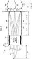
- FIG. 1 is a diagram schematically illustrating an overall configuration of an optical antenna device 1 of a first embodiment according to the present invention.
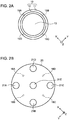
- FIG. 2A is a front view of the optical antenna device 1 of FIG. 1 as viewed from the Z-axis negative direction
- FIG. 2B is a rear view of the optical antenna device 1 of FIG. 1 as viewed from the Z-axis positive direction.
- FIG. 1 schematically illustrates an end surface representing a cross-sectional structure of a main part of the optical antenna device 1.
- the Z-axis illustrated in FIGS. 1 , 2A, and 2B is parallel to the optical axis direction of the optical antenna device 1.
- the X-axis and the Y-axis illustrated in FIGS. 1 , 2A, and 2B are orthogonal to each other, and orthogonal to the Z-axis.
- the optical antenna device 1 is incorporated for use in an active sensor using a laser beam, such as a Light Detection And Ranging (LIDAR) device.
- the LIDAR device is an active sensor capable of emitting a laser beam into the atmosphere, receiving scattered laser light reflected by a scattering body such as dust or fine particles floating in the atmosphere, and measuring a frequency shift or a wavelength shift due to the Doppler effect.
- the LIDAR device can measure the moving speed and moving direction of the scattering body as a wind speed and wind direction, respectively.
- the optical antenna device 1 includes: an optical lens system 13 with a cylindrical shape, configured to focus a laser beam on a focusing point P L in an external space or to receive a reflected laser beam RL; a focusing-distance adjuster 10 that is an optical-system holding member configured to hold an outer peripheral edge of the optical lens system 13; an optical input/output plate 20 that is a metal optical connection member placed on the rear focal plane of the optical lens system 13; optical input/output units 21A to 21E attached to the back surface of the optical input/output plate 20; and a shaft group including first shaft portions 15A to 15D and second shaft portions 16A to 16D disposed between the focusing-distance adjuster 10 and the optical input/output plate 20.
- the optical lens system 13 can include, for example, a lens array having a plurality of lenses arranged along the optical axis direction (Z-axis direction), and a lens barrel that holds an outer peripheral edge of the lens array. As illustrated in FIG. 2A , the optical lens system 13 has the circular front surface on which a laser beam is emitted or incident, and is placed inside an annular metal flange portion 11. In addition, an engagement portion 12 is formed between an outer circumferential surface of the optical lens system 13 and an inner circumferential surface of the flange portion 11.
- the focusing-distance adjuster 10 of the present embodiment includes the engagement portion 12 and the flange portion 11.
- the engagement portion 12 includes a male thread spirally formed on the inner circumferential surface of the flange portion 11, and a female thread spirally formed on the outer circumferential surface of the optical lens system 13. The male thread and the female thread are engaged with each other.
- a pair of a female thread spirally formed on the inner surface of the flange portion 11 and a female thread formed on the outer circumferential surface of the optical lens system 13 can be used.
- the engagement portion 12 can be formed in a manner that moves the optical lens system 13 rotating in the clockwise direction to the Z-axis positive direction with respect to the flange portion 11, and that moves the optical lens system 13 rotating in the counterclockwise direction to the Z-axis negative direction with respect to the flange portion 11. In this way, the user can finely adjust a focusing distance.
- the first shaft portions 15A to 15D are arranged at equal intervals along the circumferential direction of the flange portion 11, around the optical axis of the optical lens system 13, and one end portions (end portions on the Z-axis negative direction side) of the first shaft portions 15A to 15D are attached to the rear end portion of the flange portion 11.
- the first shaft portions 15A and 15C extend from the rear end portion of the flange portion 11 toward the optical input/output plate 20 (in the Z-axis positive direction).
- the first shaft portions 15B and 15D also extend from the rear end portion of the flange portion 11 toward the optical input/output plate 20 (in the Z-axis positive direction).
- the first shaft portions 15A to 15D are made from material with a linear expansion coefficient ⁇ in the optical axis direction, that is, in the Z-axis direction.
- the second shaft portions 16A to 16D are arranged at equal intervals along the circumferential direction of the circular optical input/output plate 20, and one end portions of the second shaft portions 16A to 16D are attached to the front surface (surface on the Z-axis negative direction side) of the optical input/output plate 20.
- the second shaft portions 16A and 16C extend from the front surface of the optical input/output plate 20 toward the flange portion 11 (in the Z-axis negative direction).
- the other second shaft portions 16B and 16D also extend from the front surface of the optical input/output plate 20 toward the flange portion 11.
- the second shaft portions 16A to 16D are made from material with a linear expansion coefficient ⁇ different from the linear expansion coefficient ⁇ in the optical axis direction, that is, in the Z-axis direction.
- a combination of the constituent material of the first shaft portions 15A to 15D and the constituent material of the second shaft portions 16A to 16D a combination of iron with a linear expansion coefficient of about 12 ⁇ 10 -6 /K and aluminum with a linear expansion coefficient of about 23 ⁇ 10 -6 /K, or a combination of stainless steel with a linear expansion coefficient of about 17 ⁇ 10 -6 /K and aluminum with a linear expansion coefficient of about 23 ⁇ 10 -6 /K can be used.
- the other end portions (end portions on the Z-axis positive direction side) of the first shaft portions 15A to 15D are connected to the other end portions (portions on the Z-axis negative direction side) of the second shaft portions 16A to 16D, respectively, in a direction along the optical axis direction.
- the end portion of the first shaft portion 15A and the end portion of the second shaft portion 16A are connected to each other, and the end portion of the first shaft portion 15C and the end portion of the second shaft portion 16C are connected to each other.
- first shaft portion 15B and the other end portion of the second shaft portion 16B are connected to each other, and the other end portion of the first shaft portion 15D and the other end portion of the second shaft portion 16D are connected to each other.
- a set of the first shaft portion 15A and the second shaft portion 16A, a set of the first shaft portion 15B and the second shaft portion 16B, a set of the first shaft portion 15C and the second shaft portion 16C, and a set of the first shaft portion 15D and the second shaft portion 16D have the same structure and the same size.
- a method of connecting the first shaft portions 15A to 15D and the second shaft portions 16A to 16D to each other is not particularly limited.
- a male thread can be formed on the other end portion of the first shaft portion 15A and a female thread adaptable to the male thread can be formed on the other end portion of the second shaft portion 15B.
- the first shaft portion 15A and the second shaft portion 15B can be connected to each other by engaging the male thread of the first shaft portion 15A with the female thread of the second shaft portion 15B.
- the optical input/output units 21A, 21B, ..., and 21E are provided on the back surface of the optical input/output plate 20. These optical input/output units 21A, 21B, ..., and 21E are optically connected to light propagation paths 22A, 22B, ..., and 22E, such as optical fibers. Five transmission laser beams respectively propagating through the light propagation paths 22A, 22B, ..., and 22E pass through the optical input/output units 21A to 21E and the holes of the optical input/output plate 20, and then are emitted toward the optical lens system 13. The optical lens system 13 focuses these five transmission laser beams at five points, respectively.
- the focusing point P L on the optical axis as illustrated in FIG. 1 is a point at which light emitted from the optical input/output unit 21E attached to the central portion of the optical input/output plate 20 is focused.
- the optical antenna device 1 has a configuration allowing for measurement in five lines of sight.
- a reflected laser beam from the external space is focused by the optical lens system 13, and then output to the light propagation paths 22A, 22B, ..., and 22E via the optical input/output units 21A to 21E.
- the optical lens system 13 focuses a laser beam input thereto from the optical input/output plate 20 at the point P L separated by a predetermined focusing distance L 2 .
- a flange back the length in the optical axis direction between the rear end portion of the optical lens system 13 and the front surface of the optical input/output plate 20, is denoted by L 1 .
- L 1 the length in the optical axis direction between the rear end portion of the optical lens system 13 and the front surface of the optical input/output plate 20
- L 1 the total length of the set of the first shaft portion 15A and the second shaft portion 16A in the optical axis direction coincides with the flange back L 1 .
- the user can change the flange back L 1 by rotating the optical lens system 13 to translationally move the optical lens system 13 in the optical axis direction.
- the focusing distance L 2 can be adjusted by changing the flange back L 1 .
- the focal length f of the optical lens system 13 shifts depending on a temperature change ⁇ T in the optical lens system 13.
- a shift ⁇ L 1 of the flange back L 1 (hereinafter also referred to as “flange back shift ⁇ L 1 ") depending on the temperature change ⁇ T is determined by the linear expansion coefficients ⁇ and ⁇ of the first shaft portions 15A to 15D and the second shaft portions 16A to 16D, and a ratio between the length in the optical axis direction of the first shaft portions 15A to 15D and the length in the optical axis direction of the second shaft portions 16A to 16D.
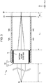
- a shift ⁇ f of the focal length f (hereinafter also referred to as "focal length shift ⁇ f") depending on the temperature change ⁇ T cancels out the shift in the focusing distance due to the flange back shift ⁇ L 1 .
- a ratio of the length in the optical axis direction of the first shaft portion 15A, to the flange back L 1 is denoted by c
- a ratio of the length in the optical axis direction of the second shaft portion 16A, to the flange back L 1 is denoted by 1 - c.
- the length in the optical axis direction of the first shaft portion 15A is L 1 ⁇ c
- the length in the optical axis direction of the second shaft portion 16A is L 1 ⁇ (1 - c).
- the effective linear expansion coefficient ⁇ can be adjusted only by changing the ratio c between the length of the first shaft portions 15A to 15D in the optical axis direction and the length of the second shaft portions 16A to 16D in the optical axis direction. Therefore, by only replacement of the first shaft portions 15A to 15D and the second shaft portions 16A to 16D, the shift in the focusing distance due to the temperature change can be suppressed.
- first shaft portions 15A to 15D and the second shaft portions 16A to 16D are formed as members different from the focusing-distance adjuster 10 that holds the optical lens system 13, the replacement of the first shaft portions 15A to 15D and the second shaft portions 16A to 16D is easily performed. Therefore, improvement in the temperature dependence of the optical characteristics of the optical lens system 13 can be achieved with a short time for trial production by a low cost and simple method. In addition, the flexibility of lens design can be improved. Further, in the present method, the dimensions of the first shaft portions 15A to 15D and the second shaft portions 16A to 16D after the replacement are not substantially changed, and also the outer shape of the optical antenna device 1 are not substantially changed. Therefore, it is possible to avoid the influence of the present method on an active sensor which includes the optical antenna device 1.
- ⁇ L 1 L 1 ⁇ ⁇ ⁇ ⁇ T .
- the following inequality expression (9) is preferably satisfied where the focal length shift ⁇ f and the length L 1 are measured in millimeters.
- the difference between the focal length shift ⁇ f and the flange back shift can be suppressed, so that an optical antenna configuration can be obtained in which focusing distance change due to the temperature change is suppressed.
- the optical antenna device 1 of the first embodiment even when it is found that the shift in the focusing distance L 2 due to the temperature change remains after manufacturing of the optical lens system 13, improvement in the temperature dependence of the optical characteristics of the optical lens system 13 can be achieved with a short time for trial production and without change of the outer shape of the optical antenna device 1, by a simple and low cost method of replacing the first shaft portions 15A to 15D and the second shaft portions 16A to 16D. Specifically, by adjusting the ratios c and 1 - c of the lengths of the first shaft portions 15A to 15D and second shaft portions 16A to 16D, the effective linear expansion coefficient ⁇ is adjusted to compensate for a shift in the focusing distance due to the temperature change.
- the flexibility in the design of the optical lens system 13 is improved. Because the first shaft portions 15A to 15D and the second shaft portions 16A to 16D are formed as members different from the focusing-distance adjuster 10 that holds the optical lens system 13, replacement of the first shaft portions 15A to 15D and the second shaft portions 16A to 16D is easily performed. Further, because only the adjustment of the ratios c and 1 - c is needed, the outside dimension of the optical antenna device 1 is not changed by the replacement. Therefore, there is an advantageous effect where the influence on the active sensor including the optical antenna device 1 is small.
- the optical input/output units 21A to 21E are attached at a total of five places, in order to measure about five lines of sight.
- the optical input/output unit may be attached at only one place depending on the application, or the optical input/output unit may be attached at six or more places.
- attachment positions of the optical input/output units are not limited to the positions illustrated in FIG. 2B .
- first shaft portions 15A to 15D and four second shaft portions 16A to 16D are used, although the number of shaft portions is not limited to four. More than four shaft portions may be adopted for improvement of rigidity, or Less than four shaft portions may be adopted for cost reduction.
- first shaft portions 15A to 15D and the second shaft portions 16A to 16D a set of cylindrical shaft portions having an optical path inside may be adopted for improvement of the rigidity.
- a helicoid may be used instead of the focusing-distance adjuster 10 having the engagement portion 12 described above.
- the optical lens system 13 itself can translate without rotating.
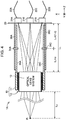
- FIG. 4 is a schematic configuration diagram of an optical antenna device 1A of the second embodiment according to the present invention.
- FIG. 5A is a front view of the optical antenna device 1A as viewed from the Z-axis negative direction
- FIG. 5B is a rear view of the optical antenna device 1A as viewed from the Z-axis positive direction.
- FIG. 4 schematically illustrates an end surface representing a cross-sectional structure of a main part of the optical antenna device 1A.
- the Z-axis illustrated in FIGS. 4 , 5A, and 5B is parallel to the optical axis direction of the optical antenna device 1A.
- the X-axis and the Y-axis illustrated in FIGS. 4 , 5A, and 5B are orthogonal to each other, and orthogonal to the Z-axis.
- the optical antenna device 1A includes the optical lens system 13, the focusing-distance adjuster 10, the optical input/output plate 20, fixing members 34A to 34D, first shaft portions 35A to 35D, and second shaft portions 36A to 36D.
- the configuration of the optical antenna device 1A of the present embodiment is the same as the configuration of the optical antenna device 1 of the first embodiment except that the fixing members 34A to 34D, the first shaft portions 35A to 35D, and the second shaft portions 36A to 36D are provided instead of the first shaft portions 15A to 15D and the second shaft portions 16A to 16D of FIG. 1 .
- the first shaft portions 35A to 35D are arranged at equal intervals along the circumferential direction of the flange portion 11 around the optical axis of the optical lens system 13, and one end portions (end portions on the Z-axis negative direction side) of the first shaft portions 35A to 35D are attached to the rear end portion of the flange portion 11.
- the first shaft portions 35A and 35C extend from the rear end portion of the flange portion 11 toward the optical input/output plate 20 (in the Z-axis positive direction).
- the other first shaft portions 35B and 35D also extend from the rear end portion of the flange portion 11 toward the optical input/output plate 20.
- the first shaft portions 35A to 35D are made from material with the linear expansion coefficient ⁇ in the optical axis direction, that is, in the Z-axis direction.
- the constituent material of the first shaft portions 35A to 35D is the same as the constituent material of the first shaft portions 15A to 15D of the first embodiment.
- the second shaft portions 36A to 36D are arranged at equal intervals along the circumferential direction of the circular optical input/output plate 20, and one end portions (end portions on the Z-axis positive direction side) of the second shaft portions 36A to 36D are attached to the front surface of the optical input/output plate 20.
- the second shaft portions 36A and 36C extend from the front surface of the optical input/output plate 20 toward the flange portion 11 (in the Z-axis negative direction).
- the other second shaft portions 36B and 36D also extend from the front surface of the optical input/output plate 20 toward the flange portion 11.
- the second shaft portions 36A to 36D are made from material with the linear expansion coefficient ⁇ different from the linear expansion coefficient ⁇ in the optical axis direction, that is, in the Z-axis direction.
- the constituent material of the second shaft portions 36A to 36D is the same as the constituent material of the second shaft portions 16A to 16D of the first embodiment.
- the first shaft portions 35A to 35D and the second shaft portions 36A to 36D extend with displacements therebetween in the radial direction perpendicular to the optical axis direction.
- first shaft portion 35A and the second shaft portion 36A are fixed to each other in the radial direction by the fixing member 34A and are overlapped with each other
- first shaft portion 35C and the second shaft portion 36C are fixed to each other in the radial direction by the fixing member 34C and are overlapped with each other.
- first shaft portion 35B and the second shaft portion 36B are fixed to each other in the radial direction by the fixing member 34B and are overlapped with each other
- first shaft portion 35D and the second shaft portion 36D are fixed to each other in the radial direction by the fixing member 34D and are overlapped with each other.
- a set of the first shaft portion 35A and the second shaft portion 36A, a set of the first shaft portion 35B and the second shaft portion 36B, a set of the first shaft portion 35C and the second shaft portion 36C, and a set of the first shaft portion 35D and the second shaft portion 36D have the same structure and the same size.
- a ratio of the length of the first shaft portion from the connection end portion of the first shaft portion 35A to the shaft fixing position, to the flange back L 1 is denoted by c
- a ratio of the length of the second shaft portion from the connection end portion of the second shaft portion 36A to the shaft fixing position, to the flange back L 1 is denoted by 1 - c.
- the effective linear expansion coefficient ⁇ then is represented by the following linear combination expression (2A), similar to the expression (2).
- ⁇ c ⁇ ⁇ + 1 ⁇ c ⁇ ⁇ .
- the expression (8) can be derived.
- the condition of the expression (9) is preferably satisfied.
- the effective linear expansion coefficient ⁇ can be changed only by changing the positions of the fixing members 34A to 34D in the optical axis direction, there is an advantage where it is not necessary to replace the first shaft portions 35A to 35D and the second shaft portions 36A to 36D.
- the length of the first shaft portions 35A to 35D and the length of the second shaft portions 36A to 36D are desirably set as long as possible.
- a movable range of the fixing members 34A to 34D can be widely set by setting the region long in which the first shaft portions 35A to 35D and the second shaft portions 36A to 36D are arranged to be overlapped with each other, whereby an adjustment range of the effective linear expansion coefficient ⁇ can be expanded.
- the length of the first shaft portions 35A to 35D and the length of the second shaft portions 36A to 36D are required to be shorter than the flange back L 1 .
- the reason is, for example, to prevent the end portions of the first shaft portions 35A to 35D from colliding with the optical input/output plate 20. It is also necessary that the end portions of the second shaft portions 36A to 36D do not collide with the flange portion 11.
- an optical antenna device in accordance with the present invention has a function to transmit and/or receive a laser beam
- the optical antenna device is suitable for use in active sensors using laser beams, such as LIDAR devices.
- 1, 1A Optical antenna devices; 10: Focusing-distance adjuster; 11: Flange portion; 12: Engagement portion; 13: optical lens system; 15A to 15D: First shaft portions; 16A to 16D: Second shaft portions; 20: Optical input/output plate; 21A to 21E: Optical input/output units; 22A to 22E: Light propagation paths; 34A to 34D: Fixing members; 35A to 35D: First shaft portions; 36A to 36D: Second shaft portions; and P L : Focusing point.
Landscapes
- Engineering & Computer Science (AREA)
- Physics & Mathematics (AREA)
- General Physics & Mathematics (AREA)
- Computer Networks & Wireless Communication (AREA)
- Radar, Positioning & Navigation (AREA)
- Remote Sensing (AREA)
- Optics & Photonics (AREA)
- Aerials With Secondary Devices (AREA)
- Lens Barrels (AREA)
- Optical Couplings Of Light Guides (AREA)
- Optical Radar Systems And Details Thereof (AREA)
Abstract
Description
- The present invention relates to an optical antenna device for transmitting and/or receiving a laser beam.
- In optical lens systems for use in transmission and reception of laser beams, when temperature changes occur, thermal expansion or contraction of lens arrays or lens holding members such as lens barrels possibly occurs, causing focal lengths or flange backs to change. This possibly causes focusing distances to focusing points of laser beams to change. When this phenomenon occurs, for example, a problem arises where measured values obtained by sensor devices using laser beams change depending on the temperature changes.
- In order to address such a problem, for example, Patent Literature 1 (Japanese Patent Application Publication No.
1996-313774 - Patent Literature 1: Japanese Patent Application Publication No.
1996-313774 - However, even if athermal (temperature compensation) design as disclosed in
Patent Literature 1 is made, it is found in some cases that the temperature dependence of optical characteristics of an optical lens system remains beyond an acceptable limit after manufacturing of the optical lens system. In such a case, it is necessary to perform redesign and re-trial production of a lens array and lens holding member, causing a problem where the trial production period and development cost are increased. - In addition, in a case where the outside dimension of an optical lens system is changed by redesign, when the redesigned optical lens system is incorporated in the sensor device, spatial interference between the redesigned optical lens system and other components possibly occurs. In this case, not only the redesign and re-trial production of the optical lens system but also a significant design change of the entire sensor device is required.
- In view of the foregoing, an object of the present invention is to provide an optical antenna device which has a structure allowing for improvement in temperature dependence of an optical lens system by a simple and low-cost method.
- In accordance with one aspect of the present invention, there is provided an optical antenna device which includes: an optical lens system configured to focus a laser beam incident thereon; an optical-system holding member configured to hold an outer peripheral edge of the optical lens system; an optical connection member placed on a rear focal plane of the optical lens system; a first shaft portion extending along an optical axis direction of the optical lens system from an end portion of the optical-system holding member toward the optical connection member, and having a first linear expansion coefficient in the optical axis direction; and a second shaft portion extending along the optical axis direction from a part of the optical connection member toward the optical-system holding member, and having a second linear expansion coefficient different from the first linear expansion coefficient in the optical axis direction. The first shaft portion and the second shaft portion are fixed to each other at a predetermined fixing position between the optical-system holding member and the optical connection member.
- In accordance with the present invention, the optical antenna device has a structure allowing for improvement in temperature dependence of optical characteristics of the optical lens system by a simple and low cost method.
-
-
FIG. 1 is a diagram schematically illustrating an example of an overall configuration of an optical antenna device of a first embodiment according to the present invention. -
FIG. 2A is a front view of the optical antenna device ofFIG. 1 , andFIG. 2B is a rear view of the optical antenna device ofFIG. 1 . -
FIG. 3 is a diagram schematically illustrating a temperature-dependent shift in a focal length of an optical lens system in the first embodiment. -
FIG. 4 is a diagram schematically illustrating an example of an overall configuration of an optical antenna device of a second embodiment according to the present invention. -
FIG. 5A is a front view of the optical antenna device ofFIG. 4 , andFIG. 2B is a rear view of the optical antenna device ofFIG. 4 . - Hereinafter, various embodiments according to the present invention will be described in detail with reference to the drawings. Note that, constituent elements denoted by the same reference sign throughout the drawings have the same configuration and the same function.
-
FIG. 1 is a diagram schematically illustrating an overall configuration of anoptical antenna device 1 of a first embodiment according to the present invention. In addition,FIG. 2A is a front view of theoptical antenna device 1 ofFIG. 1 as viewed from the Z-axis negative direction, andFIG. 2B is a rear view of theoptical antenna device 1 ofFIG. 1 as viewed from the Z-axis positive direction.FIG. 1 schematically illustrates an end surface representing a cross-sectional structure of a main part of theoptical antenna device 1. The Z-axis illustrated inFIGS. 1 ,2A, and 2B is parallel to the optical axis direction of theoptical antenna device 1. In addition, the X-axis and the Y-axis illustrated inFIGS. 1 ,2A, and 2B are orthogonal to each other, and orthogonal to the Z-axis. - The
optical antenna device 1 is incorporated for use in an active sensor using a laser beam, such as a Light Detection And Ranging (LIDAR) device. The LIDAR device is an active sensor capable of emitting a laser beam into the atmosphere, receiving scattered laser light reflected by a scattering body such as dust or fine particles floating in the atmosphere, and measuring a frequency shift or a wavelength shift due to the Doppler effect. On the basis of the measurement result, the LIDAR device can measure the moving speed and moving direction of the scattering body as a wind speed and wind direction, respectively. - As illustrated in
FIGS. 1 ,2A, and 2B , theoptical antenna device 1 includes: anoptical lens system 13 with a cylindrical shape, configured to focus a laser beam on a focusing point PL in an external space or to receive a reflected laser beam RL; a focusing-distance adjuster 10 that is an optical-system holding member configured to hold an outer peripheral edge of theoptical lens system 13; an optical input/output plate 20 that is a metal optical connection member placed on the rear focal plane of theoptical lens system 13; optical input/output units 21A to 21E attached to the back surface of the optical input/output plate 20; and a shaft group includingfirst shaft portions 15A to 15D andsecond shaft portions 16A to 16D disposed between the focusing-distance adjuster 10 and the optical input/output plate 20. - The
optical lens system 13 can include, for example, a lens array having a plurality of lenses arranged along the optical axis direction (Z-axis direction), and a lens barrel that holds an outer peripheral edge of the lens array. As illustrated inFIG. 2A , theoptical lens system 13 has the circular front surface on which a laser beam is emitted or incident, and is placed inside an annularmetal flange portion 11. In addition, anengagement portion 12 is formed between an outer circumferential surface of theoptical lens system 13 and an inner circumferential surface of theflange portion 11. - The focusing-
distance adjuster 10 of the present embodiment includes theengagement portion 12 and theflange portion 11. Theengagement portion 12 includes a male thread spirally formed on the inner circumferential surface of theflange portion 11, and a female thread spirally formed on the outer circumferential surface of theoptical lens system 13. The male thread and the female thread are engaged with each other. Instead of theengagement portion 12, a pair of a female thread spirally formed on the inner surface of theflange portion 11 and a female thread formed on the outer circumferential surface of theoptical lens system 13 can be used. When a user rotates theoptical lens system 13 around the optical axis relative to theflange portion 11, rotational motion of theoptical lens system 13 is converted into translational motion in the optical axis direction. For example, theengagement portion 12 can be formed in a manner that moves theoptical lens system 13 rotating in the clockwise direction to the Z-axis positive direction with respect to theflange portion 11, and that moves theoptical lens system 13 rotating in the counterclockwise direction to the Z-axis negative direction with respect to theflange portion 11. In this way, the user can finely adjust a focusing distance. - As illustrated in the front view of
FIG. 2A , thefirst shaft portions 15A to 15D are arranged at equal intervals along the circumferential direction of theflange portion 11, around the optical axis of theoptical lens system 13, and one end portions (end portions on the Z-axis negative direction side) of thefirst shaft portions 15A to 15D are attached to the rear end portion of theflange portion 11. In addition, as illustrated inFIG. 1 , thefirst shaft portions flange portion 11 toward the optical input/output plate 20 (in the Z-axis positive direction). Similarly, thefirst shaft portions 15B and 15D also extend from the rear end portion of theflange portion 11 toward the optical input/output plate 20 (in the Z-axis positive direction). Thefirst shaft portions 15A to 15D are made from material with a linear expansion coefficient α in the optical axis direction, that is, in the Z-axis direction. - On the other hand, as illustrated in the rear view of
FIG. 2B , thesecond shaft portions 16A to 16D are arranged at equal intervals along the circumferential direction of the circular optical input/output plate 20, and one end portions of thesecond shaft portions 16A to 16D are attached to the front surface (surface on the Z-axis negative direction side) of the optical input/output plate 20. In addition, as illustrated inFIG. 1 , thesecond shaft portions output plate 20 toward the flange portion 11 (in the Z-axis negative direction). Similarly, the othersecond shaft portions output plate 20 toward theflange portion 11. Thesecond shaft portions 16A to 16D are made from material with a linear expansion coefficient β different from the linear expansion coefficient α in the optical axis direction, that is, in the Z-axis direction. For example, as a combination of the constituent material of thefirst shaft portions 15A to 15D and the constituent material of thesecond shaft portions 16A to 16D, a combination of iron with a linear expansion coefficient of about 12 × 10-6/K and aluminum with a linear expansion coefficient of about 23 × 10-6/K, or a combination of stainless steel with a linear expansion coefficient of about 17 × 10-6/K and aluminum with a linear expansion coefficient of about 23 × 10-6/K can be used. - Further, at a predetermined position (shaft fixing position) between the rear end portion of the
flange portion 11 and the front surface of the optical input/output plate 20, the other end portions (end portions on the Z-axis positive direction side) of thefirst shaft portions 15A to 15D are connected to the other end portions (portions on the Z-axis negative direction side) of thesecond shaft portions 16A to 16D, respectively, in a direction along the optical axis direction. For example, as illustrated inFIG. 1 , the end portion of thefirst shaft portion 15A and the end portion of thesecond shaft portion 16A are connected to each other, and the end portion of thefirst shaft portion 15C and the end portion of thesecond shaft portion 16C are connected to each other. Similarly, the other end portion of the other first shaft portion 15B and the other end portion of thesecond shaft portion 16B are connected to each other, and the other end portion of thefirst shaft portion 15D and the other end portion of thesecond shaft portion 16D are connected to each other. A set of thefirst shaft portion 15A and thesecond shaft portion 16A, a set of the first shaft portion 15B and thesecond shaft portion 16B, a set of thefirst shaft portion 15C and thesecond shaft portion 16C, and a set of thefirst shaft portion 15D and thesecond shaft portion 16D have the same structure and the same size. In addition, a method of connecting thefirst shaft portions 15A to 15D and thesecond shaft portions 16A to 16D to each other is not particularly limited. For example, a male thread can be formed on the other end portion of thefirst shaft portion 15A and a female thread adaptable to the male thread can be formed on the other end portion of the second shaft portion 15B. Thefirst shaft portion 15A and the second shaft portion 15B can be connected to each other by engaging the male thread of thefirst shaft portion 15A with the female thread of the second shaft portion 15B. - On the other hand, as illustrated in
FIG. 2B , the optical input/output units output plate 20. These optical input/output units light propagation paths light propagation paths output units 21A to 21E and the holes of the optical input/output plate 20, and then are emitted toward theoptical lens system 13. Theoptical lens system 13 focuses these five transmission laser beams at five points, respectively. The focusing point PL on the optical axis as illustrated inFIG. 1 is a point at which light emitted from the optical input/output unit 21E attached to the central portion of the optical input/output plate 20 is focused. As described above, theoptical antenna device 1 has a configuration allowing for measurement in five lines of sight. Conversely, a reflected laser beam from the external space is focused by theoptical lens system 13, and then output to thelight propagation paths output units 21A to 21E. - As illustrated in
FIG. 1 , theoptical lens system 13 focuses a laser beam input thereto from the optical input/output plate 20 at the point PL separated by a predetermined focusing distance L2. In addition, a flange back, the length in the optical axis direction between the rear end portion of theoptical lens system 13 and the front surface of the optical input/output plate 20, is denoted by L1. In the present embodiment, it is assumed that the total length of the set of thefirst shaft portion 15A and thesecond shaft portion 16A in the optical axis direction coincides with the flange back L1. When a focal length of theoptical lens system 13 is denoted by f, the following relational expression (1) is satisfied.
- In this regard, the user can change the flange back L1 by rotating the
optical lens system 13 to translationally move theoptical lens system 13 in the optical axis direction. Based on the above expression (1), the focusing distance L2 can be adjusted by changing the flange back L1. - As illustrated in
FIG. 3 , the focal length f of theoptical lens system 13 shifts depending on a temperature change ΔT in theoptical lens system 13. On the other hand, it can be understood that a shift ΔL1 of the flange back L1 (hereinafter also referred to as "flange back shift ΔL1") depending on the temperature change ΔT is determined by the linear expansion coefficients α and β of thefirst shaft portions 15A to 15D and thesecond shaft portions 16A to 16D, and a ratio between the length in the optical axis direction of thefirst shaft portions 15A to 15D and the length in the optical axis direction of thesecond shaft portions 16A to 16D. In theoptical antenna device 1 of the present embodiment, a shift Δf of the focal length f (hereinafter also referred to as "focal length shift Δf") depending on the temperature change ΔT cancels out the shift in the focusing distance due to the flange back shift ΔL1. - Here, a ratio of the length in the optical axis direction of the
first shaft portion 15A, to the flange back L1, is denoted by c, and a ratio of the length in the optical axis direction of thesecond shaft portion 16A, to the flange back L1, is denoted by 1 - c. At this time, as illustrated inFIG. 1 , the length in the optical axis direction of thefirst shaft portion 15A is L1 × c, and the length in the optical axis direction of thesecond shaft portion 16A is L1 × (1 - c). In addition, when the linear expansion coefficient α of thefirst shaft portions 15A to 15D and the linear expansion coefficient β of thesecond shaft portions 16A to 16D are given, an effective linear expansion coefficient γ of the entire set of thefirst shaft portion 15A and thesecond shaft portion 16A is expressed by the following linear combination expression (2) .
- As described below, even when it is found that a shift in the focusing distance L2 due to a temperature change remains after manufacturing of the
optical lens system 13, the effective linear expansion coefficient γ can be adjusted only by changing the ratio c between the length of thefirst shaft portions 15A to 15D in the optical axis direction and the length of thesecond shaft portions 16A to 16D in the optical axis direction. Therefore, by only replacement of thefirst shaft portions 15A to 15D and thesecond shaft portions 16A to 16D, the shift in the focusing distance due to the temperature change can be suppressed. Because thefirst shaft portions 15A to 15D and thesecond shaft portions 16A to 16D are formed as members different from the focusing-distance adjuster 10 that holds theoptical lens system 13, the replacement of thefirst shaft portions 15A to 15D and thesecond shaft portions 16A to 16D is easily performed. Therefore, improvement in the temperature dependence of the optical characteristics of theoptical lens system 13 can be achieved with a short time for trial production by a low cost and simple method. In addition, the flexibility of lens design can be improved. Further, in the present method, the dimensions of thefirst shaft portions 15A to 15D and thesecond shaft portions 16A to 16D after the replacement are not substantially changed, and also the outer shape of theoptical antenna device 1 are not substantially changed. Therefore, it is possible to avoid the influence of the present method on an active sensor which includes theoptical antenna device 1. - Here, the flange back shift ΔL1 corresponding to the temperature change amount ΔT is expressed by an expression (3) below.

- Thermal expansion and change of a refractive index of the lens array occur due to the temperature change ΔT in the
optical lens system 13, whereby the focal length f shifts. In the present embodiment, with respect to the focal length shift Δf, by athermal design, the focal length f shifts to cause the focusing distance L2 to be constant, depending on the shift in the flange back L1 at the time of temperature change in the expression (1). When the effective linear expansion coefficient γ is used, the following expression (4) is approximately satisfied.
- Therefore, when we assume that the effective linear expansion coefficient is denoted by γp in a case where the focal length shift becomes equal to Δfp in response to the temperature change amount ΔT caused by variation in the optical characteristics due to factors such as manufacturing tolerance of the
optical lens system 13, the following expression (5) is approximately satisfied.
- In addition, when we assume that cp denotes the ratio of the length of first shaft portions to be substituted for the
first shaft portions 15A to 15D by the replacement of thefirst shaft portions 15A to 15D and thesecond shaft portions 16A to 16D, similarly to the expression (2), the following expression (6) is satisfied.
- When we assume that δc denotes a change amount of the ratio c generated by the replacement of the
first shaft portions 15A to 15D and thesecond shaft portions 16A to 16D, the following expression (7) is derived from the expressions (2) and (6).
- By substituting γp (= Δfp/(L1 × ΔT)) in the expression (5) into the expression (7) and rearranging the resulting expression, the change amount δc can be obtained. Therefore, by using the change amount δc, the following expression (8) is derived.

- Further, as an athermalization condition of the
optical lens system 13, the following inequality expression (9) is preferably satisfied where the focal length shift Δf and the length L1 are measured in millimeters.
- By satisfying the conditional expression (9), the difference between the focal length shift Δf and the flange back shift can be suppressed, so that an optical antenna configuration can be obtained in which focusing distance change due to the temperature change is suppressed.
- As described above, in the
optical antenna device 1 of the first embodiment, even when it is found that the shift in the focusing distance L2 due to the temperature change remains after manufacturing of theoptical lens system 13, improvement in the temperature dependence of the optical characteristics of theoptical lens system 13 can be achieved with a short time for trial production and without change of the outer shape of theoptical antenna device 1, by a simple and low cost method of replacing thefirst shaft portions 15A to 15D and thesecond shaft portions 16A to 16D. Specifically, by adjusting the ratios c and 1 - c of the lengths of thefirst shaft portions 15A to 15D andsecond shaft portions 16A to 16D, the effective linear expansion coefficient γ is adjusted to compensate for a shift in the focusing distance due to the temperature change. In addition, because only the adjustment of the effective linear expansion coefficient γ is required, the flexibility in the design of theoptical lens system 13 is improved. Because thefirst shaft portions 15A to 15D and thesecond shaft portions 16A to 16D are formed as members different from the focusing-distance adjuster 10 that holds theoptical lens system 13, replacement of thefirst shaft portions 15A to 15D and thesecond shaft portions 16A to 16D is easily performed. Further, because only the adjustment of the ratios c and 1 - c is needed, the outside dimension of theoptical antenna device 1 is not changed by the replacement. Therefore, there is an advantageous effect where the influence on the active sensor including theoptical antenna device 1 is small. - Note that, in the present embodiment, the optical input/
output units 21A to 21E are attached at a total of five places, in order to measure about five lines of sight. Instead, the optical input/output unit may be attached at only one place depending on the application, or the optical input/output unit may be attached at six or more places. In addition, attachment positions of the optical input/output units are not limited to the positions illustrated inFIG. 2B . - In addition, in the present embodiment, in order to physically connect the
flange portion 11 and the optical input/output plate 20 to each other, fourfirst shaft portions 15A to 15D and foursecond shaft portions 16A to 16D are used, although the number of shaft portions is not limited to four. More than four shaft portions may be adopted for improvement of rigidity, or Less than four shaft portions may be adopted for cost reduction. - Further, instead of the
first shaft portions 15A to 15D and thesecond shaft portions 16A to 16D, a set of cylindrical shaft portions having an optical path inside may be adopted for improvement of the rigidity. - In addition, a helicoid may be used instead of the focusing-
distance adjuster 10 having theengagement portion 12 described above. When the helicoid is used, theoptical lens system 13 itself can translate without rotating. - Next, a second embodiment will be described which is a modification of the first embodiment.
FIG. 4 is a schematic configuration diagram of anoptical antenna device 1A of the second embodiment according to the present invention. In addition,FIG. 5A is a front view of theoptical antenna device 1A as viewed from the Z-axis negative direction, andFIG. 5B is a rear view of theoptical antenna device 1A as viewed from the Z-axis positive direction.FIG. 4 schematically illustrates an end surface representing a cross-sectional structure of a main part of theoptical antenna device 1A. The Z-axis illustrated inFIGS. 4 ,5A, and 5B is parallel to the optical axis direction of theoptical antenna device 1A. In addition, the X-axis and the Y-axis illustrated inFIGS. 4 ,5A, and 5B are orthogonal to each other, and orthogonal to the Z-axis. - As illustrated in
FIGS. 4 ,5A, and 5B , theoptical antenna device 1A includes theoptical lens system 13, the focusing-distance adjuster 10, the optical input/output plate 20, fixingmembers 34A to 34D,first shaft portions 35A to 35D, andsecond shaft portions 36A to 36D. The configuration of theoptical antenna device 1A of the present embodiment is the same as the configuration of theoptical antenna device 1 of the first embodiment except that the fixingmembers 34A to 34D, thefirst shaft portions 35A to 35D, and thesecond shaft portions 36A to 36D are provided instead of thefirst shaft portions 15A to 15D and thesecond shaft portions 16A to 16D ofFIG. 1 . - In the present embodiment, as illustrated in the front view of
FIG. 5A , thefirst shaft portions 35A to 35D are arranged at equal intervals along the circumferential direction of theflange portion 11 around the optical axis of theoptical lens system 13, and one end portions (end portions on the Z-axis negative direction side) of thefirst shaft portions 35A to 35D are attached to the rear end portion of theflange portion 11. In addition, as illustrated inFIG. 4 , thefirst shaft portions flange portion 11 toward the optical input/output plate 20 (in the Z-axis positive direction). Similarly, the otherfirst shaft portions flange portion 11 toward the optical input/output plate 20. Thefirst shaft portions 35A to 35D are made from material with the linear expansion coefficient α in the optical axis direction, that is, in the Z-axis direction. The constituent material of thefirst shaft portions 35A to 35D is the same as the constituent material of thefirst shaft portions 15A to 15D of the first embodiment. - On the other hand, as illustrated in the rear view of
FIG. 5B , thesecond shaft portions 36A to 36D are arranged at equal intervals along the circumferential direction of the circular optical input/output plate 20, and one end portions (end portions on the Z-axis positive direction side) of thesecond shaft portions 36A to 36D are attached to the front surface of the optical input/output plate 20. In addition, as illustrated inFIG. 4 , thesecond shaft portions output plate 20 toward the flange portion 11 (in the Z-axis negative direction). Similarly, the othersecond shaft portions output plate 20 toward theflange portion 11. Thesecond shaft portions 36A to 36D are made from material with the linear expansion coefficient β different from the linear expansion coefficient α in the optical axis direction, that is, in the Z-axis direction. The constituent material of thesecond shaft portions 36A to 36D is the same as the constituent material of thesecond shaft portions 16A to 16D of the first embodiment. - The
first shaft portions 35A to 35D and thesecond shaft portions 36A to 36D extend with displacements therebetween in the radial direction perpendicular to the optical axis direction. In addition, as illustrated inFIG. 4 , at a predetermined position (shaft fixing position) between the rear end portion of theflange portion 11 and the front surface of the optical input/output plate 20, thefirst shaft portion 35A and thesecond shaft portion 36A are fixed to each other in the radial direction by the fixingmember 34A and are overlapped with each other, and thefirst shaft portion 35C and thesecond shaft portion 36C are fixed to each other in the radial direction by the fixingmember 34C and are overlapped with each other. Similarly, the otherfirst shaft portion 35B and thesecond shaft portion 36B are fixed to each other in the radial direction by the fixingmember 34B and are overlapped with each other, and thefirst shaft portion 35D and thesecond shaft portion 36D are fixed to each other in the radial direction by the fixingmember 34D and are overlapped with each other. A set of thefirst shaft portion 35A and thesecond shaft portion 36A, a set of thefirst shaft portion 35B and thesecond shaft portion 36B, a set of thefirst shaft portion 35C and thesecond shaft portion 36C, and a set of thefirst shaft portion 35D and thesecond shaft portion 36D have the same structure and the same size. - In the present embodiment, a ratio of the length of the first shaft portion from the connection end portion of the
first shaft portion 35A to the shaft fixing position, to the flange back L1, is denoted by c, and a ratio of the length of the second shaft portion from the connection end portion of thesecond shaft portion 36A to the shaft fixing position, to the flange back L1, is denoted by 1 - c. The effective linear expansion coefficient γ then is represented by the following linear combination expression (2A), similar to the expression (2).
- In addition, also in the present embodiment, the expression (8) can be derived. In addition, also in the present embodiment, the condition of the expression (9) is preferably satisfied.
- As described above, also in the second embodiment, effects can be obtained similar to those of the first embodiment. Specifically, even when it is found that the shift in the focusing distance L2 due to the temperature change remains after manufacturing of the
optical lens system 13, improvement in the temperature dependence of the optical characteristics of theoptical lens system 13 can be achieved with a short time for trial production without change of the outer shape of theoptical antenna device 1A, by a simple and low cost method of replacing the fixingmembers 34A to 34D, thefirst shaft portions 35A to 35D, and thesecond shaft portions 36A to 36D, or of changing positions of the fixingmembers 34A to 34D. In particular, in the present embodiment, because the effective linear expansion coefficient γ can be changed only by changing the positions of the fixingmembers 34A to 34D in the optical axis direction, there is an advantage where it is not necessary to replace thefirst shaft portions 35A to 35D and thesecond shaft portions 36A to 36D. - Note that, the length of the
first shaft portions 35A to 35D and the length of thesecond shaft portions 36A to 36D are desirably set as long as possible. The reason is that a movable range of the fixingmembers 34A to 34D can be widely set by setting the region long in which thefirst shaft portions 35A to 35D and thesecond shaft portions 36A to 36D are arranged to be overlapped with each other, whereby an adjustment range of the effective linear expansion coefficient γ can be expanded. - In this regard, the length of the
first shaft portions 35A to 35D and the length of thesecond shaft portions 36A to 36D are required to be shorter than the flange back L1. The reason is, for example, to prevent the end portions of thefirst shaft portions 35A to 35D from colliding with the optical input/output plate 20. It is also necessary that the end portions of thesecond shaft portions 36A to 36D do not collide with theflange portion 11. In addition, it is necessary to set a margin of the length of thefirst shaft portions 35A to 35D so that collision with the optical input/output plate 20 does not occur when thefirst shaft portions 35A to 35D thermally expand. It is also necessary to set a margin of the length of thesecond shaft portions 36A to 36D so that collision with theflange portion 11 does not occur when thesecond shaft portions 36A to 36D thermally expand. - Although the various embodiments according to the present invention have been described with reference to the drawings, these embodiments are examples of the present invention, and various forms other than these embodiments can be adopted.
- Note that, within the scope of the present invention, an arbitrary combination of the first and second embodiments, a modification of an arbitrary component of each embodiment, or omission of an arbitrary component in each embodiment is possible.
- Because an optical antenna device in accordance with the present invention has a function to transmit and/or receive a laser beam, the optical antenna device is suitable for use in active sensors using laser beams, such as LIDAR devices.
- 1, 1A: Optical antenna devices; 10: Focusing-distance adjuster; 11: Flange portion; 12: Engagement portion; 13: optical lens system; 15A to 15D: First shaft portions; 16A to 16D: Second shaft portions; 20: Optical input/output plate; 21A to 21E: Optical input/output units; 22A to 22E: Light propagation paths; 34A to 34D: Fixing members; 35A to 35D: First shaft portions; 36A to 36D: Second shaft portions; and PL: Focusing point.
Claims (5)
- An optical antenna device comprising:an optical lens system configured to focus a laser beam incident thereon;an optical-system holding member configured to hold an outer peripheral edge of the optical lens system;an optical connection member placed on a rear focal plane of the optical lens system;a first shaft portion extending along an optical axis direction of the optical lens system from an end portion of the optical-system holding member toward the optical connection member, and having a first linear expansion coefficient in the optical axis direction; anda second shaft portion extending along the optical axis direction from a part of the optical connection member toward the optical-system holding member, and having a second linear expansion coefficient different from the first linear expansion coefficient in the optical axis direction, whereinthe first shaft portion and the second shaft portion are fixed to each other at a predetermined fixing position between the optical-system holding member and the optical connection member.
- The optical antenna device according to claim 1, wherein an effective linear expansion coefficient of the first and second shaft portions as a whole is expressed by a linear combination expression given by

- The optical antenna device according to claim 1, wherein:a first end portion of the first shaft portion in the optical axis direction is connected to the end portion of the optical-system holding member,a first end portion of the second shaft portion in the optical axis direction is connected to the part of the optical connection member, anda second end portion of the first shaft portion in the optical axis direction and a second end portion of the second shaft portion in the optical axis direction are connected to each other at the fixing position.
- The optical antenna device according to claim 1, further comprising a fixing member to fix the first shaft portion and the second shaft portion to each other at the fixing position, wherein
a first end portion of the first shaft portion in the optical axis direction is connected to the end portion of the optical-system holding member,
a first end portion of the second shaft portion in the optical axis direction is connected to the part of the optical connection member, and
the first shaft portion and the second shaft portion extend along the optical axis direction with a displacement therebetween in a vertical direction to the optical axis direction, and are overlapped with each other in the vertical direction at the fixing position. - The optical antenna device according to claim 2, wherein a condition expression is satisfied which is given by

Applications Claiming Priority (1)
| Application Number | Priority Date | Filing Date | Title |
|---|---|---|---|
| PCT/JP2016/067053 WO2017212570A1 (en) | 2016-06-08 | 2016-06-08 | Optical antenna device |
Publications (3)
| Publication Number | Publication Date |
|---|---|
| EP3460553A1 true EP3460553A1 (en) | 2019-03-27 |
| EP3460553A4 EP3460553A4 (en) | 2019-06-26 |
| EP3460553B1 EP3460553B1 (en) | 2024-02-07 |
Family
ID=59969375
Family Applications (1)
| Application Number | Title | Priority Date | Filing Date |
|---|---|---|---|
| EP16904605.9A Active EP3460553B1 (en) | 2016-06-08 | 2016-06-08 | Optical antenna device |
Country Status (5)
| Country | Link |
|---|---|
| EP (1) | EP3460553B1 (en) |
| JP (1) | JP6203434B1 (en) |
| CN (1) | CN109313320A (en) |
| DK (1) | DK3460553T3 (en) |
| WO (1) | WO2017212570A1 (en) |
Cited By (1)
| Publication number | Priority date | Publication date | Assignee | Title |
|---|---|---|---|---|
| WO2020225399A1 (en) * | 2019-05-08 | 2020-11-12 | Zf Friedrichshafen Ag | Lidar system and housing for a lidar system |
Families Citing this family (3)
| Publication number | Priority date | Publication date | Assignee | Title |
|---|---|---|---|---|
| JP2020201331A (en) * | 2019-06-07 | 2020-12-17 | オムロン株式会社 | Optical assembly for three-dimensional measuring apparatus and three-dimensional measuring apparatus including the same |
| CN112099175B (en) * | 2020-08-31 | 2022-07-29 | 西安空间无线电技术研究所 | A defocus bow bimetal thermal compensation device for optical antenna |
| CN115846858A (en) * | 2022-12-05 | 2023-03-28 | 苏州钋镭自动化科技有限公司 | Real-time temperature compensation method for focus of laser cutting head |
Family Cites Families (18)
| Publication number | Priority date | Publication date | Assignee | Title |
|---|---|---|---|---|
| JPS62163474A (en) * | 1986-01-13 | 1987-07-20 | Hitachi Ltd | Fitting mechanism for solid-state image pickup element |
| JPH0253009U (en) * | 1988-10-06 | 1990-04-17 | ||
| US6040950A (en) * | 1998-01-05 | 2000-03-21 | Intel Corporation | Athermalized mounts for lenses |
| JP2001272587A (en) * | 2000-03-24 | 2001-10-05 | Konica Corp | Photographing lens unit |
| JP4413417B2 (en) * | 2000-12-18 | 2010-02-10 | 古河電気工業株式会社 | Laser diode module |
| JP2003185904A (en) * | 2001-12-21 | 2003-07-03 | Konica Corp | Camera |
| DE10220671B4 (en) * | 2002-05-10 | 2004-08-26 | Hella Kg Hueck & Co. | Optical system for a camera |
| JP3718199B2 (en) * | 2003-02-28 | 2005-11-16 | 松下電器産業株式会社 | Lens barrel |
| CN1723408A (en) * | 2003-07-08 | 2006-01-18 | 松下电器产业株式会社 | Beam shaping optical device, optical head, and optical information medium drive device |
| JP2005274997A (en) * | 2004-03-25 | 2005-10-06 | Nikon Corp | Optical system and optical apparatus |
| JP2007094293A (en) * | 2005-09-30 | 2007-04-12 | Ricoh Printing Systems Ltd | Semiconductor laser module |
| JPWO2007063932A1 (en) * | 2005-12-01 | 2009-05-07 | パナソニック株式会社 | Lens barrel |
| JP5452502B2 (en) * | 2007-12-27 | 2014-03-26 | エリクソン テレコムニカソンイス ソシエダット アノニマ | Optical space transmission communication equipment |
| CN201383027Y (en) * | 2009-03-30 | 2010-01-13 | 北京蓝思泰克科技有限公司 | Far infrared athermalizing optical system |
| FR2963439B1 (en) * | 2010-07-30 | 2012-09-14 | Sagem Defense Securite | PASSIVE MECHANICAL ATHERENT DEVICE, OPTICAL SYSTEM THEREFOR |
| JP2014174041A (en) * | 2013-03-11 | 2014-09-22 | Mitsubishi Electric Corp | Optical antenna and optical wave rader system |
| CN105103026B (en) * | 2013-04-09 | 2017-05-31 | 富士胶片株式会社 | camera device |
| US9625671B2 (en) * | 2013-10-23 | 2017-04-18 | Lasermax, Inc. | Laser module and system |
-
2016
- 2016-06-08 DK DK16904605.9T patent/DK3460553T3/en active
- 2016-06-08 JP JP2016572339A patent/JP6203434B1/en active Active
- 2016-06-08 EP EP16904605.9A patent/EP3460553B1/en active Active
- 2016-06-08 CN CN201680086280.XA patent/CN109313320A/en active Pending
- 2016-06-08 WO PCT/JP2016/067053 patent/WO2017212570A1/en not_active Ceased
Cited By (1)
| Publication number | Priority date | Publication date | Assignee | Title |
|---|---|---|---|---|
| WO2020225399A1 (en) * | 2019-05-08 | 2020-11-12 | Zf Friedrichshafen Ag | Lidar system and housing for a lidar system |
Also Published As
| Publication number | Publication date |
|---|---|
| JP6203434B1 (en) | 2017-09-27 |
| WO2017212570A1 (en) | 2017-12-14 |
| EP3460553A4 (en) | 2019-06-26 |
| CN109313320A (en) | 2019-02-05 |
| DK3460553T3 (en) | 2024-03-04 |
| JPWO2017212570A1 (en) | 2018-06-21 |
| EP3460553B1 (en) | 2024-02-07 |
Similar Documents
| Publication | Publication Date | Title |
|---|---|---|
| US11619718B2 (en) | Integrated optical structures for LiDAR and other applications employing multiple detectors | |
| EP3460553B1 (en) | Optical antenna device | |
| EP1729097B1 (en) | Photoelectric encoder | |
| US20150241636A1 (en) | Optical module and light transmission method | |
| US10520696B2 (en) | In-vehicle camera lens unit | |
| US20140169392A1 (en) | Laser emitter module and laser detecting system to which the laser emitter module is applied | |
| US20110242634A1 (en) | Scanning optical apparatus | |
| EP3021153B1 (en) | Optical apparatus, processing apparatus, and article manufacturing method | |
| US9575431B2 (en) | Optical scanning apparatus and image forming apparatus including the same | |
| US12546973B2 (en) | Optical system, image pickup apparatus, in-vehicle system, and moving apparatus | |
| US11802941B2 (en) | Sensor apparatus for detecting an object | |
| EP2538173A1 (en) | Method for arranging photoreceiving lens, and optical displacement sensor | |
| US20250076549A1 (en) | Optical communication optical system and optical communication apparatus | |
| JP6388753B2 (en) | Lens barrel | |
| JP7844219B2 (en) | Lens holding mechanism, optical device, control system, and moving device | |
| EP1870754A1 (en) | Lens optical system and photoelectric encoder | |
| US20260104580A1 (en) | Divergence variation compensating telescope | |
| JP6481435B2 (en) | Optical device | |
| US20260104573A1 (en) | Infrared lens, infrared optical system, and infrared imaging apparatus | |
| JP7764218B2 (en) | Optical system, distance measuring device and imaging system including the same | |
| CN113447939B (en) | Distance measuring device | |
| JP5938383B2 (en) | Phase modulation element, light source unit, and image forming apparatus using the same | |
| JP2012078155A (en) | Light-receiving lens, and optical displacement sensor | |
| JP2012181018A (en) | Movement information measuring device | |
| KR101771796B1 (en) | Lens |
Legal Events
| Date | Code | Title | Description |
|---|---|---|---|
| STAA | Information on the status of an ep patent application or granted ep patent |
Free format text: STATUS: THE INTERNATIONAL PUBLICATION HAS BEEN MADE |
|
| PUAI | Public reference made under article 153(3) epc to a published international application that has entered the european phase |
Free format text: ORIGINAL CODE: 0009012 |
|
| STAA | Information on the status of an ep patent application or granted ep patent |
Free format text: STATUS: REQUEST FOR EXAMINATION WAS MADE |
|
| 17P | Request for examination filed |
Effective date: 20181122 |
|
| AK | Designated contracting states |
Kind code of ref document: A1 Designated state(s): AL AT BE BG CH CY CZ DE DK EE ES FI FR GB GR HR HU IE IS IT LI LT LU LV MC MK MT NL NO PL PT RO RS SE SI SK SM TR |
|
| AX | Request for extension of the european patent |
Extension state: BA ME |
|
| A4 | Supplementary search report drawn up and despatched |
Effective date: 20190524 |
|
| RIC1 | Information provided on ipc code assigned before grant |
Ipc: G02B 7/04 20060101ALI20190520BHEP Ipc: G02B 7/02 20060101AFI20190520BHEP Ipc: G02B 6/32 20060101ALI20190520BHEP Ipc: G02B 6/42 20060101ALI20190520BHEP |
|
| DAV | Request for validation of the european patent (deleted) | ||
| DAX | Request for extension of the european patent (deleted) | ||
| STAA | Information on the status of an ep patent application or granted ep patent |
Free format text: STATUS: EXAMINATION IS IN PROGRESS |
|
| 17Q | First examination report despatched |
Effective date: 20220128 |
|
| REG | Reference to a national code |
Ref country code: DE Ref legal event code: R079 Free format text: PREVIOUS MAIN CLASS: G02B0007020000 Ref country code: DE Ref legal event code: R079 Ref document number: 602016085718 Country of ref document: DE Free format text: PREVIOUS MAIN CLASS: G02B0007020000 Ipc: G01S0007481000 |
|
| GRAP | Despatch of communication of intention to grant a patent |
Free format text: ORIGINAL CODE: EPIDOSNIGR1 |
|
| STAA | Information on the status of an ep patent application or granted ep patent |
Free format text: STATUS: GRANT OF PATENT IS INTENDED |
|
| RIC1 | Information provided on ipc code assigned before grant |
Ipc: G02B 7/02 20060101ALI20231006BHEP Ipc: G01S 7/481 20060101AFI20231006BHEP |
|
| INTG | Intention to grant announced |
Effective date: 20231102 |
|
| GRAS | Grant fee paid |
Free format text: ORIGINAL CODE: EPIDOSNIGR3 |
|
| GRAA | (expected) grant |
Free format text: ORIGINAL CODE: 0009210 |
|
| STAA | Information on the status of an ep patent application or granted ep patent |
Free format text: STATUS: THE PATENT HAS BEEN GRANTED |
|
| AK | Designated contracting states |
Kind code of ref document: B1 Designated state(s): AL AT BE BG CH CY CZ DE DK EE ES FI FR GB GR HR HU IE IS IT LI LT LU LV MC MK MT NL NO PL PT RO RS SE SI SK SM TR |
|
| REG | Reference to a national code |
Ref country code: GB Ref legal event code: FG4D |
|
| REG | Reference to a national code |
Ref country code: CH Ref legal event code: EP |
|
| REG | Reference to a national code |
Ref country code: IE Ref legal event code: FG4D |
|
| REG | Reference to a national code |
Ref country code: DE Ref legal event code: R096 Ref document number: 602016085718 Country of ref document: DE |
|
| REG | Reference to a national code |
Ref country code: DK Ref legal event code: T3 Effective date: 20240227 |
|
| REG | Reference to a national code |
Ref country code: LT Ref legal event code: MG9D |
|
| REG | Reference to a national code |
Ref country code: NL Ref legal event code: MP Effective date: 20240207 |
|
| PG25 | Lapsed in a contracting state [announced via postgrant information from national office to epo] |
Ref country code: IS Free format text: LAPSE BECAUSE OF FAILURE TO SUBMIT A TRANSLATION OF THE DESCRIPTION OR TO PAY THE FEE WITHIN THE PRESCRIBED TIME-LIMIT Effective date: 20240607 |
|
| PG25 | Lapsed in a contracting state [announced via postgrant information from national office to epo] |
Ref country code: LT Free format text: LAPSE BECAUSE OF FAILURE TO SUBMIT A TRANSLATION OF THE DESCRIPTION OR TO PAY THE FEE WITHIN THE PRESCRIBED TIME-LIMIT Effective date: 20240207 |
|
| PG25 | Lapsed in a contracting state [announced via postgrant information from national office to epo] |
Ref country code: GR Free format text: LAPSE BECAUSE OF FAILURE TO SUBMIT A TRANSLATION OF THE DESCRIPTION OR TO PAY THE FEE WITHIN THE PRESCRIBED TIME-LIMIT Effective date: 20240508 |
|
| REG | Reference to a national code |
Ref country code: AT Ref legal event code: MK05 Ref document number: 1655726 Country of ref document: AT Kind code of ref document: T Effective date: 20240207 |
|
| PG25 | Lapsed in a contracting state [announced via postgrant information from national office to epo] |
Ref country code: RS Free format text: LAPSE BECAUSE OF FAILURE TO SUBMIT A TRANSLATION OF THE DESCRIPTION OR TO PAY THE FEE WITHIN THE PRESCRIBED TIME-LIMIT Effective date: 20240507 Ref country code: HR Free format text: LAPSE BECAUSE OF FAILURE TO SUBMIT A TRANSLATION OF THE DESCRIPTION OR TO PAY THE FEE WITHIN THE PRESCRIBED TIME-LIMIT Effective date: 20240207 Ref country code: NL Free format text: LAPSE BECAUSE OF FAILURE TO SUBMIT A TRANSLATION OF THE DESCRIPTION OR TO PAY THE FEE WITHIN THE PRESCRIBED TIME-LIMIT Effective date: 20240207 |
|
| PG25 | Lapsed in a contracting state [announced via postgrant information from national office to epo] |
Ref country code: ES Free format text: LAPSE BECAUSE OF FAILURE TO SUBMIT A TRANSLATION OF THE DESCRIPTION OR TO PAY THE FEE WITHIN THE PRESCRIBED TIME-LIMIT Effective date: 20240207 |
|
| PG25 | Lapsed in a contracting state [announced via postgrant information from national office to epo] |
Ref country code: AT Free format text: LAPSE BECAUSE OF FAILURE TO SUBMIT A TRANSLATION OF THE DESCRIPTION OR TO PAY THE FEE WITHIN THE PRESCRIBED TIME-LIMIT Effective date: 20240207 |
|
| PG25 | Lapsed in a contracting state [announced via postgrant information from national office to epo] |
Ref country code: RS Free format text: LAPSE BECAUSE OF FAILURE TO SUBMIT A TRANSLATION OF THE DESCRIPTION OR TO PAY THE FEE WITHIN THE PRESCRIBED TIME-LIMIT Effective date: 20240507 Ref country code: NO Free format text: LAPSE BECAUSE OF FAILURE TO SUBMIT A TRANSLATION OF THE DESCRIPTION OR TO PAY THE FEE WITHIN THE PRESCRIBED TIME-LIMIT Effective date: 20240507 Ref country code: NL Free format text: LAPSE BECAUSE OF FAILURE TO SUBMIT A TRANSLATION OF THE DESCRIPTION OR TO PAY THE FEE WITHIN THE PRESCRIBED TIME-LIMIT Effective date: 20240207 Ref country code: LT Free format text: LAPSE BECAUSE OF FAILURE TO SUBMIT A TRANSLATION OF THE DESCRIPTION OR TO PAY THE FEE WITHIN THE PRESCRIBED TIME-LIMIT Effective date: 20240207 Ref country code: IS Free format text: LAPSE BECAUSE OF FAILURE TO SUBMIT A TRANSLATION OF THE DESCRIPTION OR TO PAY THE FEE WITHIN THE PRESCRIBED TIME-LIMIT Effective date: 20240607 Ref country code: HR Free format text: LAPSE BECAUSE OF FAILURE TO SUBMIT A TRANSLATION OF THE DESCRIPTION OR TO PAY THE FEE WITHIN THE PRESCRIBED TIME-LIMIT Effective date: 20240207 Ref country code: GR Free format text: LAPSE BECAUSE OF FAILURE TO SUBMIT A TRANSLATION OF THE DESCRIPTION OR TO PAY THE FEE WITHIN THE PRESCRIBED TIME-LIMIT Effective date: 20240508 Ref country code: FI Free format text: LAPSE BECAUSE OF FAILURE TO SUBMIT A TRANSLATION OF THE DESCRIPTION OR TO PAY THE FEE WITHIN THE PRESCRIBED TIME-LIMIT Effective date: 20240207 Ref country code: ES Free format text: LAPSE BECAUSE OF FAILURE TO SUBMIT A TRANSLATION OF THE DESCRIPTION OR TO PAY THE FEE WITHIN THE PRESCRIBED TIME-LIMIT Effective date: 20240207 Ref country code: BG Free format text: LAPSE BECAUSE OF FAILURE TO SUBMIT A TRANSLATION OF THE DESCRIPTION OR TO PAY THE FEE WITHIN THE PRESCRIBED TIME-LIMIT Effective date: 20240207 Ref country code: AT Free format text: LAPSE BECAUSE OF FAILURE TO SUBMIT A TRANSLATION OF THE DESCRIPTION OR TO PAY THE FEE WITHIN THE PRESCRIBED TIME-LIMIT Effective date: 20240207 |
|
| PG25 | Lapsed in a contracting state [announced via postgrant information from national office to epo] |
Ref country code: PT Free format text: LAPSE BECAUSE OF FAILURE TO SUBMIT A TRANSLATION OF THE DESCRIPTION OR TO PAY THE FEE WITHIN THE PRESCRIBED TIME-LIMIT Effective date: 20240607 Ref country code: PL Free format text: LAPSE BECAUSE OF FAILURE TO SUBMIT A TRANSLATION OF THE DESCRIPTION OR TO PAY THE FEE WITHIN THE PRESCRIBED TIME-LIMIT Effective date: 20240207 |
|
| PG25 | Lapsed in a contracting state [announced via postgrant information from national office to epo] |
Ref country code: SE Free format text: LAPSE BECAUSE OF FAILURE TO SUBMIT A TRANSLATION OF THE DESCRIPTION OR TO PAY THE FEE WITHIN THE PRESCRIBED TIME-LIMIT Effective date: 20240207 Ref country code: PT Free format text: LAPSE BECAUSE OF FAILURE TO SUBMIT A TRANSLATION OF THE DESCRIPTION OR TO PAY THE FEE WITHIN THE PRESCRIBED TIME-LIMIT Effective date: 20240607 Ref country code: PL Free format text: LAPSE BECAUSE OF FAILURE TO SUBMIT A TRANSLATION OF THE DESCRIPTION OR TO PAY THE FEE WITHIN THE PRESCRIBED TIME-LIMIT Effective date: 20240207 Ref country code: LV Free format text: LAPSE BECAUSE OF FAILURE TO SUBMIT A TRANSLATION OF THE DESCRIPTION OR TO PAY THE FEE WITHIN THE PRESCRIBED TIME-LIMIT Effective date: 20240207 |
|
| PG25 | Lapsed in a contracting state [announced via postgrant information from national office to epo] |
Ref country code: SM Free format text: LAPSE BECAUSE OF FAILURE TO SUBMIT A TRANSLATION OF THE DESCRIPTION OR TO PAY THE FEE WITHIN THE PRESCRIBED TIME-LIMIT Effective date: 20240207 |
|
| PG25 | Lapsed in a contracting state [announced via postgrant information from national office to epo] |
Ref country code: CZ Free format text: LAPSE BECAUSE OF FAILURE TO SUBMIT A TRANSLATION OF THE DESCRIPTION OR TO PAY THE FEE WITHIN THE PRESCRIBED TIME-LIMIT Effective date: 20240207 Ref country code: EE Free format text: LAPSE BECAUSE OF FAILURE TO SUBMIT A TRANSLATION OF THE DESCRIPTION OR TO PAY THE FEE WITHIN THE PRESCRIBED TIME-LIMIT Effective date: 20240207 |
|
| PG25 | Lapsed in a contracting state [announced via postgrant information from national office to epo] |
Ref country code: SK Free format text: LAPSE BECAUSE OF FAILURE TO SUBMIT A TRANSLATION OF THE DESCRIPTION OR TO PAY THE FEE WITHIN THE PRESCRIBED TIME-LIMIT Effective date: 20240207 |
|
| PG25 | Lapsed in a contracting state [announced via postgrant information from national office to epo] |
Ref country code: SM Free format text: LAPSE BECAUSE OF FAILURE TO SUBMIT A TRANSLATION OF THE DESCRIPTION OR TO PAY THE FEE WITHIN THE PRESCRIBED TIME-LIMIT Effective date: 20240207 Ref country code: SK Free format text: LAPSE BECAUSE OF FAILURE TO SUBMIT A TRANSLATION OF THE DESCRIPTION OR TO PAY THE FEE WITHIN THE PRESCRIBED TIME-LIMIT Effective date: 20240207 Ref country code: RO Free format text: LAPSE BECAUSE OF FAILURE TO SUBMIT A TRANSLATION OF THE DESCRIPTION OR TO PAY THE FEE WITHIN THE PRESCRIBED TIME-LIMIT Effective date: 20240207 Ref country code: EE Free format text: LAPSE BECAUSE OF FAILURE TO SUBMIT A TRANSLATION OF THE DESCRIPTION OR TO PAY THE FEE WITHIN THE PRESCRIBED TIME-LIMIT Effective date: 20240207 Ref country code: CZ Free format text: LAPSE BECAUSE OF FAILURE TO SUBMIT A TRANSLATION OF THE DESCRIPTION OR TO PAY THE FEE WITHIN THE PRESCRIBED TIME-LIMIT Effective date: 20240207 |
|
| REG | Reference to a national code |
Ref country code: DE Ref legal event code: R097 Ref document number: 602016085718 Country of ref document: DE |
|
| PG25 | Lapsed in a contracting state [announced via postgrant information from national office to epo] |
Ref country code: IT Free format text: LAPSE BECAUSE OF FAILURE TO SUBMIT A TRANSLATION OF THE DESCRIPTION OR TO PAY THE FEE WITHIN THE PRESCRIBED TIME-LIMIT Effective date: 20240207 |
|
| PLBE | No opposition filed within time limit |
Free format text: ORIGINAL CODE: 0009261 |
|
| STAA | Information on the status of an ep patent application or granted ep patent |
Free format text: STATUS: NO OPPOSITION FILED WITHIN TIME LIMIT |
|
| PG25 | Lapsed in a contracting state [announced via postgrant information from national office to epo] |
Ref country code: IT Free format text: LAPSE BECAUSE OF FAILURE TO SUBMIT A TRANSLATION OF THE DESCRIPTION OR TO PAY THE FEE WITHIN THE PRESCRIBED TIME-LIMIT Effective date: 20240207 |
|
| REG | Reference to a national code |
Ref country code: DE Ref legal event code: R119 Ref document number: 602016085718 Country of ref document: DE |
|
| 26N | No opposition filed |
Effective date: 20241108 |
|
| PG25 | Lapsed in a contracting state [announced via postgrant information from national office to epo] |
Ref country code: MC Free format text: LAPSE BECAUSE OF FAILURE TO SUBMIT A TRANSLATION OF THE DESCRIPTION OR TO PAY THE FEE WITHIN THE PRESCRIBED TIME-LIMIT Effective date: 20240207 |
|
| REG | Reference to a national code |
Ref country code: CH Ref legal event code: PL |
|
| PG25 | Lapsed in a contracting state [announced via postgrant information from national office to epo] |
Ref country code: LU Free format text: LAPSE BECAUSE OF NON-PAYMENT OF DUE FEES Effective date: 20240608 |
|
| GBPC | Gb: european patent ceased through non-payment of renewal fee |
Effective date: 20240608 |
|
| PG25 | Lapsed in a contracting state [announced via postgrant information from national office to epo] |
Ref country code: DE Free format text: LAPSE BECAUSE OF NON-PAYMENT OF DUE FEES Effective date: 20250101 |
|
| PG25 | Lapsed in a contracting state [announced via postgrant information from national office to epo] |
Ref country code: IE Free format text: LAPSE BECAUSE OF NON-PAYMENT OF DUE FEES Effective date: 20240608 |
|
| PG25 | Lapsed in a contracting state [announced via postgrant information from national office to epo] |
Ref country code: BE Free format text: LAPSE BECAUSE OF NON-PAYMENT OF DUE FEES Effective date: 20240630 Ref country code: SI Free format text: LAPSE BECAUSE OF FAILURE TO SUBMIT A TRANSLATION OF THE DESCRIPTION OR TO PAY THE FEE WITHIN THE PRESCRIBED TIME-LIMIT Effective date: 20240207 Ref country code: CH Free format text: LAPSE BECAUSE OF NON-PAYMENT OF DUE FEES Effective date: 20240630 |
|
| PG25 | Lapsed in a contracting state [announced via postgrant information from national office to epo] |
Ref country code: GB Free format text: LAPSE BECAUSE OF NON-PAYMENT OF DUE FEES Effective date: 20240608 |
|
| REG | Reference to a national code |
Ref country code: BE Ref legal event code: MM Effective date: 20240630 |
|
| PGFP | Annual fee paid to national office [announced via postgrant information from national office to epo] |
Ref country code: DK Payment date: 20250618 Year of fee payment: 10 |
|
| PGFP | Annual fee paid to national office [announced via postgrant information from national office to epo] |
Ref country code: FR Payment date: 20250508 Year of fee payment: 10 |
|
| PG25 | Lapsed in a contracting state [announced via postgrant information from national office to epo] |
Ref country code: CY Free format text: LAPSE BECAUSE OF FAILURE TO SUBMIT A TRANSLATION OF THE DESCRIPTION OR TO PAY THE FEE WITHIN THE PRESCRIBED TIME-LIMIT; INVALID AB INITIO Effective date: 20160608 |
|
| PG25 | Lapsed in a contracting state [announced via postgrant information from national office to epo] |
Ref country code: HU Free format text: LAPSE BECAUSE OF FAILURE TO SUBMIT A TRANSLATION OF THE DESCRIPTION OR TO PAY THE FEE WITHIN THE PRESCRIBED TIME-LIMIT; INVALID AB INITIO Effective date: 20160608 |