EP3460517A1 - Lidar sensor for vehicles and method of operating the same - Google Patents
Lidar sensor for vehicles and method of operating the same Download PDFInfo
- Publication number
- EP3460517A1 EP3460517A1 EP18170086.5A EP18170086A EP3460517A1 EP 3460517 A1 EP3460517 A1 EP 3460517A1 EP 18170086 A EP18170086 A EP 18170086A EP 3460517 A1 EP3460517 A1 EP 3460517A1
- Authority
- EP
- European Patent Office
- Prior art keywords
- distance
- lidar sensor
- measured
- target
- measure
- Prior art date
- Legal status (The legal status is an assumption and is not a legal conclusion. Google has not performed a legal analysis and makes no representation as to the accuracy of the status listed.)
- Withdrawn
Links
Images


Classifications
-
- G—PHYSICS
- G01—MEASURING; TESTING
- G01S—RADIO DIRECTION-FINDING; RADIO NAVIGATION; DETERMINING DISTANCE OR VELOCITY BY USE OF RADIO WAVES; LOCATING OR PRESENCE-DETECTING BY USE OF THE REFLECTION OR RERADIATION OF RADIO WAVES; ANALOGOUS ARRANGEMENTS USING OTHER WAVES
- G01S17/00—Systems using the reflection or reradiation of electromagnetic waves other than radio waves, e.g. lidar systems
- G01S17/02—Systems using the reflection of electromagnetic waves other than radio waves
- G01S17/06—Systems determining position data of a target
- G01S17/08—Systems determining position data of a target for measuring distance only
-
- G—PHYSICS
- G01—MEASURING; TESTING
- G01S—RADIO DIRECTION-FINDING; RADIO NAVIGATION; DETERMINING DISTANCE OR VELOCITY BY USE OF RADIO WAVES; LOCATING OR PRESENCE-DETECTING BY USE OF THE REFLECTION OR RERADIATION OF RADIO WAVES; ANALOGOUS ARRANGEMENTS USING OTHER WAVES
- G01S17/00—Systems using the reflection or reradiation of electromagnetic waves other than radio waves, e.g. lidar systems
- G01S17/02—Systems using the reflection of electromagnetic waves other than radio waves
- G01S17/06—Systems determining position data of a target
- G01S17/08—Systems determining position data of a target for measuring distance only
- G01S17/10—Systems determining position data of a target for measuring distance only using transmission of interrupted, pulse-modulated waves
-
- G—PHYSICS
- G01—MEASURING; TESTING
- G01S—RADIO DIRECTION-FINDING; RADIO NAVIGATION; DETERMINING DISTANCE OR VELOCITY BY USE OF RADIO WAVES; LOCATING OR PRESENCE-DETECTING BY USE OF THE REFLECTION OR RERADIATION OF RADIO WAVES; ANALOGOUS ARRANGEMENTS USING OTHER WAVES
- G01S17/00—Systems using the reflection or reradiation of electromagnetic waves other than radio waves, e.g. lidar systems
- G01S17/02—Systems using the reflection of electromagnetic waves other than radio waves
- G01S17/06—Systems determining position data of a target
- G01S17/08—Systems determining position data of a target for measuring distance only
- G01S17/10—Systems determining position data of a target for measuring distance only using transmission of interrupted, pulse-modulated waves
- G01S17/18—Systems determining position data of a target for measuring distance only using transmission of interrupted, pulse-modulated waves wherein range gates are used
-
- G—PHYSICS
- G01—MEASURING; TESTING
- G01S—RADIO DIRECTION-FINDING; RADIO NAVIGATION; DETERMINING DISTANCE OR VELOCITY BY USE OF RADIO WAVES; LOCATING OR PRESENCE-DETECTING BY USE OF THE REFLECTION OR RERADIATION OF RADIO WAVES; ANALOGOUS ARRANGEMENTS USING OTHER WAVES
- G01S17/00—Systems using the reflection or reradiation of electromagnetic waves other than radio waves, e.g. lidar systems
- G01S17/87—Combinations of systems using electromagnetic waves other than radio waves
-
- G—PHYSICS
- G01—MEASURING; TESTING
- G01S—RADIO DIRECTION-FINDING; RADIO NAVIGATION; DETERMINING DISTANCE OR VELOCITY BY USE OF RADIO WAVES; LOCATING OR PRESENCE-DETECTING BY USE OF THE REFLECTION OR RERADIATION OF RADIO WAVES; ANALOGOUS ARRANGEMENTS USING OTHER WAVES
- G01S17/00—Systems using the reflection or reradiation of electromagnetic waves other than radio waves, e.g. lidar systems
- G01S17/88—Lidar systems specially adapted for specific applications
- G01S17/89—Lidar systems specially adapted for specific applications for mapping or imaging
-
- G—PHYSICS
- G01—MEASURING; TESTING
- G01S—RADIO DIRECTION-FINDING; RADIO NAVIGATION; DETERMINING DISTANCE OR VELOCITY BY USE OF RADIO WAVES; LOCATING OR PRESENCE-DETECTING BY USE OF THE REFLECTION OR RERADIATION OF RADIO WAVES; ANALOGOUS ARRANGEMENTS USING OTHER WAVES
- G01S17/00—Systems using the reflection or reradiation of electromagnetic waves other than radio waves, e.g. lidar systems
- G01S17/88—Lidar systems specially adapted for specific applications
- G01S17/89—Lidar systems specially adapted for specific applications for mapping or imaging
- G01S17/894—Three-dimensional [3D] imaging with simultaneous measurement of time-of-flight at a two-dimensional [2D] array of receiver pixels, e.g. time-of-flight cameras or flash lidar
-
- G—PHYSICS
- G01—MEASURING; TESTING
- G01S—RADIO DIRECTION-FINDING; RADIO NAVIGATION; DETERMINING DISTANCE OR VELOCITY BY USE OF RADIO WAVES; LOCATING OR PRESENCE-DETECTING BY USE OF THE REFLECTION OR RERADIATION OF RADIO WAVES; ANALOGOUS ARRANGEMENTS USING OTHER WAVES
- G01S7/00—Details of systems according to groups G01S13/00, G01S15/00, G01S17/00
- G01S7/48—Details of systems according to groups G01S13/00, G01S15/00, G01S17/00 of systems according to group G01S17/00
- G01S7/483—Details of pulse systems
- G01S7/486—Receivers
- G01S7/4861—Circuits for detection, sampling, integration or read-out
- G01S7/4863—Detector arrays, e.g. charge-transfer gates
-
- G—PHYSICS
- G01—MEASURING; TESTING
- G01S—RADIO DIRECTION-FINDING; RADIO NAVIGATION; DETERMINING DISTANCE OR VELOCITY BY USE OF RADIO WAVES; LOCATING OR PRESENCE-DETECTING BY USE OF THE REFLECTION OR RERADIATION OF RADIO WAVES; ANALOGOUS ARRANGEMENTS USING OTHER WAVES
- G01S7/00—Details of systems according to groups G01S13/00, G01S15/00, G01S17/00
- G01S7/48—Details of systems according to groups G01S13/00, G01S15/00, G01S17/00 of systems according to group G01S17/00
- G01S7/483—Details of pulse systems
- G01S7/486—Receivers
- G01S7/4865—Time delay measurement, e.g. time-of-flight measurement, time of arrival measurement or determining the exact position of a peak
-
- G—PHYSICS
- G01—MEASURING; TESTING
- G01S—RADIO DIRECTION-FINDING; RADIO NAVIGATION; DETERMINING DISTANCE OR VELOCITY BY USE OF RADIO WAVES; LOCATING OR PRESENCE-DETECTING BY USE OF THE REFLECTION OR RERADIATION OF RADIO WAVES; ANALOGOUS ARRANGEMENTS USING OTHER WAVES
- G01S7/00—Details of systems according to groups G01S13/00, G01S15/00, G01S17/00
- G01S7/48—Details of systems according to groups G01S13/00, G01S15/00, G01S17/00 of systems according to group G01S17/00
- G01S7/497—Means for monitoring or calibrating
-
- H—ELECTRICITY
- H10—SEMICONDUCTOR DEVICES; ELECTRIC SOLID-STATE DEVICES NOT OTHERWISE PROVIDED FOR
- H10F—INORGANIC SEMICONDUCTOR DEVICES SENSITIVE TO INFRARED RADIATION, LIGHT, ELECTROMAGNETIC RADIATION OF SHORTER WAVELENGTH OR CORPUSCULAR RADIATION
- H10F30/00—Individual radiation-sensitive semiconductor devices in which radiation controls the flow of current through the devices, e.g. photodetectors
- H10F30/20—Individual radiation-sensitive semiconductor devices in which radiation controls the flow of current through the devices, e.g. photodetectors the devices having potential barriers, e.g. phototransistors
- H10F30/21—Individual radiation-sensitive semiconductor devices in which radiation controls the flow of current through the devices, e.g. photodetectors the devices having potential barriers, e.g. phototransistors the devices being sensitive to infrared, visible or ultraviolet radiation
- H10F30/22—Individual radiation-sensitive semiconductor devices in which radiation controls the flow of current through the devices, e.g. photodetectors the devices having potential barriers, e.g. phototransistors the devices being sensitive to infrared, visible or ultraviolet radiation the devices having only one potential barrier, e.g. photodiodes
- H10F30/225—Individual radiation-sensitive semiconductor devices in which radiation controls the flow of current through the devices, e.g. photodetectors the devices having potential barriers, e.g. phototransistors the devices being sensitive to infrared, visible or ultraviolet radiation the devices having only one potential barrier, e.g. photodiodes the potential barrier working in avalanche mode, e.g. avalanche photodiodes
-
- H—ELECTRICITY
- H10—SEMICONDUCTOR DEVICES; ELECTRIC SOLID-STATE DEVICES NOT OTHERWISE PROVIDED FOR
- H10F—INORGANIC SEMICONDUCTOR DEVICES SENSITIVE TO INFRARED RADIATION, LIGHT, ELECTROMAGNETIC RADIATION OF SHORTER WAVELENGTH OR CORPUSCULAR RADIATION
- H10F39/00—Integrated devices, or assemblies of multiple devices, comprising at least one element covered by group H10F30/00, e.g. radiation detectors comprising photodiode arrays
- H10F39/10—Integrated devices
- H10F39/12—Image sensors
- H10F39/18—Complementary metal-oxide-semiconductor [CMOS] image sensors; Photodiode array image sensors
-
- G—PHYSICS
- G01—MEASURING; TESTING
- G01S—RADIO DIRECTION-FINDING; RADIO NAVIGATION; DETERMINING DISTANCE OR VELOCITY BY USE OF RADIO WAVES; LOCATING OR PRESENCE-DETECTING BY USE OF THE REFLECTION OR RERADIATION OF RADIO WAVES; ANALOGOUS ARRANGEMENTS USING OTHER WAVES
- G01S17/00—Systems using the reflection or reradiation of electromagnetic waves other than radio waves, e.g. lidar systems
- G01S17/88—Lidar systems specially adapted for specific applications
- G01S17/93—Lidar systems specially adapted for specific applications for anti-collision purposes
- G01S17/931—Lidar systems specially adapted for specific applications for anti-collision purposes of land vehicles
Definitions
- the present disclosure relates to a lidar sensor for vehicles and a method of operating the same, particularly to a technical idea of first measuring a rough distance value to a target in a direct manner and precisely measuring an exact value of the measured rough distance value based on the measured rough distance value.
- a lidar sensor which adopts a technique of measuring a distance using light, can be interpreted as the same as a laser radar.
- a laser radar can be considered as a radar developed by using a laser beam with properties similar to those of radio waves.
- lasers were originally developed for communication, lasers have been used for various purposes besides communication because lasers have both light and radio wave characteristics due to strong monochromaticity thereof.
- distance can be precisely measured by accurately measuring the time that light from the light source near a camera reflects back to the object, which is called Time-of-Flight (TOF) technology.
- TOF Time-of-Flight
- TOF technology is broadly divided into two manners, i.e., a direct manner and an indirect manner.
- the direct manner is a manner of directly measuring the time between when pulse-type light is irradiated and when reflected light is received.
- accuracy can be improved when a pulse width is minimized.
- measured time is so short, i.e. a distance of 100 m is calculated as a TOF of 667 ns, that a precise time-to-digital converter should be required and the sensitivity of a light receiving element should be very high.
- a light receiving element of a sensor used in general cameras measures received light for a long time of about 30 ms and the most reliable TOF value is chosen by digital processing such as histogramming.
- an Avalanche Photodiode or a Single Photon Avalanche Diode (SPAD) may be used as a light receiving element.
- APD Avalanche Photodiode
- SPAD Single Photon Avalanche Diode
- An SPAD can respond even upon receiving a single photon, as the name implies, and send a digital pulse.
- This method is advantageous in that it is theoretically possible to measure a long distance because there is no restriction on distance and resistance to external light, such as sunlight, is high due to a wide dynamic range of an element.
- a lidar sensor used in vehicles should have high resolution in that all images at the front side of a vehicle are obtained.
- various technologies have been developed to improve the resolution of a lidar sensor for vehicles.
- Lidar sensors under development or commercialized require a driver to rotate a sensor to improve resolution.
- the driver for rotating the sensor is mounted on a vehicle, it is easily affected by vibration and thus it is difficult to obtain a reliable result.
- An indirect manner is a manner of calculating distance by measuring a phase difference between light irradiated after modulation and the reflected light and without directly measuring the time.
- a digital converter for time measurement is not necessary and, since all time data for light pulses irradiated is not stored, memory is not necessary. Accordingly, a lidar sensor adopting this manner is smaller than that adopting a direct manner. Therefore, it is possible to increase spatial resolution. Nevertheless, the in-direct manner is only capable of measuring a distance corresponding to the period of a modulated wave, and has a limit of being vulnerable to external light.
- the present invention has been made in view of the above problems, and it is one object of the present invention to provide an ideal lidar sensor configured to measure a rough distance in a direct manner and measure a wide viewing angle (spatial resolution) in an indirect manner.
- a lidar sensor including a first sensor configured to measure a distance to a target; and a second sensor configured to control output of a transmission signal considering the measured distance and measure a front including the target using the controlled transmission signal in high resolution.
- the first sensor may measure a time until pulse-type light irradiated to the target is reflected by the target and is returned to measure the distance.
- the first sensor may include at least one light receiving element of an Avalanche Photodiode (APD) and a Single Photon Avalanche Diode (SPAD).
- APD Avalanche Photodiode
- SPAD Single Photon Avalanche Diode
- the second sensor may measure a phase difference between the pulse-type light irradiated to the front and the light reflected and returned after the irradiation to measure the front in high resolution.
- the second sensor may measure the front at a reference interval within a threshold range based on the measured distance.
- a lidar sensor including a first pixel configured to measure a distance to a target; a controller configured to control output of a transmission signal considering the measured distance; and a plurality of second pixels configured to measure a front including the target in high resolution using the controlled transmission signal.
- the lidar sensor according to an embodiment of the present disclosure may further include a calculator configured to calculate sensing data by interpolating the distance measured by the first pixel and a distance measured by the second pixels 320.
- the second pixels may measure the front at a reference interval within a threshold range based on the measured distance.
- the second pixels may include a drain node, and the controller may turn on the drain node to remove electrons generated by external light when the transmission signal is not turned on by the external light.
- a method of operating a lidar sensor including measuring a distance to a target; controlling output of a transmission signal considering the measured distance; and measuring a front including the target in high resolution using the controlled transmission signal.
- the measuring of the distance to the target may include measuring a time until pulse-type light irradiated to the target is reflected by the target and is returned; and measuring the distance based on the measured time.
- the measuring of the front may include measuring a phase difference between pulse-type light irradiated to the front and light reflected and returned after the irradiation; and measuring the front in high resolution based on the measured phase difference.
- the measuring of the front may include measuring the front at a reference interval within a threshold range based on the measured distance.
- first, second, third etc. may be used herein to describe various components, these components should not be limited by these terms. These terms are only used to distinguish one component from another component. For example, a first element may be termed a second element and a second element may be termed a first element without departing from the teachings of the present invention.
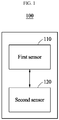
- FIG. 1 is a view illustrating a lidar sensor 100 according to an embodiment of the present disclosure.
- the lidar sensor 100 aims to obtain a high-resolution distance image at a front side of a vehicle using light.
- the lidar sensor 100 roughly measures a distance in a direct manner, and then precisely measures a wide viewing angle (spatial resolution) in an indirect manner. Accordingly, an ideal lidar sensor may be realized.
- the lidar sensor 100 may include a first sensor 110 and a second sensor 120.
- the first sensor 110 roughly measures a distance to a target
- the second sensor 120 may control output of a transmission signal considering the measured distance and may measure a front including the target in high resolution using the controlled transmission signal.
- the first sensor 110 may measure distance in a direct manner.
- the first sensor 110 may measure a distance by irradiating a target with pulse-type light and measuring a time until the irradiated light is reflected by the target and returns.
- the first sensor 110 may include at least one light receiving element of an Avalanche Photodiode (APD) and a Single Photon Avalanche Diode (SPAD).
- APD Avalanche Photodiode
- SPAD Single Photon Avalanche Diode
- An SPAD may sense even a single photon, as the name implies, and send a digital pulse.
- the SPAD may measure a long distance due to small restriction on distance and is less affected by external light, such as sunlight, due to a wide dynamic range thereof.
- the second sensor 120 may measure a front in high resolution using an indirect manner. That is, the front may be measured at high resolution by measuring a phase difference between pulse-type light irradiated to the front and light reflected and returned after the irradiation, within a threshold range, based on the distance roughly measured by the first sensor 110.
- the second sensor 120 may measure distance by irradiating light after modulating the same, and then measuring a phase difference between the irradiated light and reflected light, without directly measuring time.
- the second sensor 120 does not require a digital converter for time measurement.
- the second sensor 120 does not require a separate memory because all time data for irradiated light pulses is not stored. That is, by using the second sensor 120, spatial resolution may be increased while using less system resources.
- the second sensor 120 may measure the front at a reference interval within a threshold range based on the measured distance.
- the lidar sensor 100 may further include a controller (not shown) configured to control at least one of an order, ratios, and operations of the distance (coarse) measured using the first sensor 110 and the distance (fine) measured using the second sensor 120 through a software.
- a controller not shown
- the controller may perform control such that a frame (assumed to be a D frame) measured in a direct manner and a frame (assumed to be an I frame) measured in an indirect manner are measured according to frame types.
- the measurement may be performed in order of D frame, I frame, D frame, and I frame.
- the controller may measure a distance of each of the measured frames using software.
- FIG. 2A is a view particularly illustrating a structure of a lidar sensor 200 wherein second sensors 220 adopting an indirect manner are disposed around a first sensor 210 adopting a direct manner.
- the first sensor 210 may first measure a rough distance to a target.
- the second sensors 220 may be disposed around the first sensor 210 and may measure a front including a target in high resolution using a transmission signal controlled according to the distance measured by the first sensor 210.
- the first sensor 210 may generate a control signal such that the second sensors 220 may control output of the transmission signal.
- a controller of the first sensor 210 generates a control signal corresponding to the measured distance and transmits the generated control signal to the second sensors 220 around the first sensor 210 such that the output of the transmission signal may be controlled.
- a ratio of the number of the second sensors to the number of the first sensor is 5 to 20.
- FIG. 2B is a view more particularly illustrating a first sensor 230 adopting a direct manner.
- the first sensor 230 adopting a direct manner may include an SPAD, an ROIC, and a controller.
- the first sensor 230 may include at least one light receiving element of an Avalanche Photodiode (APD) and a Single Photon Avalanche Diode (SPAD).
- APD Avalanche Photodiode
- SPAD Single Photon Avalanche Diode
- An SPAD may respond even upon receiving a single photon and send a digital pulse.
- the SPAD may measure a long distance due to small restriction on a distance and is less affected by external light, such as sunlight, due to a wide dynamic range thereof.
- a ReadOut Integrated Circuit may be interpreted as an electrical multiplexer used to electrically interface with a hybrid flat array in a detector array.
- the ROIC includes an array of pixel circuits (single cells) capable of applying a reference voltage to each detector or measuring signals generated by incident electromagnetic energy.
- the ROIC may transmit signals recorded in a buffer to an external electronic circuit, or act as a photosensor and an infrared detector sensitive to ultraviolet.
- FIG. 2C is a view illustrating an embodiment of realizing a plurality of first sensors adopting a direct manner.
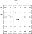
- two, four, or more D-TOFs may be disposed in a local pixel group to improve spatial resolution. That is, a plurality of D-TOFs may be disposed in one local pixel group.
- FIG. 3 is a view illustrating a lidar sensor 300 formed of a plurality of pixel groups.
- Each pixel group of the lidar sensor 300 may include a first pixel 310 measuring a distance to a target; and a plurality of second pixels 320 disposed around the first pixels and measuring a front including a target in high resolution using a controlled transmission signal.
- the lidar sensor 300 may further include a controller (not shown) configured to control output of a transmission signal considering the measured distance.
- the lidar sensor 300 may further include a calculator (not shown) configured to calculate sensing data by interpolating a distance measured by the first pixel 310 and a distance measured by the second pixels 320.
- the first pixel 310 may be interpreted as an SPAD-type pixel
- the second pixels 320 may be interpreted as lock-in pixels.
- a manner of arranging the SPAD-type pixel and the lock-in pixels may be varied.
- the lock-in pixels are disposed around the SPAD pixel.
- Each group is formed of the central SPAD pixel, and the lock-in pixels in a predetermined region.
- the groups may respectively be represented by local pixel groups #1 to #4.
- the lidar sensor 300 may be realized as a coarse-fine 2-step distance measurement structure wherein a rough distance value is first measured as a representative of surrounding pixels in a group through the SPAD pixel and an exact value of the distance value measured by the SPAD is precisely measured using the surrounding lock-in pixels.
- the second pixels 320 may measure the front at the reference interval within a threshold range based on the measured distance.
- the present disclosure is described in more detail with reference to FIG. 4 .
- FIG. 4 is a timing diagram 400 illustrating operation of a pixel structure according to an embodiment of the present disclosure.
- an SPAD of each local pixel group measures a rough distance though a portion corresponding to reference numeral 410, and a particular distance may be measured by control (gate control) a transmission signal to correspond to the measured distance through reference numeral 420 and applying to surrounding lock-in pixels.
- An SPAD pixel value may be obtained by interpolating the rough distance value and the distance value from the surrounding lock-in pixels.
- the lock-in pixels only detect distances in a pulse period, thus increasing efficiency.
- a rough distance value is first calculated at an interval of 1 m in an SPAD, and then local pixel group #1 may output 20 m and local pixel group #2 may output 25 m.
- lock-in pixels of local pixel group #1 measure a distance of 5 m at an interval of 5 cm around 20 m, and may calculate a distance of 17.5 m to 22.5 m at an interval of 5 cm from the two values.
- lock-in pixels of local pixel group #2 measure a distance of 5 m at an interval of 5 cm around 25 m, and may calculate a distance of 22.5 m to 27.5 m at an interval of 5 cm from the two values.
- FIG. 5 is a timing diagram 500 illustrating in-phase and an out-of-phase operation so as to suppress external light according to an embodiment of the present disclosure.
- Second pixels include a drain node, and a controller may turn on the drain node to remove electrons generated by external light when a transmission signal is not turned on by external light.
- vulnerability to external light as a drawback of a lock-in pixel, may be improved.
- the in-phase and the out-of-phase of FIG. 5 may correspond to gates 1 and 2 of FIG. 4 .
- the lock-in pixel is vulnerable to external light because a pulse wavelength of light reflected and returned is very short, but sunlight is continuously incident on the pixel, generating electrons.
- the lidar sensor according to the present disclosure may add a drain node to the lock-in pixels and, when a transmission signal is not turned on (when the in-phase or the out-of-phase is 0), may turn on a signal by a drain node to remove electrons generated by external light.
- a light pulse is irradiated once every 333 ns, and external light is incident on the light receiving element for 333ns.
- reflected light has a pulse of 10 ns, so that the ratio of external light incidence time to reflected light incidence time is 333 : 10.
- an incidence time of external light may be reduced to 20 ns using the drain node, so that the ratio of external light incidence time to reflected light incidence time is 20 : 10. Accordingly, a 15 times higher external light removal effect may be provided.
- the pulse width may be adjusted according to situation because there is a trade-off relationship between the maximum distance and the accuracy.
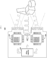
- FIG. 6 is a view illustrating an embodiment of using two or more sensors so as to provide a viewing angle required in a lidar sensor for vehicles.
- two or more sensors 620 and 630 may be used. Operation of each of the sensors 620 and 630 may be appropriately controlled through an FPGA controller 610.
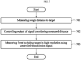
- FIG. 7 is a view illustrating a method of operating a lidar sensor according to an embodiment of the present disclosure.
- a distance to a target may be measured (step 701).
- the method of operating the lidar sensor according to an aspect of the present disclosure is characterized by, so as to measure a distance to the target, measuring a time until pulse-type light irradiated to the target is reflected by the target and returns, and measuring the distance based on the measured time.
- the method of operating the lidar sensor according to an embodiment of the present disclosure is characterized by controlling output of a transmission signal considering the measured distance (step 702).
- the method of operating the lidar sensor according to an embodiment of the present disclosure is characterized by measuring a front including the target in high resolution using the controlled transmission signal (step 703).
- the method of operating the lidar sensor according to an aspect of the present disclosure is characterized by, to measure a front in high resolution, measuring a phase difference between pulse-type light irradiated to the front and light reflected and returned after the irradiation and measuring the front in high resolution based on the measured phase difference.
- the method of operating the lidar sensor according to an aspect of the present disclosure is characterized by measuring the front at the reference interval within a threshold range based on the measured distance so as to measure the front in high resolution.
- a distance image at a front side of a vehicle may be obtained in a high resolution using light and, particularly, the high-resolution distance image may be obtained using a small space.
- a rough distance is measured in a direct manner and a wide viewing angle (spatial resolution) is measured in an indirect manner, thereby realizing an ideal lidar sensor.
- reliability of a distance image may be improved by reducing influence due to vibration of a vehicle, and vulnerability to external light may be addressed.
- a distance image at a front side of a vehicle may be obtained in high resolution.
- an ideal lidar sensor may be realized by measuring a rough distance in a direct manner and measuring a wide viewing angle (spatial resolution) in an indirect manner.
- a high-resolution distance image may be obtained using a small storage space.
- reliability of a distance image may be increased by reducing influence due to vibration of a vehicle.
- vulnerability to external light may be addressed.
- the device described above may be implemented as a hardware component, a software component, and/or a combination of hardware components and software components.
- the device and components described in the embodiments may be implemented using one or more general-purpose computers or special-purpose computers, such as, for example, a processor, a controller, an arithmetic logic unit (ALU), a digital signal processor, a microcomputer, a field programmable array (FPA), a programmable logic unit (PLU), a microprocessor, or any other devices capable of executing and responding to instructions.
- the processing device may execute an operating system (OS) and one or more software applications running on the operating system.
- the processing device may access, store, manipulate, process, and generate data in response to execution of the software.
- OS operating system
- the processing device may access, store, manipulate, process, and generate data in response to execution of the software.
- the processing device may be described as being used singly, but those skilled in the art will recognize that the processing device may include a plurality of processing elements and a plurality of processing element types.
- the processing device may include a plurality of processors or one processor and one controller.
- Other processing configurations, such as a parallel processor, are also possible.
- Software may include a computer program, code, instructions, or a combination of one or more thereof, and may configure a processing device to operate as desired or may independently or collectively command to a processing device.
- Software and/or data may be permanently or temporarily embodied by any machine type, a component, a physical device, virtual equipment, computer storage media, a device, or a transmitted signal wave so as to be interpreted by a processing unit or be provided to the processing unit.
- Software may be distributed over a networked computer system and stored or executed in a distributed manner.
- Software and data may be stored on one or more computer readable recording media.
- Embodiments of the present invention can include a computer readable medium including program commands for executing operations implemented through various computers.
- the computer readable medium can store program commands, data files, data structures or combinations thereof.
- the program commands recorded in the medium may be specially designed and configured for the present invention or be known to those skilled in the field of computer software.
- Examples of a computer readable recording medium include magnetic media such as hard disks, floppy disks and magnetic tapes, optical media such as CD-ROMs and DVDs, magneto-optical media such as floptical disks, or hardware devices such as ROMs, RAMs and flash memories, which are specially configured to store and execute program commands.
- Examples of the program commands include a machine language code created by a compiler and a high-level language code executable by a computer using an interpreter and the like.
- the hardware devices may be configured to operate as one or more software modules to perform the operations of the embodiments, and vice versa.
Landscapes
- Physics & Mathematics (AREA)
- Engineering & Computer Science (AREA)
- Electromagnetism (AREA)
- Computer Networks & Wireless Communication (AREA)
- General Physics & Mathematics (AREA)
- Radar, Positioning & Navigation (AREA)
- Remote Sensing (AREA)
- Optical Radar Systems And Details Thereof (AREA)
Abstract
Description
- This application claims the priority benefit of Korean Patent Application No.
10-2017-0121038, filed on September 20, 2017 - The present disclosure relates to a lidar sensor for vehicles and a method of operating the same, particularly to a technical idea of first measuring a rough distance value to a target in a direct manner and precisely measuring an exact value of the measured rough distance value based on the measured rough distance value.
- A lidar sensor, which adopts a technique of measuring a distance using light, can be interpreted as the same as a laser radar.
- A laser radar can be considered as a radar developed by using a laser beam with properties similar to those of radio waves. Although lasers were originally developed for communication, lasers have been used for various purposes besides communication because lasers have both light and radio wave characteristics due to strong monochromaticity thereof.
- In particular, it is possible to measure distance because the speed of light is constant. Specifically, distance can be precisely measured by accurately measuring the time that light from the light source near a camera reflects back to the object, which is called Time-of-Flight (TOF) technology.
- TOF technology is broadly divided into two manners, i.e., a direct manner and an indirect manner.
- The direct manner is a manner of directly measuring the time between when pulse-type light is irradiated and when reflected light is received. Here, given the speed of light, accuracy can be improved when a pulse width is minimized.
- In addition, measured time is so short, i.e. a distance of 100 m is calculated as a TOF of 667 ns, that a precise time-to-digital converter should be required and the sensitivity of a light receiving element should be very high. To reduce the uncertainty in the depth measurement, a light receiving element of a sensor used in general cameras measures received light for a long time of about 30 ms and the most reliable TOF value is chosen by digital processing such as histogramming.
- Accordingly, in a direct manner, an Avalanche Photodiode (APD) or a Single Photon Avalanche Diode (SPAD) may be used as a light receiving element.
- An SPAD can respond even upon receiving a single photon, as the name implies, and send a digital pulse. This method is advantageous in that it is theoretically possible to measure a long distance because there is no restriction on distance and resistance to external light, such as sunlight, is high due to a wide dynamic range of an element.
- However, since an SPAD is larger than a general photodiode and requires a large memory to digitize and store the time between the pulse of the light irradiated by data and the SPAD reaction output pulse, there are difficulties in realizing a high spatial resolution.
- On the other hand, a lidar sensor used in vehicles should have high resolution in that all images at the front side of a vehicle are obtained. Recently, various technologies have been developed to improve the resolution of a lidar sensor for vehicles. Lidar sensors under development or commercialized require a driver to rotate a sensor to improve resolution. However, when the driver for rotating the sensor is mounted on a vehicle, it is easily affected by vibration and thus it is difficult to obtain a reliable result.
- An indirect manner is a manner of calculating distance by measuring a phase difference between light irradiated after modulation and the reflected light and without directly measuring the time.
- Accordingly, a digital converter for time measurement is not necessary and, since all time data for light pulses irradiated is not stored, memory is not necessary. Accordingly, a lidar sensor adopting this manner is smaller than that adopting a direct manner. Therefore, it is possible to increase spatial resolution. Nevertheless, the in-direct manner is only capable of measuring a distance corresponding to the period of a modulated wave, and has a limit of being vulnerable to external light.
-
- Korean Patent Application Publication No.
2010-0011676 - Korean Patent Application Publication No.
2016-0142839 - Therefore, the present invention has been made in view of the above problems, and it is one object of the present invention to provide an ideal lidar sensor configured to measure a rough distance in a direct manner and measure a wide viewing angle (spatial resolution) in an indirect manner.
- It is another object of the present invention to obtain a high-resolution distance image at a front side of a vehicle using light.
- It is another object of the present invention to obtain a high-resolution distance image using a small storage space.
- It is another object of the present invention to increase reliability of a distance image by reducing influence due to vibration of a vehicle.
- It is yet another object of the present invention to address vulnerability to external light.
- In accordance with an aspect of the present invention, the above and other objects can be accomplished by the provision of a lidar sensor including a first sensor configured to measure a distance to a target; and a second sensor configured to control output of a transmission signal considering the measured distance and measure a front including the target using the controlled transmission signal in high resolution.
- The first sensor according to an embodiment of the present disclosure may measure a time until pulse-type light irradiated to the target is reflected by the target and is returned to measure the distance.
- The first sensor according to an embodiment of the present disclosure may include at least one light receiving element of an Avalanche Photodiode (APD) and a Single Photon Avalanche Diode (SPAD).
- The second sensor according to an embodiment of the present disclosure may measure a phase difference between the pulse-type light irradiated to the front and the light reflected and returned after the irradiation to measure the front in high resolution.
- The second sensor according to an embodiment of the present disclosure may measure the front at a reference interval within a threshold range based on the measured distance.
- In accordance with another aspect of the present invention, there is provided a lidar sensor including a first pixel configured to measure a distance to a target; a controller configured to control output of a transmission signal considering the measured distance; and a plurality of second pixels configured to measure a front including the target in high resolution using the controlled transmission signal.
- The lidar sensor according to an embodiment of the present disclosure may further include a calculator configured to calculate sensing data by interpolating the distance measured by the first pixel and a distance measured by the
second pixels 320. - The second pixels according to an embodiment of the present disclosure may measure the front at a reference interval within a threshold range based on the measured distance.
- The second pixels according to an embodiment of the present disclosure may include a drain node, and the controller may turn on the drain node to remove electrons generated by external light when the transmission signal is not turned on by the external light.
- In accordance with yet another aspect of the present invention there is provided a method of operating a lidar sensor, the method including measuring a distance to a target; controlling output of a transmission signal considering the measured distance; and measuring a front including the target in high resolution using the controlled transmission signal.
- The measuring of the distance to the target according to an embodiment of the present disclosure may include measuring a time until pulse-type light irradiated to the target is reflected by the target and is returned; and measuring the distance based on the measured time.
- The measuring of the front according to an embodiment of the present disclosure may include measuring a phase difference between pulse-type light irradiated to the front and light reflected and returned after the irradiation; and measuring the front in high resolution based on the measured phase difference.
- The measuring of the front according to an embodiment of the present disclosure may include measuring the front at a reference interval within a threshold range based on the measured distance.
- The above and other objects, features and other advantages of the present disclosure will be more clearly understood from the following detailed description taken in conjunction with the accompanying drawings, in which:
-
FIG. 1 is a view illustrating a lidar sensor according to an embodiment of the present disclosure; -
FIG. 2A is a view particularly illustrating a structure of a lidar sensor wherein second sensors adopting an indirect manner are disposed around a first sensor adopting a direct manner; -
FIG. 2B is a view more particularly illustrating a first sensor adopting a direct manner; -
FIG. 2C is a view illustrating an embodiment of realizing a plurality of first sensors adopting a direct manner; -
FIG. 3 is a view illustrating a lidar sensor formed of a plurality of pixel groups; -
FIG. 4 is a timing diagram illustrating operation of a pixel structure according to an embodiment of the present disclosure; -
FIG. 5 is a timing diagram illustrating in-phase and an out-of-phase operation so as to suppress external light according to an embodiment of the present disclosure; -
FIG. 6 is a view illustrating an embodiment of using two or more sensors so as to provide a viewing angle required in a lidar sensor for vehicles; and -
FIG. 7 is a view illustrating a method of operating a lidar sensor according to an embodiment of the present disclosure. - Specific structural or functional descriptions of embodiments according to the concepts of the present invention disclosed herein are illustrated for the purpose of describing embodiments only in accordance with the concepts of the present invention, and the embodiments according to the concepts may be implemented in various forms and the scope of the present invention is not limited to the embodiments described herein.
- Embodiments in accordance with the concepts of the present invention are capable of various modifications and may take various forms, so that the embodiments are illustrated in the drawings and described in detail herein. It should be understood, however, that the intention is not to limit the embodiments according to the concepts of the present invention to the specific disclosed embodiments, but includes changes, equivalents, or alternatives falling within the spirit and scope of the present invention.
- It will be understood that, although the terms first, second, third etc. may be used herein to describe various components, these components should not be limited by these terms. These terms are only used to distinguish one component from another component. For example, a first element may be termed a second element and a second element may be termed a first element without departing from the teachings of the present invention.
- It will be understood that when an element, such as a layer, a region, or a substrate, is referred to as being "on", "connected to" or "coupled to" another element, it may be directly on, connected or coupled to the other element or intervening elements may be present. In contrast, when an element is referred to as being "directly on," "directly connected to" or "directly coupled to" another element or layer, there are no intervening elements or layers present. Other words used to describe the relationship between elements or layers should be interpreted in a like fashion (e.g., "between," versus "directly between," "adjacent," versus "directly adjacent," etc.).
- The terminology used herein is for the purpose of describing particular embodiments only and is not intended to be limiting of the inventive concept. As used herein, the singular forms "a," "an" and "the" are intended to include the plural forms as well, unless the context clearly indicates otherwise. It will be further understood that the terms "comprises" and/or "comprising" when used in this specification, specify the presence of stated features, integers, steps, operations, elements, and/or components, but do not preclude the presence or addition of one or more other features, integers, steps, operations, elements, components, and/or groups thereof
- Unless otherwise defined, all terms (including technical and scientific terms) used herein have the same meaning as commonly understood by one of ordinary skill in the art to which this inventive concept belongs. It will be further understood that terms, such as those defined in commonly used dictionaries, should be interpreted as having a meaning that is consistent with their meaning in the context of the relevant art and will not be interpreted in an idealized or overly formal sense unless expressly so defined herein.
- The present invention will now be described more fully with reference to the accompanying drawings, in which exemplary embodiments of the invention are shown. This invention may, however, be embodied in many different forms and should not be construed as limited to the exemplary embodiments set forth herein. Like reference numerals in the drawings denote like elements.
-
FIG. 1 is a view illustrating alidar sensor 100 according to an embodiment of the present disclosure. - The
lidar sensor 100 according to an embodiment of the present disclosure aims to obtain a high-resolution distance image at a front side of a vehicle using light. - To accomplish this, the
lidar sensor 100 according to an embodiment of the present disclosure roughly measures a distance in a direct manner, and then precisely measures a wide viewing angle (spatial resolution) in an indirect manner. Accordingly, an ideal lidar sensor may be realized. - In particular, the
lidar sensor 100 according to an embodiment of the present disclosure may include afirst sensor 110 and asecond sensor 120. - The
first sensor 110 according to an embodiment of the present disclosure roughly measures a distance to a target, and thesecond sensor 120 may control output of a transmission signal considering the measured distance and may measure a front including the target in high resolution using the controlled transmission signal. - To accomplish this, the
first sensor 110 may measure distance in a direct manner. In particular, thefirst sensor 110 may measure a distance by irradiating a target with pulse-type light and measuring a time until the irradiated light is reflected by the target and returns. - In the case of a direct manner, accuracy increases as pulse width decreases, considering a speed of light. In addition, measured time is so short, i.e. a distance of 100 m is calculated as a TOF of 667 ns, that a precise time-to-digital converter should be required and the sensitivity of a light receiving element used in the
first sensor 110 should be much higher than a standard value. Accordingly, thefirst sensor 110 may include at least one light receiving element of an Avalanche Photodiode (APD) and a Single Photon Avalanche Diode (SPAD). - An SPAD may sense even a single photon, as the name implies, and send a digital pulse. In addition, the SPAD may measure a long distance due to small restriction on distance and is less affected by external light, such as sunlight, due to a wide dynamic range thereof.
- Meanwhile, the
second sensor 120 may measure a front in high resolution using an indirect manner. That is, the front may be measured at high resolution by measuring a phase difference between pulse-type light irradiated to the front and light reflected and returned after the irradiation, within a threshold range, based on the distance roughly measured by thefirst sensor 110. - The
second sensor 120 may measure distance by irradiating light after modulating the same, and then measuring a phase difference between the irradiated light and reflected light, without directly measuring time. - Accordingly, the
second sensor 120 does not require a digital converter for time measurement. In addition, thesecond sensor 120 does not require a separate memory because all time data for irradiated light pulses is not stored. That is, by using thesecond sensor 120, spatial resolution may be increased while using less system resources. - The
second sensor 120 according to an embodiment of the present disclosure may measure the front at a reference interval within a threshold range based on the measured distance. - The
lidar sensor 100 according to an embodiment of the present disclosure may further include a controller (not shown) configured to control at least one of an order, ratios, and operations of the distance (coarse) measured using thefirst sensor 110 and the distance (fine) measured using thesecond sensor 120 through a software. - For example, the controller according to an embodiment of the present disclosure may perform control such that a frame (assumed to be a D frame) measured in a direct manner and a frame (assumed to be an I frame) measured in an indirect manner are measured according to frame types. Here, the measurement may be performed in order of D frame, I frame, D frame, and I frame.
- Subsequently, the controller may measure a distance of each of the measured frames using software.
-
FIG. 2A is a view particularly illustrating a structure of alidar sensor 200 whereinsecond sensors 220 adopting an indirect manner are disposed around afirst sensor 210 adopting a direct manner. - The
first sensor 210 may first measure a rough distance to a target. - The
second sensors 220 may be disposed around thefirst sensor 210 and may measure a front including a target in high resolution using a transmission signal controlled according to the distance measured by thefirst sensor 210. Here, thefirst sensor 210 may generate a control signal such that thesecond sensors 220 may control output of the transmission signal. To accomplish this, a controller of thefirst sensor 210 generates a control signal corresponding to the measured distance and transmits the generated control signal to thesecond sensors 220 around thefirst sensor 210 such that the output of the transmission signal may be controlled. - A ratio of the number of the second sensors to the number of the first sensor is 5 to 20.
-
FIG. 2B is a view more particularly illustrating afirst sensor 230 adopting a direct manner. - The
first sensor 230 adopting a direct manner may include an SPAD, an ROIC, and a controller. - The
first sensor 230 may include at least one light receiving element of an Avalanche Photodiode (APD) and a Single Photon Avalanche Diode (SPAD). - An SPAD may respond even upon receiving a single photon and send a digital pulse. In addition, the SPAD may measure a long distance due to small restriction on a distance and is less affected by external light, such as sunlight, due to a wide dynamic range thereof.
- A ReadOut Integrated Circuit (ROIC) may be interpreted as an electrical multiplexer used to electrically interface with a hybrid flat array in a detector array. In addition, the ROIC includes an array of pixel circuits (single cells) capable of applying a reference voltage to each detector or measuring signals generated by incident electromagnetic energy. In addition, the ROIC may transmit signals recorded in a buffer to an external electronic circuit, or act as a photosensor and an infrared detector sensitive to ultraviolet.
-
FIG. 2C is a view illustrating an embodiment of realizing a plurality of first sensors adopting a direct manner. - More particularly, as indicated by
reference number 240, two, four, or more D-TOFs may be disposed in a local pixel group to improve spatial resolution. That is, a plurality of D-TOFs may be disposed in one local pixel group. -
FIG. 3 is a view illustrating alidar sensor 300 formed of a plurality of pixel groups. - Each pixel group of the
lidar sensor 300 according to an embodiment of the present disclosure may include afirst pixel 310 measuring a distance to a target; and a plurality ofsecond pixels 320 disposed around the first pixels and measuring a front including a target in high resolution using a controlled transmission signal. In addition, thelidar sensor 300 may further include a controller (not shown) configured to control output of a transmission signal considering the measured distance. Further, thelidar sensor 300 may further include a calculator (not shown) configured to calculate sensing data by interpolating a distance measured by thefirst pixel 310 and a distance measured by thesecond pixels 320. - For example, the
first pixel 310 may be interpreted as an SPAD-type pixel, and thesecond pixels 320 may be interpreted as lock-in pixels. - A manner of arranging the SPAD-type pixel and the lock-in pixels may be varied. Preferably, the lock-in pixels are disposed around the SPAD pixel.
- Each group is formed of the central SPAD pixel, and the lock-in pixels in a predetermined region. The groups may respectively be represented by local
pixel groups # 1 to #4. - Since, in the case of general images, many signals are present in low frequency bands, distances close to each other are very likely to have a similar value.
- The
lidar sensor 300 may be realized as a coarse-fine 2-step distance measurement structure wherein a rough distance value is first measured as a representative of surrounding pixels in a group through the SPAD pixel and an exact value of the distance value measured by the SPAD is precisely measured using the surrounding lock-in pixels. - For example, the
second pixels 320 may measure the front at the reference interval within a threshold range based on the measured distance. Hereinafter, the present disclosure is described in more detail with reference toFIG. 4 . -
FIG. 4 is a timing diagram 400 illustrating operation of a pixel structure according to an embodiment of the present disclosure. - Referring to the timing diagram 400, an SPAD of each local pixel group measures a rough distance though a portion corresponding to reference numeral 410, and a particular distance may be measured by control (gate control) a transmission signal to correspond to the measured distance through
reference numeral 420 and applying to surrounding lock-in pixels. - An SPAD pixel value may be obtained by interpolating the rough distance value and the distance value from the surrounding lock-in pixels.
- In accordance with the timing diagram 400, the lock-in pixels only detect distances in a pulse period, thus increasing efficiency.
- For example, when a total detection distance is 50 m, a rough distance value is first calculated at an interval of 1 m in an SPAD, and then local
pixel group # 1 may output 20 m and localpixel group # 2 may output 25 m. - Subsequently, lock-in pixels of local
pixel group # 1 measure a distance of 5 m at an interval of 5 cm around 20 m, and may calculate a distance of 17.5 m to 22.5 m at an interval of 5 cm from the two values. - In addition, lock-in pixels of local
pixel group # 2 measure a distance of 5 m at an interval of 5 cm around 25 m, and may calculate a distance of 22.5 m to 27.5 m at an interval of 5 cm from the two values. -
FIG. 5 is a timing diagram 500 illustrating in-phase and an out-of-phase operation so as to suppress external light according to an embodiment of the present disclosure. - Second pixels include a drain node, and a controller may turn on the drain node to remove electrons generated by external light when a transmission signal is not turned on by external light.
- In accordance with an embodiment of the present disclosure, vulnerability to external light, as a drawback of a lock-in pixel, may be improved.
- The in-phase and the out-of-phase of
FIG. 5 may correspond togates FIG. 4 . - The lock-in pixel is vulnerable to external light because a pulse wavelength of light reflected and returned is very short, but sunlight is continuously incident on the pixel, generating electrons.
- However, the lidar sensor according to the present disclosure may add a drain node to the lock-in pixels and, when a transmission signal is not turned on (when the in-phase or the out-of-phase is 0), may turn on a signal by a drain node to remove electrons generated by external light.
- For example, to measure a distance of about 50 m, a light pulse is irradiated once every 333 ns, and external light is incident on the light receiving element for 333ns.
- Here, when a pulse wavelength of irradiated light is 10 ns, reflected light has a pulse of 10 ns, so that the ratio of external light incidence time to reflected light incidence time is 333 : 10.
- However, according to the present disclosure, an incidence time of external light may be reduced to 20 ns using the drain node, so that the ratio of external light incidence time to reflected light incidence time is 20 : 10. Accordingly, a 15 times higher external light removal effect may be provided.
- In addition, since a pulse of irradiated light is short, an average intensity is not greatly affected although intensity of light is increased. Accordingly, eye safety is not affected.
- Theoretically, when a pulse is short, a distance that the lock-in pixels detect is small. However, the pulse width may be adjusted according to situation because there is a trade-off relationship between the maximum distance and the accuracy.
-
FIG. 6 is a view illustrating an embodiment of using two or more sensors so as to provide a viewing angle required in a lidar sensor for vehicles. - To provide a wide viewing angle required in a lidar sensor for vehicles, two or
more sensors sensors FPGA controller 610. -
FIG. 7 is a view illustrating a method of operating a lidar sensor according to an embodiment of the present disclosure. - By the method of operating the lidar sensor according to an embodiment of the present disclosure, a distance to a target may be measured (step 701).
- For example, the method of operating the lidar sensor according to an aspect of the present disclosure is characterized by, so as to measure a distance to the target, measuring a time until pulse-type light irradiated to the target is reflected by the target and returns, and measuring the distance based on the measured time.
- Next, the method of operating the lidar sensor according to an embodiment of the present disclosure is characterized by controlling output of a transmission signal considering the measured distance (step 702).
- The method of operating the lidar sensor according to an embodiment of the present disclosure is characterized by measuring a front including the target in high resolution using the controlled transmission signal (step 703).
- The method of operating the lidar sensor according to an aspect of the present disclosure is characterized by, to measure a front in high resolution, measuring a phase difference between pulse-type light irradiated to the front and light reflected and returned after the irradiation and measuring the front in high resolution based on the measured phase difference.
- Here, the method of operating the lidar sensor according to an aspect of the present disclosure is characterized by measuring the front at the reference interval within a threshold range based on the measured distance so as to measure the front in high resolution.
- In conclusion, in accordance with the present disclosure, a distance image at a front side of a vehicle may be obtained in a high resolution using light and, particularly, the high-resolution distance image may be obtained using a small space. For example, a rough distance is measured in a direct manner and a wide viewing angle (spatial resolution) is measured in an indirect manner, thereby realizing an ideal lidar sensor. In addition, in accordance with the present disclosure, reliability of a distance image may be improved by reducing influence due to vibration of a vehicle, and vulnerability to external light may be addressed.
- As apparent from the above description, in accordance with an embodiment of the present disclosure, a distance image at a front side of a vehicle may be obtained in high resolution.
- In accordance with an embodiment of the present disclosure, an ideal lidar sensor may be realized by measuring a rough distance in a direct manner and measuring a wide viewing angle (spatial resolution) in an indirect manner.
- In accordance with an embodiment of the present disclosure, a high-resolution distance image may be obtained using a small storage space.
- In accordance with an embodiment of the present disclosure, reliability of a distance image may be increased by reducing influence due to vibration of a vehicle.
- In accordance with an embodiment of the present disclosure, vulnerability to external light may be addressed.
- The device described above may be implemented as a hardware component, a software component, and/or a combination of hardware components and software components. For example, the device and components described in the embodiments may be implemented using one or more general-purpose computers or special-purpose computers, such as, for example, a processor, a controller, an arithmetic logic unit (ALU), a digital signal processor, a microcomputer, a field programmable array (FPA), a programmable logic unit (PLU), a microprocessor, or any other devices capable of executing and responding to instructions. The processing device may execute an operating system (OS) and one or more software applications running on the operating system. In addition, the processing device may access, store, manipulate, process, and generate data in response to execution of the software. For ease of understanding, the processing device may be described as being used singly, but those skilled in the art will recognize that the processing device may include a plurality of processing elements and a plurality of processing element types. For example, the processing device may include a plurality of processors or one processor and one controller. Other processing configurations, such as a parallel processor, are also possible.
- Software may include a computer program, code, instructions, or a combination of one or more thereof, and may configure a processing device to operate as desired or may independently or collectively command to a processing device. Software and/or data may be permanently or temporarily embodied by any machine type, a component, a physical device, virtual equipment, computer storage media, a device, or a transmitted signal wave so as to be interpreted by a processing unit or be provided to the processing unit. Software may be distributed over a networked computer system and stored or executed in a distributed manner. Software and data may be stored on one or more computer readable recording media.
- Embodiments of the present invention can include a computer readable medium including program commands for executing operations implemented through various computers. The computer readable medium can store program commands, data files, data structures or combinations thereof. The program commands recorded in the medium may be specially designed and configured for the present invention or be known to those skilled in the field of computer software. Examples of a computer readable recording medium include magnetic media such as hard disks, floppy disks and magnetic tapes, optical media such as CD-ROMs and DVDs, magneto-optical media such as floptical disks, or hardware devices such as ROMs, RAMs and flash memories, which are specially configured to store and execute program commands. Examples of the program commands include a machine language code created by a compiler and a high-level language code executable by a computer using an interpreter and the like. The hardware devices may be configured to operate as one or more software modules to perform the operations of the embodiments, and vice versa.
- Although the present invention has been described through limited embodiments and figures, the present invention is not intended to be limited to the embodiments. Those skilled in the art will appreciate that various modifications, additions and substitutions are possible, without departing from the scope and spirit of the invention. For example, although the described techniques are performed in a different order from the described method, and/or constituents, such as the described systems, structures, devices, and circuits, are combined in different manners and forms from the described method or substituted or replaced by other constituents or equivalents, appropriate results can be achieved.
- It should be understood, therefore, that there is no intent to limit the invention to the embodiments disclosed, rather, the invention is to cover all modifications, equivalents, and alternatives falling within the spirit and scope of the invention as defined by the claims.
Claims (14)
- A lidar sensor, comprising:a first sensor configured to measure a distance to a target; anda second sensor configured to control output of a transmission signal considering the measured distance and measure a front comprising the target using the controlled transmission signal in high resolution.
- The lidar sensor according to claim 1, wherein the first sensor measures a time until pulse-type light irradiated to the target is reflected by the target and is returned to measure the distance.
- The lidar sensor according to any preceding claim, wherein the first sensor comprises at least one light receiving element of an Avalanche Photodiode (APD) and a Single Photon Avalanche Diode (SPAD).
- The lidar sensor according to any preceding claim, wherein the second sensor measures a phase difference between the pulse-type light irradiated to the front and the light reflected and returned after the irradiation to measure the front in high resolution.
- The lidar sensor according to any preceding claim, wherein the second sensor measures the front at a reference interval within a threshold range based on the measured distance.
- The lidar sensor according to any preceding claim, wherein a ratio of the first sensor is 5 to 20.
- The lidar sensor according to any preceding claim, further comprising a controller configured to control at least one of an order, a ratio, and an operation of the distance (coarse) measured using the first sensor and the distance (fine) measured using the second sensor through a software.
- A lidar sensor, comprising:a first pixel configured to measure a distance to a target;a controller configured to control output of a transmission signal considering the measured distance; anda plurality of second pixels configured to measure a front comprising the target in high resolution using the controlled transmission signal.
- The lidar sensor according to claim 8, wherein the first pixel measures the distance to the target using at least one light receiving element of an Avalanche Photodiode (APD) and a Single Photon Avalanche Diode (SPAD).
- The lidar sensor according to claims 8 or 9, further comprising a calculator configured to calculate sensing data by interpolating the distance measured by the first pixel and a distance measured by the second pixels 320.
- The lidar sensor according to any of claims 8 to 10, wherein the second pixels measure the front at a reference interval within a threshold range based on the measured distance.
- The lidar sensor according to any of claims 8 to 11, wherein the second pixels comprise a drain node, and the controller turns on the drain node to remove electrons generated by external light when the transmission signal is not turned on by the external light.
- The lidar sensor according to any of claims 8 to 12, wherein a ratio of the first pixel is 5 to 20.
- A method of operating a lidar sensor, the method comprising:measuring a time until pulse-type light irradiated to the target is reflected by the target and is returned;measuring the distance based on the measured time;controlling output of a transmission signal considering the measured distance;measuring a front comprising the target in high resolution using the controlled transmission signal,wherein the measuring of the front comprises:measuring a phase difference between pulse-type light irradiated to the front and light reflected and returned after the irradiation;measuring the front in high resolution based on the measured phase difference; and measuring the front at a reference interval within a threshold range based on the measured distance.
Applications Claiming Priority (1)
| Application Number | Priority Date | Filing Date | Title |
|---|---|---|---|
| KR1020170121038A KR102016942B1 (en) | 2017-09-20 | 2017-09-20 | Lidar sensor for vehicle and method of the same |
Publications (1)
| Publication Number | Publication Date |
|---|---|
| EP3460517A1 true EP3460517A1 (en) | 2019-03-27 |
Family
ID=62091754
Family Applications (1)
| Application Number | Title | Priority Date | Filing Date |
|---|---|---|---|
| EP18170086.5A Withdrawn EP3460517A1 (en) | 2017-09-20 | 2018-04-30 | Lidar sensor for vehicles and method of operating the same |
Country Status (3)
| Country | Link |
|---|---|
| US (1) | US10935658B2 (en) |
| EP (1) | EP3460517A1 (en) |
| KR (1) | KR102016942B1 (en) |
Families Citing this family (16)
| Publication number | Priority date | Publication date | Assignee | Title |
|---|---|---|---|---|
| US11556000B1 (en) | 2019-08-22 | 2023-01-17 | Red Creamery Llc | Distally-actuated scanning mirror |
| US12399279B1 (en) | 2016-02-15 | 2025-08-26 | Red Creamery Llc | Enhanced hybrid LIDAR with high-speed scanning |
| US12399278B1 (en) | 2016-02-15 | 2025-08-26 | Red Creamery Llc | Hybrid LIDAR with optically enhanced scanned laser |
| US12123950B2 (en) | 2016-02-15 | 2024-10-22 | Red Creamery, LLC | Hybrid LADAR with co-planar scanning and imaging field-of-view |
| DE102019122566A1 (en) | 2019-08-22 | 2021-02-25 | Valeo Schalter Und Sensoren Gmbh | Method for operating an optoelectronic detection device and optoelectronic detection device |
| KR20210150765A (en) * | 2020-06-04 | 2021-12-13 | 에스케이하이닉스 주식회사 | Image Sensing Device and Image photographing apparatus including the same |
| US20230213627A1 (en) * | 2020-06-18 | 2023-07-06 | NewSight Imaging Ltd. | A method and active pixel array for a time of flight detection |
| US20230307473A1 (en) * | 2020-07-17 | 2023-09-28 | Sony Semiconductor Solutions Corporation | Light receiving element, manufacturing method for same, and electronic device |
| KR102823325B1 (en) | 2020-07-20 | 2025-06-23 | 에스케이하이닉스 주식회사 | Image sensing device having protection device |
| KR102210601B1 (en) * | 2020-10-16 | 2021-02-02 | (주)카네비컴 | Lidar system for reducing power consumption and method of driving the same |
| KR102480883B1 (en) * | 2020-12-15 | 2022-12-26 | 연세대학교 산학협력단 | Lidar sensor for vehicle |
| KR20220141006A (en) * | 2021-04-12 | 2022-10-19 | 에스케이하이닉스 주식회사 | Image photographing apparatus |
| WO2024039160A1 (en) * | 2022-08-18 | 2024-02-22 | 삼성전자주식회사 | Lidar sensor based on itof sensor, and control method therefor |
| KR20240086393A (en) | 2022-12-09 | 2024-06-18 | 에스케이텔레콤 주식회사 | Light receiving module and lidar sensing device including the same |
| KR20250120114A (en) | 2024-02-01 | 2025-08-08 | 주식회사 솔리드뷰 | Lidar sensor modulating radiation time |
| WO2026010005A1 (en) * | 2024-07-04 | 2026-01-08 | 주식회사 엘엑스세미콘 | Tof sensor operable in various pixel driving methods and operating method thereof |
Citations (4)
| Publication number | Priority date | Publication date | Assignee | Title |
|---|---|---|---|---|
| WO2008152647A2 (en) * | 2007-06-15 | 2008-12-18 | Ben Gurion University Of The Negev Research And Development Authority | Three-dimensional imaging method and apparatus |
| KR20100011676A (en) | 2008-07-25 | 2010-02-03 | 삼성전자주식회사 | Image sensor and operating method for image sensor |
| KR20160142839A (en) | 2014-04-07 | 2016-12-13 | 삼성전자주식회사 | High resolution, high frame rate, low power image sensor |
| US20170052065A1 (en) * | 2015-08-20 | 2017-02-23 | Apple Inc. | SPAD array with gated histogram construction |
Family Cites Families (10)
| Publication number | Priority date | Publication date | Assignee | Title |
|---|---|---|---|---|
| KR19980072528A (en) * | 1997-03-06 | 1998-11-05 | 김영환 | Laser distance measuring device and its distance measuring control method using CCD camera |
| US6587072B1 (en) * | 2002-03-22 | 2003-07-01 | M/A-Com, Inc. | Pulse radar detection system |
| EP1521981B1 (en) * | 2002-07-15 | 2008-02-20 | Matsushita Electric Works, Ltd. | Light receiving device with controllable sensitivity and spatial information detecting apparatus using the same |
| JP2010127839A (en) * | 2008-11-28 | 2010-06-10 | Mitsubishi Electric Corp | Laser radar device |
| KR101333572B1 (en) * | 2011-12-28 | 2013-12-02 | 컴레이저 (주) | Ship Approach Warning System and Warning Method for Bridge Protect |
| JP6119232B2 (en) * | 2012-12-19 | 2017-04-26 | 株式会社ソシオネクスト | Distance measuring device and distance measuring method |
| KR20140144611A (en) * | 2013-06-11 | 2014-12-19 | 삼성테크윈 주식회사 | System for disabling object vehicle and operating method for thereof |
| KR102151708B1 (en) * | 2013-11-06 | 2020-09-03 | 현대모비스(주) | Vehicle Controlling Method and Apparatus therefor |
| KR20160075134A (en) * | 2014-12-19 | 2016-06-29 | 현대모비스 주식회사 | Radar system for the Vehicles |
| EP3070494B1 (en) * | 2015-03-18 | 2021-04-28 | Leica Geosystems AG | Electro-optical distance measuring method and electro-optical distance meter |
-
2017
- 2017-09-20 KR KR1020170121038A patent/KR102016942B1/en active Active
-
2018
- 2018-04-26 US US15/963,705 patent/US10935658B2/en active Active
- 2018-04-30 EP EP18170086.5A patent/EP3460517A1/en not_active Withdrawn
Patent Citations (4)
| Publication number | Priority date | Publication date | Assignee | Title |
|---|---|---|---|---|
| WO2008152647A2 (en) * | 2007-06-15 | 2008-12-18 | Ben Gurion University Of The Negev Research And Development Authority | Three-dimensional imaging method and apparatus |
| KR20100011676A (en) | 2008-07-25 | 2010-02-03 | 삼성전자주식회사 | Image sensor and operating method for image sensor |
| KR20160142839A (en) | 2014-04-07 | 2016-12-13 | 삼성전자주식회사 | High resolution, high frame rate, low power image sensor |
| US20170052065A1 (en) * | 2015-08-20 | 2017-02-23 | Apple Inc. | SPAD array with gated histogram construction |
Also Published As
| Publication number | Publication date |
|---|---|
| KR20190032789A (en) | 2019-03-28 |
| US10935658B2 (en) | 2021-03-02 |
| US20190086540A1 (en) | 2019-03-21 |
| KR102016942B1 (en) | 2019-09-02 |
Similar Documents
| Publication | Publication Date | Title |
|---|---|---|
| US10935658B2 (en) | Lidar sensor for vehicles and method of operating the same | |
| US20250138193A1 (en) | Processing system for lidar measurements | |
| EP3848722B1 (en) | Lidar device and method of operating the same | |
| US20200191959A1 (en) | Solid state light detection and ranging (lidar) system and system and method for improving solid state light detection and ranging (lidar) resolution | |
| US11175404B2 (en) | Lidar system and method of operating the lidar system comprising a gating circuit range-gates a receiver based on a range-gating waveform | |
| Niclass et al. | A 0.18-$\mu $ m CMOS SoC for a 100-m-Range 10-Frame/s 200$\,\times\, $96-Pixel Time-of-Flight Depth Sensor | |
| CN114930185B (en) | Active Depth Sensing Image Sensor | |
| EP3663792B1 (en) | Light detection and ranging device and method of driving the same | |
| US11808890B2 (en) | Distance measuring device and method of measuring distance by using the same | |
| US12487362B2 (en) | Configurable memory blocks for LIDAR measurements | |
| EP3602110B1 (en) | Time of flight distance measurement system and method | |
| CN112147595B (en) | Laser detection device, method and system | |
| US20220252730A1 (en) | Time-of-flight imaging apparatus and time-of-flight imaging method | |
| US12487341B2 (en) | Methods and systems for lidar walk error correction | |
| WO2023155093A1 (en) | Detection apparatus and detection method | |
| CN113933816B (en) | Methods for reading integrated circuits and determining the distance or speed of an object | |
| KR102480883B1 (en) | Lidar sensor for vehicle | |
| CN121254284A (en) | Laser radar control method, laser radar, terminal device and computer program product |
Legal Events
| Date | Code | Title | Description |
|---|---|---|---|
| PUAI | Public reference made under article 153(3) epc to a published international application that has entered the european phase |
Free format text: ORIGINAL CODE: 0009012 |
|
| STAA | Information on the status of an ep patent application or granted ep patent |
Free format text: STATUS: REQUEST FOR EXAMINATION WAS MADE |
|
| 17P | Request for examination filed |
Effective date: 20180430 |
|
| AK | Designated contracting states |
Kind code of ref document: A1 Designated state(s): AL AT BE BG CH CY CZ DE DK EE ES FI FR GB GR HR HU IE IS IT LI LT LU LV MC MK MT NL NO PL PT RO RS SE SI SK SM TR |
|
| AX | Request for extension of the european patent |
Extension state: BA ME |
|
| STAA | Information on the status of an ep patent application or granted ep patent |
Free format text: STATUS: EXAMINATION IS IN PROGRESS |
|
| 17Q | First examination report despatched |
Effective date: 20191211 |
|
| STAA | Information on the status of an ep patent application or granted ep patent |
Free format text: STATUS: THE APPLICATION HAS BEEN WITHDRAWN |
|
| 18W | Application withdrawn |
Effective date: 20220922 |