EP3460494B1 - A method and apparatus for automatic detection of a fault type - Google Patents
A method and apparatus for automatic detection of a fault type Download PDFInfo
- Publication number
- EP3460494B1 EP3460494B1 EP17193123.1A EP17193123A EP3460494B1 EP 3460494 B1 EP3460494 B1 EP 3460494B1 EP 17193123 A EP17193123 A EP 17193123A EP 3460494 B1 EP3460494 B1 EP 3460494B1
- Authority
- EP
- European Patent Office
- Prior art keywords
- fault
- detection apparatus
- field detection
- neural network
- power transmission
- Prior art date
- Legal status (The legal status is an assumption and is not a legal conclusion. Google has not performed a legal analysis and makes no representation as to the accuracy of the status listed.)
- Active
Links
Images
Classifications
-
- G—PHYSICS
- G01—MEASURING; TESTING
- G01R—MEASURING ELECTRIC VARIABLES; MEASURING MAGNETIC VARIABLES
- G01R31/00—Arrangements for testing electric properties; Arrangements for locating electric faults; Arrangements for electrical testing characterised by what is being tested not provided for elsewhere
- G01R31/08—Locating faults in cables, transmission lines, or networks
- G01R31/081—Locating faults in cables, transmission lines, or networks according to type of conductors
- G01R31/085—Locating faults in cables, transmission lines, or networks according to type of conductors in power transmission or distribution lines, e.g. overhead
-
- G—PHYSICS
- G01—MEASURING; TESTING
- G01R—MEASURING ELECTRIC VARIABLES; MEASURING MAGNETIC VARIABLES
- G01R31/00—Arrangements for testing electric properties; Arrangements for locating electric faults; Arrangements for electrical testing characterised by what is being tested not provided for elsewhere
- G01R31/50—Testing of electric apparatus, lines, cables or components for short-circuits, continuity, leakage current or incorrect line connections
- G01R31/52—Testing for short-circuits, leakage current or ground faults
-
- G—PHYSICS
- G06—COMPUTING OR CALCULATING; COUNTING
- G06N—COMPUTING ARRANGEMENTS BASED ON SPECIFIC COMPUTATIONAL MODELS
- G06N3/00—Computing arrangements based on biological models
- G06N3/02—Neural networks
- G06N3/04—Architecture, e.g. interconnection topology
- G06N3/044—Recurrent networks, e.g. Hopfield networks
-
- G—PHYSICS
- G06—COMPUTING OR CALCULATING; COUNTING
- G06N—COMPUTING ARRANGEMENTS BASED ON SPECIFIC COMPUTATIONAL MODELS
- G06N3/00—Computing arrangements based on biological models
- G06N3/02—Neural networks
- G06N3/04—Architecture, e.g. interconnection topology
- G06N3/044—Recurrent networks, e.g. Hopfield networks
- G06N3/0442—Recurrent networks, e.g. Hopfield networks characterised by memory or gating, e.g. long short-term memory [LSTM] or gated recurrent units [GRU]
-
- G—PHYSICS
- G06—COMPUTING OR CALCULATING; COUNTING
- G06N—COMPUTING ARRANGEMENTS BASED ON SPECIFIC COMPUTATIONAL MODELS
- G06N3/00—Computing arrangements based on biological models
- G06N3/02—Neural networks
- G06N3/04—Architecture, e.g. interconnection topology
- G06N3/045—Combinations of networks
-
- G—PHYSICS
- G06—COMPUTING OR CALCULATING; COUNTING
- G06N—COMPUTING ARRANGEMENTS BASED ON SPECIFIC COMPUTATIONAL MODELS
- G06N3/00—Computing arrangements based on biological models
- G06N3/02—Neural networks
- G06N3/04—Architecture, e.g. interconnection topology
- G06N3/0464—Convolutional networks [CNN, ConvNet]
-
- G—PHYSICS
- G06—COMPUTING OR CALCULATING; COUNTING
- G06N—COMPUTING ARRANGEMENTS BASED ON SPECIFIC COMPUTATIONAL MODELS
- G06N3/00—Computing arrangements based on biological models
- G06N3/02—Neural networks
- G06N3/08—Learning methods
-
- G—PHYSICS
- G06—COMPUTING OR CALCULATING; COUNTING
- G06N—COMPUTING ARRANGEMENTS BASED ON SPECIFIC COMPUTATIONAL MODELS
- G06N3/00—Computing arrangements based on biological models
- G06N3/02—Neural networks
- G06N3/08—Learning methods
- G06N3/09—Supervised learning
-
- H—ELECTRICITY
- H02—GENERATION; CONVERSION OR DISTRIBUTION OF ELECTRIC POWER
- H02H—EMERGENCY PROTECTIVE CIRCUIT ARRANGEMENTS
- H02H1/00—Details of emergency protective circuit arrangements
- H02H1/0092—Details of emergency protective circuit arrangements concerning the data processing means, e.g. expert systems, neural networks
-
- H—ELECTRICITY
- H02—GENERATION; CONVERSION OR DISTRIBUTION OF ELECTRIC POWER
- H02H—EMERGENCY PROTECTIVE CIRCUIT ARRANGEMENTS
- H02H3/00—Emergency protective circuit arrangements for automatic disconnection directly responsive to an undesired change from normal electric working condition with or without subsequent reconnection ; integrated protection
- H02H3/02—Details
- H02H3/04—Details with warning or supervision in addition to disconnection, e.g. for indicating that protective apparatus has functioned
-
- Y—GENERAL TAGGING OF NEW TECHNOLOGICAL DEVELOPMENTS; GENERAL TAGGING OF CROSS-SECTIONAL TECHNOLOGIES SPANNING OVER SEVERAL SECTIONS OF THE IPC; TECHNICAL SUBJECTS COVERED BY FORMER USPC CROSS-REFERENCE ART COLLECTIONS [XRACs] AND DIGESTS
- Y04—INFORMATION OR COMMUNICATION TECHNOLOGIES HAVING AN IMPACT ON OTHER TECHNOLOGY AREAS
- Y04S—SYSTEMS INTEGRATING TECHNOLOGIES RELATED TO POWER NETWORK OPERATION, COMMUNICATION OR INFORMATION TECHNOLOGIES FOR IMPROVING THE ELECTRICAL POWER GENERATION, TRANSMISSION, DISTRIBUTION, MANAGEMENT OR USAGE, i.e. SMART GRIDS
- Y04S10/00—Systems supporting electrical power generation, transmission or distribution
- Y04S10/50—Systems or methods supporting the power network operation or management, involving a certain degree of interaction with the load-side end user applications
- Y04S10/52—Outage or fault management, e.g. fault detection or location
Definitions
- the invention relates to a method and an apparatus for automatic detection of a fault type of a fault having occurred at power transmission lines of a power supply system.
- a power supply system can comprise several power transmission lines. Most power supply systems comprise 3-phased power transmission lines L1, L2, L3. During the distribution of electrical power in a power transmission system via the power transmission lines unexpected failures can occur due to various causes. For example, one or more current loops can comprise a short circuit caused by a falling tree or branch during a storm. Further, a power transmission loop might be interrupted when lightning strikes a pole. As such failures impact a reliable and safe operation of the power supply system they need to be detected and measures have to be taken to prevent a propagation of faults to the remaining power supply grid.
- DE 44 33 406 C1 discloses a distance protection unit for an electrical power supply net with a neural net arrangement connected over current and voltage converter and an ADC.
- the distance protection unit further comprises a fault determination unit with a single neural net that is trained by simulated current and/or voltage faults, which can occur within different overload states in the electrical power supply net. This training results in a predefined behavior where an output signal is provided for an already known fault.
- Document DE 43 33 260 A1 discloses an apparatus to generate a stimulate signal for a protection arrangement power supply net.
- an in-field detection apparatus comprising the features of claim 1.
- the invention provides according to the first aspect an in-field detection apparatus for automatic detection of a fault type of a fault having occurred at power transmission lines of a power supply system, said in-field detection apparatus comprising:
- the artificial neural network stored in the local memory of said in-field detection apparatus comprises a feed-forward neural network.
- the feed-forward neural network stored in the local memory of the in-field detection apparatus comprises a convolutional neural network.
- the artificial neural network stored in the local memory of the in-field detection apparatus comprises a recurrent neural network.
- the fault type detected by said in-field detection apparatus comprises a short circuit between power transmission lines and/or an interruption of a power transmission line.
- the preprocessing unit and the processing unit operate in real time to detect the fault type of the fault having occurred at a power transmission line of said power supply system.
- the artificial neural network executed by said processing unit comprises an input layer adapted to receive the normalized measured voltage and/or current raw data from said preprocessing unit, one or more hidden layers and an output layer adapted to output the fault type scores evaluated to detect the fault type of the occurred fault.
- the fault type scores comprise a probability that a fault of a predefined fault type has occurred.
- the preprocessing unit is adapted to normalize raw data of a measured fault record comprising voltage raw data of different voltage phases transported through corresponding power transmission lines, current raw data of associated electrical currents transported through the respective power transmission lines and current raw data of an electrical current flowing through earth.
- the voltage and/or current raw data of the measured fault record processed by said preprocessing unit comprises data samples measured by corresponding sensors within a time window having a predetermined window size.
- a database or an online stream of fault records with known fault types is provided and used to train the artificial neural network stored in the local memory of said in-field detection apparatus.
- the database of fault records comprises simulated fault records and/or fault records of historical faults having occurred at power transmission lines of said power supply system.
- the preprocessing unit is adapted to perform a Z-score or min-max normalization of measured voltage and/or current raw data of power transmission lines.
- countermeasures to remove the fault are initiated automatically by a controller depending on the detected fault type.
- the local memory of said in-field detection apparatus comprises a small memory space of less than 256 Megabyte.
- the invention provides according to a second aspect a method for automatic detection of a fault type comprising the features of claim 15.
- the invention provides according to the second aspect a method for automatic detection of a fault type of a fault having occurred at power transmission lines of a power supply system, the method comprising the steps of:
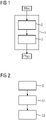
- an in-field detection apparatus 1 for automatic detection of a fault type comprises in the illustrated exemplary embodiment two main components, i.e. a preprocessing unit 2 and a processing unit 3.
- the in-field detection apparatus 1 can be provided for automatic detection of a fault type of a fault having occurred at power transmission lines of a power supply system.
- the in-field detection apparatus 1 as shown in Fig. 1 can be provided at a node of a power supply grid. Between the nodes of the power supply grid electric power transmission lines are provided for transporting electrical voltage and/or electrical currents.
- the power supply system can comprise in a possible embodiment three different phased power transmission lines L1, L2, L3.
- the preprocessing unit 2 receives a measured fault record including raw data.
- the raw data can comprise in a possible embodiment voltage raw data of different voltage phases transported through corresponding power transmission lines, current raw data of associated electrical currents transported through the respective power transmission lines and current raw data of an electric current flowing through earth.
- the preprocessing unit 2 is adapted to normalize the measured voltage raw data and/or current raw data of the power transmission lines as specified in the received fault record.
- the voltage and current raw data of the measured fault record processed by the preprocessing unit 2 can comprise data samples measured by corresponding sensors within a time window having a predetermined window size.
- the preprocessing unit 2 of the in-field detection apparatus 1 is adapted to perform a Z-score min-max normalization of the measured voltage and/or current raw data of the power transmission lines specified in the received fault records.
- the in-field detection apparatus 1 further comprises a processing unit 3 connected to the preprocessing unit 2.
- the processing unit 3 is configured to execute an artificial neural network ANN stored in a local memory of the in-field detection apparatus 1.
- the normalized voltage and/or current raw data is mapped to fault type scores of different predetermined fault types. Further, the fault type scores are evaluated by the processing unit 3 to detect the fault type of the occurred fault.
- the detected fault type of the occurred fault can be output by the processing unit 3.
- the artificial neural network used by the processing unit 3 can be stored in a possible embodiment in a local memory of the in-field detection apparatus 1.
- the local memory can form part of the in-field detection apparatus 1 or can be connected directly to the in-field detection apparatus 1.
- the artificial neural network ANN can comprise in a possible embodiment a feed-forward neural network, in particular a convolutional neural network CNN.
- the artificial neural network stored in the local memory of the in-field detection apparatus 1 can comprise a recurrent neural network RNN.
- a fault type detected by the in-field detection apparatus 1 can be a short circuit between at least two power transmission lines or an interruption of a power transmission line L.
- the preprocessing unit 2 as well as the processing unit 3 operate in real time to detect the fault type of a fault having occurred at at least one power transmission line of the power supply system.
- the artificial neural network ANN executed by the processing unit 3 comprises an input layer adapted to receive the normalized measured voltage and/or current raw data from the preprocessing unit 2. Further, the artificial neural network comprises one or more hidden layers and an output layer. The output layer is adapted to output the fault type scores which are evaluated to detect the fault type of the occurred fault. In a possible embodiment the fault type scores can comprise a probability that a fault of predefined fault type has occurred.
- the artificial neural network ANN used by the processing unit 3 can be trained with a set of data.
- a database or an online stream of fault records with known fault types can be used to train the artificial neural network stored in the local memory of the in-field detection apparatus 1 and used by the processing unit 3 to detect the fault type of the occurred fault.
- the database of fault records used for training the artificial network can comprise simulated fault records and/or fault records of historical faults having occurred in power transmission lines of the power supply system in the past.
- countermeasures to remove the detected fault can be initiated automatically by a controller depending on the detected fault type output by the processing unit 3 of the in-field detection apparatus 1.
- the artificial neural network ANN used by the processing unit 3 of the in-field apparatus 1 requires low storage resources.
- the local memory of the in-field detection apparatus 1 used for storing the artificial neural network ANN can comprise a small memory space of less than 256 Megabytes.
- the in-field detection apparatus 1 employs an artificial intelligence module to detect a number and identity of current loops of power transmission lines affected by an incident based on the received fault record. Any combination of loops (L1, L2, L3) and earth (E) can be affected by any given incident.
- the artificial intelligence module with the artificial neural network ANN can be trained in a possible embodiment on a combination of synthetic fault records that can be efficiently generated by existing simulation systems. Further, the fault records can also comprise real data samples of historical faults having occurred in the past. In this way the artificial neural network ANN learns to interpret patterns in the data which can be used to also process new previously unseen data samples or fault records.
- the artificial neural network ANN executed by the processing unit 3 comprises a higher performance than conventional rule-based systems.
- the performance of the artificial neural network ANN can be further improved by retraining it on a larger set of fault records with a minimal effort and can be implemented or deployed on extremely resource-limited devices.
- the data normalized by the preprocessing unit 2 can be passed through a network of weighted linear or non-linear functions which results in a set of values indicating a fault type wherein each detected fault type can be mapped to a specific combination of affected loops within the power transmission system.
- the artificial neural network ANN comprises at least one convolutional layer consisting of a number of local filters automatically extracting meaningful features from the input signals, followed by at least one fully connected layer connecting the flattened filter signals to a number of output nodes equaling the number of fault types.
- each output node of the output layer can correspond to a single specific fault type (e.g. L1, L1-L2, L1-L3, L2-L3, ..., L1-L2-L3-E) and the final fault type can be identified by selecting the output node with the maximum value associated.
- the weights of the artificial neural network ANN can be trained by sequentially passing data samples with a known fault type through the artificial neural network ANN and by comparing the generated output values with the occurred fault.
- the in-field detection apparatus 1 can use the artificial neural network ANN stored in a local memory as a fault classifier.
- the in-field detection apparatus comprising the preprocessing unit 2 and the processing unit 3 can be embedded in different kinds of in-field protection devices such as SIPROTEC having very limited computational and storage resources.
- SIPROTEC in-field protection devices
- the preprocessing and processing unit of the in-field detection apparatus 1 as illustrated in Fig. 1 requires very few storage resources and low computational resources. In a possible embodiment the number of weights in the artificial neural network ANN can be limited to further safe resources.
- Fig. 2 shows a flowchart of a possible exemplary embodiment of a method for automatic detection of a fault type or a fault having occurred at power transmission lines of a power supply system according to the second aspect of the present invention.
- the method comprises three main steps.
- first step S1 the measured voltage raw data and/or current raw data of the power transmission lines of the power supply system are normalized.
- This normalization can comprise a Z-score or min-max normalization of the measured voltage and/or current raw data.
- an artificial neural network ANN stored in a local memory of the in-field detection apparatus 1 is executed to map the normalized voltage and current raw data to fault type scores of different predefined fault types.
- a third step S3 the fault type scores are evaluated to detect the fault type of the occurred fault.
- the detected fault type can then be output via a user interface and/or data interface of the in-field detection apparatus 1 or for further processing and/or for triggering an automatic countermeasure to remove the detected fault type with the specific detected fault type.
- the artificial neural network ANN used in step S2 can be trained in a training procedure before initiating step S1.
- a database or an online stream of fault records with known fault types can be generated by existing simulation algorithms, while generalization capabilities of the module can depend on the number and variation of fault records it is trained on.
- the performance of the artificial neural network ANN can be increased by adding as many real fault records to the training data set as possible.
- the data set can be split into a training data set and a validation data set. The artificial neural network ANN can then be optimized on the training data and tested on the validation data set which is not used during training. Once training of the artificial neural network ANN has been completed, (i.e.
- the artificial neural network can be stored in the local memory of the in-field detection apparatus 1 for operation in the system.
- new data samples i.e. a fault record can be passed through the artificial neural network ANN without knowing the intended output value.
- the artificial neural network can be trained until the categorical cross entropy between the predicted function samples and real ones is minimized.
- the method and apparatus according to the present invention do not require any feature computation on the raw input signals as the artificial neural network ANN is capable of learning important characteristics directly in an end-to-end fashion.
- a conventional feature-based approach requires an extensive amount of domain understanding and manual effort to design good specific features which also bears a risk of missing important patterns that cannot be recognized in the defined feature set.
- the performance of the method and apparatus according to the present invention relies on the raw input data with a normalization step and can consequently easily be extended or improved by feeding additional simulated fault records or real fault records to the artificial neural network.
- the method and apparatus according to the present invention is data-driven. Consequently the artificial neural network ANN is continuously improved with more data or fault records.
- the method and apparatus according to the present invention is not rule-based and can therefore be more easily adapted to the respective use case without extensive of expert domain knowledge.
- the apparatus and method can be trained on simulated or real fault data.
- the method and apparatus do not require to compute domain-specific features as the features can be implicitly learned by the artificial neural network ANN.
- the artificial neural network ANN used by the method and apparatus according to the present invention comprises a deep neural network in particular a convolutional deep neural network.
- a further advantage of the method and apparatus according to the present invention is that new and improved versions of the artificial intelligence module can be generated autonomously, i.e. it is possible to retrain the module or artificial neural network on new/more data without any human interaction.
- the detected fault types can be output via an interface to a controller of the power supply system.
- the controller can evaluate the received fault type and trigger automatic countermeasures and/or inform a user via a user interface.
- countermeasures comprise an automatic shutdown of affected power transmission lines depending on the detected fault type.
- the controller of the system can activate a switching actuator via a control signal depending on the detected fault type of the occurred fault.
- the in-field detection apparatus can receive raw signals from every power transmission line in a given time interval of e.g. less than 20 ms.
- the method and apparatus according to the present invention operate in a preferred embodiment in real time so that countermeasures can be initiated or triggered very fast depending on the detected fault type.
- the method requires a very low computation time to detect the fault type comprising less than 200 ms.
- the artificial neural network ANN has a very small memory footprint and can be stored for instance in a small memory having a memory size of less than 256 Megabytes. Accordingly, the method and apparatus according to the present invention can be implemented on any kind of in-field detection apparatus even if this apparatus comprises only a small data memory and/or limited computation resources.
- the in-field detection apparatus 1 can be implemented on a SIPROTEC device of an electrical power supply system.
Landscapes
- Engineering & Computer Science (AREA)
- Physics & Mathematics (AREA)
- Theoretical Computer Science (AREA)
- General Physics & Mathematics (AREA)
- Evolutionary Computation (AREA)
- Artificial Intelligence (AREA)
- General Health & Medical Sciences (AREA)
- Computing Systems (AREA)
- Computational Linguistics (AREA)
- Data Mining & Analysis (AREA)
- Life Sciences & Earth Sciences (AREA)
- Biomedical Technology (AREA)
- Molecular Biology (AREA)
- Biophysics (AREA)
- General Engineering & Computer Science (AREA)
- Mathematical Physics (AREA)
- Software Systems (AREA)
- Health & Medical Sciences (AREA)
- Supply And Distribution Of Alternating Current (AREA)
- Remote Monitoring And Control Of Power-Distribution Networks (AREA)
Description
- The invention relates to a method and an apparatus for automatic detection of a fault type of a fault having occurred at power transmission lines of a power supply system.
- A power supply system can comprise several power transmission lines. Most power supply systems comprise 3-phased power transmission lines L1, L2, L3. During the distribution of electrical power in a power transmission system via the power transmission lines unexpected failures can occur due to various causes. For example, one or more current loops can comprise a short circuit caused by a falling tree or branch during a storm. Further, a power transmission loop might be interrupted when lightning strikes a pole. As such failures impact a reliable and safe operation of the power supply system they need to be detected and measures have to be taken to prevent a propagation of faults to the remaining power supply grid.
- In conventional power supply systems protective devices are installed at both ends of power transmission lines. These protective devices constantly monitor electrical currents and voltages of every power transmission line loop. When an error occurs, i.e. if the normal signal of a phased sine-wave is disturbed by any kind of anomaly, the protective device does trigger the generation of a fault record and shuts down the affected power transmission lines. Given the fault record that does contain the raw signals of every power transmission line in a given time interval it is possible to determine the specific type of the respective fault. In conventional power supply systems a classification of a fault type of fault having occurred at power transmission lines can be performed in two main steps. First, by extensive signal processing, the custom features characterizing the raw signals in the fault record are extracted. Based on these features a set of previously established rules is applied and the specific fault type is determined. Possible improvements of the fault classification module can only be carried out by adding new custom rules which involves a substantial manual expert-driven effort.
-
DE 44 33 406 C1 discloses a distance protection unit for an electrical power supply net with a neural net arrangement connected over current and voltage converter and an ADC. The distance protection unit further comprises a fault determination unit with a single neural net that is trained by simulated current and/or voltage faults, which can occur within different overload states in the electrical power supply net. This training results in a predefined behavior where an output signal is provided for an already known fault. - Document "Detect and Classify Faults Using Neural Nets" describes different approaches for fault analysis. One presented approach relates to a neural network implementation using defined detailed training data sets that represents cases the neural net needs to learn.
- Document "High speed transmission system directional protection using an Elman network" relates detection of the direction of a fault on a transmission line, to classify forward and backward faults on a given line. Training patterns were generated by simulating different types of faults.
- Document
DE 43 33 260 A1 discloses an apparatus to generate a stimulate signal for a protection arrangement power supply net. - Document "Application of RBF neural network to fault classification and location in transmission lines" discloses a radial basis function (RBF) artificial neural network with two fault classifiers to detect faults involving earth and faults not involving earth.
- Accordingly, it is an object of the present invention to provide a method and apparatus which provide a reliable and robust fault type detection and which require few storage and computation resources.
- This object is achieved according to a first aspect of the present invention by an in-field detection apparatus comprising the features of claim 1.
- The invention provides according to the first aspect an in-field detection apparatus for automatic detection of a fault type of a fault having occurred at power transmission lines of a power supply system,
said in-field detection apparatus comprising: - a preprocessing unit adapted to normalize measured voltage raw data and/or current raw data of the power transmission lines and
- a processing unit configured to execute an artificial neural network stored in a local memory of said in-field detection apparatus,
- wherein the normalized voltage and/or current raw data is mapped to fault type scores of different predefined fault types and wherein the fault type scores are evaluated by said processing unit to detect the fault type of the occurred fault, wherein the in-field detection apparatus further comprises an artificial intelligence module, wherein the artificial intelligence module and the artificial neural network is trained on a combination of simulated fault records and faults comprising real data samples of historical real faults, to interpret patterns in the data to process new previously unseen data samples or fault records.
- In a possible embodiment of the in-field detection apparatus according to the first aspect of the present invention the artificial neural network stored in the local memory of said in-field detection apparatus comprises a feed-forward neural network.
- In a further possible embodiment of the in-field detection apparatus according to the first aspect of the present invention the feed-forward neural network stored in the local memory of the in-field detection apparatus comprises a convolutional neural network.
- In a still further possible embodiment of the in-field detection apparatus according to the first aspect of the present invention the artificial neural network stored in the local memory of the in-field detection apparatus comprises a recurrent neural network.
- In a still further possible embodiment of the in-field detection apparatus according to the first aspect of the present invention the fault type detected by said in-field detection apparatus comprises a short circuit between power transmission lines and/or an interruption of a power transmission line.
- In a still further possible embodiment of the in-field detection apparatus according to the first aspect of the present invention the preprocessing unit and the processing unit operate in real time to detect the fault type of the fault having occurred at a power transmission line of said power supply system.
- In a still further possible embodiment of the in-field detection apparatus according to the first aspect of the present invention the artificial neural network executed by said processing unit comprises an input layer adapted to receive the normalized measured voltage and/or current raw data from said preprocessing unit, one or more hidden layers and an output layer adapted to output the fault type scores evaluated to detect the fault type of the occurred fault.
- In a still further possible embodiment of the in-field detection apparatus according to the first aspect of the present invention the fault type scores comprise a probability that a fault of a predefined fault type has occurred.
- In a still further possible embodiment of the in-field detection apparatus according to the first aspect of the present invention the preprocessing unit is adapted to normalize raw data of a measured fault record comprising voltage raw data of different voltage phases transported through corresponding power transmission lines,
current raw data of associated electrical currents transported through the respective power transmission lines and current raw data of an electrical current flowing through earth. - In a still further possible embodiment of the in-field detection apparatus according to the first aspect of the present invention the voltage and/or current raw data of the measured fault record processed by said preprocessing unit comprises data samples measured by corresponding sensors within a time window having a predetermined window size.
- In a still further possible embodiment of the in-field detection apparatus according to the first aspect of the present invention a database or an online stream of fault records with known fault types is provided and used to train the artificial neural network stored in the local memory of said in-field detection apparatus.
- In a still further possible embodiment of the in-field detection apparatus according to the first aspect of the present invention the database of fault records comprises simulated fault records and/or fault records of historical faults having occurred at power transmission lines of said power supply system.
- In a still further possible embodiment of the in-field detection apparatus according to the first aspect of the present invention the preprocessing unit is adapted to perform a Z-score or min-max normalization of measured voltage and/or current raw data of power transmission lines.
- In a still further possible embodiment of the in-field detection apparatus according to the first aspect of the present invention countermeasures to remove the fault are initiated automatically by a controller depending on the detected fault type.
- In a still further possible embodiment of the in-field detection apparatus according to the first aspect of the present invention the local memory of said in-field detection apparatus comprises a small memory space of less than 256 Megabyte.
- The invention provides according to a second aspect a method for automatic detection of a fault type comprising the features of claim 15.
- The invention provides according to the second aspect a method for automatic detection of a fault type of a fault having occurred at power transmission lines of a power supply system,
the method comprising the steps of: - training an artificial intelligence module and an artificial neural network,
- normalizing measured voltage raw data and/or current raw data of power transmission lines, executing the artificial neural network stored in a local memory of an in-field detection apparatus to map the normalized voltage and current raw data to fault type scores of different predefined fault types and
- evaluating the fault type scores to detect the fault type of the occurred fault, wherein the artificial intelligence module and the artificial neural network are trained in the step of training on a combination of simulated fault records and faults comprising real data samples of historical real faults, to interpret patterns in the data to process new previously unseen data samples or fault records.
- In the following possible exemplary embodiments of the different aspects of the present invention are described in more detail with reference to the enclosed figures.
- Fig. 1
- shows a block diagram of a possible exemplary embodiment of an in-field detection apparatus according to the first aspect of the present invention.
- Fig. 2
- shows a flowchart of a possible exemplary embodiment of a method for automatic detection of a fault type according to the second aspect of the present invention.
- As can be seen in the block diagram of
Fig. 1 an in-field detection apparatus 1 for automatic detection of a fault type according to the first aspect of the present invention comprises in the illustrated exemplary embodiment two main components, i.e. a preprocessingunit 2 and a processing unit 3. The in-field detection apparatus 1 can be provided for automatic detection of a fault type of a fault having occurred at power transmission lines of a power supply system. The in-field detection apparatus 1 as shown inFig. 1 can be provided at a node of a power supply grid. Between the nodes of the power supply grid electric power transmission lines are provided for transporting electrical voltage and/or electrical currents. The power supply system can comprise in a possible embodiment three different phased power transmission lines L1, L2, L3. The preprocessingunit 2 receives a measured fault record including raw data. The raw data can comprise in a possible embodiment voltage raw data of different voltage phases transported through corresponding power transmission lines, current raw data of associated electrical currents transported through the respective power transmission lines and current raw data of an electric current flowing through earth. The preprocessingunit 2 is adapted to normalize the measured voltage raw data and/or current raw data of the power transmission lines as specified in the received fault record. The voltage and current raw data of the measured fault record processed by thepreprocessing unit 2 can comprise data samples measured by corresponding sensors within a time window having a predetermined window size. In a possible embodiment thepreprocessing unit 2 of the in-field detection apparatus 1 is adapted to perform a Z-score min-max normalization of the measured voltage and/or current raw data of the power transmission lines specified in the received fault records. - The in-field detection apparatus 1 further comprises a processing unit 3 connected to the
preprocessing unit 2. The processing unit 3 is configured to execute an artificial neural network ANN stored in a local memory of the in-field detection apparatus 1. The normalized voltage and/or current raw data is mapped to fault type scores of different predetermined fault types. Further, the fault type scores are evaluated by the processing unit 3 to detect the fault type of the occurred fault. The detected fault type of the occurred fault can be output by the processing unit 3. The artificial neural network used by the processing unit 3 can be stored in a possible embodiment in a local memory of the in-field detection apparatus 1. The local memory can form part of the in-field detection apparatus 1 or can be connected directly to the in-field detection apparatus 1. The artificial neural network ANN can comprise in a possible embodiment a feed-forward neural network, in particular a convolutional neural network CNN. In an alternative embodiment the artificial neural network stored in the local memory of the in-field detection apparatus 1 can comprise a recurrent neural network RNN. A fault type detected by the in-field detection apparatus 1 can be a short circuit between at least two power transmission lines or an interruption of a power transmission line L. In a preferred embodiment thepreprocessing unit 2 as well as the processing unit 3 operate in real time to detect the fault type of a fault having occurred at at least one power transmission line of the power supply system. - The artificial neural network ANN executed by the processing unit 3 comprises an input layer adapted to receive the normalized measured voltage and/or current raw data from the
preprocessing unit 2. Further, the artificial neural network comprises one or more hidden layers and an output layer. The output layer is adapted to output the fault type scores which are evaluated to detect the fault type of the occurred fault. In a possible embodiment the fault type scores can comprise a probability that a fault of predefined fault type has occurred. - The artificial neural network ANN used by the processing unit 3 can be trained with a set of data. In a possible embodiment a database or an online stream of fault records with known fault types can be used to train the artificial neural network stored in the local memory of the in-field detection apparatus 1 and used by the processing unit 3 to detect the fault type of the occurred fault. In a possible embodiment the database of fault records used for training the artificial network can comprise simulated fault records and/or fault records of historical faults having occurred in power transmission lines of the power supply system in the past. In a further embodiment countermeasures to remove the detected fault can be initiated automatically by a controller depending on the detected fault type output by the processing unit 3 of the in-field detection apparatus 1. The artificial neural network ANN used by the processing unit 3 of the in-field apparatus 1 requires low storage resources. In a possible embodiment the local memory of the in-field detection apparatus 1 used for storing the artificial neural network ANN can comprise a small memory space of less than 256 Megabytes.
- The in-field detection apparatus 1 employs an artificial intelligence module to detect a number and identity of current loops of power transmission lines affected by an incident based on the received fault record. Any combination of loops (L1, L2, L3) and earth (E) can be affected by any given incident. The artificial intelligence module with the artificial neural network ANN can be trained in a possible embodiment on a combination of synthetic fault records that can be efficiently generated by existing simulation systems. Further, the fault records can also comprise real data samples of historical faults having occurred in the past. In this way the artificial neural network ANN learns to interpret patterns in the data which can be used to also process new previously unseen data samples or fault records. The artificial neural network ANN executed by the processing unit 3 comprises a higher performance than conventional rule-based systems. The performance of the artificial neural network ANN can be further improved by retraining it on a larger set of fault records with a minimal effort and can be implemented or deployed on extremely resource-limited devices. In a possible embodiment the data normalized by the
preprocessing unit 2 can be passed through a network of weighted linear or non-linear functions which results in a set of values indicating a fault type wherein each detected fault type can be mapped to a specific combination of affected loops within the power transmission system. In a possible embodiment the artificial neural network ANN comprises at least one convolutional layer consisting of a number of local filters automatically extracting meaningful features from the input signals, followed by at least one fully connected layer connecting the flattened filter signals to a number of output nodes equaling the number of fault types. In a possible embodiment each output node of the output layer can correspond to a single specific fault type (e.g. L1, L1-L2, L1-L3, L2-L3, ..., L1-L2-L3-E) and the final fault type can be identified by selecting the output node with the maximum value associated. The weights of the artificial neural network ANN can be trained by sequentially passing data samples with a known fault type through the artificial neural network ANN and by comparing the generated output values with the occurred fault. - The in-field detection apparatus 1 can use the artificial neural network ANN stored in a local memory as a fault classifier. The in-field detection apparatus comprising the
preprocessing unit 2 and the processing unit 3 can be embedded in different kinds of in-field protection devices such as SIPROTEC having very limited computational and storage resources. The preprocessing and processing unit of the in-field detection apparatus 1 as illustrated inFig. 1 requires very few storage resources and low computational resources. In a possible embodiment the number of weights in the artificial neural network ANN can be limited to further safe resources. -
Fig. 2 shows a flowchart of a possible exemplary embodiment of a method for automatic detection of a fault type or a fault having occurred at power transmission lines of a power supply system according to the second aspect of the present invention. - In the illustrated exemplary embodiment the method comprises three main steps.
- In first step S1 the measured voltage raw data and/or current raw data of the power transmission lines of the power supply system are normalized. This normalization can comprise a Z-score or min-max normalization of the measured voltage and/or current raw data.
- In a further step S2 an artificial neural network ANN stored in a local memory of the in-field detection apparatus 1 is executed to map the normalized voltage and current raw data to fault type scores of different predefined fault types.
- In a third step S3 the fault type scores are evaluated to detect the fault type of the occurred fault. The detected fault type can then be output via a user interface and/or data interface of the in-field detection apparatus 1 or for further processing and/or for triggering an automatic countermeasure to remove the detected fault type with the specific detected fault type.
- The artificial neural network ANN used in step S2 can be trained in a training procedure before initiating step S1. In a possible embodiment a database or an online stream of fault records with known fault types can be generated by existing simulation algorithms, while generalization capabilities of the module can depend on the number and variation of fault records it is trained on. The performance of the artificial neural network ANN can be increased by adding as many real fault records to the training data set as possible. In a possible embodiment the data set can be split into a training data set and a validation data set. The artificial neural network ANN can then be optimized on the training data and tested on the validation data set which is not used during training. Once training of the artificial neural network ANN has been completed, (i.e. the error has been minimized) the artificial neural network can be stored in the local memory of the in-field detection apparatus 1 for operation in the system. In a possible embodiment new data samples, i.e. a fault record can be passed through the artificial neural network ANN without knowing the intended output value. Thus, only a forward pass is required without back-propagating any error. In a possible embodiment the artificial neural network can be trained until the categorical cross entropy between the predicted function samples and real ones is minimized. The method and apparatus according to the present invention do not require any feature computation on the raw input signals as the artificial neural network ANN is capable of learning important characteristics directly in an end-to-end fashion. A conventional feature-based approach requires an extensive amount of domain understanding and manual effort to design good specific features which also bears a risk of missing important patterns that cannot be recognized in the defined feature set. The performance of the method and apparatus according to the present invention relies on the raw input data with a normalization step and can consequently easily be extended or improved by feeding additional simulated fault records or real fault records to the artificial neural network. The method and apparatus according to the present invention is data-driven. Consequently the artificial neural network ANN is continuously improved with more data or fault records. The method and apparatus according to the present invention is not rule-based and can therefore be more easily adapted to the respective use case without extensive of expert domain knowledge. The apparatus and method can be trained on simulated or real fault data. The method and apparatus do not require to compute domain-specific features as the features can be implicitly learned by the artificial neural network ANN. In a preferred embodiment the artificial neural network ANN used by the method and apparatus according to the present invention comprises a deep neural network in particular a convolutional deep neural network. A further advantage of the method and apparatus according to the present invention is that new and improved versions of the artificial intelligence module can be generated autonomously, i.e. it is possible to retrain the module or artificial neural network on new/more data without any human interaction.
- In a possible embodiment of the method and apparatus according to the present invention the detected fault types can be output via an interface to a controller of the power supply system. The controller can evaluate the received fault type and trigger automatic countermeasures and/or inform a user via a user interface. In a possible embodiment countermeasures comprise an automatic shutdown of affected power transmission lines depending on the detected fault type. In a further embodiment the controller of the system can activate a switching actuator via a control signal depending on the detected fault type of the occurred fault. In a possible embodiment the in-field detection apparatus can receive raw signals from every power transmission line in a given time interval of e.g. less than 20 ms. The method and apparatus according to the present invention operate in a preferred embodiment in real time so that countermeasures can be initiated or triggered very fast depending on the detected fault type. In a possible embodiment the method requires a very low computation time to detect the fault type comprising less than 200 ms. The artificial neural network ANN has a very small memory footprint and can be stored for instance in a small memory having a memory size of less than 256 Megabytes. Accordingly, the method and apparatus according to the present invention can be implemented on any kind of in-field detection apparatus even if this apparatus comprises only a small data memory and/or limited computation resources. In a possible embodiment the in-field detection apparatus 1 can be implemented on a SIPROTEC device of an electrical power supply system.
Claims (15)
- An in-field detection apparatus (1) for automatic detection of a fault type of a fault having occurred at power transmission lines of a power supply system,said in-field detection apparatus (1) comprising:(a) a preprocessing unit (2) adapted to normalize measured voltage raw data and/or current raw data of the power transmission lines;(b) a processing unit (3) configured to execute an artificial neural network, ANN, stored in a local memory of said in-field detection apparatus, wherein the normalized voltage and/or current raw data is mapped to fault type scores of different predefined fault types and wherein the fault type scores are evaluated by said processing unit (3) to detect the fault type of the occurred fault;wherein the in-field detection apparatus (1) is characterized by
(c) an artificial intelligence module, wherein the artificial intelligence module and the artificial neural network is trained on a combination of simulated fault records and faults comprising real data samples of historical real faults, to interpret patterns in the data to process new previously unseen data samples or fault records. - The in-field detection apparatus according to claim 1 wherein the artificial neural network, ANN, stored in the local memory of said in-field detection apparatus (1) comprises a feed-forward neural network, in particular a convolutional neural network, CNN.
- The in-field detection apparatus according to claim 1 wherein the artificial neural network, ANN, stored in the local memory of said in-field detection apparatus (1) comprises a recurrent neural network, RNN.
- The in-field detection apparatus according to any of the preceding claims 1 to 3 wherein the fault type detected by said in-field detection apparatus (1) comprises a short circuit between power transmission lines and/or an interruption of a power transmission line.
- The in-field detection apparatus according to any of the preceding claims 1 to 4 wherein the preprocessing unit (2) and the processing unit (3) operate in real time to detect the fault type of the fault having occurred at a power transmission line of said power supply system.
- The in-field detection apparatus according to any of the preceding claims 1 to 5 wherein the artificial neural network, NN, executed by said processing unit (3) comprises an input layer adapted to receive the normalized measured voltage and/or current raw data from said preprocessing unit,
one or more hidden layers and
an output layer adapted to output the fault type scores evaluated to detect the fault type of the occurred fault. - The in-field detection apparatus according to any of the preceding claims 1 to 6 wherein the fault type scores comprise a probability that a fault of a predefined fault type has occurred.
- The in-field detection apparatus according to any of the preceding claims 1 to 7 wherein the preprocessing unit (2) is adapted to normalize raw data of a measured fault record comprising- voltage raw data of different voltage phases, UL, transported through corresponding power transmission lines,- current raw data of associated electrical currents, IL, transported through the respective power transmission lines, and- current raw data of an electrical current, IE, flowing through earth, E.
- The in-field detection apparatus according to claim 8 wherein the voltage and/or current raw data of the measured fault record processed by said preprocessing unit (2) comprises data samples measured by corresponding sensors within a time window having a predetermined window size.
- The in-field detection apparatus according to any of the preceding claims 1 to 9 wherein a database or an online stream of fault records with known fault types is provided and used to train the artificial neural network, ANN, stored in the local memory of said in-field detection apparatus (1).
- The in-field detection apparatus according to claim 10 wherein the database of fault records comprises simulated fault records and/or fault records of historical faults having occurred at power transmission lines of said power supply system.
- The in-field detection apparatus according to any of the preceding claims 1 to 11 wherein the preprocessing unit (2) is adapted to perform a Z-score or min-max normalization of measured voltage and/or current raw data of power transmission lines.
- The in-field detection apparatus according to any of the preceding claims 1 to 12 wherein countermeasures to remove the fault are initiated automatically by a controller depending on the detected fault type.
- The in-field detection apparatus according to any of the preceding claims 1 to 13 wherein the local memory of said in-field detection apparatus (1) has a small memory space of less than 256 Megabyte.
- A method for automatic detection of a fault type of a fault having occurred at power transmission lines of a power supply system,the method comprising the steps of:(a) training (S0) an artificial intelligence module and an artificial neural network;(b) normalizing (S1) measured voltage raw data and/or current raw data of power transmission lines;(c) executing (S2) the artificial neural network, ANN, stored in a local memory of an in-field detection apparatus to map the normalized voltage and current raw data to fault type scores of different predefined fault types; and(d) evaluating (S3) the fault type scores to detect the fault type of the occurred fault;characterized in thatthe artificial intelligence module and the artificial neural network are trained in the step of training (S0) on a combination of simulated fault records and faults comprising real data samples of historical real faults, to interpret patterns in the data to process new previously unseen data samples or fault records.
Priority Applications (1)
| Application Number | Priority Date | Filing Date | Title |
|---|---|---|---|
| EP17193123.1A EP3460494B1 (en) | 2017-09-26 | 2017-09-26 | A method and apparatus for automatic detection of a fault type |
Applications Claiming Priority (1)
| Application Number | Priority Date | Filing Date | Title |
|---|---|---|---|
| EP17193123.1A EP3460494B1 (en) | 2017-09-26 | 2017-09-26 | A method and apparatus for automatic detection of a fault type |
Publications (2)
| Publication Number | Publication Date |
|---|---|
| EP3460494A1 EP3460494A1 (en) | 2019-03-27 |
| EP3460494B1 true EP3460494B1 (en) | 2023-01-25 |
Family
ID=59997104
Family Applications (1)
| Application Number | Title | Priority Date | Filing Date |
|---|---|---|---|
| EP17193123.1A Active EP3460494B1 (en) | 2017-09-26 | 2017-09-26 | A method and apparatus for automatic detection of a fault type |
Country Status (1)
| Country | Link |
|---|---|
| EP (1) | EP3460494B1 (en) |
Families Citing this family (16)
| Publication number | Priority date | Publication date | Assignee | Title |
|---|---|---|---|---|
| CN111177095B (en) * | 2019-12-10 | 2023-10-27 | 中移(杭州)信息技术有限公司 | Log analysis method, device, computer equipment and storage medium |
| CN111880046A (en) * | 2020-07-22 | 2020-11-03 | 国网河北省电力有限公司 | Device and method for quickly identifying line fault reason |
| CN114076902B (en) * | 2020-08-10 | 2026-03-03 | 施耐德电器工业公司 | Ground fault directivity detection method, device and computer-readable storage medium |
| CN114076855B (en) * | 2020-08-10 | 2025-03-11 | 施耐德电器工业公司 | Transformer surge current detection method, device and computer readable storage medium |
| EP4012864B1 (en) * | 2020-12-09 | 2023-11-01 | Siemens Aktiengesellschaft | Safety device and method for monitoring an electrical energy supply network |
| CN113033837A (en) * | 2021-03-05 | 2021-06-25 | 国网电力科学研究院武汉南瑞有限责任公司 | Artificial intelligence fault identification system and method based on transient waveform of power transmission line |
| CN113554010B (en) * | 2021-09-22 | 2022-01-21 | 广东电网有限责任公司东莞供电局 | Power grid line fault recognition model training method |
| CN113945862A (en) * | 2021-10-18 | 2022-01-18 | 广东电网有限责任公司东莞供电局 | Method, device and equipment for identifying high-resistance grounding fault of power distribution network |
| CN114067829A (en) * | 2021-10-21 | 2022-02-18 | 佳源科技股份有限公司 | Reactor fault diagnosis method and device, computer equipment and storage medium |
| CN114034969A (en) * | 2021-10-25 | 2022-02-11 | 浙江万胜智能科技股份有限公司 | An energy controller current loop event generation method based on correction algorithm |
| EP4175090A1 (en) | 2021-10-29 | 2023-05-03 | Siemens Aktiengesellschaft | Safety device and method for monitoring an electrical energy supply network and computer program product |
| CN114002077B (en) * | 2021-11-02 | 2023-11-17 | 国网北京市电力公司 | Electric power test system and method |
| CN114243758B (en) * | 2021-11-17 | 2023-10-20 | 国网浙江省电力有限公司绍兴供电公司 | An adaptive tuning method for overcurrent protection based on neural network model fitting |
| CN114355240B (en) * | 2021-12-01 | 2024-08-09 | 国网安徽省电力有限公司电力科学研究院 | Distribution network grounding fault diagnosis method and device |
| CN116008731B (en) * | 2023-02-15 | 2023-08-25 | 重庆大学 | Distribution network high-resistance fault identification method, device and electronic equipment |
| CN120389369A (en) * | 2025-05-22 | 2025-07-29 | 山东臻岳电气自动化集团有限公司 | A system and method combining AI technology with relay protection technology |
Family Cites Families (2)
| Publication number | Priority date | Publication date | Assignee | Title |
|---|---|---|---|---|
| DE4333260C2 (en) * | 1993-09-27 | 1997-09-11 | Siemens Ag | Method for generating an excitation signal |
| DE4433406C1 (en) * | 1994-09-12 | 1995-12-21 | Siemens Ag | Remotely operated protection device |
-
2017
- 2017-09-26 EP EP17193123.1A patent/EP3460494B1/en active Active
Also Published As
| Publication number | Publication date |
|---|---|
| EP3460494A1 (en) | 2019-03-27 |
Similar Documents
| Publication | Publication Date | Title |
|---|---|---|
| EP3460494A1 (en) | A method and apparatus for automatic detection of a fault type | |
| EP3460496B1 (en) | A method and apparatus for automatic localization of a fault | |
| Hosseini et al. | Artificial intelligence for resilience enhancement of power distribution systems | |
| Hasan et al. | Wasserstein GAN-based digital twin-inspired model for early drift fault detection in wireless sensor networks | |
| Bukhari et al. | Convolutional neural network‐based intelligent protection strategy for microgrids | |
| Altunay et al. | Analysis of anomaly detection approaches performed through deep learning methods in SCADA systems | |
| Adhikari et al. | Applying hoeffding adaptive trees for real-time cyber-power event and intrusion classification | |
| Castro et al. | Knowledge discovery in neural networks with application to transformer failure diagnosis | |
| Tonelli‐Neto et al. | Fuzzy based methodologies comparison for high‐impedance fault diagnosis in radial distribution feeders | |
| Bhatnagar et al. | LSTM-based low-impedance fault and high-impedance fault detection and classification | |
| Sahani et al. | Fault location estimation for series-compensated double-circuit transmission line using parameter optimized variational mode decomposition and weighted P-norm random vector functional link network | |
| Kordestani et al. | Data fusion for fault diagnosis in smart grid power systems | |
| Sultana et al. | Salp swarm-artificial neural network based cyber-attack detection in smart grid | |
| Mohammadpourfard et al. | Real-time detection of cyber-attacks in modern power grids with uncertainty using deep learning | |
| Babadi et al. | An ensemble learning to detect decision-based adversarial attacks in industrial control systems | |
| Cazorla et al. | Towards automatic critical infrastructure protection through machine learning | |
| Roy et al. | Deep learning for classification of fdis on time-series sensor data in cyber-physical power systems | |
| Kumar et al. | Fault classification and detection in transmission lines by hybrid algorithm associated support vector machine | |
| CN119202707A (en) | A method for arc fault detection based on pulse neural network | |
| Tufail et al. | Multi-variable false data injection attack detection and classification in solar photovoltaic grids with ensemble learning | |
| Smith et al. | Anomaly Detection in Shipboard Operational Technology Systems Using Cyber Analytics | |
| Ghahremani et al. | Time delay attack detection using recurrent variational autoencoder and K-means clustering | |
| Sulieman et al. | Revolutionizing Fault Detection In High-Voltage Transmission Lines Through Ann Models | |
| Dehbozorgi et al. | Detection and localization of stealth false data injection attacks in active power distribution systems using an ensemble of deep CNNs | |
| Chandra | Towards prediction of rapid intensification in tropical cyclones with recurrent neural networks |
Legal Events
| Date | Code | Title | Description |
|---|---|---|---|
| PUAI | Public reference made under article 153(3) epc to a published international application that has entered the european phase |
Free format text: ORIGINAL CODE: 0009012 |
|
| STAA | Information on the status of an ep patent application or granted ep patent |
Free format text: STATUS: THE APPLICATION HAS BEEN PUBLISHED |
|
| AK | Designated contracting states |
Kind code of ref document: A1 Designated state(s): AL AT BE BG CH CY CZ DE DK EE ES FI FR GB GR HR HU IE IS IT LI LT LU LV MC MK MT NL NO PL PT RO RS SE SI SK SM TR |
|
| AX | Request for extension of the european patent |
Extension state: BA ME |
|
| STAA | Information on the status of an ep patent application or granted ep patent |
Free format text: STATUS: REQUEST FOR EXAMINATION WAS MADE |
|
| 17P | Request for examination filed |
Effective date: 20190819 |
|
| RBV | Designated contracting states (corrected) |
Designated state(s): AL AT BE BG CH CY CZ DE DK EE ES FI FR GB GR HR HU IE IS IT LI LT LU LV MC MK MT NL NO PL PT RO RS SE SI SK SM TR |
|
| STAA | Information on the status of an ep patent application or granted ep patent |
Free format text: STATUS: EXAMINATION IS IN PROGRESS |
|
| 17Q | First examination report despatched |
Effective date: 20220202 |
|
| REG | Reference to a national code |
Ref country code: DE Ref legal event code: R079 Ref document number: 602017065708 Country of ref document: DE Free format text: PREVIOUS MAIN CLASS: G01R0031020000 Ipc: G01R0031080000 |
|
| GRAP | Despatch of communication of intention to grant a patent |
Free format text: ORIGINAL CODE: EPIDOSNIGR1 |
|
| RIC1 | Information provided on ipc code assigned before grant |
Ipc: G01R 31/52 20200101ALI20220728BHEP Ipc: G06N 3/08 20060101ALI20220728BHEP Ipc: G06N 3/04 20060101ALI20220728BHEP Ipc: H02H 1/00 20060101ALI20220728BHEP Ipc: H02H 3/04 20060101ALI20220728BHEP Ipc: G01R 31/08 20060101AFI20220728BHEP |
|
| STAA | Information on the status of an ep patent application or granted ep patent |
Free format text: STATUS: GRANT OF PATENT IS INTENDED |
|
| INTG | Intention to grant announced |
Effective date: 20220901 |
|
| GRAS | Grant fee paid |
Free format text: ORIGINAL CODE: EPIDOSNIGR3 |
|
| GRAA | (expected) grant |
Free format text: ORIGINAL CODE: 0009210 |
|
| STAA | Information on the status of an ep patent application or granted ep patent |
Free format text: STATUS: THE PATENT HAS BEEN GRANTED |
|
| AK | Designated contracting states |
Kind code of ref document: B1 Designated state(s): AL AT BE BG CH CY CZ DE DK EE ES FI FR GB GR HR HU IE IS IT LI LT LU LV MC MK MT NL NO PL PT RO RS SE SI SK SM TR |
|
| REG | Reference to a national code |
Ref country code: GB Ref legal event code: FG4D |
|
| REG | Reference to a national code |
Ref country code: CH Ref legal event code: EP |
|
| REG | Reference to a national code |
Ref country code: AT Ref legal event code: REF Ref document number: 1546247 Country of ref document: AT Kind code of ref document: T Effective date: 20230215 Ref country code: IE Ref legal event code: FG4D |
|
| REG | Reference to a national code |
Ref country code: DE Ref legal event code: R096 Ref document number: 602017065708 Country of ref document: DE |
|
| REG | Reference to a national code |
Ref country code: LT Ref legal event code: MG9D |
|
| REG | Reference to a national code |
Ref country code: NL Ref legal event code: MP Effective date: 20230125 |
|
| REG | Reference to a national code |
Ref country code: AT Ref legal event code: MK05 Ref document number: 1546247 Country of ref document: AT Kind code of ref document: T Effective date: 20230125 |
|
| PG25 | Lapsed in a contracting state [announced via postgrant information from national office to epo] |
Ref country code: NL Free format text: LAPSE BECAUSE OF FAILURE TO SUBMIT A TRANSLATION OF THE DESCRIPTION OR TO PAY THE FEE WITHIN THE PRESCRIBED TIME-LIMIT Effective date: 20230125 |
|
| PG25 | Lapsed in a contracting state [announced via postgrant information from national office to epo] |
Ref country code: RS Free format text: LAPSE BECAUSE OF FAILURE TO SUBMIT A TRANSLATION OF THE DESCRIPTION OR TO PAY THE FEE WITHIN THE PRESCRIBED TIME-LIMIT Effective date: 20230125 Ref country code: PT Free format text: LAPSE BECAUSE OF FAILURE TO SUBMIT A TRANSLATION OF THE DESCRIPTION OR TO PAY THE FEE WITHIN THE PRESCRIBED TIME-LIMIT Effective date: 20230525 Ref country code: NO Free format text: LAPSE BECAUSE OF FAILURE TO SUBMIT A TRANSLATION OF THE DESCRIPTION OR TO PAY THE FEE WITHIN THE PRESCRIBED TIME-LIMIT Effective date: 20230425 Ref country code: LV Free format text: LAPSE BECAUSE OF FAILURE TO SUBMIT A TRANSLATION OF THE DESCRIPTION OR TO PAY THE FEE WITHIN THE PRESCRIBED TIME-LIMIT Effective date: 20230125 Ref country code: LT Free format text: LAPSE BECAUSE OF FAILURE TO SUBMIT A TRANSLATION OF THE DESCRIPTION OR TO PAY THE FEE WITHIN THE PRESCRIBED TIME-LIMIT Effective date: 20230125 Ref country code: HR Free format text: LAPSE BECAUSE OF FAILURE TO SUBMIT A TRANSLATION OF THE DESCRIPTION OR TO PAY THE FEE WITHIN THE PRESCRIBED TIME-LIMIT Effective date: 20230125 Ref country code: ES Free format text: LAPSE BECAUSE OF FAILURE TO SUBMIT A TRANSLATION OF THE DESCRIPTION OR TO PAY THE FEE WITHIN THE PRESCRIBED TIME-LIMIT Effective date: 20230125 Ref country code: AT Free format text: LAPSE BECAUSE OF FAILURE TO SUBMIT A TRANSLATION OF THE DESCRIPTION OR TO PAY THE FEE WITHIN THE PRESCRIBED TIME-LIMIT Effective date: 20230125 |
|
| PG25 | Lapsed in a contracting state [announced via postgrant information from national office to epo] |
Ref country code: SE Free format text: LAPSE BECAUSE OF FAILURE TO SUBMIT A TRANSLATION OF THE DESCRIPTION OR TO PAY THE FEE WITHIN THE PRESCRIBED TIME-LIMIT Effective date: 20230125 Ref country code: PL Free format text: LAPSE BECAUSE OF FAILURE TO SUBMIT A TRANSLATION OF THE DESCRIPTION OR TO PAY THE FEE WITHIN THE PRESCRIBED TIME-LIMIT Effective date: 20230125 Ref country code: IS Free format text: LAPSE BECAUSE OF FAILURE TO SUBMIT A TRANSLATION OF THE DESCRIPTION OR TO PAY THE FEE WITHIN THE PRESCRIBED TIME-LIMIT Effective date: 20230525 Ref country code: GR Free format text: LAPSE BECAUSE OF FAILURE TO SUBMIT A TRANSLATION OF THE DESCRIPTION OR TO PAY THE FEE WITHIN THE PRESCRIBED TIME-LIMIT Effective date: 20230426 Ref country code: FI Free format text: LAPSE BECAUSE OF FAILURE TO SUBMIT A TRANSLATION OF THE DESCRIPTION OR TO PAY THE FEE WITHIN THE PRESCRIBED TIME-LIMIT Effective date: 20230125 |
|
| REG | Reference to a national code |
Ref country code: DE Ref legal event code: R097 Ref document number: 602017065708 Country of ref document: DE |
|
| PG25 | Lapsed in a contracting state [announced via postgrant information from national office to epo] |
Ref country code: SM Free format text: LAPSE BECAUSE OF FAILURE TO SUBMIT A TRANSLATION OF THE DESCRIPTION OR TO PAY THE FEE WITHIN THE PRESCRIBED TIME-LIMIT Effective date: 20230125 Ref country code: RO Free format text: LAPSE BECAUSE OF FAILURE TO SUBMIT A TRANSLATION OF THE DESCRIPTION OR TO PAY THE FEE WITHIN THE PRESCRIBED TIME-LIMIT Effective date: 20230125 Ref country code: EE Free format text: LAPSE BECAUSE OF FAILURE TO SUBMIT A TRANSLATION OF THE DESCRIPTION OR TO PAY THE FEE WITHIN THE PRESCRIBED TIME-LIMIT Effective date: 20230125 Ref country code: DK Free format text: LAPSE BECAUSE OF FAILURE TO SUBMIT A TRANSLATION OF THE DESCRIPTION OR TO PAY THE FEE WITHIN THE PRESCRIBED TIME-LIMIT Effective date: 20230125 Ref country code: CZ Free format text: LAPSE BECAUSE OF FAILURE TO SUBMIT A TRANSLATION OF THE DESCRIPTION OR TO PAY THE FEE WITHIN THE PRESCRIBED TIME-LIMIT Effective date: 20230125 |
|
| PG25 | Lapsed in a contracting state [announced via postgrant information from national office to epo] |
Ref country code: SK Free format text: LAPSE BECAUSE OF FAILURE TO SUBMIT A TRANSLATION OF THE DESCRIPTION OR TO PAY THE FEE WITHIN THE PRESCRIBED TIME-LIMIT Effective date: 20230125 |
|
| PLBE | No opposition filed within time limit |
Free format text: ORIGINAL CODE: 0009261 |
|
| STAA | Information on the status of an ep patent application or granted ep patent |
Free format text: STATUS: NO OPPOSITION FILED WITHIN TIME LIMIT |
|
| 26N | No opposition filed |
Effective date: 20231026 |
|
| PG25 | Lapsed in a contracting state [announced via postgrant information from national office to epo] |
Ref country code: SI Free format text: LAPSE BECAUSE OF FAILURE TO SUBMIT A TRANSLATION OF THE DESCRIPTION OR TO PAY THE FEE WITHIN THE PRESCRIBED TIME-LIMIT Effective date: 20230125 |
|
| REG | Reference to a national code |
Ref country code: DE Ref legal event code: R119 Ref document number: 602017065708 Country of ref document: DE |
|
| REG | Reference to a national code |
Ref country code: CH Ref legal event code: PL |
|
| PG25 | Lapsed in a contracting state [announced via postgrant information from national office to epo] |
Ref country code: LU Free format text: LAPSE BECAUSE OF NON-PAYMENT OF DUE FEES Effective date: 20230926 |
|
| REG | Reference to a national code |
Ref country code: BE Ref legal event code: MM Effective date: 20230930 |
|
| GBPC | Gb: european patent ceased through non-payment of renewal fee |
Effective date: 20230926 |
|
| PG25 | Lapsed in a contracting state [announced via postgrant information from national office to epo] |
Ref country code: LU Free format text: LAPSE BECAUSE OF NON-PAYMENT OF DUE FEES Effective date: 20230926 Ref country code: IT Free format text: LAPSE BECAUSE OF FAILURE TO SUBMIT A TRANSLATION OF THE DESCRIPTION OR TO PAY THE FEE WITHIN THE PRESCRIBED TIME-LIMIT Effective date: 20230125 Ref country code: MC Free format text: LAPSE BECAUSE OF FAILURE TO SUBMIT A TRANSLATION OF THE DESCRIPTION OR TO PAY THE FEE WITHIN THE PRESCRIBED TIME-LIMIT Effective date: 20230125 |
|
| REG | Reference to a national code |
Ref country code: IE Ref legal event code: MM4A |
|
| PG25 | Lapsed in a contracting state [announced via postgrant information from national office to epo] |
Ref country code: IE Free format text: LAPSE BECAUSE OF NON-PAYMENT OF DUE FEES Effective date: 20230926 |
|
| PG25 | Lapsed in a contracting state [announced via postgrant information from national office to epo] |
Ref country code: GB Free format text: LAPSE BECAUSE OF NON-PAYMENT OF DUE FEES Effective date: 20230926 |
|
| PG25 | Lapsed in a contracting state [announced via postgrant information from national office to epo] |
Ref country code: CH Free format text: LAPSE BECAUSE OF NON-PAYMENT OF DUE FEES Effective date: 20230930 |
|
| PG25 | Lapsed in a contracting state [announced via postgrant information from national office to epo] |
Ref country code: IE Free format text: LAPSE BECAUSE OF NON-PAYMENT OF DUE FEES Effective date: 20230926 Ref country code: GB Free format text: LAPSE BECAUSE OF NON-PAYMENT OF DUE FEES Effective date: 20230926 Ref country code: FR Free format text: LAPSE BECAUSE OF NON-PAYMENT OF DUE FEES Effective date: 20230930 Ref country code: DE Free format text: LAPSE BECAUSE OF NON-PAYMENT OF DUE FEES Effective date: 20240403 Ref country code: CH Free format text: LAPSE BECAUSE OF NON-PAYMENT OF DUE FEES Effective date: 20230930 |
|
| PG25 | Lapsed in a contracting state [announced via postgrant information from national office to epo] |
Ref country code: BE Free format text: LAPSE BECAUSE OF NON-PAYMENT OF DUE FEES Effective date: 20230930 |
|
| PG25 | Lapsed in a contracting state [announced via postgrant information from national office to epo] |
Ref country code: BG Free format text: LAPSE BECAUSE OF FAILURE TO SUBMIT A TRANSLATION OF THE DESCRIPTION OR TO PAY THE FEE WITHIN THE PRESCRIBED TIME-LIMIT Effective date: 20230125 |
|
| PG25 | Lapsed in a contracting state [announced via postgrant information from national office to epo] |
Ref country code: BG Free format text: LAPSE BECAUSE OF FAILURE TO SUBMIT A TRANSLATION OF THE DESCRIPTION OR TO PAY THE FEE WITHIN THE PRESCRIBED TIME-LIMIT Effective date: 20230125 |
|
| PG25 | Lapsed in a contracting state [announced via postgrant information from national office to epo] |
Ref country code: CY Free format text: LAPSE BECAUSE OF FAILURE TO SUBMIT A TRANSLATION OF THE DESCRIPTION OR TO PAY THE FEE WITHIN THE PRESCRIBED TIME-LIMIT; INVALID AB INITIO Effective date: 20170926 |
|
| PG25 | Lapsed in a contracting state [announced via postgrant information from national office to epo] |
Ref country code: HU Free format text: LAPSE BECAUSE OF FAILURE TO SUBMIT A TRANSLATION OF THE DESCRIPTION OR TO PAY THE FEE WITHIN THE PRESCRIBED TIME-LIMIT; INVALID AB INITIO Effective date: 20170926 |
|
| PG25 | Lapsed in a contracting state [announced via postgrant information from national office to epo] |
Ref country code: TR Free format text: LAPSE BECAUSE OF FAILURE TO SUBMIT A TRANSLATION OF THE DESCRIPTION OR TO PAY THE FEE WITHIN THE PRESCRIBED TIME-LIMIT Effective date: 20230125 |