EP3460333A1 - Air mixers - Google Patents
Air mixers Download PDFInfo
- Publication number
- EP3460333A1 EP3460333A1 EP18196473.5A EP18196473A EP3460333A1 EP 3460333 A1 EP3460333 A1 EP 3460333A1 EP 18196473 A EP18196473 A EP 18196473A EP 3460333 A1 EP3460333 A1 EP 3460333A1
- Authority
- EP
- European Patent Office
- Prior art keywords
- annular body
- axis
- plane
- center
- slot
- Prior art date
- Legal status (The legal status is an assumption and is not a legal conclusion. Google has not performed a legal analysis and makes no representation as to the accuracy of the status listed.)
- Granted
Links
Images



Classifications
-
- F—MECHANICAL ENGINEERING; LIGHTING; HEATING; WEAPONS; BLASTING
- F23—COMBUSTION APPARATUS; COMBUSTION PROCESSES
- F23R—GENERATING COMBUSTION PRODUCTS OF HIGH PRESSURE OR HIGH VELOCITY, e.g. GAS-TURBINE COMBUSTION CHAMBERS
- F23R3/00—Continuous combustion chambers using liquid or gaseous fuel
- F23R3/28—Continuous combustion chambers using liquid or gaseous fuel characterised by the fuel supply
- F23R3/286—Continuous combustion chambers using liquid or gaseous fuel characterised by the fuel supply having fuel-air premixing devices
-
- F—MECHANICAL ENGINEERING; LIGHTING; HEATING; WEAPONS; BLASTING
- F23—COMBUSTION APPARATUS; COMBUSTION PROCESSES
- F23R—GENERATING COMBUSTION PRODUCTS OF HIGH PRESSURE OR HIGH VELOCITY, e.g. GAS-TURBINE COMBUSTION CHAMBERS
- F23R3/00—Continuous combustion chambers using liquid or gaseous fuel
- F23R3/02—Continuous combustion chambers using liquid or gaseous fuel characterised by the air-flow or gas-flow configuration
- F23R3/04—Air inlet arrangements
- F23R3/10—Air inlet arrangements for primary air
- F23R3/12—Air inlet arrangements for primary air inducing a vortex
-
- F—MECHANICAL ENGINEERING; LIGHTING; HEATING; WEAPONS; BLASTING
- F23—COMBUSTION APPARATUS; COMBUSTION PROCESSES
- F23R—GENERATING COMBUSTION PRODUCTS OF HIGH PRESSURE OR HIGH VELOCITY, e.g. GAS-TURBINE COMBUSTION CHAMBERS
- F23R3/00—Continuous combustion chambers using liquid or gaseous fuel
- F23R3/02—Continuous combustion chambers using liquid or gaseous fuel characterised by the air-flow or gas-flow configuration
- F23R3/04—Air inlet arrangements
- F23R3/10—Air inlet arrangements for primary air
- F23R3/12—Air inlet arrangements for primary air inducing a vortex
- F23R3/14—Air inlet arrangements for primary air inducing a vortex by using swirl vanes
-
- F—MECHANICAL ENGINEERING; LIGHTING; HEATING; WEAPONS; BLASTING
- F23—COMBUSTION APPARATUS; COMBUSTION PROCESSES
- F23R—GENERATING COMBUSTION PRODUCTS OF HIGH PRESSURE OR HIGH VELOCITY, e.g. GAS-TURBINE COMBUSTION CHAMBERS
- F23R3/00—Continuous combustion chambers using liquid or gaseous fuel
- F23R3/28—Continuous combustion chambers using liquid or gaseous fuel characterised by the fuel supply
- F23R3/34—Feeding into different combustion zones
- F23R3/343—Pilot flames, i.e. fuel nozzles or injectors using only a very small proportion of the total fuel to insure continuous combustion
Definitions
- the present disclosure relates to combustors, and more particularly to air mixers such as those used in combustor nozzles for gas turbine engines.
- injectors within the gas turbine engine mix air and fuel together for combustion.
- air and fuel need to be adequately mixed. If the injector does not mix the fuel and air well, less than desirable emissions can result.
- fuel is atomized with air fed through air injectors proximate to the fuel injector lip.
- An air mixer includes an annular body defining a center axis.
- a plurality of slots are defined in the annular body circumferentially spaced apart from one another.
- Each slot defines a respective center injection axis extending from an outer surface of the annular body to an inner surface of the annular body.
- Each respective center injection axis is parallel to a respective plane bisecting the annular body. At least one of the slots is intersected by the respective bisecting plane parallel to its respective center injection axis.
- the respective plane bisecting the annular body can be parallel to two of the slot center axes.
- the respective center injection axis for at least one of the plurality of slots is defined within its respective bisecting plane.
- Each slot can define a respective longitudinal axis defined between points on the inner surface of the annular body between opposing slot ends. At least one of the longitudinal axes can be angled with respect to the center axis of the annular body. At least one of the longitudinal axes can be angled with respect to the center axis of the annular body. At least one of the center injection axes can be perpendicular to the center axis of the annular body.
- At least one of the center injection axes can be at an oblique angle relative to the center axis of the annular body.
- a distance between an upstream side of a given one of the plurality of slots and its respective plane in a direction perpendicular to the respective plane can be different from a distance between a downstream side of the given slot and the respective plane in a direction perpendicular to the respective plane.
- a combustor system in accordance with another aspect, includes a combustor case and a manifold operatively connected to the combustor case.
- a fuel distributor is downstream from and fluidly connected to the manifold.
- An air swirler is upstream from the fuel distributor to impart swirl to air going from within the combustor case into a combustor.
- An air mixer is downstream from the fuel distributor. The air mixer is similar to the air mixer described above.
- FIG. 1 a partial view of an exemplary embodiment of a combustor system with an exemplary embodiment of an air mixer in accordance with the disclosure is shown in Fig. 1 and is designated generally by reference character 100.
- Other embodiments of combustor systems in accordance with the disclosure, or aspects thereof, are provided in Figs. 2A-4 , as will be described.
- the systems and methods described herein can be used to distribute air and mix it with fluids, including gas or liquid fuel, such as in multiple stage, dual fuel injection for gas turbine engines.
- a combustor system 100 includes a combustor case 102 and a manifold 104 operatively connected to the combustor case. Stages of fuel distributors 106a-c are downstream from and fluidly connected to the manifold 104.
- the system 100 includes an ignitor 105 seated in a central passage 107 of the manifold 104 for ignition of fuel issued from the fuel distributors 106a-c.
- Air swirlers 108a, 108b and 108c are positioned alternating between fuel distributors 106a-c to impart swirl to air going from within the combustor case 102 into a combustor 103.
- the swirling air helps to atomize the fuel entering into combustor 103 from fuel distributors 106a-c and mixes with the fuel to create a fuel-air mixture.
- An air mixer 101 downstream from the downstream most fuel distributor 106c further mixes the fuel-air mixture.
- the air mixer 101 includes an annular body 110 defining a center axis A.
- a plurality of slots 112 are defined in the annular body 110 circumferentially spaced apart from one another.
- Each slot 112 defines a respective center injection axis I extending from an outer surface 114 of the annular body 110 to an inner surface 116 of the annular body 110.
- Each respective center injection axis I is parallel to a respective plane B that bisects the annular body 110.
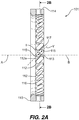
- Respective plane B shown in Fig. 2A , is associated with slot 112a and its respective injection axis I and is extending in and out of the plane of the paper in the orientation shown in Figs. 1-2A .
- the respective center injection axis I for slot 112a is parallel to, but off-set from, respective plane B, e.g. the respective injection axis I for slot 112a is also extending in and out of the plane of the paper in the orientation shown in Figs. 1-2A .
- Each slot 112 defines a respective longitudinal axis Y defined between points 115 on the inner diameter 116 of the annular body 110 between opposing slot ends.
- the slots 112 are tilted circumferentially so the longitudinal axes Y are angled with respect to the center axis A of the annular body 110.
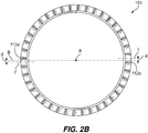
- annular body 110 As shown in Fig. 2B , an axial facing view of annular body 110 along center axis A is shown.
- the respective plane B bisecting the annular body 110 is shown to be parallel to two of the slot center axes, labeled I and I' for clarity.
- the bisecting plane B intersects both of the slots 112a and 112a' associated with injection axes I and I'.
- the respective center injection axes I for each of the slots 112 is perpendicular to the center axis A for the annular body 110.
- the slots 112 of air mixer 101 have little to no off-set, e.g. little to no tangential component to their injection direction. This is visible in Fig. 1 by comparing the distance d between injection axis I, associated with a respective slot 112a, and its respective parallel bisecting plane B, to the distance f between injection axis X, associated with a respective slot 109 of air swirler 108a, and its respective parallel bisecting plane B (the same as bisecting plane B parallel to injection axis I of slot 112a).
- an upstream side 113 of the slot 112a will have less off-set than a downstream side 117 of the slot 112a. It is this differential off-set across a given slot 112 that creates intra-mixing within the air stream for that slot. This tends to be important for mixing with any fuel which is injected into the air stream from fuel distributor 106c. Having a slight off-set causes intra-circuit churning which allows the innermost air from the air mixer 101, e.g. the air entering from the upstream side 113 of the slots 112, to mix with the outermost air of the air mixer 101, e.g. the air entering from the downstream sides 117 of the slots 112.
- the off-set direction can be opposite of the off-set direction of the inner air swirler 108b, resulting in a slight counter-swirl between the two air circuits, or it can be in the same direction as the swirl from inner air swirler 108b, resulting in slight co-swirling.
- upstream and downstream sides 113 and 117, respectively, are designated by the respective centers for the arcs forming the ends of the pill shaped slots 112 defined on the inner surface 116 of air mixer 101.
- an air mixer 201 includes an annular body 210 defining a center axis A.
- a plurality of slots 212 are defined in the annular body 210 circumferentially spaced apart from one another.
- Each slot 212 defines a respective center injection axis I extending from an outer surface 214 of the annular body 210 to an inner surface 216 of the annular body 210.
- Each respective center injection axis I is parallel to a respective plane B bisecting the annular body 210.
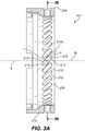
- Air mixer 201 is similar to air mixer 101 except that center injection axis I for a slot 212a is also defined within its respective bisecting plane B and intersects center axis A. For the respective plane B shown in Figs.
- the center injection axis I for slot 212a is parallel to respective plane B, e.g. the respective injection axis I for slot 212a is also extending in and out of the plane of the paper, as oriented in the view of Fig. 3A .
- the respective center injection axes I for each of the slots 212 is perpendicular to the center axis A for the annular body 210.
- Each slot 212 defines a respective longitudinal axis Y defined between points 215 on the inner surface of the annular body between opposing slot ends.
- the slots 212 are tilted circumferentially so the longitudinal axes Y are angled with respect to the center axis A of the annular body 210, similar to slots 112 described above.
- air mixer 201 can also be used in combustor system 100.
- slots 212 of air mixer 201 similarly have little to no off-set, e.g. little to no tangential component to their injection direction.
- a given one of slots 212 in the air mixer 201 also has a differential off-set across the slot.
- An upstream side 213 of the slot 212a will have an equal but opposite off-set to a downstream side 217 of the slot 212a.
- This differential off-set across a given slot 212 creates intra-mixing within the air stream similar to that described for slot 112. Having a slight off-set causes intra-circuit churning which allows the innermost air from the air mixer 201, e.g. the air entering from the upstream side 213 of the slots 212, to mix with the outermost air of the air mixer 201, e.g. the air entering from the downstream sides 217 of the slots 112.
- an air mixer 301 includes an annular body 310 defining a center axis A.
- a plurality of slots 312 are defined in the annular body 310 circumferentially spaced apart from one another.
- Each slot 312 defines a respective center injection axis I extending from an outer surface 314 of the annular body 310 to an inner surface 316 of the annular body 310.
- the respective center injection axes I for each of the slots 312 are at oblique angles relative to the center axis A of the annular body 310, meaning that a given center injection axis I for a respective slot 312 has a respective axial and radial component.
- each respective center injection axis I is parallel to a respective plane B bisecting the annular body 310.
- the center injection axis I for slot 312a is parallel to respective plane B, e.g. the respective injection axis I for slot 312a and bisecting plane B are extending in and out of the plane of the paper as oriented in Fig. 4 .
- axis I for slot 312b at the top of Fig. 4 .
- air mixer 301 can also be used in combustor system 100.
- slots 312 of air mixer 301 similarly have little to no off-set, e.g. little to no tangential component to their injection direction.
- a given one of slots 312 in air mixer 301 also has a differential off-set across the slot.
- An upstream side 313 of the slot 212a will have less off-set than a downstream side 317 of the slot 312a, similar to that described with respect to air mixer 101.
- This differential off-set across a given slot 312 creates intra-mixing within the air stream similar to that described for slot 112. Having a slight off-set causes intra-circuit churning which allows the innermost air from the air mixer 301, e.g. the air entering from the upstream side 313 of the slots 312, to mix with the outermost air of the air mixer 301, e.g. the air entering from the downstream sides 317 of the slots 312.
- air mixers 101, 201 and 301as described herein can be retrofitted into existing combustors and gas turbine engines.
- the methods and systems of the present disclosure as described above and shown in the drawings, provide for combustor systems with superior properties including better fuel-air mixing, resulting in more efficient burning and reduced emissions. While the apparatus and methods of the subject disclosure have been shown and described with reference to preferred embodiments, those skilled in the art will readily appreciate that changes and/or modifications may be made thereto without departing from the scope of the subject disclosure.
Landscapes
- Engineering & Computer Science (AREA)
- Chemical & Material Sciences (AREA)
- Combustion & Propulsion (AREA)
- Mechanical Engineering (AREA)
- General Engineering & Computer Science (AREA)
Abstract
Description
- The present disclosure relates to combustors, and more particularly to air mixers such as those used in combustor nozzles for gas turbine engines.
- In gas turbine engines, such as industrial gas turbine engines used for power production, injectors within the gas turbine engine mix air and fuel together for combustion. To reduce NOx emissions, air and fuel need to be adequately mixed. If the injector does not mix the fuel and air well, less than desirable emissions can result. Typically, fuel is atomized with air fed through air injectors proximate to the fuel injector lip.
- The conventional techniques have been considered satisfactory for their intended purpose. However, there is an ever present need for improved fuel injection and air-fuel mixing. This disclosure provides a solution for this.
- An air mixer includes an annular body defining a center axis. A plurality of slots are defined in the annular body circumferentially spaced apart from one another. Each slot defines a respective center injection axis extending from an outer surface of the annular body to an inner surface of the annular body. Each respective center injection axis is parallel to a respective plane bisecting the annular body. At least one of the slots is intersected by the respective bisecting plane parallel to its respective center injection axis.
- The respective plane bisecting the annular body can be parallel to two of the slot center axes. In accordance with some embodiments, the respective center injection axis for at least one of the plurality of slots is defined within its respective bisecting plane. Each slot can define a respective longitudinal axis defined between points on the inner surface of the annular body between opposing slot ends. At least one of the longitudinal axes can be angled with respect to the center axis of the annular body. At least one of the longitudinal axes can be angled with respect to the center axis of the annular body. At least one of the center injection axes can be perpendicular to the center axis of the annular body. At least one of the center injection axes can be at an oblique angle relative to the center axis of the annular body. A distance between an upstream side of a given one of the plurality of slots and its respective plane in a direction perpendicular to the respective plane can be different from a distance between a downstream side of the given slot and the respective plane in a direction perpendicular to the respective plane.
- In accordance with another aspect, a combustor system includes a combustor case and a manifold operatively connected to the combustor case. A fuel distributor is downstream from and fluidly connected to the manifold. An air swirler is upstream from the fuel distributor to impart swirl to air going from within the combustor case into a combustor. An air mixer is downstream from the fuel distributor. The air mixer is similar to the air mixer described above.
- These and other features of the systems and methods of the subject disclosure will become more readily apparent to those skilled in the art from the following detailed description of the preferred embodiments taken in conjunction with the drawings.
- So that those skilled in the art to which the subject disclosure appertains will readily understand how to make and use the devices and methods of the subject disclosure without undue experimentation, preferred embodiments thereof will be described in detail herein below with reference to certain figures, wherein:
-
Fig. 1 is a schematic cross-sectional side view of an exemplary embodiment of a combustor system having an embodiment of an air mixer constructed in accordance with the present disclosure, showing circumferentially spaced apart injection slots; -
Fig. 2A is a schematic cross-sectional side view of the air mixer ofFig. 1 , showing one of the injection slots with its respective injection axis; -
Fig. 2B is a schematic cross-sectional axial view of the air mixer ofFig. 1 , showing the respective injection axis off-set from and parallel to its respective bisecting plane; -
Fig. 3A is a schematic cross-sectional side view of another embodiment of an air mixer constructed in accordance with the present disclosure, showing one of the injection slots with its respective injection axis; -
Fig. 3B is a schematic cross-sectional axial view of the air mixer ofFig. 3A , showing the respective injection axis off-set from and parallel to its respective bisecting plane; and -
Fig. 4 is a schematic cross-sectional side view of another embodiment of an air mixer constructed in accordance with the present disclosure, wherein one of the injection slots and its respective injection axis are shown, where the injection axis is off-set from and parallel to its respective bisecting plane. - Reference will now be made to the drawings wherein like reference numerals identify similar structural features or aspects of the subject disclosure. For purposes of explanation and illustration, and not limitation, a partial view of an exemplary embodiment of a combustor system with an exemplary embodiment of an air mixer in accordance with the disclosure is shown in
Fig. 1 and is designated generally byreference character 100. Other embodiments of combustor systems in accordance with the disclosure, or aspects thereof, are provided inFigs. 2A-4 , as will be described. The systems and methods described herein can be used to distribute air and mix it with fluids, including gas or liquid fuel, such as in multiple stage, dual fuel injection for gas turbine engines. - As shown in
Fig. 1 , acombustor system 100 includes acombustor case 102 and amanifold 104 operatively connected to the combustor case. Stages offuel distributors 106a-c are downstream from and fluidly connected to themanifold 104. Thesystem 100 includes anignitor 105 seated in acentral passage 107 of themanifold 104 for ignition of fuel issued from thefuel distributors 106a-c.Air swirlers fuel distributors 106a-c to impart swirl to air going from within thecombustor case 102 into acombustor 103. The swirling air helps to atomize the fuel entering intocombustor 103 fromfuel distributors 106a-c and mixes with the fuel to create a fuel-air mixture. Anair mixer 101 downstream from the downstreammost fuel distributor 106c further mixes the fuel-air mixture. - With reference now to
Fig. 2A , theair mixer 101 includes anannular body 110 defining a center axis A. A plurality ofslots 112 are defined in theannular body 110 circumferentially spaced apart from one another. Eachslot 112 defines a respective center injection axis I extending from anouter surface 114 of theannular body 110 to aninner surface 116 of theannular body 110. Each respective center injection axis I is parallel to a respective plane B that bisects theannular body 110. Respective plane B, shown inFig. 2A , is associated withslot 112a and its respective injection axis I and is extending in and out of the plane of the paper in the orientation shown inFigs. 1-2A . The respective center injection axis I forslot 112a is parallel to, but off-set from, respective plane B, e.g. the respective injection axis I forslot 112a is also extending in and out of the plane of the paper in the orientation shown inFigs. 1-2A . Eachslot 112 defines a respective longitudinal axis Y defined betweenpoints 115 on theinner diameter 116 of theannular body 110 between opposing slot ends. Theslots 112 are tilted circumferentially so the longitudinal axes Y are angled with respect to the center axis A of theannular body 110. - As shown in
Fig. 2B , an axial facing view ofannular body 110 along center axis A is shown. In this view, the respective plane B bisecting theannular body 110 is shown to be parallel to two of the slot center axes, labeled I and I' for clarity. The bisecting plane B intersects both of theslots slots 112 is perpendicular to the center axis A for theannular body 110. - With reference now to
Figs. 1-2B , unlikeair swirlers 108a-c, theslots 112 ofair mixer 101 have little to no off-set, e.g. little to no tangential component to their injection direction. This is visible inFig. 1 by comparing the distance d between injection axis I, associated with arespective slot 112a, and its respective parallel bisecting plane B, to the distance f between injection axis X, associated with arespective slot 109 ofair swirler 108a, and its respective parallel bisecting plane B (the same as bisecting plane B parallel to injection axis I ofslot 112a). Even with the slight off-set forair mixer 101, anupstream side 113 of theslot 112a will have less off-set than adownstream side 117 of theslot 112a. It is this differential off-set across a givenslot 112 that creates intra-mixing within the air stream for that slot. This tends to be important for mixing with any fuel which is injected into the air stream fromfuel distributor 106c. Having a slight off-set causes intra-circuit churning which allows the innermost air from theair mixer 101, e.g. the air entering from theupstream side 113 of theslots 112, to mix with the outermost air of theair mixer 101, e.g. the air entering from thedownstream sides 117 of theslots 112. The off-set direction can be opposite of the off-set direction of theinner air swirler 108b, resulting in a slight counter-swirl between the two air circuits, or it can be in the same direction as the swirl frominner air swirler 108b, resulting in slight co-swirling. For ease of explanation, upstream anddownstream sides slots 112 defined on theinner surface 116 ofair mixer 101. - In the embodiment of
Fig. 3A-3B , anair mixer 201 includes anannular body 210 defining a center axis A. A plurality ofslots 212 are defined in theannular body 210 circumferentially spaced apart from one another. Eachslot 212 defines a respective center injection axis I extending from anouter surface 214 of theannular body 210 to aninner surface 216 of theannular body 210. Each respective center injection axis I is parallel to a respective plane B bisecting theannular body 210.Air mixer 201 is similar toair mixer 101 except that center injection axis I for aslot 212a is also defined within its respective bisecting plane B and intersects center axis A. For the respective plane B shown inFigs. 3A-3B , which would be extending in and out of the plane of the paper as oriented in the views ofFigs. 3A-3B , the center injection axis I forslot 212a is parallel to respective plane B, e.g. the respective injection axis I forslot 212a is also extending in and out of the plane of the paper, as oriented in the view ofFig. 3A . The respective center injection axes I for each of theslots 212 is perpendicular to the center axis A for theannular body 210. Eachslot 212 defines a respective longitudinal axis Y defined betweenpoints 215 on the inner surface of the annular body between opposing slot ends. Theslots 212 are tilted circumferentially so the longitudinal axes Y are angled with respect to the center axis A of theannular body 210, similar toslots 112 described above. Those skilled in the art will readily appreciate thatair mixer 201 can also be used incombustor system 100. - With continued reference to
Figs. 3A and3B ,slots 212 ofair mixer 201 similarly have little to no off-set, e.g. little to no tangential component to their injection direction. A given one ofslots 212 in theair mixer 201 also has a differential off-set across the slot. Anupstream side 213 of theslot 212a will have an equal but opposite off-set to adownstream side 217 of theslot 212a. This differential off-set across a givenslot 212 creates intra-mixing within the air stream similar to that described forslot 112. Having a slight off-set causes intra-circuit churning which allows the innermost air from theair mixer 201, e.g. the air entering from theupstream side 213 of theslots 212, to mix with the outermost air of theair mixer 201, e.g. the air entering from thedownstream sides 217 of theslots 112. - In the embodiment of
Fig. 4 , anair mixer 301 includes anannular body 310 defining a center axis A. A plurality ofslots 312 are defined in theannular body 310 circumferentially spaced apart from one another. Eachslot 312 defines a respective center injection axis I extending from anouter surface 314 of theannular body 310 to aninner surface 316 of theannular body 310. Contrary to the embodiments ofFigs. 1-3B , described above, the respective center injection axes I for each of theslots 312 are at oblique angles relative to the center axis A of theannular body 310, meaning that a given center injection axis I for arespective slot 312 has a respective axial and radial component. This is evident by the injection axis I shown for theslot 312 depicted on the top side of theair mixer 301 as oriented inFig. 4 . Otherwise, the embodiment ofFig. 4 is substantially similar to those ofFigs. 1-3B . Each respective center injection axis I is parallel to a respective plane B bisecting theannular body 310. For the respective plane B associated withslot 312a, the center injection axis I forslot 312a is parallel to respective plane B, e.g. the respective injection axis I forslot 312a and bisecting plane B are extending in and out of the plane of the paper as oriented inFig. 4 . This can be seen with axis I forslot 312b at the top ofFig. 4 . Those skilled in the art will readily appreciate thatair mixer 301 can also be used incombustor system 100. - With continued reference to
Fig. 4 ,slots 312 ofair mixer 301 similarly have little to no off-set, e.g. little to no tangential component to their injection direction. A given one ofslots 312 inair mixer 301 also has a differential off-set across the slot. Anupstream side 313 of theslot 212a will have less off-set than adownstream side 317 of theslot 312a, similar to that described with respect toair mixer 101. This differential off-set across a givenslot 312 creates intra-mixing within the air stream similar to that described forslot 112. Having a slight off-set causes intra-circuit churning which allows the innermost air from theair mixer 301, e.g. the air entering from theupstream side 313 of theslots 312, to mix with the outermost air of theair mixer 301, e.g. the air entering from thedownstream sides 317 of theslots 312. - It is contemplated that
air mixers
Claims (15)
- An air mixer comprising:an annular body defining a center axis; anda plurality of slots defined in the annular body circumferentially spaced apart from one another, wherein each slot defines a respective center injection axis extending from an outer surface of the annular body to an inner surface of the annular body, wherein each respective center injection axis is parallel to a respective plane bisecting the annular body, wherein at least one of the slots is intersected by the respective bisecting plane parallel to its respective center injection axis.
- The air mixer as recited in Claim 1, wherein the respective plane bisecting the annular body is parallel to two of the slot center injection axes.
- The air mixer as recited in Claim 1 or 2, wherein the respective center injection axis for at least one of the plurality of slots is defined within its respective bisecting plane.
- The air mixer as recited in Claim 1, 2 or 3, wherein each slot defines a respective longitudinal axis defined between points on the inner surface of the annular body between opposing slot ends.
- The air mixer as recited in Claim 4, wherein at least one of the longitudinal axes is angled with respect to the center axis of the annular body.
- The air mixer as recited in any preceding Claim, wherein at least one of the center injection axes is perpendicular to the center axis of the annular body.
- The air mixer as recited in any of Claims 1 to 5, wherein at least one of the center injection axes is at an oblique angle relative to the center axis of the annular body.
- The air mixer as recited in any preceding Claim, wherein a distance between an upstream side of a given one of the plurality of slots and its respective plane in a direction perpendicular to the respective plane is different from a distance between a downstream side of the given slot and the respective plane in a direction perpendicular to the respective plane.
- A combustor system comprising:a combustor case;a manifold operatively connected to the combustor case;a fuel distributor downstream from and fluidly connected to the manifold;an air swirler upstream from the fuel distributor to impart swirl to air going from within the combustor case into a combustor; andan air mixer downstream from the fuel distributor, wherein the air mixer includes:an annular body defining a center axis; anda plurality of slots defined in the annular body circumferentially spaced apart from one another, wherein each slot defines a respective center injection axis extending from an outer surface of the annular body to an inner surface of the annular body, wherein each respective center injection axis is parallel to a respective plane bisecting the annular body, wherein at least one of the slots is intersected by the respective bisecting plane parallel to its respective center injection axis.
- The combustor system as recited in Claim 9, wherein the respective plane bisecting the annular body is parallel to two of the slot center injection axes.
- The combustor system as recited in Claim 9 or 10, wherein the respective center injection axis for at least one of the plurality of slots is defined within its respective bisecting plane.
- The combustor system as recited in Claim 9, 10 or 11, wherein each slot defines a respective longitudinal axis defined between points on the inner surface of the annular body between opposing slot ends.
- The combustor system as recited in Claim 12, wherein at least one of the longitudinal axes is angled with respect to the center axis of the annular body.
- The combustor system as recited in any of Claims 9 to 13, wherein at least one of the center injection axes is perpendicular to the center axis of the annular body, or
wherein at least one of the center injection axes is at an oblique angle relative to the center axis of the annular body. - The combustor system as recited in any of Claims 9 to 14, wherein a distance between an upstream side of a given one of the plurality of slots and its respective plane in a direction perpendicular to the respective plane is different from a distance between a downstream side of the given slot and the respective plane in a direction perpendicular to the respective plane.
Applications Claiming Priority (1)
| Application Number | Priority Date | Filing Date | Title |
|---|---|---|---|
| US15/716,295 US11131459B2 (en) | 2017-09-26 | 2017-09-26 | Combustor with an air mixer and an air swirler each having slots |
Publications (2)
| Publication Number | Publication Date |
|---|---|
| EP3460333A1 true EP3460333A1 (en) | 2019-03-27 |
| EP3460333B1 EP3460333B1 (en) | 2024-02-07 |
Family
ID=63683702
Family Applications (1)
| Application Number | Title | Priority Date | Filing Date |
|---|---|---|---|
| EP18196473.5A Active EP3460333B1 (en) | 2017-09-26 | 2018-09-25 | Combustor system |
Country Status (2)
| Country | Link |
|---|---|
| US (2) | US11131459B2 (en) |
| EP (1) | EP3460333B1 (en) |
Citations (5)
| Publication number | Priority date | Publication date | Assignee | Title |
|---|---|---|---|---|
| EP1605204A2 (en) * | 2004-06-09 | 2005-12-14 | Delavan Inc | Conical swirler for fuel injectors and combustor domes and methods of manufacturing the same |
| US20140245742A1 (en) * | 2013-03-04 | 2014-09-04 | Delavan Inc | Air swirlers |
| EP3048372A1 (en) * | 2015-01-26 | 2016-07-27 | Delavan, Inc. | Flexible swirlers |
| US20170102147A1 (en) * | 2015-10-09 | 2017-04-13 | General Electric Company | Fuel-air premixer for a gas turbine |
| EP3309458A1 (en) * | 2016-10-13 | 2018-04-18 | Rolls-Royce plc | A combustion chamber and a combustion chamber fuel injector seal |
Family Cites Families (9)
| Publication number | Priority date | Publication date | Assignee | Title |
|---|---|---|---|---|
| US4271675A (en) * | 1977-10-21 | 1981-06-09 | Rolls-Royce Limited | Combustion apparatus for gas turbine engines |
| US4301657A (en) * | 1978-05-04 | 1981-11-24 | Caterpillar Tractor Co. | Gas turbine combustion chamber |
| US4903478A (en) * | 1987-06-25 | 1990-02-27 | General Electric Company | Dual manifold fuel system |
| US7565803B2 (en) * | 2005-07-25 | 2009-07-28 | General Electric Company | Swirler arrangement for mixer assembly of a gas turbine engine combustor having shaped passages |
| US8161751B2 (en) * | 2009-04-30 | 2012-04-24 | General Electric Company | High volume fuel nozzles for a turbine engine |
| US9188063B2 (en) * | 2011-11-03 | 2015-11-17 | Delavan Inc. | Injectors for multipoint injection |
| US10344981B2 (en) * | 2016-12-16 | 2019-07-09 | Delavan Inc. | Staged dual fuel radial nozzle with radial liquid fuel distributor |
| CN108731029B (en) * | 2017-04-25 | 2021-10-29 | 帕克-汉尼芬公司 | Jet fuel nozzle |
| US11002193B2 (en) * | 2017-12-15 | 2021-05-11 | Delavan Inc. | Fuel injector systems and support structures |
-
2017
- 2017-09-26 US US15/716,295 patent/US11131459B2/en active Active
-
2018
- 2018-09-25 EP EP18196473.5A patent/EP3460333B1/en active Active
-
2021
- 2021-08-26 US US17/458,240 patent/US11674689B2/en active Active
Patent Citations (5)
| Publication number | Priority date | Publication date | Assignee | Title |
|---|---|---|---|---|
| EP1605204A2 (en) * | 2004-06-09 | 2005-12-14 | Delavan Inc | Conical swirler for fuel injectors and combustor domes and methods of manufacturing the same |
| US20140245742A1 (en) * | 2013-03-04 | 2014-09-04 | Delavan Inc | Air swirlers |
| EP3048372A1 (en) * | 2015-01-26 | 2016-07-27 | Delavan, Inc. | Flexible swirlers |
| US20170102147A1 (en) * | 2015-10-09 | 2017-04-13 | General Electric Company | Fuel-air premixer for a gas turbine |
| EP3309458A1 (en) * | 2016-10-13 | 2018-04-18 | Rolls-Royce plc | A combustion chamber and a combustion chamber fuel injector seal |
Also Published As
| Publication number | Publication date |
|---|---|
| EP3460333B1 (en) | 2024-02-07 |
| US11131459B2 (en) | 2021-09-28 |
| US20210404661A1 (en) | 2021-12-30 |
| US11674689B2 (en) | 2023-06-13 |
| US20190093894A1 (en) | 2019-03-28 |
Similar Documents
| Publication | Publication Date | Title |
|---|---|---|
| EP4050262B1 (en) | Fuel injectors for use in a gas turbine combustor | |
| US10851999B2 (en) | Fuel injectors and methods of use in gas turbine combustor | |
| US6363726B1 (en) | Mixer having multiple swirlers | |
| US11371708B2 (en) | Premixer for low emissions gas turbine combustor | |
| US6092363A (en) | Low Nox combustor having dual fuel injection system | |
| US9752781B2 (en) | Flamesheet combustor dome | |
| US7757491B2 (en) | Fuel nozzle for a gas turbine engine and method for fabricating the same | |
| KR102290152B1 (en) | Air fuel premixer for low emissions gas turbine combustor | |
| EP3450849A1 (en) | Premixing fuel injectors and methods of use in gas turbine combustor | |
| EP3336433B1 (en) | Staged dual fuel radial nozzle with radial liquid fuel distributor | |
| US11846425B2 (en) | Dual fuel gas turbine engine pilot nozzles | |
| JP6297165B2 (en) | Gas turbine engine having two outlet fuel premix nozzles for a secondary fuel stage | |
| CN103307631A (en) | System for enhancing mixing in a multi-tube fuel nozzle | |
| US20190101291A1 (en) | Air swirlers | |
| US11649963B2 (en) | Liquid fuel injector | |
| EP2340398B1 (en) | Alternately swirling mains in lean premixed gas turbine combustors | |
| US11674689B2 (en) | Combustor with an air mixer and an air swirler each having slots | |
| EP2584267B1 (en) | Injector having multiple fuel pegs | |
| JP2003194337A (en) | Gas turbine combustor premixing equipment | |
| JP2005090884A (en) | Fuel injection valve for gas turbine and low NOx combustor |
Legal Events
| Date | Code | Title | Description |
|---|---|---|---|
| PUAI | Public reference made under article 153(3) epc to a published international application that has entered the european phase |
Free format text: ORIGINAL CODE: 0009012 |
|
| STAA | Information on the status of an ep patent application or granted ep patent |
Free format text: STATUS: THE APPLICATION HAS BEEN PUBLISHED |
|
| AK | Designated contracting states |
Kind code of ref document: A1 Designated state(s): AL AT BE BG CH CY CZ DE DK EE ES FI FR GB GR HR HU IE IS IT LI LT LU LV MC MK MT NL NO PL PT RO RS SE SI SK SM TR |
|
| AX | Request for extension of the european patent |
Extension state: BA ME |
|
| STAA | Information on the status of an ep patent application or granted ep patent |
Free format text: STATUS: REQUEST FOR EXAMINATION WAS MADE |
|
| 17P | Request for examination filed |
Effective date: 20190927 |
|
| RBV | Designated contracting states (corrected) |
Designated state(s): AL AT BE BG CH CY CZ DE DK EE ES FI FR GB GR HR HU IE IS IT LI LT LU LV MC MK MT NL NO PL PT RO RS SE SI SK SM TR |
|
| STAA | Information on the status of an ep patent application or granted ep patent |
Free format text: STATUS: EXAMINATION IS IN PROGRESS |
|
| 17Q | First examination report despatched |
Effective date: 20201015 |
|
| RAP3 | Party data changed (applicant data changed or rights of an application transferred) |
Owner name: COLLINS ENGINE NOZZLES, INC. |
|
| GRAP | Despatch of communication of intention to grant a patent |
Free format text: ORIGINAL CODE: EPIDOSNIGR1 |
|
| STAA | Information on the status of an ep patent application or granted ep patent |
Free format text: STATUS: GRANT OF PATENT IS INTENDED |
|
| INTG | Intention to grant announced |
Effective date: 20230323 |
|
| GRAJ | Information related to disapproval of communication of intention to grant by the applicant or resumption of examination proceedings by the epo deleted |
Free format text: ORIGINAL CODE: EPIDOSDIGR1 |
|
| STAA | Information on the status of an ep patent application or granted ep patent |
Free format text: STATUS: EXAMINATION IS IN PROGRESS |
|
| GRAP | Despatch of communication of intention to grant a patent |
Free format text: ORIGINAL CODE: EPIDOSNIGR1 |
|
| STAA | Information on the status of an ep patent application or granted ep patent |
Free format text: STATUS: GRANT OF PATENT IS INTENDED |
|
| INTC | Intention to grant announced (deleted) | ||
| INTG | Intention to grant announced |
Effective date: 20230816 |
|
| P01 | Opt-out of the competence of the unified patent court (upc) registered |
Effective date: 20230922 |
|
| GRAS | Grant fee paid |
Free format text: ORIGINAL CODE: EPIDOSNIGR3 |
|
| GRAA | (expected) grant |
Free format text: ORIGINAL CODE: 0009210 |
|
| STAA | Information on the status of an ep patent application or granted ep patent |
Free format text: STATUS: THE PATENT HAS BEEN GRANTED |
|
| AK | Designated contracting states |
Kind code of ref document: B1 Designated state(s): AL AT BE BG CH CY CZ DE DK EE ES FI FR GB GR HR HU IE IS IT LI LT LU LV MC MK MT NL NO PL PT RO RS SE SI SK SM TR |
|
| REG | Reference to a national code |
Ref country code: GB Ref legal event code: FG4D |
|
| REG | Reference to a national code |
Ref country code: CH Ref legal event code: EP |
|
| REG | Reference to a national code |
Ref country code: DE Ref legal event code: R096 Ref document number: 602018064897 Country of ref document: DE |
|
| REG | Reference to a national code |
Ref country code: IE Ref legal event code: FG4D |
|
| REG | Reference to a national code |
Ref country code: LT Ref legal event code: MG9D |
|
| REG | Reference to a national code |
Ref country code: NL Ref legal event code: MP Effective date: 20240207 |
|
| PG25 | Lapsed in a contracting state [announced via postgrant information from national office to epo] |
Ref country code: IS Free format text: LAPSE BECAUSE OF FAILURE TO SUBMIT A TRANSLATION OF THE DESCRIPTION OR TO PAY THE FEE WITHIN THE PRESCRIBED TIME-LIMIT Effective date: 20240607 |
|
| PG25 | Lapsed in a contracting state [announced via postgrant information from national office to epo] |
Ref country code: LT Free format text: LAPSE BECAUSE OF FAILURE TO SUBMIT A TRANSLATION OF THE DESCRIPTION OR TO PAY THE FEE WITHIN THE PRESCRIBED TIME-LIMIT Effective date: 20240207 |
|
| PG25 | Lapsed in a contracting state [announced via postgrant information from national office to epo] |
Ref country code: GR Free format text: LAPSE BECAUSE OF FAILURE TO SUBMIT A TRANSLATION OF THE DESCRIPTION OR TO PAY THE FEE WITHIN THE PRESCRIBED TIME-LIMIT Effective date: 20240508 |
|
| REG | Reference to a national code |
Ref country code: AT Ref legal event code: MK05 Ref document number: 1655598 Country of ref document: AT Kind code of ref document: T Effective date: 20240207 |
|
| PG25 | Lapsed in a contracting state [announced via postgrant information from national office to epo] |
Ref country code: HR Free format text: LAPSE BECAUSE OF FAILURE TO SUBMIT A TRANSLATION OF THE DESCRIPTION OR TO PAY THE FEE WITHIN THE PRESCRIBED TIME-LIMIT Effective date: 20240207 Ref country code: RS Free format text: LAPSE BECAUSE OF FAILURE TO SUBMIT A TRANSLATION OF THE DESCRIPTION OR TO PAY THE FEE WITHIN THE PRESCRIBED TIME-LIMIT Effective date: 20240507 Ref country code: NL Free format text: LAPSE BECAUSE OF FAILURE TO SUBMIT A TRANSLATION OF THE DESCRIPTION OR TO PAY THE FEE WITHIN THE PRESCRIBED TIME-LIMIT Effective date: 20240207 |
|
| PG25 | Lapsed in a contracting state [announced via postgrant information from national office to epo] |
Ref country code: ES Free format text: LAPSE BECAUSE OF FAILURE TO SUBMIT A TRANSLATION OF THE DESCRIPTION OR TO PAY THE FEE WITHIN THE PRESCRIBED TIME-LIMIT Effective date: 20240207 |
|
| PG25 | Lapsed in a contracting state [announced via postgrant information from national office to epo] |
Ref country code: AT Free format text: LAPSE BECAUSE OF FAILURE TO SUBMIT A TRANSLATION OF THE DESCRIPTION OR TO PAY THE FEE WITHIN THE PRESCRIBED TIME-LIMIT Effective date: 20240207 |
|
| PG25 | Lapsed in a contracting state [announced via postgrant information from national office to epo] |
Ref country code: RS Free format text: LAPSE BECAUSE OF FAILURE TO SUBMIT A TRANSLATION OF THE DESCRIPTION OR TO PAY THE FEE WITHIN THE PRESCRIBED TIME-LIMIT Effective date: 20240507 Ref country code: NO Free format text: LAPSE BECAUSE OF FAILURE TO SUBMIT A TRANSLATION OF THE DESCRIPTION OR TO PAY THE FEE WITHIN THE PRESCRIBED TIME-LIMIT Effective date: 20240507 Ref country code: NL Free format text: LAPSE BECAUSE OF FAILURE TO SUBMIT A TRANSLATION OF THE DESCRIPTION OR TO PAY THE FEE WITHIN THE PRESCRIBED TIME-LIMIT Effective date: 20240207 Ref country code: LT Free format text: LAPSE BECAUSE OF FAILURE TO SUBMIT A TRANSLATION OF THE DESCRIPTION OR TO PAY THE FEE WITHIN THE PRESCRIBED TIME-LIMIT Effective date: 20240207 Ref country code: IS Free format text: LAPSE BECAUSE OF FAILURE TO SUBMIT A TRANSLATION OF THE DESCRIPTION OR TO PAY THE FEE WITHIN THE PRESCRIBED TIME-LIMIT Effective date: 20240607 Ref country code: HR Free format text: LAPSE BECAUSE OF FAILURE TO SUBMIT A TRANSLATION OF THE DESCRIPTION OR TO PAY THE FEE WITHIN THE PRESCRIBED TIME-LIMIT Effective date: 20240207 Ref country code: GR Free format text: LAPSE BECAUSE OF FAILURE TO SUBMIT A TRANSLATION OF THE DESCRIPTION OR TO PAY THE FEE WITHIN THE PRESCRIBED TIME-LIMIT Effective date: 20240508 Ref country code: FI Free format text: LAPSE BECAUSE OF FAILURE TO SUBMIT A TRANSLATION OF THE DESCRIPTION OR TO PAY THE FEE WITHIN THE PRESCRIBED TIME-LIMIT Effective date: 20240207 Ref country code: ES Free format text: LAPSE BECAUSE OF FAILURE TO SUBMIT A TRANSLATION OF THE DESCRIPTION OR TO PAY THE FEE WITHIN THE PRESCRIBED TIME-LIMIT Effective date: 20240207 Ref country code: BG Free format text: LAPSE BECAUSE OF FAILURE TO SUBMIT A TRANSLATION OF THE DESCRIPTION OR TO PAY THE FEE WITHIN THE PRESCRIBED TIME-LIMIT Effective date: 20240207 Ref country code: AT Free format text: LAPSE BECAUSE OF FAILURE TO SUBMIT A TRANSLATION OF THE DESCRIPTION OR TO PAY THE FEE WITHIN THE PRESCRIBED TIME-LIMIT Effective date: 20240207 |
|
| PG25 | Lapsed in a contracting state [announced via postgrant information from national office to epo] |
Ref country code: PT Free format text: LAPSE BECAUSE OF FAILURE TO SUBMIT A TRANSLATION OF THE DESCRIPTION OR TO PAY THE FEE WITHIN THE PRESCRIBED TIME-LIMIT Effective date: 20240607 Ref country code: PL Free format text: LAPSE BECAUSE OF FAILURE TO SUBMIT A TRANSLATION OF THE DESCRIPTION OR TO PAY THE FEE WITHIN THE PRESCRIBED TIME-LIMIT Effective date: 20240207 |
|
| PG25 | Lapsed in a contracting state [announced via postgrant information from national office to epo] |
Ref country code: SE Free format text: LAPSE BECAUSE OF FAILURE TO SUBMIT A TRANSLATION OF THE DESCRIPTION OR TO PAY THE FEE WITHIN THE PRESCRIBED TIME-LIMIT Effective date: 20240207 Ref country code: PT Free format text: LAPSE BECAUSE OF FAILURE TO SUBMIT A TRANSLATION OF THE DESCRIPTION OR TO PAY THE FEE WITHIN THE PRESCRIBED TIME-LIMIT Effective date: 20240607 Ref country code: PL Free format text: LAPSE BECAUSE OF FAILURE TO SUBMIT A TRANSLATION OF THE DESCRIPTION OR TO PAY THE FEE WITHIN THE PRESCRIBED TIME-LIMIT Effective date: 20240207 Ref country code: LV Free format text: LAPSE BECAUSE OF FAILURE TO SUBMIT A TRANSLATION OF THE DESCRIPTION OR TO PAY THE FEE WITHIN THE PRESCRIBED TIME-LIMIT Effective date: 20240207 |
|
| PG25 | Lapsed in a contracting state [announced via postgrant information from national office to epo] |
Ref country code: DK Free format text: LAPSE BECAUSE OF FAILURE TO SUBMIT A TRANSLATION OF THE DESCRIPTION OR TO PAY THE FEE WITHIN THE PRESCRIBED TIME-LIMIT Effective date: 20240207 |
|
| PG25 | Lapsed in a contracting state [announced via postgrant information from national office to epo] |
Ref country code: SM Free format text: LAPSE BECAUSE OF FAILURE TO SUBMIT A TRANSLATION OF THE DESCRIPTION OR TO PAY THE FEE WITHIN THE PRESCRIBED TIME-LIMIT Effective date: 20240207 |
|
| PG25 | Lapsed in a contracting state [announced via postgrant information from national office to epo] |
Ref country code: CZ Free format text: LAPSE BECAUSE OF FAILURE TO SUBMIT A TRANSLATION OF THE DESCRIPTION OR TO PAY THE FEE WITHIN THE PRESCRIBED TIME-LIMIT Effective date: 20240207 Ref country code: EE Free format text: LAPSE BECAUSE OF FAILURE TO SUBMIT A TRANSLATION OF THE DESCRIPTION OR TO PAY THE FEE WITHIN THE PRESCRIBED TIME-LIMIT Effective date: 20240207 |
|
| PG25 | Lapsed in a contracting state [announced via postgrant information from national office to epo] |
Ref country code: SK Free format text: LAPSE BECAUSE OF FAILURE TO SUBMIT A TRANSLATION OF THE DESCRIPTION OR TO PAY THE FEE WITHIN THE PRESCRIBED TIME-LIMIT Effective date: 20240207 |
|
| PG25 | Lapsed in a contracting state [announced via postgrant information from national office to epo] |
Ref country code: SM Free format text: LAPSE BECAUSE OF FAILURE TO SUBMIT A TRANSLATION OF THE DESCRIPTION OR TO PAY THE FEE WITHIN THE PRESCRIBED TIME-LIMIT Effective date: 20240207 Ref country code: SK Free format text: LAPSE BECAUSE OF FAILURE TO SUBMIT A TRANSLATION OF THE DESCRIPTION OR TO PAY THE FEE WITHIN THE PRESCRIBED TIME-LIMIT Effective date: 20240207 Ref country code: RO Free format text: LAPSE BECAUSE OF FAILURE TO SUBMIT A TRANSLATION OF THE DESCRIPTION OR TO PAY THE FEE WITHIN THE PRESCRIBED TIME-LIMIT Effective date: 20240207 Ref country code: EE Free format text: LAPSE BECAUSE OF FAILURE TO SUBMIT A TRANSLATION OF THE DESCRIPTION OR TO PAY THE FEE WITHIN THE PRESCRIBED TIME-LIMIT Effective date: 20240207 Ref country code: DK Free format text: LAPSE BECAUSE OF FAILURE TO SUBMIT A TRANSLATION OF THE DESCRIPTION OR TO PAY THE FEE WITHIN THE PRESCRIBED TIME-LIMIT Effective date: 20240207 Ref country code: CZ Free format text: LAPSE BECAUSE OF FAILURE TO SUBMIT A TRANSLATION OF THE DESCRIPTION OR TO PAY THE FEE WITHIN THE PRESCRIBED TIME-LIMIT Effective date: 20240207 |
|
| REG | Reference to a national code |
Ref country code: DE Ref legal event code: R097 Ref document number: 602018064897 Country of ref document: DE |
|
| PG25 | Lapsed in a contracting state [announced via postgrant information from national office to epo] |
Ref country code: IT Free format text: LAPSE BECAUSE OF FAILURE TO SUBMIT A TRANSLATION OF THE DESCRIPTION OR TO PAY THE FEE WITHIN THE PRESCRIBED TIME-LIMIT Effective date: 20240207 |
|
| PLBE | No opposition filed within time limit |
Free format text: ORIGINAL CODE: 0009261 |
|
| STAA | Information on the status of an ep patent application or granted ep patent |
Free format text: STATUS: NO OPPOSITION FILED WITHIN TIME LIMIT |
|
| PG25 | Lapsed in a contracting state [announced via postgrant information from national office to epo] |
Ref country code: IT Free format text: LAPSE BECAUSE OF FAILURE TO SUBMIT A TRANSLATION OF THE DESCRIPTION OR TO PAY THE FEE WITHIN THE PRESCRIBED TIME-LIMIT Effective date: 20240207 |
|
| 26N | No opposition filed |
Effective date: 20241108 |
|
| PG25 | Lapsed in a contracting state [announced via postgrant information from national office to epo] |
Ref country code: SI Free format text: LAPSE BECAUSE OF FAILURE TO SUBMIT A TRANSLATION OF THE DESCRIPTION OR TO PAY THE FEE WITHIN THE PRESCRIBED TIME-LIMIT Effective date: 20240207 Ref country code: MC Free format text: LAPSE BECAUSE OF FAILURE TO SUBMIT A TRANSLATION OF THE DESCRIPTION OR TO PAY THE FEE WITHIN THE PRESCRIBED TIME-LIMIT Effective date: 20240207 |
|
| REG | Reference to a national code |
Ref country code: CH Ref legal event code: PL |
|
| PG25 | Lapsed in a contracting state [announced via postgrant information from national office to epo] |
Ref country code: LU Free format text: LAPSE BECAUSE OF NON-PAYMENT OF DUE FEES Effective date: 20240925 |
|
| REG | Reference to a national code |
Ref country code: BE Ref legal event code: MM Effective date: 20240930 |
|
| PG25 | Lapsed in a contracting state [announced via postgrant information from national office to epo] |
Ref country code: BE Free format text: LAPSE BECAUSE OF NON-PAYMENT OF DUE FEES Effective date: 20240930 |
|
| PG25 | Lapsed in a contracting state [announced via postgrant information from national office to epo] |
Ref country code: CH Free format text: LAPSE BECAUSE OF NON-PAYMENT OF DUE FEES Effective date: 20240930 |
|
| PG25 | Lapsed in a contracting state [announced via postgrant information from national office to epo] |
Ref country code: IE Free format text: LAPSE BECAUSE OF NON-PAYMENT OF DUE FEES Effective date: 20240925 |
|
| PGFP | Annual fee paid to national office [announced via postgrant information from national office to epo] |
Ref country code: DE Payment date: 20250820 Year of fee payment: 8 |
|
| PGFP | Annual fee paid to national office [announced via postgrant information from national office to epo] |
Ref country code: GB Payment date: 20250822 Year of fee payment: 8 |
|
| PGFP | Annual fee paid to national office [announced via postgrant information from national office to epo] |
Ref country code: FR Payment date: 20250820 Year of fee payment: 8 |
|
| PG25 | Lapsed in a contracting state [announced via postgrant information from national office to epo] |
Ref country code: CY Free format text: LAPSE BECAUSE OF FAILURE TO SUBMIT A TRANSLATION OF THE DESCRIPTION OR TO PAY THE FEE WITHIN THE PRESCRIBED TIME-LIMIT; INVALID AB INITIO Effective date: 20180925 |
|
| PG25 | Lapsed in a contracting state [announced via postgrant information from national office to epo] |
Ref country code: HU Free format text: LAPSE BECAUSE OF FAILURE TO SUBMIT A TRANSLATION OF THE DESCRIPTION OR TO PAY THE FEE WITHIN THE PRESCRIBED TIME-LIMIT; INVALID AB INITIO Effective date: 20180925 |
|
| PG25 | Lapsed in a contracting state [announced via postgrant information from national office to epo] |
Ref country code: TR Free format text: LAPSE BECAUSE OF FAILURE TO SUBMIT A TRANSLATION OF THE DESCRIPTION OR TO PAY THE FEE WITHIN THE PRESCRIBED TIME-LIMIT Effective date: 20240207 |