EP3460269A1 - Fluid film bearing for a wind turbine - Google Patents
Fluid film bearing for a wind turbine Download PDFInfo
- Publication number
- EP3460269A1 EP3460269A1 EP17192112.5A EP17192112A EP3460269A1 EP 3460269 A1 EP3460269 A1 EP 3460269A1 EP 17192112 A EP17192112 A EP 17192112A EP 3460269 A1 EP3460269 A1 EP 3460269A1
- Authority
- EP
- European Patent Office
- Prior art keywords
- bearing
- fluid
- elastomer
- pad
- supporting structure
- Prior art date
- Legal status (The legal status is an assumption and is not a legal conclusion. Google has not performed a legal analysis and makes no representation as to the accuracy of the status listed.)
- Withdrawn
Links
Images

Classifications
-
- F—MECHANICAL ENGINEERING; LIGHTING; HEATING; WEAPONS; BLASTING
- F16—ENGINEERING ELEMENTS AND UNITS; GENERAL MEASURES FOR PRODUCING AND MAINTAINING EFFECTIVE FUNCTIONING OF MACHINES OR INSTALLATIONS; THERMAL INSULATION IN GENERAL
- F16C—SHAFTS; FLEXIBLE SHAFTS; ELEMENTS OR CRANKSHAFT MECHANISMS; ROTARY BODIES OTHER THAN GEARING ELEMENTS; BEARINGS
- F16C17/00—Sliding-contact bearings for exclusively rotary movement
- F16C17/02—Sliding-contact bearings for exclusively rotary movement for radial load only
- F16C17/03—Sliding-contact bearings for exclusively rotary movement for radial load only with tiltably-supported segments, e.g. Michell bearings
- F16C17/035—Sliding-contact bearings for exclusively rotary movement for radial load only with tiltably-supported segments, e.g. Michell bearings the segments being integrally formed with, or rigidly fixed to, a support-element
-
- F—MECHANICAL ENGINEERING; LIGHTING; HEATING; WEAPONS; BLASTING
- F03—MACHINES OR ENGINES FOR LIQUIDS; WIND, SPRING, OR WEIGHT MOTORS; PRODUCING MECHANICAL POWER OR A REACTIVE PROPULSIVE THRUST, NOT OTHERWISE PROVIDED FOR
- F03D—WIND MOTORS
- F03D80/00—Details, components or accessories not provided for in groups F03D1/00 - F03D17/00
- F03D80/70—Bearing or lubricating arrangements
-
- F—MECHANICAL ENGINEERING; LIGHTING; HEATING; WEAPONS; BLASTING
- F16—ENGINEERING ELEMENTS AND UNITS; GENERAL MEASURES FOR PRODUCING AND MAINTAINING EFFECTIVE FUNCTIONING OF MACHINES OR INSTALLATIONS; THERMAL INSULATION IN GENERAL
- F16C—SHAFTS; FLEXIBLE SHAFTS; ELEMENTS OR CRANKSHAFT MECHANISMS; ROTARY BODIES OTHER THAN GEARING ELEMENTS; BEARINGS
- F16C32/00—Bearings not otherwise provided for
- F16C32/06—Bearings not otherwise provided for with moving member supported by a fluid cushion formed, at least to a large extent, otherwise than by movement of the shaft, e.g. hydrostatic air-cushion bearings
- F16C32/0662—Details of hydrostatic bearings independent of fluid supply or direction of load
- F16C32/0677—Details of hydrostatic bearings independent of fluid supply or direction of load of elastic or yielding bearings or bearing supports
-
- F—MECHANICAL ENGINEERING; LIGHTING; HEATING; WEAPONS; BLASTING
- F05—INDEXING SCHEMES RELATING TO ENGINES OR PUMPS IN VARIOUS SUBCLASSES OF CLASSES F01-F04
- F05B—INDEXING SCHEME RELATING TO WIND, SPRING, WEIGHT, INERTIA OR LIKE MOTORS, TO MACHINES OR ENGINES FOR LIQUIDS COVERED BY SUBCLASSES F03B, F03D AND F03G
- F05B2240/00—Components
- F05B2240/50—Bearings
- F05B2240/53—Hydrodynamic or hydrostatic bearings
-
- F—MECHANICAL ENGINEERING; LIGHTING; HEATING; WEAPONS; BLASTING
- F16—ENGINEERING ELEMENTS AND UNITS; GENERAL MEASURES FOR PRODUCING AND MAINTAINING EFFECTIVE FUNCTIONING OF MACHINES OR INSTALLATIONS; THERMAL INSULATION IN GENERAL
- F16C—SHAFTS; FLEXIBLE SHAFTS; ELEMENTS OR CRANKSHAFT MECHANISMS; ROTARY BODIES OTHER THAN GEARING ELEMENTS; BEARINGS
- F16C2208/00—Plastics; Synthetic resins, e.g. rubbers
- F16C2208/10—Elastomers; Rubbers
-
- F—MECHANICAL ENGINEERING; LIGHTING; HEATING; WEAPONS; BLASTING
- F16—ENGINEERING ELEMENTS AND UNITS; GENERAL MEASURES FOR PRODUCING AND MAINTAINING EFFECTIVE FUNCTIONING OF MACHINES OR INSTALLATIONS; THERMAL INSULATION IN GENERAL
- F16C—SHAFTS; FLEXIBLE SHAFTS; ELEMENTS OR CRANKSHAFT MECHANISMS; ROTARY BODIES OTHER THAN GEARING ELEMENTS; BEARINGS
- F16C2226/00—Joining parts; Fastening; Assembling or mounting parts
- F16C2226/50—Positive connections
-
- F—MECHANICAL ENGINEERING; LIGHTING; HEATING; WEAPONS; BLASTING
- F16—ENGINEERING ELEMENTS AND UNITS; GENERAL MEASURES FOR PRODUCING AND MAINTAINING EFFECTIVE FUNCTIONING OF MACHINES OR INSTALLATIONS; THERMAL INSULATION IN GENERAL
- F16C—SHAFTS; FLEXIBLE SHAFTS; ELEMENTS OR CRANKSHAFT MECHANISMS; ROTARY BODIES OTHER THAN GEARING ELEMENTS; BEARINGS
- F16C2300/00—Application independent of particular apparatuses
- F16C2300/10—Application independent of particular apparatuses related to size
- F16C2300/14—Large applications, e.g. bearings having an inner diameter exceeding 500 mm
-
- F—MECHANICAL ENGINEERING; LIGHTING; HEATING; WEAPONS; BLASTING
- F16—ENGINEERING ELEMENTS AND UNITS; GENERAL MEASURES FOR PRODUCING AND MAINTAINING EFFECTIVE FUNCTIONING OF MACHINES OR INSTALLATIONS; THERMAL INSULATION IN GENERAL
- F16C—SHAFTS; FLEXIBLE SHAFTS; ELEMENTS OR CRANKSHAFT MECHANISMS; ROTARY BODIES OTHER THAN GEARING ELEMENTS; BEARINGS
- F16C2360/00—Engines or pumps
- F16C2360/31—Wind motors
-
- F—MECHANICAL ENGINEERING; LIGHTING; HEATING; WEAPONS; BLASTING
- F16—ENGINEERING ELEMENTS AND UNITS; GENERAL MEASURES FOR PRODUCING AND MAINTAINING EFFECTIVE FUNCTIONING OF MACHINES OR INSTALLATIONS; THERMAL INSULATION IN GENERAL
- F16C—SHAFTS; FLEXIBLE SHAFTS; ELEMENTS OR CRANKSHAFT MECHANISMS; ROTARY BODIES OTHER THAN GEARING ELEMENTS; BEARINGS
- F16C27/00—Elastic or yielding bearings or bearing supports, for exclusively rotary movement
- F16C27/06—Elastic or yielding bearings or bearing supports, for exclusively rotary movement by means of parts of rubber or like materials
- F16C27/063—Sliding contact bearings
Landscapes
- Engineering & Computer Science (AREA)
- General Engineering & Computer Science (AREA)
- Mechanical Engineering (AREA)
- Physics & Mathematics (AREA)
- Fluid Mechanics (AREA)
- Life Sciences & Earth Sciences (AREA)
- Sustainable Development (AREA)
- Sustainable Energy (AREA)
- Chemical & Material Sciences (AREA)
- Combustion & Propulsion (AREA)
- Sliding-Contact Bearings (AREA)
- Support Of The Bearing (AREA)
Abstract
A fluid bearing (10) for a wind turbine comprises:
a bearing housing (11),
a plurality of bearing pads (15) inside the bearing housing (11) and circumferentially distributed around a longitudinal axis (Y) of the fluid bearing (10),
a plurality of supporting structures (20), each supporting structure (20) having at least a first interface (21) detachably connected to a respective seat (18) provided in the bearing housing (11) and at least a second interface (22) detachably connected to a respective bearing pad (15) of the plurality of bearing pads (15), the supporting structure (20) comprising an elastomer (30) allowing tilting of the respective bearing pad (15) parallel to the longitudinal axis (Y), the elastomer (30) being interposed between the respective seat (18) and the respective bearing pad (15).
Description
- The present invention relates to a fluid film bearing for a wind turbine.
- In the above described technical field, fluid film bearings, also known as fluid bearing, are used to support a rotating shaft. Fluid film bearing typically comprises a plurality of bearing pads radially distributed around the axis of rotation of the rotating shaft. The fluid film supporting the shaft is formed between the shaft itself and the bearing pads. For each bearing pad a supporting structure is interposed between the pad and a bearing housing.
- The supporting structure may be used also for alignment of the bearing pad. To achieve this purpose, each supporting structure allows pivoting of the respective bearing pad parallel to a longitudinal axis of the fluid bearing, i.e. to the axis of rotation of the rotating shaft.
- In classical pivot alignment systems provided in known fluid film bearings, fretting in the contact point between relatively tilting components is often experienced. By "fretting" it is meant a type of wear which occurs under load between surfaces in minute relative motion.
- Fretting problems are typically experienced in wind turbines applications, due to the high dynamic loading.
- A possible solution is to balance the contact stress and relative movement to avoid fretting. This however can be difficult and wind turbine due to huge loads and high dynamics. Supports which minimize pressures between contact surfaces, such as the ball and socket or spheroidal joint, can be used, but they are still not considered as an optimal solution, as they also rely on relative movement.
- There may be therefore still a need for providing a new fluid film bearings with improved characteristics with respect to the prior art, in particular as far as fretting wear and correct align are concerned.
- This need may be met by the subject matter according to the independent claim. Advantageous embodiments of the present invention are described by the dependent claims.
- According to the invention there is provided a fluid bearing for a wind turbine comprising:
- a bearing housing,
- a plurality of bearing pads inside the bearing housing and circumferentially distributed around a longitudinal axis of the fluid bearing,
- a plurality of supporting structures, each supporting structure having at least a first interface connected to a respective bearing pad of the plurality of bearing pads and at least a second interface connected to a respective seat provided in the bearing housing,
- wherein the supporting structure comprises an elastomer allowing tilting of the respective bearing pad, the elastomer being interposed between the respective seat and the respective bearing pad.
- Advantageously, the elastomer may be soft enough to ensure an oil film build by correct alignment of the bearing pads. At the same time such a component ensures that fretting wear is avoided. More in general, introducing the elastomer between the tilting pad and the bearing housing minimizes fatigue. With respect to the known solutions above mentioned, which imply the contact of steel components in relative motion with respect to one another, the elastomer achieves a low surface pressure at the contact interface between the elastomer and steel components of the fluid bearing. Relative movements between components of the supporting structure are avoided.
- In respective embodiments of the present invention the elastomer allows tilting of the respective bearing pad parallel and/or orthogonal to the longitudinal axis. Advantageously, this assures the maximum of flexibility for the correct alignment of the bearing pads.
- In other embodiments of the present invention the elastomer is provided as elastomeric layer between the respective seat and the respective bearing pad. In particular the elastomer may contact the respective seat.
- In other embodiments of the present invention a plurality of elastomeric layers are provided, each elastomeric layer being interposed between two steel plates. According to a specific embodiment of the present invention, the fluid bearing comprises a stack constituted of a plurality of elastomeric layers and of elastomeric steel plates, each elastomeric layer being interposed between two steel plates, each steel plate being interposed between two elastomeric layers.
- Particularly, the stack may extend between the respective seat and the respective bearing pad.
- Advantageously, the use of a stack as above described makes it possible to adjust compressive deformation which may occur in the supporting structure. The stack provides an improved moment resistance to the supporting structure.
- The aspects defined above and further aspects of the present invention are apparent from the examples of embodiment to be described hereinafter and are explained with reference to the examples of embodiment. The invention will be described in more detail hereinafter with reference to examples of embodiment but to which the invention is not limited.
-
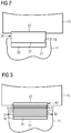
- Figure 1
- shows a schematic sectional view fluid film bearing for a wind turbine according to the present invention.
- Figure 2
- shows a schematic sectional view of a first embodiment for a component of the fluid film bearing of
Figure 1 . - Figure 3
- shows a schematic sectional view of a second embodiment for the component of the fluid film bearing of
Figure 1 . - The illustrations in the drawings are schematic. It is noted that in different figures, similar or identical elements or features are provided with the same reference signs. In order to avoid unnecessary repetitions elements or features which have already been described with respect to an embodiment are not described again further in the description.
-
Figure 1 partially shows a fluid bearing 10 for a wind turbine (not represented as a whole). The fluid bearing 10 includes astator portion 10a and a rotor portion (not shown as not being a specific object of the present invention), typically a shaft, rotating with respect to thestator portion 10a around a longitudinal axis Y of the fluid bearing. - In the following the terms "longitudinal", "radial" and "circumferential" are referred, when not differently specified, to the longitudinal axis Y of the fluid bearing 10.
- The
stator portion 10a comprises a plurality ofbearing pads 15. In operation of the fluid bearing 10, a thin layer of rapidly moving pressurized liquid or gas is established between the rotor portion and thebearing pads 15. The lack of contact between the moving parts implies that there is no sliding friction, reducing wear and vibration with respect to other types of bearings. How such this thin fluid layer is established is not a specific object of the present invention and therefore not described in further detail. - The fluid bearing 10, in the
stator portion 10a, includes a bearinghousing 11 having a hollow shape circumferentially distributed around the longitudinal axis Y. - The
bearing housing 11 comprises aninner surface 13 longitudinally extended. The plurality ofbearing pads 15 are provided inside the bearinghousing 11, protruding radially from the innercylindrical surface 13 towards the longitudinal axis Y. Thebearing pads 15 are circumferentially distributed around the longitudinal axis Y. The distribution is not regular but takes into account that on a lower portion of the bearinghousing 11, due to the gravity, the load is greater. Therefore, with reference toFigure 1 , which represents a vertical sectional view of the fluid bearing 10 in operative position, twobearing pads 15 are provided on a horizontal plane including the longitudinal axis Y, fourbearing pads 15 are provided on an upper portion of thebearing housing 11 above the horizontal plane including the longitudinal axis Y and eightbearing pads 15 are provided on an lower portion of thebearing housing 11 below the horizontal plane including the longitudinal axis Y. - According to other possible embodiments of the present invention, a different number and a different distribution of the
plurality bearing pads 15 may be implemented. - For each of the
bearing pads 15, thefluid bearing 10 includes a supportingstructure 20 for connecting therespective bearing pad 15 to the bearinghousing 11. - Each supporting
structure 20 comprises afirst interface 21 connected to arespective seat 18 provided in the bearinghousing 11. In particular each supportingstructure 20 may be connected to therespective seat 18 through the respectivefirst interface 21 in a removable manner, so that the supportingstructure 20 and therespective bearing pad 15 attached thereto may be, if necessary, removed and substituted with another supportingstructure 20. This may happen, for example, for maintenance purposes or when reconfiguring thefluid bearing 10 by substituting one embodiment of supportingstructure 20 with another embodiment of supportingstructure 20. - The
seat 18 is a radial recess provided on theinner surface 13 of the bearinghousing 11 and has the shape of a parallelepiped having an opening on theinner surface 13, a plane base opposite to the opening and four plane lateral surfaces connecting the plane base to the opening. - The plane base of the
seat 18 is orthogonal to a radial direction thefluid bearing 10. The four plane lateral surfaces of theseat 18 are orthogonal to a circumferential direction thefluid bearing 10, i.e. practically almost oriented according to a radial direction of thefluid bearing 10. - Consequently, the
first interface 21 as a parallelepiped shape for matching the radial recess of theseat 18. - The supporting
structure 20 further includes asecond interface 22 for connecting the supportingstructure 20 to therespective bearing pad 15. Thesecond interface 22 is provided in the supportingstructure 20 radially opposite to thefirst interface 21. In particular each supportingstructure 20 may be connected to therespective bearing pad 15 through the respectivesecond interface 22 in a removable manner, so that thebearing pad 15 may be, if necessary for example during maintenance of thefluid bearing 10, removed and substituted with anotherbearing pad 15. - According to the present invention, the supporting
structure 20 comprises anelastomer 30 allowing tilting of therespective bearing pad 15. Theelastomer 30 is interposed between therespective seat 18 and therespective bearing pad 15. - According to respective embodiments of the present invention, bearing
pad 15 may tilt parallel to the longitudinal axis Y, i.e. in the plane of the attached figures, or about a direction orthogonal to the longitudinal axis Y or about both directions. - With reference to
Figure 2 , a first embodiment of the supportingstructure 20 is shown. Such supportingstructure 20 comprises 2 anelastomer 30 provided as an elastomeric layer between therespective seat 18 and therespective bearing pad 15. Theelastomeric layer 30 contacts therespective seat 18, thefirst interface 21 being therefore provided on theelastomeric layer 30. The supportingstructure 20 further include aliner 32 made of steel, extending between theelastomeric layer 30 and therespective bearing pad 15. Thesecond interface 22 is therefore provided on theliner 32. - According to an alternative embodiment (not shown) of the present invention the radial positions of the
elastomeric layer 30 and of thesteel liner 32 are inverted, theelastomeric layer 30 being in contact with therespective bearing pad 15 and thesteel liner 32 being in contact with therespective seat 18. - According to another alternative embodiment (not shown) of the present invention the radial position of the
elastomer layer 30 is intermediate between therespective seat 18 and therespective bearing pad 15. - With reference to
Figure 3 , a second embodiment of the supportingstructure 20 is shown. Such supportingstructure 20 comprises a plurality ofelastomeric layers 30 and a plurality ofsteel plates 31, eachelastomeric layer 30 being radially interposed between twosteel plates 31. - The pluralities of
elastomeric layers 30 and ofsteel plates 31 constitutes astack 40 where eachelastomeric layer 30 is interposed between twosteel plates 31 and eachsteel plate 31 is interposed between twoelastomeric layer 30. - The
stack 40 extends between therespective seat 18 and therespective bearing pad 15, thefirst interface 21 and thesecond interface 22 being respectively provided on tworespective steel plates 31. - The radial thickness and size of the
elastomeric layers 30 and of thesteel plates 31 are adjusted to achieve the limiting torsional moment about the longitudinal axis Y, which is needed for the alignment of thebearing pad 15. - According to alternative embodiments (not shown) one or both of the
first interface 21 and thesecond interface 22 are provided on respective elastomeric layers 30. - It should be noted that the term "comprising" does not exclude other elements or steps and the use of articles "a" or "an" does not exclude a plurality. Also elements described in association with different embodiments may be combined. It should also be noted that reference signs in the claims should not be construed as limiting the scope of the claims.
Claims (7)
- A fluid bearing (10) for a wind turbine comprising:a bearing housing (11),a plurality of bearing pads (15) inside the bearing housing (11) and circumferentially distributed around a longitudinal axis (Y) of the fluid bearing (10),a plurality of supporting structures (20), each supporting structure (20) having at least a first interface (21) connected to a respective seat (18) provided in the bearing housing (11) and at least a second interface (22) connected to a respective bearing pad (15) of the plurality of bearing pads (15),wherein the supporting structure (20) comprises an elastomer (30) allowing tilting of the respective bearing pad (15), the elastomer (30) being interposed between the respective seat (18) and the respective bearing pad (15).
- The fluid bearing (10) of claim 1, wherein the elastomer (30) allowing tilting of the respective bearing pad (15) parallel and/or orthogonal to the longitudinal axis (Y).
- The fluid bearing (10) of claim 1 or 2, wherein the elastomer (30) is provided as elastomeric layer between the respective seat (18) and the respective bearing pad (15).
- The fluid bearing (10) of claim 1 or 2 or 3, wherein the elastomer (30) contacts the respective seat (18).
- The fluid bearing (10) of claim 3 or 4, wherein a plurality of elastomeric layers (30) are provided, each elastomeric layer (30) being interposed between two steel plates (31).
- The fluid bearing (10) of claim 5, comprising a stack (40) constituted of a plurality of elastomeric layers (30) and of elastomeric steel plates (31), each elastomeric layer (30) being interposed between two steel plates (31), each steel plate (31) being interposed between two elastomeric layer (30) .
- The fluid bearing (10) of claim 6, wherein the stack (40) extends between the respective seat (18) and the respective bearing pad (15).
Priority Applications (5)
| Application Number | Priority Date | Filing Date | Title |
|---|---|---|---|
| EP17192112.5A EP3460269A1 (en) | 2017-09-20 | 2017-09-20 | Fluid film bearing for a wind turbine |
| EP18782328.1A EP3662168B1 (en) | 2017-09-20 | 2018-09-19 | Fluid film bearing for a wind turbine |
| US16/648,868 US11274698B2 (en) | 2017-09-20 | 2018-09-19 | Fluid film bearing for a wind turbine |
| CN201880061411.8A CN111094773A (en) | 2017-09-20 | 2018-09-19 | Fluid film bearing for wind turbine |
| PCT/EP2018/075321 WO2019057753A1 (en) | 2017-09-20 | 2018-09-19 | Fluid film bearing for a wind turbine |
Applications Claiming Priority (1)
| Application Number | Priority Date | Filing Date | Title |
|---|---|---|---|
| EP17192112.5A EP3460269A1 (en) | 2017-09-20 | 2017-09-20 | Fluid film bearing for a wind turbine |
Publications (1)
| Publication Number | Publication Date |
|---|---|
| EP3460269A1 true EP3460269A1 (en) | 2019-03-27 |
Family
ID=59923320
Family Applications (2)
| Application Number | Title | Priority Date | Filing Date |
|---|---|---|---|
| EP17192112.5A Withdrawn EP3460269A1 (en) | 2017-09-20 | 2017-09-20 | Fluid film bearing for a wind turbine |
| EP18782328.1A Active EP3662168B1 (en) | 2017-09-20 | 2018-09-19 | Fluid film bearing for a wind turbine |
Family Applications After (1)
| Application Number | Title | Priority Date | Filing Date |
|---|---|---|---|
| EP18782328.1A Active EP3662168B1 (en) | 2017-09-20 | 2018-09-19 | Fluid film bearing for a wind turbine |
Country Status (4)
| Country | Link |
|---|---|
| US (1) | US11274698B2 (en) |
| EP (2) | EP3460269A1 (en) |
| CN (1) | CN111094773A (en) |
| WO (1) | WO2019057753A1 (en) |
Cited By (8)
| Publication number | Priority date | Publication date | Assignee | Title |
|---|---|---|---|---|
| EP3739227A1 (en) * | 2019-04-30 | 2020-11-18 | General Electric Company | Bearing for a wind turbine drivetrain having an elastomer support |
| CN113565708A (en) * | 2020-04-28 | 2021-10-29 | 西门子歌美飒可再生能源公司 | Fluid film bearing and wind turbine |
| US11248590B2 (en) | 2019-05-16 | 2022-02-15 | Siemens Gamesa Renewable Energy A/S | Bearing arrangement for a wind turbine and wind turbine |
| US11293483B2 (en) | 2019-05-16 | 2022-04-05 | Siemens Gamesa Renewable Energy A/S | Bearing arrangement for a wind turbine and wind turbine |
| AT524464A1 (en) * | 2020-11-30 | 2022-06-15 | Miba Gleitlager Austria Gmbh | Method for assembling a rotor bearing of a wind turbine |
| US11428213B2 (en) | 2019-05-16 | 2022-08-30 | Siemens Gamesa Renewable Energy A/S | Bearing arrangement for a wind turbine and wind turbine |
| US11441547B2 (en) | 2019-05-16 | 2022-09-13 | Siemens Gamesa Renewable Energy A/S | Bearing arrangement for a wind turbine and wind turbine |
| US11927176B2 (en) | 2019-09-16 | 2024-03-12 | Siemens Gamesa Renewable Energy A/S | Bearing arrangement for a wind turbine and wind turbine |
Families Citing this family (2)
| Publication number | Priority date | Publication date | Assignee | Title |
|---|---|---|---|---|
| CN112922957A (en) * | 2021-03-05 | 2021-06-08 | 上海电气风电集团股份有限公司 | Elastic tilting bearing bush sliding bearing of wind turbine |
| JP2022157529A (en) * | 2021-03-31 | 2022-10-14 | 三菱重工業株式会社 | fluid film bearing |
Citations (3)
| Publication number | Priority date | Publication date | Assignee | Title |
|---|---|---|---|---|
| US3930691A (en) * | 1974-04-12 | 1976-01-06 | Jerome Greene | Swing pad bearing |
| US4268094A (en) * | 1977-01-06 | 1981-05-19 | Jerome Greene | Radial and thrust-type hydrodynamic bearing capable of accommodating misalignment |
| US4286828A (en) * | 1979-11-28 | 1981-09-01 | The United States Of America As Represented By The Secretary Of The Navy | Offset-pad bearing |
Family Cites Families (8)
| Publication number | Priority date | Publication date | Assignee | Title |
|---|---|---|---|---|
| US1895936A (en) * | 1928-10-31 | 1933-01-31 | Goodrich Co B F | Rubber shaft-bearing |
| US3033619A (en) * | 1957-03-28 | 1962-05-08 | Elin Ag Fur Elek Sche Ind | Thrust bearing for large machines, especially electric machines |
| US3932004A (en) * | 1975-02-06 | 1976-01-13 | The B. F. Goodrich Company | Rubber bearing with non-metallic support member |
| GB1592033A (en) * | 1978-01-18 | 1981-07-01 | Greene J | Hydrodynamic bearing with radial thrust and moment load capacity |
| US4515486A (en) * | 1984-02-03 | 1985-05-07 | Ide Russell D | Elastomeric supported hydrodynamic bearing |
| DK2376797T3 (en) | 2008-12-15 | 2016-08-22 | Jochen Corts | Segmented composite bearings and wind generator that uses hydraulic pump / motor combination |
| DE102016202167A1 (en) * | 2016-02-12 | 2017-08-17 | Robert Bosch Gmbh | tilting pad |
| ES2836226T3 (en) * | 2017-09-20 | 2021-06-24 | Siemens Gamesa Renewable Energy As | Thrust bearing for a wind turbine |
-
2017
- 2017-09-20 EP EP17192112.5A patent/EP3460269A1/en not_active Withdrawn
-
2018
- 2018-09-19 CN CN201880061411.8A patent/CN111094773A/en active Pending
- 2018-09-19 US US16/648,868 patent/US11274698B2/en active Active
- 2018-09-19 EP EP18782328.1A patent/EP3662168B1/en active Active
- 2018-09-19 WO PCT/EP2018/075321 patent/WO2019057753A1/en unknown
Patent Citations (3)
| Publication number | Priority date | Publication date | Assignee | Title |
|---|---|---|---|---|
| US3930691A (en) * | 1974-04-12 | 1976-01-06 | Jerome Greene | Swing pad bearing |
| US4268094A (en) * | 1977-01-06 | 1981-05-19 | Jerome Greene | Radial and thrust-type hydrodynamic bearing capable of accommodating misalignment |
| US4286828A (en) * | 1979-11-28 | 1981-09-01 | The United States Of America As Represented By The Secretary Of The Navy | Offset-pad bearing |
Cited By (10)
| Publication number | Priority date | Publication date | Assignee | Title |
|---|---|---|---|---|
| EP3739227A1 (en) * | 2019-04-30 | 2020-11-18 | General Electric Company | Bearing for a wind turbine drivetrain having an elastomer support |
| US11174895B2 (en) | 2019-04-30 | 2021-11-16 | General Electric Company | Bearing for a wind turbine drivetrain having an elastomer support |
| US11248590B2 (en) | 2019-05-16 | 2022-02-15 | Siemens Gamesa Renewable Energy A/S | Bearing arrangement for a wind turbine and wind turbine |
| US11293483B2 (en) | 2019-05-16 | 2022-04-05 | Siemens Gamesa Renewable Energy A/S | Bearing arrangement for a wind turbine and wind turbine |
| US11428213B2 (en) | 2019-05-16 | 2022-08-30 | Siemens Gamesa Renewable Energy A/S | Bearing arrangement for a wind turbine and wind turbine |
| US11441547B2 (en) | 2019-05-16 | 2022-09-13 | Siemens Gamesa Renewable Energy A/S | Bearing arrangement for a wind turbine and wind turbine |
| US11927176B2 (en) | 2019-09-16 | 2024-03-12 | Siemens Gamesa Renewable Energy A/S | Bearing arrangement for a wind turbine and wind turbine |
| CN113565708A (en) * | 2020-04-28 | 2021-10-29 | 西门子歌美飒可再生能源公司 | Fluid film bearing and wind turbine |
| AT524464A1 (en) * | 2020-11-30 | 2022-06-15 | Miba Gleitlager Austria Gmbh | Method for assembling a rotor bearing of a wind turbine |
| AT524464B1 (en) * | 2020-11-30 | 2022-07-15 | Miba Gleitlager Austria Gmbh | Method for assembling a rotor bearing of a wind turbine |
Also Published As
| Publication number | Publication date |
|---|---|
| EP3662168B1 (en) | 2022-09-07 |
| WO2019057753A1 (en) | 2019-03-28 |
| CN111094773A (en) | 2020-05-01 |
| US11274698B2 (en) | 2022-03-15 |
| EP3662168A1 (en) | 2020-06-10 |
| US20200284292A1 (en) | 2020-09-10 |
Similar Documents
| Publication | Publication Date | Title |
|---|---|---|
| EP3460269A1 (en) | Fluid film bearing for a wind turbine | |
| EP3460271B1 (en) | Fluid film bearing for a wind turbine | |
| EP1770318B1 (en) | Bearing assembly and centering support structure therefor | |
| US10612586B2 (en) | Thrust bearing for a wind turbine | |
| US4462700A (en) | Hydrodynamic fluid film thrust bearing | |
| KR101290922B1 (en) | Direct-drive wind turbine generator and bearing structure | |
| WO2018166663A1 (en) | Sliding bearing pad support | |
| US20120261536A1 (en) | Compliant bearing mount | |
| US20160123388A1 (en) | Rotating machine with at least one active magnetic bearing and spaced auxiliary rolling bearings | |
| CN103299066B (en) | The bearing assembly of ship turbine arbor and comprise the cruising turbine of this bearing assembly | |
| US4402618A (en) | High speed rotary machine bearing mount structure | |
| US6948853B2 (en) | High load capacity stacked foil thrust bearing assembly | |
| US20040066991A1 (en) | High load capacity foil thrust bearings | |
| CN101338790B (en) | Gas/ solid two-phase composite gyration basic method and device | |
| CN115289056A (en) | Pump thrust bearing with self-balancing rotor tilting function | |
| CN114033790A (en) | Combined air-float thrust bearing and mechanical equipment | |
| CN113669369A (en) | Active control gas tilting pad bearing | |
| JP2020193698A (en) | Spindle device and motor device | |
| JPH03265714A (en) | Thrust gas bearing device |
Legal Events
| Date | Code | Title | Description |
|---|---|---|---|
| PUAI | Public reference made under article 153(3) epc to a published international application that has entered the european phase |
Free format text: ORIGINAL CODE: 0009012 |
|
| AK | Designated contracting states |
Kind code of ref document: A1 Designated state(s): AL AT BE BG CH CY CZ DE DK EE ES FI FR GB GR HR HU IE IS IT LI LT LU LV MC MK MT NL NO PL PT RO RS SE SI SK SM TR |
|
| AX | Request for extension of the european patent |
Extension state: BA ME |
|
| STAA | Information on the status of an ep patent application or granted ep patent |
Free format text: STATUS: THE APPLICATION IS DEEMED TO BE WITHDRAWN |
|
| 18D | Application deemed to be withdrawn |
Effective date: 20190928 |