EP3460200A1 - Turbine frame for a gas turbine engine, corresponding gas turbine engine and assembly method a turbine frame - Google Patents
Turbine frame for a gas turbine engine, corresponding gas turbine engine and assembly method a turbine frame Download PDFInfo
- Publication number
- EP3460200A1 EP3460200A1 EP18196691.2A EP18196691A EP3460200A1 EP 3460200 A1 EP3460200 A1 EP 3460200A1 EP 18196691 A EP18196691 A EP 18196691A EP 3460200 A1 EP3460200 A1 EP 3460200A1
- Authority
- EP
- European Patent Office
- Prior art keywords
- turbine
- end portion
- bearing support
- support housing
- tie rod
- Prior art date
- Legal status (The legal status is an assumption and is not a legal conclusion. Google has not performed a legal analysis and makes no representation as to the accuracy of the status listed.)
- Granted
Links
Images



Classifications
-
- F—MECHANICAL ENGINEERING; LIGHTING; HEATING; WEAPONS; BLASTING
- F01—MACHINES OR ENGINES IN GENERAL; ENGINE PLANTS IN GENERAL; STEAM ENGINES
- F01D—NON-POSITIVE DISPLACEMENT MACHINES OR ENGINES, e.g. STEAM TURBINES
- F01D25/00—Component parts, details, or accessories, not provided for in, or of interest apart from, other groups
- F01D25/16—Arrangement of bearings; Supporting or mounting bearings in casings
- F01D25/162—Bearing supports
-
- F—MECHANICAL ENGINEERING; LIGHTING; HEATING; WEAPONS; BLASTING
- F01—MACHINES OR ENGINES IN GENERAL; ENGINE PLANTS IN GENERAL; STEAM ENGINES
- F01D—NON-POSITIVE DISPLACEMENT MACHINES OR ENGINES, e.g. STEAM TURBINES
- F01D25/00—Component parts, details, or accessories, not provided for in, or of interest apart from, other groups
- F01D25/24—Casings; Casing parts, e.g. diaphragms, casing fastenings
-
- F—MECHANICAL ENGINEERING; LIGHTING; HEATING; WEAPONS; BLASTING
- F01—MACHINES OR ENGINES IN GENERAL; ENGINE PLANTS IN GENERAL; STEAM ENGINES
- F01D—NON-POSITIVE DISPLACEMENT MACHINES OR ENGINES, e.g. STEAM TURBINES
- F01D9/00—Stators
- F01D9/02—Nozzles; Nozzle boxes; Stator blades; Guide conduits, e.g. individual nozzles
- F01D9/04—Nozzles; Nozzle boxes; Stator blades; Guide conduits, e.g. individual nozzles forming ring or sector
- F01D9/041—Nozzles; Nozzle boxes; Stator blades; Guide conduits, e.g. individual nozzles forming ring or sector using blades
-
- F—MECHANICAL ENGINEERING; LIGHTING; HEATING; WEAPONS; BLASTING
- F01—MACHINES OR ENGINES IN GENERAL; ENGINE PLANTS IN GENERAL; STEAM ENGINES
- F01D—NON-POSITIVE DISPLACEMENT MACHINES OR ENGINES, e.g. STEAM TURBINES
- F01D9/00—Stators
- F01D9/06—Fluid supply conduits to nozzles or the like
- F01D9/065—Fluid supply or removal conduits traversing the working fluid flow, e.g. for lubrication-, cooling-, or sealing fluids
-
- F—MECHANICAL ENGINEERING; LIGHTING; HEATING; WEAPONS; BLASTING
- F02—COMBUSTION ENGINES; HOT-GAS OR COMBUSTION-PRODUCT ENGINE PLANTS
- F02C—GAS-TURBINE PLANTS; AIR INTAKES FOR JET-PROPULSION PLANTS; CONTROLLING FUEL SUPPLY IN AIR-BREATHING JET-PROPULSION PLANTS
- F02C7/00—Features, components parts, details or accessories, not provided for in, or of interest apart form groups F02C1/00 - F02C6/00; Air intakes for jet-propulsion plants
- F02C7/20—Mounting or supporting of plant; Accommodating heat expansion or creep
-
- F—MECHANICAL ENGINEERING; LIGHTING; HEATING; WEAPONS; BLASTING
- F05—INDEXING SCHEMES RELATING TO ENGINES OR PUMPS IN VARIOUS SUBCLASSES OF CLASSES F01-F04
- F05D—INDEXING SCHEME FOR ASPECTS RELATING TO NON-POSITIVE-DISPLACEMENT MACHINES OR ENGINES, GAS-TURBINES OR JET-PROPULSION PLANTS
- F05D2220/00—Application
- F05D2220/30—Application in turbines
- F05D2220/32—Application in turbines in gas turbines
- F05D2220/323—Application in turbines in gas turbines for aircraft propulsion, e.g. jet engines
-
- F—MECHANICAL ENGINEERING; LIGHTING; HEATING; WEAPONS; BLASTING
- F05—INDEXING SCHEMES RELATING TO ENGINES OR PUMPS IN VARIOUS SUBCLASSES OF CLASSES F01-F04
- F05D—INDEXING SCHEME FOR ASPECTS RELATING TO NON-POSITIVE-DISPLACEMENT MACHINES OR ENGINES, GAS-TURBINES OR JET-PROPULSION PLANTS
- F05D2230/00—Manufacture
- F05D2230/60—Assembly methods
-
- F—MECHANICAL ENGINEERING; LIGHTING; HEATING; WEAPONS; BLASTING
- F05—INDEXING SCHEMES RELATING TO ENGINES OR PUMPS IN VARIOUS SUBCLASSES OF CLASSES F01-F04
- F05D—INDEXING SCHEME FOR ASPECTS RELATING TO NON-POSITIVE-DISPLACEMENT MACHINES OR ENGINES, GAS-TURBINES OR JET-PROPULSION PLANTS
- F05D2240/00—Components
- F05D2240/10—Stators
- F05D2240/12—Fluid guiding means, e.g. vanes
-
- F—MECHANICAL ENGINEERING; LIGHTING; HEATING; WEAPONS; BLASTING
- F05—INDEXING SCHEMES RELATING TO ENGINES OR PUMPS IN VARIOUS SUBCLASSES OF CLASSES F01-F04
- F05D—INDEXING SCHEME FOR ASPECTS RELATING TO NON-POSITIVE-DISPLACEMENT MACHINES OR ENGINES, GAS-TURBINES OR JET-PROPULSION PLANTS
- F05D2240/00—Components
- F05D2240/10—Stators
- F05D2240/14—Casings or housings protecting or supporting assemblies within
-
- F—MECHANICAL ENGINEERING; LIGHTING; HEATING; WEAPONS; BLASTING
- F05—INDEXING SCHEMES RELATING TO ENGINES OR PUMPS IN VARIOUS SUBCLASSES OF CLASSES F01-F04
- F05D—INDEXING SCHEME FOR ASPECTS RELATING TO NON-POSITIVE-DISPLACEMENT MACHINES OR ENGINES, GAS-TURBINES OR JET-PROPULSION PLANTS
- F05D2250/00—Geometry
- F05D2250/20—Three-dimensional
- F05D2250/23—Three-dimensional prismatic
- F05D2250/232—Three-dimensional prismatic conical
-
- F—MECHANICAL ENGINEERING; LIGHTING; HEATING; WEAPONS; BLASTING
- F05—INDEXING SCHEMES RELATING TO ENGINES OR PUMPS IN VARIOUS SUBCLASSES OF CLASSES F01-F04
- F05D—INDEXING SCHEME FOR ASPECTS RELATING TO NON-POSITIVE-DISPLACEMENT MACHINES OR ENGINES, GAS-TURBINES OR JET-PROPULSION PLANTS
- F05D2260/00—Function
- F05D2260/30—Retaining components in desired mutual position
- F05D2260/37—Retaining components in desired mutual position by a press fit connection
-
- Y—GENERAL TAGGING OF NEW TECHNOLOGICAL DEVELOPMENTS; GENERAL TAGGING OF CROSS-SECTIONAL TECHNOLOGIES SPANNING OVER SEVERAL SECTIONS OF THE IPC; TECHNICAL SUBJECTS COVERED BY FORMER USPC CROSS-REFERENCE ART COLLECTIONS [XRACs] AND DIGESTS
- Y02—TECHNOLOGIES OR APPLICATIONS FOR MITIGATION OR ADAPTATION AGAINST CLIMATE CHANGE
- Y02T—CLIMATE CHANGE MITIGATION TECHNOLOGIES RELATED TO TRANSPORTATION
- Y02T50/00—Aeronautics or air transport
- Y02T50/60—Efficient propulsion technologies, e.g. for aircraft
Definitions
- This disclosure relates to a turbine frame assembly for a gas turbine engine, and more particularly to a turbine frame that supports a bearing.
- a gas turbine engine typically includes a fan section, a compressor section, a combustor section, and a turbine section. Air entering the compressor section is compressed and delivered into the combustion section where it is mixed with fuel and ignited to generate a high-speed exhaust gas flow. The high-speed exhaust gas flow expands through the turbine section to drive the compressor and the fan section.
- Some turbine engines include a turbine frame in the turbine section that transfers loads between a bearing and other portions of the engine static structure.
- a turbine frame for a gas turbine engine includes a turbine case, a bearing support housing that defines a receptacle, and a tie rod preloaded in compression between the turbine case and the bearing support housing.
- the tie rod includes a first end portion and a second end portion
- the bearing support housing defines a receptacle that at least partially receives the second end portion, with walls of the receptacle that have a complementary geometry with walls of the second end portion.
- surfaces of the second end portion are spaced apart from surfaces of the receptacle to define a frame cavity.
- the tie rod is a plurality of tie rods.
- the receptacle is a plurality of receptacles circumferentially distributed about an axis of the bearing support housing. Each of the plurality of tie rods is preloaded in compression between the turbine case and the bearing support housing.
- a further embodiment of any of the foregoing embodiments includes a retention member moveable relative to the tie rod to compress the tie rod between the turbine case and the receptacle.
- a further embodiment of any of the foregoing embodiments includes a lock ring engageable with the retention member to limit relative rotation of the turbine case and the tie rod.
- the retention member is threadably secured to a first end portion of the tie rod, and is slidably received in a socket defined by the turbine case, with the tie rod translatable relative to the socket in response to rotation of the retention member about the first end portion.
- the retention member, the lock ring and the tie rod define respective sections of a flow path between the turbine case and a cavity defined by the receptacle.
- a further embodiment of any of the foregoing embodiments includes a vane that defines a core flow path, the tie rod extending through the vane.
- a gas turbine engine includes a fan section that has a fan, a compressor section, and a turbine section that drives at least one of the fan section and the compressor section through a shaft.
- the turbine section has a turbine frame that extends along an engine axis between a first turbine and a second turbine that define a core flow path.
- the turbine frame includes a bearing support housing that has a bearing that supports the shaft, a turbine case that at least partially surrounds the bearing support housing, and a plurality of tie rods each preloaded in compression between the turbine case and the bearing support housing.
- the bearing support housing defines a plurality of receptacles defined about an outer periphery of the bearing support housing, an inner periphery of the turbine case defines a plurality of sockets, and each of the plurality of tie rods includes a first end portion and a second end portion. The first end portion received in a respective one of the plurality of sockets, and the second end portion seated against surfaces of a respective one of the plurality of receptacles.
- each socket of the plurality of sockets is axially offset from a respective receptacle of the plurality of receptacles by a predetermined distance with respect to the engine axis.
- a further embodiment of any of the foregoing embodiments includes a plurality of retention members each moveable relative to the first end portion of a respective one of the plurality of tie rods to cause the first end portion to translate along a first axis such that the second end portion is brought into direct abutment with surfaces of a respective one of the plurality of receptacles.
- each of the plurality of tie rods is translatable along a first axis that is oblique to the engine axis.
- the plurality of retention members and the plurality of tie rods define a plurality of flow paths between a fluid source and the plurality of receptacles, and the plurality of receptacles is in fluid communication with at least one airflow compartment defined by one of the first and second turbines.
- a further embodiment of any of the foregoing embodiments includes a plurality of vanes each having an airfoil section that extend between a first platform and a second platform that bound radially inner and radially outer portions of the core flow path, and each of the plurality of tie rods extending through the airfoil section of a respective one of the plurality of vanes.
- a method of assembling a turbine frame according to an embodiment of the present invention includes moving a bearing support housing at least partially received in a turbine case, and coupling a tie rod to the turbine case and to the bearing support housing such that the tie rod is preloaded in compression.
- a further embodiment of any of the foregoing embodiments includes positioning a first end portion of the tie rod into a socket defined by an inner periphery of the turbine case; and translating the tie rod along an axis defined by the socket such that a second end portion of the tie rod directly abuts against surfaces of a receptacle defined by an outer periphery of the bearing support housing.
- walls of the receptacle engage a perimeter of the second end portion to limit rotation of the tie rod about the axis.
- a further embodiment of any of the foregoing embodiments includes communicating fluid through a fluid passage defined by the tie rod.
- the fluid passage interconnects a fluid source and a cavity defined between the second end portion and the receptacle.
- FIG. 1 schematically illustrates a gas turbine engine 20.
- the gas turbine engine 20 is disclosed herein as a two-spool turbofan that generally incorporates a fan section 22, a compressor section 24, a combustor section 26 and a turbine section 28.
- Alternative engines might include an augmentor section (not shown) among other systems or features.
- the fan section 22 drives air along a bypass flow path B in a bypass duct defined within a nacelle 15, while the compressor section 24 drives air along a core flow path C for compression and communication into the combustor section 26 then expansion through the turbine section 28.
- the exemplary engine 20 generally includes a low speed spool 30 and a high speed spool 32 mounted for rotation about an engine central longitudinal axis A relative to an engine static structure 36 via several bearing systems 38. It should be understood that various bearing systems 38 at various locations may alternatively or additionally be provided, and the location of bearing systems 38 may be varied as appropriate to the application.
- the low speed spool 30 generally includes an inner shaft 40 that interconnects a fan 42, a first (or low) pressure compressor 44 and a first (or low) pressure turbine 46.
- the inner shaft 40 is connected to the fan 42 through a speed change mechanism, which in exemplary gas turbine engine 20 is illustrated as a geared architecture 48 to drive the fan 42 at a lower speed than the low speed spool 30.
- the high speed spool 32 includes an outer shaft 50 that interconnects a second (or high) pressure compressor 52 and a second (or high) pressure turbine 54.
- a combustor 56 is arranged in exemplary gas turbine 20 between the high pressure compressor 52 and the high pressure turbine 54.
- a mid-turbine frame 57 of the engine static structure 36 is arranged generally between the high pressure turbine 54 and the low pressure turbine 46.
- the mid-turbine frame 57 further supports bearing systems 38 in the turbine section 28.
- the inner shaft 40 and the outer shaft 50 are concentric and rotate via bearing systems 38 about the engine central longitudinal axis A which is collinear with their longitudinal axes.
- the core airflow is compressed by the low pressure compressor 44 then the high pressure compressor 52, mixed and burned with fuel in the combustor 56, then expanded over the high pressure turbine 54 and low pressure turbine 46.
- the mid-turbine frame 57 includes airfoils 59 which are in the core airflow path C.
- the turbines 46, 54 rotationally drive the respective low speed spool 30 and high speed spool 32 in response to the expansion.
- gear system 48 may be located aft of combustor section 26 or even aft of turbine section 28, and fan section 22 may be positioned forward or aft of the location of gear system 48.
- the engine 20 in one example is a high-bypass geared aircraft engine.
- the engine 20 bypass ratio is greater than about six, with an example embodiment being greater than about ten
- the geared architecture 48 is an epicyclic gear train, such as a planetary gear system or other gear system, with a gear reduction ratio of greater than about 2.3 and the low pressure turbine 46 has a pressure ratio that is greater than about five.
- the engine 20 bypass ratio is greater than about ten
- the fan diameter is significantly larger than that of the low pressure compressor 44
- the low pressure turbine 46 has a pressure ratio that is greater than about five.
- Low pressure turbine 46 pressure ratio is pressure measured prior to inlet of low pressure turbine 46 as related to the pressure at the outlet of the low pressure turbine 46 prior to an exhaust nozzle.
- the geared architecture 48 may be an epicycle gear train, such as a planetary gear system or other gear system, with a gear reduction ratio of greater than about 2.3:1. It should be understood, however, that the above parameters are only exemplary of one embodiment of a geared architecture engine and that the present invention is applicable to other gas turbine engines including direct drive turbofans.
- the fan section 22 of the engine 20 is designed for a particular flight condition -- typically cruise at about 0.8 Mach and about 10,668 m (35,000 feet).
- "Low fan pressure ratio” is the pressure ratio across the fan blade alone, without a Fan Exit Guide Vane (“FEGV”) system.
- the low fan pressure ratio as disclosed herein according to one non-limiting embodiment is less than about 1.45.
- the "Low corrected fan tip speed” as disclosed herein according to one non-limiting embodiment is less than about 351 m/second (1150 ft / second).
- the turbine section 28 can include alternating rows of rotor assemblies and vane assemblies that carry airfoils that extend into the core flow path C.
- the rotor assemblies can carry a plurality of rotating blades 25, while each vane assembly can carry a plurality of vanes 27 that extend into the core flow path C.
- the vanes 27 of the vane assemblies direct the core airflow to the blades 25.
- the blades 25 extract energy (in the form of pressure) that is communicated through the gas turbine engine 20 along the core flow path C.
- FIG 2 is a schematic perspective view of the mid-turbine frame 57.
- the mid-turbine frame 57 includes an outer frame case 62 and a bearing support member or housing 70 coaxially arranged about a frame axis B.
- the frame axis B can be aligned with the engine axis A ( Figure 1 ).
- the mid-turbine frame 57 is arranged axially between the low pressure turbine 46 (or first turbine) and the high pressure turbine 54 (or second turbine) shown in Figure 1 .
- One or more spokes or tie rods 66 are distributed about the bearing support housing 70 and extend radially between an inner periphery 62A of the outer frame case 62 and an outer periphery 70B of the bearing support housing 70 to provide structural support.
- the axial and radial directions are in relation to the frame axis B unless stated otherwise.
- the bearing support housing 70 supports the rotor assembly via the bearing system 38 (shown in Figure 1 ) located in a bearing compartment BC, and distributes forces from the bearing support housing 70 to the outer frame case 62 via the tie rods 66.
- the outer frame case 62 is configured to transfer loads from the bearing support housing 70 to other portions of the engine static structure 36 (shown in Figure 1 ).
- one or more tie rods 66 A define cooling passage(s) 55 (shown schematically in dashed line) to communicate cooling airflow from a fluid or coolant source 67 to the bearing system 38 or to a rotor assembly of the turbine section 28.
- Coolant sources 67 can include bleed air from an upstream stage of the compressor section 24, bypass air, or a secondary cooling system aboard the aircraft, for example.
- One or more service lines 68 are distributed around the circumference of the bearing support housing 70 to provide a path between the outer frame case 62 and the bearing support housing 70.
- the service lines 68 are positioned between adjacent pairs of tie rods 66.
- the service lines 68 can include, but are not limited to, a conduit, a pressurized lubrication or oil supply line 68 A , a lubrication or oil scavenge line 68 B , a coolant supply line 68 C coupled to the coolant source 67, and a secondary lubrication or oil drain line 68 D , for example.
- the lubrication supply and scavenge lines 68 A , 68 B are configured to communicate lubricant between the bearing system 38 and a lubrication source 69, which can include a reservoir and lubrication pump, for example, such that the bearing system 38 is lubricated and cooled during operation of the engine 20.
- a lubrication source 69 which can include a reservoir and lubrication pump, for example, such that the bearing system 38 is lubricated and cooled during operation of the engine 20.
- a lubrication source 69 which can include a reservoir and lubrication pump, for example, such that the bearing system 38 is lubricated and cooled during operation of the engine 20.
- the outer frame case 62 defines a plurality of sockets 62B distributed about the frame axis B.
- the tie rods 66 and service lines 68 together with the bearing support housing 70 define a plurality of locating features 79 distributed about the frame case B.
- the locating features 79 are configured to releasably secure the tie rods 66 and service lines 68 to the bearing support housing 70.
- FIG 3A illustrates a turbine frame 157, according to an example.
- like reference numerals designate like elements where appropriate and reference numerals with the addition of one-hundred or multiples thereof designate modified elements that are understood to incorporate the same features and benefits of the corresponding original elements.
- the turbine frame 157 can be incorporated as a mid-turbine frame in the turbine engine 20 between the low pressure (or first) turbine 46 and the high pressure (or second) turbine 54 of the turbine section 28, for example.
- Other portions of the engine 20 and systems may benefit from the teachings herein, such as the compressor section 24, turbine exhaust case 47 ( Figure 1 ) and adjacent locations of one or more of the bearing systems 38, land based turbine engines, and fixed wing and rotary aircraft.
- the turbine frame 157 extends along a frame axis B, which may be collinear or parallel with the engine axis A of Figure 1 .
- the turbine frame 157 includes an outer (or turbine) case 162.
- the outer case 162 can be coupled to the engine static structure 36 ( Figure 1 ), for example.
- the outer case 162 extends about the frame axis B to at least partially surround a bearing support member or housing 170.
- An inner periphery 170A of the bearing support housing 170 defines a bearing compartment BC that includes a bearing system 138.
- Bearing system 138 includes at least one bearing 138A that supports a shaft 171.
- the shaft 171 can be one of the inner and outer shafts 40, 52 of Figure 1 , for example.
- the turbine frame 157 includes a plurality of vanes 159 (one shown) each defining a portion of the core flow path C.
- Each vane 159 includes an airfoil section 159A extending between a first (or radially outer) platform 159B and a second (or radially inner) platform 159C.
- the platforms 159B, 159C bound radially inner and radially outer portions of core flow path C.
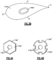
- Each airfoils section 159A extends in a chordwise direction between a leading edge LE and a trailing edge TE, and extends in a thickness direction between a pressure side P and a suction side S, as illustrated by Figure 3B .
- the turbine frame 157 includes a plurality of spokes or tie rods 166 circumferentially distributed between the outer case 162 and the bearing support housing 170.
- Each tie rod 166 includes an elongated body 166A that extends between a first (or radially outer) end portion 166B and a second (or radially inner) end portion 166C.
- the first end portion 166B is coupled to the outer case 162.
- the second end portion 166C is coupled to the bearing support housing 170 to provide a load path directly between the bearing support housing 170 and the outer case 162, which can reduce parts count and overall weight of the engine.
- the turbine frame 157 is free of a separate inner frame case between the tie rods 166 and the bearing support housing 170, which can reduce cost and overall weight and compactness of the engine. Said differently, the bearing support housing 170 provides the function of an inner frame case.
- at least some of the tie rods 166 are one or more of the service lines 68 of Figure 2 .
- each tie rod 166 extends through at least the airfoil section 159A and/or platforms 159B, 159C of a respective one of the vanes 159.
- an inner periphery 162A of the outer case 162 defines a plurality of elongated sockets 162B (one shown) circumferentially distributed about the frame axis B.
- the first end portion 166B of each tie rod 166 is at least partially received in a respective one of the sockets 162B by translating or otherwise moving the tie rod 166 along a first axis X defined by the tie rod 166 or respective socket 162B.
- the first axis X can be oblique to the frame axis B and/or engine axis A of Figure 1 . In other examples, the first axis X is substantially perpendicular to the frame axis B and/or engine axis A.
- the turbine frame 157 includes a plurality of retention members 174 (one shown) for securing the tie rods 166 to the outer case 162.
- Each retention member 174 is slideably received in a respective socket 162B.
- the retention member 174 can be dimensioned to have a relatively close tolerance slip fit relative to the socket 162B, and can be dimensioned to have a relatively long cylindrical contact with walls of the socket 162B to increase stability of the tie rods 166.
- the retention member 174 is moveable relative to the first end portion 166B of the tie rod 166 to cause the first end portion 166B to translate along the first axis X.
- the retention member 174 is an elongated nut that is threadably secured to the first end portion 166B of the tie rod 166.
- the retention member 174 includes threads T1 that engage threads defined by a periphery of the first end portion 166B of the tie rod 166, with the retention member 174 rotatable about the first axis X.
- the tie rod 166 is translatable relative to the socket 162B and along the first axis X in response to rotation of the retention member 174 about the first end portion 166B.
- the turbine frame 157 can also include a plurality of lock rings 176 (one shown). Each lock ring 176 is engageable with a respective retention member 174 to limit rotation of the retention member 174 relative to the outer case 162.
- the lock ring 176 can include a protrusion 176A extending from a plate 176B. The protrusion 176A is received within a bore 174A defined by the retention member 174.
- the protrusion 176A and the bore 174A can have a complementary, non-circular geometry such that the protrusion 176A engages walls of the bore 174A to limit relative rotation.
- protrusion 176A'/176" and bore 174A'/174" define a hexagon or spline interface, as illustrated by Figures 4A and 4B .
- the retention member 174 includes a key 176C that engages a keyway 174B (each shown in dashed lines) defined by the retention member 174 to limit relative rotation.
- the turbine frame 157 can also include one or more plumbing fittings 178 (one shown). Each plumbing fitting 178 defines a fluid plenum FP in communication with a fluid source FS.
- the fluid source FS can be any of the fluid sources disclosed herein, such as coolant source 67 or lubrication source 69 of Figure 2 .
- the lock ring 176 and the plumbing fitting 178 can be mechanically attached to the outer case 162 with one or more fasteners F.
- the tie rod 166 and bearing support housing 170 cooperate to define a locating feature 179 for releasably securing the tie rod 166.
- the locating feature 179 includes the second end portion 166C and a plurality of receptacles 180 (one shown) defined by the bearing support housing 170.
- the receptacles 180 are spaced about an outer periphery 170B of the bearing support housing 170.
- Each of the receptacles 180 can be recessed inwardly relative to the outer periphery 170B of the bearing support housing 170, and at least partially receive the second end portion 166C of a respective one of the tie rods 166.
- the second end portion 166C is seated against surfaces of land 180A of the receptacle 180 to fixedly and releaseably secure the bearing support housing 170 to the outer case 162.
- the arrangement of the second end portion 166C and the receptacles 180 can reduce a complexity of assembling the turbine frame 157 and eliminate the need for fasteners to secure the tie rods 166 to the bearing support housing 170, although one or more fasteners can be utilized to further secure the tie rods 166.
- the second end portion 166C of the tie rod 166 includes one or more engagement surfaces 166D that mate with the receptacle 180.
- the engagement surfaces 166D directly abut against or otherwise directly contact surfaces of a land 180A of the respective receptacle 180 to secure the tie rod 166.
- the land 180A and engagement surfaces 166D limit rotation of the tie rod 166 about the first axis X and with respect to the bearing support housing 170.
- Walls along a perimeter of the land 180A can have a complementary geometry with walls of a perimeter of the second end portion 166C defined by the engagement surfaces 166D, as illustrated schematically by Figure 6 .
- the perimeters of the land 180A and the engagement surfaces 166D can have a substantially non-circular geometry, such as a polygonal geometry. In the illustrated example of Figure 6 , the perimeters of the land 180A and the engagement surfaces 166D have a substantially rectangular geometry to limit or otherwise resist relative rotation.
- the engagement surfaces 166D and the land 180A can included sloped surfaces or bevels for guiding or substantially aligning the second end portion 166C of the tie rod 166 and the receptacle 180 during assembly, with the second end portion 166C wedged in the lands 180A in an assembled position.
- the first axis X can be transverse to the frame axis B and/or engine axis A ( Figure 1 ) to define a first angle ⁇ ( Figure 3A ) such that the sockets 162B are axially offset from the receptacles 180 by a predetermined distance.
- the first angle ⁇ is about 2 to 10 degrees, or about 5 degrees, such that the sockets 162B are axially forward of the receptacles 180 with respect to the frame axis B.
- the first axis X is substantially perpendicular to the frame axis B such that the sockets 162B are substantially axially aligned with the receptacles 180.
- One or more of the receptacles 180 can communicate fluid between the fluid source FS and at least one airflow compartment AC defined by the first and/or second turbines 46, 54 ( Figure 1 ), for example.
- radially inward surfaces 166E of the second end portion 166C are spaced apart from surfaces of the receptacle 180 to define a frame cavity 182.
- the frame cavity 182 can be configured to communicate fluid to the airflow compartment AC via bore 183 defined by an aft flange 170D.
- Aft flange 170D can be simplified and lightened since it is unnecessary for the flange 170D to support bearing loads from the bearing system 138.
- the radially inward surfaces 166E can be sloped relative to an axis that is parallel to the frame axis B to define a second angle ⁇ ( Figure 3A ).
- the second angle ⁇ can be about 2 to 10 degrees, or about 5 degrees, for example, and assists in allowing the second end portions 166C of the tie rods 166 to be guided into the receptacles 180 and to correctly orient the tie rods 166 during assembly.
- the retention members 174 and the tie rods 166 can define a plurality flow paths or fluid passages between the fluid source FS and the frame cavities 182.
- a set of the retention members 174, lock rings 176, and tie rods 166 define respective sections of a flow path or fluid passage 184 between the fluid source FS, outer case 162 and the frame cavity 182.
- the lock ring 176 defines a first fluid passage 176C fluidly coupled to the fluid plenum FP.
- the tie rod 166 defines a second fluid passage 166F coupled to the frame cavity 182.
- the retention member 174 defines a third fluid passage 174C interconnecting the first and second fluid passages 176C and 166F.
- the bearing support housing 170 can define one or more passages 170C (one shown in dashed lines) to communicate fluid between the respective frame cavity 182 and the bearing compartment BC.
- each retention member 174 is at least partially fastened or otherwise mechanically attached to the first end portion 166B of the tie rod 166 via threads T1.
- Each vane 159 is positioned at least partially inside the outer case 162 and can be supported onto the outer case 162 with tooling (not shown).
- Each set of tie rods 166 and retention members 174 is moved generally in a direction D1, such as from a radially inward direction to a radially outward direction, to insert at least a portion of the tie rod 166 through a respective one of the vanes 159 and in a respective one of the sockets 162B.
- the retention member 174 can be secured to the outer case 162 by utilizing a tool bolt TB which can be threadably fastened to the retention member 174 via threads T2, for example.
- the bearing support housing 170 is moved generally in a direction D2 along the frame axis B such that the bearing support housing 170 is at least partially received in the outer case 162. It should be appreciated that the installer can have a line of sight from an axially forward position relative to the frame axis B during movement of the bearing support housing 170, which can also improve the ability to visually inspect the turbine frame 157 during assembly.
- the tool bolt TB can be removed to allow the tie rod 166 and retention member 174 to move a distance inwardly toward the bearing support housing 170.
- the retention member 174 is engaged with tooling, such as a wrench (not shown), to rotate the retention member 174 about the first axis X.
- the retention member 174 is engaged to cause the tie rod 166 to translate or otherwise move along the first axis X in a direction D3 that is generally opposite to direction D1 until the tie rod 166 is located in a desired position.
- the tie rod 166 can be moved in the direction D3 such that the engagement surfaces 166D of the second end portion 166C are brought into direct abutment or contact with surfaces of the land 180A of the receptacle 180, as illustrated by Figures 3A and 5 .
- Walls of the receptacle 180 engage the second end portion 166C to limit rotation of the tie rod 166 relative to the bearing support housing 170. Releasably securing the tie rods 166 to the bearing support housing 170 by preloading the tie rods 166 in compression can reduce assembly complexity and the need for fasteners.
- the retention member 174 can be further rotated by the tooling to cause the tie rod 166 to be preloaded in compression between the outer case 162 and the bearing support housing 170.
- the retention member 174 can be torqued, and the tie rods 166 can be preloaded by a predetermined amount of force that exceeds an expected amount of loading experienced by the tie rods 166 during engine operation, including various maneuvering and compression caused by thermal growth of one or more of the components of the turbine frame 157, such that the tie rods 166 remain in compression during engine operation.
- Thermal expansion of the bearing support housing 170 during engine operation causes the tie rods 166 to remain in compression.
- the predetermined amount of preloading can be defined with respect to the retention members 174 at a location in which the retention member 174 contacts an outer end of the socket 162B, for example, thereby simplifying and improving consistency in the assembly process.
- Figure 9 illustrates a locating feature 279 according to a second example.
- a second end portion 266C of tie rod 266 defines a receptacle 266G.
- the receptacle 266G is dimensioned to receive a protrusion 270E extending from outer periphery 270B of bearing support housing 270 to seat the tie rod 266 against the bearing support housing 270.
- the tie rod 266 can be preloaded in compression utilizing any of the techniques disclosed herein.
Landscapes
- Engineering & Computer Science (AREA)
- Mechanical Engineering (AREA)
- General Engineering & Computer Science (AREA)
- Physics & Mathematics (AREA)
- Fluid Mechanics (AREA)
- Structures Of Non-Positive Displacement Pumps (AREA)
- Turbine Rotor Nozzle Sealing (AREA)
Abstract
coupling a tie rod to the turbine case and to the bearing support housing such that the tie rod is preloaded in compression.
Description
- This disclosure relates to a turbine frame assembly for a gas turbine engine, and more particularly to a turbine frame that supports a bearing.
- A gas turbine engine typically includes a fan section, a compressor section, a combustor section, and a turbine section. Air entering the compressor section is compressed and delivered into the combustion section where it is mixed with fuel and ignited to generate a high-speed exhaust gas flow. The high-speed exhaust gas flow expands through the turbine section to drive the compressor and the fan section. Some turbine engines include a turbine frame in the turbine section that transfers loads between a bearing and other portions of the engine static structure.
- A turbine frame for a gas turbine engine according to an embodiment of the present invention includes a turbine case, a bearing support housing that defines a receptacle, and a tie rod preloaded in compression between the turbine case and the bearing support housing.
- In a further embodiment of the foregoing embodiment, the tie rod includes a first end portion and a second end portion, and the bearing support housing defines a receptacle that at least partially receives the second end portion, with walls of the receptacle that have a complementary geometry with walls of the second end portion.
- In a further embodiment of any of the foregoing embodiments, surfaces of the second end portion are spaced apart from surfaces of the receptacle to define a frame cavity.
- In a further embodiment of any of the foregoing embodiments, the tie rod is a plurality of tie rods. The receptacle is a plurality of receptacles circumferentially distributed about an axis of the bearing support housing. Each of the plurality of tie rods is preloaded in compression between the turbine case and the bearing support housing.
- A further embodiment of any of the foregoing embodiments, includes a retention member moveable relative to the tie rod to compress the tie rod between the turbine case and the receptacle.
- A further embodiment of any of the foregoing embodiments, includes a lock ring engageable with the retention member to limit relative rotation of the turbine case and the tie rod.
- In a further embodiment of any of the foregoing embodiments, the retention member is threadably secured to a first end portion of the tie rod, and is slidably received in a socket defined by the turbine case, with the tie rod translatable relative to the socket in response to rotation of the retention member about the first end portion.
- In a further embodiment of any of the foregoing embodiments, the retention member, the lock ring and the tie rod define respective sections of a flow path between the turbine case and a cavity defined by the receptacle.
- A further embodiment of any of the foregoing embodiments, includes a vane that defines a core flow path, the tie rod extending through the vane.
- A gas turbine engine according to an embodiment of the present invention includes a fan section that has a fan, a compressor section, and a turbine section that drives at least one of the fan section and the compressor section through a shaft. The turbine section has a turbine frame that extends along an engine axis between a first turbine and a second turbine that define a core flow path. The turbine frame includes a bearing support housing that has a bearing that supports the shaft, a turbine case that at least partially surrounds the bearing support housing, and a plurality of tie rods each preloaded in compression between the turbine case and the bearing support housing.
- In a further embodiment of the foregoing embodiment, the bearing support housing defines a plurality of receptacles defined about an outer periphery of the bearing support housing, an inner periphery of the turbine case defines a plurality of sockets, and each of the plurality of tie rods includes a first end portion and a second end portion. The first end portion received in a respective one of the plurality of sockets, and the second end portion seated against surfaces of a respective one of the plurality of receptacles.
- In a further embodiment of any of the foregoing embodiments, each socket of the plurality of sockets is axially offset from a respective receptacle of the plurality of receptacles by a predetermined distance with respect to the engine axis.
- A further embodiment of any of the foregoing embodiments, includes a plurality of retention members each moveable relative to the first end portion of a respective one of the plurality of tie rods to cause the first end portion to translate along a first axis such that the second end portion is brought into direct abutment with surfaces of a respective one of the plurality of receptacles.
- In a further embodiment of any of the foregoing embodiments, each of the plurality of tie rods is translatable along a first axis that is oblique to the engine axis.
- In a further embodiment of any of the foregoing embodiments, the plurality of retention members and the plurality of tie rods define a plurality of flow paths between a fluid source and the plurality of receptacles, and the plurality of receptacles is in fluid communication with at least one airflow compartment defined by one of the first and second turbines.
- A further embodiment of any of the foregoing embodiments, includes a plurality of vanes each having an airfoil section that extend between a first platform and a second platform that bound radially inner and radially outer portions of the core flow path, and each of the plurality of tie rods extending through the airfoil section of a respective one of the plurality of vanes.
- A method of assembling a turbine frame according to an embodiment of the present invention includes moving a bearing support housing at least partially received in a turbine case, and coupling a tie rod to the turbine case and to the bearing support housing such that the tie rod is preloaded in compression.
- A further embodiment of any of the foregoing embodiments, includes positioning a first end portion of the tie rod into a socket defined by an inner periphery of the turbine case; and translating the tie rod along an axis defined by the socket such that a second end portion of the tie rod directly abuts against surfaces of a receptacle defined by an outer periphery of the bearing support housing.
- In a further embodiment of any of the foregoing embodiments, walls of the receptacle engage a perimeter of the second end portion to limit rotation of the tie rod about the axis.
- A further embodiment of any of the foregoing embodiments, includes communicating fluid through a fluid passage defined by the tie rod. The fluid passage interconnects a fluid source and a cavity defined between the second end portion and the receptacle.
- Although the different embodiments have the specific components shown in the illustrations, embodiments of this invention are not limited to those particular combinations. It is possible to use some of the components or features from one of the examples in combination with features or components from another one of the examples.
- The various features and advantages of this invention will become apparent to those skilled in the art from the following detailed description of an embodiment. The drawings that accompany the detailed description can be briefly described as follows.
-
-
Figure 1 shows a gas turbine engine. -
Figure 2 schematically shows a perspective view of a turbine frame according to a first example. -
Figure 3A illustrates a cross-sectional view of a turbine frame according to a second example. -
Figure 3B illustrates a cross-sectional view of an airfoil section taken alongline 3B-3B ofFigure 3A . -
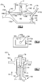
Figure 4 illustrates a portion of the turbine frame ofFigure 3A , including a frame case. -
Figure 4A illustrates a hexagon interface. -
Figure 4B illustrates a spline interface. -
Figure 5 illustrates another portion of the turbine frame ofFigure 3B , including a bearing support housing. -
Figure 6 illustrates a locating feature according to a first example. -
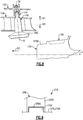
Figure 7 illustrates a portion of the turbine frame ofFigure 3A in a partially assembled position. -
Figure 8 illustrates portions of the turbine frame ofFigure 3A in a partially assembled position. -
Figure 9 illustrates a locating feature according to a second example. -
Figure 1 schematically illustrates agas turbine engine 20. Thegas turbine engine 20 is disclosed herein as a two-spool turbofan that generally incorporates afan section 22, acompressor section 24, acombustor section 26 and aturbine section 28. Alternative engines might include an augmentor section (not shown) among other systems or features. Thefan section 22 drives air along a bypass flow path B in a bypass duct defined within anacelle 15, while thecompressor section 24 drives air along a core flow path C for compression and communication into thecombustor section 26 then expansion through theturbine section 28. Although depicted as a two-spool turbofan gas turbine engine in the disclosed non-limiting embodiment, it should be understood that the concepts described herein are not limited to use with two-spool turbofans as the teachings may be applied to other types of turbine engines including three-spool architectures. - The
exemplary engine 20 generally includes alow speed spool 30 and ahigh speed spool 32 mounted for rotation about an engine central longitudinal axis A relative to an enginestatic structure 36 viaseveral bearing systems 38. It should be understood thatvarious bearing systems 38 at various locations may alternatively or additionally be provided, and the location ofbearing systems 38 may be varied as appropriate to the application. - The
low speed spool 30 generally includes aninner shaft 40 that interconnects afan 42, a first (or low)pressure compressor 44 and a first (or low) pressure turbine 46. Theinner shaft 40 is connected to thefan 42 through a speed change mechanism, which in exemplarygas turbine engine 20 is illustrated as a gearedarchitecture 48 to drive thefan 42 at a lower speed than thelow speed spool 30. Thehigh speed spool 32 includes anouter shaft 50 that interconnects a second (or high)pressure compressor 52 and a second (or high)pressure turbine 54. A combustor 56 is arranged inexemplary gas turbine 20 between thehigh pressure compressor 52 and thehigh pressure turbine 54. Amid-turbine frame 57 of the enginestatic structure 36 is arranged generally between thehigh pressure turbine 54 and the low pressure turbine 46. Themid-turbine frame 57 further supports bearingsystems 38 in theturbine section 28. Theinner shaft 40 and theouter shaft 50 are concentric and rotate viabearing systems 38 about the engine central longitudinal axis A which is collinear with their longitudinal axes. - The core airflow is compressed by the
low pressure compressor 44 then thehigh pressure compressor 52, mixed and burned with fuel in the combustor 56, then expanded over thehigh pressure turbine 54 and low pressure turbine 46. Themid-turbine frame 57 includesairfoils 59 which are in the core airflow path C. Theturbines 46, 54 rotationally drive the respectivelow speed spool 30 andhigh speed spool 32 in response to the expansion. It will be appreciated that each of the positions of thefan section 22,compressor section 24,combustor section 26,turbine section 28, and fandrive gear system 48 may be varied. For example,gear system 48 may be located aft ofcombustor section 26 or even aft ofturbine section 28, andfan section 22 may be positioned forward or aft of the location ofgear system 48. - The
engine 20 in one example is a high-bypass geared aircraft engine. In a further example, theengine 20 bypass ratio is greater than about six, with an example embodiment being greater than about ten, the gearedarchitecture 48 is an epicyclic gear train, such as a planetary gear system or other gear system, with a gear reduction ratio of greater than about 2.3 and the low pressure turbine 46 has a pressure ratio that is greater than about five. In one disclosed embodiment, theengine 20 bypass ratio is greater than about ten, the fan diameter is significantly larger than that of thelow pressure compressor 44, and the low pressure turbine 46 has a pressure ratio that is greater than about five. Low pressure turbine 46 pressure ratio is pressure measured prior to inlet of low pressure turbine 46 as related to the pressure at the outlet of the low pressure turbine 46 prior to an exhaust nozzle. The gearedarchitecture 48 may be an epicycle gear train, such as a planetary gear system or other gear system, with a gear reduction ratio of greater than about 2.3:1. It should be understood, however, that the above parameters are only exemplary of one embodiment of a geared architecture engine and that the present invention is applicable to other gas turbine engines including direct drive turbofans. - A significant amount of thrust is provided by the bypass flow B due to the high bypass ratio. The
fan section 22 of theengine 20 is designed for a particular flight condition -- typically cruise at about 0.8 Mach and about 10,668 m (35,000 feet). The flight condition of 0.8 Mach and 10,668 m (35,000 ft), with the engine at its best fuel consumption - also known as "bucket cruise Thrust Specific Fuel Consumption ('TSFC')" - is the industry standard parameter of lbm of fuel being burned divided by lbf of thrust the engine produces at that minimum point. "Low fan pressure ratio" is the pressure ratio across the fan blade alone, without a Fan Exit Guide Vane ("FEGV") system. The low fan pressure ratio as disclosed herein according to one non-limiting embodiment is less than about 1.45. "Low corrected fan tip speed" is the actual fan tip speed in ft/sec divided by an industry standard temperature correction of [(Tram °R) / (518.7 °R)]0.5 (where °R = K x 9/5). The "Low corrected fan tip speed" as disclosed herein according to one non-limiting embodiment is less than about 351 m/second (1150 ft / second). - The
turbine section 28 can include alternating rows of rotor assemblies and vane assemblies that carry airfoils that extend into the core flow path C. For example, the rotor assemblies can carry a plurality ofrotating blades 25, while each vane assembly can carry a plurality ofvanes 27 that extend into the core flow path C. Thevanes 27 of the vane assemblies direct the core airflow to theblades 25. Theblades 25 extract energy (in the form of pressure) that is communicated through thegas turbine engine 20 along the core flow path C. -
Figure 2 is a schematic perspective view of themid-turbine frame 57. Themid-turbine frame 57 includes anouter frame case 62 and a bearing support member orhousing 70 coaxially arranged about a frame axis B. The frame axis B can be aligned with the engine axis A (Figure 1 ). Themid-turbine frame 57 is arranged axially between the low pressure turbine 46 (or first turbine) and the high pressure turbine 54 (or second turbine) shown inFigure 1 . One or more spokes ortie rods 66 are distributed about thebearing support housing 70 and extend radially between aninner periphery 62A of theouter frame case 62 and anouter periphery 70B of thebearing support housing 70 to provide structural support. For the purposes of this disclosure, the axial and radial directions are in relation to the frame axis B unless stated otherwise. - The bearing
support housing 70 supports the rotor assembly via the bearing system 38 (shown inFigure 1 ) located in a bearing compartment BC, and distributes forces from the bearingsupport housing 70 to theouter frame case 62 via thetie rods 66. Theouter frame case 62 is configured to transfer loads from the bearingsupport housing 70 to other portions of the engine static structure 36 (shown inFigure 1 ). In some examples, one ormore tie rods 66A define cooling passage(s) 55 (shown schematically in dashed line) to communicate cooling airflow from a fluid orcoolant source 67 to thebearing system 38 or to a rotor assembly of theturbine section 28.Coolant sources 67 can include bleed air from an upstream stage of thecompressor section 24, bypass air, or a secondary cooling system aboard the aircraft, for example. - One or
more service lines 68 are distributed around the circumference of thebearing support housing 70 to provide a path between theouter frame case 62 and thebearing support housing 70. In the illustrated example, theservice lines 68 are positioned between adjacent pairs oftie rods 66. Theservice lines 68 can include, but are not limited to, a conduit, a pressurized lubrication oroil supply line 68A, a lubrication oroil scavenge line 68B, acoolant supply line 68C coupled to thecoolant source 67, and a secondary lubrication oroil drain line 68D, for example. - The lubrication supply and scavenge
lines system 38 and alubrication source 69, which can include a reservoir and lubrication pump, for example, such that the bearingsystem 38 is lubricated and cooled during operation of theengine 20. Although sixtie rods 66 and fourservice lines 68 are shown inFigure 2 , more orless tie rods 66 andservice lines 68 can be utilized in view of the teachings herein. In the illustrated example, each of thetie rods 66 andservice lines 68 extends within a respective airfoil orstatic vane 59 arranged in the core flow path C (Figure 1 ). - The
outer frame case 62 defines a plurality ofsockets 62B distributed about the frame axis B. Thetie rods 66 andservice lines 68 together with the bearingsupport housing 70 define a plurality of locating features 79 distributed about the frame case B. The locating features 79 are configured to releasably secure thetie rods 66 andservice lines 68 to thebearing support housing 70. -
Figure 3A illustrates aturbine frame 157, according to an example. In this disclosure, like reference numerals designate like elements where appropriate and reference numerals with the addition of one-hundred or multiples thereof designate modified elements that are understood to incorporate the same features and benefits of the corresponding original elements. Theturbine frame 157 can be incorporated as a mid-turbine frame in theturbine engine 20 between the low pressure (or first) turbine 46 and the high pressure (or second)turbine 54 of theturbine section 28, for example. Other portions of theengine 20 and systems may benefit from the teachings herein, such as thecompressor section 24, turbine exhaust case 47 (Figure 1 ) and adjacent locations of one or more of the bearingsystems 38, land based turbine engines, and fixed wing and rotary aircraft. - The
turbine frame 157 extends along a frame axis B, which may be collinear or parallel with the engine axis A ofFigure 1 . Theturbine frame 157 includes an outer (or turbine)case 162. Theouter case 162 can be coupled to the engine static structure 36 (Figure 1 ), for example. Theouter case 162 extends about the frame axis B to at least partially surround a bearing support member orhousing 170. Aninner periphery 170A of thebearing support housing 170 defines a bearing compartment BC that includes abearing system 138.Bearing system 138 includes at least onebearing 138A that supports ashaft 171. Theshaft 171 can be one of the inner andouter shafts Figure 1 , for example. - The
turbine frame 157 includes a plurality of vanes 159 (one shown) each defining a portion of the core flow path C. Eachvane 159 includes anairfoil section 159A extending between a first (or radially outer)platform 159B and a second (or radially inner)platform 159C. Theplatforms airfoils section 159A extends in a chordwise direction between a leading edge LE and a trailing edge TE, and extends in a thickness direction between a pressure side P and a suction side S, as illustrated byFigure 3B . - The
turbine frame 157 includes a plurality of spokes ortie rods 166 circumferentially distributed between theouter case 162 and thebearing support housing 170. Eachtie rod 166 includes anelongated body 166A that extends between a first (or radially outer)end portion 166B and a second (or radially inner)end portion 166C. Thefirst end portion 166B is coupled to theouter case 162. Thesecond end portion 166C is coupled to thebearing support housing 170 to provide a load path directly between the bearingsupport housing 170 and theouter case 162, which can reduce parts count and overall weight of the engine. In the illustrated example ofFigure 3A , theturbine frame 157 is free of a separate inner frame case between thetie rods 166 and thebearing support housing 170, which can reduce cost and overall weight and compactness of the engine. Said differently, the bearingsupport housing 170 provides the function of an inner frame case. In some examples, at least some of thetie rods 166 are one or more of theservice lines 68 ofFigure 2 . In the illustrated example ofFigure 3A , eachtie rod 166 extends through at least theairfoil section 159A and/orplatforms vanes 159. - Referring to
Figure 4 , with continued reference toFigure 3A , aninner periphery 162A of theouter case 162 defines a plurality ofelongated sockets 162B (one shown) circumferentially distributed about the frame axis B. Thefirst end portion 166B of eachtie rod 166 is at least partially received in a respective one of thesockets 162B by translating or otherwise moving thetie rod 166 along a first axis X defined by thetie rod 166 orrespective socket 162B. The first axis X can be oblique to the frame axis B and/or engine axis A ofFigure 1 . In other examples, the first axis X is substantially perpendicular to the frame axis B and/or engine axis A. - The
turbine frame 157 includes a plurality of retention members 174 (one shown) for securing thetie rods 166 to theouter case 162. Eachretention member 174 is slideably received in arespective socket 162B. Theretention member 174 can be dimensioned to have a relatively close tolerance slip fit relative to thesocket 162B, and can be dimensioned to have a relatively long cylindrical contact with walls of thesocket 162B to increase stability of thetie rods 166. - The
retention member 174 is moveable relative to thefirst end portion 166B of thetie rod 166 to cause thefirst end portion 166B to translate along the first axis X. In the illustrated example ofFigure 4 , theretention member 174 is an elongated nut that is threadably secured to thefirst end portion 166B of thetie rod 166. Theretention member 174 includes threads T1 that engage threads defined by a periphery of thefirst end portion 166B of thetie rod 166, with theretention member 174 rotatable about the first axis X. Thetie rod 166 is translatable relative to thesocket 162B and along the first axis X in response to rotation of theretention member 174 about thefirst end portion 166B. - The
turbine frame 157 can also include a plurality of lock rings 176 (one shown). Eachlock ring 176 is engageable with arespective retention member 174 to limit rotation of theretention member 174 relative to theouter case 162. For example, thelock ring 176 can include aprotrusion 176A extending from aplate 176B. Theprotrusion 176A is received within abore 174A defined by theretention member 174. Theprotrusion 176A and thebore 174A can have a complementary, non-circular geometry such that theprotrusion 176A engages walls of thebore 174A to limit relative rotation. In some examples,protrusion 176A'/176" and bore 174A'/174" define a hexagon or spline interface, as illustrated byFigures 4A and 4B . In other examples, theretention member 174 includes a key 176C that engages akeyway 174B (each shown in dashed lines) defined by theretention member 174 to limit relative rotation. - The
turbine frame 157 can also include one or more plumbing fittings 178 (one shown). Each plumbing fitting 178 defines a fluid plenum FP in communication with a fluid source FS. The fluid source FS can be any of the fluid sources disclosed herein, such ascoolant source 67 orlubrication source 69 ofFigure 2 . Thelock ring 176 and the plumbing fitting 178 can be mechanically attached to theouter case 162 with one or more fasteners F. - Referring to
Figure 5 with continued reference toFigures 3A and4 , thetie rod 166 and bearingsupport housing 170 cooperate to define alocating feature 179 for releasably securing thetie rod 166. The locatingfeature 179 includes thesecond end portion 166C and a plurality of receptacles 180 (one shown) defined by the bearingsupport housing 170. Thereceptacles 180 are spaced about anouter periphery 170B of thebearing support housing 170. Each of thereceptacles 180 can be recessed inwardly relative to theouter periphery 170B of thebearing support housing 170, and at least partially receive thesecond end portion 166C of a respective one of thetie rods 166. - The
second end portion 166C is seated against surfaces ofland 180A of thereceptacle 180 to fixedly and releaseably secure thebearing support housing 170 to theouter case 162. The arrangement of thesecond end portion 166C and thereceptacles 180 can reduce a complexity of assembling theturbine frame 157 and eliminate the need for fasteners to secure thetie rods 166 to thebearing support housing 170, although one or more fasteners can be utilized to further secure thetie rods 166. - The
second end portion 166C of thetie rod 166 includes one ormore engagement surfaces 166D that mate with thereceptacle 180. The engagement surfaces 166D directly abut against or otherwise directly contact surfaces of aland 180A of therespective receptacle 180 to secure thetie rod 166. Theland 180A andengagement surfaces 166D limit rotation of thetie rod 166 about the first axis X and with respect to thebearing support housing 170. - Walls along a perimeter of the
land 180A can have a complementary geometry with walls of a perimeter of thesecond end portion 166C defined by the engagement surfaces 166D, as illustrated schematically byFigure 6 . The perimeters of theland 180A and theengagement surfaces 166D can have a substantially non-circular geometry, such as a polygonal geometry. In the illustrated example ofFigure 6 , the perimeters of theland 180A and theengagement surfaces 166D have a substantially rectangular geometry to limit or otherwise resist relative rotation. The engagement surfaces 166D and theland 180A can included sloped surfaces or bevels for guiding or substantially aligning thesecond end portion 166C of thetie rod 166 and thereceptacle 180 during assembly, with thesecond end portion 166C wedged in thelands 180A in an assembled position. - The first axis X can be transverse to the frame axis B and/or engine axis A (
Figure 1 ) to define a first angle α (Figure 3A ) such that thesockets 162B are axially offset from thereceptacles 180 by a predetermined distance. In some examples, the first angle α is about 2 to 10 degrees, or about 5 degrees, such that thesockets 162B are axially forward of thereceptacles 180 with respect to the frame axis B. In other examples, the first axis X is substantially perpendicular to the frame axis B such that thesockets 162B are substantially axially aligned with thereceptacles 180. - One or more of the
receptacles 180 can communicate fluid between the fluid source FS and at least one airflow compartment AC defined by the first and/or second turbines 46, 54 (Figure 1 ), for example. In the illustrated example ofFigure 5 , radially inward surfaces 166E of thesecond end portion 166C are spaced apart from surfaces of thereceptacle 180 to define aframe cavity 182. Theframe cavity 182 can be configured to communicate fluid to the airflow compartment AC viabore 183 defined by anaft flange 170D.Aft flange 170D can be simplified and lightened since it is unnecessary for theflange 170D to support bearing loads from thebearing system 138. The radiallyinward surfaces 166E can be sloped relative to an axis that is parallel to the frame axis B to define a second angle β (Figure 3A ). The second angle β can be about 2 to 10 degrees, or about 5 degrees, for example, and assists in allowing thesecond end portions 166C of thetie rods 166 to be guided into thereceptacles 180 and to correctly orient thetie rods 166 during assembly. - The
retention members 174 and thetie rods 166 can define a plurality flow paths or fluid passages between the fluid source FS and theframe cavities 182. In the illustrated example ofFigure 4 , a set of theretention members 174, lock rings 176, andtie rods 166 define respective sections of a flow path orfluid passage 184 between the fluid source FS,outer case 162 and theframe cavity 182. Thelock ring 176 defines afirst fluid passage 176C fluidly coupled to the fluid plenum FP. Thetie rod 166 defines asecond fluid passage 166F coupled to theframe cavity 182. Theretention member 174 defines a third fluid passage 174C interconnecting the first and secondfluid passages support housing 170 can define one ormore passages 170C (one shown in dashed lines) to communicate fluid between therespective frame cavity 182 and the bearing compartment BC. - Referring to
Figures 7 and8 , theturbine frame 157 can be assembled as follows. Eachretention member 174 is at least partially fastened or otherwise mechanically attached to thefirst end portion 166B of thetie rod 166 via threads T1. Eachvane 159 is positioned at least partially inside theouter case 162 and can be supported onto theouter case 162 with tooling (not shown). Each set oftie rods 166 andretention members 174 is moved generally in a direction D1, such as from a radially inward direction to a radially outward direction, to insert at least a portion of thetie rod 166 through a respective one of thevanes 159 and in a respective one of thesockets 162B. Theretention member 174 can be secured to theouter case 162 by utilizing a tool bolt TB which can be threadably fastened to theretention member 174 via threads T2, for example. - The bearing
support housing 170 is moved generally in a direction D2 along the frame axis B such that the bearingsupport housing 170 is at least partially received in theouter case 162. It should be appreciated that the installer can have a line of sight from an axially forward position relative to the frame axis B during movement of thebearing support housing 170, which can also improve the ability to visually inspect theturbine frame 157 during assembly. The tool bolt TB can be removed to allow thetie rod 166 andretention member 174 to move a distance inwardly toward the bearingsupport housing 170. - Thereafter, the
retention member 174 is engaged with tooling, such as a wrench (not shown), to rotate theretention member 174 about the first axis X. Theretention member 174 is engaged to cause thetie rod 166 to translate or otherwise move along the first axis X in a direction D3 that is generally opposite to direction D1 until thetie rod 166 is located in a desired position. Thetie rod 166 can be moved in the direction D3 such that the engagement surfaces 166D of thesecond end portion 166C are brought into direct abutment or contact with surfaces of theland 180A of thereceptacle 180, as illustrated byFigures 3A and5 . Walls of thereceptacle 180 engage thesecond end portion 166C to limit rotation of thetie rod 166 relative to thebearing support housing 170. Releasably securing thetie rods 166 to thebearing support housing 170 by preloading thetie rods 166 in compression can reduce assembly complexity and the need for fasteners. - The
retention member 174 can be further rotated by the tooling to cause thetie rod 166 to be preloaded in compression between theouter case 162 and thebearing support housing 170. Theretention member 174 can be torqued, and thetie rods 166 can be preloaded by a predetermined amount of force that exceeds an expected amount of loading experienced by thetie rods 166 during engine operation, including various maneuvering and compression caused by thermal growth of one or more of the components of theturbine frame 157, such that thetie rods 166 remain in compression during engine operation. Thermal expansion of thebearing support housing 170 during engine operation causes thetie rods 166 to remain in compression. The predetermined amount of preloading can be defined with respect to theretention members 174 at a location in which theretention member 174 contacts an outer end of thesocket 162B, for example, thereby simplifying and improving consistency in the assembly process. Once in the installed position, fluid can be communicated through thefluid passage 184 between the fluid source FS and thereceptacle 180. -
Figure 9 illustrates a locatingfeature 279 according to a second example. In the illustrated example, asecond end portion 266C oftie rod 266 defines areceptacle 266G. Thereceptacle 266G is dimensioned to receive aprotrusion 270E extending from outer periphery 270B of bearing support housing 270 to seat thetie rod 266 against the bearing support housing 270. Thetie rod 266 can be preloaded in compression utilizing any of the techniques disclosed herein. - Although particular step sequences are shown, described, and claimed, it should be understood that steps may be performed in any order, separated or combined unless otherwise indicated and will still benefit from the present disclosure.
- It should be understood that relative positional terms such as "forward," "aft," "upper," "lower," "above," "below," and the like are with reference to the normal operational attitude of the vehicle and should not be considered otherwise limiting.
- The foregoing description is exemplary rather than defined by the limitations within. Various non-limiting embodiments are disclosed herein, however, one of ordinary skill in the art would recognize that various modifications and variations in light of the above teachings will fall within the scope of the appended claims. It is therefore to be understood that within the scope of the appended claims, the disclosure may be practiced other than as specifically described. For that reason the appended claims should be studied to determine true scope and content.
Claims (15)
- A turbine frame for a gas turbine engine comprising:a turbine case;a bearing support housing defining a receptacle; andat least one tie rod preloaded in compression between the turbine case and the bearing support housing.
- The turbine frame as recited in claim 1, wherein the at least one tie rod includes a first end portion and a second end portion, and the bearing support housing defines a receptacle that at least partially receives the second end portion, with walls of the receptacle having a complementary geometry with walls of the second end portion, optionally wherein surfaces of the second end portion are spaced apart from surfaces of the receptacle to define a frame cavity.
- The turbine frame as recited in claim 1 or 2, wherein the at least one tie rod comprises a plurality of tie rods, the receptacle comprises a plurality of receptacles circumferentially distributed about an axis of the bearing support housing, and each of the plurality of tie rods is preloaded in compression between the turbine case and the bearing support housing.
- The turbine frame as recited in any preceding claim, comprising a retention member moveable relative to the tie rod to compress the tie rod between the turbine case and the receptacle.
- The turbine frame as recited in claim 4, wherein the retention member is threadably secured to a first end portion of the tie rod, and is slidably received in a socket defined by the turbine case, with the tie rod translatable relative to the socket in response to rotation of the retention member about the first end portion.
- The turbine frame as recited in claim 4 or 5, comprising a lock ring engageable with the retention member to limit relative rotation of the turbine case and the tie rod.
- The turbine frame as recited in claim 6, wherein the retention member, the lock ring and the tie rod define respective sections of a flow path between the turbine case and a cavity defined by the receptacle.
- The turbine frame as recited in any preceding claim, comprising a vane for defining a core flow path of a gas turbine engine, the tie rod extending through the vane.
- A gas turbine engine comprising:a fan section including a fan;a compressor section; anda turbine section driving at least one of the fan section and the compressor section through a shaft, the turbine section including a turbine frame extending along an engine axis between a first turbine and a second turbine that define a core flow path, the turbine frame comprising:a bearing support housing including a bearing that supports the shaft;a turbine case that at least partially surrounds the bearing support housing; anda plurality of tie rods each preloaded in compression between the turbine case and the bearing support housing.
- The gas turbine engine as recited in claim 9, wherein the bearing support housing defines a plurality of receptacles defined about an outer periphery of the bearing support housing, an inner periphery of the turbine case defines a plurality of sockets, and each of the plurality of tie rods includes a first end portion and a second end portion, the first end portion received in a respective one of the plurality of sockets, and the second end portion seated against surfaces of a respective one of the plurality of receptacles, optionally wherein each socket of the plurality of sockets is axially offset from a respective receptacle of the plurality of receptacles by a predetermined distance with respect to the engine axis.
- The gas turbine engine as recited in claim 10, comprising a plurality of retention members each moveable relative to the first end portion of a respective one of the plurality of tie rods to cause the first end portion to translate along a first axis such that the second end portion is brought into direct abutment with surfaces of a respective one of the plurality of receptacles, optionally wherein each of the plurality of tie rods is translatable along the first axis, wherein the first axis oblique to the engine axis.
- The gas turbine engine as recited in claim 11, wherein the plurality of retention members and the plurality of tie rods define a plurality of flow paths between a fluid source and the plurality of receptacles, and the plurality of receptacles are in fluid communication with at least one airflow compartment defined by one of the first and second turbines.
- The gas turbine engine as recited in any of claims 9 to 12, comprising a plurality of vanes each having an airfoil section extending between a first platform and a second platform that bound radially inner and radially outer portions of the core flow path, and each of the plurality of tie rods extends through the airfoil section of a respective one of the plurality of vanes.
- A method of assembling a turbine frame comprising:moving a bearing support housing at least partially received in a turbine case; andcoupling a tie rod to the turbine case and to the bearing support housing such that the tie rod is preloaded in compression.
- The method as recited in claim 14, comprising:positioning a first end portion of the tie rod into a socket defined by an inner periphery of the turbine case; andtranslating the tie rod along an axis defined by the socket such that a second end portion of the tie rod directly abuts against surfaces of a receptacle defined by an outer periphery of the bearing support housing, optionally wherein:walls of the receptacle engage a perimeter of the second end portion to limit rotation of the tie rod about the axis; and/orthe method further comprises communicating fluid through a fluid passage defined by the tie rod, the fluid passage interconnecting a fluid source and a cavity defined between the second end portion and the receptacle.
Applications Claiming Priority (1)
| Application Number | Priority Date | Filing Date | Title |
|---|---|---|---|
| US15/714,005 US10605119B2 (en) | 2017-09-25 | 2017-09-25 | Turbine frame assembly for gas turbine engines |
Publications (2)
| Publication Number | Publication Date |
|---|---|
| EP3460200A1 true EP3460200A1 (en) | 2019-03-27 |
| EP3460200B1 EP3460200B1 (en) | 2023-01-04 |
Family
ID=63685610
Family Applications (1)
| Application Number | Title | Priority Date | Filing Date |
|---|---|---|---|
| EP18196691.2A Active EP3460200B1 (en) | 2017-09-25 | 2018-09-25 | Turbine frame for a gas turbine engine, corresponding gas turbine engine and assembly method a turbine frame |
Country Status (2)
| Country | Link |
|---|---|
| US (1) | US10605119B2 (en) |
| EP (1) | EP3460200B1 (en) |
Cited By (1)
| Publication number | Priority date | Publication date | Assignee | Title |
|---|---|---|---|---|
| FR3142502A1 (en) * | 2022-11-24 | 2024-05-31 | Safran Aircraft Engines | CASING INCLUDING A REINFORCED SEALING SERVICE FOR LUBRICATING THE BEARING SUPPORT OF A TURBOMACHINE CASING |
Families Citing this family (8)
| Publication number | Priority date | Publication date | Assignee | Title |
|---|---|---|---|---|
| US10727656B2 (en) * | 2017-11-08 | 2020-07-28 | Raytheon Technologies Corporation | Igniter cable conduit for gas turbine engine |
| US11230995B2 (en) | 2017-11-08 | 2022-01-25 | Raytheon Technologies Corporation | Cable conduit for turbine engine bypass |
| US11149564B2 (en) * | 2019-06-24 | 2021-10-19 | Rohr, Inc. | Nacelle thrust reverser compression rod supporting system |
| CN110761855B (en) * | 2019-10-11 | 2022-06-07 | 中国航发沈阳发动机研究所 | Gas turbine engine rear casing |
| CN112483190B (en) * | 2020-11-27 | 2022-05-13 | 日照黎阳工业装备有限公司 | Turbine blade based on aeroengine possesses vortex structure |
| CN113356946B (en) * | 2021-07-22 | 2022-08-19 | 中国航发沈阳发动机研究所 | Interturbine casing structure of aircraft engine |
| US12392376B2 (en) * | 2024-01-19 | 2025-08-19 | Pratt & Whitney Canada Corp. | Method of producing a gas turbine engine bearing housing |
| US12486788B1 (en) * | 2024-10-10 | 2025-12-02 | Pratt & Whitney Canada Corp. | Turbine support case supported by stopping ribs |
Citations (4)
| Publication number | Priority date | Publication date | Assignee | Title |
|---|---|---|---|---|
| US3369366A (en) * | 1964-05-28 | 1968-02-20 | Gen Electric | Jet engine support structure |
| WO2014011983A1 (en) * | 2012-07-13 | 2014-01-16 | United Technologies Corporation | Vane insertable tie rods with keyed connections |
| US20160153315A1 (en) * | 2014-12-02 | 2016-06-02 | United Technologies Corporation | Moment accommodating fastener assembly |
| WO2017015745A1 (en) * | 2015-07-24 | 2017-02-02 | Pratt & Whitney Canada Corp. | Spoke mounting arrangement |
Family Cites Families (25)
| Publication number | Priority date | Publication date | Assignee | Title |
|---|---|---|---|---|
| GB695482A (en) * | 1950-11-28 | 1953-08-12 | Rolls Royce | Improvements in or relating to gas-turbine engines |
| US2941848A (en) * | 1955-10-24 | 1960-06-21 | Gen Motors Corp | Spring load bearing support |
| US2919888A (en) | 1957-04-17 | 1960-01-05 | United Aircraft Corp | Turbine bearing support |
| US4183207A (en) * | 1978-03-07 | 1980-01-15 | Avco Corporation | Oil-conducting strut for turbine engines |
| FR2631386A1 (en) | 1988-05-11 | 1989-11-17 | Snecma | TURBOMACHINE HAVING AN INPUT GRID INCORPORATING OIL PIPING TUBES |
| US4987736A (en) * | 1988-12-14 | 1991-01-29 | General Electric Company | Lightweight gas turbine engine frame with free-floating heat shield |
| US4979872A (en) | 1989-06-22 | 1990-12-25 | United Technologies Corporation | Bearing compartment support |
| US5076049A (en) * | 1990-04-02 | 1991-12-31 | General Electric Company | Pretensioned frame |
| US5483792A (en) | 1993-05-05 | 1996-01-16 | General Electric Company | Turbine frame stiffening rails |
| US5746574A (en) * | 1997-05-27 | 1998-05-05 | General Electric Company | Low profile fluid joint |
| ITMI20020910A1 (en) | 2002-04-29 | 2003-10-29 | Nuovo Pignone Spa | SEALING DEVICE FOR COUPLING A PIPE WITH A HOLE |
| US7278516B2 (en) | 2004-03-09 | 2007-10-09 | Honeywell International, Inc. | Apparatus and method for bearing lubrication in turbine engines |
| US7762087B2 (en) | 2006-12-06 | 2010-07-27 | United Technologies Corporation | Rotatable integrated segmented mid-turbine frames |
| US8001791B2 (en) * | 2007-11-13 | 2011-08-23 | United Technologies Corporation | Turbine engine frame having an actuated equilibrating case |
| US8061969B2 (en) | 2008-11-28 | 2011-11-22 | Pratt & Whitney Canada Corp. | Mid turbine frame system for gas turbine engine |
| US8177488B2 (en) * | 2008-11-29 | 2012-05-15 | General Electric Company | Integrated service tube and impingement baffle for a gas turbine engine |
| US20100275572A1 (en) | 2009-04-30 | 2010-11-04 | Pratt & Whitney Canada Corp. | Oil line insulation system for mid turbine frame |
| US9097141B2 (en) | 2011-09-15 | 2015-08-04 | Pratt & Whitney Canada Corp. | Axial bolting arrangement for mid turbine frame |
| US8992173B2 (en) | 2011-11-04 | 2015-03-31 | United Technologies Corporation | Tie-rod nut including a nut flange with a plurality of mounting apertures |
| EP2946083B1 (en) | 2013-01-21 | 2023-07-19 | Raytheon Technologies Corporation | Turbine case adjustment using adjustable tie rods |
| WO2015026600A1 (en) | 2013-08-21 | 2015-02-26 | United Technologies Corporation | Reduced misalignment gear system |
| US10233781B2 (en) | 2014-02-26 | 2019-03-19 | United Technologies Corporation | Tie rod connection for mid-turbine frame |
| US20160201516A1 (en) | 2015-01-09 | 2016-07-14 | United Technologies Corporation | Gas turbine engine mid-turbine frame tie rod arrangement |
| US9920641B2 (en) | 2015-02-23 | 2018-03-20 | United Technologies Corporation | Gas turbine engine mid-turbine frame configuration |
| US20180149085A1 (en) * | 2016-11-28 | 2018-05-31 | General Electric Company | Exhaust frame cooling via cooling flow reversal |
-
2017
- 2017-09-25 US US15/714,005 patent/US10605119B2/en active Active
-
2018
- 2018-09-25 EP EP18196691.2A patent/EP3460200B1/en active Active
Patent Citations (4)
| Publication number | Priority date | Publication date | Assignee | Title |
|---|---|---|---|---|
| US3369366A (en) * | 1964-05-28 | 1968-02-20 | Gen Electric | Jet engine support structure |
| WO2014011983A1 (en) * | 2012-07-13 | 2014-01-16 | United Technologies Corporation | Vane insertable tie rods with keyed connections |
| US20160153315A1 (en) * | 2014-12-02 | 2016-06-02 | United Technologies Corporation | Moment accommodating fastener assembly |
| WO2017015745A1 (en) * | 2015-07-24 | 2017-02-02 | Pratt & Whitney Canada Corp. | Spoke mounting arrangement |
Cited By (1)
| Publication number | Priority date | Publication date | Assignee | Title |
|---|---|---|---|---|
| FR3142502A1 (en) * | 2022-11-24 | 2024-05-31 | Safran Aircraft Engines | CASING INCLUDING A REINFORCED SEALING SERVICE FOR LUBRICATING THE BEARING SUPPORT OF A TURBOMACHINE CASING |
Also Published As
| Publication number | Publication date |
|---|---|
| US20190093507A1 (en) | 2019-03-28 |
| EP3460200B1 (en) | 2023-01-04 |
| US10605119B2 (en) | 2020-03-31 |
Similar Documents
| Publication | Publication Date | Title |
|---|---|---|
| EP3460200B1 (en) | Turbine frame for a gas turbine engine, corresponding gas turbine engine and assembly method a turbine frame | |
| EP3064716B1 (en) | Mid turbine frame with integrated inner case heat shield | |
| EP3095964B1 (en) | Pre-skewed capture plate | |
| US9546560B2 (en) | Compact double grounded mechanical carbon seal | |
| US9988929B2 (en) | Borescope plug for gas turbine engine | |
| EP3034807B1 (en) | Gas turbine engine mid-turbine frame tie rod arrangement | |
| EP3170981A1 (en) | Baffle for a component of a gas turbine engine | |
| WO2015023342A2 (en) | Gas turbine engine with dove-tailed tobi vane | |
| EP2971585B1 (en) | Gas turbine engine turbine vane rail seal | |
| EP3190266B1 (en) | Gas turbine engine comprising a rotor hub seal | |
| EP3103965B1 (en) | Attachment arrangement for turbine engine blade outer air seal | |
| US9765649B2 (en) | Borescope inspection port fitting | |
| CN118815743A (en) | Trunnion-to-disc connection for open fan configuration aircraft powerplant | |
| US9957799B2 (en) | Balance ring for gas turbine engine | |
| EP3260739A1 (en) | Low-cost epicyclic gear carrier and method of making the same | |
| WO2015017040A2 (en) | Gas turbine engine vane ring arrangement | |
| EP3282101B1 (en) | Shim for gas turbine engine | |
| US20140260321A1 (en) | Gas turbine engine static structure joint with undercuts | |
| EP3708778B1 (en) | Inserts for slotted integrally bladed rotor | |
| EP2905427B1 (en) | Gas turbine engine sealing arrangement | |
| EP3564495A1 (en) | Gas turbine engine exhaust component | |
| EP2961964B1 (en) | Gas turbine engine component and corresponding method of manufacturing an aperture | |
| EP2890878B1 (en) | Blade outer air seal | |
| EP3040523A1 (en) | Integrated seal supports | |
| EP3404215B1 (en) | Gas turbine engine with seal anti-rotation lock |
Legal Events
| Date | Code | Title | Description |
|---|---|---|---|
| PUAI | Public reference made under article 153(3) epc to a published international application that has entered the european phase |
Free format text: ORIGINAL CODE: 0009012 |
|
| STAA | Information on the status of an ep patent application or granted ep patent |
Free format text: STATUS: THE APPLICATION HAS BEEN PUBLISHED |
|
| AK | Designated contracting states |
Kind code of ref document: A1 Designated state(s): AL AT BE BG CH CY CZ DE DK EE ES FI FR GB GR HR HU IE IS IT LI LT LU LV MC MK MT NL NO PL PT RO RS SE SI SK SM TR |
|
| AX | Request for extension of the european patent |
Extension state: BA ME |
|
| STAA | Information on the status of an ep patent application or granted ep patent |
Free format text: STATUS: REQUEST FOR EXAMINATION WAS MADE |
|
| 17P | Request for examination filed |
Effective date: 20190927 |
|
| RBV | Designated contracting states (corrected) |
Designated state(s): AL AT BE BG CH CY CZ DE DK EE ES FI FR GB GR HR HU IE IS IT LI LT LU LV MC MK MT NL NO PL PT RO RS SE SI SK SM TR |
|
| STAA | Information on the status of an ep patent application or granted ep patent |
Free format text: STATUS: EXAMINATION IS IN PROGRESS |
|
| 17Q | First examination report despatched |
Effective date: 20200213 |
|
| RAP1 | Party data changed (applicant data changed or rights of an application transferred) |
Owner name: RAYTHEON TECHNOLOGIES CORPORATION |
|
| GRAP | Despatch of communication of intention to grant a patent |
Free format text: ORIGINAL CODE: EPIDOSNIGR1 |
|
| STAA | Information on the status of an ep patent application or granted ep patent |
Free format text: STATUS: GRANT OF PATENT IS INTENDED |
|
| INTG | Intention to grant announced |
Effective date: 20220713 |
|
| GRAS | Grant fee paid |
Free format text: ORIGINAL CODE: EPIDOSNIGR3 |
|
| GRAA | (expected) grant |
Free format text: ORIGINAL CODE: 0009210 |
|
| STAA | Information on the status of an ep patent application or granted ep patent |
Free format text: STATUS: THE PATENT HAS BEEN GRANTED |
|
| AK | Designated contracting states |
Kind code of ref document: B1 Designated state(s): AL AT BE BG CH CY CZ DE DK EE ES FI FR GB GR HR HU IE IS IT LI LT LU LV MC MK MT NL NO PL PT RO RS SE SI SK SM TR |
|
| REG | Reference to a national code |
Ref country code: GB Ref legal event code: FG4D |
|
| REG | Reference to a national code |
Ref country code: CH Ref legal event code: EP |
|
| REG | Reference to a national code |
Ref country code: AT Ref legal event code: REF Ref document number: 1542059 Country of ref document: AT Kind code of ref document: T Effective date: 20230115 |
|
| REG | Reference to a national code |
Ref country code: DE Ref legal event code: R096 Ref document number: 602018044945 Country of ref document: DE |
|
| REG | Reference to a national code |
Ref country code: IE Ref legal event code: FG4D |
|
| REG | Reference to a national code |
Ref country code: LT Ref legal event code: MG9D |
|
| REG | Reference to a national code |
Ref country code: NL Ref legal event code: MP Effective date: 20230104 |
|
| REG | Reference to a national code |
Ref country code: AT Ref legal event code: MK05 Ref document number: 1542059 Country of ref document: AT Kind code of ref document: T Effective date: 20230104 |
|
| P01 | Opt-out of the competence of the unified patent court (upc) registered |
Effective date: 20230521 |
|
| PG25 | Lapsed in a contracting state [announced via postgrant information from national office to epo] |
Ref country code: NL Free format text: LAPSE BECAUSE OF FAILURE TO SUBMIT A TRANSLATION OF THE DESCRIPTION OR TO PAY THE FEE WITHIN THE PRESCRIBED TIME-LIMIT Effective date: 20230104 |
|
| PG25 | Lapsed in a contracting state [announced via postgrant information from national office to epo] |
Ref country code: RS Free format text: LAPSE BECAUSE OF FAILURE TO SUBMIT A TRANSLATION OF THE DESCRIPTION OR TO PAY THE FEE WITHIN THE PRESCRIBED TIME-LIMIT Effective date: 20230104 Ref country code: PT Free format text: LAPSE BECAUSE OF FAILURE TO SUBMIT A TRANSLATION OF THE DESCRIPTION OR TO PAY THE FEE WITHIN THE PRESCRIBED TIME-LIMIT Effective date: 20230504 Ref country code: NO Free format text: LAPSE BECAUSE OF FAILURE TO SUBMIT A TRANSLATION OF THE DESCRIPTION OR TO PAY THE FEE WITHIN THE PRESCRIBED TIME-LIMIT Effective date: 20230404 Ref country code: LV Free format text: LAPSE BECAUSE OF FAILURE TO SUBMIT A TRANSLATION OF THE DESCRIPTION OR TO PAY THE FEE WITHIN THE PRESCRIBED TIME-LIMIT Effective date: 20230104 Ref country code: LT Free format text: LAPSE BECAUSE OF FAILURE TO SUBMIT A TRANSLATION OF THE DESCRIPTION OR TO PAY THE FEE WITHIN THE PRESCRIBED TIME-LIMIT Effective date: 20230104 Ref country code: HR Free format text: LAPSE BECAUSE OF FAILURE TO SUBMIT A TRANSLATION OF THE DESCRIPTION OR TO PAY THE FEE WITHIN THE PRESCRIBED TIME-LIMIT Effective date: 20230104 Ref country code: ES Free format text: LAPSE BECAUSE OF FAILURE TO SUBMIT A TRANSLATION OF THE DESCRIPTION OR TO PAY THE FEE WITHIN THE PRESCRIBED TIME-LIMIT Effective date: 20230104 Ref country code: AT Free format text: LAPSE BECAUSE OF FAILURE TO SUBMIT A TRANSLATION OF THE DESCRIPTION OR TO PAY THE FEE WITHIN THE PRESCRIBED TIME-LIMIT Effective date: 20230104 |
|
| PG25 | Lapsed in a contracting state [announced via postgrant information from national office to epo] |
Ref country code: SE Free format text: LAPSE BECAUSE OF FAILURE TO SUBMIT A TRANSLATION OF THE DESCRIPTION OR TO PAY THE FEE WITHIN THE PRESCRIBED TIME-LIMIT Effective date: 20230104 Ref country code: PL Free format text: LAPSE BECAUSE OF FAILURE TO SUBMIT A TRANSLATION OF THE DESCRIPTION OR TO PAY THE FEE WITHIN THE PRESCRIBED TIME-LIMIT Effective date: 20230104 Ref country code: IS Free format text: LAPSE BECAUSE OF FAILURE TO SUBMIT A TRANSLATION OF THE DESCRIPTION OR TO PAY THE FEE WITHIN THE PRESCRIBED TIME-LIMIT Effective date: 20230504 Ref country code: GR Free format text: LAPSE BECAUSE OF FAILURE TO SUBMIT A TRANSLATION OF THE DESCRIPTION OR TO PAY THE FEE WITHIN THE PRESCRIBED TIME-LIMIT Effective date: 20230405 Ref country code: FI Free format text: LAPSE BECAUSE OF FAILURE TO SUBMIT A TRANSLATION OF THE DESCRIPTION OR TO PAY THE FEE WITHIN THE PRESCRIBED TIME-LIMIT Effective date: 20230104 |
|
| REG | Reference to a national code |
Ref country code: DE Ref legal event code: R097 Ref document number: 602018044945 Country of ref document: DE |
|
| PG25 | Lapsed in a contracting state [announced via postgrant information from national office to epo] |
Ref country code: SM Free format text: LAPSE BECAUSE OF FAILURE TO SUBMIT A TRANSLATION OF THE DESCRIPTION OR TO PAY THE FEE WITHIN THE PRESCRIBED TIME-LIMIT Effective date: 20230104 Ref country code: RO Free format text: LAPSE BECAUSE OF FAILURE TO SUBMIT A TRANSLATION OF THE DESCRIPTION OR TO PAY THE FEE WITHIN THE PRESCRIBED TIME-LIMIT Effective date: 20230104 Ref country code: EE Free format text: LAPSE BECAUSE OF FAILURE TO SUBMIT A TRANSLATION OF THE DESCRIPTION OR TO PAY THE FEE WITHIN THE PRESCRIBED TIME-LIMIT Effective date: 20230104 Ref country code: DK Free format text: LAPSE BECAUSE OF FAILURE TO SUBMIT A TRANSLATION OF THE DESCRIPTION OR TO PAY THE FEE WITHIN THE PRESCRIBED TIME-LIMIT Effective date: 20230104 Ref country code: CZ Free format text: LAPSE BECAUSE OF FAILURE TO SUBMIT A TRANSLATION OF THE DESCRIPTION OR TO PAY THE FEE WITHIN THE PRESCRIBED TIME-LIMIT Effective date: 20230104 |
|
| RAP4 | Party data changed (patent owner data changed or rights of a patent transferred) |
Owner name: RTX CORPORATION |
|
| PLBE | No opposition filed within time limit |
Free format text: ORIGINAL CODE: 0009261 |
|
| STAA | Information on the status of an ep patent application or granted ep patent |
Free format text: STATUS: NO OPPOSITION FILED WITHIN TIME LIMIT |
|
| PG25 | Lapsed in a contracting state [announced via postgrant information from national office to epo] |
Ref country code: SK Free format text: LAPSE BECAUSE OF FAILURE TO SUBMIT A TRANSLATION OF THE DESCRIPTION OR TO PAY THE FEE WITHIN THE PRESCRIBED TIME-LIMIT Effective date: 20230104 |
|
| 26N | No opposition filed |
Effective date: 20231005 |
|
| PG25 | Lapsed in a contracting state [announced via postgrant information from national office to epo] |
Ref country code: SI Free format text: LAPSE BECAUSE OF FAILURE TO SUBMIT A TRANSLATION OF THE DESCRIPTION OR TO PAY THE FEE WITHIN THE PRESCRIBED TIME-LIMIT Effective date: 20230104 |
|
| REG | Reference to a national code |
Ref country code: CH Ref legal event code: PL |
|
| PG25 | Lapsed in a contracting state [announced via postgrant information from national office to epo] |
Ref country code: LU Free format text: LAPSE BECAUSE OF NON-PAYMENT OF DUE FEES Effective date: 20230925 |
|
| REG | Reference to a national code |
Ref country code: BE Ref legal event code: MM Effective date: 20230930 |
|
| PG25 | Lapsed in a contracting state [announced via postgrant information from national office to epo] |
Ref country code: LU Free format text: LAPSE BECAUSE OF NON-PAYMENT OF DUE FEES Effective date: 20230925 Ref country code: IT Free format text: LAPSE BECAUSE OF FAILURE TO SUBMIT A TRANSLATION OF THE DESCRIPTION OR TO PAY THE FEE WITHIN THE PRESCRIBED TIME-LIMIT Effective date: 20230104 Ref country code: MC Free format text: LAPSE BECAUSE OF FAILURE TO SUBMIT A TRANSLATION OF THE DESCRIPTION OR TO PAY THE FEE WITHIN THE PRESCRIBED TIME-LIMIT Effective date: 20230104 |
|
| REG | Reference to a national code |
Ref country code: IE Ref legal event code: MM4A |
|
| PG25 | Lapsed in a contracting state [announced via postgrant information from national office to epo] |
Ref country code: IE Free format text: LAPSE BECAUSE OF NON-PAYMENT OF DUE FEES Effective date: 20230925 |
|
| PG25 | Lapsed in a contracting state [announced via postgrant information from national office to epo] |
Ref country code: CH Free format text: LAPSE BECAUSE OF NON-PAYMENT OF DUE FEES Effective date: 20230930 |
|
| PG25 | Lapsed in a contracting state [announced via postgrant information from national office to epo] |
Ref country code: CH Free format text: LAPSE BECAUSE OF NON-PAYMENT OF DUE FEES Effective date: 20230930 Ref country code: IE Free format text: LAPSE BECAUSE OF NON-PAYMENT OF DUE FEES Effective date: 20230925 |
|
| PG25 | Lapsed in a contracting state [announced via postgrant information from national office to epo] |
Ref country code: BE Free format text: LAPSE BECAUSE OF NON-PAYMENT OF DUE FEES Effective date: 20230930 |
|
| PG25 | Lapsed in a contracting state [announced via postgrant information from national office to epo] |
Ref country code: BG Free format text: LAPSE BECAUSE OF FAILURE TO SUBMIT A TRANSLATION OF THE DESCRIPTION OR TO PAY THE FEE WITHIN THE PRESCRIBED TIME-LIMIT Effective date: 20230104 |
|
| PG25 | Lapsed in a contracting state [announced via postgrant information from national office to epo] |
Ref country code: BG Free format text: LAPSE BECAUSE OF FAILURE TO SUBMIT A TRANSLATION OF THE DESCRIPTION OR TO PAY THE FEE WITHIN THE PRESCRIBED TIME-LIMIT Effective date: 20230104 |
|
| PG25 | Lapsed in a contracting state [announced via postgrant information from national office to epo] |
Ref country code: CY Free format text: LAPSE BECAUSE OF FAILURE TO SUBMIT A TRANSLATION OF THE DESCRIPTION OR TO PAY THE FEE WITHIN THE PRESCRIBED TIME-LIMIT; INVALID AB INITIO Effective date: 20180925 |
|
| PG25 | Lapsed in a contracting state [announced via postgrant information from national office to epo] |
Ref country code: HU Free format text: LAPSE BECAUSE OF FAILURE TO SUBMIT A TRANSLATION OF THE DESCRIPTION OR TO PAY THE FEE WITHIN THE PRESCRIBED TIME-LIMIT; INVALID AB INITIO Effective date: 20180925 |
|
| REG | Reference to a national code |
Ref country code: DE Ref legal event code: R081 Ref document number: 602018044945 Country of ref document: DE Owner name: RTX CORPORATION (N.D.GES.D. STAATES DELAWARE),, US Free format text: FORMER OWNER: RAYTHEON TECHNOLOGIES CORPORATION, FARMINGTON, CT, US |
|
| PGFP | Annual fee paid to national office [announced via postgrant information from national office to epo] |
Ref country code: DE Payment date: 20250820 Year of fee payment: 8 |
|
| PGFP | Annual fee paid to national office [announced via postgrant information from national office to epo] |
Ref country code: GB Payment date: 20250820 Year of fee payment: 8 |
|
| PGFP | Annual fee paid to national office [announced via postgrant information from national office to epo] |
Ref country code: FR Payment date: 20250820 Year of fee payment: 8 |
|
| PG25 | Lapsed in a contracting state [announced via postgrant information from national office to epo] |
Ref country code: TR Free format text: LAPSE BECAUSE OF FAILURE TO SUBMIT A TRANSLATION OF THE DESCRIPTION OR TO PAY THE FEE WITHIN THE PRESCRIBED TIME-LIMIT Effective date: 20230104 |