EP3460164A1 - Insulated door panels - Google Patents
Insulated door panels Download PDFInfo
- Publication number
- EP3460164A1 EP3460164A1 EP18199668.7A EP18199668A EP3460164A1 EP 3460164 A1 EP3460164 A1 EP 3460164A1 EP 18199668 A EP18199668 A EP 18199668A EP 3460164 A1 EP3460164 A1 EP 3460164A1
- Authority
- EP
- European Patent Office
- Prior art keywords
- sheet
- door panel
- water vapor
- thermally insulating
- transmission rate
- Prior art date
- Legal status (The legal status is an assumption and is not a legal conclusion. Google has not performed a legal analysis and makes no representation as to the accuracy of the status listed.)
- Granted
Links
Images





Classifications
-
- E—FIXED CONSTRUCTIONS
- E05—LOCKS; KEYS; WINDOW OR DOOR FITTINGS; SAFES
- E05D—HINGES OR SUSPENSION DEVICES FOR DOORS, WINDOWS OR WINGS
- E05D15/00—Suspension arrangements for wings
- E05D15/16—Suspension arrangements for wings for wings sliding vertically more or less in their own plane
- E05D15/24—Suspension arrangements for wings for wings sliding vertically more or less in their own plane consisting of parts connected at their edges
- E05D15/242—Hinge connections between the parts
-
- E—FIXED CONSTRUCTIONS
- E05—LOCKS; KEYS; WINDOW OR DOOR FITTINGS; SAFES
- E05D—HINGES OR SUSPENSION DEVICES FOR DOORS, WINDOWS OR WINGS
- E05D15/00—Suspension arrangements for wings
- E05D15/16—Suspension arrangements for wings for wings sliding vertically more or less in their own plane
- E05D15/18—Suspension arrangements for wings for wings sliding vertically more or less in their own plane consisting of two or more independent parts, movable each in its own guides
-
- E—FIXED CONSTRUCTIONS
- E05—LOCKS; KEYS; WINDOW OR DOOR FITTINGS; SAFES
- E05F—DEVICES FOR MOVING WINGS INTO OPEN OR CLOSED POSITION; CHECKS FOR WINGS; WING FITTINGS NOT OTHERWISE PROVIDED FOR, CONCERNED WITH THE FUNCTIONING OF THE WING
- E05F15/00—Power-operated mechanisms for wings
- E05F15/60—Power-operated mechanisms for wings using electrical actuators
- E05F15/603—Power-operated mechanisms for wings using electrical actuators using rotary electromotors
- E05F15/665—Power-operated mechanisms for wings using electrical actuators using rotary electromotors for vertically-sliding wings
- E05F15/668—Power-operated mechanisms for wings using electrical actuators using rotary electromotors for vertically-sliding wings for overhead wings
- E05F15/676—Power-operated mechanisms for wings using electrical actuators using rotary electromotors for vertically-sliding wings for overhead wings operated by friction wheels
-
- E—FIXED CONSTRUCTIONS
- E06—DOORS, WINDOWS, SHUTTERS, OR ROLLER BLINDS IN GENERAL; LADDERS
- E06B—FIXED OR MOVABLE CLOSURES FOR OPENINGS IN BUILDINGS, VEHICLES, FENCES OR LIKE ENCLOSURES IN GENERAL, e.g. DOORS, WINDOWS, BLINDS, GATES
- E06B3/00—Window sashes, door leaves, or like elements for closing wall or like openings; Layout of fixed or moving closures, e.g. windows in wall or like openings; Features of rigidly-mounted outer frames relating to the mounting of wing frames
- E06B3/32—Arrangements of wings characterised by the manner of movement; Arrangements of movable wings in openings; Features of wings or frames relating solely to the manner of movement of the wing
- E06B3/34—Arrangements of wings characterised by the manner of movement; Arrangements of movable wings in openings; Features of wings or frames relating solely to the manner of movement of the wing with only one kind of movement
- E06B3/42—Sliding wings; Details of frames with respect to guiding
- E06B3/44—Vertically-sliding wings
-
- E—FIXED CONSTRUCTIONS
- E06—DOORS, WINDOWS, SHUTTERS, OR ROLLER BLINDS IN GENERAL; LADDERS
- E06B—FIXED OR MOVABLE CLOSURES FOR OPENINGS IN BUILDINGS, VEHICLES, FENCES OR LIKE ENCLOSURES IN GENERAL, e.g. DOORS, WINDOWS, BLINDS, GATES
- E06B3/00—Window sashes, door leaves, or like elements for closing wall or like openings; Layout of fixed or moving closures, e.g. windows in wall or like openings; Features of rigidly-mounted outer frames relating to the mounting of wing frames
- E06B3/70—Door leaves
- E06B3/80—Door leaves flexible
-
- E—FIXED CONSTRUCTIONS
- E06—DOORS, WINDOWS, SHUTTERS, OR ROLLER BLINDS IN GENERAL; LADDERS
- E06B—FIXED OR MOVABLE CLOSURES FOR OPENINGS IN BUILDINGS, VEHICLES, FENCES OR LIKE ENCLOSURES IN GENERAL, e.g. DOORS, WINDOWS, BLINDS, GATES
- E06B9/00—Screening or protective devices for wall or similar openings, with or without operating or securing mechanisms; Closures of similar construction
- E06B9/02—Shutters, movable grilles, or other safety closing devices, e.g. against burglary
- E06B9/08—Roll-type closures
- E06B9/11—Roller shutters
- E06B9/13—Roller shutters with closing members of one piece, e.g. of corrugated sheet metal
-
- F—MECHANICAL ENGINEERING; LIGHTING; HEATING; WEAPONS; BLASTING
- F25—REFRIGERATION OR COOLING; COMBINED HEATING AND REFRIGERATION SYSTEMS; HEAT PUMP SYSTEMS; MANUFACTURE OR STORAGE OF ICE; LIQUEFACTION SOLIDIFICATION OF GASES
- F25D—REFRIGERATORS; COLD ROOMS; ICE-BOXES; COOLING OR FREEZING APPARATUS NOT OTHERWISE PROVIDED FOR
- F25D13/00—Stationary devices, e.g. cold-rooms
-
- F—MECHANICAL ENGINEERING; LIGHTING; HEATING; WEAPONS; BLASTING
- F25—REFRIGERATION OR COOLING; COMBINED HEATING AND REFRIGERATION SYSTEMS; HEAT PUMP SYSTEMS; MANUFACTURE OR STORAGE OF ICE; LIQUEFACTION SOLIDIFICATION OF GASES
- F25D—REFRIGERATORS; COLD ROOMS; ICE-BOXES; COOLING OR FREEZING APPARATUS NOT OTHERWISE PROVIDED FOR
- F25D23/00—General constructional features
- F25D23/02—Doors; Covers
- F25D23/021—Sliding doors
-
- E—FIXED CONSTRUCTIONS
- E06—DOORS, WINDOWS, SHUTTERS, OR ROLLER BLINDS IN GENERAL; LADDERS
- E06B—FIXED OR MOVABLE CLOSURES FOR OPENINGS IN BUILDINGS, VEHICLES, FENCES OR LIKE ENCLOSURES IN GENERAL, e.g. DOORS, WINDOWS, BLINDS, GATES
- E06B3/00—Window sashes, door leaves, or like elements for closing wall or like openings; Layout of fixed or moving closures, e.g. windows in wall or like openings; Features of rigidly-mounted outer frames relating to the mounting of wing frames
- E06B3/70—Door leaves
- E06B2003/7049—Specific panel characteristics
- E06B2003/7051—Specific panel characteristics of layered construction involving different materials
-
- E—FIXED CONSTRUCTIONS
- E06—DOORS, WINDOWS, SHUTTERS, OR ROLLER BLINDS IN GENERAL; LADDERS
- E06B—FIXED OR MOVABLE CLOSURES FOR OPENINGS IN BUILDINGS, VEHICLES, FENCES OR LIKE ENCLOSURES IN GENERAL, e.g. DOORS, WINDOWS, BLINDS, GATES
- E06B9/00—Screening or protective devices for wall or similar openings, with or without operating or securing mechanisms; Closures of similar construction
- E06B9/02—Shutters, movable grilles, or other safety closing devices, e.g. against burglary
- E06B9/08—Roll-type closures
- E06B9/11—Roller shutters
- E06B9/17—Parts or details of roller shutters, e.g. suspension devices, shutter boxes, wicket doors, ventilation openings
- E06B2009/17069—Insulation
-
- F—MECHANICAL ENGINEERING; LIGHTING; HEATING; WEAPONS; BLASTING
- F25—REFRIGERATION OR COOLING; COMBINED HEATING AND REFRIGERATION SYSTEMS; HEAT PUMP SYSTEMS; MANUFACTURE OR STORAGE OF ICE; LIQUEFACTION SOLIDIFICATION OF GASES
- F25D—REFRIGERATORS; COLD ROOMS; ICE-BOXES; COOLING OR FREEZING APPARATUS NOT OTHERWISE PROVIDED FOR
- F25D2201/00—Insulation
- F25D2201/10—Insulation with respect to heat
- F25D2201/12—Insulation with respect to heat using an insulating packing material
- F25D2201/126—Insulation with respect to heat using an insulating packing material of cellular type
Definitions
- This patent generally relates to insulated doors and more specifically to doors that comprise a flexible panel such as an insulated curtain.
- Cold storage rooms are refrigerated areas in a building that are commonly used for storing perishable foods. Cold storage rooms are typically large enough for forklifts and other material handling equipment to enter. Access to the room is often through a power actuated insulated door that separates the room from the rest of the building. To minimize thermal losses when someone enters or leaves the room, the door preferably opens and closes as quickly as possible.
- Figures 1 - 4 illustrate an example of a vertically operating door 10 that includes a flexible, insulated door panel 12.
- Door 10 is shown closed in Figure 1 , partially open in Figure 2 , and fully open in Figures 3 and 4 .
- Door panel 12 bends over a mandrel 16.
- Mandrel 16 in some examples, is a fixed bar or a roller extending across the width of doorway 14.
- door panel 12 is shown having a certain double-bend, stored configuration, other stored configurations, such as coiled, wound on a roll tube, single-bend horizontal, serpentine, vertically planar, etc., are all well within the scope of this disclosure.
- door 10 is useful in unlimited applications, door 10 is particularly suited for providing access to refrigerated cold storage rooms or for separating rooms or areas that are at different temperatures, such as, for example, the interior and exterior of a building at a truck loading dock. In such temperature differential installations, one side of door panel 12 is often colder than the other side, which can subject door panel 12 to an adverse water vapor pressure gradient. While Figures 1 - 9 disclose general features of example door panel 12, Figures 10 and 11 disclose more detailed features specifically intended to address the problems associated with the water vapor pressure gradient.
- a powered drive sprocket 18 ( Figure 4 ) engages a cogged strip 20 at each lateral edge of door panel 12 to move door panel 12 between a lower guide track 22, where door panel 12 is blocking doorway 14, and an upper track 24 where door panel 12 is clear of the doorway 14. It should be noted, however, that door panel 12 can be applied to various other types of doors that operate with different drive or storage configurations.
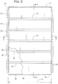
- door panel 12 includes a plurality of pliable baffles 26 ( Figures 5 , 8 and 9 ) that restrict the redistribution of air contained between a first sheet 28 and a second sheet 30 of door panel 12. Sheets 28 and 30 are joined and generally sealed along their outer perimeter to create one large overall air chamber 32 between sheets 28 and 30.
- Baffles 26 divide chamber 32 into a plurality of more manageable smaller chambers 34.
- baffles 26 and chambers 32 and 34 are shown in Figure 5 to extend slightly less than a full width 40 of door panel 12, however, baffles 26 and chambers 32 and 34 preferably extend the full width of door panel 12.
- baffles 26 help prevent air trapped within chamber 32 from over inflating the lower end of door panel 12.
- baffles 26 prevent the area between mandrel 16 and a lower leading edge 36 of door panel 12 from bulging excessively as door 10 opens.
- baffles 26 are sufficiently flexible to accommodate some relative translation between sheets 28 and 30 as door panel 12 bends over mandrel 16. The flexibility of baffles 26 may also enable door panel 12 to restorably break away if something were to accidentally collide with the door 10. Additionally or alternatively, some examples of baffles 26 are sufficiently flexible to conformingly mate with the lateral edges or vertical seams 33 of sheets 28 and 30 so that there is minimal leakage or air exchange between chambers 34. Further, in some examples, baffles 26 are sufficiently stiff to maintain a desired spacing between sheets 28 and 30, particularly in examples where insulation is not used for maintaining such spacing. Further yet, in some examples, baffles 26 have a thermal resistance (i.e., R-value) that is equal to or greater than that of sheets 28 and 30.
- R-value thermal resistance
- sheets 28 and 30 being made of any suitable polymeric or natural fabric material that is preferably pliable and can be joined along their outer perimeter by adhesion, tape, melting/fusing/welding, sewing, hook-and-loop fastener, snaps, rivets, zipper, etc.
- polymeric as used in this patent to describe a material means that the material includes at least some plastic or polymer base, substrate or coating.
- pliable as used in this patent to describe a sheet of material means the sheet is sufficiently flexible to be folded over onto itself and subsequently unfolded without appreciable permanent damage.
- sheets 28 and 30 comprises polyurethane sheet material between about 1 and 2 mm thick (thickness 52).
- substantially the entire outer perimeter, including seams 33 and the upper and lower edges of door panel 12, is sealed to prevent appreciable amounts of air from flowing in and out of chamber 32. Inhibiting moist air from repeatedly entering chamber 32 can prevent mold-promoting water vapor from condensing inside chamber 32 on a panel sheet that is facing, for example, a cold storage room.
- Baffles 26 can be made of a material similar to or different than that of sheets 28 and 30.
- the flexibility of sheets 28 and 30 enables door panel 12 to bend over mandrel 16, while the flexibility of baffles 26 enables limited relative translation between sheets 28 and 30 as door 10 opens and closes. As door 10 opens or closes and door panel 12 travels and bends across mandrel 16, this action urges relative vertical translation between sheets 28 and 30.
- thermally insulating pads 38 e.g., resiliently compressible foam pads, polyester batting, etc.
- the term, "thermally insulating,” as used in this patent to describe pads 38 within door panel 12 means that the pads provide the greatest contribution of the door panel's overall thermal resistance or R-value.
- baffles 26 are horizontally elongate, which enable the baffles 26 to not only restrict vertical airflow within door panel 12 but also to accommodate relative vertical translation between sheets 28 and 30.
- door panel 12 is provided with vertically elongate baffles or a combination of vertical and horizontal baffles.
- baffles 26 preferably extend along at least most of the full width 40 of door panel 12.
- baffles 26 can be made slightly shorter than the panel's full width 40 to make it easier to join the lateral vertical edges of sheets 28 and 30 together.
- Baffles 26 being a little shorter than full width 40 of door panel 12 places the plurality of air chambers 34 in fluid communication with each other.
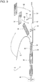
- Figure 9 illustrates one example manufacturing method.
- One horizontal edge of each baffle 26 is melted or ultrasonically welded to first sheet 28, thereby creating a plurality of fused joints 42 between sheet 28 and each of baffles 26.
- Fusing baffles 26 to at least one of sheets 28 and 30 is schematically depicted by the block at reference number 44 of Figure 9 .
- Alternate methods of attaching baffles 26 in place include, but are not limited to, bonding, taping, sewing, fastening via hook-and-loop fastener, riveting, etc.
- An outer perimeter of sheet 28 is fused, sewn or otherwise connected to sheet 30 as schematically depicted by the block at reference number 46 of Figure 9 .
- the plurality of baffles 26 are installed between sheets 28 and 30, as schematically depicted by arrow 48 and insulation pad 38 is installed within chambers 34, as schematically depicted by arrows 50.
- the example method represented by the block at reference number 44 and arrows 48 and 50 may be done generally together in a progressive sequence from one end of door panel 12 to another or in any other suitable order.
- Figure 9 shows door panel 12 being assembled progressively from the bottom up.
- thermally insulating pads 38 is substantially encircled and/or surrounded and preferably encased by a sheet 54 (third sheet) that has a lower water vapor transmission rate than that of polyurethane.
- sheet 54 starts as a tube in which pad 38 is inserted. After pad insertion, the axial ends of the sheet's tubular form are, in some examples, heat sealed to totally encase pad 38 within sheet 54, somewhat analogous to a bed pillow in a pillow case.
- sheet 54 include, but are not limited to, polyester, polyethylene and aluminum foil.
- sheet 54 is between about 0.1 and 0.2 mm thick (thickness 56) with an R-value that is less than that of sheets 28 and 30. Sheet 54 being much thinner than sheets 28 and 30 maximizes the insulating pad's thickness and thus the pad's R-value for a given door panel thickness. Having sheet 54 be relatively thin is a viable option because sheet 54 is protected by the tough outer sheets 28 and 30. While the above example describes the sheet 54 surrounding the pad 38, in other examples, the sheet or sheets 54 may be positioned adjacent one or more surfaces and/or faces of the pad 38.
- the sheet 54 may be positioned adjacent a face of the pad 38 between pad 38 and the sheet 30 (e.g., the sheet to be adjacent a warmer side of the building) while not being adjacent the other faces of the pad 38.
- the sheets 54 may be positioned adjacent opposing surfaces of the pad 38, one of which being positioned between the surface 30 and the pad 38 and the other of which being positioned between the surface 28 and the pad 38.
- baffles 26 lean downward toward the warmer sheet, e.g., toward sheet 30.
- the baffles 26 are at a non-perpendicular angle relative to a longitudinal axis of the panel 12 such that ends of the baffles 22 are longitudinally displaced along the longitudinal axis of the panel 12. This allows baffles 26 to drain any accumulated liquid water within chamber 34 down through optional condensate drain holes 58 in sheet 30.
- Baffle 26 being inclined also allows adjacent pads 38 to overlap at the pads' upper and lower edges, thereby ensuring vertically overlapping insulation at baffles 26.
- a baffle 26' is an alternate example configuration of baffle 26.
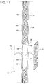
- a sheet 60 (another example third sheet) having a lower water vapor transmission rate than that of polyurethane is installed between pad 38 and sheet 30 to block water vapor on the exterior side of sheet 30 from penetrating chamber 34.
- sheet 60 include, but are not limited to, polyester, polyethylene and aluminum foil.
- sheet 60 is about 0.5 mm thick (thickness 62) with an R-value that is less than that of sheets 28 and 30. The lower R-value of sheet 60, in some examples, is due to sheet 60 being thinner than sheets 28 and 30.
- a continuous or segmented sheet 64 (fourth sheet) is thermally or otherwise joined to sheet 30 and/or baffles 26 to create a plurality of pockets 66 in which sheets 60 are inserted.
- baffles 26 and sheets 28, 30, and 64 each comprise polyurethane.
- An example flexible door panel movable between an open position and a closed position relative to a doorway includes a first pliable sheet made of a first polymeric material.
- the first sheet has a first water vapor transmission rate.
- the example flexible door panel also includes a second pliable sheet made of a second polymeric material.
- the second sheet is generally parallel to the first sheet when the door is in the closed position.
- the second sheet has a second water vapor transmission rate.
- the example flexible door panel also includes a thermally insulating pad between the first sheet and the second sheet.
- the thermally insulating pad is resiliently compressible.
- the example flexible door panel also includes a third sheet between the first sheet and the thermally insulating pad.
- the third sheet has a third water vapor transmission rate.
- the third water vapor transmission rate is lower than the first water vapor transmission rate, and the third water vapor transmission rate is lower than the second water vapor transmission rate.
- the first sheet has a first R-value
- the second sheet has a second R-value
- the third sheet has a third R-value.
- the first R-value is greater than the third R-value
- the second R-value is greater than the third R-value.
- the first sheet has a first thickness
- the second sheet has a second thickness
- the third sheet has a third thickness.
- the first thickness is greater than the third thickness
- the second thickness is greater than the third thickness.
- at least one of the first sheet or the second sheet includes polyurethane.
- at least one of the first sheet or the second sheet defines a condensate drain hole.
- the example flexible door panel also includes a plurality of baffles connecting the first sheet to the second sheet to define a plurality of chambers between the first sheet and the second sheet.
- the plurality of baffles is connected to the first sheet and the second sheet at a plurality of fused joints.
- the example flexible door panel also includes a plurality of thermally insulating pads disposed within the plurality of chambers.
- the plurality of thermally insulating pads includes the thermally insulating pad.
- the third sheet encircles the thermally insulating pad.
- the example flexible door panel also includes a fourth pliable sheet made of a fourth polymeric material.
- the fourth sheet has a fourth water vapor transmission rate that is greater than the third water vapor transmission rate of the third sheet.
- the fourth sheet is joined to at least one of the first sheet or the plurality of baffles to define a pocket between the fourth sheet and the first sheet.
- the third sheet is disposed within the pocket.
- the fourth sheet is interposed between the third sheet and the thermally insulating pad.
- the first sheet is to be colder than the second sheet when the door is installed in the doorway of a cold storage room.
- a flexible door panel movable between an open position and a closed position relative to a doorway includes a first pliable sheet made of a first polymeric material and a second pliable sheet made of a second polymeric material.
- the second sheet is generally parallel to the first sheet when the door is in the closed position.
- the flexible door panel also includes a plurality of baffles connecting the first sheet to the second sheet to define a plurality of chambers between the first sheet and the second sheet.
- the plurality of baffles is connected to the first sheet and the second sheet.
- the flexible door panel also includes a plurality of thermally insulating pads disposed within the plurality of chambers. A thermally insulating pad of the plurality of thermally insulating pads is between the first sheet and the second sheet.
- the thermally insulating pad is resiliently compressible.
- the flexible door panel also includes a third sheet encircling the thermally insulating pad.
- the first sheet has a first R-value
- the second sheet has a second R-value
- the third sheet has a third R-value.
- the first R-value is greater than the third R-value
- the second R-value is greater than the third R-value
- the first sheet has a first thickness
- the second sheet has a second thickness
- the third sheet has a third thickness.
- the first thickness is greater than the third thickness
- the second thickness is greater than the third thickness.
- at least one of the first sheet or the second sheet includes polyurethane.
- at least one of the first sheet or the second sheet defines a condensate drain hole.
- the third sheet has a third water vapor transmission rate. The third water vapor transmission rate is lower than the first water vapor transmission rate, and the third water vapor transmission rate is lower than the second water vapor transmission rate.
- An example flexible door panel movable between an open position and a closed position relative to a doorway includes a first pliable sheet made of a first polymeric material.
- the first sheet has a first water vapor transmission rate.
- the flexible door panel also includes a second pliable sheet made of a second polymeric material.
- the second sheet is generally parallel to the first sheet when the door is in the closed position.
- the second sheet has a second water vapor transmission rate.
- the flexible door panel also includes a plurality of baffles connecting the first sheet to the second sheet to define a plurality of chambers between the first sheet and the second sheet.
- the plurality of baffles is connected to the first sheet and the second sheet.
- the flexible door panel also includes a plurality of thermally insulating pads disposed within the plurality of chambers.
- a thermally insulating pad of the plurality of thermally insulating pads is between the first sheet and the second sheet.
- the thermally insulating pad is resiliently compressible.
- the flexible door panel also includes a third sheet between the first sheet and the thermally insulating pad.
- the third sheet has a third water vapor transmission rate.
- the flexible door panel also includes a fourth pliable sheet made of a fourth polymeric material.
- the fourth sheet is joined to at least one of the first sheet or at least one of the plurality of baffles to define a pocket between the fourth sheet and the first sheet.
- the third sheet is disposed within the pocket.
- the fourth sheet is interposed between the third sheet and the thermally insulating pad.
- the third water vapor transmission rate is lower than the first water vapor transmission rate, and the third water vapor transmission rate is lower than the second water vapor transmission rate.
- the first sheet has a first R-value
- the second sheet has a second R-value
- the third sheet has a third R-value
- the first R-value is greater than the third R-value
- the second R-value is greater than the third R-value.
- the first sheet has a first thickness
- the second sheet has a second thickness
- the third sheet has a third thickness. The first thickness is greater than the third thickness
- the second thickness is greater than the third thickness.
- at least one of the first sheet or the second sheet includes polyurethane.
- at least one of the first sheet or the second sheet defines a condensate drain hole.
- the first sheet is to be colder than the second sheet when the door is installed in the doorway of a cold storage room.
- An example door includes a first sheet coupled to a second sheet to define a chamber therebetween.
- the door also includes a thermally insulating pad within the chamber and a third sheet adjacent the thermally insulating pad to substantially prevent water vapor from permeating the thermally insulating pad.
- the third sheet is positioned between the thermally insulating pad and at least one of first sheet or the second sheet. In some examples, the third sheet substantially surrounds the thermally insulating pad.
- the door may also include a baffle and a drain hole.
- the baffle is coupled to the first and second sheets at a non-perpendicular angle relative to a longitudinal axis of the door when the door is in a closed position.
- the drain hole is defined by one of the first sheet or the second sheet adjacent the baffle to enable liquid to flow within the chamber along at least one of the baffle, the first sheet, or the second sheet through the drain hole.
Landscapes
- Engineering & Computer Science (AREA)
- Structural Engineering (AREA)
- Civil Engineering (AREA)
- Mechanical Engineering (AREA)
- General Engineering & Computer Science (AREA)
- Thermal Sciences (AREA)
- Physics & Mathematics (AREA)
- Combustion & Propulsion (AREA)
- Chemical & Material Sciences (AREA)
- Architecture (AREA)
- Securing Of Glass Panes Or The Like (AREA)
- Laminated Bodies (AREA)
- Refrigerator Housings (AREA)
Abstract
Description
- This patent generally relates to insulated doors and more specifically to doors that comprise a flexible panel such as an insulated curtain.
- Cold storage rooms are refrigerated areas in a building that are commonly used for storing perishable foods. Cold storage rooms are typically large enough for forklifts and other material handling equipment to enter. Access to the room is often through a power actuated insulated door that separates the room from the rest of the building. To minimize thermal losses when someone enters or leaves the room, the door preferably opens and closes as quickly as possible.
- Vertically operating roll-up doors and similar doors with flexible curtains are perhaps some of the fastest operating doors available. When such a door opens, its curtain usually bends upon traveling from its closed position in front of the doorway to its open position on an overhead storage track or take-up roller.
- Such bending is not a problem if the curtain is relatively thin. However, an insulated curtain may not bend as well due to the required thickness of the insulation. When a take-up roller or curved track bends a thick curtain, relative translation may occur between opposite faces of the curtain. Designing a thick, insulated curtain that can accommodate such translation can be challenging.
-
-
Figure 1 is a front view showing an example door in a closed position. -
Figure 2 is a front view similar toFigure 1 but showing the example door partially open. -
Figure 3 is a front view similar toFigures 1 and2 but showing the example door in an open position. -
Figure 4 is a cross-sectional view taken along line 4-4 ofFigure 3 . -
Figure 5 is a front view of the example door panel ofFigures 1 - 3 with a lower-left section of the panel's outer sheet cutaway. -
Figure 6 is a cross-sectional view taken along line 6-6 ofFigure 5 . -
Figure 7 is a cross-sectional view similar toFigure 6 but with the insulation omitted to more clearly show one of the example baffles. -
Figure 8 is a cross-sectional view taken along line 8-8 ofFigure 5 . -
Figure 9 is a cross-sectional view similar toFigure 8 but showing the example door panel being assembled. -
Figure 10 is a cross-sectional view similar toFigure 8 but showing another example assembly and with one pad removed. -
Figure 11 is a cross-sectional view similar toFigure 10 but showing another example assembly. - Certain examples are shown in the above-identified figures and described in detail below. In describing these examples, like or identical reference numbers are used to identify the same or similar elements. The figures are not necessarily to scale and certain features and certain views of the figures may be shown exaggerated in scale or in schematic for clarity and/or conciseness. Additionally, several examples have been described throughout this specification. Any features from any example may be included with, a replacement for, or otherwise combined with other features from other examples.
-
Figures 1 - 4 illustrate an example of a vertically operatingdoor 10 that includes a flexible, insulateddoor panel 12.Door 10 is shown closed inFigure 1 , partially open inFigure 2 , and fully open inFigures 3 and4 . In the illustrated example, asdoor 10 opens and closes relative to adoorway 14,door panel 12 bends over amandrel 16. Mandrel 16, in some examples, is a fixed bar or a roller extending across the width ofdoorway 14. Althoughdoor panel 12 is shown having a certain double-bend, stored configuration, other stored configurations, such as coiled, wound on a roll tube, single-bend horizontal, serpentine, vertically planar, etc., are all well within the scope of this disclosure. - Although
door 10 is useful in unlimited applications,door 10 is particularly suited for providing access to refrigerated cold storage rooms or for separating rooms or areas that are at different temperatures, such as, for example, the interior and exterior of a building at a truck loading dock. In such temperature differential installations, one side ofdoor panel 12 is often colder than the other side, which can subjectdoor panel 12 to an adverse water vapor pressure gradient. WhileFigures 1 - 9 disclose general features ofexample door panel 12,Figures 10 and11 disclose more detailed features specifically intended to address the problems associated with the water vapor pressure gradient. - To operate
door 10, in some examples, a powered drive sprocket 18 (Figure 4 ) engages acogged strip 20 at each lateral edge ofdoor panel 12 to movedoor panel 12 between alower guide track 22, wheredoor panel 12 is blockingdoorway 14, and anupper track 24 wheredoor panel 12 is clear of thedoorway 14. It should be noted, however, thatdoor panel 12 can be applied to various other types of doors that operate with different drive or storage configurations. - In some examples,
door panel 12 includes a plurality of pliable baffles 26 (Figures 5 ,8 and9 ) that restrict the redistribution of air contained between afirst sheet 28 and asecond sheet 30 ofdoor panel 12.Sheets overall air chamber 32 betweensheets chamber 32 into a plurality of more manageablesmaller chambers 34. For illustrative clarity,baffles 26 andchambers Figure 5 to extend slightly less than afull width 40 ofdoor panel 12, however,baffles 26 andchambers door panel 12. Asdoor 10 opens and creates a horizontal crease insheets 28 and 30 (e.g., wheredoor panel 12 bends over mandrel 16),baffles 26 help prevent air trapped withinchamber 32 from over inflating the lower end ofdoor panel 12. Thus,baffles 26 prevent the area betweenmandrel 16 and a lower leadingedge 36 ofdoor panel 12 from bulging excessively asdoor 10 opens. - In some examples,
baffles 26 are sufficiently flexible to accommodate some relative translation betweensheets door panel 12 bends overmandrel 16. The flexibility ofbaffles 26 may also enabledoor panel 12 to restorably break away if something were to accidentally collide with thedoor 10. Additionally or alternatively, some examples ofbaffles 26 are sufficiently flexible to conformingly mate with the lateral edges orvertical seams 33 ofsheets chambers 34. Further, in some examples,baffles 26 are sufficiently stiff to maintain a desired spacing betweensheets baffles 26 have a thermal resistance (i.e., R-value) that is equal to or greater than that ofsheets - Although the actual construction of
door panel 12 may vary, the illustrated examples havesheets sheets seams 33 and the upper and lower edges ofdoor panel 12, is sealed to prevent appreciable amounts of air from flowing in and out ofchamber 32. Inhibiting moist air from repeatedly enteringchamber 32 can prevent mold-promoting water vapor from condensing insidechamber 32 on a panel sheet that is facing, for example, a cold storage room. -
Baffles 26 can be made of a material similar to or different than that ofsheets sheets door panel 12 to bend overmandrel 16, while the flexibility ofbaffles 26 enables limited relative translation betweensheets door 10 opens and closes. Asdoor 10 opens or closes anddoor panel 12 travels and bends acrossmandrel 16, this action urges relative vertical translation betweensheets chambers 34. The term, "thermally insulating," as used in this patent to describepads 38 withindoor panel 12 means that the pads provide the greatest contribution of the door panel's overall thermal resistance or R-value. - For the illustrated examples,
baffles 26 are horizontally elongate, which enable thebaffles 26 to not only restrict vertical airflow withindoor panel 12 but also to accommodate relative vertical translation betweensheets door panel 12 is provided with vertically elongate baffles or a combination of vertical and horizontal baffles. - To effectively restrict airflow within
door panel 12, horizontally elongate baffles 26 preferably extend along at least most of thefull width 40 ofdoor panel 12. To facilitate manufacturing, however, baffles 26 can be made slightly shorter than the panel'sfull width 40 to make it easier to join the lateral vertical edges ofsheets full width 40 ofdoor panel 12 places the plurality ofair chambers 34 in fluid communication with each other. Thus, asdoor 10 opens anddoor panel 12 travels acrossmandrel 16, some air withindoor panel 12 will be temporarily redistributed to at least one of the lower chambers (e.g., air chamber 34') of the plurality ofchambers 34, thereby slightly increasing the air pressure within chamber 34' temporarily, but not really detrimentally. - Although the general assembly of
door panel 12 can be accomplished by various means,Figure 9 illustrates one example manufacturing method. One horizontal edge of eachbaffle 26 is melted or ultrasonically welded tofirst sheet 28, thereby creating a plurality of fusedjoints 42 betweensheet 28 and each ofbaffles 26. Fusing baffles 26 to at least one ofsheets reference number 44 ofFigure 9 . Alternate methods of attachingbaffles 26 in place include, but are not limited to, bonding, taping, sewing, fastening via hook-and-loop fastener, riveting, etc. - An outer perimeter of
sheet 28 is fused, sewn or otherwise connected tosheet 30 as schematically depicted by the block atreference number 46 ofFigure 9 . The plurality ofbaffles 26 are installed betweensheets arrow 48 andinsulation pad 38 is installed withinchambers 34, as schematically depicted byarrows 50. The example method represented by the block atreference number 44 andarrows door panel 12 to another or in any other suitable order.Figure 9 , for example, showsdoor panel 12 being assembled progressively from the bottom up. -
Sheets sheets pads 38 toward thecolder sheet sheet 30, for example, is warmer thansheet 28, water vapor might permeatedoor panel 12 throughsheet 30 and condense and perhaps freeze on the inner surface ofsheet 28. An accumulation of trapped liquid water or ice withinchamber 34 may inhibit normal operating characteristics of thedoor panel 12. - To address this potential problem, thermally insulating
pads 38, as shown in the example ofFigure 10 , is substantially encircled and/or surrounded and preferably encased by a sheet 54 (third sheet) that has a lower water vapor transmission rate than that of polyurethane. In some examples,sheet 54 starts as a tube in whichpad 38 is inserted. After pad insertion, the axial ends of the sheet's tubular form are, in some examples, heat sealed to totally encasepad 38 withinsheet 54, somewhat analogous to a bed pillow in a pillow case. Examples ofsheet 54 include, but are not limited to, polyester, polyethylene and aluminum foil. In some examples,sheet 54 is between about 0.1 and 0.2 mm thick (thickness 56) with an R-value that is less than that ofsheets Sheet 54 being much thinner thansheets sheet 54 be relatively thin is a viable option becausesheet 54 is protected by the toughouter sheets sheet 54 surrounding thepad 38, in other examples, the sheet orsheets 54 may be positioned adjacent one or more surfaces and/or faces of thepad 38. For example, thesheet 54 may be positioned adjacent a face of thepad 38 betweenpad 38 and the sheet 30 (e.g., the sheet to be adjacent a warmer side of the building) while not being adjacent the other faces of thepad 38. In other examples, thesheets 54 may be positioned adjacent opposing surfaces of thepad 38, one of which being positioned between thesurface 30 and thepad 38 and the other of which being positioned between thesurface 28 and thepad 38. - In addition or alternatively, in some examples, baffles 26 lean downward toward the warmer sheet, e.g., toward
sheet 30. In the illustrated example, thebaffles 26 are at a non-perpendicular angle relative to a longitudinal axis of thepanel 12 such that ends of thebaffles 22 are longitudinally displaced along the longitudinal axis of thepanel 12. This allows baffles 26 to drain any accumulated liquid water withinchamber 34 down through optional condensate drain holes 58 insheet 30.Baffle 26 being inclined also allowsadjacent pads 38 to overlap at the pads' upper and lower edges, thereby ensuring vertically overlapping insulation at baffles 26. A baffle 26' is an alternate example configuration ofbaffle 26. - In addition or alternatively, as shown in
Figure 11 , a sheet 60 (another example third sheet) having a lower water vapor transmission rate than that of polyurethane is installed betweenpad 38 andsheet 30 to block water vapor on the exterior side ofsheet 30 from penetratingchamber 34. Examples ofsheet 60 include, but are not limited to, polyester, polyethylene and aluminum foil. In some examples,sheet 60 is about 0.5 mm thick (thickness 62) with an R-value that is less than that ofsheets sheet 60, in some examples, is due tosheet 60 being thinner thansheets - To help hold
multiple sheets 60 in place, in some examples, a continuous or segmented sheet 64 (fourth sheet) is thermally or otherwise joined tosheet 30 and/or baffles 26 to create a plurality ofpockets 66 in whichsheets 60 are inserted. To facilitate effective thermal bonding ofsheet 64 withsheet 30 and/or baffle 26, in some examples, baffles 26 andsheets - An example flexible door panel movable between an open position and a closed position relative to a doorway includes a first pliable sheet made of a first polymeric material. The first sheet has a first water vapor transmission rate. The example flexible door panel also includes a second pliable sheet made of a second polymeric material. The second sheet is generally parallel to the first sheet when the door is in the closed position. The second sheet has a second water vapor transmission rate. The example flexible door panel also includes a thermally insulating pad between the first sheet and the second sheet. The thermally insulating pad is resiliently compressible. The example flexible door panel also includes a third sheet between the first sheet and the thermally insulating pad. The third sheet has a third water vapor transmission rate. The third water vapor transmission rate is lower than the first water vapor transmission rate, and the third water vapor transmission rate is lower than the second water vapor transmission rate.
- In some examples, the first sheet has a first R-value, the second sheet has a second R-value, and the third sheet has a third R-value. The first R-value is greater than the third R-value, and the second R-value is greater than the third R-value. In some examples, the first sheet has a first thickness, the second sheet has a second thickness, the third sheet has a third thickness. The first thickness is greater than the third thickness, and the second thickness is greater than the third thickness. In some examples, at least one of the first sheet or the second sheet includes polyurethane. In some examples, at least one of the first sheet or the second sheet defines a condensate drain hole.
- In some examples, the example flexible door panel also includes a plurality of baffles connecting the first sheet to the second sheet to define a plurality of chambers between the first sheet and the second sheet. The plurality of baffles is connected to the first sheet and the second sheet at a plurality of fused joints. In some examples, the example flexible door panel also includes a plurality of thermally insulating pads disposed within the plurality of chambers. The plurality of thermally insulating pads includes the thermally insulating pad. In some examples, the third sheet encircles the thermally insulating pad. In some examples, the example flexible door panel also includes a fourth pliable sheet made of a fourth polymeric material. The fourth sheet has a fourth water vapor transmission rate that is greater than the third water vapor transmission rate of the third sheet. The fourth sheet is joined to at least one of the first sheet or the plurality of baffles to define a pocket between the fourth sheet and the first sheet. The third sheet is disposed within the pocket. The fourth sheet is interposed between the third sheet and the thermally insulating pad. In some examples, the first sheet is to be colder than the second sheet when the door is installed in the doorway of a cold storage room.
- In some examples, a flexible door panel movable between an open position and a closed position relative to a doorway includes a first pliable sheet made of a first polymeric material and a second pliable sheet made of a second polymeric material. The second sheet is generally parallel to the first sheet when the door is in the closed position. The flexible door panel also includes a plurality of baffles connecting the first sheet to the second sheet to define a plurality of chambers between the first sheet and the second sheet. The plurality of baffles is connected to the first sheet and the second sheet. The flexible door panel also includes a plurality of thermally insulating pads disposed within the plurality of chambers. A thermally insulating pad of the plurality of thermally insulating pads is between the first sheet and the second sheet. The thermally insulating pad is resiliently compressible. The flexible door panel also includes a third sheet encircling the thermally insulating pad.
- In some examples, the first sheet has a first R-value, the second sheet has a second R-value, the third sheet has a third R-value. The first R-value is greater than the third R-value, and and the second R-value is greater than the third R-value. In some examples, the first sheet has a first thickness, the second sheet has a second thickness, the third sheet has a third thickness. The first thickness is greater than the third thickness, and the second thickness is greater than the third thickness. In some examples, at least one of the first sheet or the second sheet includes polyurethane. In some examples, at least one of the first sheet or the second sheet defines a condensate drain hole. In some examples, the third sheet has a third water vapor transmission rate. The third water vapor transmission rate is lower than the first water vapor transmission rate, and the third water vapor transmission rate is lower than the second water vapor transmission rate.
- An example flexible door panel movable between an open position and a closed position relative to a doorway includes a first pliable sheet made of a first polymeric material. The first sheet has a first water vapor transmission rate. The flexible door panel also includes a second pliable sheet made of a second polymeric material. The second sheet is generally parallel to the first sheet when the door is in the closed position. The second sheet has a second water vapor transmission rate. The flexible door panel also includes a plurality of baffles connecting the first sheet to the second sheet to define a plurality of chambers between the first sheet and the second sheet. The plurality of baffles is connected to the first sheet and the second sheet. The flexible door panel also includes a plurality of thermally insulating pads disposed within the plurality of chambers. A thermally insulating pad of the plurality of thermally insulating pads is between the first sheet and the second sheet. The thermally insulating pad is resiliently compressible. The flexible door panel also includes a third sheet between the first sheet and the thermally insulating pad. The third sheet has a third water vapor transmission rate. The flexible door panel also includes a fourth pliable sheet made of a fourth polymeric material. The fourth sheet is joined to at least one of the first sheet or at least one of the plurality of baffles to define a pocket between the fourth sheet and the first sheet. The third sheet is disposed within the pocket. The fourth sheet is interposed between the third sheet and the thermally insulating pad. The third water vapor transmission rate is lower than the first water vapor transmission rate, and the third water vapor transmission rate is lower than the second water vapor transmission rate.
- In some examples, the first sheet has a first R-value, the second sheet has a second R-value, the third sheet has a third R-value, the first R-value is greater than the third R-value, and the second R-value is greater than the third R-value. In some examples, the first sheet has a first thickness, the second sheet has a second thickness, the third sheet has a third thickness. The first thickness is greater than the third thickness, and the second thickness is greater than the third thickness. In some examples, at least one of the first sheet or the second sheet includes polyurethane. In some examples, at least one of the first sheet or the second sheet defines a condensate drain hole. In some examples, the first sheet is to be colder than the second sheet when the door is installed in the doorway of a cold storage room.
- An example door includes a first sheet coupled to a second sheet to define a chamber therebetween. The door also includes a thermally insulating pad within the chamber and a third sheet adjacent the thermally insulating pad to substantially prevent water vapor from permeating the thermally insulating pad. The third sheet is positioned between the thermally insulating pad and at least one of first sheet or the second sheet. In some examples, the third sheet substantially surrounds the thermally insulating pad. The door may also include a baffle and a drain hole. The baffle is coupled to the first and second sheets at a non-perpendicular angle relative to a longitudinal axis of the door when the door is in a closed position. The drain hole is defined by one of the first sheet or the second sheet adjacent the baffle to enable liquid to flow within the chamber along at least one of the baffle, the first sheet, or the second sheet through the drain hole.
- Although certain example methods, apparatus and articles of manufacture have been described herein, the scope of the coverage of this patent is not limited thereto. On the contrary, this patent covers all methods, apparatus and articles of manufacture fairly falling within the scope of the appended claims either literally or under the doctrine of equivalents.
Claims (10)
- A flexible door panel movable between an open position and a closed position relative to a doorway, the door panel comprising:a first pliable sheet (28) made of a first polymeric material, the first sheet (28) having a first water vapor transmission rate;a second pliable sheet (30) made of a second polymeric material, the second sheet (30) being generally parallel to the first sheet (28) when the door is in the closed position, the second sheet (30) having a second water vapor transmission rate;a thermally insulating pad (38) between the first sheet (28) and the second sheet (30), the thermally insulating pad (38) being resiliently compressible; anda third sheet (60) between the first sheet (28) and the thermally insulating pad (38), the third sheet (60) having a third water vapor transmission rate, the third water vapor transmission rate being lower than the first water vapor transmission rate, and the third water vapor transmission rate being lower than the second water vapor transmission rate.
- The flexible door panel of claim 1, wherein the first sheet (28) has a first R-value, the second sheet (30) has a second R-value, the third sheet (60) has a third R-value, the first R-value is greater than the third R-value, and the second R-value is greater than the third R-value.
- The flexible door panel of claim 1, wherein the first sheet (28) has a first thickness, the second sheet (30) has a second thickness, the third sheet (60) has a third thickness, the first thickness is greater than the third thickness, and the second thickness is greater than the third thickness.
- The flexible door panel of claim 1, wherein at least one of the first sheet (28) or the second sheet (30) comprises polyurethane.
- The flexible door panel of claim 1, wherein at least one of the first sheet (28) or the second sheet (30) defines a condensate drain hole.
- The flexible door panel of claim 1 further comprising:a plurality of baffles (26) connecting the first sheet (28) to the second sheet (30) to define a plurality of chambers between the first sheet (28) and the second sheet (30), the plurality of baffles (26) being connected to the first sheet (28) and the second sheet (30) at a plurality of fused joints; anda plurality of thermally insulating pads disposed within the plurality of chambers, the plurality of thermally insulating pad (38) includes the thermally insulating pad (38).
- The flexible door panel of claim 6, further comprising a fourth pliable sheet (64) made of a fourth polymeric material, the fourth sheet (64) having a fourth water vapor transmission rate that is greater than the third water vapor transmission rate of the third sheet (60), the fourth sheet (64) being joined to at least one of the first sheet (28) or the plurality of baffles (26) to define a pocket between the fourth sheet (64) and the first sheet (28), the third sheet (60) being disposed within the pocket, the fourth sheet (64) being interposed between the third sheet (60) and the thermally insulating pad (38).
- The flexible door panel of claim 1, wherein the first sheet (28) is to be colder than the second sheet (30) when the door is installed in the doorway of a cold storage room.
- The flexible door panel of claim 1, wherein the third sheet (60) is adjacent the thermally insulating pad (38) to substantially prevent water vapor from permeating the thermally insulating pad (38), the third sheet (60) being positioned between the thermally insulating pad (38) and at least one of first sheet (28) or the second sheet (30).
- The door of claim 9, further comprising a baffle (26) and a drain hole, the baffle (26) coupled to the first and second sheets at a non-perpendicular angle relative to a longitudinal axis of the door when the door is in a closed position, the drain hole defined by one of the first sheet (28) or the second sheet (30) adjacent the baffle (26) to enable liquid to flow within the chamber along at least one of the baffle (26), the first sheet (28), or the second sheet (30) through the drain hole.
Applications Claiming Priority (3)
| Application Number | Priority Date | Filing Date | Title |
|---|---|---|---|
| US13/532,379 US9410363B2 (en) | 2012-06-25 | 2012-06-25 | Insulated door panels |
| PCT/US2013/047365 WO2014004390A1 (en) | 2012-06-25 | 2013-06-24 | Insulated door panels |
| EP13734278.8A EP2864568B1 (en) | 2012-06-25 | 2013-06-24 | Insulated door panels |
Related Parent Applications (2)
| Application Number | Title | Priority Date | Filing Date |
|---|---|---|---|
| EP13734278.8A Division-Into EP2864568B1 (en) | 2012-06-25 | 2013-06-24 | Insulated door panels |
| EP13734278.8A Division EP2864568B1 (en) | 2012-06-25 | 2013-06-24 | Insulated door panels |
Publications (2)
| Publication Number | Publication Date |
|---|---|
| EP3460164A1 true EP3460164A1 (en) | 2019-03-27 |
| EP3460164B1 EP3460164B1 (en) | 2025-06-18 |
Family
ID=48746696
Family Applications (2)
| Application Number | Title | Priority Date | Filing Date |
|---|---|---|---|
| EP18199668.7A Active EP3460164B1 (en) | 2012-06-25 | 2013-06-24 | Insulated door panels |
| EP13734278.8A Active EP2864568B1 (en) | 2012-06-25 | 2013-06-24 | Insulated door panels |
Family Applications After (1)
| Application Number | Title | Priority Date | Filing Date |
|---|---|---|---|
| EP13734278.8A Active EP2864568B1 (en) | 2012-06-25 | 2013-06-24 | Insulated door panels |
Country Status (4)
| Country | Link |
|---|---|
| US (2) | US9410363B2 (en) |
| EP (2) | EP3460164B1 (en) |
| ES (2) | ES3040759T3 (en) |
| WO (1) | WO2014004390A1 (en) |
Families Citing this family (18)
| Publication number | Priority date | Publication date | Assignee | Title |
|---|---|---|---|---|
| NL1038868C2 (en) * | 2011-06-10 | 2012-12-11 | Cornelis Elizabeth Rijlaarsdam | WATER FENCE FOR A TRANSITION. |
| US9151084B2 (en) * | 2011-08-15 | 2015-10-06 | Cold Chain, Llc | Insulated overhead door |
| US9410363B2 (en) | 2012-06-25 | 2016-08-09 | Rite-Hite Holding Corporation | Insulated door panels |
| DE202013005164U1 (en) * | 2013-06-06 | 2013-07-30 | Seuster Kg | gate |
| US20150020617A1 (en) * | 2013-07-19 | 2015-01-22 | Rodney H. Neumann | Sprocket-Driven Door |
| US10773881B2 (en) * | 2015-10-05 | 2020-09-15 | Advanced Composite Structures, Llc | Air cargo container and curtain for the same |
| US11851270B2 (en) | 2017-10-10 | 2023-12-26 | Advanced Composite Structures, Llc | Latch for air cargo container doors |
| CN108071896B (en) * | 2017-10-20 | 2020-01-31 | 武汉船用机械有限责任公司 | crane heat preservation system |
| KR101822577B1 (en) * | 2017-10-31 | 2018-03-08 | 나정균 | Eco-friendly ice pack |
| US10487570B1 (en) | 2018-07-05 | 2019-11-26 | Schlage Lock Company Llc | Door with interior protective coating |
| EP3887636B1 (en) | 2018-11-30 | 2025-07-02 | Rytec Corporation | Door assembly with two drive sprockets and two corresponding drive guides |
| GB2580673B (en) * | 2019-01-22 | 2026-03-25 | Insu Flex Ltd | Improvements relating to insulated doors |
| US10822807B2 (en) * | 2019-02-18 | 2020-11-03 | Royal Building Products (Usa) Inc. | Assembly for improved insulation |
| EP3990271A4 (en) | 2019-06-28 | 2022-12-28 | Advanced Composite Structures, LLC | Thermally insulated air cargo container |
| US12048856B2 (en) * | 2020-05-19 | 2024-07-30 | Mckeon Rolling Steel Door Co., Inc. | Multi layer fire curtain |
| GB2603134B (en) * | 2021-01-27 | 2025-04-09 | Clark Door Ltd | Door Assembly |
| US12091239B2 (en) | 2021-11-11 | 2024-09-17 | Advanced Composite Structures, Llc | Formed structural panel with open core |
| EP4372196A1 (en) * | 2022-11-17 | 2024-05-22 | Frinova GmbH | Quick-running door |
Citations (6)
| Publication number | Priority date | Publication date | Assignee | Title |
|---|---|---|---|---|
| WO1990009281A1 (en) * | 1989-02-17 | 1990-08-23 | Courtaulds Plc | Flexible fabric thermal insulators |
| EP1559449A1 (en) * | 2004-01-27 | 2005-08-03 | Goldfire Sprl | Flexible wall having fire resistant properties |
| DE202005012486U1 (en) * | 2005-08-09 | 2005-10-27 | Swl Tischlerplatten Betriebs Gmbh | Semi-finished door blank, for building external and interior doors, has an insert within the frame of center layers and an insulating foam core with a hard wood stabilizer between the frame and insert |
| US20110011003A1 (en) * | 2005-10-28 | 2011-01-20 | Vogel Lynn D | Flexible door with rigid insulation |
| WO2012015564A1 (en) * | 2010-07-26 | 2012-02-02 | Rite-Hite Holding Corporation | Flexible insulated door panels with internal baffles |
| US20120043031A1 (en) * | 2010-08-17 | 2012-02-23 | Forbo Siegling, Llc | Door panel |
Family Cites Families (28)
| Publication number | Priority date | Publication date | Assignee | Title |
|---|---|---|---|---|
| US2342839A (en) * | 1940-08-02 | 1944-02-29 | William B Byers | Insulating blanket |
| US2934465A (en) * | 1955-09-19 | 1960-04-26 | Flex O Glass Inc | Insulating material |
| US4070839A (en) * | 1976-09-09 | 1978-01-31 | American Colloid Company | Moisture impervious panel |
| US4294875A (en) * | 1978-08-31 | 1981-10-13 | Schramm Arthur G | Insulation panel |
| US4445958A (en) * | 1982-03-01 | 1984-05-01 | Jaksha Jerome F | Insulative structure |
| US4630664A (en) * | 1984-03-28 | 1986-12-23 | Sebastian Magro | Insulated roll-up door |
| US5472760A (en) * | 1993-06-25 | 1995-12-05 | W. L. Gore & Associates, Inc. | Vehicle insulation |
| EP0762382A1 (en) * | 1994-05-23 | 1997-03-12 | ZEON KASEI Co. Ltd. | Panel for constituting sound insulating wall |
| CA2190796C (en) * | 1995-11-22 | 2002-07-02 | Wendell B. Colson | Ceiling cladding system |
| DE29703077U1 (en) * | 1997-02-21 | 1998-06-18 | Wihag Nutzfahrzeugtechnik GmbH & Co KG, 33647 Bielefeld | Filling plate |
| US6360487B1 (en) * | 1999-09-10 | 2002-03-26 | Rite-Hite Holding Corporation | Resilient door panel |
| US7040373B2 (en) * | 2001-09-19 | 2006-05-09 | Rite-Hite Holding Corp. | Extruded door panel members |
| US6942001B1 (en) * | 2003-09-04 | 2005-09-13 | Grantlin, Inc. | Magnetic sealing apparatus for portal covering |
| US20050124256A1 (en) * | 2003-12-09 | 2005-06-09 | Vanessa Mason | Synthetic insulation with microporous membrane |
| BE1016320A3 (en) * | 2004-03-17 | 2006-08-01 | Dynaco International Sa | CURTAIN DEVICE unwound. |
| US20110119811A1 (en) * | 2009-11-24 | 2011-05-26 | Mmi-Ipco, Llc | Insulated Composite Fabric |
| US20080110580A1 (en) * | 2006-11-14 | 2008-05-15 | Rite-Hite Holding Corporation | Insulated curtain for a door |
| US8062985B2 (en) * | 2007-03-26 | 2011-11-22 | Owens Corning Intellectual Capital, Llc | Flexible composite multiple layer fire-resistant insulation structure |
| US7984591B2 (en) * | 2007-08-10 | 2011-07-26 | Fiberweb, Inc. | Impact resistant sheet material |
| CN101548051A (en) * | 2007-09-27 | 2009-09-30 | 卡特彼勒日本有限公司 | Door panel |
| US9394742B2 (en) * | 2008-12-01 | 2016-07-19 | Rite-Hite Holding Corporation | Flexible insulated door panels with internal baffles |
| GB0903963D0 (en) * | 2009-03-06 | 2009-04-22 | Hunt Tech Ltd | Water vapour permeable multi-layer thermal insulation |
| US8429929B2 (en) * | 2009-08-24 | 2013-04-30 | Cold Chain, Llc | Flexible door panel cold storage door system |
| US8991467B2 (en) * | 2010-07-21 | 2015-03-31 | Rite-Hite Holding Corporation | Flexible room dividers |
| US8839842B2 (en) * | 2011-10-21 | 2014-09-23 | Rite-Hite Holding Corporation | Insulated washdown flexible walls and curtains |
| US9410363B2 (en) | 2012-06-25 | 2016-08-09 | Rite-Hite Holding Corporation | Insulated door panels |
| DE202013005164U1 (en) * | 2013-06-06 | 2013-07-30 | Seuster Kg | gate |
| US9551181B2 (en) * | 2015-05-27 | 2017-01-24 | Rite-Hite Holding Corporation | Joint seals for flexible wall panels |
-
2012
- 2012-06-25 US US13/532,379 patent/US9410363B2/en active Active
-
2013
- 2013-06-24 ES ES18199668T patent/ES3040759T3/en active Active
- 2013-06-24 ES ES13734278T patent/ES2707236T3/en active Active
- 2013-06-24 EP EP18199668.7A patent/EP3460164B1/en active Active
- 2013-06-24 EP EP13734278.8A patent/EP2864568B1/en active Active
- 2013-06-24 WO PCT/US2013/047365 patent/WO2014004390A1/en not_active Ceased
-
2016
- 2016-06-30 US US15/199,344 patent/US10329817B2/en active Active
Patent Citations (6)
| Publication number | Priority date | Publication date | Assignee | Title |
|---|---|---|---|---|
| WO1990009281A1 (en) * | 1989-02-17 | 1990-08-23 | Courtaulds Plc | Flexible fabric thermal insulators |
| EP1559449A1 (en) * | 2004-01-27 | 2005-08-03 | Goldfire Sprl | Flexible wall having fire resistant properties |
| DE202005012486U1 (en) * | 2005-08-09 | 2005-10-27 | Swl Tischlerplatten Betriebs Gmbh | Semi-finished door blank, for building external and interior doors, has an insert within the frame of center layers and an insulating foam core with a hard wood stabilizer between the frame and insert |
| US20110011003A1 (en) * | 2005-10-28 | 2011-01-20 | Vogel Lynn D | Flexible door with rigid insulation |
| WO2012015564A1 (en) * | 2010-07-26 | 2012-02-02 | Rite-Hite Holding Corporation | Flexible insulated door panels with internal baffles |
| US20120043031A1 (en) * | 2010-08-17 | 2012-02-23 | Forbo Siegling, Llc | Door panel |
Also Published As
| Publication number | Publication date |
|---|---|
| EP2864568B1 (en) | 2018-11-14 |
| WO2014004390A1 (en) | 2014-01-03 |
| US9410363B2 (en) | 2016-08-09 |
| ES2707236T3 (en) | 2019-04-03 |
| US20160312508A1 (en) | 2016-10-27 |
| EP2864568A1 (en) | 2015-04-29 |
| US20130340953A1 (en) | 2013-12-26 |
| EP3460164B1 (en) | 2025-06-18 |
| ES3040759T3 (en) | 2025-11-04 |
| US10329817B2 (en) | 2019-06-25 |
Similar Documents
| Publication | Publication Date | Title |
|---|---|---|
| US9410363B2 (en) | Insulated door panels | |
| US9909358B2 (en) | Flexible insulated door panels with internal baffles | |
| US9394742B2 (en) | Flexible insulated door panels with internal baffles | |
| EP3374588B1 (en) | Flexible seals for insulated doors | |
| CN104995367B (en) | Door | |
| US20080110580A1 (en) | Insulated curtain for a door | |
| US6397919B1 (en) | Sectional roll-up door with heated edge seals | |
| KR100606468B1 (en) | Insulation Cover for Green House | |
| WO2008046422A1 (en) | Roller door |
Legal Events
| Date | Code | Title | Description |
|---|---|---|---|
| PUAI | Public reference made under article 153(3) epc to a published international application that has entered the european phase |
Free format text: ORIGINAL CODE: 0009012 |
|
| STAA | Information on the status of an ep patent application or granted ep patent |
Free format text: STATUS: THE APPLICATION HAS BEEN PUBLISHED |
|
| AC | Divisional application: reference to earlier application |
Ref document number: 2864568 Country of ref document: EP Kind code of ref document: P |
|
| AK | Designated contracting states |
Kind code of ref document: A1 Designated state(s): AL AT BE BG CH CY CZ DE DK EE ES FI FR GB GR HR HU IE IS IT LI LT LU LV MC MK MT NL NO PL PT RO RS SE SI SK SM TR |
|
| STAA | Information on the status of an ep patent application or granted ep patent |
Free format text: STATUS: REQUEST FOR EXAMINATION WAS MADE |
|
| 17P | Request for examination filed |
Effective date: 20190926 |
|
| RBV | Designated contracting states (corrected) |
Designated state(s): AL AT BE BG CH CY CZ DE DK EE ES FI FR GB GR HR HU IE IS IT LI LT LU LV MC MK MT NL NO PL PT RO RS SE SI SK SM TR |
|
| STAA | Information on the status of an ep patent application or granted ep patent |
Free format text: STATUS: EXAMINATION IS IN PROGRESS |
|
| 17Q | First examination report despatched |
Effective date: 20220701 |
|
| RAP3 | Party data changed (applicant data changed or rights of an application transferred) |
Owner name: RITE-HITE HOLDING CORPORATION |
|
| GRAP | Despatch of communication of intention to grant a patent |
Free format text: ORIGINAL CODE: EPIDOSNIGR1 |
|
| STAA | Information on the status of an ep patent application or granted ep patent |
Free format text: STATUS: GRANT OF PATENT IS INTENDED |
|
| INTG | Intention to grant announced |
Effective date: 20250109 |
|
| GRAS | Grant fee paid |
Free format text: ORIGINAL CODE: EPIDOSNIGR3 |
|
| GRAA | (expected) grant |
Free format text: ORIGINAL CODE: 0009210 |
|
| STAA | Information on the status of an ep patent application or granted ep patent |
Free format text: STATUS: THE PATENT HAS BEEN GRANTED |
|
| AC | Divisional application: reference to earlier application |
Ref document number: 2864568 Country of ref document: EP Kind code of ref document: P |
|
| AK | Designated contracting states |
Kind code of ref document: B1 Designated state(s): AL AT BE BG CH CY CZ DE DK EE ES FI FR GB GR HR HU IE IS IT LI LT LU LV MC MK MT NL NO PL PT RO RS SE SI SK SM TR |
|
| P01 | Opt-out of the competence of the unified patent court (upc) registered |
Free format text: CASE NUMBER: APP_22287/2025 Effective date: 20250512 |
|
| REG | Reference to a national code |
Ref country code: GB Ref legal event code: FG4D |
|
| REG | Reference to a national code |
Ref country code: CH Ref legal event code: EP |
|
| REG | Reference to a national code |
Ref country code: DE Ref legal event code: R096 Ref document number: 602013086841 Country of ref document: DE |
|
| REG | Reference to a national code |
Ref country code: CH Ref legal event code: EP |
|
| REG | Reference to a national code |
Ref country code: IE Ref legal event code: FG4D |
|
| REG | Reference to a national code |
Ref country code: NL Ref legal event code: FP |
|
| PGFP | Annual fee paid to national office [announced via postgrant information from national office to epo] |
Ref country code: NL Payment date: 20250804 Year of fee payment: 13 |
|
| PG25 | Lapsed in a contracting state [announced via postgrant information from national office to epo] |
Ref country code: FI Free format text: LAPSE BECAUSE OF FAILURE TO SUBMIT A TRANSLATION OF THE DESCRIPTION OR TO PAY THE FEE WITHIN THE PRESCRIBED TIME-LIMIT Effective date: 20250618 |
|
| PGFP | Annual fee paid to national office [announced via postgrant information from national office to epo] |
Ref country code: ES Payment date: 20250910 Year of fee payment: 13 |
|
| PGFP | Annual fee paid to national office [announced via postgrant information from national office to epo] |
Ref country code: DE Payment date: 20250804 Year of fee payment: 13 |
|
| REG | Reference to a national code |
Ref country code: LT Ref legal event code: MG9D |
|
| PG25 | Lapsed in a contracting state [announced via postgrant information from national office to epo] |
Ref country code: NO Free format text: LAPSE BECAUSE OF FAILURE TO SUBMIT A TRANSLATION OF THE DESCRIPTION OR TO PAY THE FEE WITHIN THE PRESCRIBED TIME-LIMIT Effective date: 20250918 Ref country code: GR Free format text: LAPSE BECAUSE OF FAILURE TO SUBMIT A TRANSLATION OF THE DESCRIPTION OR TO PAY THE FEE WITHIN THE PRESCRIBED TIME-LIMIT Effective date: 20250919 |
|
| PG25 | Lapsed in a contracting state [announced via postgrant information from national office to epo] |
Ref country code: BG Free format text: LAPSE BECAUSE OF FAILURE TO SUBMIT A TRANSLATION OF THE DESCRIPTION OR TO PAY THE FEE WITHIN THE PRESCRIBED TIME-LIMIT Effective date: 20250618 |
|
| PGFP | Annual fee paid to national office [announced via postgrant information from national office to epo] |
Ref country code: BE Payment date: 20250804 Year of fee payment: 13 Ref country code: GB Payment date: 20250811 Year of fee payment: 13 |
|
| PG25 | Lapsed in a contracting state [announced via postgrant information from national office to epo] |
Ref country code: HR Free format text: LAPSE BECAUSE OF FAILURE TO SUBMIT A TRANSLATION OF THE DESCRIPTION OR TO PAY THE FEE WITHIN THE PRESCRIBED TIME-LIMIT Effective date: 20250618 |
|
| PGFP | Annual fee paid to national office [announced via postgrant information from national office to epo] |
Ref country code: FR Payment date: 20250804 Year of fee payment: 13 |
|
| PG25 | Lapsed in a contracting state [announced via postgrant information from national office to epo] |
Ref country code: RS Free format text: LAPSE BECAUSE OF FAILURE TO SUBMIT A TRANSLATION OF THE DESCRIPTION OR TO PAY THE FEE WITHIN THE PRESCRIBED TIME-LIMIT Effective date: 20250918 |
|
| PG25 | Lapsed in a contracting state [announced via postgrant information from national office to epo] |
Ref country code: LV Free format text: LAPSE BECAUSE OF FAILURE TO SUBMIT A TRANSLATION OF THE DESCRIPTION OR TO PAY THE FEE WITHIN THE PRESCRIBED TIME-LIMIT Effective date: 20250618 |
|
| REG | Reference to a national code |
Ref country code: ES Ref legal event code: FG2A Ref document number: 3040759 Country of ref document: ES Kind code of ref document: T3 Effective date: 20251104 |
|
| PG25 | Lapsed in a contracting state [announced via postgrant information from national office to epo] |
Ref country code: PT Free format text: LAPSE BECAUSE OF FAILURE TO SUBMIT A TRANSLATION OF THE DESCRIPTION OR TO PAY THE FEE WITHIN THE PRESCRIBED TIME-LIMIT Effective date: 20251020 |
|
| REG | Reference to a national code |
Ref country code: AT Ref legal event code: MK05 Ref document number: 1804330 Country of ref document: AT Kind code of ref document: T Effective date: 20250618 |
|
| PG25 | Lapsed in a contracting state [announced via postgrant information from national office to epo] |
Ref country code: IS Free format text: LAPSE BECAUSE OF FAILURE TO SUBMIT A TRANSLATION OF THE DESCRIPTION OR TO PAY THE FEE WITHIN THE PRESCRIBED TIME-LIMIT Effective date: 20251018 |
|
| PG25 | Lapsed in a contracting state [announced via postgrant information from national office to epo] |
Ref country code: AT Free format text: LAPSE BECAUSE OF FAILURE TO SUBMIT A TRANSLATION OF THE DESCRIPTION OR TO PAY THE FEE WITHIN THE PRESCRIBED TIME-LIMIT Effective date: 20250618 Ref country code: SM Free format text: LAPSE BECAUSE OF FAILURE TO SUBMIT A TRANSLATION OF THE DESCRIPTION OR TO PAY THE FEE WITHIN THE PRESCRIBED TIME-LIMIT Effective date: 20250618 |
|
| PGFP | Annual fee paid to national office [announced via postgrant information from national office to epo] |
Ref country code: IT Payment date: 20251015 Year of fee payment: 13 |
|
| PG25 | Lapsed in a contracting state [announced via postgrant information from national office to epo] |
Ref country code: CZ Free format text: LAPSE BECAUSE OF FAILURE TO SUBMIT A TRANSLATION OF THE DESCRIPTION OR TO PAY THE FEE WITHIN THE PRESCRIBED TIME-LIMIT Effective date: 20250618 |
|
| PG25 | Lapsed in a contracting state [announced via postgrant information from national office to epo] |
Ref country code: PL Free format text: LAPSE BECAUSE OF FAILURE TO SUBMIT A TRANSLATION OF THE DESCRIPTION OR TO PAY THE FEE WITHIN THE PRESCRIBED TIME-LIMIT Effective date: 20250618 |
|
| PG25 | Lapsed in a contracting state [announced via postgrant information from national office to epo] |
Ref country code: EE Free format text: LAPSE BECAUSE OF FAILURE TO SUBMIT A TRANSLATION OF THE DESCRIPTION OR TO PAY THE FEE WITHIN THE PRESCRIBED TIME-LIMIT Effective date: 20250618 |
|
| PG25 | Lapsed in a contracting state [announced via postgrant information from national office to epo] |
Ref country code: SK Free format text: LAPSE BECAUSE OF FAILURE TO SUBMIT A TRANSLATION OF THE DESCRIPTION OR TO PAY THE FEE WITHIN THE PRESCRIBED TIME-LIMIT Effective date: 20250618 Ref country code: RO Free format text: LAPSE BECAUSE OF FAILURE TO SUBMIT A TRANSLATION OF THE DESCRIPTION OR TO PAY THE FEE WITHIN THE PRESCRIBED TIME-LIMIT Effective date: 20250618 |
|
| REG | Reference to a national code |
Ref country code: CH Ref legal event code: H13 Free format text: ST27 STATUS EVENT CODE: U-0-0-H10-H13 (AS PROVIDED BY THE NATIONAL OFFICE) Effective date: 20260127 |
|
| PG25 | Lapsed in a contracting state [announced via postgrant information from national office to epo] |
Ref country code: LU Free format text: LAPSE BECAUSE OF NON-PAYMENT OF DUE FEES Effective date: 20250624 |
|
| REG | Reference to a national code |
Ref country code: DE Ref legal event code: R097 Ref document number: 602013086841 Country of ref document: DE |
|
| PG25 | Lapsed in a contracting state [announced via postgrant information from national office to epo] |
Ref country code: MC Free format text: LAPSE BECAUSE OF FAILURE TO SUBMIT A TRANSLATION OF THE DESCRIPTION OR TO PAY THE FEE WITHIN THE PRESCRIBED TIME-LIMIT Effective date: 20250618 |
|
| PG25 | Lapsed in a contracting state [announced via postgrant information from national office to epo] |
Ref country code: IE Free format text: LAPSE BECAUSE OF NON-PAYMENT OF DUE FEES Effective date: 20250624 Ref country code: DK Free format text: LAPSE BECAUSE OF FAILURE TO SUBMIT A TRANSLATION OF THE DESCRIPTION OR TO PAY THE FEE WITHIN THE PRESCRIBED TIME-LIMIT Effective date: 20250618 |
|
| PG25 | Lapsed in a contracting state [announced via postgrant information from national office to epo] |
Ref country code: CH Free format text: LAPSE BECAUSE OF NON-PAYMENT OF DUE FEES Effective date: 20250630 |
|
| PLBE | No opposition filed within time limit |
Free format text: ORIGINAL CODE: 0009261 |
|
| STAA | Information on the status of an ep patent application or granted ep patent |
Free format text: STATUS: NO OPPOSITION FILED WITHIN TIME LIMIT |
|
| REG | Reference to a national code |
Ref country code: CH Ref legal event code: L10 Free format text: ST27 STATUS EVENT CODE: U-0-0-L10-L00 (AS PROVIDED BY THE NATIONAL OFFICE) Effective date: 20260430 |