EP3459854A2 - Continuously tensioned truss strap - Google Patents
Continuously tensioned truss strap Download PDFInfo
- Publication number
- EP3459854A2 EP3459854A2 EP18196248.1A EP18196248A EP3459854A2 EP 3459854 A2 EP3459854 A2 EP 3459854A2 EP 18196248 A EP18196248 A EP 18196248A EP 3459854 A2 EP3459854 A2 EP 3459854A2
- Authority
- EP
- European Patent Office
- Prior art keywords
- strap
- base portion
- tube
- slide
- evacuation
- Prior art date
- Legal status (The legal status is an assumption and is not a legal conclusion. Google has not performed a legal analysis and makes no representation as to the accuracy of the status listed.)
- Granted
Links
Images




Classifications
-
- B—PERFORMING OPERATIONS; TRANSPORTING
- B64—AIRCRAFT; AVIATION; COSMONAUTICS
- B64D—EQUIPMENT FOR FITTING IN OR TO AIRCRAFT; FLIGHT SUITS; PARACHUTES; ARRANGEMENT OR MOUNTING OF POWER PLANTS OR PROPULSION TRANSMISSIONS IN AIRCRAFT
- B64D25/00—Emergency apparatus or devices, not otherwise provided for
- B64D25/08—Ejecting or escaping means
- B64D25/14—Inflatable escape chutes
-
- A—HUMAN NECESSITIES
- A62—LIFE-SAVING; FIRE-FIGHTING
- A62B—DEVICES, APPARATUS OR METHODS FOR LIFE-SAVING
- A62B1/00—Devices for lowering persons from buildings or the like
- A62B1/20—Devices for lowering persons from buildings or the like by making use of sliding-ropes, sliding-poles or chutes, e.g. hoses, pipes, sliding-grooves, sliding-sheets
Definitions
- the present disclosure relates to inflatable evacuation slides and, in particular, to inflatable evacuation slides having supplemental structural support arrangements.
- Emergency evacuation slides may be used to exit an aircraft absent a jet way or other suitable means of egress for passengers.
- the slides may deploy from a door sill or a side of the aircraft fuselage, for example.
- Various additional tubes and/or straps may be utilized to increase structural strength of the emergency evacuation slide.
- Truss straps may be used to provide additional strength and may be bonded at multiple locations to truss pillows or dropdown tubes. Improper truss strap tension between bonding locations tends to decrease the structural strength of the emergency evacuation slide.
- a support arrangement for an inflatable evacuation system comprising an inflatable member configured to be elongated and stiffened in a longitudinal direction in response to being in an inflated condition, a protrusion extending orthogonal to a surface of the inflatable member, a tensile member attached at at least two locations to the inflatable member on opposing sides of the protrusion and being slidably engagable over the protrusion so as to maintain about equal tension in the tensile member on opposing sides of the protrusion, and a sleeve attached to the protrusion configured to maintain the tensile member laterally relative to the protrusion even as the tensile member is able to slide longitudinally.
- the support arrangement may further comprise a first strap disposed within a void space
- a first strap is configured to slide along a base portion in response to a tension force.
- the base portion is coupled to a surface.
- the first strap further comprises a first end coupled proximate a head end of an evacuation slide and a second end coupled proximate a toe end of the evacuation slide.
- the base portion comprises a same material as a sliding surface of the evacuation slide.
- the support arrangement may further comprise a second strap coupled to one of the base portion or a sleeve portion.
- the first strap comprises one of a corded or woven material, an elastomer, an aramid, a para-aramid, a nylon, a ballistic nylon, a polypropylene, a polyethylene, an ultra-high-molecular-weight polyethylene, a polyester, or a cotton.
- an evacuation system for an aircraft structure comprising an evacuation slide coupled to the aircraft structure, the evacuation slide comprising a first side tube, a second side tube, the second side tube and the first side tube defining a lane of a sliding surface, a head end, a toe end and a continuous tension coupling comprising a base portion, a sleeve portion coupled across the base portion, wherein the sleeve portion has a first edge and a second edge, and a void space between the base portion and the sleeve portion, wherein the void space is open along the first edge and the second edge.
- a first strap disposed within the void space.
- the first strap is configured to slide along the base portion in response to a tension force.
- the evacuation system for an aircraft structure further comprises one of a truss pillow or an arched tube coupled to one of the first side tube, the second side tube, or the center tube.
- the first strap further comprises a first end coupled proximate the head end of the evacuation slide and a second end coupled proximate the toe end of the evacuation slide.
- the continuous tension coupling is coupled to one of the truss pillow or the arched tube.
- one of the truss pillow or the arched tube is configured to provide vertical support to the evacuation slide in response to the tension force.
- a second strap may be coupled to one of the base portion or the sleeve portion and coupled to the center tube.
- the base portion comprises a same material as the sliding surface of the evacuation slide.
- a method for manufacturing a continuously tensioned truss strap may comprise providing a base portion, coupling a sleeve portion having a first edge and a second edge across the base portion, forming a void space therebetween opening along the first edge and the second edge; and disposing a strap within the void space configured to slide along the base portion in response to a tension force.
- the method may further comprise coupling the base portion to one of a truss pillow or an arched tube.
- the method may further comprise coupling the strap at a first end proximate a toe end of an evacuation slide, applying the tension force to the strap, and coupling the strap at a second end proximate a head end of the evacuation slide.
- any reference to singular includes plural embodiments, and any reference to more than one component or step may include a singular embodiment or step.
- any reference to attached, fixed, connected or the like may include permanent, removable, temporary, partial, full and/or any other possible attachment option.
- any reference to without contact (or similar phrases) may also include reduced contact or minimal contact.
- Surface cross hatching lines may be used throughout the figures to denote different parts but not necessarily to denote the same or different materials.
- Slides according to the present disclosure may extend from an aircraft structure, such as a fuselage or a wing, for example, to an exit surface.
- An arched dropdown tube (also referred to as a protrusion) is provided to distribute the weight or load of an evacuee exiting the aircraft structure via the slide.
- the slide may comprise a dual lane slide comprising two side tubes (also referred to as inflatable members) and a center tube extending parallel to the lanes.
- the arched dropdown tube may be coupled between the two side tubes and may contact the center tube when the dual lane slide is inflated. Straps may couple the arched dropdown tube to the center tube.
- the arched dropdown tube arrangement may form a truss structure with the slide for load distribution.
- the arched dropdown tube and strap may increase structural integrity (i.e., beam strength or stiffness of the slide) while tending to minimize weight and pack volume of the slide.
- a truss pillow also referred to as a protrusion
- strap or tension member
- the slide may comprise a dual lane slide comprising two side tubes and a center tube extending parallel to the lanes.
- the truss pillow may be coupled along any of the two side tubes or the center tube when the dual lane slide is inflated. Straps may couple the truss pillow to the side tubes or the center tube.
- the truss pillow arrangement with the straps may form a truss structure with the slide for load distribution.
- the truss pillow and strap may increase structural integrity (i.e., beam strength or stiffness of the slide) while tending to minimize weight and pack volume of the slide.
- FIG. 2A elements with like element numbering, as depicted in FIG. 1A and FIG. 1B , are intended to be the same and will not necessarily be repeated for the sake of clarity.
- FIGs. 3A through FIG. 4B elements with like element numbering, as depicted in FIGs. 1A through FIG. 2A , are intended to be the same and will not necessarily be repeated for the sake of clarity.
- Evacuation system 104 may comprise evacuation slide 100 coupled to an aircraft structure 102.
- Evacuation slide 100 may comprise a head end 106 and a toe end 108. Head end 106 may be coupled to aircraft structure 102.
- aircraft structure 102 may comprise a fuselage, a fairing, a wing, or any other portion of an aircraft.
- FIG. 1A and FIG. 1B illustrate evacuation slide 100 in a deployed position.
- Evacuation slide 100 may comprise an inflatable slide.
- FIG. 1A and FIG. 1B illustrate evacuation slide 100 in an inflated position.
- Evacuation slide 100 may comprise a dual lane slide comprising a first lane 110 and a second lane 112. Toe end 108 may contact an exit surface 170 in response to evacuation slide 100 being deployed. In various embodiments, evacuation slide 100 may be inflated in response to opening an emergency exit door. Evacuation slide 100 may comprise a sliding surface 114. Sliding surface 114 may comprise a dimension D. Dimension D may comprise the length of sliding surface 114. Dimension D may comprise the length of the sloped portion of evacuation slide 100, in response to evacuation slide 100 being in the deployed or inflated position, as illustrated in FIG. 1A .
- a bottom view of evacuation slide 100 is shown having a dropdown tube, i.e. arched tube 220.
- a dropdown tube i.e. arched tube 220.
- the bottom side 290 of evacuation slide 100 may be the underside of evacuation slide 100, or the side of evacuation slide 100 opposite the sliding surface 114 (see FIG. 1 ).
- Arched tube 220 (also referred to herein as a dropdown tube) may be coupled between side tube (also referred to herein as first side tube) 222 and side tube (also referred to herein as second side tube) 224.
- Arched tube 220 may be located at the bottom side 290 of evacuation slide 100.
- Center tube 226 may be located between side tube 222 and side tube 224.
- Side tube 222, side tube 224, and center tube 226 may be disposed in parallel. Stated another way, side tube 222, side tube 224, and center tube 226 may each extend in a similar direction (i.e., in the y-direction) (also referred to herein as a first direction). Side tube 222, side tube 224, and center tube 226 may each extend in the xy-plane (also referred to herein as a first plane). Side tube 222, side tube 224, and center tube 226 may be coupled together at toe end 108 via cross tube 242. Cross tube 242 may be in contact with the exit surface (i.e., exit surface 170 of FIG. 1A ) in response to evacuation slide 100 being deployed. Side tube 222, side tube 224, and center tube 226 may be coupled together at head end 106 via cross tube 244.
- center tube 226 may be disposed below side tubes 222, 224. Stated another way, center tube 226 may extend below side tubes 222, 224.
- arched tube 220 may comprise a single, seamless arch between both ends of arched tube 220. Center tube 226 may be in contact with arched tube 220 in response to evacuation slide 100 being deployed. Contact between center tube 226 and arched tube 220 may allow loads to be transferred between center tube 226 and arched tube 220.
- arched tube 220 may be located between cross tube 242 and cross tube 244.
- Arched tube 220 may be located substantially half-way between cross tube 242 and cross tube 244.
- arched tube 220 may be located between twenty percent (20%) and eighty percent (80%) of dimension D from toe end 108, and in various embodiments, between thirty percent (30%) and seventy percent (70%) of dimension D from toe end 108, and in various embodiments, between forty percent (40%) and sixty percent (60%) of dimension D from toe end 108, and in various embodiments, between forty-five percent (45%) and fifty-five percent (55%) of dimension D from toe end 108.
- side tube 222 and center tube 226 may at least partially define first lane 110 (see FIG. 1 ).
- Side tube 224 and center tube 226 may at least partially define second lane 112 (see FIG. 1 ).
- arched tube 220 may extend substantially orthogonal (i.e., in the x-direction) to side tube 222, side tube 224, and/or center tube 226.
- arched tube 220 may extend in the xz-plane (also referred to herein as a second plane) as illustrated in FIG. 2A .
- strap 230 may be coupled to center tube 226 at location 250 and location 252. In various embodiments, strap 230 may be attached to center tube 226 via an adhesive or glue. Strap 230 may be coupled to arched tube 220 by a continuous tension coupling 500. In various embodiments, continuous tension coupling 500 may be attached to arched tube 220 via an adhesive or glue. In various embodiments, arched tube 220 may be configured to provide vertical support to slide 100 in response to a tension in strap 230. When viewing evacuation slide 100 from the bottom, strap 230 extends in a direction (i.e., the y-direction) parallel with center tube 226, as illustrated in FIG. 2A .
- strap 230 may extend in a direction having a component orthogonal to the xy-plane, strap 230 may extend in a direction having a component in the y-direction.
- strap 230 may comprise an angle theta ( ⁇ ) relative to center tube 226, when viewed from the side, as illustrated in FIG. 2B .
- angle ⁇ may comprise between five degrees and eighty-five degrees (5°-85°), and in various embodiments, between ten degrees and fifty-five degrees (10°-55°), and in various embodiments, between ten degrees and forty degrees (10°-40°).
- truss pillow 300 may be coupled to and located along center tube 226 between cross tube 242 and cross tube 244. Truss pillow 300 may be located substantially half-way between cross tube 242 and cross tube 244.
- truss pillow 300 may be located between twenty percent (20%) and eighty percent (80%) of dimension D from toe end 108, and in various embodiments, between thirty percent (30%) and seventy percent (70%) of dimension D from toe end 108, and in various embodiments, between forty percent (40%) and sixty percent (60%) of dimension D from toe end 108, and in various embodiments, between forty-five percent (45%) and fifty-five percent (55%) of dimension D from toe end 108.
- truss pillow 300 may be disposed below side tubes 222, 224 and center tube 226. Stated another way, center tube 226 may extend below side tubes 222, 224 and truss pillow 300 may protrude from below center tube 226. Strap 230 may be coupled to center tube 226 at location 250 and location 252. In various embodiments, strap 230 may be attached to center tube 226 via an adhesive or glue. Strap 230 may be coupled to truss pillow 300 by a continuous tension coupling 500. In various embodiments, truss pillow 300 may be configured to provide vertical support to slide 104 in response to a tension in straps 230.
- continuous tension coupling 500 may be attached to truss pillow 300 via an adhesive or glue.
- strap 230 When viewing evacuation slide 100 from the bottom, strap 230 extends in a direction (i.e., the y-direction) parallel with center tube 226, as illustrated in FIG. 3A . Although strap 230 may extend in a direction having a component orthogonal to the xy-plane, strap 230 may extend in a direction having a component in the y-direction. Stated another way, with additional reference to FIG. 3B , strap 230 may comprise an angle theta ( ⁇ ) relative to center tube 226, when viewed from the side, as illustrated in FIG. 2B .
- angle ⁇ may comprise between five degrees and eighty-five degrees (5°-85°), and in various embodiments, between ten degrees and fifty-five degrees (10°-55°), and in various embodiments, between ten degrees and forty degrees (10°-40°).
- truss pillows 400 and truss pillows 402 may be coupled to and located along side tube 222 and side tube 224.
- truss pillows 400 may be located between ten percent (10%) and fifty percent (50%) of dimension D from toe end 108, and in various embodiments, between fifteen percent (15%) and forty percent (40%) of dimension D from toe end 108, and in various embodiments, between twenty percent (20%) and thirty percent (30%) of dimension D from toe end 108.
- truss pillows 402 may be located sixty percent (60%) and one hundred percent (100%) of dimension D from toe end 108, and in various embodiments, between sixty-five percent (65%) and ninety percent (90%) of dimension D from toe end 108, and in various embodiments, between seventy percent (70%) and eighty percent (80%) of dimension D from toe end 108.
- truss pillows 400 and truss pillows 402 may be disposed below side tubes 222, 224 and center tube 226. Stated another way, center tube 226 may extend below side tubes 222, 224 and truss pillows 400 and truss pillows 402 may protrude from below side tube 222 and side tube 224. Straps 404 may be coupled to side tube 222 and side tube 224 at location 406 proximate toe end 108 and location 408 proximate head end 106. In various embodiments, straps 404 may be attached to side tube 222 and side tube 224 via an adhesive or glue.
- Straps 404 may be coupled to truss pillows 400 and truss pillows 402 by a continuous tension coupling 500.
- truss pillows 400 and truss pillows 402 may be configured to provide vertical support to slide 104 in response to a tension in straps 404.
- cross straps 410 are coupled across truss pillows 400 and/or 402 and tend to prevent the pillows from rotating axially about the side tube (rotation about the y-axis).
- cross straps 410 are coupled over or under (along the z-axis) a continuous tension coupling 500 to base portion 502 or sleeve portion 504.
- cross straps 410 may be coupled to center tube 226 and to a side tube, such as side tube 222 or side tube 224.
- a continuous tension coupling 500 may comprise a base portion 502 and a sleeve portion 504.
- sleeve portion 504 may be coupled to base portion 502 by stitching 506, or by any other suitable means known to those proficient in the art, forming a void space 505 between base portion 502 and sleeve portion 504.
- strap 230 or straps 404, and tension strap 508 may pass through the void space 505, open along first edge 507 and second edge 509, between base portion 502 and sleeve portion 504.
- Tension strap 508 tends to be restrained laterally by stitching 506 but tends to be unrestrained at first edge 507 and second edge 509 and, in response to tension force 512 may slide along the base portion 502 in the void space 505 between the sleeve portion 504.
- base portion 502 may be coupled to a surface 510 by a glue or an adhesive such as a two part adhesive.
- surface 510 may be a truss pillow such as, for example, truss pillow 300 or truss pillow 400 or truss pillow 402, or may be a dropdown tube such as, for example, arched tube 220, or any other suitable part of an inflatable evacuation slide.
- base portion 502 may comprise the same material as a sliding surface, such as, for example sliding surface 114.
- a strap such as strap 230, straps 404, cross straps 410, or tension strap 508 may comprise a rope, tape, ribbon, webbing, or any other suitable strap.
- a strap may comprise a corded or woven strap.
- a strap may comprise an elastomer.
- a strap may comprise aramid, para-aramid such as that sold commercially as Kevlar®, nylon, ballistic nylon, polypropylene, polyethylene, or ultra-high-molecular-weight polyethylene such as that sold commercially as Dyneema® and Spectra®, polyester, cotton, or any other suitable material.
- Method 600 may comprise providing a base portion, coupling a sleeve portion having a first edge and a second edge across the base portion 602, forming a void space therebetween opening along the first edge and the second edge 604, and disposing a strap within the void space 606 configured to slide along the base portion in response to a tension force.
- method 600 may further comprise coupling the base portion to one of a truss pillow or an arched tube 608.
- method 600 may further comprise comprising coupling the strap at a first end proximate a toe end of an evacuation slide, applying the tension force to the strap 610, and coupling the strap at a second end proximate a head end of the evacuation slide.
- references to "various embodiments”, “one embodiment”, “an embodiment”, “an example embodiment”, etc. indicate that the embodiment described may include a particular feature, structure, or characteristic, but every embodiment may not necessarily include the particular feature, structure, or characteristic. Moreover, such phrases are not necessarily referring to the same embodiment. Further, when a particular feature, structure, or characteristic is described in connection with an embodiment, it is submitted that it is within the knowledge of one skilled in the art to affect such feature, structure, or characteristic in connection with other embodiments whether or not explicitly described. After reading the description, it will be apparent to one skilled in the relevant art(s) how to implement the disclosure in alternative embodiments.
Landscapes
- Business, Economics & Management (AREA)
- Emergency Management (AREA)
- Engineering & Computer Science (AREA)
- Aviation & Aerospace Engineering (AREA)
- Health & Medical Sciences (AREA)
- General Health & Medical Sciences (AREA)
- Aiming, Guidance, Guns With A Light Source, Armor, Camouflage, And Targets (AREA)
- Tents Or Canopies (AREA)
- Professional, Industrial, Or Sporting Protective Garments (AREA)
Abstract
Description
- The present disclosure relates to inflatable evacuation slides and, in particular, to inflatable evacuation slides having supplemental structural support arrangements.
- Emergency evacuation slides may be used to exit an aircraft absent a jet way or other suitable means of egress for passengers. The slides may deploy from a door sill or a side of the aircraft fuselage, for example. Various additional tubes and/or straps may be utilized to increase structural strength of the emergency evacuation slide. Truss straps may be used to provide additional strength and may be bonded at multiple locations to truss pillows or dropdown tubes. Improper truss strap tension between bonding locations tends to decrease the structural strength of the emergency evacuation slide.
- In various embodiments, a support arrangement for an inflatable evacuation system is provided comprising an inflatable member configured to be elongated and stiffened in a longitudinal direction in response to being in an inflated condition, a protrusion extending orthogonal to a surface of the inflatable member, a tensile member attached at at least two locations to the inflatable member on opposing sides of the protrusion and being slidably engagable over the protrusion so as to maintain about equal tension in the tensile member on opposing sides of the protrusion, and a sleeve attached to the protrusion configured to maintain the tensile member laterally relative to the protrusion even as the tensile member is able to slide longitudinally. The support arrangement may further comprise a first strap disposed within a void space
- In various embodiments, a first strap is configured to slide along a base portion in response to a tension force. In various embodiments, the base portion is coupled to a surface. In various embodiments, the first strap further comprises a first end coupled proximate a head end of an evacuation slide and a second end coupled proximate a toe end of the evacuation slide. In various embodiments, the base portion comprises a same material as a sliding surface of the evacuation slide. In various embodiments, the support arrangement may further comprise a second strap coupled to one of the base portion or a sleeve portion. In various embodiments, the first strap comprises one of a corded or woven material, an elastomer, an aramid, a para-aramid, a nylon, a ballistic nylon, a polypropylene, a polyethylene, an ultra-high-molecular-weight polyethylene, a polyester, or a cotton.
- In various embodiments, an evacuation system for an aircraft structure is provided comprising an evacuation slide coupled to the aircraft structure, the evacuation slide comprising a first side tube, a second side tube, the second side tube and the first side tube defining a lane of a sliding surface, a head end, a toe end and a continuous tension coupling comprising a base portion, a sleeve portion coupled across the base portion, wherein the sleeve portion has a first edge and a second edge, and a void space between the base portion and the sleeve portion, wherein the void space is open along the first edge and the second edge.
- In various embodiments, a first strap disposed within the void space. In various embodiments, the first strap is configured to slide along the base portion in response to a tension force. In various embodiments, the evacuation system for an aircraft structure further comprises one of a truss pillow or an arched tube coupled to one of the first side tube, the second side tube, or the center tube. In various embodiments, the first strap further comprises a first end coupled proximate the head end of the evacuation slide and a second end coupled proximate the toe end of the evacuation slide. In various embodiments, the continuous tension coupling is coupled to one of the truss pillow or the arched tube. In various embodiments, one of the truss pillow or the arched tube is configured to provide vertical support to the evacuation slide in response to the tension force. In various embodiments, a second strap may be coupled to one of the base portion or the sleeve portion and coupled to the center tube. In various embodiments, the base portion comprises a same material as the sliding surface of the evacuation slide.
- In various embodiments, a method for manufacturing a continuously tensioned truss strap is provided. The method may comprise providing a base portion, coupling a sleeve portion having a first edge and a second edge across the base portion, forming a void space therebetween opening along the first edge and the second edge; and disposing a strap within the void space configured to slide along the base portion in response to a tension force. The method may further comprise coupling the base portion to one of a truss pillow or an arched tube. The method may further comprise coupling the strap at a first end proximate a toe end of an evacuation slide, applying the tension force to the strap, and coupling the strap at a second end proximate a head end of the evacuation slide.
- The foregoing features and elements may be combined in various combinations without exclusivity, unless expressly indicated otherwise. These features and elements as well as the operation thereof will become more apparent in light of the following description and the accompanying drawings. It should be understood, however, the following description and drawings are intended to be exemplary in nature and non-limiting.
- The subject matter of the present disclosure is particularly pointed out and distinctly claimed in the concluding portion of the specification. A more complete understanding of the present disclosure, however, may best be obtained by referring to the detailed description and claims when considered in connection with the figures, wherein like numerals denote like elements.
-
FIG. 1A illustrates a perspective view of an evacuation slide in a deployed position, in accordance with various embodiments; -
FIG. 1B illustrates a top view of an inflated evacuation slide, in accordance with various embodiments; -
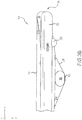
FIG. 2A illustrates a bottom view of an inflated evacuation slide, in accordance with various embodiments; -
FIG. 2B illustrates a side view of an inflated evacuation slide, in accordance with various embodiments; -
FIG. 3A illustrates a bottom view of an inflated evacuation slide, in accordance with various embodiments; -
FIG. 3B illustrates a side view of an inflated evacuation slide, in accordance with various embodiments; -
FIG. 4A illustrates a bottom view of an inflated evacuation slide, in accordance with various embodiments; -
FIG. 4B illustrates a side view of an inflated evacuation slide, in accordance with various embodiments; -
FIG. 5 illustrates a continuous tension coupling, in accordance with various embodiments; and -
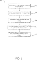
FIG. 6 illustrates a method for manufacturing a continuously tensioned truss strap, in accordance with various embodiments. - The detailed description of exemplary embodiments herein makes reference to the accompanying drawings, which show exemplary embodiments by way of illustration. While these exemplary embodiments are described in sufficient detail to enable those skilled in the art to practice the exemplary embodiments of the disclosure, it should be understood that other embodiments may be realized and that logical changes and adaptations in design and construction may be made in accordance with this disclosure and the teachings herein. Thus, the detailed description herein is presented for purposes of illustration only and not limitation. The steps recited in any of the method or process descriptions may be executed in any order and are not necessarily limited to the order presented.
- Furthermore, any reference to singular includes plural embodiments, and any reference to more than one component or step may include a singular embodiment or step. Also, any reference to attached, fixed, connected or the like may include permanent, removable, temporary, partial, full and/or any other possible attachment option. Additionally, any reference to without contact (or similar phrases) may also include reduced contact or minimal contact. Surface cross hatching lines may be used throughout the figures to denote different parts but not necessarily to denote the same or different materials.
- Slides according to the present disclosure may extend from an aircraft structure, such as a fuselage or a wing, for example, to an exit surface. An arched dropdown tube (also referred to as a protrusion) is provided to distribute the weight or load of an evacuee exiting the aircraft structure via the slide. The slide may comprise a dual lane slide comprising two side tubes (also referred to as inflatable members) and a center tube extending parallel to the lanes. The arched dropdown tube may be coupled between the two side tubes and may contact the center tube when the dual lane slide is inflated. Straps may couple the arched dropdown tube to the center tube. In this regard, the arched dropdown tube arrangement may form a truss structure with the slide for load distribution. In this regard, the arched dropdown tube and strap may increase structural integrity (i.e., beam strength or stiffness of the slide) while tending to minimize weight and pack volume of the slide.
- In various embodiments, a truss pillow (also referred to as a protrusion) and strap (or tension member) is provided to distribute the weight or load of an evacuee exiting the aircraft structure via the slide. The slide may comprise a dual lane slide comprising two side tubes and a center tube extending parallel to the lanes. The truss pillow may be coupled along any of the two side tubes or the center tube when the dual lane slide is inflated. Straps may couple the truss pillow to the side tubes or the center tube. In this regard, the truss pillow arrangement with the straps may form a truss structure with the slide for load distribution. In this regard, the truss pillow and strap may increase structural integrity (i.e., beam strength or stiffness of the slide) while tending to minimize weight and pack volume of the slide.
- With respect to
FIG. 2A , elements with like element numbering, as depicted inFIG. 1A andFIG. 1B , are intended to be the same and will not necessarily be repeated for the sake of clarity. With respect toFIGs. 3A through FIG. 4B elements with like element numbering, as depicted inFIGs. 1A through FIG. 2A , are intended to be the same and will not necessarily be repeated for the sake of clarity. - With combined reference to
FIG. 1A andFIG. 1B , anevacuation system 104 is illustrated, in accordance with various embodiments.Evacuation system 104 may compriseevacuation slide 100 coupled to anaircraft structure 102.Evacuation slide 100 may comprise ahead end 106 and atoe end 108.Head end 106 may be coupled toaircraft structure 102. In various embodiments,aircraft structure 102 may comprise a fuselage, a fairing, a wing, or any other portion of an aircraft.FIG. 1A andFIG. 1B illustrateevacuation slide 100 in a deployed position.Evacuation slide 100 may comprise an inflatable slide.FIG. 1A andFIG. 1B illustrateevacuation slide 100 in an inflated position.Evacuation slide 100 may comprise a dual lane slide comprising afirst lane 110 and asecond lane 112.Toe end 108 may contact anexit surface 170 in response toevacuation slide 100 being deployed. In various embodiments,evacuation slide 100 may be inflated in response to opening an emergency exit door.Evacuation slide 100 may comprise a slidingsurface 114. Slidingsurface 114 may comprise a dimension D. Dimension D may comprise the length of slidingsurface 114. Dimension D may comprise the length of the sloped portion ofevacuation slide 100, in response toevacuation slide 100 being in the deployed or inflated position, as illustrated inFIG. 1A . - With reference to
FIG. 2A , a bottom view ofevacuation slide 100 is shown having a dropdown tube, i.e.arched tube 220. An xyz-axes is provided for ease of illustration. As used herein, thebottom side 290 ofevacuation slide 100 may be the underside ofevacuation slide 100, or the side ofevacuation slide 100 opposite the sliding surface 114 (seeFIG. 1 ). Arched tube 220 (also referred to herein as a dropdown tube) may be coupled between side tube (also referred to herein as first side tube) 222 and side tube (also referred to herein as second side tube) 224.Arched tube 220 may be located at thebottom side 290 ofevacuation slide 100.Center tube 226 may be located betweenside tube 222 andside tube 224.Side tube 222,side tube 224, andcenter tube 226 may be disposed in parallel. Stated another way,side tube 222,side tube 224, andcenter tube 226 may each extend in a similar direction (i.e., in the y-direction) (also referred to herein as a first direction).Side tube 222,side tube 224, andcenter tube 226 may each extend in the xy-plane (also referred to herein as a first plane).Side tube 222,side tube 224, andcenter tube 226 may be coupled together attoe end 108 viacross tube 242.Cross tube 242 may be in contact with the exit surface (i.e.,exit surface 170 ofFIG. 1A ) in response toevacuation slide 100 being deployed.Side tube 222,side tube 224, andcenter tube 226 may be coupled together athead end 106 viacross tube 244. - With reference to
FIG. 2B , a side view ofevacuation slide 100 is illustrated, in accordance with various embodiments. An xyz-axes is provided for ease of illustration.Center tube 226 may be disposed belowside tubes center tube 226 may extend belowside tubes arched tube 220 may comprise a single, seamless arch between both ends ofarched tube 220.Center tube 226 may be in contact witharched tube 220 in response toevacuation slide 100 being deployed. Contact betweencenter tube 226 andarched tube 220 may allow loads to be transferred betweencenter tube 226 andarched tube 220. - In various embodiments, with combined reference to
FIG. 1B andFIG. 2A ,arched tube 220 may be located betweencross tube 242 andcross tube 244.Arched tube 220 may be located substantially half-way betweencross tube 242 andcross tube 244. In various embodiments,arched tube 220 may be located between twenty percent (20%) and eighty percent (80%) of dimension D fromtoe end 108, and in various embodiments, between thirty percent (30%) and seventy percent (70%) of dimension D fromtoe end 108, and in various embodiments, between forty percent (40%) and sixty percent (60%) of dimension D fromtoe end 108, and in various embodiments, between forty-five percent (45%) and fifty-five percent (55%) of dimension D fromtoe end 108. - In various embodiments,
side tube 222 andcenter tube 226 may at least partially define first lane 110 (seeFIG. 1 ).Side tube 224 andcenter tube 226 may at least partially define second lane 112 (seeFIG. 1 ). In various embodiments,arched tube 220 may extend substantially orthogonal (i.e., in the x-direction) toside tube 222,side tube 224, and/orcenter tube 226. In various embodiments,arched tube 220 may extend in the xz-plane (also referred to herein as a second plane) as illustrated inFIG. 2A . - In various embodiments, with reference to
FIG. 2A ,strap 230 may be coupled tocenter tube 226 atlocation 250 andlocation 252. In various embodiments,strap 230 may be attached tocenter tube 226 via an adhesive or glue.Strap 230 may be coupled toarched tube 220 by acontinuous tension coupling 500. In various embodiments,continuous tension coupling 500 may be attached toarched tube 220 via an adhesive or glue. In various embodiments,arched tube 220 may be configured to provide vertical support to slide 100 in response to a tension instrap 230. When viewingevacuation slide 100 from the bottom,strap 230 extends in a direction (i.e., the y-direction) parallel withcenter tube 226, as illustrated inFIG. 2A . Althoughstrap 230 may extend in a direction having a component orthogonal to the xy-plane,strap 230 may extend in a direction having a component in the y-direction. Stated another way, with additional reference toFIG. 2B ,strap 230 may comprise an angle theta (Θ) relative to centertube 226, when viewed from the side, as illustrated inFIG. 2B . In various embodiments, angle Θ may comprise between five degrees and eighty-five degrees (5°-85°), and in various embodiments, between ten degrees and fifty-five degrees (10°-55°), and in various embodiments, between ten degrees and forty degrees (10°-40°). - In various embodiments, with combined reference to
FIGs. 1B ,2A , and3A truss pillow 300 may be coupled to and located alongcenter tube 226 betweencross tube 242 andcross tube 244.Truss pillow 300 may be located substantially half-way betweencross tube 242 andcross tube 244. In various embodiments,truss pillow 300 may be located between twenty percent (20%) and eighty percent (80%) of dimension D fromtoe end 108, and in various embodiments, between thirty percent (30%) and seventy percent (70%) of dimension D fromtoe end 108, and in various embodiments, between forty percent (40%) and sixty percent (60%) of dimension D fromtoe end 108, and in various embodiments, between forty-five percent (45%) and fifty-five percent (55%) of dimension D fromtoe end 108. - In various embodiments, with reference to
FIGs. 3A and3B ,truss pillow 300 may be disposed belowside tubes center tube 226. Stated another way,center tube 226 may extend belowside tubes truss pillow 300 may protrude from belowcenter tube 226.Strap 230 may be coupled tocenter tube 226 atlocation 250 andlocation 252. In various embodiments,strap 230 may be attached tocenter tube 226 via an adhesive or glue.Strap 230 may be coupled totruss pillow 300 by acontinuous tension coupling 500. In various embodiments,truss pillow 300 may be configured to provide vertical support to slide 104 in response to a tension instraps 230. In various embodiments,continuous tension coupling 500 may be attached totruss pillow 300 via an adhesive or glue. When viewingevacuation slide 100 from the bottom,strap 230 extends in a direction (i.e., the y-direction) parallel withcenter tube 226, as illustrated inFIG. 3A . Althoughstrap 230 may extend in a direction having a component orthogonal to the xy-plane,strap 230 may extend in a direction having a component in the y-direction. Stated another way, with additional reference toFIG. 3B ,strap 230 may comprise an angle theta (Θ) relative to centertube 226, when viewed from the side, as illustrated inFIG. 2B . In various embodiments, angle Θ may comprise between five degrees and eighty-five degrees (5°-85°), and in various embodiments, between ten degrees and fifty-five degrees (10°-55°), and in various embodiments, between ten degrees and forty degrees (10°-40°). - In various embodiments, with combined reference to
FIGs. 1B ,2A , and4A ,truss pillows 400 andtruss pillows 402 may be coupled to and located alongside tube 222 andside tube 224. In various embodiments,truss pillows 400 may be located between ten percent (10%) and fifty percent (50%) of dimension D fromtoe end 108, and in various embodiments, between fifteen percent (15%) and forty percent (40%) of dimension D fromtoe end 108, and in various embodiments, between twenty percent (20%) and thirty percent (30%) of dimension D fromtoe end 108. In various embodiments,truss pillows 402 may be located sixty percent (60%) and one hundred percent (100%) of dimension D fromtoe end 108, and in various embodiments, between sixty-five percent (65%) and ninety percent (90%) of dimension D fromtoe end 108, and in various embodiments, between seventy percent (70%) and eighty percent (80%) of dimension D fromtoe end 108. - In various embodiments, with reference to
FIGs. 4A and4B ,truss pillows 400 andtruss pillows 402 may be disposed belowside tubes center tube 226. Stated another way,center tube 226 may extend belowside tubes truss pillows 400 andtruss pillows 402 may protrude from belowside tube 222 andside tube 224.Straps 404 may be coupled toside tube 222 andside tube 224 atlocation 406proximate toe end 108 andlocation 408 proximatehead end 106. In various embodiments, straps 404 may be attached toside tube 222 andside tube 224 via an adhesive or glue.Straps 404 may be coupled totruss pillows 400 andtruss pillows 402 by acontinuous tension coupling 500. In various embodiments,truss pillows 400 andtruss pillows 402 may be configured to provide vertical support to slide 104 in response to a tension instraps 404. In various embodiments,cross straps 410 are coupled acrosstruss pillows 400 and/or 402 and tend to prevent the pillows from rotating axially about the side tube (rotation about the y-axis). In various embodiments and with brief reference toFIG 5 , crossstraps 410 are coupled over or under (along the z-axis) acontinuous tension coupling 500 tobase portion 502 orsleeve portion 504. In various embodiments,cross straps 410 may be coupled tocenter tube 226 and to a side tube, such asside tube 222 orside tube 224. - With reference now to
FIG. 5 , acontinuous tension coupling 500 may comprise abase portion 502 and asleeve portion 504. In various embodiments,sleeve portion 504 may be coupled tobase portion 502 by stitching 506, or by any other suitable means known to those proficient in the art, forming avoid space 505 betweenbase portion 502 andsleeve portion 504.Sleeve portion 504, having afirst edge 507 and asecond edge 509, is coupled across atension strap 508, such as, for example with brief reference toFIGs. 2A ,3A , and4A ,strap 230 orstraps 404, andtension strap 508 may pass through thevoid space 505, open alongfirst edge 507 andsecond edge 509, betweenbase portion 502 andsleeve portion 504.Tension strap 508 tends to be restrained laterally by stitching 506 but tends to be unrestrained atfirst edge 507 andsecond edge 509 and, in response totension force 512 may slide along thebase portion 502 in thevoid space 505 between thesleeve portion 504. In various embodiments,base portion 502 may be coupled to asurface 510 by a glue or an adhesive such as a two part adhesive. In various embodiments, and with combined reference toFIGs. 2A ,3A , and4A ,surface 510 may be a truss pillow such as, for example,truss pillow 300 ortruss pillow 400 ortruss pillow 402, or may be a dropdown tube such as, for example,arched tube 220, or any other suitable part of an inflatable evacuation slide. - In various embodiments,
base portion 502 may comprise the same material as a sliding surface, such as, forexample sliding surface 114. In various embodiments, a strap, such asstrap 230, straps 404,cross straps 410, ortension strap 508 may comprise a rope, tape, ribbon, webbing, or any other suitable strap. In various embodiments, a strap may comprise a corded or woven strap. In various embodiments, a strap may comprise an elastomer. In various embodiments, a strap may comprise aramid, para-aramid such as that sold commercially as Kevlar®, nylon, ballistic nylon, polypropylene, polyethylene, or ultra-high-molecular-weight polyethylene such as that sold commercially as Dyneema® and Spectra®, polyester, cotton, or any other suitable material. - With reference to
FIG. 6 , Amethod 600 for manufacturing continuously tensioned truss strap is provided, in accordance with various embodiments.Method 600 may comprise providing a base portion, coupling a sleeve portion having a first edge and a second edge across thebase portion 602, forming a void space therebetween opening along the first edge and thesecond edge 604, and disposing a strap within thevoid space 606 configured to slide along the base portion in response to a tension force. In various embodiments,method 600 may further comprise coupling the base portion to one of a truss pillow or anarched tube 608. In various embodiments,method 600 may further comprise comprising coupling the strap at a first end proximate a toe end of an evacuation slide, applying the tension force to thestrap 610, and coupling the strap at a second end proximate a head end of the evacuation slide. - Benefits and other advantages have been described herein with regard to specific embodiments. Furthermore, the connecting lines shown in the various figures contained herein are intended to represent exemplary functional relationships and/or physical couplings between the various elements. It should be noted that many alternative or additional functional relationships or physical connections may be present in a practical system. However, the benefits, advantages, and any elements that may cause any benefit or advantage to occur or become more pronounced are not to be construed as critical, required, or essential features or elements of the disclosure. The scope of the disclosure is accordingly to be limited by nothing other than the appended claims, in which reference to an element in the singular is not intended to mean "one and only one" unless explicitly so stated, but rather "one or more." Moreover, where a phrase similar to "at least one of A, B, or C" is used in the claims, it is intended that the phrase be interpreted to mean that A alone may be present in an embodiment, B alone may be present in an embodiment, C alone may be present in an embodiment, or that any combination of the elements A, B and C may be present in a single embodiment; for example, A and B, A and C, B and C, or A and B and C.
- Systems, methods and apparatus are provided herein. In the detailed description herein, references to "various embodiments", "one embodiment", "an embodiment", "an example embodiment", etc., indicate that the embodiment described may include a particular feature, structure, or characteristic, but every embodiment may not necessarily include the particular feature, structure, or characteristic. Moreover, such phrases are not necessarily referring to the same embodiment. Further, when a particular feature, structure, or characteristic is described in connection with an embodiment, it is submitted that it is within the knowledge of one skilled in the art to affect such feature, structure, or characteristic in connection with other embodiments whether or not explicitly described. After reading the description, it will be apparent to one skilled in the relevant art(s) how to implement the disclosure in alternative embodiments.
- Furthermore, no element, component, or method step in the present disclosure is intended to be dedicated to the public regardless of whether the element, component, or method step is explicitly recited in the claims. As used herein, the terms "comprises", "comprising", or any other variation thereof, are intended to cover a non-exclusive inclusion, such that a process, method, article, or apparatus that comprises a list of elements does not include only those elements but may include other elements not expressly listed or inherent to such process, method, article, or apparatus.
Claims (15)
- A support arrangement for an inflatable evacuation system (104), comprising:an inflatable member (222, 224) configured to be elongated and stiffened in a longitudinal direction in response to being in an inflated condition;a protrusion (300) extending orthogonal to a surface of the inflatable member (222, 224);a tensile member (230) attached at at least two locations to the inflatable member (222, 224) on opposing sides of the protrusion (300) and being slidably engagable over the protrusion (300) so as to maintain about equal tension in the tensile member (230) on opposing sides of the protrusion; anda sleeve (504) attached to the protrusion (300) configured to maintain the tensile member (230) laterally relative to the protrusion (300) even as the tensile member (230) is able to slide longitudinally.
- The support arrangement of claim 1, further comprising a first strap (230) disposed within a void space (505), and preferably wherein the first strap (230) is configured to slide along a base portion (502) in response to a tension force, and more preferably wherein the base portion (502) is coupled to a surface (510).
- The support arrangement of claim 2, wherein the first strap (230) further comprises a first end coupled proximate a head end (106) of an evacuation slide and a second end coupled proximate a toe end (108) of the evacuation slide, and preferably wherein the base portion (502) comprises a same material as a sliding surface of the evacuation slide.
- The support arrangement of claim 2, further comprising a second strap (404) coupled to one of the base portion (502) or a sleeve portion (504).
- The support arrangement of claim 2, wherein the first strap (230) comprises one of a corded or woven material, an elastomer, an aramid, a para-aramid, a nylon, a ballistic nylon, a polypropylene, a polyethylene, an ultra-high-molecular-weight polyethylene, a polyester, or a cotton.
- An evacuation system for an aircraft structure comprising:an evacuation slide (100) coupled to the aircraft structure, the evacuation slide (100) comprising:a first side tube (222);a second side tube (224), the second side tube (224) and the first side tube (222) defining a lane of a sliding surface;a head end (106), a toe end (108); anda continuous tension coupling (500) comprising:a base portion (502);a sleeve portion (504) coupled across the base portion (502), wherein the sleeve portion (504) has a first edge (507) and a second edge (509); anda void space (505) between the base portion (502) and the sleeve portion (504), wherein the void space (505) is open along the first edge (507) and the second edge (509).
- The evacuation system for an aircraft structure of claim 6, further comprising a first strap (230) disposed within the void space (505).
- The evacuation system for an aircraft structure of claim 7, wherein the first strap (230) is configured to slide along the base portion (502) in response to a tension force.
- The evacuation system for an aircraft structure of claim 8, further comprising one of a truss pillow (300) or an arched tube (220) coupled to one of the first side tube (222), the second side tube (224), or a center tube (226).
- The evacuation system for an aircraft structure of claim 9, wherein the first strap (230) further comprises a first end coupled proximate the head end (106) of the evacuation slide and a second end coupled proximate the toe end (108) of the evacuation slide (100).
- The evacuation system for an aircraft structure of claim 10, wherein the continuous tension coupling (500) is coupled to one of the truss pillow (300) or the arched tube (220).
- The evacuation system for an aircraft structure of claim 11, wherein one of the truss pillow (300) or the arched tube (220) is configured to provide vertical support to the evacuation slide (100) in response to the tension force.
- The evacuation system for an aircraft structure of claim 12, comprising a second strap (404) coupled to one of the base portion (502) or the sleeve portion (504) and coupled to the center tube (226), and preferably wherein the base portion (502) comprises a same material as the sliding surface of the evacuation slide (100).
- A method for manufacturing a continuously tensioned truss strap, comprising:providing a base portion (502);coupling a sleeve portion (504) having a first edge (507) and a second edge (509) across the base portion (502);forming a void space (505) therebetween opening along the first edge (507) and the second edge (509); and disposing a strap (230) within the void space (505) configured to slide along the base portion (502) in response to a tension force.
- The method according to claim 14, further comprising coupling the base portion (502) to one of a truss pillow (300) or an arched tube (220), and preferably further comprising coupling the strap (230) at a first end proximate a toe end (108) of an evacuation slide (100), applying the tension force to the strap (230), and coupling the strap (230) at a second end proximate a head end (106) of the evacuation slide (100).
Applications Claiming Priority (1)
| Application Number | Priority Date | Filing Date | Title |
|---|---|---|---|
| US15/714,979 US10647437B2 (en) | 2017-09-25 | 2017-09-25 | Continuously tensioned truss strap |
Publications (3)
| Publication Number | Publication Date |
|---|---|
| EP3459854A2 true EP3459854A2 (en) | 2019-03-27 |
| EP3459854A3 EP3459854A3 (en) | 2019-06-19 |
| EP3459854B1 EP3459854B1 (en) | 2021-07-28 |
Family
ID=63683052
Family Applications (1)
| Application Number | Title | Priority Date | Filing Date |
|---|---|---|---|
| EP18196248.1A Active EP3459854B1 (en) | 2017-09-25 | 2018-09-24 | Continuously tensioned truss strap |
Country Status (3)
| Country | Link |
|---|---|
| US (3) | US10647437B2 (en) |
| EP (1) | EP3459854B1 (en) |
| BR (1) | BR102018014067A2 (en) |
Cited By (2)
| Publication number | Priority date | Publication date | Assignee | Title |
|---|---|---|---|---|
| US10647437B2 (en) * | 2017-09-25 | 2020-05-12 | Goodrich Corporation | Continuously tensioned truss strap |
| EP3816051A1 (en) * | 2019-10-31 | 2021-05-05 | B/E Aerospace, Inc. | Integrated truss restraint |
Families Citing this family (3)
| Publication number | Priority date | Publication date | Assignee | Title |
|---|---|---|---|---|
| US11040778B2 (en) * | 2018-11-16 | 2021-06-22 | Goodrich Corporation | Multi-staged suspension line attenuator |
| US11130586B2 (en) * | 2019-09-25 | 2021-09-28 | Goodrich Corporation | Lane dividing apparatus |
| US11554871B2 (en) * | 2020-01-06 | 2023-01-17 | Goodrich Corporation | Truss strap integrated geometric restraint |
Family Cites Families (35)
| Publication number | Priority date | Publication date | Assignee | Title |
|---|---|---|---|---|
| FR96018E (en) | 1967-10-23 | 1972-05-19 | Goodrich Co B F | Pneumatic rescue slide. |
| US3860984A (en) * | 1973-06-25 | 1975-01-21 | Goodrich Co B F | Inflatable life raft escape slide |
| US4018321A (en) * | 1976-05-21 | 1977-04-19 | The B. F. Goodrich Company | Escape slide and platform assembly |
| US4519782A (en) * | 1980-02-19 | 1985-05-28 | The B. F. Goodrich Company | Escape slide and life raft |
| US4434870A (en) * | 1982-11-22 | 1984-03-06 | The B. F. Goodrich Company | Evacuation slide device |
| US4723628A (en) * | 1984-12-03 | 1988-02-09 | The B. F. Goodrich Company | Evacuation slide |
| US5975467A (en) * | 1998-08-06 | 1999-11-02 | Air Cruisers Company | Inflatable evacuation slide |
| US6536715B1 (en) | 2001-06-15 | 2003-03-25 | Air Cruisers Company | Inflatable evacuation slide with arch support |
| US6454220B1 (en) * | 2001-10-11 | 2002-09-24 | Goodrich Coporation | Evacuation slide with toe end center support member |
| US6581334B2 (en) * | 2001-11-02 | 2003-06-24 | Goodrich Corporation | High strength T-joint for inflatable tube structures |
| US6814183B2 (en) * | 2002-10-17 | 2004-11-09 | Goodrich Corporation | Extensible evacuation slide |
| US6877696B2 (en) * | 2002-12-19 | 2005-04-12 | Goodrich Corporation | Evacuation slide with leading edge spoiler |
| US6966414B2 (en) * | 2003-12-02 | 2005-11-22 | Goodrich Corporation | Elevated inflatable emergency evacuation slide illumination |
| NZ561024A (en) | 2005-03-12 | 2009-12-24 | Sealed Air Corp | Inflatable containers |
| US7090168B1 (en) * | 2005-05-16 | 2006-08-15 | Air Cruisers Company | Catenary girt arrangement for emergency evacuation slides |
| US9725181B2 (en) * | 2015-07-17 | 2017-08-08 | Goodrich Corporation | Off wing evacuation system control strap |
| US10246195B2 (en) * | 2016-09-15 | 2019-04-02 | Goodrich Corporation | Arched inflatable structure for evacuation slide systems |
| US10464682B2 (en) * | 2017-01-06 | 2019-11-05 | Goodrich Corporation | Negative lift evacuation slide |
| US10703495B2 (en) * | 2017-01-13 | 2020-07-07 | Goodrich Corporation | Secondary release arrangement for evacuation slide systems |
| US10486818B2 (en) * | 2017-01-17 | 2019-11-26 | Goodrich Corporation | Shock absorbing evacuation system restraint |
| US10457406B2 (en) * | 2017-03-22 | 2019-10-29 | Goodrich Corporation | Dual configuration evacuation assembly |
| US10556698B2 (en) * | 2017-03-22 | 2020-02-11 | Goodrich Corporation | Asymmetric yoke |
| US10836498B2 (en) * | 2017-03-22 | 2020-11-17 | Goodrich Corporation | Light weight variable force restraint |
| US10647436B2 (en) * | 2017-04-27 | 2020-05-12 | Goodrich Corporation | Yoke strap with shock absorber |
| US10793280B2 (en) * | 2017-05-12 | 2020-10-06 | Goodrich Corporation | Evacuation system with wind lift deterrent |
| US10189573B2 (en) * | 2017-05-19 | 2019-01-29 | Goodrich Corporation | Off-wing slide raft |
| IT201700086155A1 (en) * | 2017-07-27 | 2019-01-27 | Progetech S R L | Modular and adjustable emergency evacuation system. |
| US10000292B1 (en) * | 2017-07-28 | 2018-06-19 | Goodrich Corporation | Multipurpose lane divider for evacuation slide |
| US10647437B2 (en) * | 2017-09-25 | 2020-05-12 | Goodrich Corporation | Continuously tensioned truss strap |
| US10710733B2 (en) * | 2017-10-17 | 2020-07-14 | Goodrich Corporation | Evacuation slide with aspirator retention strap |
| WO2019084263A1 (en) * | 2017-10-25 | 2019-05-02 | Collier Winsome | Safety system including evacuation slide and floatation raft, and methods of use |
| US11066176B2 (en) * | 2018-04-12 | 2021-07-20 | Goodrich Corporation | Canopy support lane divider |
| US20190316416A1 (en) * | 2018-04-13 | 2019-10-17 | Goodrich Corporation | Rescue Ladder |
| US11492129B2 (en) * | 2020-01-17 | 2022-11-08 | Goodrich Corporation | Evacuation slide with safety gate readiness indicator |
| CA3214032A1 (en) * | 2021-03-31 | 2022-10-06 | ZeroAvia, Inc. | Aircraft evacuation system with hydrogen inflation |
-
2017
- 2017-09-25 US US15/714,979 patent/US10647437B2/en active Active
-
2018
- 2018-07-10 BR BR102018014067-1A patent/BR102018014067A2/en not_active IP Right Cessation
- 2018-09-24 EP EP18196248.1A patent/EP3459854B1/en active Active
-
2020
- 2020-04-09 US US16/844,658 patent/US11434013B2/en active Active
-
2022
- 2022-08-19 US US17/891,929 patent/US11718407B2/en active Active
Non-Patent Citations (1)
| Title |
|---|
| None |
Cited By (5)
| Publication number | Priority date | Publication date | Assignee | Title |
|---|---|---|---|---|
| US10647437B2 (en) * | 2017-09-25 | 2020-05-12 | Goodrich Corporation | Continuously tensioned truss strap |
| US11434013B2 (en) | 2017-09-25 | 2022-09-06 | Goodrich Corporation | Continuously tensioned truss strap |
| US20220402619A1 (en) * | 2017-09-25 | 2022-12-22 | Goodrich Corporation | Continuously tensioned truss strap |
| US11718407B2 (en) | 2017-09-25 | 2023-08-08 | Goodrich Corporation | Continuously tensioned truss strap |
| EP3816051A1 (en) * | 2019-10-31 | 2021-05-05 | B/E Aerospace, Inc. | Integrated truss restraint |
Also Published As
| Publication number | Publication date |
|---|---|
| US11718407B2 (en) | 2023-08-08 |
| US20220402619A1 (en) | 2022-12-22 |
| US11434013B2 (en) | 2022-09-06 |
| US20190092482A1 (en) | 2019-03-28 |
| EP3459854B1 (en) | 2021-07-28 |
| EP3459854A3 (en) | 2019-06-19 |
| US10647437B2 (en) | 2020-05-12 |
| BR102018014067A2 (en) | 2019-04-16 |
| US20200255158A1 (en) | 2020-08-13 |
Similar Documents
| Publication | Publication Date | Title |
|---|---|---|
| US11718407B2 (en) | Continuously tensioned truss strap | |
| US10246195B2 (en) | Arched inflatable structure for evacuation slide systems | |
| US5975467A (en) | Inflatable evacuation slide | |
| EP3403931B1 (en) | Off-wing slide raft | |
| EP0893343A2 (en) | Inflatable escape slide assembly | |
| EP1410986A2 (en) | Breakaway lacing for emergency evacuation slide | |
| CN103261020A (en) | Articulation for joining fuselage sections and related method | |
| US9399519B2 (en) | Self-tensioning girt | |
| US20170320583A1 (en) | Systems and methods for retaining removable panel when deploying evacuation system | |
| US20220388671A1 (en) | Systems and methods for soft cover attachment | |
| US8864080B2 (en) | Expendable aerial delivery system | |
| US10953994B2 (en) | Aircraft evacuation system with an integrated spoiler | |
| EP3272643B1 (en) | Aircraft or spacecraft passenger cabin partition | |
| US11192657B2 (en) | Evacuation slide having immediately extending ballast bags | |
| DE60131555T2 (en) | FLEXIBLE MOUNTING SYSTEM FOR AMBIENT DENSITY PARACHUES AND OTHER SAFETY DEVICES | |
| US10196124B2 (en) | Aircraft external part with inflatable panels | |
| EP3348485B1 (en) | Continuously restrained evacuation system | |
| US11014679B2 (en) | Sill height morphing evacuation slide | |
| US9212520B1 (en) | End guide for cord attachment device | |
| CA3002860C (en) | Parachute slider with stiffening elements | |
| US5123616A (en) | High efficiency, low weight and volume energy absorbent seam | |
| RU164559U1 (en) | FREIGHT NETWORK FOR HELICOPTER LUGGAGE | |
| EP4169838A1 (en) | Parachute riser cradle |
Legal Events
| Date | Code | Title | Description |
|---|---|---|---|
| PUAI | Public reference made under article 153(3) epc to a published international application that has entered the european phase |
Free format text: ORIGINAL CODE: 0009012 |
|
| STAA | Information on the status of an ep patent application or granted ep patent |
Free format text: STATUS: THE APPLICATION HAS BEEN PUBLISHED |
|
| AK | Designated contracting states |
Kind code of ref document: A2 Designated state(s): AL AT BE BG CH CY CZ DE DK EE ES FI FR GB GR HR HU IE IS IT LI LT LU LV MC MK MT NL NO PL PT RO RS SE SI SK SM TR |
|
| AX | Request for extension of the european patent |
Extension state: BA ME |
|
| PUAL | Search report despatched |
Free format text: ORIGINAL CODE: 0009013 |
|
| AK | Designated contracting states |
Kind code of ref document: A3 Designated state(s): AL AT BE BG CH CY CZ DE DK EE ES FI FR GB GR HR HU IE IS IT LI LT LU LV MC MK MT NL NO PL PT RO RS SE SI SK SM TR |
|
| AX | Request for extension of the european patent |
Extension state: BA ME |
|
| RIC1 | Information provided on ipc code assigned before grant |
Ipc: B64D 25/14 20060101AFI20190516BHEP Ipc: A62B 1/20 20060101ALN20190516BHEP |
|
| STAA | Information on the status of an ep patent application or granted ep patent |
Free format text: STATUS: REQUEST FOR EXAMINATION WAS MADE |
|
| 17P | Request for examination filed |
Effective date: 20191219 |
|
| RBV | Designated contracting states (corrected) |
Designated state(s): AL AT BE BG CH CY CZ DE DK EE ES FI FR GB GR HR HU IE IS IT LI LT LU LV MC MK MT NL NO PL PT RO RS SE SI SK SM TR |
|
| RIN1 | Information on inventor provided before grant (corrected) |
Inventor name: HARTMAN, DREW Inventor name: VOLNY, JARO S. |
|
| STAA | Information on the status of an ep patent application or granted ep patent |
Free format text: STATUS: EXAMINATION IS IN PROGRESS |
|
| 17Q | First examination report despatched |
Effective date: 20200525 |
|
| GRAP | Despatch of communication of intention to grant a patent |
Free format text: ORIGINAL CODE: EPIDOSNIGR1 |
|
| STAA | Information on the status of an ep patent application or granted ep patent |
Free format text: STATUS: GRANT OF PATENT IS INTENDED |
|
| RIC1 | Information provided on ipc code assigned before grant |
Ipc: B64D 25/14 20060101AFI20210121BHEP Ipc: A62B 1/20 20060101ALN20210121BHEP |
|
| INTG | Intention to grant announced |
Effective date: 20210219 |
|
| RIC1 | Information provided on ipc code assigned before grant |
Ipc: A62B 1/20 20060101ALN20210208BHEP Ipc: B64D 25/14 20060101AFI20210208BHEP |
|
| RIN1 | Information on inventor provided before grant (corrected) |
Inventor name: VOLNY, JARO S. Inventor name: HARTMAN, DREW |
|
| GRAS | Grant fee paid |
Free format text: ORIGINAL CODE: EPIDOSNIGR3 |
|
| GRAA | (expected) grant |
Free format text: ORIGINAL CODE: 0009210 |
|
| STAA | Information on the status of an ep patent application or granted ep patent |
Free format text: STATUS: THE PATENT HAS BEEN GRANTED |
|
| AK | Designated contracting states |
Kind code of ref document: B1 Designated state(s): AL AT BE BG CH CY CZ DE DK EE ES FI FR GB GR HR HU IE IS IT LI LT LU LV MC MK MT NL NO PL PT RO RS SE SI SK SM TR |
|
| REG | Reference to a national code |
Ref country code: GB Ref legal event code: FG4D |
|
| REG | Reference to a national code |
Ref country code: CH Ref legal event code: EP |
|
| REG | Reference to a national code |
Ref country code: DE Ref legal event code: R096 Ref document number: 602018020703 Country of ref document: DE |
|
| REG | Reference to a national code |
Ref country code: AT Ref legal event code: REF Ref document number: 1414550 Country of ref document: AT Kind code of ref document: T Effective date: 20210815 |
|
| REG | Reference to a national code |
Ref country code: IE Ref legal event code: FG4D |
|
| REG | Reference to a national code |
Ref country code: LT Ref legal event code: MG9D |
|
| REG | Reference to a national code |
Ref country code: NL Ref legal event code: MP Effective date: 20210728 |
|
| REG | Reference to a national code |
Ref country code: AT Ref legal event code: MK05 Ref document number: 1414550 Country of ref document: AT Kind code of ref document: T Effective date: 20210728 |
|
| PG25 | Lapsed in a contracting state [announced via postgrant information from national office to epo] |
Ref country code: FI Free format text: LAPSE BECAUSE OF FAILURE TO SUBMIT A TRANSLATION OF THE DESCRIPTION OR TO PAY THE FEE WITHIN THE PRESCRIBED TIME-LIMIT Effective date: 20210728 Ref country code: ES Free format text: LAPSE BECAUSE OF FAILURE TO SUBMIT A TRANSLATION OF THE DESCRIPTION OR TO PAY THE FEE WITHIN THE PRESCRIBED TIME-LIMIT Effective date: 20210728 Ref country code: HR Free format text: LAPSE BECAUSE OF FAILURE TO SUBMIT A TRANSLATION OF THE DESCRIPTION OR TO PAY THE FEE WITHIN THE PRESCRIBED TIME-LIMIT Effective date: 20210728 Ref country code: SE Free format text: LAPSE BECAUSE OF FAILURE TO SUBMIT A TRANSLATION OF THE DESCRIPTION OR TO PAY THE FEE WITHIN THE PRESCRIBED TIME-LIMIT Effective date: 20210728 Ref country code: RS Free format text: LAPSE BECAUSE OF FAILURE TO SUBMIT A TRANSLATION OF THE DESCRIPTION OR TO PAY THE FEE WITHIN THE PRESCRIBED TIME-LIMIT Effective date: 20210728 Ref country code: NO Free format text: LAPSE BECAUSE OF FAILURE TO SUBMIT A TRANSLATION OF THE DESCRIPTION OR TO PAY THE FEE WITHIN THE PRESCRIBED TIME-LIMIT Effective date: 20211028 Ref country code: PT Free format text: LAPSE BECAUSE OF FAILURE TO SUBMIT A TRANSLATION OF THE DESCRIPTION OR TO PAY THE FEE WITHIN THE PRESCRIBED TIME-LIMIT Effective date: 20211129 Ref country code: NL Free format text: LAPSE BECAUSE OF FAILURE TO SUBMIT A TRANSLATION OF THE DESCRIPTION OR TO PAY THE FEE WITHIN THE PRESCRIBED TIME-LIMIT Effective date: 20210728 Ref country code: LT Free format text: LAPSE BECAUSE OF FAILURE TO SUBMIT A TRANSLATION OF THE DESCRIPTION OR TO PAY THE FEE WITHIN THE PRESCRIBED TIME-LIMIT Effective date: 20210728 Ref country code: BG Free format text: LAPSE BECAUSE OF FAILURE TO SUBMIT A TRANSLATION OF THE DESCRIPTION OR TO PAY THE FEE WITHIN THE PRESCRIBED TIME-LIMIT Effective date: 20211028 Ref country code: AT Free format text: LAPSE BECAUSE OF FAILURE TO SUBMIT A TRANSLATION OF THE DESCRIPTION OR TO PAY THE FEE WITHIN THE PRESCRIBED TIME-LIMIT Effective date: 20210728 |
|
| PG25 | Lapsed in a contracting state [announced via postgrant information from national office to epo] |
Ref country code: PL Free format text: LAPSE BECAUSE OF FAILURE TO SUBMIT A TRANSLATION OF THE DESCRIPTION OR TO PAY THE FEE WITHIN THE PRESCRIBED TIME-LIMIT Effective date: 20210728 Ref country code: LV Free format text: LAPSE BECAUSE OF FAILURE TO SUBMIT A TRANSLATION OF THE DESCRIPTION OR TO PAY THE FEE WITHIN THE PRESCRIBED TIME-LIMIT Effective date: 20210728 Ref country code: GR Free format text: LAPSE BECAUSE OF FAILURE TO SUBMIT A TRANSLATION OF THE DESCRIPTION OR TO PAY THE FEE WITHIN THE PRESCRIBED TIME-LIMIT Effective date: 20211029 |
|
| PG25 | Lapsed in a contracting state [announced via postgrant information from national office to epo] |
Ref country code: DK Free format text: LAPSE BECAUSE OF FAILURE TO SUBMIT A TRANSLATION OF THE DESCRIPTION OR TO PAY THE FEE WITHIN THE PRESCRIBED TIME-LIMIT Effective date: 20210728 |
|
| REG | Reference to a national code |
Ref country code: DE Ref legal event code: R097 Ref document number: 602018020703 Country of ref document: DE Ref country code: CH Ref legal event code: PL |
|
| REG | Reference to a national code |
Ref country code: BE Ref legal event code: MM Effective date: 20210930 |
|
| PG25 | Lapsed in a contracting state [announced via postgrant information from national office to epo] |
Ref country code: SM Free format text: LAPSE BECAUSE OF FAILURE TO SUBMIT A TRANSLATION OF THE DESCRIPTION OR TO PAY THE FEE WITHIN THE PRESCRIBED TIME-LIMIT Effective date: 20210728 Ref country code: SK Free format text: LAPSE BECAUSE OF FAILURE TO SUBMIT A TRANSLATION OF THE DESCRIPTION OR TO PAY THE FEE WITHIN THE PRESCRIBED TIME-LIMIT Effective date: 20210728 Ref country code: RO Free format text: LAPSE BECAUSE OF FAILURE TO SUBMIT A TRANSLATION OF THE DESCRIPTION OR TO PAY THE FEE WITHIN THE PRESCRIBED TIME-LIMIT Effective date: 20210728 Ref country code: MC Free format text: LAPSE BECAUSE OF FAILURE TO SUBMIT A TRANSLATION OF THE DESCRIPTION OR TO PAY THE FEE WITHIN THE PRESCRIBED TIME-LIMIT Effective date: 20210728 Ref country code: EE Free format text: LAPSE BECAUSE OF FAILURE TO SUBMIT A TRANSLATION OF THE DESCRIPTION OR TO PAY THE FEE WITHIN THE PRESCRIBED TIME-LIMIT Effective date: 20210728 Ref country code: CZ Free format text: LAPSE BECAUSE OF FAILURE TO SUBMIT A TRANSLATION OF THE DESCRIPTION OR TO PAY THE FEE WITHIN THE PRESCRIBED TIME-LIMIT Effective date: 20210728 Ref country code: AL Free format text: LAPSE BECAUSE OF FAILURE TO SUBMIT A TRANSLATION OF THE DESCRIPTION OR TO PAY THE FEE WITHIN THE PRESCRIBED TIME-LIMIT Effective date: 20210728 |
|
| PLBE | No opposition filed within time limit |
Free format text: ORIGINAL CODE: 0009261 |
|
| STAA | Information on the status of an ep patent application or granted ep patent |
Free format text: STATUS: NO OPPOSITION FILED WITHIN TIME LIMIT |
|
| 26N | No opposition filed |
Effective date: 20220429 |
|
| PG25 | Lapsed in a contracting state [announced via postgrant information from national office to epo] |
Ref country code: LU Free format text: LAPSE BECAUSE OF NON-PAYMENT OF DUE FEES Effective date: 20210924 Ref country code: IE Free format text: LAPSE BECAUSE OF NON-PAYMENT OF DUE FEES Effective date: 20210924 Ref country code: BE Free format text: LAPSE BECAUSE OF NON-PAYMENT OF DUE FEES Effective date: 20210930 |
|
| PG25 | Lapsed in a contracting state [announced via postgrant information from national office to epo] |
Ref country code: LI Free format text: LAPSE BECAUSE OF NON-PAYMENT OF DUE FEES Effective date: 20210930 Ref country code: CH Free format text: LAPSE BECAUSE OF NON-PAYMENT OF DUE FEES Effective date: 20210930 |
|
| GBPC | Gb: european patent ceased through non-payment of renewal fee |
Effective date: 20220924 |
|
| P01 | Opt-out of the competence of the unified patent court (upc) registered |
Effective date: 20230521 |
|
| PG25 | Lapsed in a contracting state [announced via postgrant information from national office to epo] |
Ref country code: CY Free format text: LAPSE BECAUSE OF FAILURE TO SUBMIT A TRANSLATION OF THE DESCRIPTION OR TO PAY THE FEE WITHIN THE PRESCRIBED TIME-LIMIT Effective date: 20210728 |
|
| PG25 | Lapsed in a contracting state [announced via postgrant information from national office to epo] |
Ref country code: HU Free format text: LAPSE BECAUSE OF FAILURE TO SUBMIT A TRANSLATION OF THE DESCRIPTION OR TO PAY THE FEE WITHIN THE PRESCRIBED TIME-LIMIT; INVALID AB INITIO Effective date: 20180924 |
|
| PG25 | Lapsed in a contracting state [announced via postgrant information from national office to epo] |
Ref country code: GB Free format text: LAPSE BECAUSE OF NON-PAYMENT OF DUE FEES Effective date: 20220924 |
|
| PG25 | Lapsed in a contracting state [announced via postgrant information from national office to epo] |
Ref country code: MK Free format text: LAPSE BECAUSE OF FAILURE TO SUBMIT A TRANSLATION OF THE DESCRIPTION OR TO PAY THE FEE WITHIN THE PRESCRIBED TIME-LIMIT Effective date: 20210728 |
|
| PG25 | Lapsed in a contracting state [announced via postgrant information from national office to epo] |
Ref country code: MT Free format text: LAPSE BECAUSE OF FAILURE TO SUBMIT A TRANSLATION OF THE DESCRIPTION OR TO PAY THE FEE WITHIN THE PRESCRIBED TIME-LIMIT Effective date: 20210728 |
|
| PGFP | Annual fee paid to national office [announced via postgrant information from national office to epo] |
Ref country code: DE Payment date: 20250820 Year of fee payment: 8 |
|
| PGFP | Annual fee paid to national office [announced via postgrant information from national office to epo] |
Ref country code: IT Payment date: 20250820 Year of fee payment: 8 |
|
| PGFP | Annual fee paid to national office [announced via postgrant information from national office to epo] |
Ref country code: FR Payment date: 20250820 Year of fee payment: 8 |
|
| PG25 | Lapsed in a contracting state [announced via postgrant information from national office to epo] |
Ref country code: TR Free format text: LAPSE BECAUSE OF FAILURE TO SUBMIT A TRANSLATION OF THE DESCRIPTION OR TO PAY THE FEE WITHIN THE PRESCRIBED TIME-LIMIT Effective date: 20210728 |