EP3459708A1 - An extrusion system including an edge encapsulation block - Google Patents
An extrusion system including an edge encapsulation block Download PDFInfo
- Publication number
- EP3459708A1 EP3459708A1 EP18196487.5A EP18196487A EP3459708A1 EP 3459708 A1 EP3459708 A1 EP 3459708A1 EP 18196487 A EP18196487 A EP 18196487A EP 3459708 A1 EP3459708 A1 EP 3459708A1
- Authority
- EP
- European Patent Office
- Prior art keywords
- edge
- block
- encapsulation
- channel
- central
- Prior art date
- Legal status (The legal status is an assumption and is not a legal conclusion. Google has not performed a legal analysis and makes no representation as to the accuracy of the status listed.)
- Withdrawn
Links
- 238000005538 encapsulation Methods 0.000 title claims abstract description 124
- 238000001125 extrusion Methods 0.000 title claims abstract description 101
- 239000000463 material Substances 0.000 claims abstract description 160
- 238000004891 communication Methods 0.000 claims description 14
- 239000012530 fluid Substances 0.000 claims description 14
- 238000000034 method Methods 0.000 description 8
- 230000008569 process Effects 0.000 description 5
- 239000002356 single layer Substances 0.000 description 5
- 239000002699 waste material Substances 0.000 description 4
- 238000009966 trimming Methods 0.000 description 3
- 230000015572 biosynthetic process Effects 0.000 description 2
- 230000008878 coupling Effects 0.000 description 2
- 238000010168 coupling process Methods 0.000 description 2
- 238000005859 coupling reaction Methods 0.000 description 2
- 230000009969 flowable effect Effects 0.000 description 2
- 239000011347 resin Substances 0.000 description 2
- 229920005989 resin Polymers 0.000 description 2
- 239000000853 adhesive Substances 0.000 description 1
- 230000001070 adhesive effect Effects 0.000 description 1
- 239000011248 coating agent Substances 0.000 description 1
- 238000000576 coating method Methods 0.000 description 1
- 230000000295 complement effect Effects 0.000 description 1
- 238000010276 construction Methods 0.000 description 1
- 230000008676 import Effects 0.000 description 1
- 230000005012 migration Effects 0.000 description 1
- 238000013508 migration Methods 0.000 description 1
- 229920001169 thermoplastic Polymers 0.000 description 1
- 239000012815 thermoplastic material Substances 0.000 description 1
- 239000004416 thermosoftening plastic Substances 0.000 description 1
- 238000011144 upstream manufacturing Methods 0.000 description 1
Images





Classifications
-
- B—PERFORMING OPERATIONS; TRANSPORTING
- B29—WORKING OF PLASTICS; WORKING OF SUBSTANCES IN A PLASTIC STATE IN GENERAL
- B29C—SHAPING OR JOINING OF PLASTICS; SHAPING OF MATERIAL IN A PLASTIC STATE, NOT OTHERWISE PROVIDED FOR; AFTER-TREATMENT OF THE SHAPED PRODUCTS, e.g. REPAIRING
- B29C48/00—Extrusion moulding, i.e. expressing the moulding material through a die or nozzle which imparts the desired form; Apparatus therefor
- B29C48/25—Component parts, details or accessories; Auxiliary operations
- B29C48/30—Extrusion nozzles or dies
-
- B—PERFORMING OPERATIONS; TRANSPORTING
- B29—WORKING OF PLASTICS; WORKING OF SUBSTANCES IN A PLASTIC STATE IN GENERAL
- B29C—SHAPING OR JOINING OF PLASTICS; SHAPING OF MATERIAL IN A PLASTIC STATE, NOT OTHERWISE PROVIDED FOR; AFTER-TREATMENT OF THE SHAPED PRODUCTS, e.g. REPAIRING
- B29C48/00—Extrusion moulding, i.e. expressing the moulding material through a die or nozzle which imparts the desired form; Apparatus therefor
- B29C48/03—Extrusion moulding, i.e. expressing the moulding material through a die or nozzle which imparts the desired form; Apparatus therefor characterised by the shape of the extruded material at extrusion
- B29C48/07—Flat, e.g. panels
-
- B—PERFORMING OPERATIONS; TRANSPORTING
- B29—WORKING OF PLASTICS; WORKING OF SUBSTANCES IN A PLASTIC STATE IN GENERAL
- B29C—SHAPING OR JOINING OF PLASTICS; SHAPING OF MATERIAL IN A PLASTIC STATE, NOT OTHERWISE PROVIDED FOR; AFTER-TREATMENT OF THE SHAPED PRODUCTS, e.g. REPAIRING
- B29C48/00—Extrusion moulding, i.e. expressing the moulding material through a die or nozzle which imparts the desired form; Apparatus therefor
- B29C48/03—Extrusion moulding, i.e. expressing the moulding material through a die or nozzle which imparts the desired form; Apparatus therefor characterised by the shape of the extruded material at extrusion
- B29C48/07—Flat, e.g. panels
- B29C48/08—Flat, e.g. panels flexible, e.g. films
-
- B—PERFORMING OPERATIONS; TRANSPORTING
- B29—WORKING OF PLASTICS; WORKING OF SUBSTANCES IN A PLASTIC STATE IN GENERAL
- B29C—SHAPING OR JOINING OF PLASTICS; SHAPING OF MATERIAL IN A PLASTIC STATE, NOT OTHERWISE PROVIDED FOR; AFTER-TREATMENT OF THE SHAPED PRODUCTS, e.g. REPAIRING
- B29C48/00—Extrusion moulding, i.e. expressing the moulding material through a die or nozzle which imparts the desired form; Apparatus therefor
- B29C48/16—Articles comprising two or more components, e.g. co-extruded layers
- B29C48/18—Articles comprising two or more components, e.g. co-extruded layers the components being layers
- B29C48/19—Articles comprising two or more components, e.g. co-extruded layers the components being layers the layers being joined at their edges
-
- B—PERFORMING OPERATIONS; TRANSPORTING
- B29—WORKING OF PLASTICS; WORKING OF SUBSTANCES IN A PLASTIC STATE IN GENERAL
- B29C—SHAPING OR JOINING OF PLASTICS; SHAPING OF MATERIAL IN A PLASTIC STATE, NOT OTHERWISE PROVIDED FOR; AFTER-TREATMENT OF THE SHAPED PRODUCTS, e.g. REPAIRING
- B29C48/00—Extrusion moulding, i.e. expressing the moulding material through a die or nozzle which imparts the desired form; Apparatus therefor
- B29C48/25—Component parts, details or accessories; Auxiliary operations
- B29C48/255—Flow control means, e.g. valves
-
- B—PERFORMING OPERATIONS; TRANSPORTING
- B29—WORKING OF PLASTICS; WORKING OF SUBSTANCES IN A PLASTIC STATE IN GENERAL
- B29C—SHAPING OR JOINING OF PLASTICS; SHAPING OF MATERIAL IN A PLASTIC STATE, NOT OTHERWISE PROVIDED FOR; AFTER-TREATMENT OF THE SHAPED PRODUCTS, e.g. REPAIRING
- B29C48/00—Extrusion moulding, i.e. expressing the moulding material through a die or nozzle which imparts the desired form; Apparatus therefor
- B29C48/25—Component parts, details or accessories; Auxiliary operations
- B29C48/255—Flow control means, e.g. valves
- B29C48/2556—Flow control means, e.g. valves provided in or in the proximity of dies
-
- B—PERFORMING OPERATIONS; TRANSPORTING
- B29—WORKING OF PLASTICS; WORKING OF SUBSTANCES IN A PLASTIC STATE IN GENERAL
- B29C—SHAPING OR JOINING OF PLASTICS; SHAPING OF MATERIAL IN A PLASTIC STATE, NOT OTHERWISE PROVIDED FOR; AFTER-TREATMENT OF THE SHAPED PRODUCTS, e.g. REPAIRING
- B29C48/00—Extrusion moulding, i.e. expressing the moulding material through a die or nozzle which imparts the desired form; Apparatus therefor
- B29C48/25—Component parts, details or accessories; Auxiliary operations
- B29C48/268—Throttling of the flow, e.g. for cooperating with plasticising elements or for degassing
-
- B—PERFORMING OPERATIONS; TRANSPORTING
- B29—WORKING OF PLASTICS; WORKING OF SUBSTANCES IN A PLASTIC STATE IN GENERAL
- B29C—SHAPING OR JOINING OF PLASTICS; SHAPING OF MATERIAL IN A PLASTIC STATE, NOT OTHERWISE PROVIDED FOR; AFTER-TREATMENT OF THE SHAPED PRODUCTS, e.g. REPAIRING
- B29C48/00—Extrusion moulding, i.e. expressing the moulding material through a die or nozzle which imparts the desired form; Apparatus therefor
- B29C48/25—Component parts, details or accessories; Auxiliary operations
- B29C48/30—Extrusion nozzles or dies
- B29C48/304—Extrusion nozzles or dies specially adapted for bringing together components, e.g. melts within the die
-
- B—PERFORMING OPERATIONS; TRANSPORTING
- B29—WORKING OF PLASTICS; WORKING OF SUBSTANCES IN A PLASTIC STATE IN GENERAL
- B29C—SHAPING OR JOINING OF PLASTICS; SHAPING OF MATERIAL IN A PLASTIC STATE, NOT OTHERWISE PROVIDED FOR; AFTER-TREATMENT OF THE SHAPED PRODUCTS, e.g. REPAIRING
- B29C48/00—Extrusion moulding, i.e. expressing the moulding material through a die or nozzle which imparts the desired form; Apparatus therefor
- B29C48/25—Component parts, details or accessories; Auxiliary operations
- B29C48/30—Extrusion nozzles or dies
- B29C48/305—Extrusion nozzles or dies having a wide opening, e.g. for forming sheets
- B29C48/307—Extrusion nozzles or dies having a wide opening, e.g. for forming sheets specially adapted for bringing together components, e.g. melts within the die
Definitions
- the present invention relates to blocks for applying an edge material to a central extruded material in an extrusion system to create an encapsulated material. More particularly, this invention relates to a block that allows for adjusting the thickness of an edge material applied to the central extruded material.
- Sheets or webs of a material are often formed using an extrusion process.
- a thermoplastic may be heated and extruded through a die to form a sheet of desired thickness.
- the flow of material emitted from die or feed block can include unstable edges that have wavy or nonlinear orientations. Further, the flow of material may not completely solidify upon exiting the die or feed block, which can lead to migration of the material's edge. As a result, an operator of an extrusion process is required to trim and further shape the edges of the material to produce a product with the intended shape and dimensions. This trimming can lead to high levels of waste, particularly when the extruded material is expensive and the amount of material that needs to be trimmed is significant.
- An embodiment of the present invention is an edge encapsulation block that includes a housing that defines a central extrusion channel having an inlet for receiving a central material and an outlet for emitting an encapsulated material that includes the central material and an edge material.
- the housing also includes an edge encapsulation channel for receiving the edge material.
- the edge encapsulation block includes an edge blocker that includes an edge actuator at a first end of the edge blocker and an edge block at a second end of the edge blocker that is opposite the first end. Actuation of the edge actuator causes the edge block to translate from a first position to a second position spaced from the first position along an axis that extends through the central extrusion channel.
- the edge encapsulation block includes a housing that defines a central extrusion channel having an inlet for receiving a central material and an outlet for emitting an encapsulated material that includes the central material and an edge material, and an edge encapsulation channel for receiving the edge material.
- the edge encapsulation block also includes an edge blocker including an edge actuator and an edge block connected to the edge actuator. Actuation of the edge actuator causes the edge block to translate from a first position to a second position spaced from the first position along an axis that extends through the central extrusion channel.
- the extrusion system also includes a die having an inlet for receiving the edge encapsulated material and an outlet for emitting an extruded material.
- An extrusion system 10 includes an edge encapsulation block 15 that receives a central material and outputs an encapsulated material that can comprise the central material bounded on each lateral side by an edge material.
- the thickness of the edge material is determined by first and second edge blockers 200 and 300 that are releasably coupled to the edge encapsulation block 15.
- Certain terminology is used to describe the edge encapsulation block 15 in the following description for convenience only and is not limiting.
- the words “right,” “left,” “lower,” and “upper” designate directions in the drawings to which reference is made.
- the words “inner” and “outer” refer to directions toward and away from, respectively, the geometric center of the description to describe the edge encapsulation block 15 and related parts thereof.
- the words “forward” and “rearward” refer to directions in a longitudinal direction 2 and a direction opposite the longitudinal direction 2 along the edge encapsulation block 15 and related parts thereof.
- the terminology includes the above-listed words, derivatives thereof, and words of
- the terms “longitudinal,” “lateral,” and “vertical” are used to describe the orthogonal directional components of various components of the edge encapsulation block 15, as designated by the longitudinal direction 2, lateral direction 4, and vertical direction 6. It should be appreciated that while the longitudinal and lateral directions 2 and 4 are illustrated as extending along a horizontal plane, and the vertical direction 6 is illustrated as extending along a vertical plane, the planes that encompass the various directions may differ during use. Additionally, the longitudinal direction 2 may also be referred to as the machine direction.
- Embodiments of the present invention include an edge encapsulation block 15 for applying an edge material to the lateral edges of an extruded central material.
- the edge encapsulation block 15 can be part of an extrusion system 10.
- the extrusion system 10 can include a plurality of extruders 12a, 12b, and 12c, which each extrudes a flowable material, such as a thermoplastic material, into a coextrusion feed block 14.
- the materials extruded from the extruders 12a-12c may all be different. Alternatively, some or all of the material extruded from the extruders 12a-12c may be identical.
- the coextrusion feed block 14 can be alternatively configured to receive material from any number of extruders.
- the coextrusion feed block 14 can combine the individual extrusion flows received from the extruders 12a-12c into a multilayer material that is provided to the edge encapsulation block 15, which then adds an edge material to the lateral edges of the multilayer material to form an encapsulated material, as will be described further below.
- the edge material can be a reground material comprising waste resin or any other type of inexpensive resin.
- the edge material can be provided to the edge encapsulation block 15 from an edge material supply 17, which can be an extruder, adhesive melter, or other device capable of supplying a flowable edge material to the edge encapsulation block 15.
- the edge encapsulation block 15 then provides the encapsulated material to a die 18, which forms the encapsulated material into a desired product, such as a sheet, web, or coating.
- the extrusion system 10 is depicted as including a coextrusion feed block 14, the extrusion system 10 can alternatively include a monolayer feed block (not shown) that feeds a monolayer material to the coextrusion feed block 14.
- the edge encapsulation block 15 can includes a housing 16 that has a top surface 16a, a bottom surface 16b opposite the top surface 16a along the vertical direction 6, a front surface 16c, a rear surface 16d opposite the front surface 16c along the longitudinal direction 2, a first side surface 16e, and a second side surface 16f opposite the first side surface 16e along the lateral direction 4.
- the housing 16 can comprise a first block 102 and a second block 104 releasably coupled to the first block 102, such that the first and second blocks 102 and 104 collectively define the housing 16.
- the edge encapsulation block 15 can include a plurality of fasteners 124 that are configured to extend at least partially through the first and second blocks 102 and 104 to releasably couple the first block 102 to the second block 104.
- the fasteners 124 can be threaded screws, bolts, or any other devices for releasably coupling the first and second blocks 102 and 104. Though eight fasteners 124 are depicted, the edge encapsulation block 15 can comprise any number of fasteners 124 as desired.
- the fasteners 124 secure the first block 102 to the second block 104
- the fasteners 124 can extend through a plurality of boreholes 134 defined by the first block 102 and a plurality of boreholes 138 defined by the second block 104.
- the boreholes 134 and 138 will align when the first and second blocks 102 and 104 are connected.
- the boreholes 134 and/or 138 can optionally be threaded, but can also be unthreaded.
- the edge encapsulation block 15 can be defined such that the fasteners 124 are not necessary.
- the first and second blocks 102 and 104 can include a tongue-and-groove structure or another complementary structure for physically coupling the first and second blocks 102 and 104.
- the housing 16 of the edge encapsulation block 15 can include more than two separate blocks.
- the housing 16 can define a one-piece, monolithic body.
- the edge encapsulation block 15 can also include a plurality of fasteners 128 that can couple the edge encapsulation block 15 to another part of the extrusion system 10. In one embodiment, the fasteners 128 can couple the edge encapsulation block 15 directly to the die 18.
- the edge encapsulation block 15 defines a central extrusion channel 112 that extends through the housing 16, and thus through the first and second blocks 102 and 104 along the longitudinal direction 2.
- the central extrusion channel 112 can extend from an inlet 106 defined by the front surface 16c of the housing 16 to an outlet 108 defined by the rear surface 16d of the housing 16.
- the central extrusion channel 112 will be described in more detail below.
- the inlet 106 can receive a multilayer or monolayer material, also referred to as a central material, from the coextrusion feed block 14 or any other feed block utilized in the extrusion system 10.
- the encapsulated material can be emitted from the outlet 108 and directed to the die 18.
- the first and second blocks 102 and 104 are depicted as contacting along a plane that extends along the lateral and vertical directions 4 and 6, it is contemplated that the housing 16 can be configured such that the first and second blocks 102 and 104 contact along a plane that extends along the longitudinal and vertical directions 2 and 6.
- the central extrusion channel 112 can extend along the entire length of the intersection between the first and second blocks 102 and 104.
- the edge encapsulation block 15 defines an edge encapsulation channel 120 that is selectively in fluid communication with the central extrusion channel 112, as will be described further below.
- the edge encapsulation channel 120 extends from an inlet 116 through the housing 16 to a first outlet 118a and a second outlet 118b located interior to the housing 16.
- the edge encapsulation channel 120 can define a first portion 120a that extends from the inlet 116 to the first outlet 118a and a second portion 120b that extends from the inlet 116 to the second outlet 118b.
- the first and second portions 120a and 120b of the edge encapsulation channel 120 can coincide at the portion of the edge encapsulation channel 120 near the inlet 116.
- the inlet 116 is depicted as being defined by the top surface 16a, the inlet 116 can alternatively be defined by any of the surfaces 16a-16f of the housing 16 as desired. Also, although two outlets 18a and 18b are shown, the edge encapsulation channel 120 can alternatively include one or more than two outlets, and likewise more than two portions, as desired.
- the edge encapsulation channel 120 can be partially defined by each of the first and second blocks 102 and 104.
- the first block 102 can define a first inner surface 103a that is opposite the front surface 16c of the housing 16 along the longitudinal direction 2, while the second block 104 can define a first inner surface 105a that is opposite the rear surface 16d along the longitudinal direction 2.
- the first block 102 can define a first recess 130 that extends into the first block 102 from the first inner surface 103a along the longitudinal direction 2, while the second block 104 can define a second recess 132 that extends into the second block from the first inner surface 105a along the longitudinal direction 2.
- the first inner surface 103a of the first block 102 engages the first inner surface 105a of the second block 104.
- the first recess 130 of the first block 102 and the second recess 132 of the second block 104 substantially align when the first and second blocks 102 and 104 are connected, such that the recesses 130 and 132 collectively define the edge encapsulation channel 120.
- each of the recesses 130 and 132 can partially define the inlet 116 and the outlets 118a and 118b of the edge encapsulation channel 120.
- Each of the recesses 130 and 132 can define a substantially semicircular shaped, such that when the first and second blocks 102 and 104 are connected, the edge encapsulation channel 120 formed by the recesses 130 and 132 is substantially circular. However, it is also contemplated that the recesses 130 and 132 may comprise different shapes as desired. Though the edge encapsulation channel 120 is depicted as being defined by both of the first and second blocks 102 and 104, in another embodiment the edge encapsulation channel 120 can be only partially defined by both of the first and second blocks 102 and 104, or completely defined by only one of the first and second blocks 102 and 104.
- the first and second blocks 102 and 104 can also define a plurality of pockets configured to receive a first edge blocker 200 and a second edge blocker 300, each of which will be discussed in detail below.
- the first block 102 can define a first pocket 142a and a second pocket 142b spaced from the first pocket along the lateral direction 4.
- the first pocket 142a is open to both the central extrusion channel 112 and the edge encapsulation channel 120, in particular the first outlet 118a of the edge encapsulation channel 120.
- the second pocket 142b is open to both the central extrusion channel 112 and the edge encapsulation channel 120, in particular the second outlet 118b of the edge encapsulation channel 120.
- the second block 104 can define a first pocket 146a and a second pocket 146b spaced from the first pocket 146a along the lateral direction 4.
- the first pocket 146a is open to both the central extrusion channel 112 and the first outlet 118a of the edge encapsulation channel 120
- the second pocket 146b is open to both the central extrusion channel 112 and the second outlet 118b of the edge encapsulation channel 120.
- first pockets 142a and 146a define a pocket configured to receive a portion of a first edge blocker 200
- the second pockets 142b and 146b define a pocket configured to receive a portion of a second edge blocker 300.
- a first edge blocker 200 included in the edge encapsulation block 15 includes a mounting block 201 and an actuation shaft 204 that extends through the mounting block 201.
- One end of the actuation shaft 204 is coupled to an edge actuator 202 while the other end of the actuation shaft 204 is connected to an edge block 208, such that the edge actuator 202 defines a first end 204a of the first edge blocker 200, while the edge block 208 defines a second end 204b of the first edge blocker 200.
- the edge block 208 can define a top surface 210a, a bottom surface 210b opposite the top surface along the vertical direction 6, a front surface 210c, a rear surface 210d opposite the front surface 210c along the longitudinal direction 2, an inner surface 210e, which can also be referred to as the channel surface, and an outer surface 210f opposite the inner surface 210e along the lateral direction 4.
- the actuation shaft 204 can extend into the edge block 208 through a block bore 216 that extends into the edge block 208 from the outer surface 210f and terminates at a location within the edge block 208 that is spaced from the inner surface 210e.
- the block bore 216 can define an internal threading that is configured to mate with an external threading defined by the actuator shaft 204, such that the edge block 208 and the actuator shaft 204 are threadedly connected.
- the edge block 208 can define a recess 212 that extends into the body of the edge block 208 for directing a flow of edge material, as will be described below.
- the recess 212 extends into the body of the edge block 208 from the top surface 310a and the rear surface 210d.
- the recess 212 can extend into the edge block 208 from different ones of the surfaces 210a-210f as desired.
- first edge blocker 200 To attach the first edge blocker 200 to the edge encapsulation block 15, fasteners 218 extend through the mounting block 201 and through the first side surface 16e of the housing 16.
- the fasteners 218 can be threaded, such that the fasteners 218 releasably couple the first edge blocker 200 to the housing 16.
- the fasteners 218 can permanently affix the first edge blocker 200 to the edge encapsulation block 15.
- the first edge blocker 200 can also include a seal 222, such as an O-ring, disposed around the actuator shaft 204 at the location the actuator shaft 204 extends through the inner side of the mounting block 201. This seal 222 can prevent edge material from migrating through the mounting block 201 and exiting the edge encapsulation block 15.
- the second edge blocker 300 includes a mounting block 301 and an actuation shaft 304 that extends through the mounting block 301.
- One end of the actuation shaft 304 is coupled to an edge actuator 302 while the other end of the actuation shaft 304 is connected to an edge block 308, such that the edge actuator 302 defines a first end 304a of the edge blocker 300, while the edge block 308 defines a second end 304b of the edge blocker 300.
- the edge block 308 can define a top surface 310a, a bottom surface 310b opposite the top surface along the vertical direction 6, a front surface 310c, a rear surface 310d opposite the front surface 310c along the longitudinal direction 2, an inner surface 310e, which can also be referred to as the channel surface, and an outer surface 310f opposite the inner surface 310e along the lateral direction 4.
- the actuation shaft 304 can extend into the edge block 308 through a block bore 316 that extends into the edge block 308 from the outer surface 310f and terminates at a location within the edge block 308 that is spaced from the inner surface 310e.
- the block bore 316 can define an internal threading that is configured to mate with an external threading defined by the actuator shaft 304, such that the edge block 308 and the actuator shaft 304 are threadedly connected.
- the edge block 308 can define a recess 312 that extends into the body of the edge block 308 for directing a flow of edge material, as will be described below.
- the recess 312 extends into the body of the edge block 308 from the top surface 310a and the rear surface 310d.
- the recess 312 can extend into the edge block 308 from different ones of the surfaces 310a-310f as desired.
- fasteners 318 extend through the mounting block 201 and through the second side surface 16f of the housing 16.
- the fasteners 318 can be threaded, such that the fasteners 318 releasably couple the second edge blocker 300 to the housing 16.
- the fasteners 318 can permanently affix the second edge blocker 300 to the edge encapsulation block 15.
- the second edge blocker 300 can also include a seal 322, such as an O-ring, disposed around the actuator shaft 304 at the location the actuator shaft 304 extends through the inner side of the mounting block 301. This seal 322 can prevent edge material from migrating through the mounting block 301 and exiting the edge encapsulation block 15.
- the first block 102 defines a second inner surface 103b and a third inner surface 103c that is opposite the first inner surface 105a across the central extrusion channel 112 along the lateral direction 4.
- the second block 104 defines a second inner surface 105b and a third inner surface 105c opposite the second inner surface 105b across the central extrusion channel 112 along the lateral direction 4.
- the edge block 208 of the first edge blocker 200 is received by the first pocket 142a of the first block 102 and the first pocket 146a of the second block 104
- the edge block 308 of the second edge blocker 300 is received by the second pocket 142b of the first block 102 and the second pocket 146b of the second block 104, such that the first edge block 208 is spaced from the second edge block 308 along the lateral direction 4.
- the channel surface 210e of the edge block 208 and the channel surface 310e of the edge block 308 also partially define the central extrusion channel 112 when the first and second edge blockers 200 and 300 are attached to the housing 16.
- first and second edge blockers 200 and 300 can be angularly offset from the first and second blocks 102 and 104.
- the first edge blocker 200 defines a first axis A 1 that extends centrally through the entire length of the actuation shaft 204 and through the central extrusion channel 112.
- the first axis A 1 can be angularly offset from the second inner surface 103b of the second block 102 and the second inner surface 105b of the second block 104 by an angle ⁇ 1 .
- the angle ⁇ 1 is about 70 degrees.
- the angle ⁇ 1 can be from about 50 degrees to about 90 degrees.
- the second edge blocker 300 defines a second axis A 2 that extends centrally through the entire length of the actuation shaft 304 and through the central extrusion channel 112.
- the second axis A 2 can be angularly offset from the third inner surface 103c of the second block 102 and the third inner surface 105c of the second block 104.
- the angle ⁇ 2 is about 70 degrees.
- the angle ⁇ 2 can be from about 50 degrees to about 90 degrees.
- the angles ⁇ 1 and ⁇ 2 are depicted as being the same, in other embodiments the angles ⁇ 1 and ⁇ 2 can be different.
- each of the first and second edge blockers 200 and 300 can be actuated so as to move the position of the respective edge blocks 208 and 308.
- the position of the edge blocks 208 and 308 controls the thickness of the edge material in the encapsulated material, as will be described further below.
- the edge block 208 can extend into the central channel 112 a first distance D 1 in a first position, where the first distance D 1 is measured as the distance between the channel surface 210e of the edge block 208 and the second inner surface 103b of the first block 102 along the lateral direction 4.
- the first distance D 1 can also be measured as the distance between the channel surface 210e of the edge block 208 and the second inner surface 105b of the second block 104 along the lateral direction 4, as the second inner surfaces 103b and 105b of the first and second blocks 102 and 104 can be substantially collinear when the first and second blocks 102 and 104 are assembled to comprise the housing 16.
- the edge actuator 202 By actuating the edge actuator 202, the edge block 208 translates from the first position to a second position that is spaced from the first position along the first axis A 1 that extends through the central extrusion channel 112.
- the edge block 208 can extend into the central channel 112 a second distance D 2 that is different than the first distance D 1 .
- the distance D 2 can be greater or less than the distance D 1 .
- the path the edge block 208 moves along as a result of actuation of the edge actuator 202 is substantially linear, and involves no rotation of the edge block 208.
- the edge block 308 can extend into the central channel 112 a third distance D 3 in a first position, where the third distance D 3 is measured as the distance between the channel surface 310e of the edge block 308 and the third inner surface 103c of the first block 102 along the lateral direction 4.
- the third distance D 3 can also be measured as the distance between the channel surface 310e of the edge block 308 and the third inner surface 105c of the second block 104 along the lateral direction 4, as the third inner surfaces 103c and 105c of the first and second blocks 102 and 104 can be substantially collinear when the first and second blocks 102 and 104 are assembled to comprise the housing 16.
- the edge block 308 By actuating the edge actuator 302, the edge block 308 translates from the first position to a second position that is spaced from the first position along the second axis A 2 that extends through the central extrusion channel 112. As a result, in the second position as shown in Figure 6B , the edge block 308 can extend into the central channel 112 a fourth distance D 4 that is different than the third distance D 3 .
- the fourth distance D 4 can be greater or less than the third distance D 3 .
- the path the edge block 308 moves along as a result of actuation of the edge actuator 302 is substantially linear, and involves no rotations of the edge block 308.
- first and third distances D 1 and D 3 are depicted as being the same and the second and fourth distances D 2 and D 4 are depicted as being the same, each of these distances can be different as desired.
- the edge blocks 208 and 308 can be moved such that the channel surface 210e of the edge block 208 and the channel surface 310e of the edge block 308 do not extend into the central extrusion channel 112. In this configuration, the channel surface 210e of the edge block 208 is collinear with the second inner surfaces 103b and 105b, and the channel surface 310e of the edge block 308 is collinear with the third inner surfaces 103c and 105c.
- each of the edge actuators 202 and 302 can be manually rotated by an operator of the extrusion system 10. Rotation of the edge actuator 202 causes the actuator shaft 204 to rotate, while rotation of the edge actuator 302 causes the actuator shaft 304 to rotate. Because the actuator shaft 204 is threadedly engaged with the threading of the block bore 216, rotation of the actuator shaft 204 causes the threading of the actuator shaft 204 to interact with the threading of the block bore 216 to move the edge block 208 along the first axis A 1 .
- edge blocks 208 and 308 can extend different differences into the central extrusion channel 112.
- one of the edge blocks 208 and 308 can extend into the channel, while the channel surface 210e or 310e of the other edge block 208 or 308 is substantially collinear with a side of the central extrusion channel 112.
- the edge actuators 202 and 302 may be automatically actuated.
- each of the edge actuators 202 and 302 can be rotated by respective motors (not shown) that receive instructions from a controller.
- the controller can contain a computer executable program that determines the appropriate distance that each of the edge blocks 208 and 308 should extend into the channel, or control the operation of the motor based upon input from an operator of the extrusion system 10 through a user interface.
- the edge actuators 202 and 302 may not be rotatably actuated, but rather actuated through movement of the edge actuators 202 and 302 and corresponding actuator shafts 204 and 304 along the respective first axis A 1 and second axis A 2 .
- edge actuator 202, actuator shaft 204, and edge block 208 of the first edge blocker 200 are moved as a unit along the first axis A 1
- edge actuators 302, actuator shaft 304, and edge block 308 of the second edge blocker 300 are moved as a unit along the second axis A 2 .
- the edge encapsulation block 15 is introduced into the extrusion system 10 by connecting the inlet 106 of the central extrusion channel 112 with a coextrusion feed block 14 (or alternatively another type of feed block), the outlet 108 of the central extrusion channel 112 with a die 18, and the inlet 116 of the edge encapsulation channel 120 with an edge material supply 17.
- the operator determines the desired thickness of the edge material that will be part of the encapsulated material to be emitted from the outlet 108 of the central extrusion channel 112.
- the operator must actuate the edge actuator 202 and/or edge actuator 302 to adjust the distance that the edge block 208 and/or edge block 308 extends into the central extrusion channel 112.
- This distance (for example, first through fourth distances D 1 -D 4 shown in Figures 6A-6B ) represents the thickness of the edge material.
- the distances that each of the edge blocks 208 and 308 extend into the central extrusion channel 112 can be the same or different, depending on the intended encapsulated material to be produced.
- the operator starts the extrusion system 10, thus beginning the process of the coextrusion feed block 14 providing multilayer material to the central extrusion channel 112 of the edge encapsulation block 15 through the inlet 106.
- the edge material supply 17 begins providing edge material to the edge encapsulation channel 120 through the inlet 116. This edge material flows through the edge encapsulation channel 120, which includes splitting the flow of edge material to flow through both portions 120a and 120b of the edge encapsulation channel.
- the edge material flows out of first outlet 118a and into the recess 212 of the first edge blocker 200, and out of the outlet 118b and into the recess 312 of the second edge blocker 300.
- Each recess 212 and 312 then directs the edge material into the central extrusion channel 112.
- the recess 212 of the first edge blocker 200 can be in fluid communication with the first outlet 118a of the edge encapsulation channel 120 and the central extrusion channel 112
- the recess 312 of the second edge blocker 300 can be in fluid communication with the second outlet 118b of the edge encapsulation channel 120 and the central extrusion channel 112.
- the amount of edge material that flows through each of the recesses 212 and 312 is determined by the distance that the respective edge blocks 208 and 308 extend laterally into the central extrusion channel 112.
- the flow of central material is partially obstructed by the edge blocks 208 and 308, particularly the front and channel surfaces 210c and 210e of the edge block 208 and the first and channel surfaces 310c and 310e of the edge block 308.
- This functions to form the central material into its intended final width as part of the encapsulated material.
- the edge material flows through the recesses 212 and 312, into the central extrusion channel 112, and comes into contact with the central material.
- an encapsulated material is formed comprised of a central material laterally bounded by a thickness of edge material determined by the positions of the edge blocks 208 and 308 relative to the central extrusion channel 112.
- the encapsulated material therefore defines two discrete edges that extend substantially along the machine direction-one edge being between the central material and the edge material on one side of the encapsulated material, and the other edge being between the central material and the edge material on the opposite side of the encapsulated material in the lateral direction 4.
- the encapsulated material then flows through the remainder of the central extrusion channel 112, and out of the outlet 108 of the central extrusion channel 112 to the die 18.
- the operator can periodically adjust the positions of the edge blocks 208 and 308 to accommodate new intended encapsulated materials, or to account for a new type of edge material or new type or configuration of central material.
- the operator can also adjust one of the edge blocks (such as the edge block 208, for example), such that the channel surface 210e of the edge block 208 is substantially collinear with the second inner surface 103b of the first block 102 and the second inner surface 105b of the second block 104. In this configuration, edge material will only flow through the recess 312 of the edge block 308 and into the central extrusion channel, while edge material will be blocked from flowing into the central extrusion channel 112 from the recess 212.
- the resulting encapsulated material will only include a single layer of edge material on one side.
- the recesses 212 and 312, and thus the first and second portions 120a and 120b of the edge encapsulation channel 120, are both selectively in fluid communication with the central extrusion channel 112.
- both the channel surface 210e of the edge block 208 is substantially collinear with the second inner surface 103b of the first block 102 and the second inner surface 105b of the second block 104
- the channel surface 310e of the edge block 308 is substantially collinear with the third inner surface 103c of the first block 102 and the third inner surface 105c of the second block 104.
- edge material will be completely blocked from flowing into the central extrusion channel 112.
- the resulting encapsulated material will be completely comprised of the central material that enters the edge encapsulation block 15.
- an encapsulated material that includes a central portion defined by extruded material and edge portions defined by an edge material can help reduce waste of costly extruded material during the operation of the product formation process.
- the edge material can be significantly cheaper than the central material. As a result, should the encapsulated material require trimming, the less expensive edge material will be discarded, rather than the more costly central material. Additionally, should the central material alone have wavy or nonlinear edges after the extrusion process due to not achieving complete solidity, the edge material can bound the central material and provide a defined edge that keeps the central material contained in its intended width and shape.
- edge encapsulation block 15 provides several advantages for performing the edge encapsulation operation.
- the actuation of the edge actuators 202 and 302 through rotation, as well as the threaded engagement of the actuation shafts 204 and 304 with the edge blocks 208 and 308, which allows the edge blocks 208 and 308 to move linearly along the first and second axes A 1 and A 2 , respectively, allows for simple and easily controllable adjustment of the edge material thickness.
- the inclusion of a respective edge actuator 202 and 302 for each of the edge blocks 208 and 308 allows for each of the edge blocks 208 and 308 to be independently adjusted, thus providing even greater control over edge material thickness.
- the modular construction of the housing 16 by including two different blocks 102 and 104 allows for simple disassembly to remove hardened material that may accumulate within the housing 16 or replace the first and/or second edge blockers 200 and 300 due to wear or the commencement of a new extrusion operation.
Landscapes
- Engineering & Computer Science (AREA)
- Mechanical Engineering (AREA)
- Manufacturing & Machinery (AREA)
- Extrusion Moulding Of Plastics Or The Like (AREA)
Abstract
Description
- The present invention relates to blocks for applying an edge material to a central extruded material in an extrusion system to create an encapsulated material. More particularly, this invention relates to a block that allows for adjusting the thickness of an edge material applied to the central extruded material.
- Sheets or webs of a material are often formed using an extrusion process. For example, a thermoplastic may be heated and extruded through a die to form a sheet of desired thickness. At times, it may be desired to coextrude two or more different materials to form a laminate. This has been accomplished in the past through the use of multi-manifold dies or by combining the flows of the materials upstream of a single manifold die. In the latter case, a feed block is coupled between two or more extruders and the die and combines the flows of the various materials.
- However, the flow of material emitted from die or feed block can include unstable edges that have wavy or nonlinear orientations. Further, the flow of material may not completely solidify upon exiting the die or feed block, which can lead to migration of the material's edge. As a result, an operator of an extrusion process is required to trim and further shape the edges of the material to produce a product with the intended shape and dimensions. This trimming can lead to high levels of waste, particularly when the extruded material is expensive and the amount of material that needs to be trimmed is significant.
- Therefore, there is a need for a device that add material to the edges of a flow of extruded material to prevent the waste of expensive material due to trimming of the material's edges.
- An embodiment of the present invention is an edge encapsulation block that includes a housing that defines a central extrusion channel having an inlet for receiving a central material and an outlet for emitting an encapsulated material that includes the central material and an edge material. The housing also includes an edge encapsulation channel for receiving the edge material. The edge encapsulation block includes an edge blocker that includes an edge actuator at a first end of the edge blocker and an edge block at a second end of the edge blocker that is opposite the first end. Actuation of the edge actuator causes the edge block to translate from a first position to a second position spaced from the first position along an axis that extends through the central extrusion channel.
- Another embodiment of the present invention is an extrusion system that includes an edge encapsulation block. The edge encapsulation block includes a housing that defines a central extrusion channel having an inlet for receiving a central material and an outlet for emitting an encapsulated material that includes the central material and an edge material, and an edge encapsulation channel for receiving the edge material. The edge encapsulation block also includes an edge blocker including an edge actuator and an edge block connected to the edge actuator. Actuation of the edge actuator causes the edge block to translate from a first position to a second position spaced from the first position along an axis that extends through the central extrusion channel. The extrusion system also includes a die having an inlet for receiving the edge encapsulated material and an outlet for emitting an extruded material.
- The foregoing summary, as well as the following detailed description, will be better understood when read in conjunction with the appended drawings. The drawings show illustrative embodiments of the disclosure. It should be understood, however, that the application is not limited to the precise arrangements and instrumentalities shown.
-
Figure 1 is a schematic view of an extrusion system according to an embodiment of the present invention; -
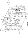
Figure 2 is a front perspective view of an edge encapsulation block according to an embodiment of the present invention; -
Figure 3 is a rear perspective view of the edge encapsulation block shown inFigure 2 ; -
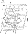
Figure 4 is a perspective view of a first block of the edge encapsulation block shown inFigure 2 -
Figure 5 is a perspective view of a second block of the edge encapsulation block shown inFigure 2 ; -
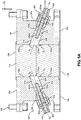
Figure 6A is a top cross-sectional view of the edge encapsulation block shown inFigure 2 in a first configuration; -
Figure 6B is a top cross-sectional view of the edge encapsulation block shown inFigure 2 in a second configuration; -
Figure 7 is a perspective view of a first edge blocker of the edge encapsulation block shown inFigure 2 ; and -
Figure 8 is a perspective view of a second edge blocker of the edge encapsulation block shown inFigure 2 . - An
extrusion system 10 includes anedge encapsulation block 15 that receives a central material and outputs an encapsulated material that can comprise the central material bounded on each lateral side by an edge material. The thickness of the edge material is determined by first andsecond edge blockers edge encapsulation block 15. Certain terminology is used to describe theedge encapsulation block 15 in the following description for convenience only and is not limiting. The words "right," "left," "lower," and "upper" designate directions in the drawings to which reference is made. The words "inner" and "outer" refer to directions toward and away from, respectively, the geometric center of the description to describe theedge encapsulation block 15 and related parts thereof. The words "forward" and "rearward" refer to directions in alongitudinal direction 2 and a direction opposite thelongitudinal direction 2 along theedge encapsulation block 15 and related parts thereof. The terminology includes the above-listed words, derivatives thereof, and words of similar import. - Unless otherwise specified herein, the terms "longitudinal," "lateral," and "vertical" are used to describe the orthogonal directional components of various components of the
edge encapsulation block 15, as designated by thelongitudinal direction 2,lateral direction 4, andvertical direction 6. It should be appreciated that while the longitudinal andlateral directions vertical direction 6 is illustrated as extending along a vertical plane, the planes that encompass the various directions may differ during use. Additionally, thelongitudinal direction 2 may also be referred to as the machine direction. - Embodiments of the present invention include an
edge encapsulation block 15 for applying an edge material to the lateral edges of an extruded central material. Referring toFigure 1 , theedge encapsulation block 15 can be part of anextrusion system 10. Theextrusion system 10 can include a plurality ofextruders coextrusion feed block 14. The materials extruded from theextruders 12a-12c may all be different. Alternatively, some or all of the material extruded from theextruders 12a-12c may be identical. While threeextruders 12a-12c are shown as connected to thecoextrusion feed block 14, thecoextrusion feed block 14 can be alternatively configured to receive material from any number of extruders. Thecoextrusion feed block 14 can combine the individual extrusion flows received from theextruders 12a-12c into a multilayer material that is provided to theedge encapsulation block 15, which then adds an edge material to the lateral edges of the multilayer material to form an encapsulated material, as will be described further below. The edge material can be a reground material comprising waste resin or any other type of inexpensive resin. The edge material can be provided to theedge encapsulation block 15 from anedge material supply 17, which can be an extruder, adhesive melter, or other device capable of supplying a flowable edge material to theedge encapsulation block 15. Theedge encapsulation block 15 then provides the encapsulated material to adie 18, which forms the encapsulated material into a desired product, such as a sheet, web, or coating. Though theextrusion system 10 is depicted as including acoextrusion feed block 14, theextrusion system 10 can alternatively include a monolayer feed block (not shown) that feeds a monolayer material to thecoextrusion feed block 14. -
Figures 2-8 illustrate theedge encapsulation block 15 in detail. With reference toFigures 2-3 , theedge encapsulation block 15 can includes ahousing 16 that has atop surface 16a, abottom surface 16b opposite thetop surface 16a along thevertical direction 6, afront surface 16c, arear surface 16d opposite thefront surface 16c along thelongitudinal direction 2, afirst side surface 16e, and asecond side surface 16f opposite thefirst side surface 16e along thelateral direction 4. Thehousing 16 can comprise afirst block 102 and asecond block 104 releasably coupled to thefirst block 102, such that the first andsecond blocks housing 16. Theedge encapsulation block 15 can include a plurality offasteners 124 that are configured to extend at least partially through the first andsecond blocks first block 102 to thesecond block 104. Thefasteners 124 can be threaded screws, bolts, or any other devices for releasably coupling the first andsecond blocks fasteners 124 are depicted, theedge encapsulation block 15 can comprise any number offasteners 124 as desired. When thefasteners 124 secure thefirst block 102 to thesecond block 104, thefasteners 124 can extend through a plurality ofboreholes 134 defined by thefirst block 102 and a plurality ofboreholes 138 defined by thesecond block 104. Generally, theboreholes second blocks boreholes 134 and/or 138 can optionally be threaded, but can also be unthreaded. Also, it is contemplated that theedge encapsulation block 15 can be defined such that thefasteners 124 are not necessary. For example, the first andsecond blocks second blocks blocks housing 16 of theedge encapsulation block 15 can include more than two separate blocks. Alternatively, thehousing 16 can define a one-piece, monolithic body. Theedge encapsulation block 15 can also include a plurality offasteners 128 that can couple theedge encapsulation block 15 to another part of theextrusion system 10. In one embodiment, thefasteners 128 can couple theedge encapsulation block 15 directly to thedie 18. - The
edge encapsulation block 15 defines acentral extrusion channel 112 that extends through thehousing 16, and thus through the first andsecond blocks longitudinal direction 2. Thecentral extrusion channel 112 can extend from aninlet 106 defined by thefront surface 16c of thehousing 16 to anoutlet 108 defined by therear surface 16d of thehousing 16. Thecentral extrusion channel 112 will be described in more detail below. As previously described, theinlet 106 can receive a multilayer or monolayer material, also referred to as a central material, from thecoextrusion feed block 14 or any other feed block utilized in theextrusion system 10. After the central material passes through thecentral extrusion channel 112, and the encapsulated material is formed from the central material and the edge material, the encapsulated material can be emitted from theoutlet 108 and directed to thedie 18. Though the first andsecond blocks vertical directions housing 16 can be configured such that the first andsecond blocks vertical directions central extrusion channel 112 can extend along the entire length of the intersection between the first andsecond blocks - Continuing with
Figures 2-5 , theedge encapsulation block 15 defines anedge encapsulation channel 120 that is selectively in fluid communication with thecentral extrusion channel 112, as will be described further below. Theedge encapsulation channel 120 extends from aninlet 116 through thehousing 16 to afirst outlet 118a and asecond outlet 118b located interior to thehousing 16. As a result, theedge encapsulation channel 120 can define afirst portion 120a that extends from theinlet 116 to thefirst outlet 118a and asecond portion 120b that extends from theinlet 116 to thesecond outlet 118b. The first andsecond portions edge encapsulation channel 120 can coincide at the portion of theedge encapsulation channel 120 near theinlet 116. Though theinlet 116 is depicted as being defined by thetop surface 16a, theinlet 116 can alternatively be defined by any of thesurfaces 16a-16f of thehousing 16 as desired. Also, although two outlets 18a and 18b are shown, theedge encapsulation channel 120 can alternatively include one or more than two outlets, and likewise more than two portions, as desired. - The
edge encapsulation channel 120 can be partially defined by each of the first andsecond blocks first block 102 can define a firstinner surface 103a that is opposite thefront surface 16c of thehousing 16 along thelongitudinal direction 2, while thesecond block 104 can define a firstinner surface 105a that is opposite therear surface 16d along thelongitudinal direction 2. Thefirst block 102 can define afirst recess 130 that extends into thefirst block 102 from the firstinner surface 103a along thelongitudinal direction 2, while thesecond block 104 can define asecond recess 132 that extends into the second block from the firstinner surface 105a along thelongitudinal direction 2. When the first andsecond blocks housing 16, the firstinner surface 103a of thefirst block 102 engages the firstinner surface 105a of thesecond block 104. Additionally, thefirst recess 130 of thefirst block 102 and thesecond recess 132 of thesecond block 104 substantially align when the first andsecond blocks recesses edge encapsulation channel 120. Additionally, each of therecesses inlet 116 and theoutlets edge encapsulation channel 120. Each of therecesses second blocks edge encapsulation channel 120 formed by therecesses recesses edge encapsulation channel 120 is depicted as being defined by both of the first andsecond blocks edge encapsulation channel 120 can be only partially defined by both of the first andsecond blocks second blocks - The first and
second blocks first edge blocker 200 and asecond edge blocker 300, each of which will be discussed in detail below. Thefirst block 102 can define afirst pocket 142a and asecond pocket 142b spaced from the first pocket along thelateral direction 4. Thefirst pocket 142a is open to both thecentral extrusion channel 112 and theedge encapsulation channel 120, in particular thefirst outlet 118a of theedge encapsulation channel 120. Conversely, thesecond pocket 142b is open to both thecentral extrusion channel 112 and theedge encapsulation channel 120, in particular thesecond outlet 118b of theedge encapsulation channel 120. Likewise, thesecond block 104 can define afirst pocket 146a and asecond pocket 146b spaced from thefirst pocket 146a along thelateral direction 4. Thefirst pocket 146a is open to both thecentral extrusion channel 112 and thefirst outlet 118a of theedge encapsulation channel 120, while thesecond pocket 146b is open to both thecentral extrusion channel 112 and thesecond outlet 118b of theedge encapsulation channel 120. When the first andsecond blocks first pocket 142a of thefirst block 102 aligns with thefirst pocket 146a of thesecond block 104 and thesecond pocket 142b of thefirst block 102 aligns with thesecond pocket 146b of thesecond block 104. As a result, thefirst pockets first edge blocker 200, while thesecond pockets second edge blocker 300. - Continuing with
Figures 6A-7 , afirst edge blocker 200 included in theedge encapsulation block 15 includes amounting block 201 and anactuation shaft 204 that extends through the mountingblock 201. One end of theactuation shaft 204 is coupled to anedge actuator 202 while the other end of theactuation shaft 204 is connected to anedge block 208, such that theedge actuator 202 defines afirst end 204a of thefirst edge blocker 200, while theedge block 208 defines asecond end 204b of thefirst edge blocker 200. Theedge block 208 can define atop surface 210a, abottom surface 210b opposite the top surface along thevertical direction 6, afront surface 210c, arear surface 210d opposite thefront surface 210c along thelongitudinal direction 2, aninner surface 210e, which can also be referred to as the channel surface, and anouter surface 210f opposite theinner surface 210e along thelateral direction 4. Theactuation shaft 204 can extend into theedge block 208 through ablock bore 216 that extends into the edge block 208 from theouter surface 210f and terminates at a location within theedge block 208 that is spaced from theinner surface 210e. The block bore 216 can define an internal threading that is configured to mate with an external threading defined by theactuator shaft 204, such that theedge block 208 and theactuator shaft 204 are threadedly connected. Theedge block 208 can define arecess 212 that extends into the body of theedge block 208 for directing a flow of edge material, as will be described below. In the depicted embodiment, therecess 212 extends into the body of the edge block 208 from thetop surface 310a and therear surface 210d. However, in other embodiments of thefirst edge blocker 200, therecess 212 can extend into the edge block 208 from different ones of thesurfaces 210a-210f as desired. To attach thefirst edge blocker 200 to theedge encapsulation block 15,fasteners 218 extend through the mountingblock 201 and through thefirst side surface 16e of thehousing 16. Thefasteners 218 can be threaded, such that thefasteners 218 releasably couple thefirst edge blocker 200 to thehousing 16. Alternatively, thefasteners 218 can permanently affix thefirst edge blocker 200 to theedge encapsulation block 15. Thefirst edge blocker 200 can also include aseal 222, such as an O-ring, disposed around theactuator shaft 204 at the location theactuator shaft 204 extends through the inner side of the mountingblock 201. Thisseal 222 can prevent edge material from migrating through the mountingblock 201 and exiting theedge encapsulation block 15. - Now referring to
Figures 6A ,6B , and8 , asecond edge blocker 300 that is similar to thefirst edge blocker 200 will be described. Thesecond edge blocker 300 includes amounting block 301 and anactuation shaft 304 that extends through the mountingblock 301. One end of theactuation shaft 304 is coupled to anedge actuator 302 while the other end of theactuation shaft 304 is connected to anedge block 308, such that theedge actuator 302 defines afirst end 304a of theedge blocker 300, while theedge block 308 defines asecond end 304b of theedge blocker 300. Theedge block 308 can define atop surface 310a, abottom surface 310b opposite the top surface along thevertical direction 6, afront surface 310c, arear surface 310d opposite thefront surface 310c along thelongitudinal direction 2, aninner surface 310e, which can also be referred to as the channel surface, and anouter surface 310f opposite theinner surface 310e along thelateral direction 4. Theactuation shaft 304 can extend into theedge block 308 through ablock bore 316 that extends into the edge block 308 from theouter surface 310f and terminates at a location within theedge block 308 that is spaced from theinner surface 310e. The block bore 316 can define an internal threading that is configured to mate with an external threading defined by theactuator shaft 304, such that theedge block 308 and theactuator shaft 304 are threadedly connected. Theedge block 308 can define arecess 312 that extends into the body of theedge block 308 for directing a flow of edge material, as will be described below. In the depicted embodiment, therecess 312 extends into the body of the edge block 308 from thetop surface 310a and therear surface 310d. However, in other embodiments of thesecond edge blocker 300, therecess 312 can extend into the edge block 308 from different ones of thesurfaces 310a-310f as desired. To attach thesecond edge blocker 300 to theedge encapsulation block 15,fasteners 318 extend through the mountingblock 201 and through thesecond side surface 16f of thehousing 16. Thefasteners 318 can be threaded, such that thefasteners 318 releasably couple thesecond edge blocker 300 to thehousing 16. Alternatively, thefasteners 318 can permanently affix thesecond edge blocker 300 to theedge encapsulation block 15. Thesecond edge blocker 300 can also include a seal 322, such as an O-ring, disposed around theactuator shaft 304 at the location theactuator shaft 304 extends through the inner side of the mountingblock 301. This seal 322 can prevent edge material from migrating through the mountingblock 301 and exiting theedge encapsulation block 15. - Continuing with
Figures 6A-6B , thefirst block 102 defines a secondinner surface 103b and a thirdinner surface 103c that is opposite the firstinner surface 105a across thecentral extrusion channel 112 along thelateral direction 4. Similarly, thesecond block 104 defines a secondinner surface 105b and a thirdinner surface 105c opposite the secondinner surface 105b across thecentral extrusion channel 112 along thelateral direction 4. When the first andsecond blocks inner surfaces 130b and 103c of thefirst block 102 and the second and thirdinner surfaces second block 104 partially define thecentral extrusion channel 112. When the first andsecond edge blockers edge encapsulation block 15, theedge block 208 of thefirst edge blocker 200 is received by thefirst pocket 142a of thefirst block 102 and thefirst pocket 146a of thesecond block 104, and theedge block 308 of thesecond edge blocker 300 is received by thesecond pocket 142b of thefirst block 102 and thesecond pocket 146b of thesecond block 104, such that thefirst edge block 208 is spaced from thesecond edge block 308 along thelateral direction 4. Additionally, thechannel surface 210e of theedge block 208 and thechannel surface 310e of theedge block 308 also partially define thecentral extrusion channel 112 when the first andsecond edge blockers housing 16. However, as depicted the first andsecond edge blockers second blocks first edge blocker 200 defines a first axis A1 that extends centrally through the entire length of theactuation shaft 204 and through thecentral extrusion channel 112. The first axis A1 can be angularly offset from the secondinner surface 103b of thesecond block 102 and the secondinner surface 105b of thesecond block 104 by an angle θ1. In the depicted embodiment, the angle θ1 is about 70 degrees. However, in other embodiments, the angle θ1 can be from about 50 degrees to about 90 degrees. Similarly, thesecond edge blocker 300 defines a second axis A2 that extends centrally through the entire length of theactuation shaft 304 and through thecentral extrusion channel 112. The second axis A2 can be angularly offset from the thirdinner surface 103c of thesecond block 102 and the thirdinner surface 105c of thesecond block 104. In the depicted embodiment, the angle θ2 is about 70 degrees. However, in other embodiments, the angle θ2 can be from about 50 degrees to about 90 degrees. Though the angles θ1 and θ2 are depicted as being the same, in other embodiments the angles θ1 and θ2 can be different. - When the first and
second edge blockers second edge blockers Figure 6A , theedge block 208 can extend into the central channel 112 a first distance D1 in a first position, where the first distance D1 is measured as the distance between thechannel surface 210e of theedge block 208 and the secondinner surface 103b of thefirst block 102 along thelateral direction 4. The first distance D1 can also be measured as the distance between thechannel surface 210e of theedge block 208 and the secondinner surface 105b of thesecond block 104 along thelateral direction 4, as the secondinner surfaces second blocks second blocks housing 16. By actuating theedge actuator 202, theedge block 208 translates from the first position to a second position that is spaced from the first position along the first axis A1 that extends through thecentral extrusion channel 112. As a result, in the second position as shown inFigure 6B , theedge block 208 can extend into the central channel 112 a second distance D2 that is different than the first distance D1. The distance D2 can be greater or less than the distance D1. The path theedge block 208 moves along as a result of actuation of theedge actuator 202 is substantially linear, and involves no rotation of theedge block 208. - Likewise, the
edge block 308 can extend into the central channel 112 a third distance D3 in a first position, where the third distance D3 is measured as the distance between thechannel surface 310e of theedge block 308 and the thirdinner surface 103c of thefirst block 102 along thelateral direction 4. The third distance D3 can also be measured as the distance between thechannel surface 310e of theedge block 308 and the thirdinner surface 105c of thesecond block 104 along thelateral direction 4, as the thirdinner surfaces second blocks second blocks housing 16. By actuating theedge actuator 302, theedge block 308 translates from the first position to a second position that is spaced from the first position along the second axis A2 that extends through thecentral extrusion channel 112. As a result, in the second position as shown inFigure 6B , theedge block 308 can extend into the central channel 112 a fourth distance D4 that is different than the third distance D3. The fourth distance D4 can be greater or less than the third distance D3. The path theedge block 308 moves along as a result of actuation of theedge actuator 302 is substantially linear, and involves no rotations of theedge block 308. Though the first and third distances D1 and D3 are depicted as being the same and the second and fourth distances D2 and D4 are depicted as being the same, each of these distances can be different as desired. Additionally, the edge blocks 208 and 308 can be moved such that thechannel surface 210e of theedge block 208 and thechannel surface 310e of theedge block 308 do not extend into thecentral extrusion channel 112. In this configuration, thechannel surface 210e of theedge block 208 is collinear with the secondinner surfaces channel surface 310e of theedge block 308 is collinear with the thirdinner surfaces - To actuate the
edge actuators edge actuators extrusion system 10. Rotation of theedge actuator 202 causes theactuator shaft 204 to rotate, while rotation of theedge actuator 302 causes theactuator shaft 304 to rotate. Because theactuator shaft 204 is threadedly engaged with the threading of the block bore 216, rotation of theactuator shaft 204 causes the threading of theactuator shaft 204 to interact with the threading of the block bore 216 to move theedge block 208 along the first axis A1. Likewise, as theactuator shaft 304 is threadedly engaged with the threading of the block bore 316, rotation of theactuator shaft 304 causes the threading of theactuator shaft 304 to interact with the threading of the block bore 316 to move theedge block 308 along the second axis A2. Each of theedge actuators central extrusion channel 112. For example, one of the edge blocks 208 and 308 can extend into the channel, while thechannel surface central extrusion channel 112. Additionally, in another embodiment, theedge actuators edge actuators extrusion system 10 through a user interface. Further, it is contemplated that theedge actuators edge actuators corresponding actuator shafts edge actuator 202,actuator shaft 204, and edge block 208 of thefirst edge blocker 200 are moved as a unit along the first axis A1, while theedge actuators 302,actuator shaft 304, and edge block 308 of thesecond edge blocker 300 are moved as a unit along the second axis A2. - In operation, the
edge encapsulation block 15 is introduced into theextrusion system 10 by connecting theinlet 106 of thecentral extrusion channel 112 with a coextrusion feed block 14 (or alternatively another type of feed block), theoutlet 108 of thecentral extrusion channel 112 with a die 18, and theinlet 116 of theedge encapsulation channel 120 with anedge material supply 17. Before theextrusion system 10 begins operation, the operator determines the desired thickness of the edge material that will be part of the encapsulated material to be emitted from theoutlet 108 of thecentral extrusion channel 112. To implement the desired thickness, the operator must actuate theedge actuator 202 and/oredge actuator 302 to adjust the distance that theedge block 208 and/oredge block 308 extends into thecentral extrusion channel 112. This distance (for example, first through fourth distances D1-D4 shown inFigures 6A-6B ) represents the thickness of the edge material. The distances that each of the edge blocks 208 and 308 extend into thecentral extrusion channel 112 can be the same or different, depending on the intended encapsulated material to be produced. - Once the first and
second edge blockers extrusion system 10, thus beginning the process of thecoextrusion feed block 14 providing multilayer material to thecentral extrusion channel 112 of theedge encapsulation block 15 through theinlet 106. Concurrently, theedge material supply 17 begins providing edge material to theedge encapsulation channel 120 through theinlet 116. This edge material flows through theedge encapsulation channel 120, which includes splitting the flow of edge material to flow through bothportions first outlet 118a and into therecess 212 of thefirst edge blocker 200, and out of theoutlet 118b and into therecess 312 of thesecond edge blocker 300. Eachrecess central extrusion channel 112. Accordingly, therecess 212 of thefirst edge blocker 200 can be in fluid communication with thefirst outlet 118a of theedge encapsulation channel 120 and thecentral extrusion channel 112, while therecess 312 of thesecond edge blocker 300 can be in fluid communication with thesecond outlet 118b of theedge encapsulation channel 120 and thecentral extrusion channel 112. The amount of edge material that flows through each of therecesses central extrusion channel 112. - Once the central material flows to the portion of the
central extrusion channel 112 where the edge blocks 208 and 308 extend into thecentral extrusion channel 112, the flow of central material is partially obstructed by the edge blocks 208 and 308, particularly the front andchannel surfaces edge block 208 and the first andchannel surfaces edge block 308. This functions to form the central material into its intended final width as part of the encapsulated material. As the central material flows past the rear portion of thechannel surfaces recesses central extrusion channel 112, and comes into contact with the central material. As a result, an encapsulated material is formed comprised of a central material laterally bounded by a thickness of edge material determined by the positions of the edge blocks 208 and 308 relative to thecentral extrusion channel 112. The encapsulated material therefore defines two discrete edges that extend substantially along the machine direction-one edge being between the central material and the edge material on one side of the encapsulated material, and the other edge being between the central material and the edge material on the opposite side of the encapsulated material in thelateral direction 4. The encapsulated material then flows through the remainder of thecentral extrusion channel 112, and out of theoutlet 108 of thecentral extrusion channel 112 to thedie 18. - During operation of the
extrusion system 10, the operator can periodically adjust the positions of the edge blocks 208 and 308 to accommodate new intended encapsulated materials, or to account for a new type of edge material or new type or configuration of central material. The operator can also adjust one of the edge blocks (such as theedge block 208, for example), such that thechannel surface 210e of theedge block 208 is substantially collinear with the secondinner surface 103b of thefirst block 102 and the secondinner surface 105b of thesecond block 104. In this configuration, edge material will only flow through therecess 312 of theedge block 308 and into the central extrusion channel, while edge material will be blocked from flowing into thecentral extrusion channel 112 from therecess 212. The resulting encapsulated material will only include a single layer of edge material on one side. As such, therecesses second portions edge encapsulation channel 120, are both selectively in fluid communication with thecentral extrusion channel 112. In another configuration, both thechannel surface 210e of theedge block 208 is substantially collinear with the secondinner surface 103b of thefirst block 102 and the secondinner surface 105b of thesecond block 104, and thechannel surface 310e of theedge block 308 is substantially collinear with the thirdinner surface 103c of thefirst block 102 and the thirdinner surface 105c of thesecond block 104. In this configuration, edge material will be completely blocked from flowing into thecentral extrusion channel 112. As a result, the resulting encapsulated material will be completely comprised of the central material that enters theedge encapsulation block 15. - The formation of an encapsulated material that includes a central portion defined by extruded material and edge portions defined by an edge material can help reduce waste of costly extruded material during the operation of the product formation process. The edge material can be significantly cheaper than the central material. As a result, should the encapsulated material require trimming, the less expensive edge material will be discarded, rather than the more costly central material. Additionally, should the central material alone have wavy or nonlinear edges after the extrusion process due to not achieving complete solidity, the edge material can bound the central material and provide a defined edge that keeps the central material contained in its intended width and shape.
- Further, the
edge encapsulation block 15 provides several advantages for performing the edge encapsulation operation. The actuation of theedge actuators actuation shafts respective edge actuator housing 16 by including twodifferent blocks housing 16 or replace the first and/orsecond edge blockers - While the invention is described herein using a limited number of embodiments, these specific embodiments are not intended to limit the scope of the invention as otherwise described and claimed herein. The precise arrangement of various elements and order of the steps of articles and methods described herein are not to be considered limiting. For instance, although the steps of the methods are described with reference to sequential series of reference signs and progression of the blocks in the figures, the method can be implemented in a particular order as desired.
- The invention is further described by the following embodiments, wherein:
-
Embodiment 1. An edge encapsulation block, comprising:- a housing that defines 1) a central extrusion channel having an inlet for receiving a central material and an outlet for emitting an encapsulated material that includes the central material and an edge material, and 2) an edge encapsulation channel for receiving the edge material; and
- an edge blocker comprising:
- an edge actuator at a first end of the edge blocker; and
- an edge block at a second end of the edge blocker that is opposite the first end, wherein actuation of the edge actuator causes the edge block to translate from a first position to a second position spaced from the first position along an axis that extends through the central extrusion channel.
-
Embodiment 2. The edge encapsulation block ofEmbodiment 1, wherein the edge encapsulation channel is selectively in fluid communication with the central extrusion channel. - Embodiment 3. The edge encapsulation block of
Embodiment 1, wherein the edge block extends into the central extrusion channel a first distance in the first position and a second distance in the second position, where the second distance is different than the first distance. -
Embodiment 4. The edge encapsulation block of Embodiment 3, wherein the edge blocker is a first edge blocker, the edge actuator is a first edge actuator, the edge block is a first edge block, and the axis is a first axis, the edge encapsulation block further including a second edge blocker comprising:- a second edge actuator at a first end of the second edge blocker; and
- a second edge block at a second end of the second edge blocker that is opposite the first end,
- wherein actuation of the second edge actuator causes the second edge block to translate from a third position to a fourth position spaced from the third position along a second axis that extends through the central extrusion channel.
- Embodiment 5. The edge encapsulation block of
Embodiment 4, wherein the second edge block extends into the central extrusion channel a third distance in the third position that is different than the first and second distances. -
Embodiment 6. The edge encapsulation block ofEmbodiment 4, wherein the inlet of the housing is spaced from the outlet along a machine direction, and the first edge blocker is spaced from the second edge blocker along a lateral direction that is perpendicular to the machine direction. -
Embodiment 7. The edge encapsulation block ofEmbodiment 4, wherein the first edge actuator is capable of actuation independent from the second edge actuator. - Embodiment 8. The edge encapsulation block of
Embodiment 4, wherein the edge encapsulation channel includes an inlet, a first outlet in fluid communication with the first edge block, and a second outlet in fluid communication with the second edge block. - Embodiment 9. The edge encapsulation block of Embodiment 8, wherein the first edge block defines a recess that is in fluid communication with the first outlet and the central extrusion channel, and the second edge block defines a recess that is in fluid communication with the second outlet and the central extrusion channel.
-
Embodiment 10. The edge encapsulation block ofEmbodiment 1, wherein the housing has an inner surface that partially defines the central extrusion channel, and the axis is angularly offset from the inner surface by an angle that is about 70 degrees. - Embodiment 11. The edge encapsulation block of
Embodiment 1, wherein the edge actuator is actuated through rotation. - Embodiment 12. The edge encapsulation block of Embodiment 11, wherein the edge actuator is coupled to an actuator shaft that threadedly engages the edge block.
- Embodiment 13. The edge encapsulation block of
Embodiment 1, wherein the housing includes a first block and a second block releasably coupled to the first block, such that the first and second blocks each partially define the edge encapsulation channel. -
Embodiment 14. The edge encapsulation block ofEmbodiment 1, wherein the edge blocker is releasably coupled to the housing. -
Embodiment 15. The edge encapsulation block ofEmbodiment 1, wherein the central material is a monolayer material. -
Embodiment 16. The edge encapsulation block ofEmbodiment 1, wherein the central material is a multilayer material received from a coextrusion feed block. -
Embodiment 17. The edge encapsulation block ofEmbodiment 1, wherein the inlet of the housing is spaced from the outlet along a machine direction, and the encapsulated material defines an edge that separates the edge material and the central material, wherein the edge extends substantially along the machine direction. -
Embodiment 18. An extrusion system, comprising:- an edge encapsulation block, comprising:
- a housing that defines 1) a central extrusion channel having an inlet for receiving a central material and an outlet for emitting an encapsulated material that includes the central material and an edge material, and 2) an edge encapsulation channel for receiving the edge material; and
- edge blocker comprising:
- an edge actuator; and
- an edge block connected to the edge actuator,
- wherein actuation of the edge actuator causes the edge block to translate from a first position to a second position spaced from the first position along an axis that extends through the central extrusion channel; and
- a die having an inlet for receiving the edge encapsulated material and an outlet for emitting an extruded material.
- an edge encapsulation block, comprising:
-
Embodiment 19. The extrusion system ofEmbodiment 18, wherein the edge block extends into the central extrusion channel a first distance in the first position and a second distance in the second position, where the second distance is different than the first distance. -
Embodiment 20. The extrusion system ofEmbodiment 18, further comprising:
a coextrusion feed block for combining a plurality of extrusion flows to produce the central material, wherein each of the plurality of extrusion flows is received from a respective extruder.
Claims (15)
- An edge encapsulation block, comprising:a housing that defines 1) a central extrusion channel having an inlet for receiving a central material and an outlet for emitting an encapsulated material that includes the central material and an edge material, and 2) an edge encapsulation channel for receiving the edge material; andan edge blocker comprising:an edge actuator at a first end of the edge blocker; andan edge block at a second end of the edge blocker that is opposite the first end,wherein actuation of the edge actuator causes the edge block to translate from a first position to a second position spaced from the first position along an axis that extends through the central extrusion channel.
- The edge encapsulation block of claim 1, wherein the edge encapsulation channel is selectively in fluid communication with the central extrusion channel.
- The edge encapsulation block of claim 1, wherein the edge block extends into the central extrusion channel a first distance in the first position and a second distance in the second position, where the second distance is different than the first distance.
- The edge encapsulation block of claim 3, wherein the edge blocker is a first edge blocker, the edge actuator is a first edge actuator, the edge block is a first edge block, and the axis is a first axis, the edge encapsulation block further including a second edge blocker comprising:a second edge actuator at a first end of the second edge blocker; anda second edge block at a second end of the second edge blocker that is opposite the first end,wherein actuation of the second edge actuator causes the second edge block to translate from a third position to a fourth position spaced from the third position along a second axis that extends through the central extrusion channel.
- The edge encapsulation block of claim 4, wherein the second edge block extends into the central extrusion channel a third distance in the third position that is different than the first and second distances.
- The edge encapsulation block of claim 4, wherein the inlet of the housing is spaced from the outlet along a machine direction, and the first edge blocker is spaced from the second edge blocker along a lateral direction that is perpendicular to the machine direction.
- The edge encapsulation block of claim 4, wherein the first edge actuator is capable of actuation independent from the second edge actuator.
- The edge encapsulation block of claim 4, wherein the edge encapsulation channel includes an inlet, a first outlet in fluid communication with the first edge block, and a second outlet in fluid communication with the second edge block.
- The edge encapsulation block of claim 8, wherein the first edge block defines a recess that is in fluid communication with the first outlet and the central extrusion channel, and the second edge block defines a recess that is in fluid communication with the second outlet and the central extrusion channel.
- The edge encapsulation block of claim 1, wherein the housing has an inner surface that partially defines the central extrusion channel, and the axis is angularly offset from the inner surface by an angle that is about 70 degrees.
- The edge encapsulation block of claim 1, wherein the housing includes a first block and a second block releasably coupled to the first block, such that the first and second blocks each partially define the edge encapsulation channel.
- The edge encapsulation block of claim 1, wherein the edge blocker is releasably coupled to the housing.
- The edge encapsulation block of claim 1, wherein the inlet of the housing is spaced from the outlet along a machine direction, and the encapsulated material defines an edge that separates the edge material and the central material, wherein the edge extends substantially along the machine direction.
- An extrusion system, comprising:the edge encapsulation block of claim 1; anda die having an inlet for receiving the edge encapsulated material and an outlet for emitting an extruded material.
- The extrusion system of claim 14, further comprising:a coextrusion feed block for combining a plurality of extrusion flows to produce the central material, wherein each of the plurality of extrusion flows is received from a respective extruder.
Applications Claiming Priority (1)
| Application Number | Priority Date | Filing Date | Title |
|---|---|---|---|
| US15/716,442 US10974432B2 (en) | 2017-09-26 | 2017-09-26 | Extrusion system including an edge encapsulation block |
Publications (1)
| Publication Number | Publication Date |
|---|---|
| EP3459708A1 true EP3459708A1 (en) | 2019-03-27 |
Family
ID=63683710
Family Applications (1)
| Application Number | Title | Priority Date | Filing Date |
|---|---|---|---|
| EP18196487.5A Withdrawn EP3459708A1 (en) | 2017-09-26 | 2018-09-25 | An extrusion system including an edge encapsulation block |
Country Status (4)
| Country | Link |
|---|---|
| US (1) | US10974432B2 (en) |
| EP (1) | EP3459708A1 (en) |
| JP (1) | JP2019059236A (en) |
| CN (1) | CN109605701A (en) |
Citations (4)
| Publication number | Priority date | Publication date | Assignee | Title |
|---|---|---|---|---|
| US4533510A (en) * | 1983-09-19 | 1985-08-06 | Nissel Frank R | Method and apparatus for continuously co-extruding a sheet |
| EP0642912A1 (en) * | 1993-08-26 | 1995-03-15 | The Cloeren Company | Composite extrusion with width adjustment |
| WO2009016534A2 (en) * | 2007-07-30 | 2009-02-05 | Kimberly-Clark Worldwide, Inc. | Cross directional zoned bicomponent films, film laminates, and systems and method for manufacture of the same |
| JP2009297945A (en) * | 2008-06-11 | 2009-12-24 | Japan Steel Works Ltd:The | Flat die and method for manufacturing sheet |
Family Cites Families (6)
| Publication number | Priority date | Publication date | Assignee | Title |
|---|---|---|---|---|
| US3072962A (en) * | 1960-06-20 | 1963-01-15 | American Viscose Corp | Film extrusion nozzle |
| US4248579A (en) * | 1979-10-10 | 1981-02-03 | Jyohoku Seiko Co., Ltd. | Film extrusion die |
| DE3405257C2 (en) * | 1984-02-15 | 1986-05-22 | Reifenhäuser GmbH & Co Maschinenfabrik, 5210 Troisdorf | Device for the continuous extrusion of a multilayer plastic web |
| US4784815A (en) * | 1987-06-05 | 1988-11-15 | P.C.E. Corp. | Edge-laminating apparatus and process |
| US5375990A (en) * | 1992-09-10 | 1994-12-27 | Extrusion Dies, Inc. | Feed block for coextrusion apparatus |
| US5616350A (en) * | 1995-04-10 | 1997-04-01 | Cincinnati Milacron Inc. | Dual flow divider with diverter valve |
-
2017
- 2017-09-26 US US15/716,442 patent/US10974432B2/en not_active Expired - Fee Related
-
2018
- 2018-09-25 EP EP18196487.5A patent/EP3459708A1/en not_active Withdrawn
- 2018-09-25 CN CN201811119160.2A patent/CN109605701A/en active Pending
- 2018-09-26 JP JP2018179884A patent/JP2019059236A/en active Pending
Patent Citations (4)
| Publication number | Priority date | Publication date | Assignee | Title |
|---|---|---|---|---|
| US4533510A (en) * | 1983-09-19 | 1985-08-06 | Nissel Frank R | Method and apparatus for continuously co-extruding a sheet |
| EP0642912A1 (en) * | 1993-08-26 | 1995-03-15 | The Cloeren Company | Composite extrusion with width adjustment |
| WO2009016534A2 (en) * | 2007-07-30 | 2009-02-05 | Kimberly-Clark Worldwide, Inc. | Cross directional zoned bicomponent films, film laminates, and systems and method for manufacture of the same |
| JP2009297945A (en) * | 2008-06-11 | 2009-12-24 | Japan Steel Works Ltd:The | Flat die and method for manufacturing sheet |
Also Published As
| Publication number | Publication date |
|---|---|
| US10974432B2 (en) | 2021-04-13 |
| CN109605701A (en) | 2019-04-12 |
| JP2019059236A (en) | 2019-04-18 |
| US20190091912A1 (en) | 2019-03-28 |
Similar Documents
| Publication | Publication Date | Title |
|---|---|---|
| EP2979840B1 (en) | Coextrusion feedblock, coextrusion profiling insert assembly, and methods of operation | |
| US3761211A (en) | Multi-layer extrusion apparatus | |
| US4197069A (en) | Variable thickness extrusion die | |
| US4152387A (en) | Method for forming multi-layer laminates | |
| EP2310191B1 (en) | Method and apparatus for producing composite structures | |
| EP0201617B1 (en) | Method and apparatus for continuously co-extruding a sheet | |
| US5711349A (en) | Flow divider with diverter valve | |
| EP3216583B1 (en) | Coextrusion adapter | |
| EP2862693A1 (en) | Coextrusion feedblock and coextrusion profiling insert assembly | |
| EP0353064B1 (en) | Method and apparatus for feeding a plurality of molten resin jet streams into T die | |
| EP2949448B1 (en) | Multi-manifold extrusion die with deckle system and method of using same | |
| US10974432B2 (en) | Extrusion system including an edge encapsulation block | |
| WO2005023516A1 (en) | Extrusion molding apparatus for resin tube | |
| JPH0326517A (en) | Manufacture and device for multi-layer molded product | |
| EP3299142A1 (en) | Coextrusion feedblock | |
| KR100818833B1 (en) | Extrusion molding apparatus for resin multi-layer tube | |
| CN115970987B (en) | Extrusion coating dies and coating machines | |
| KR100961056B1 (en) | Resin sheet manufacturing method and apparatus | |
| EP3674070B1 (en) | Rubber extrusion device and method for manufacturing rubber extruded object | |
| JP3774207B2 (en) | Manufacturing method and manufacturing apparatus for long shaped product | |
| US5971736A (en) | Device for joining at least two material flows in a laminar coextrusion machine | |
| EP3418013B1 (en) | Method for applying inserts in a panel or a similar element | |
| DE19802646C1 (en) | Multilayer plastic strip manufacture with low thickness variation across width by combining streams for outer layers before they are widened for combining with central layer | |
| CN103448229B (en) | The distributor of sheet extruder | |
| EP1941986A4 (en) | Die for film-blowing machine and the machine including such die |
Legal Events
| Date | Code | Title | Description |
|---|---|---|---|
| PUAI | Public reference made under article 153(3) epc to a published international application that has entered the european phase |
Free format text: ORIGINAL CODE: 0009012 |
|
| STAA | Information on the status of an ep patent application or granted ep patent |
Free format text: STATUS: THE APPLICATION HAS BEEN PUBLISHED |
|
| AK | Designated contracting states |
Kind code of ref document: A1 Designated state(s): AL AT BE BG CH CY CZ DE DK EE ES FI FR GB GR HR HU IE IS IT LI LT LU LV MC MK MT NL NO PL PT RO RS SE SI SK SM TR |
|
| AX | Request for extension of the european patent |
Extension state: BA ME |
|
| STAA | Information on the status of an ep patent application or granted ep patent |
Free format text: STATUS: REQUEST FOR EXAMINATION WAS MADE |
|
| 17P | Request for examination filed |
Effective date: 20190927 |
|
| RBV | Designated contracting states (corrected) |
Designated state(s): AL AT BE BG CH CY CZ DE DK EE ES FI FR GB GR HR HU IE IS IT LI LT LU LV MC MK MT NL NO PL PT RO RS SE SI SK SM TR |
|
| STAA | Information on the status of an ep patent application or granted ep patent |
Free format text: STATUS: EXAMINATION IS IN PROGRESS |
|
| 17Q | First examination report despatched |
Effective date: 20210409 |
|
| STAA | Information on the status of an ep patent application or granted ep patent |
Free format text: STATUS: THE APPLICATION IS DEEMED TO BE WITHDRAWN |
|
| 18D | Application deemed to be withdrawn |
Effective date: 20210820 |