EP3459669B1 - Schweissstromquelle mit verbesserter funktionsrobustheit - Google Patents
Schweissstromquelle mit verbesserter funktionsrobustheit Download PDFInfo
- Publication number
- EP3459669B1 EP3459669B1 EP18192381.4A EP18192381A EP3459669B1 EP 3459669 B1 EP3459669 B1 EP 3459669B1 EP 18192381 A EP18192381 A EP 18192381A EP 3459669 B1 EP3459669 B1 EP 3459669B1
- Authority
- EP
- European Patent Office
- Prior art keywords
- human
- computing unit
- power source
- welding
- welding power
- Prior art date
- Legal status (The legal status is an assumption and is not a legal conclusion. Google has not performed a legal analysis and makes no representation as to the accuracy of the status listed.)
- Active
Links
Images
Classifications
-
- B—PERFORMING OPERATIONS; TRANSPORTING
- B23—MACHINE TOOLS; METAL-WORKING NOT OTHERWISE PROVIDED FOR
- B23K—SOLDERING OR UNSOLDERING; WELDING; CLADDING OR PLATING BY SOLDERING OR WELDING; CUTTING BY APPLYING HEAT LOCALLY, e.g. FLAME CUTTING; WORKING BY LASER BEAM
- B23K9/00—Arc welding or cutting
- B23K9/32—Accessories
-
- B—PERFORMING OPERATIONS; TRANSPORTING
- B23—MACHINE TOOLS; METAL-WORKING NOT OTHERWISE PROVIDED FOR
- B23K—SOLDERING OR UNSOLDERING; WELDING; CLADDING OR PLATING BY SOLDERING OR WELDING; CUTTING BY APPLYING HEAT LOCALLY, e.g. FLAME CUTTING; WORKING BY LASER BEAM
- B23K9/00—Arc welding or cutting
- B23K9/10—Other electric circuits therefor; Protective circuits; Remote controls
- B23K9/1006—Power supply
-
- B—PERFORMING OPERATIONS; TRANSPORTING
- B23—MACHINE TOOLS; METAL-WORKING NOT OTHERWISE PROVIDED FOR
- B23K—SOLDERING OR UNSOLDERING; WELDING; CLADDING OR PLATING BY SOLDERING OR WELDING; CUTTING BY APPLYING HEAT LOCALLY, e.g. FLAME CUTTING; WORKING BY LASER BEAM
- B23K9/00—Arc welding or cutting
- B23K9/10—Other electric circuits therefor; Protective circuits; Remote controls
- B23K9/1006—Power supply
- B23K9/1043—Power supply characterised by the electric circuit
- B23K9/1056—Power supply characterised by the electric circuit by using digital means
- B23K9/1062—Power supply characterised by the electric circuit by using digital means with computing means
-
- B—PERFORMING OPERATIONS; TRANSPORTING
- B23—MACHINE TOOLS; METAL-WORKING NOT OTHERWISE PROVIDED FOR
- B23K—SOLDERING OR UNSOLDERING; WELDING; CLADDING OR PLATING BY SOLDERING OR WELDING; CUTTING BY APPLYING HEAT LOCALLY, e.g. FLAME CUTTING; WORKING BY LASER BEAM
- B23K9/00—Arc welding or cutting
- B23K9/095—Monitoring or automatic control of welding parameters
- B23K9/0953—Monitoring or automatic control of welding parameters using computing means
-
- G—PHYSICS
- G06—COMPUTING OR CALCULATING; COUNTING
- G06F—ELECTRIC DIGITAL DATA PROCESSING
- G06F3/00—Input arrangements for transferring data to be processed into a form capable of being handled by the computer; Output arrangements for transferring data from processing unit to output unit, e.g. interface arrangements
- G06F3/01—Input arrangements or combined input and output arrangements for interaction between user and computer
- G06F3/048—Interaction techniques based on graphical user interfaces [GUI]
- G06F3/0487—Interaction techniques based on graphical user interfaces [GUI] using specific features provided by the input device, e.g. functions controlled by the rotation of a mouse with dual sensing arrangements, or of the nature of the input device, e.g. tap gestures based on pressure sensed by a digitiser
- G06F3/0488—Interaction techniques based on graphical user interfaces [GUI] using specific features provided by the input device, e.g. functions controlled by the rotation of a mouse with dual sensing arrangements, or of the nature of the input device, e.g. tap gestures based on pressure sensed by a digitiser using a touch-screen or digitiser, e.g. input of commands through traced gestures
Definitions
- the invention relates to a welding power source, comprising a housing made of metallic material, a welding inverter, a digital, electronic welding process computing unit and a human-machine interface device (see, for example, WO 2014/039878 , which forms the preamble of claim 1). It is preferably a welding power source for orbital welding devices. Such welding power sources are well known in the prior art.
- the object of the present invention is to improve these disadvantages.
- the task is solved by independent claim 1.
- a separate second computing unit is used, which is better shielded from the field-generating welding units by the housing and which directly controls the human-machine interface.
- a housing formed from a metallic material is preferably understood to mean that at least one housing wall is formed from a metallic material as a partition between the welding process computing unit/welding inverter and the human-machine computing unit/human-machine interface device.
- the housing is preferably made of metallic material on several sides, preferably all sides.
- a digital, electronic computing unit or digital computer is preferably understood to mean primarily independent, electronic computer hardware. It preferably has a CPU, RAM, an internal system bus and a network interface.
- a human-machine interface device is understood to be a hardware component that is set up to convert a user's input into digital signals (e.g. mouse, keyboard, touchpad or screen) and/or to output digital signals into signals that can be perceived by a user (e.g. display), and/or which has a connection point (e.g. USB socket), which makes it possible to make digital signals available to a user on a memory that can be decoupled from the welding power source.
- digital signals e.g. mouse, keyboard, touchpad or screen
- connection point e.g. USB socket
- the human-machine interface device is preferably connected to the human-machine computing unit via the internal system bus of the human-machine computing unit and thus preferably forms part of the human-machine computing unit.
- a computer network is preferably understood to be an association of various technical, primarily independent electronic digital computing units, which enables the individual digital electronic computing units to communicate with each other.
- the communication connection is a fieldbus connection, preferably a CAN bus connection. This further increases the robustness.
- the human-machine computing unit and the welding process computing unit are galvanically separated from one another by means of one or more optocouplers/optocouplers or inductive couplers/inductive couplers. This further increases the robustness.
- the welding power source has a mains voltage input and both the human-machine computing unit and the welding process computing unit are supplied with power via the mains voltage input.
- the human-machine computing unit and the human-machine interface device are held together on a movable, preferably pivotable, flap mounted on the housing, the flap being between an open position in which the human-machine interface Interface device can be used by a user, and a closed position in which the Human-machine interface device, preferably covered by the flap and the housing, is movable.
- the human-machine interface device has one or more of the following devices: USB socket, RJ45 socket, HDMI socket, touchscreen, touchpad, keyboard, mouse, printer.
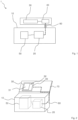
- FIG. 1 shows a welding power source 1 having a housing 10 made of metallic material, a welding inverter 50, a digital, electronic welding process computing unit 20 and a human-machine interface device 30.
- the welding process computing unit 20 is set up to control the welding inverter 50.
- the welding process computing unit 20 and the welding inverter 50 are arranged in the housing 10 and the human-machine interface device 30 is attached to the welding power source 1 outside the housing 10.
- the welding power source 1 additionally has a digital, electronic man-machine computing unit 40, which is attached to the welding power source 1 outside the housing 10.
- the human-machine interface device 30 is connected to the human-machine computing unit 40 and the human-machine computing unit 40 and the welding process computing unit 20 are networked with one another via a communication connection 60 and form a computer network.
- FIG. 2 is a welding power source 1 with the elements of the welding power source FIG. 1 shown.
- the Communication connection 60 a Can-Bus fieldbus connection.
- the human-machine computing unit 40 and the human-machine interface device 30 are held together on a flap 70 which is pivotably mounted on the housing 10.
- the flap 70 is movable between an open position in which the human-machine interface device 30 is usable by a user and a closed position in which the human-machine interface device 30 is covered by the flap 70 and the housing 10 .
- the human-machine interface device 30 has a USB socket 32 and a touchscreen 31.
Landscapes
- Engineering & Computer Science (AREA)
- Physics & Mathematics (AREA)
- Plasma & Fusion (AREA)
- Mechanical Engineering (AREA)
- Theoretical Computer Science (AREA)
- Arc Welding Control (AREA)
- Inverter Devices (AREA)
- Generation Of Surge Voltage And Current (AREA)
Description
- Die Erfindung betrifft eine Schweißstromquelle, aufweisend ein aus metallischem Werkstoff gebildetes Gehäuse, einen Schweißinverter, eine digitale, elektronische Schweißprozess-Recheneinheit und eine Mensch-Maschine-Schnittstelleneinhchung (siehe, z.B.,
WO 2014/039878 , welche den Oberbegriff des Anspruchs 1 bildet). Es handelt sich bevorzugt um eine Schweißstromquelle für Orbitalschweißvorrichtungen. Derartige Schweißstromquellen sind im Stand der Technik hinlänglich bekannt. - Die Erfinder befanden diese insofern als nachteilig, als dass zeitweise Funktionsstörungen im Bereich von Mensch-Maschine-Schnittstelleneinrichtungen auftreten. Aufgabe der vorliegenden Erfindung ist es, diese Nachteile zu verbessern. Die Aufgabe wird durch den unabhängigen Anspruch 1 gelöst.
- Vorteilhafte Weiterbildungen sind in den Unteransprüchen definiert.
- Erfindungsgemäß wird die Aufgabe gelöst durch eine Schweißstromquelle aufweisend ein aus metallischem Werkstoff gebildetes Gehäuse, einen Schweißinverter, eine digitale, elektronische Schweißprozess-Recheneinheit und eine Mensch-Maschine-Schnittstelleneinrichtung,
- wobei die Schweißprozess-Recheneinheit eingerichtet ist, den Schweißinverter anzusteuern,
- wobei die Schweißprozess-Recheneinheit und der Schweißinverter in dem Gehäuse angeordnet sind und die Mensch-Maschine-Schnittstelleneinrichtung außerhalb des Gehäuses an der Schweißstromquelle befestigt ist, wobei die Schweißstromquelle zusätzlich eine digitale, elektronische Mensch-Maschine-Recheneinheit aufweist, welche außerhalb des Gehäuses an der Schweißstromquelle befestigt ist, und wobei die Mensch-Maschine-Schnittstelleneinrichtung an die Mensch-Maschine-Recheneinheit angeschlossen ist, und wobei die Mensch-Maschine-Recheneinheit und die Schweißprozess-Recheneinheit über eine Kommunikationsverbindung, z.B. Busverbindung oder Ethernet, miteinander vernetzt sind und ein Rechnernetz bilden.
- Hierdurch wird die Fehleranfälligkeit der Schweißstromquelle verringert. Die Erfinder haben herausgefunden, dass durch die beim Schweißen entstehenden elektromagnetischen Felder Mensch-Maschine-Schnittstellenfunktionen zumindest zeitweise fehlerhaft sind. Zur Lösung des Problems wird erfindungsgemäß eine separate zweite Recheneinheit verwendet, welche durch das Gehäuse besser abgeschirmt von den felderzeugenden schweißtechnischen Einheiten ist und welche die Mensch-Maschine-Schnittstelle direkt ansteuert.
- Unter einem aus metallischem Werkstoff gebildeten Gehäuse wird bevorzugt verstanden, dass zumindest eine Gehäusewand als eine Trennwand zwischen Schweißprozess-Recheneinheit / Schweißinverter und Mensch-Maschine-Recheneinheit / Mensch-Maschine-Schnittstelleneinrichtung aus metallischem Werkstoff gebildet ist. Bevorzugt ist das Gehäuse an mehreren Seiten, bevorzugt allen Seiten aus metallischem Werkstoff gebildet.
- Unter einer digitalen, elektronischen Recheneinheit bzw. digitalem Computer wird bevorzugt eine primär selbstständige, elektronische Rechnerhardware verstanden. Sie weist bevorzugt eine CPU, Arbeitsspeicher, einen internen System-Bus sowie eine Netzwerkschnittstelle auf.
- Unter einer Mensch-Maschine-Schnittstelleneinrichtung wird eine Hardwarekomponente verstanden, welche eingerichtet ist, Eingaben eines Benutzers in digitale Signale zu wandeln (z.B. Mouse, Tastatur, Touchpad- oder -screen) und/oder digitale Signale in für einen Benutzer wahrnehmbare Signale zu auszugeben (z.B. Display), und/oder welche einen Anschlusspunkt (z.B. USB-Buchse) aufweist, welcher ermöglicht, digitale Signale für einen Benutzer auf einem von der Schweißstromquelle abkoppelbaren Speicher zur Verfügung zu stellen.
- Die Mensch-Maschine-Schnittstelleneinrichtung ist bevorzugt über den internen System-Bus der Mensch-Maschine-Recheneinheit an die Mensch-Maschine-Recheneinheit angebunden und bildet somit bevorzugt einen Teil der Mensch-Maschine-Recheneinheit.
- Unter einem Rechnernetz wird bevorzugt ein Zusammenschluss verschiedener technischer, primär selbstständiger elektronischer digital elektronischer Recheneinheiten verstanden, der die Kommunikation der einzelnen digital elektronischen Recheneinheiten untereinander ermöglicht.
- Erfindungsgemäß ist die Kommunikationsverbindung eine Feldbus-Verbindung, bevorzugt eine CAN-BusVerbindung. Hierdurch wird die Robustheit weiter erhöht.
- Erfindungsgemäß sind die Mensch-Maschine-Recheneinheit und die Schweißprozess-Recheneinheit mittels eines/mehrerer Optokopplers/Optokoppler oder Induktivkopplers / Induktivkoppler galvanisch voneinander getrennt. Hierdurch wird die Robustheit weiter erhöht.
- In einem weiteren Ausführungsbeispiel der vorliegenden Erfindung weist die Schweißstromquelle einen Netzspannungseingang auf und sowohl die Mensch-Maschine-Recheneinheit als auch die Schweißprozess-Recheneinheit werden über den Netzspannungseingang mit Strom gespeist.
- Hierdurch wird der einfache Anschlussvorgang der Schweißstromquelle an die Netzstromversorgung trotz zweier Recheneinheiten beibehalten.
- In einem weiteren Ausführungsbeispiel der vorliegenden Erfindung sind die Mensch-Maschine-Recheneinheit und die Mensch-Maschine-Schnittstelleneinrichtung zusammen an einer bewegbar, bevorzugt schwenkbar, am Gehäuse gelagerten Klappe gehalten, wobei die Klappe zwischen einer offenen Stellung, in welcher die Mensch-Maschine-Schnittstelleneinrichtung durch einen Benutzer benutzbar ist, und einer geschlossenen Stellung, in welcher die Mensch-Maschine-Schnittstelleneinrichtung, bevorzugt durch die Klappe und das Gehäuse, verdeckt ist, bewegbar ist.
- Hierdurch ist eine intuitive Bedienung bei gleichzeitig platzsparender Anordnung möglich, die mit geschlossener Klappe ausreichenden Transportschutz bietet.
- In einem weiteren Ausführungsbeispiel der vorliegenden Erfindung weist die Mensch-Maschine-Schnittstelleneinrichtung eine oder mehrere der folgenden Einrichtungen auf: USB-Buchse, RJ45-Buchse, HDMI-Buchse, Touchscreen, Touchpad, Tastatur, Mouse, Drucker.
- Die Erfindung soll nun anhand von Zeichnungen beispielhaft weiter veranschaulicht werden. Hierbei zeigen:
- FIG. 1
- ein schematisches Diagramm einer ersten erfindungsgemäßen Schweißstromquelle;
- FIG. 2
- eine perspektivische Ansicht einer zweiten erfindungsgemäßen Schweißstromquelle.
-
FIG. 1 zeigt eine Schweißstromquelle 1 aufweisend ein aus metallischem Werkstoff gebildetes Gehäuse 10, einen Schweißinverter 50, eine digitale, elektronische Schweißprozess-Recheneinheit 20 und eine Mensch-Maschine-Schnittstelleneinrichtung 30. Die Schweißprozess-Recheneinheit 20 ist eingerichtet ist, den Schweißinverter 50 anzusteuern. Die Schweißprozess-Recheneinheit 20 und der Schweißinverter 50 sind in dem Gehäuse 10 angeordnet und die Mensch-Maschine-Schnittstelleneinrichtung 30 ist außerhalb des Gehäuses 10 an der Schweißstromquelle 1 befestigt. Die Schweißstromquelle 1 weist zusätzlich eine digitale, elektronische Mensch-Maschine-Recheneinheit 40 auf, welche außerhalb des Gehäuses 10 an der Schweißstromquelle 1 befestigt ist. Die Mensch-Maschine-Schnittstelleneinrichtung 30 ist an die Mensch-Maschine-Recheneinheit 40 angeschlossen und die Mensch-Maschine-Recheneinheit 40 und die Schweißprozess-Recheneinheit 20 sind über eine Kommunikationsverbindung 60 miteinander vernetzt und bilden ein Rechnernetz. - In
FIG. 2 ist eine Schweißstromquelle 1 mit den Elementen der Schweißstromquelle ausFIG. 1 gezeigt. Zusätzlich ist die Kommunikationsverbindung 60 eine Can-Bus Feldbus-Verbindung. Die Mensch-Maschine-Recheneinheit 40 und die Mensch-Maschine-Schnittstelleneinrichtung 30 sind zusammen an einer schwenkbar am Gehäuse 10 gelagerten Klappe 70 gehalten. Die Klappe 70 ist zwischen einer offenen Stellung, in welcher die Mensch-Maschine-Schnittstelleneinrichtung 30 durch einen Benutzer benutzbar ist, und einer geschlossenen Stellung, in welcher die Mensch-Maschine-Schnittstelleneinrichtung 30 durch die Klappe 70 und das Gehäuse 10 verdeckt ist, bewegbar. Die Mensch-Maschine-Schnittstelleneinrichtung 30 weist eine USB-Buchse 32 und einen Touchscreen 31 auf. -
- 1
- Schweißstromquelle
- 10
- Gehäuse
- 20
- Schweißprozess-Recheneinheit
- 30
- Mensch-Maschine-Schnittstelleneinrichtung
- 31
- Touchscreen
- 32
- USB-Buchse
- 40
- Mensch-Maschine-Recheneinheit
- 50
- Schweißinverter
- 60
- Kommunikationsverbindung
- 70
- Klappe
Claims (4)
- Schweißstromquelle (1) aufweisend:- ein aus metallischem Werkstoff gebildetes Gehäuse (10),- einen Schweißinverter (50),- eine digitale, elektronische Schweißprozess-Recheneinheit (20) und- eine Mensch-Maschine-Schnittstelleneinrichtung (30),die Schweißstromquelle (1) ist dadurch charakterisiert, dasswobei die Schweißprozess-Recheneinheit (20) eingerichtet ist, den Schweißinverter (50) anzusteuern,wobei die Schweißprozess-Recheneinheit (20) und der Schweißinverter (50) in dem Gehäuse (10) angeordnet sind und die Mensch-Maschine-Schnittstelleneinrichtung (30) außerhalb des Gehäuses (10) an der Schweißstromquelle (1) befestigt ist,wobei die Schweißstromquelle (1) zusätzlich eine digitale, elektronische Mensch-Maschine-Recheneinheit (40) aufweist, welche außerhalb des Gehäuses (10) an der Schweißstromquelle (1) befestigt ist, und wobei die Mensch-Maschine-Schnittstelleneinrichtung (30) an die Mensch-Maschine-Recheneinheit (40) angeschlossen ist, und wobei die Mensch-Maschine-Recheneinheit (40) und die Schweißprozess-Recheneinheit (20) über eine Kommunikationsverbindung (60) miteinander vernetzt sind und ein Rechnernetz bilden,die Mensch-Maschine-Recheneinheit (40) und die Schweißprozess-Recheneinheit (20) mittels eines/mehrerer Optokopplers/Optokoppler oder Induktivkopplers/Induktivkoppler galvanisch voneinander getrennt sind, unddie Kommunikationsverbindung (60) eine Feldbus-Verbindung ist.
- Schweißstromquelle (1) gemäß Anspruch 1, wobei die Schweißstromquelle (1) einen Netzspannungseingang (50) aufweist und wobei sowohl die Mensch-Maschine-Recheneinheit (40) als auch die Schweißprozess-Recheneinheit (20) über den Netzspannungseingang (50) mit Strom gespeist werden.
- Schweißstromquelle (1) gemäß einem der vorhergehenden Ansprüche, wobei die Mensch-Maschine-Recheneinheit (40) und die Mensch-Maschine-Schnittstelleneinrichtung (30) zusammen an einer bewegbar am Gehäuse (10) gelagerten Klappe (70) gehalten sind, und wobei die Klappe (70) zwischen einer offenen Stellung, in welcher die Mensch-Maschine-Schnittstelleneinrichtung (30) durch einen Benutzer benutzbar ist, und einer geschlossenen Stellung, in welcher die Mensch-Maschine-Schnittstelleneinrichtung (30) verdeckt ist, bewegbar ist.
- Schweißstromquelle (1) gemäß einem der vorhergehenden Ansprüche, wobei die Mensch-Maschine-Schnittstelleneinrichtung (30) eine oder mehrere der folgenden Einrichtungen aufweist: USB-Buchse (32), RJ45-Buchse, HDMI-Buchse, Touchscreen (31), Touchpad, Tastatur, Mouse, Drucker.
Applications Claiming Priority (1)
| Application Number | Priority Date | Filing Date | Title |
|---|---|---|---|
| DE102017122068.2A DE102017122068A1 (de) | 2017-09-22 | 2017-09-22 | Schweißstromquelle mit verbesserter Funktionsrobustheit |
Publications (2)
| Publication Number | Publication Date |
|---|---|
| EP3459669A1 EP3459669A1 (de) | 2019-03-27 |
| EP3459669B1 true EP3459669B1 (de) | 2024-02-28 |
Family
ID=63491460
Family Applications (1)
| Application Number | Title | Priority Date | Filing Date |
|---|---|---|---|
| EP18192381.4A Active EP3459669B1 (de) | 2017-09-22 | 2018-09-04 | Schweissstromquelle mit verbesserter funktionsrobustheit |
Country Status (4)
| Country | Link |
|---|---|
| US (1) | US10953485B2 (de) |
| EP (1) | EP3459669B1 (de) |
| CN (1) | CN109530863A (de) |
| DE (1) | DE102017122068A1 (de) |
Family Cites Families (9)
| Publication number | Priority date | Publication date | Assignee | Title |
|---|---|---|---|---|
| JP2002321056A (ja) * | 2001-04-25 | 2002-11-05 | Obara Corp | 溶接制御装置 |
| CN201147925Y (zh) * | 2007-12-20 | 2008-11-12 | 北京中鼎盛华环境科技发展有限公司 | 机器人操作系统 |
| DE102007062387A1 (de) * | 2007-12-22 | 2009-06-25 | Robert Bosch Gmbh | Verfahren zum Übertragen von Feldbus-Daten sowie Feldbus-Kommunikationssystem |
| US10328514B2 (en) * | 2011-11-07 | 2019-06-25 | Lincoln Global, Inc. | Use of mobile communications devices as user interface for welding equipment and systems |
| US10682720B2 (en) * | 2012-09-07 | 2020-06-16 | Illinois Tool Works Inc. | Welding systems and devices having a configurable personal computer user interface |
| US20150268748A1 (en) * | 2014-03-20 | 2015-09-24 | Shenzhen Lexyz Technology Co., Ltd. | Interactive control and display method and system |
| FR3033130B1 (fr) * | 2015-02-27 | 2018-03-23 | L'oreal | Dispositif cosmetique a compartiments etanches |
| DE102015105702B3 (de) * | 2015-04-14 | 2016-08-04 | Beckhoff Automation Gmbh | Bussystem mit einem Einspeisemodul und einem Verbrauchermodul |
| CN206432698U (zh) * | 2017-02-14 | 2017-08-22 | 珠海西格电力科技有限公司 | 一种自供电智能保护装置 |
-
2017
- 2017-09-22 DE DE102017122068.2A patent/DE102017122068A1/de not_active Ceased
-
2018
- 2018-09-04 EP EP18192381.4A patent/EP3459669B1/de active Active
- 2018-09-18 CN CN201811088145.6A patent/CN109530863A/zh active Pending
- 2018-09-20 US US16/136,853 patent/US10953485B2/en active Active
Also Published As
| Publication number | Publication date |
|---|---|
| US20190091793A1 (en) | 2019-03-28 |
| US10953485B2 (en) | 2021-03-23 |
| DE102017122068A1 (de) | 2019-03-28 |
| CN109530863A (zh) | 2019-03-29 |
| EP3459669A1 (de) | 2019-03-27 |
Similar Documents
| Publication | Publication Date | Title |
|---|---|---|
| EP2017869B1 (de) | Sicherheitsvorrichtung zum mehrkanaligen Steuern einer sicherheitstechnischen Einrichtung | |
| DE102009054155A1 (de) | Ein- und/oder Ausgabe-Sicherheitsmodul für ein Automatisierungsgerät | |
| DE112014006323T5 (de) | SPS-Einheit und speicherprogrammierbare Steuerung | |
| AT14695U1 (de) | Serielles Bussystem mit Koppelmodulen | |
| EP2246756A1 (de) | Verfahren und Bediengerät zum Bedienen einer sicherheitsgerichteten industriellen Automatisierungskomponente | |
| EP1589386B1 (de) | Prozesssteuerung | |
| EP1431877A2 (de) | Parametrier-/Diagnosesystem für Feldgeräte | |
| WO2007096126A1 (de) | Sicherheitskonzept für eine getriebestellvorrichtung | |
| EP3418833A1 (de) | Verfahren und anordnung zum zugriff eines ersten computers auf eine virtuelle maschine eines zweiten computers | |
| EP3688958B1 (de) | System und verfahren zum geschützten übertragen von daten | |
| EP3669240B1 (de) | Redundante prozesssteuerung | |
| EP3459669A1 (de) | Schweissstromquelle mit verbesserter funktionsrobustheit | |
| DE102007007537A1 (de) | Leitsystem einer technischen Anlage | |
| DE102018219878B3 (de) | Steuereinheit für eine medizinische Bildgebungsanlage mit einem Prozessor und einem Logikgatter; Bildgebungsanlage sowie Verfahren zum Steuern einer medizinischen Bildgebungsanlage | |
| EP1646919A1 (de) | Kopplungsvorrichtung für drei bussysteme | |
| DE102013112816A1 (de) | Sicherheitssteuerung | |
| DE102011115318B4 (de) | Flugsteuerungssystem | |
| DE102016116152A1 (de) | Elektrisches Gerät mit einer Funktionseinrichtung | |
| EP2249217A1 (de) | Automatisierungsgerät und Automatisierungssystem | |
| DE202018104502U1 (de) | Stromversorgungs-Kommunikationsvorrichtung für Grafikkarten | |
| DE102005007477B4 (de) | Programmierbare Steuerung zur Maschinen-und/oder Anlagenautomatisierung mit Standard-Steuerungs- und Sicherheitsfunktionen und Kommunikation mit einer Sicherheits-EA sowie Verfahren zum Betrieb der programmierbaren Steuerung | |
| EP3646313B1 (de) | Verfahren und vorrichtung zur ausgabe von bilddaten für eine sichere anzeige | |
| DE102019209009A1 (de) | Filter, Anordnung und Betriebsverfahren für eine Anordnung | |
| DE10215121A1 (de) | Verfahren zum Projektieren und/oder Betreiben einer Automatisierungseinrichtung | |
| DE102019127551A1 (de) | Multifunktionaler Switch zum Einsatz in einer prozesssteuernden Automatisierungsanlage sowie eine solche prozesssteuernde Automatisierungsanlage |
Legal Events
| Date | Code | Title | Description |
|---|---|---|---|
| PUAI | Public reference made under article 153(3) epc to a published international application that has entered the european phase |
Free format text: ORIGINAL CODE: 0009012 |
|
| STAA | Information on the status of an ep patent application or granted ep patent |
Free format text: STATUS: REQUEST FOR EXAMINATION WAS MADE |
|
| 17P | Request for examination filed |
Effective date: 20180904 |
|
| AK | Designated contracting states |
Kind code of ref document: A1 Designated state(s): AL AT BE BG CH CY CZ DE DK EE ES FI FR GB GR HR HU IE IS IT LI LT LU LV MC MK MT NL NO PL PT RO RS SE SI SK SM TR |
|
| AX | Request for extension of the european patent |
Extension state: BA ME |
|
| STAA | Information on the status of an ep patent application or granted ep patent |
Free format text: STATUS: EXAMINATION IS IN PROGRESS |
|
| 17Q | First examination report despatched |
Effective date: 20210127 |
|
| GRAP | Despatch of communication of intention to grant a patent |
Free format text: ORIGINAL CODE: EPIDOSNIGR1 |
|
| STAA | Information on the status of an ep patent application or granted ep patent |
Free format text: STATUS: GRANT OF PATENT IS INTENDED |
|
| INTG | Intention to grant announced |
Effective date: 20231130 |
|
| GRAS | Grant fee paid |
Free format text: ORIGINAL CODE: EPIDOSNIGR3 |
|
| GRAA | (expected) grant |
Free format text: ORIGINAL CODE: 0009210 |
|
| STAA | Information on the status of an ep patent application or granted ep patent |
Free format text: STATUS: THE PATENT HAS BEEN GRANTED |
|
| AK | Designated contracting states |
Kind code of ref document: B1 Designated state(s): AL AT BE BG CH CY CZ DE DK EE ES FI FR GB GR HR HU IE IS IT LI LT LU LV MC MK MT NL NO PL PT RO RS SE SI SK SM TR |
|
| REG | Reference to a national code |
Ref country code: GB Ref legal event code: FG4D Free format text: NOT ENGLISH |
|
| REG | Reference to a national code |
Ref country code: CH Ref legal event code: EP |
|
| REG | Reference to a national code |
Ref country code: DE Ref legal event code: R096 Ref document number: 502018014165 Country of ref document: DE |
|
| REG | Reference to a national code |
Ref country code: IE Ref legal event code: FG4D Free format text: LANGUAGE OF EP DOCUMENT: GERMAN |
|
| P01 | Opt-out of the competence of the unified patent court (upc) registered |
Effective date: 20240307 |
|
| REG | Reference to a national code |
Ref country code: LT Ref legal event code: MG9D |
|
| PG25 | Lapsed in a contracting state [announced via postgrant information from national office to epo] |
Ref country code: IS Free format text: LAPSE BECAUSE OF FAILURE TO SUBMIT A TRANSLATION OF THE DESCRIPTION OR TO PAY THE FEE WITHIN THE PRESCRIBED TIME-LIMIT Effective date: 20240628 |
|
| REG | Reference to a national code |
Ref country code: NL Ref legal event code: MP Effective date: 20240228 |
|
| PG25 | Lapsed in a contracting state [announced via postgrant information from national office to epo] |
Ref country code: LT Free format text: LAPSE BECAUSE OF FAILURE TO SUBMIT A TRANSLATION OF THE DESCRIPTION OR TO PAY THE FEE WITHIN THE PRESCRIBED TIME-LIMIT Effective date: 20240228 |
|
| PG25 | Lapsed in a contracting state [announced via postgrant information from national office to epo] |
Ref country code: GR Free format text: LAPSE BECAUSE OF FAILURE TO SUBMIT A TRANSLATION OF THE DESCRIPTION OR TO PAY THE FEE WITHIN THE PRESCRIBED TIME-LIMIT Effective date: 20240529 |
|
| PG25 | Lapsed in a contracting state [announced via postgrant information from national office to epo] |
Ref country code: RS Free format text: LAPSE BECAUSE OF FAILURE TO SUBMIT A TRANSLATION OF THE DESCRIPTION OR TO PAY THE FEE WITHIN THE PRESCRIBED TIME-LIMIT Effective date: 20240528 Ref country code: HR Free format text: LAPSE BECAUSE OF FAILURE TO SUBMIT A TRANSLATION OF THE DESCRIPTION OR TO PAY THE FEE WITHIN THE PRESCRIBED TIME-LIMIT Effective date: 20240228 Ref country code: NL Free format text: LAPSE BECAUSE OF FAILURE TO SUBMIT A TRANSLATION OF THE DESCRIPTION OR TO PAY THE FEE WITHIN THE PRESCRIBED TIME-LIMIT Effective date: 20240228 |
|
| PG25 | Lapsed in a contracting state [announced via postgrant information from national office to epo] |
Ref country code: ES Free format text: LAPSE BECAUSE OF FAILURE TO SUBMIT A TRANSLATION OF THE DESCRIPTION OR TO PAY THE FEE WITHIN THE PRESCRIBED TIME-LIMIT Effective date: 20240228 |
|
| PG25 | Lapsed in a contracting state [announced via postgrant information from national office to epo] |
Ref country code: RS Free format text: LAPSE BECAUSE OF FAILURE TO SUBMIT A TRANSLATION OF THE DESCRIPTION OR TO PAY THE FEE WITHIN THE PRESCRIBED TIME-LIMIT Effective date: 20240528 Ref country code: NO Free format text: LAPSE BECAUSE OF FAILURE TO SUBMIT A TRANSLATION OF THE DESCRIPTION OR TO PAY THE FEE WITHIN THE PRESCRIBED TIME-LIMIT Effective date: 20240528 Ref country code: NL Free format text: LAPSE BECAUSE OF FAILURE TO SUBMIT A TRANSLATION OF THE DESCRIPTION OR TO PAY THE FEE WITHIN THE PRESCRIBED TIME-LIMIT Effective date: 20240228 Ref country code: LT Free format text: LAPSE BECAUSE OF FAILURE TO SUBMIT A TRANSLATION OF THE DESCRIPTION OR TO PAY THE FEE WITHIN THE PRESCRIBED TIME-LIMIT Effective date: 20240228 Ref country code: IS Free format text: LAPSE BECAUSE OF FAILURE TO SUBMIT A TRANSLATION OF THE DESCRIPTION OR TO PAY THE FEE WITHIN THE PRESCRIBED TIME-LIMIT Effective date: 20240628 Ref country code: HR Free format text: LAPSE BECAUSE OF FAILURE TO SUBMIT A TRANSLATION OF THE DESCRIPTION OR TO PAY THE FEE WITHIN THE PRESCRIBED TIME-LIMIT Effective date: 20240228 Ref country code: GR Free format text: LAPSE BECAUSE OF FAILURE TO SUBMIT A TRANSLATION OF THE DESCRIPTION OR TO PAY THE FEE WITHIN THE PRESCRIBED TIME-LIMIT Effective date: 20240529 Ref country code: FI Free format text: LAPSE BECAUSE OF FAILURE TO SUBMIT A TRANSLATION OF THE DESCRIPTION OR TO PAY THE FEE WITHIN THE PRESCRIBED TIME-LIMIT Effective date: 20240228 Ref country code: ES Free format text: LAPSE BECAUSE OF FAILURE TO SUBMIT A TRANSLATION OF THE DESCRIPTION OR TO PAY THE FEE WITHIN THE PRESCRIBED TIME-LIMIT Effective date: 20240228 Ref country code: BG Free format text: LAPSE BECAUSE OF FAILURE TO SUBMIT A TRANSLATION OF THE DESCRIPTION OR TO PAY THE FEE WITHIN THE PRESCRIBED TIME-LIMIT Effective date: 20240228 |
|
| PG25 | Lapsed in a contracting state [announced via postgrant information from national office to epo] |
Ref country code: PT Free format text: LAPSE BECAUSE OF FAILURE TO SUBMIT A TRANSLATION OF THE DESCRIPTION OR TO PAY THE FEE WITHIN THE PRESCRIBED TIME-LIMIT Effective date: 20240628 Ref country code: PL Free format text: LAPSE BECAUSE OF FAILURE TO SUBMIT A TRANSLATION OF THE DESCRIPTION OR TO PAY THE FEE WITHIN THE PRESCRIBED TIME-LIMIT Effective date: 20240228 |
|
| PG25 | Lapsed in a contracting state [announced via postgrant information from national office to epo] |
Ref country code: SE Free format text: LAPSE BECAUSE OF FAILURE TO SUBMIT A TRANSLATION OF THE DESCRIPTION OR TO PAY THE FEE WITHIN THE PRESCRIBED TIME-LIMIT Effective date: 20240228 Ref country code: PT Free format text: LAPSE BECAUSE OF FAILURE TO SUBMIT A TRANSLATION OF THE DESCRIPTION OR TO PAY THE FEE WITHIN THE PRESCRIBED TIME-LIMIT Effective date: 20240628 Ref country code: PL Free format text: LAPSE BECAUSE OF FAILURE TO SUBMIT A TRANSLATION OF THE DESCRIPTION OR TO PAY THE FEE WITHIN THE PRESCRIBED TIME-LIMIT Effective date: 20240228 Ref country code: LV Free format text: LAPSE BECAUSE OF FAILURE TO SUBMIT A TRANSLATION OF THE DESCRIPTION OR TO PAY THE FEE WITHIN THE PRESCRIBED TIME-LIMIT Effective date: 20240228 |
|
| PG25 | Lapsed in a contracting state [announced via postgrant information from national office to epo] |
Ref country code: DK Free format text: LAPSE BECAUSE OF FAILURE TO SUBMIT A TRANSLATION OF THE DESCRIPTION OR TO PAY THE FEE WITHIN THE PRESCRIBED TIME-LIMIT Effective date: 20240228 |
|
| PG25 | Lapsed in a contracting state [announced via postgrant information from national office to epo] |
Ref country code: SM Free format text: LAPSE BECAUSE OF FAILURE TO SUBMIT A TRANSLATION OF THE DESCRIPTION OR TO PAY THE FEE WITHIN THE PRESCRIBED TIME-LIMIT Effective date: 20240228 |
|
| PG25 | Lapsed in a contracting state [announced via postgrant information from national office to epo] |
Ref country code: CZ Free format text: LAPSE BECAUSE OF FAILURE TO SUBMIT A TRANSLATION OF THE DESCRIPTION OR TO PAY THE FEE WITHIN THE PRESCRIBED TIME-LIMIT Effective date: 20240228 Ref country code: EE Free format text: LAPSE BECAUSE OF FAILURE TO SUBMIT A TRANSLATION OF THE DESCRIPTION OR TO PAY THE FEE WITHIN THE PRESCRIBED TIME-LIMIT Effective date: 20240228 |
|
| PG25 | Lapsed in a contracting state [announced via postgrant information from national office to epo] |
Ref country code: SK Free format text: LAPSE BECAUSE OF FAILURE TO SUBMIT A TRANSLATION OF THE DESCRIPTION OR TO PAY THE FEE WITHIN THE PRESCRIBED TIME-LIMIT Effective date: 20240228 |
|
| PG25 | Lapsed in a contracting state [announced via postgrant information from national office to epo] |
Ref country code: SM Free format text: LAPSE BECAUSE OF FAILURE TO SUBMIT A TRANSLATION OF THE DESCRIPTION OR TO PAY THE FEE WITHIN THE PRESCRIBED TIME-LIMIT Effective date: 20240228 Ref country code: SK Free format text: LAPSE BECAUSE OF FAILURE TO SUBMIT A TRANSLATION OF THE DESCRIPTION OR TO PAY THE FEE WITHIN THE PRESCRIBED TIME-LIMIT Effective date: 20240228 Ref country code: RO Free format text: LAPSE BECAUSE OF FAILURE TO SUBMIT A TRANSLATION OF THE DESCRIPTION OR TO PAY THE FEE WITHIN THE PRESCRIBED TIME-LIMIT Effective date: 20240228 Ref country code: EE Free format text: LAPSE BECAUSE OF FAILURE TO SUBMIT A TRANSLATION OF THE DESCRIPTION OR TO PAY THE FEE WITHIN THE PRESCRIBED TIME-LIMIT Effective date: 20240228 Ref country code: DK Free format text: LAPSE BECAUSE OF FAILURE TO SUBMIT A TRANSLATION OF THE DESCRIPTION OR TO PAY THE FEE WITHIN THE PRESCRIBED TIME-LIMIT Effective date: 20240228 Ref country code: CZ Free format text: LAPSE BECAUSE OF FAILURE TO SUBMIT A TRANSLATION OF THE DESCRIPTION OR TO PAY THE FEE WITHIN THE PRESCRIBED TIME-LIMIT Effective date: 20240228 |
|
| REG | Reference to a national code |
Ref country code: DE Ref legal event code: R097 Ref document number: 502018014165 Country of ref document: DE |
|
| PG25 | Lapsed in a contracting state [announced via postgrant information from national office to epo] |
Ref country code: IT Free format text: LAPSE BECAUSE OF FAILURE TO SUBMIT A TRANSLATION OF THE DESCRIPTION OR TO PAY THE FEE WITHIN THE PRESCRIBED TIME-LIMIT Effective date: 20240228 |
|
| PG25 | Lapsed in a contracting state [announced via postgrant information from national office to epo] |
Ref country code: IT Free format text: LAPSE BECAUSE OF FAILURE TO SUBMIT A TRANSLATION OF THE DESCRIPTION OR TO PAY THE FEE WITHIN THE PRESCRIBED TIME-LIMIT Effective date: 20240228 |
|
| PLBE | No opposition filed within time limit |
Free format text: ORIGINAL CODE: 0009261 |
|
| STAA | Information on the status of an ep patent application or granted ep patent |
Free format text: STATUS: NO OPPOSITION FILED WITHIN TIME LIMIT |
|
| 26N | No opposition filed |
Effective date: 20241129 |
|
| PG25 | Lapsed in a contracting state [announced via postgrant information from national office to epo] |
Ref country code: SI Free format text: LAPSE BECAUSE OF FAILURE TO SUBMIT A TRANSLATION OF THE DESCRIPTION OR TO PAY THE FEE WITHIN THE PRESCRIBED TIME-LIMIT Effective date: 20240228 Ref country code: MC Free format text: LAPSE BECAUSE OF FAILURE TO SUBMIT A TRANSLATION OF THE DESCRIPTION OR TO PAY THE FEE WITHIN THE PRESCRIBED TIME-LIMIT Effective date: 20240228 |
|
| REG | Reference to a national code |
Ref country code: CH Ref legal event code: PL |
|
| PG25 | Lapsed in a contracting state [announced via postgrant information from national office to epo] |
Ref country code: LU Free format text: LAPSE BECAUSE OF NON-PAYMENT OF DUE FEES Effective date: 20240904 |
|
| GBPC | Gb: european patent ceased through non-payment of renewal fee |
Effective date: 20240904 |
|
| PG25 | Lapsed in a contracting state [announced via postgrant information from national office to epo] |
Ref country code: GB Free format text: LAPSE BECAUSE OF NON-PAYMENT OF DUE FEES Effective date: 20240904 |
|
| REG | Reference to a national code |
Ref country code: BE Ref legal event code: MM Effective date: 20240930 |
|
| PG25 | Lapsed in a contracting state [announced via postgrant information from national office to epo] |
Ref country code: BE Free format text: LAPSE BECAUSE OF NON-PAYMENT OF DUE FEES Effective date: 20240930 |
|
| PG25 | Lapsed in a contracting state [announced via postgrant information from national office to epo] |
Ref country code: CH Free format text: LAPSE BECAUSE OF NON-PAYMENT OF DUE FEES Effective date: 20240930 |
|
| PGFP | Annual fee paid to national office [announced via postgrant information from national office to epo] |
Ref country code: DE Payment date: 20250929 Year of fee payment: 8 |
|
| PGFP | Annual fee paid to national office [announced via postgrant information from national office to epo] |
Ref country code: FR Payment date: 20250925 Year of fee payment: 8 |
|
| PGFP | Annual fee paid to national office [announced via postgrant information from national office to epo] |
Ref country code: IE Payment date: 20250929 Year of fee payment: 8 |
|
| REG | Reference to a national code |
Ref country code: AT Ref legal event code: MM01 Ref document number: 1660803 Country of ref document: AT Kind code of ref document: T Effective date: 20240904 |
|
| PG25 | Lapsed in a contracting state [announced via postgrant information from national office to epo] |
Ref country code: AT Free format text: LAPSE BECAUSE OF NON-PAYMENT OF DUE FEES Effective date: 20240904 |
|
| PG25 | Lapsed in a contracting state [announced via postgrant information from national office to epo] |
Ref country code: CY Free format text: LAPSE BECAUSE OF FAILURE TO SUBMIT A TRANSLATION OF THE DESCRIPTION OR TO PAY THE FEE WITHIN THE PRESCRIBED TIME-LIMIT; INVALID AB INITIO Effective date: 20180904 |
|
| PG25 | Lapsed in a contracting state [announced via postgrant information from national office to epo] |
Ref country code: HU Free format text: LAPSE BECAUSE OF FAILURE TO SUBMIT A TRANSLATION OF THE DESCRIPTION OR TO PAY THE FEE WITHIN THE PRESCRIBED TIME-LIMIT; INVALID AB INITIO Effective date: 20180904 |