EP3459335A1 - Windrow chute with independently movable chute sections - Google Patents
Windrow chute with independently movable chute sections Download PDFInfo
- Publication number
- EP3459335A1 EP3459335A1 EP18194920.7A EP18194920A EP3459335A1 EP 3459335 A1 EP3459335 A1 EP 3459335A1 EP 18194920 A EP18194920 A EP 18194920A EP 3459335 A1 EP3459335 A1 EP 3459335A1
- Authority
- EP
- European Patent Office
- Prior art keywords
- chute
- section
- windrow
- axis
- chute section
- Prior art date
- Legal status (The legal status is an assumption and is not a legal conclusion. Google has not performed a legal analysis and makes no representation as to the accuracy of the status listed.)
- Granted
Links
Images






Classifications
-
- B—PERFORMING OPERATIONS; TRANSPORTING
- B65—CONVEYING; PACKING; STORING; HANDLING THIN OR FILAMENTARY MATERIAL
- B65G—TRANSPORT OR STORAGE DEVICES, e.g. CONVEYORS FOR LOADING OR TIPPING, SHOP CONVEYOR SYSTEMS OR PNEUMATIC TUBE CONVEYORS
- B65G11/00—Chutes
- B65G11/12—Chutes pivotable
- B65G11/126—Chutes pivotable for bulk
-
- A—HUMAN NECESSITIES
- A01—AGRICULTURE; FORESTRY; ANIMAL HUSBANDRY; HUNTING; TRAPPING; FISHING
- A01D—HARVESTING; MOWING
- A01D41/00—Combines, i.e. harvesters or mowers combined with threshing devices
- A01D41/12—Details of combines
- A01D41/1243—Devices for laying-out or distributing the straw
-
- B—PERFORMING OPERATIONS; TRANSPORTING
- B65—CONVEYING; PACKING; STORING; HANDLING THIN OR FILAMENTARY MATERIAL
- B65G—TRANSPORT OR STORAGE DEVICES, e.g. CONVEYORS FOR LOADING OR TIPPING, SHOP CONVEYOR SYSTEMS OR PNEUMATIC TUBE CONVEYORS
- B65G2201/00—Indexing codes relating to handling devices, e.g. conveyors, characterised by the type of product or load being conveyed or handled
- B65G2201/04—Bulk
Definitions
- the present disclosure relates generally to residue handling systems in agricultural harvesters, and more particularly to a windrow chute with independently movable sections that can be adjusted to different positions during operation of a harvester to control the placement and spacing of windrows.
- An agricultural vehicle known as a harvester "combine” can perform multiple harvesting functions, including picking, threshing, separating and cleaning of grain.
- a combine includes a header which removes the crop from a field, and a feeder housing which transports the crop matter into the combine for further processing. During this processing, grain is separated from crop residue.
- the crop residue such as straw, is discharged from the rear of the combine. In many cases, the crop residue is deposited back onto the field in the form of windrows at the back of the combine. The windrows can then be collected by balers or other machinery, after which the collected material can be fed to livestock or used for other purposes.
- Windrow material is typically discharged through a chute at the rear of the combine and deposited on the field.
- the material is often deposited in a generally straight line along the center line of the combine, or in close proximity to the center line. Given the width of the combine, the resulting windrows are spaced relatively far apart from one another. This is not always desirable, because many balers can only collect one windrow per pass when the windrows are spaced far apart.
- the width of the windrow i.e. the cross dimension of the windrow perpendicular to the direction of movement of the combine.
- Wider windrows allow crop residue with a higher moisture content to dry more quickly on the field, because the crop residue is deposited in a thinner layer and spread over more area.
- a narrower windrow may be more desirable so that the material can be easily picked up with a baler without having to first rake the material into narrower rows.
- many conventional windrow chutes lack the ability to adjust the width of windrows because the chutes have fixed geometries.
- windrow chute may briefly accelerate as the rear end of the combine executes the turn, causing crop residue to exit the chute at a higher velocity, spread out over a wide swath, form an irregularly-shaped path, and/or penetrate below the stubble. These conditions can make it more difficult to collect the crop residue at the end of the windrow.
- a windrow chute assembly for an agricultural vehicle can include a chute body comprising a plurality of movable chute sections.
- the plurality of movable chute sections can include a first chute section and a second chute section.
- the first chute section can have a first proximal end for receiving material from the agricultural vehicle, a first distal end opposite the first proximal end for discharging material from the agricultural vehicle, and a first chute axis extending between the first proximal end and the first distal end.
- the second chute section can have a second proximal end for receiving material from the agricultural vehicle, a second distal end opposite the second proximal end for discharging material from the agricultural vehicle, and a second chute axis extending between the second proximal end and the second distal end.
- the first proximal end of the first chute section and the second proximal end of the second chute section can define a transverse axis therebetween.
- the first chute section can be displaceable so as to define a first angle of displacement between the first chute axis and the transverse axis
- the second chute section can be displaceable so as to define a second angle of displacement between the second chute axis and the transverse axis.
- the first chute section and the second chute section can be displaceable toward one another to a closed configuration, in which a sum of the first angle of displacement and the second angle of displacement is a maximum, and displaceable away from one another to an open configuration, in which the sum of the first angle of displacement and the second angle of displacement is a minimum.
- first chute section can be pivotally mountable on a first pivot axis
- second chute section can be pivotally mountable on a second pivot axis offset from the first pivot axis
- first pivot axis can be parallel to the second pivot axis.
- first pivot axis and the second pivot axis can be perpendicular to the transverse axis.
- first pivot axis and the second pivot axis can be vertical axes.
- first chute section can be displaceable through an angle greater than ninety degrees relative to the transverse axis
- second chute section can be displaceable through an angle greater than ninety degrees relative to the transverse axis
- the sum of the first angle of displacement and the second angle of displacement can be 180 degrees when the first chute section and the second chute section are in the closed configuration.
- the sum of the first angle of displacement and the second angle of displacement can be less than 0 degrees when the first chute section and the second chute section are in the open configuration.
- the windrow chute assembly can define a center axis that extends perpendicularly to the transverse axis at a point equidistant from the first proximal end of the first chute section and the second proximal end of the second chute section.
- first chute section and the second chute section can each be pivotable toward the center axis to assume a zero position.
- first chute axis can be parallel to the second chute axis in the zero position.
- first chute axis can intersect the second chute axis in the closed configuration.
- first chute section and the second chute section can be movable to the closed configuration at a zero position in which the first chute axis and the second chute axis are parallel to the center axis.
- first chute section and the second chute section can be movable to the closed configuration at a left bias position in which the first angle of displacement is less than ninety degrees and the second angle of displacement is greater than ninety degrees.
- first chute section and the second chute section can be movable to the closed configuration at a right bias position in which the first angle of displacement is greater than ninety degrees and the second angle of displacement is less than ninety degrees.
- first chute section can include a first bottom wall section and the second chute section can include a second bottom wall section, the first bottom wall section and the second bottom wall section configured to convey material out of the first chute section and the second chute section, respectively.
- first chute section can include a first sidewall and the second chute section can include a second sidewall.
- first bottom wall section can overlap the second bottom wall section in the closed configuration.
- first chute section and the second chute section can form an open channel in the closed configuration.
- first chute section and the second chute section can form a closed conduit in the closed configuration.
- FIG. 1 illustrates a simplified, side view of one embodiment of an agricultural combine 10.
- the combine 10 may be configured the same as or similar to any suitable agricultural combine known in the art, such as a conventional style combine or axial combine.
- the combine 10 can include an axially arranged threshing system 12 and a cleaning system.
- the threshing system 12 may include one or more cylindrical rotors 14 rotatably supported within a cage or concave 16 for conveying a flow of crop material in a helical flow path along a circumferential space 18 defined between the rotor 14 and the concave.
- the crop e.g., grain, legumes, and/or the like
- the crop residue e.g., husks, pods and/or the like
- the crop residue may continue along the helical path and may be subsequently discharged through a discharge opening (not shown) defined at a downstream end 22 of the threshing system 12.
- Combine 10 also includes a crop residue discharge system 24 for expelling crop residue from the combine to the field.
- Discharge system 24 includes a spreader 42 for evenly distributing the residue across the harvest width.
- discharge system 24 includes an opening 46 near the rear of the combine for windrowing.
- a windrow chute assembly100 is mounted to a frame 47 on the rear of combine 10 just beneath opening 46.
- Windrow chute assembly 100 is shown in more detail.
- Windrow chute assembly 100 is mounted to frame 47 and projects rearwardly from combine 10.
- a pivotable door 49 extends adjacent frame 47 and is operable in one of two positions to control how crop residue is discharged to the field.
- Door 49 can be pivoted to a closed position which allows crop residue to enter spreader 42, in which case the material is spread across the width of the cut.
- door 49 can be pivoted to an open position to bypass spreader 42 and direct crop residue to windrow chute assembly 100 for depositing the material onto the field in windrows.
- Windrow chute assembly 100 includes a chute body 110.
- Chute body 110 includes a floor plate 112 having a generally triangular configuration as shown.
- Chute body 110 also includes a plurality of chute sections that are independently movable.
- Windrow chute assemblies can include any number of movable chute sections.
- chute body 110 includes a first chute section 120 and a second chute section 130.
- first chute section 120 and second chute section 130 are not necessarily illustrated in correct proportion to the other parts of combine 10.
- the illustrated dimensions of first chute section 120 and second chute section 130 including but not limited to their respective length, width and depth, are not to scale, and the actual dimensions could be much greater or much less than the dimensions as shown.
- the length of first chute section 120 and the length of second chute section 130 could be several times larger than that shown.
- First chute section 120 has a first proximal end 122 for receiving material from combine 10, and a first distal end 124 opposite the first proximal end for discharging material from the combine. First chute section 120 also defines a first chute axis 126 that extends between first proximal end 122 and first distal end 124 as shown. Second chute section 130 has a second proximal end 132 for receiving material from combine 10, a second distal end 134 opposite the second proximal end for discharging material from the combine. Second chute section 130 also defines a second chute axis 136 extending between second proximal end 132 and second distal end 134 as shown.
- Floor plate 112 has a first side 114 and a second side 116 opposite the first side.
- First proximal end 122 of first chute section 120 is movably mounted to first side 114
- second proximal end 132 of second chute section 130 is movably mounted to second side 116.
- Chute sections can be mounted to frames or floor plates in a variety of ways that allow the chute sections to move either independently or in unison.
- first proximal end 122 of first chute section 120 is pivotably mounted to first side 114 with a first pivot joint 128.
- second proximal end 132 of second chute section 130 is pivotably mounted to second side 116 with a second pivot joint 138.
- first chute section 120 is pivotally mounted on a first pivot axis 129 that passes through first pivot joint 128.
- second chute section 130 is pivotally mounted on a second pivot axis 139 that passes through second pivot joint 138.
- Second pivot axis 139 is parallel to and offset from first pivot axis 138.
- Pivot joints can take various forms, including but not limited to pin connections.
- first pivot joint 128 and second pivot joint 138 include pins 113 that pass through bores that extend through the first and second chute sections 120, 130 and floor plate 112.
- a transverse axis 140 is defined between first proximal end 122 of first chute section 120 and second proximal end 132 of second chute section 130. More specifically, transverse axis 140 intersects and extends between first pivot joint 128 and second pivot joint 138 as shown. Transverse axis 140 is perpendicular to the direction of forward travel T of combine 10. First pivot axis 129 and second pivot axis 139 are vertical axes that intersect transverse axis 140 and are perpendicular to the transverse axis.
- a center axis 150 extends perpendicularly to transverse axis 140. Center axis 150 extends through a point P on transverse axis 140 that is equidistant from first pivot axis 129 and second pivot axis 139.
- First chute section 120 and second chute section 130 are pivotably displaceable, independently of one another, and can assume an infinite number of positions and configurations relative to transverse axis 140.
- first chute section 120 and second chute section 130 can be pivotably adjusted to a closed configuration to deposit crop residue onto the field in a narrow windrow.
- First chute section 120 and second chute section 130 can also be pivotably adjusted to a partially closed configuration to deposit crop residue onto the field in a wider windrow than in the closed configuration.
- the cross sectional shape and width of each windrow can be controlled by selecting a closed configuration or a partially closed configuration that corresponds to the desired windrow shape and width.
- first chute section 120 and second chute section 130 can be pivotably adjusted to an open position, in which the first and second chute sections are moved outwardly and away from center axis 150, and toward the sides of the combine, where they do not obstruct the rear area of the combine.
- This ability to move the chute sections to the sides allows personnel standing on the ground to reach areas on the rear of the combine.
- personnel can manually pivot the chute sections to the open position to reach items such as access handles and ladders that are pulled down to access the engine compartment.
- First chute section 120 is pivotably displaceable relative to floor plate 112 so as to define a first angle of displacement ⁇ 1 between first chute axis 126 and transverse axis 140.
- second chute section 130 is pivotably displaceable relative to floor plate 112 so as to define a second angle of displacement ⁇ 2 between second chute axis 136 and transverse axis 140.
- first chute section 120 and second chute section 130 can be pivotably adjusted to various angles relative to transverse axis 140 to control the position of each windrow relative to the center line of combine 10.
- first and second chute sections 120 and 130 can be pivoted to the left to deposit the windrow on a left side of the combine's center line, or to the right to deposit the windrow on a right side of the combine's center line.
- Chute sections can be designed to abut one another in the closed configuration.
- chute sections can be designed to partially overlap one another in the closed configuration.
- first chute section 120 and second chute section 130 partially overlap when in the closed configuration.
- the extent of overlap varies depending on the relative orientations of first and second chute sections 120 and 130 when they are in a closed configuration.
- First and second chute sections 120 and 130 can assume an infinite number of positions when in the closed configuration. These positions fall into one of three general categories, namely, a "zero" position, a "left-bias” position, and a "right-bias” position, as will be explained.
- first chute section 120 and second chute section 130 are pivoted toward one another in a closed configuration in which the chute sections are in the zero position.
- first chute section 120 and second chute section 130 are oriented such that chute body 110 discharges crop residue directly behind combine 10 on a line coinciding with the center line of the combine.
- First chute section 120 is pivoted inwardly 90 degrees relative to transverse axis 140, such that ⁇ 1 is equal to 90 degrees.
- second chute section 130 is pivoted inwardly 90 degrees relative to transverse axis 140, such that ⁇ 2 is equal to 90 degrees.
- First chute axis 126 and second chute axis 136 are parallel to one another and to center axis 150. The sum of ⁇ 1 and ⁇ 2 is equal to 180 degrees.
- first chute section 120 and second chute section 130 are shown in another closed configuration, with the chute sections pivoted to a left-bias position.
- first chute section 120 and second chute section 130 are oriented such that the chute body 110 discharges crop residue on a line offset to the left of the center line of combine 10.
- the term "left” refers to the left side of the center line when facing the rear of the combine.
- First chute section 120 and second chute section 130 can be sufficiently long to deposit the windrow at any desired distance from the center line, including a distance beyond the left tire track of combine 10. With the windrow placed outside of the tire tracks, a grain cart and tractor of equal width following directly behind combine 10 does not have to straddle the windrow while receiving grain from the combine.
- First chute section 120 is pivoted inwardly approximately 65 degrees relative to transverse axis 140, such that ⁇ 1 is equal to 65 degrees.
- Second chute section 130 is pivoted inwardly 125 degrees relative to transverse axis 140, such that ⁇ 2 is equal to 125 degrees.
- first chute section 120 overlaps second chute section 130.
- first chute axis 126 and second chute axis 136 are not parallel to one another.
- the sum of ⁇ 1 and ⁇ 2 is equal to 190 degrees.
- first chute section 120 and second chute section 130 are shown in another closed configuration, with the chute sections pivoted to a right-bias position.
- first chute section 120 and second chute section 130 are oriented such that the chute body 110 discharges crop residue on a line offset to the right of the center line of combine 10.
- the term "right” refers to the right side of the center line when facing the rear of the combine.
- First chute section 120 and second chute section 130 can be sufficiently long to deposit the windrow at any desired distance from the center line, including a distance beyond the right tire track of combine 10. With the windrow placed outside of the tire tracks, a grain cart and tractor of equal width following directly behind combine 10 does not have to straddle the windrow, as noted above.
- First chute section 120 is pivoted inwardly approximately 125 degrees relative to transverse axis 140, such that ⁇ 1 is equal to 125 degrees.
- Second chute section 130 is pivoted inwardly 65 degrees relative to transverse axis 140, such that ⁇ 2 is equal to 65 degrees.
- first chute section 120 overlaps second chute section 130.
- first chute axis 126 and second chute axis 136 are not parallel to one another.
- the sum of ⁇ 1 and ⁇ 2 is equal to 190 degrees.
- Windrow chute assembly 100 can be pivoted to a closed configuration and remain fixed in that configuration during a windrow operation, with ⁇ 1 and ⁇ 2 remaining fixed (static mode).
- windrow chute assembly 100 can pivot in a closed configuration during a windrow operation, with ⁇ 1 and ⁇ 2 changing in response to operating conditions (dynamic mode).
- windrow chute assembly 100 can operate in the static mode, with the first and second chute sections in the zero position, as the combine is in the middle of a long windrow.
- windrow chute assembly 100 can switch to a dynamic mode, in which the first and second chute sections gradually pivot toward a left-bias or right-bias configuration.
- the windrow is discharged to the ground more smoothly than would be the case if the chute sections remain in the zero position, because the windrow is discharged along a curve that more closely to conforms to the shape of the arc through which the chute sections travel during the turn
- the direction of bias When operating in a dynamic mode, the direction of bias will be the same direction as the turning direction.
- the operator can steer the first and second windrow chute sections from the zero position to the right-bias position during the turn. In the right-bias position, the chute sections are more tangential to the arc of the turn than in the zero position, which allows the windrow to be dropped more smoothly along an arc at the end of the windrow. The reverse would be done during a left turn.
- the operator can compensate for the changing orientation of the combine to maintain a smooth trajectory for the material being discharged. This results in a neater windrow at the end of each pass.
- the windrow chute If the windrow chute is kept in the zero position during the turn, the windrow will be discharged in a radially outward direction with respect to the arc shaped direction of travel, rather than tangentially. Straw that is discharged radially outwardly from the arc can succumb to a shearing action as the straw contacts the ground. This causes the material to roll, stretch, become degraded, and land in an irregular path or shape that a front steer baler can have trouble following.
- First and second windrow chute sections 120 and 130 can be pivotally adjusted using any type of manually controlled mechanism, including but not limited to a manual linkage connected to one or more handles or levers attached to the chute sections at the rear of the combine.
- first and second windrow chute sections 120 and 130 can be pivotally adjusted or steered using one or more actuators located at the windrow chutes that are controlled in the cab of the combine.
- the actuators can be controlled using software, steering sensors or other feedback systems. Suitable actuators include, but are not limited to, any type of electric, hydraulic or cable actuator for controlling the position of each windrow chute.
- the zero position, left-bias position and right-bias position shown in FIGS. 2-4 represent three different closed configurations. It should be appreciated that the zero position, left-bias position and right-bias position shown in FIGS. 2-4 are not the only positions in which the first chute section 120 and second chute section 130 can be arranged in a closed configuration. First chute section 120 and second chute section 130 can be arranged in other closed configurations with values for ⁇ 1 and ⁇ 2 that are different than those shown. First chute section 120 and second chute section 130 can also be arranged in an infinite number of partially closed configurations in which the first and second chute sections overlap to a lesser extent, and therefore are slightly more spread apart as compared to the closed configurations. Referring back to FIG.
- first chute section 120 could be pivoted two degrees away from second chute section 130.
- second chute section 130 could be pivoted two degrees away from first chute section 120.
- first chute axis 126 and second chute axis 136 each offset from transverse axis 140 by 88 degrees instead of 90 degrees.
- First chute axis 126 and second chute axis 136 would each be offset from center axis 150 by two degrees.
- first distal end 124 and second distal end 134 would be spread apart wider than shown in FIG. 2 , creating a wider chute at the distal ends to create a wider windrow than would be provided by the configuration shown in FIG. 2 .
- This outward adjustment of first chute section 120 and second chute section 130 can be applied to any of the closed configurations shown in FIGS. 2-4 to create a partially closed configuration that produces a wider windrow.
- windrow chute assembly 100 is shown with first and second chute sections 120 and 130 in the open configuration.
- first chute section 120 is pivoted away from second chute section 130 to a maximum extent, such that first chute axis 126 is pivoted beyond transverse axis 140 by an angle of -10 degrees.
- second chute section 130 is pivoted away from first chute section 120 to a maximum extent, such that second chute axis 136 is pivoted beyond transverse axis 140 by an angle of -10 degrees. Due to the limited space in FIG.
- first angle of displacement ⁇ 1 and the second angle of displacement ⁇ 2 are shown at different locations along the first and second chute axes.
- First angle of displacement ⁇ 1 is -10 degrees
- second angle of displacement ⁇ 2 is -10 degrees.
- first chute section 120 and second chute section 130 are each capable of pivoting relative to transverse axis 140 through a range of -10 degrees to 125 degrees.
- the maximum sum of the first angle of displacement ⁇ 1 and second angle of displacement ⁇ 2 is 190 degrees.
- the minimum sum of the first angle of displacement ⁇ 1 and second angle of displacement ⁇ 2 is -20 degrees.
- the chute assemblies can be designed with chute sections that have smaller or larger pivot ranges.
- an alternative design could feature chute sections that do not pivot past the transverse axis.
- the first angle of displacement ⁇ 1 and second angle of displacement ⁇ 2 would each be 0 degrees when the first and second chute sections are moved to the open configuration.
- the minimum sum of ⁇ 1 and ⁇ 2 would be 0 degrees.
- first chute section and second chute section could assume the zero position when each chute section pivots through an angle greater than 90 degrees relative to the transverse axis.
- first chute axis would intersect the second chute axis when the chute sections are in the zero position.
- width of the chute body at the distal end would decrease, providing a decreased windrow width.
- first chute section 120 includes a first bottom wall section 121 and a first sidewall section 123.
- second chute section 130 includes a second bottom wall section 131 and a second sidewall section 133.
- First bottom wall section 121 and second bottom wall section 131 are configured to convey crop residue out of first chute section 120 and second chute section 130, respectively.
- First bottom wall section 121 partially extends over second bottom wall section 131 in the closed configuration, such that the first and second bottom wall sections overlap.
- First sidewall section 131 and second sidewall section 133 also assist with conveying crop residue out of first chute section 120 and second chute section 130, respectively, while also limiting outward dispersion of material. This keeps the crop residue concentrated so that the material exits chute body 110 in a narrow stream to create a narrow windrow.
- First bottom wall section 121 and first sidewall section 131 form an L-shaped profile, as seen best in FIG. 7 , which shows the L-shaped profile of first chute 120.
- second bottom wall section 121 and second sidewall section 131 form an L-shaped profile that is the mirror or reverse image of the profile created by first bottom wall section 121 and first sidewall section 131.
- first chute section 120 and second chute section 130 form an open channel 118 when the chute sections are brought together in the closed configuration. That is, first chute section 120 and second chute section 130 form a box shaped channel having a bottom wall and two sidewalls, the channel being open at the top with no top wall.
- first chute section could have a first round concave shape and the second chute section could have a second round concave shape that forms an open U-shaped channel in a closed configuration.
- first chute section and second chute section could each be in the form of three-sided rectangles, each having a top face, side face and bottom face, and being open on the sides facing one other, thereby forming a box-shaped conduit in the closed configuration that is closed on all sides.
- the cross sectional profile of first chute section can be the mirror image of the cross sectional profile of the second chute section, thereby forming a symmetrical shape in the open and closed configurations.
- the cross sectional profile of first chute section can be different from the cross sectional profile of the second chute section, thereby forming an asymmetrical shape in the open and closed configurations.
- FIGS. 8-10 illustrate a windrow chute assembly 800 in accordance with another embodiment.
- Windrow chute assembly 800 has many of the same components as windrow chute assembly 100. For brevity, some components that are identical to corresponding components in windrow chute assembly 100 will not be described.
- Windrow chute assembly 800 includes a chute body 810 with a floor plate 812 having a narrow triangular configuration as shown. Chute body 810 also includes a first chute section 820 with a first chute axis 826 and a second chute section 830 with a second chute axis 836.
- First chute section 820 has a bottom wall 821 having a "P" shaped profile as shown, with a first proximal end 822 that is much wider than a first distal end 824.
- Second chute section 830 has a bottom wall 831 with a "backward P" shaped profile that is the mirror or reverse image of the "P" shaped profile of first chute section 820.
- First chute section 820 and second chute section 830 assume the closed position when each chute section pivots through an angle greater than 90 degrees relative to the transverse axis 840, as shown in FIG. 8 .
- first chute section 820 and second chute section 830 each pivot through an angle of 110 degrees relative to transverse axis 840.
- first angle of displacement ⁇ 1 is equal to 110 degrees
- second angle of displacement ⁇ 2 is equal to 110 degrees.
- First chute axis 826 intersects second chute axis 836 in this configuration.
- windrow chute assembly 800 is shown in a partially closed configuration, where each chute section is pivoted through an angle equal to 90 degrees relative to the transverse axis.
- FIG. 10 windrow chute assembly 800 is shown in an open configuration, where each chute section is pivoted through an angle equal to -10 degrees relative to transverse axis 840.
- FIGS. 11 and 12 illustrate a windrow chute assembly 1100 in accordance with another embodiment.
- Windrow chute assembly 1100 has many of the same components as windrow chute assemblies 100 and 800. For brevity, some components that are identical to corresponding components in windrow chute assemblies 100 and 800 will not be described.
- Windrow chute assembly 1100 includes a chute body 1110 with a floor plate 1112 having a triangular configuration as shown. Chute body 1110 also includes a first chute section 1120 with a first chute axis 1126 and a second chute section 1130 with a second chute axis 1136. First chute section 1120 has a bottom wall having a rectangular shaped profile as shown, with a first proximal end 1122 and a first distal end 1124. First proximal end 1122 has the same width as first distal end 1124. Second chute section 1130 also has a bottom wall 1131 with a rectangular shaped profile that is the mirror or reverse image of the rectangular shaped profile of first chute section 1120.
- First chute section 1120 and second chute section 1130 assume the closed position when each chute section pivots through an angle greater than 90 degrees relative to the transverse axis, as shown in FIG. 11 .
- first chute section 1120 and second chute section 1130 each pivot through an angle of 110 degrees relative to the transverse axis 1140.
- first angle of displacement ⁇ 1 is equal to 110 degrees
- second angle of displacement ⁇ 2 is equal to 110 degrees.
- windrow chute assembly 1100 is shown in an open configuration, where each chute section is pivoted through an angle equal to -10 degrees relative to transverse axis 1140.
Landscapes
- Life Sciences & Earth Sciences (AREA)
- Environmental Sciences (AREA)
- Harvester Elements (AREA)
- Combined Means For Separation Of Solids (AREA)
Abstract
Description
- The present disclosure relates generally to residue handling systems in agricultural harvesters, and more particularly to a windrow chute with independently movable sections that can be adjusted to different positions during operation of a harvester to control the placement and spacing of windrows.
- An agricultural vehicle known as a harvester "combine" can perform multiple harvesting functions, including picking, threshing, separating and cleaning of grain. A combine includes a header which removes the crop from a field, and a feeder housing which transports the crop matter into the combine for further processing. During this processing, grain is separated from crop residue. The crop residue, such as straw, is discharged from the rear of the combine. In many cases, the crop residue is deposited back onto the field in the form of windrows at the back of the combine. The windrows can then be collected by balers or other machinery, after which the collected material can be fed to livestock or used for other purposes.
- Windrow material is typically discharged through a chute at the rear of the combine and deposited on the field. The material is often deposited in a generally straight line along the center line of the combine, or in close proximity to the center line. Given the width of the combine, the resulting windrows are spaced relatively far apart from one another. This is not always desirable, because many balers can only collect one windrow per pass when the windrows are spaced far apart.
- It is desirable to reduce the velocity of windrow material as it exits the combine. A high discharge velocity can drive the windrow material below the stubble that remains on the field, making collection of the material difficult. Reducing the velocity of the discharged material can create a more fluffy windrow that rests on top of the stubble. For this reason, some combines are provided with relatively long windrow chutes to control the discharge velocity. While longer chutes can reduce discharge velocity of crop residue and create very narrow fluffy windrows, they have the disadvantage of occupying a large amount of space on the rear of the combine, making it difficult to reach the engine access ladder and other areas on the rear of the combine above the chute.
- It is also desirable to control the width of the windrow (i.e. the cross dimension of the windrow perpendicular to the direction of movement of the combine). There are instances when wider windrows are desired, and instances when narrower windrows are desired. Wider windrows allow crop residue with a higher moisture content to dry more quickly on the field, because the crop residue is deposited in a thinner layer and spread over more area. On the other hand, if the crop residue is already dry, then a narrower windrow may be more desirable so that the material can be easily picked up with a baler without having to first rake the material into narrower rows. Unfortunately, many conventional windrow chutes lack the ability to adjust the width of windrows because the chutes have fixed geometries.
- It is further desirable to control the trajectory of material through the windrow chute as the combine reaches the end of each pass. At the end of each pass, the combine will might execute a 180 degree turn to begin the next pass in the opposite direction. During the turn, crop residue continues to discharge from the windrow chute. The windrow chute may briefly accelerate as the rear end of the combine executes the turn, causing crop residue to exit the chute at a higher velocity, spread out over a wide swath, form an irregularly-shaped path, and/or penetrate below the stubble. These conditions can make it more difficult to collect the crop residue at the end of the windrow.
- It is still further desirable to control the position of windrows so that they do not interfere with other equipment during a harvest. For example, it can be desirable to have a tractor and grain cart drive parallel to the combine along the combine's prior travel tracks during a harvest to collect grain from the combine. This process is difficult when windrows are being deposited onto the field along the centerline of the combine. In such cases, the tractor and grain cart must drive over or "straddle" the windrows as they drive alongside the combine. The tractor and/or grain cart may not have adequate ground clearance to straddle the windrows, however. In such a case, the bottom of the tractor and/or grain cart can disrupt the windrows and drag the material. This can make it impractical to collect grain in grain carts during harvesting when windrowing is used.
- The foregoing drawbacks and challenges illustrate the need for an improved apparatus and method for depositing crop residue in windrows.
- The drawbacks of conventional windrow chutes are addressed in many respects by windrow chutes in accordance with the invention.
- According to one embodiment, a windrow chute assembly for an agricultural vehicle can include a chute body comprising a plurality of movable chute sections. The plurality of movable chute sections can include a first chute section and a second chute section. The first chute section can have a first proximal end for receiving material from the agricultural vehicle, a first distal end opposite the first proximal end for discharging material from the agricultural vehicle, and a first chute axis extending between the first proximal end and the first distal end. The second chute section can have a second proximal end for receiving material from the agricultural vehicle, a second distal end opposite the second proximal end for discharging material from the agricultural vehicle, and a second chute axis extending between the second proximal end and the second distal end. The first proximal end of the first chute section and the second proximal end of the second chute section can define a transverse axis therebetween. The first chute section can be displaceable so as to define a first angle of displacement between the first chute axis and the transverse axis, and the second chute section can be displaceable so as to define a second angle of displacement between the second chute axis and the transverse axis. The first chute section and the second chute section can be displaceable toward one another to a closed configuration, in which a sum of the first angle of displacement and the second angle of displacement is a maximum, and displaceable away from one another to an open configuration, in which the sum of the first angle of displacement and the second angle of displacement is a minimum.
- In another embodiment, the first chute section can be pivotally mountable on a first pivot axis, and the second chute section can be pivotally mountable on a second pivot axis offset from the first pivot axis.
- In another embodiment, the first pivot axis can be parallel to the second pivot axis.
- In another embodiment, the first pivot axis and the second pivot axis can be perpendicular to the transverse axis.
- In another embodiment, the first pivot axis and the second pivot axis can be vertical axes.
- In another embodiment, the first chute section can be displaceable through an angle greater than ninety degrees relative to the transverse axis, and the second chute section can be displaceable through an angle greater than ninety degrees relative to the transverse axis.
- In another embodiment, the sum of the first angle of displacement and the second angle of displacement can be 180 degrees when the first chute section and the second chute section are in the closed configuration.
- In another embodiment, the sum of the first angle of displacement and the second angle of displacement can be less than 0 degrees when the first chute section and the second chute section are in the open configuration.
- In another embodiment, the windrow chute assembly can define a center axis that extends perpendicularly to the transverse axis at a point equidistant from the first proximal end of the first chute section and the second proximal end of the second chute section.
- In another embodiment, the first chute section and the second chute section can each be pivotable toward the center axis to assume a zero position.
- In another embodiment, the first chute axis can be parallel to the second chute axis in the zero position.
- In another embodiment, the first chute axis can intersect the second chute axis in the closed configuration.
- In another embodiment, the first chute section and the second chute section can be movable to the closed configuration at a zero position in which the first chute axis and the second chute axis are parallel to the center axis.
- In another embodiment, the first chute section and the second chute section can be movable to the closed configuration at a left bias position in which the first angle of displacement is less than ninety degrees and the second angle of displacement is greater than ninety degrees.
- In another embodiment, the first chute section and the second chute section can be movable to the closed configuration at a right bias position in which the first angle of displacement is greater than ninety degrees and the second angle of displacement is less than ninety degrees.
- In another embodiment, the first chute section can include a first bottom wall section and the second chute section can include a second bottom wall section, the first bottom wall section and the second bottom wall section configured to convey material out of the first chute section and the second chute section, respectively.
- In another embodiment, the first chute section can include a first sidewall and the second chute section can include a second sidewall.
- In another embodiment, the first bottom wall section can overlap the second bottom wall section in the closed configuration.
- In another embodiment, the first chute section and the second chute section can form an open channel in the closed configuration.
- In another embodiment, the first chute section and the second chute section can form a closed conduit in the closed configuration.
- For the purpose of illustration, there are shown in the drawings certain embodiments. It should be understood, however, that embodiments of the invention are not limited to the precise components, arrangements, dimensions, and instruments shown. Like numerals generally indicate like elements throughout the drawings. In the drawings:
-
FIG. 1 is a side view of an agricultural combine that includes a windrow chute assembly in accordance with one embodiment; -
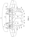
FIG. 2 is a perspective view of a rear section of the agricultural combine ofFIG. 1 , showing the windrow chute assembly in more detail in a first closed configuration; -
FIG. 3 is a perspective view of the rear section of the agricultural combine ofFIG. 1 , showing the windrow chute assembly in a second closed configuration; -
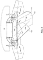
FIG. 4 is a perspective view of the rear section of the agricultural combine ofFIG. 1 , showing the windrow chute assembly in a third closed configuration; -
FIG. 5 is a perspective view of the rear section of the agricultural combine ofFIG. 1 , showing the windrow chute assembly in an open configuration. -
FIG. 6 is a side view of the rear section of the agricultural combine and windrow chute assembly ofFIG. 1 shown in the first closed configuration inFigure 2 ; -
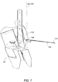
FIG. 7 is a side view of the rear section of the agricultural combine and windrow chute assembly ofFIG. 1 shown in the open configuration inFigure 5 ; -
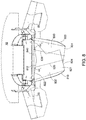
FIG. 8 is a perspective view of a rear section of the agricultural combine ofFIG. 1 , showing a windrow chute assembly in accordance with another embodiment, the windrow chute assembly shown in a closed configuration; -
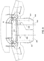
FIG. 9 is a perspective view of the rear section of the agricultural combine and windrow chute assembly ofFIG. 8 , showing the windrow chute assembly in a partially closed configuration; -
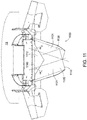
FIG. 10 is a perspective view of the rear section of the agricultural combine and windrow chute assembly ofFIG. 8 , showing the windrow chute assembly in an open configuration; -
FIG. 11 is a perspective view of a rear section of the agricultural combine ofFIG. 1 , showing a windrow chute assembly in accordance with another embodiment, the windrow chute assembly shown in a closed configuration; and -
FIG. 12 is a perspective view of the rear section of the agricultural combine and windrow chute assembly ofFIG. 11 , showing the windrow chute assembly in an open configuration. - Reference now will be made in detail to specific non-limiting examples illustrated in the drawings. Each example is provided by way of explanation, but not limitation. In fact, it will be apparent to those skilled in the art that various modifications and variations can be made to the described embodiments without departing from the scope of the invention. For instance, features illustrated or described as part of one embodiment can be used with another embodiment to yield a still further embodiment. Thus, it is intended that the present invention covers such modifications and variations.
- Windrow chutes in accordance with this description can be used with various types of the agricultural machinery, including but not limited to combines. Referring now to the drawings,
FIG. 1 illustrates a simplified, side view of one embodiment of anagricultural combine 10. In general, thecombine 10 may be configured the same as or similar to any suitable agricultural combine known in the art, such as a conventional style combine or axial combine. For instance, as shown inFIG. 1 , thecombine 10 can include an axially arranged threshingsystem 12 and a cleaning system. As is generally understood, the threshingsystem 12 may include one or morecylindrical rotors 14 rotatably supported within a cage or concave 16 for conveying a flow of crop material in a helical flow path along acircumferential space 18 defined between therotor 14 and the concave. As the crop material is moved through thespace 18 towards arear end 34 of the combine 10 (indicated by arrow 20), the crop (e.g., grain, legumes, and/or the like) may be separated from the crop residue (e.g., husks, pods and/or the like) and drop into the cleaning system. The crop residue may continue along the helical path and may be subsequently discharged through a discharge opening (not shown) defined at adownstream end 22 of the threshingsystem 12. -
Combine 10 also includes a cropresidue discharge system 24 for expelling crop residue from the combine to the field.Discharge system 24 includes aspreader 42 for evenly distributing the residue across the harvest width. In addition,discharge system 24 includes anopening 46 near the rear of the combine for windrowing. A windrow chute assembly100 is mounted to aframe 47 on the rear ofcombine 10 just beneathopening 46. - Referring now to
FIGS. 2-4 ,windrow chute assembly 100 is shown in more detail.Windrow chute assembly 100 is mounted to frame 47 and projects rearwardly fromcombine 10. Apivotable door 49 extendsadjacent frame 47 and is operable in one of two positions to control how crop residue is discharged to the field.Door 49 can be pivoted to a closed position which allows crop residue to enterspreader 42, in which case the material is spread across the width of the cut. Alternatively,door 49 can be pivoted to an open position to bypassspreader 42 and direct crop residue to windrowchute assembly 100 for depositing the material onto the field in windrows. -
Windrow chute assembly 100 includes achute body 110.Chute body 110 includes afloor plate 112 having a generally triangular configuration as shown.Chute body 110 also includes a plurality of chute sections that are independently movable. Windrow chute assemblies can include any number of movable chute sections. In the present example,chute body 110 includes afirst chute section 120 and asecond chute section 130. It will be appreciated that the drawing figures are not necessarily to scale, and thatfirst chute section 120 andsecond chute section 130 are not necessarily illustrated in correct proportion to the other parts ofcombine 10. As such, the illustrated dimensions offirst chute section 120 andsecond chute section 130, including but not limited to their respective length, width and depth, are not to scale, and the actual dimensions could be much greater or much less than the dimensions as shown. By way of example, it is contemplated that the length offirst chute section 120 and the length ofsecond chute section 130 could be several times larger than that shown. -
First chute section 120 has a firstproximal end 122 for receiving material fromcombine 10, and a firstdistal end 124 opposite the first proximal end for discharging material from the combine.First chute section 120 also defines afirst chute axis 126 that extends between firstproximal end 122 and firstdistal end 124 as shown.Second chute section 130 has a secondproximal end 132 for receiving material fromcombine 10, a seconddistal end 134 opposite the second proximal end for discharging material from the combine.Second chute section 130 also defines asecond chute axis 136 extending between secondproximal end 132 and seconddistal end 134 as shown. -
Floor plate 112 has afirst side 114 and asecond side 116 opposite the first side. Firstproximal end 122 offirst chute section 120 is movably mounted tofirst side 114, and secondproximal end 132 ofsecond chute section 130 is movably mounted tosecond side 116. Chute sections can be mounted to frames or floor plates in a variety of ways that allow the chute sections to move either independently or in unison. In the present example, firstproximal end 122 offirst chute section 120 is pivotably mounted tofirst side 114 with a first pivot joint 128. Similarly, secondproximal end 132 ofsecond chute section 130 is pivotably mounted tosecond side 116 with a second pivot joint 138. In this arrangement,first chute section 120 is pivotally mounted on a first pivot axis 129 that passes through first pivot joint 128. Similarly,second chute section 130 is pivotally mounted on a second pivot axis 139 that passes through second pivot joint 138. Second pivot axis 139 is parallel to and offset from first pivot axis 138. Pivot joints can take various forms, including but not limited to pin connections. In the present example, first pivot joint 128 and second pivot joint 138 includepins 113 that pass through bores that extend through the first andsecond chute sections floor plate 112. - A
transverse axis 140 is defined between firstproximal end 122 offirst chute section 120 and secondproximal end 132 ofsecond chute section 130. More specifically,transverse axis 140 intersects and extends between first pivot joint 128 and second pivot joint 138 as shown.Transverse axis 140 is perpendicular to the direction of forward travel T ofcombine 10. First pivot axis 129 and second pivot axis 139 are vertical axes that intersecttransverse axis 140 and are perpendicular to the transverse axis. Acenter axis 150 extends perpendicularly totransverse axis 140.Center axis 150 extends through a point P ontransverse axis 140 that is equidistant from first pivot axis 129 and second pivot axis 139. -
First chute section 120 andsecond chute section 130 are pivotably displaceable, independently of one another, and can assume an infinite number of positions and configurations relative totransverse axis 140. For example,first chute section 120 andsecond chute section 130 can be pivotably adjusted to a closed configuration to deposit crop residue onto the field in a narrow windrow.First chute section 120 andsecond chute section 130 can also be pivotably adjusted to a partially closed configuration to deposit crop residue onto the field in a wider windrow than in the closed configuration. In this way, the cross sectional shape and width of each windrow can be controlled by selecting a closed configuration or a partially closed configuration that corresponds to the desired windrow shape and width. Furthermore,first chute section 120 andsecond chute section 130 can be pivotably adjusted to an open position, in which the first and second chute sections are moved outwardly and away fromcenter axis 150, and toward the sides of the combine, where they do not obstruct the rear area of the combine. This ability to move the chute sections to the sides allows personnel standing on the ground to reach areas on the rear of the combine. For example, personnel can manually pivot the chute sections to the open position to reach items such as access handles and ladders that are pulled down to access the engine compartment. Each of the closed, partially closed, and open configurations will be described in more detail in the sections that follow. -
First chute section 120 is pivotably displaceable relative tofloor plate 112 so as to define a first angle of displacement α1 betweenfirst chute axis 126 andtransverse axis 140. Likewise,second chute section 130 is pivotably displaceable relative tofloor plate 112 so as to define a second angle of displacement α2 betweensecond chute axis 136 andtransverse axis 140. When in a closed configuration or a partially closed configuration,first chute section 120 andsecond chute section 130 can be pivotably adjusted to various angles relative totransverse axis 140 to control the position of each windrow relative to the center line ofcombine 10. For example, first andsecond chute sections - Chute sections can be designed to abut one another in the closed configuration. Alternatively, chute sections can be designed to partially overlap one another in the closed configuration. In the present example,
first chute section 120 andsecond chute section 130 partially overlap when in the closed configuration. The extent of overlap varies depending on the relative orientations of first andsecond chute sections second chute sections - Referring to
FIGS. 2 and6 ,first chute section 120 andsecond chute section 130 are pivoted toward one another in a closed configuration in which the chute sections are in the zero position. In this configuration,first chute section 120 andsecond chute section 130 are oriented such thatchute body 110 discharges crop residue directly behindcombine 10 on a line coinciding with the center line of the combine.First chute section 120 is pivoted inwardly 90 degrees relative totransverse axis 140, such that α1 is equal to 90 degrees. Likewise,second chute section 130 is pivoted inwardly 90 degrees relative totransverse axis 140, such that α2 is equal to 90 degrees.First chute axis 126 andsecond chute axis 136 are parallel to one another and to centeraxis 150. The sum of α1 and α2 is equal to 180 degrees. - Referring to
FIG. 3 ,first chute section 120 andsecond chute section 130 are shown in another closed configuration, with the chute sections pivoted to a left-bias position. In this configuration,first chute section 120 andsecond chute section 130 are oriented such that thechute body 110 discharges crop residue on a line offset to the left of the center line ofcombine 10. For purposes of this description, the term "left" refers to the left side of the center line when facing the rear of the combine.First chute section 120 andsecond chute section 130 can be sufficiently long to deposit the windrow at any desired distance from the center line, including a distance beyond the left tire track ofcombine 10. With the windrow placed outside of the tire tracks, a grain cart and tractor of equal width following directly behindcombine 10 does not have to straddle the windrow while receiving grain from the combine. Therefore, there is no risk that the grain cart and/or tractor will run over and disrupt the windrow as they followcombine 10.First chute section 120 is pivoted inwardly approximately 65 degrees relative totransverse axis 140, such that α1 is equal to 65 degrees.Second chute section 130 is pivoted inwardly 125 degrees relative totransverse axis 140, such that α2 is equal to 125 degrees. In this configuration,first chute section 120 overlapssecond chute section 130. As such,first chute axis 126 andsecond chute axis 136 are not parallel to one another. The sum of α1 and α2 is equal to 190 degrees. - Referring to
FIG. 4 ,first chute section 120 andsecond chute section 130 are shown in another closed configuration, with the chute sections pivoted to a right-bias position. In this configuration,first chute section 120 andsecond chute section 130 are oriented such that thechute body 110 discharges crop residue on a line offset to the right of the center line ofcombine 10. For purposes of this description, the term "right" refers to the right side of the center line when facing the rear of the combine.First chute section 120 andsecond chute section 130 can be sufficiently long to deposit the windrow at any desired distance from the center line, including a distance beyond the right tire track ofcombine 10. With the windrow placed outside of the tire tracks, a grain cart and tractor of equal width following directly behindcombine 10 does not have to straddle the windrow, as noted above. Therefore, there is no risk that the grain cart and/or tractor will run over and disrupt the windrow as they followcombine 10.First chute section 120 is pivoted inwardly approximately 125 degrees relative totransverse axis 140, such that α1 is equal to 125 degrees.Second chute section 130 is pivoted inwardly 65 degrees relative totransverse axis 140, such that α2 is equal to 65 degrees. In this configuration,first chute section 120 overlapssecond chute section 130. As such,first chute axis 126 andsecond chute axis 136 are not parallel to one another. The sum of α1 and α2 is equal to 190 degrees. -
Windrow chute assembly 100 can be pivoted to a closed configuration and remain fixed in that configuration during a windrow operation, with α1 and α2 remaining fixed (static mode). In addition, or in the alternative,windrow chute assembly 100 can pivot in a closed configuration during a windrow operation, with α1 and α2 changing in response to operating conditions (dynamic mode). For example,windrow chute assembly 100 can operate in the static mode, with the first and second chute sections in the zero position, as the combine is in the middle of a long windrow. When the combine reaches the end of the windrow and begins to turn around for the next pass,windrow chute assembly 100 can switch to a dynamic mode, in which the first and second chute sections gradually pivot toward a left-bias or right-bias configuration. As the first and second chute sections pivot to the left-bias or right-bias configuration during the turn, the windrow is discharged to the ground more smoothly than would be the case if the chute sections remain in the zero position, because the windrow is discharged along a curve that more closely to conforms to the shape of the arc through which the chute sections travel during the turn - When operating in a dynamic mode, the direction of bias will be the same direction as the turning direction. In the case of a right turn, for example, the operator can steer the first and second windrow chute sections from the zero position to the right-bias position during the turn. In the right-bias position, the chute sections are more tangential to the arc of the turn than in the zero position, which allows the windrow to be dropped more smoothly along an arc at the end of the windrow. The reverse would be done during a left turn. By steering the
windrow chute assembly 100 in response to steering of the combine, the operator can compensate for the changing orientation of the combine to maintain a smooth trajectory for the material being discharged. This results in a neater windrow at the end of each pass. If the windrow chute is kept in the zero position during the turn, the windrow will be discharged in a radially outward direction with respect to the arc shaped direction of travel, rather than tangentially. Straw that is discharged radially outwardly from the arc can succumb to a shearing action as the straw contacts the ground. This causes the material to roll, stretch, become degraded, and land in an irregular path or shape that a front steer baler can have trouble following. - First and second
windrow chute sections windrow chute sections - The zero position, left-bias position and right-bias position shown in
FIGS. 2-4 represent three different closed configurations. It should be appreciated that the zero position, left-bias position and right-bias position shown inFIGS. 2-4 are not the only positions in which thefirst chute section 120 andsecond chute section 130 can be arranged in a closed configuration.First chute section 120 andsecond chute section 130 can be arranged in other closed configurations with values for α1 and α2 that are different than those shown.First chute section 120 andsecond chute section 130 can also be arranged in an infinite number of partially closed configurations in which the first and second chute sections overlap to a lesser extent, and therefore are slightly more spread apart as compared to the closed configurations. Referring back toFIG. 2 , for example,first chute section 120 could be pivoted two degrees away fromsecond chute section 130. Similarly,second chute section 130 could be pivoted two degrees away fromfirst chute section 120. This would result in a partially closed configuration, withfirst chute axis 126 andsecond chute axis 136 each offset fromtransverse axis 140 by 88 degrees instead of 90 degrees.First chute axis 126 andsecond chute axis 136 would each be offset fromcenter axis 150 by two degrees. As such, firstdistal end 124 and seconddistal end 134 would be spread apart wider than shown inFIG. 2 , creating a wider chute at the distal ends to create a wider windrow than would be provided by the configuration shown inFIG. 2 . This outward adjustment offirst chute section 120 andsecond chute section 130 can be applied to any of the closed configurations shown inFIGS. 2-4 to create a partially closed configuration that produces a wider windrow. - Referring now to
FIGS. 5 and7 ,windrow chute assembly 100 is shown with first andsecond chute sections first chute section 120 is pivoted away fromsecond chute section 130 to a maximum extent, such thatfirst chute axis 126 is pivoted beyondtransverse axis 140 by an angle of -10 degrees. Likewise,second chute section 130 is pivoted away fromfirst chute section 120 to a maximum extent, such thatsecond chute axis 136 is pivoted beyondtransverse axis 140 by an angle of -10 degrees. Due to the limited space inFIG. 5 , the point of intersection betweenfirst chute axis 126 andtransverse axis 140, and the point of intersection betweensecond chute axis 136 and the transverse axis occur at or close to the edge of the Figure. Therefore, first angle of displacement α1 and the second angle of displacement α2 are shown at different locations along the first and second chute axes. First angle of displacement α1 is -10 degrees, and second angle of displacement α2 is -10 degrees. - In summary,
first chute section 120 andsecond chute section 130 are each capable of pivoting relative totransverse axis 140 through a range of -10 degrees to 125 degrees. The maximum sum of the first angle of displacement α1 and second angle of displacement α2 is 190 degrees. The minimum sum of the first angle of displacement α1 and second angle of displacement α2 is -20 degrees. It will be appreciated that the chute assemblies can be designed with chute sections that have smaller or larger pivot ranges. For example, an alternative design could feature chute sections that do not pivot past the transverse axis. In such a design, the first angle of displacement α1 and second angle of displacement α2 would each be 0 degrees when the first and second chute sections are moved to the open configuration. The minimum sum of α1 and α2 would be 0 degrees. - In the same design, or another alternative design, the first chute section and second chute section could assume the zero position when each chute section pivots through an angle greater than 90 degrees relative to the transverse axis. In such a design, the first chute axis would intersect the second chute axis when the chute sections are in the zero position. As each chute section is pivoted closer and closer toward the zero position, the width of the chute body at the distal end would decrease, providing a decreased windrow width.
- Referring back to
FIG. 2 ,first chute section 120 includes a firstbottom wall section 121 and afirst sidewall section 123. Similarly,second chute section 130 includes a secondbottom wall section 131 and asecond sidewall section 133. Firstbottom wall section 121 and secondbottom wall section 131 are configured to convey crop residue out offirst chute section 120 andsecond chute section 130, respectively. Firstbottom wall section 121 partially extends over secondbottom wall section 131 in the closed configuration, such that the first and second bottom wall sections overlap.First sidewall section 131 andsecond sidewall section 133 also assist with conveying crop residue out offirst chute section 120 andsecond chute section 130, respectively, while also limiting outward dispersion of material. This keeps the crop residue concentrated so that the material exitschute body 110 in a narrow stream to create a narrow windrow. - First
bottom wall section 121 andfirst sidewall section 131 form an L-shaped profile, as seen best inFIG. 7 , which shows the L-shaped profile offirst chute 120. Similarly, secondbottom wall section 121 andsecond sidewall section 131 form an L-shaped profile that is the mirror or reverse image of the profile created by firstbottom wall section 121 andfirst sidewall section 131. In this arrangement,first chute section 120 andsecond chute section 130 form anopen channel 118 when the chute sections are brought together in the closed configuration. That is,first chute section 120 andsecond chute section 130 form a box shaped channel having a bottom wall and two sidewalls, the channel being open at the top with no top wall. - It will be appreciated that windrow chute assemblies can be designed with chute sections having other geometries suitable for conveying crop residue and depositing the material in windrows. For example, the first chute section could have a first round concave shape and the second chute section could have a second round concave shape that forms an open U-shaped channel in a closed configuration. Alternatively, first chute section and second chute section could each be in the form of three-sided rectangles, each having a top face, side face and bottom face, and being open on the sides facing one other, thereby forming a box-shaped conduit in the closed configuration that is closed on all sides. Regardless of the selected geometry, the cross sectional profile of first chute section can be the mirror image of the cross sectional profile of the second chute section, thereby forming a symmetrical shape in the open and closed configurations. Alternatively, the cross sectional profile of first chute section can be different from the cross sectional profile of the second chute section, thereby forming an asymmetrical shape in the open and closed configurations.
-
FIGS. 8-10 illustrate awindrow chute assembly 800 in accordance with another embodiment.Windrow chute assembly 800 has many of the same components aswindrow chute assembly 100. For brevity, some components that are identical to corresponding components inwindrow chute assembly 100 will not be described. -
Windrow chute assembly 800 includes achute body 810 with afloor plate 812 having a narrow triangular configuration as shown.Chute body 810 also includes afirst chute section 820 with afirst chute axis 826 and asecond chute section 830 with asecond chute axis 836.First chute section 820 has abottom wall 821 having a "P" shaped profile as shown, with a firstproximal end 822 that is much wider than a firstdistal end 824.Second chute section 830 has abottom wall 831 with a "backward P" shaped profile that is the mirror or reverse image of the "P" shaped profile offirst chute section 820. -
First chute section 820 andsecond chute section 830 assume the closed position when each chute section pivots through an angle greater than 90 degrees relative to thetransverse axis 840, as shown inFIG. 8 . In particular,first chute section 820 andsecond chute section 830 each pivot through an angle of 110 degrees relative totransverse axis 840. As such, first angle of displacement α1 is equal to 110 degrees, and second angle of displacement α2 is equal to 110 degrees.First chute axis 826 intersectssecond chute axis 836 in this configuration. InFIG. 9 ,windrow chute assembly 800 is shown in a partially closed configuration, where each chute section is pivoted through an angle equal to 90 degrees relative to the transverse axis. InFIG. 10 ,windrow chute assembly 800 is shown in an open configuration, where each chute section is pivoted through an angle equal to -10 degrees relative totransverse axis 840. -
FIGS. 11 and12 illustrate awindrow chute assembly 1100 in accordance with another embodiment.Windrow chute assembly 1100 has many of the same components aswindrow chute assemblies windrow chute assemblies -
Windrow chute assembly 1100 includes achute body 1110 with afloor plate 1112 having a triangular configuration as shown.Chute body 1110 also includes afirst chute section 1120 with a first chute axis 1126 and asecond chute section 1130 with a second chute axis 1136.First chute section 1120 has a bottom wall having a rectangular shaped profile as shown, with a first proximal end 1122 and a first distal end 1124. First proximal end 1122 has the same width as first distal end 1124.Second chute section 1130 also has abottom wall 1131 with a rectangular shaped profile that is the mirror or reverse image of the rectangular shaped profile offirst chute section 1120. -
First chute section 1120 andsecond chute section 1130 assume the closed position when each chute section pivots through an angle greater than 90 degrees relative to the transverse axis, as shown inFIG. 11 . In particular,first chute section 1120 andsecond chute section 1130 each pivot through an angle of 110 degrees relative to thetransverse axis 1140. As such, first angle of displacement α1 is equal to 110 degrees, and second angle of displacement α2 is equal to 110 degrees. InFIG. 12 ,windrow chute assembly 1100 is shown in an open configuration, where each chute section is pivoted through an angle equal to -10 degrees relative totransverse axis 1140.
Claims (20)
- A windrow chute assembly (100, 800, 1100) for an agricultural vehicle (10), the windrow chute assembly (100, 800, 1100) comprising:a chute body (110, 810, 1110) comprising a plurality of movable chute sections, the plurality of movable chute sections comprising a first chute section (120, 820, 1120) and a second chute section (130, 830, 1130),the first chute section (120, 820, 1120) having a first proximal end (122, 822,1122) for receiving material from the agricultural vehicle (10), a first distal end (124, 824, 1124) opposite the first proximal end (122, 822,1122) for discharging material from the agricultural vehicle (10), and a first chute axis (126, 826, 1126) extending between the first proximal end (122, 822,1122) and the first distal end (124, 824, 1124),the second chute section (130, 830, 1130) having a second proximal end (132) for receiving material from the agricultural vehicle (10), a second distal end (134) opposite the second proximal end (132) for discharging material from the agricultural vehicle (10), and a second chute axis (136, 836, 1136) extending between the second proximal end (132) and the second distal end (134),
characterized in that,the first proximal end (122, 822,1122) of the first chute section (120, 820, 1120) and the second proximal end (132) of the second chute section (130, 830, 1130) defining a transverse axis (140, 840, 1140) therebetween, the first chute section (120, 820, 1120) being displaceable so as to define a first angle of displacement (α1) between the first chute axis (126, 826, 1126) and the transverse axis (140, 840, 1140), and the second chute section (130, 830, 1130) being displaceable so as to define a second angle of displacement (α2) between the second chute axis (136, 836, 1136) and the transverse axis (140, 840, 1140),the first chute section (120, 820, 1120) and the second chute section (130, 830, 1130) being displaceable toward one another to a closed configuration, in which a sum of the first angle of displacement (α1) and the second angle of displacement (α2) is a maximum, and displaceable away from one another to an open configuration, in which the sum of the first angle of displacement (α1) and the second angle of displacement (α2) is a minimum. - The windrow chute assembly (100, 800, 1100) according to claim 1, characterized in that the first chute section (120, 820, 1120) is pivotally mountable on a first pivot axis (129), and the second chute section (130, 830, 1130) is pivotally mountable on a second pivot axis (139) offset from the first pivot axis (129).
- The windrow chute assembly (100, 800, 1100) according to claim 2, characterized in that the first pivot axis (129) is parallel to the second pivot axis (139).
- The windrow chute assembly (100, 800, 1100) according to claim 2 or 3, characterized in that the first pivot axis (129) and the second pivot axis (139) are perpendicular to the transverse axis (140, 840, 1140).
- The windrow chute assembly (100, 800, 1100) according to any one of claims 2-4, characterized in that the first pivot axis (129) and the second pivot axis (139) are vertical axes.
- The windrow chute assembly (100, 800, 1100) according to any one of the preceding claims, characterized in that the first chute section (120, 820, 1120) is displaceable through an angle greater than ninety degrees relative to the transverse axis (140, 840, 1140), and the second chute section (130, 830, 1130) is displaceable through an angle greater than ninety degrees relative to the transverse axis (140, 840, 1140).
- The windrow chute assembly (100, 800, 1100) according to any one of the preceding claims, characterized in that the sum of the first angle of displacement (α1) and the second angle of displacement (α2) is 180 degrees when the first chute section (120, 820, 1120) and the second chute section (130, 830, 1130) are in the closed configuration.
- The windrow chute assembly (100, 800, 1100) according to any one of the preceding claims, characterized in that the sum of the first angle of displacement (α1) and the second angle of displacement (α2) is less than 0 degrees when the first chute section (120, 820, 1120) and the second chute section (130, 830, 1130) are in the open configuration.
- The windrow chute assembly (100, 800, 1100) according to any one of the preceding claims, further defining a center axis (150) that extends perpendicularly to the transverse axis (140, 840, 1140) at a point (P) equidistant from the first proximal end (122, 822,1122) of the first chute section (120, 820, 1120) and the second proximal end (132) of the second chute section (130, 830, 1130).
- The windrow chute assembly (100, 800, 1100) according to claim 9, characterized in that the first chute section (120, 820, 1120) and the second chute section (130, 830, 1130) are each pivotable toward the center axis (150) to assume a zero position.
- The windrow chute assembly (100, 800, 1100) according to claim 10, characterized in that the first chute axis (126, 826, 1126) is parallel to the second chute axis (136, 836, 1136) in the zero position.
- The windrow chute assembly (100, 800, 1100) according to any of claims 1-10, characterized in that the first chute axis (126, 826, 1126) intersects the second chute axis (136, 836, 1136) in the closed configuration.
- The windrow chute assembly (100, 800, 1100) according to claim 9, characterized in that the first chute section (120, 820, 1120) and the second chute section (130, 830, 1130) are movable to the closed configuration at a zero position in which the first chute axis (126, 826, 1126) and the second chute axis (136, 836, 1136) are parallel to the center axis (150).
- The windrow chute assembly (100, 800, 1100) according to claim 9, characterized in that the first chute section (120, 820, 1120) and the second chute section (130, 830, 1130) are movable to the closed configuration at a left bias position in which the first angle of displacement (α1) is less than ninety degrees and the second angle of displacement (α2) greater than ninety degrees.
- The windrow chute assembly (100, 800, 1100) according to claim 9, characterized in that the first chute section (120, 820, 1120) and the second chute section (130, 830, 1130) are movable to the closed configuration at a right bias position in which the first angle of displacement (α1) is greater than ninety degrees and the second angle of displacement (α2) is less than ninety degrees.
- The windrow chute assembly (100, 800, 1100) according to any one of the preceding claims, characterized in that the first chute section (120, 820, 1120) comprises a first bottom wall section (121) and the second chute section (130, 830, 1130) has a second bottom wall section (131), the first bottom wall section (121) and the second bottom wall section (131) configured to convey material out of the first chute section (120, 820, 1120) and the second chute section (130, 830, 1130), respectively.
- The windrow chute assembly (100, 800, 1100) according to any one of the preceding claims, characterized in that the first chute section (120, 820, 1120) comprises a first sidewall (131) and the second chute section (130, 830, 1130) comprises a second sidewall (133).
- The windrow chute assembly (100, 800, 1100) according to claim 16, characterized in that the first bottom wall section (121) overlaps the second bottom wall section (131) in the closed configuration.
- The windrow chute assembly (100, 800, 1100) according to any one of the preceding claims, characterized in that the first chute section (120, 820, 1120) and the second chute section (130, 830, 1130) form an open channel (118) in the closed configuration.
- The windrow chute assembly (100, 800, 1100) according to any one of claims 1-18, characterized in that the first chute section (120, 820, 1120) and the second chute section (130, 830, 1130) form a closed conduit in the closed configuration.
Applications Claiming Priority (1)
| Application Number | Priority Date | Filing Date | Title |
|---|---|---|---|
| US15/709,705 US10336546B2 (en) | 2017-09-20 | 2017-09-20 | Windrow chute with independently movable chute sections |
Publications (2)
| Publication Number | Publication Date |
|---|---|
| EP3459335A1 true EP3459335A1 (en) | 2019-03-27 |
| EP3459335B1 EP3459335B1 (en) | 2020-06-24 |
Family
ID=63637800
Family Applications (1)
| Application Number | Title | Priority Date | Filing Date |
|---|---|---|---|
| EP18194920.7A Active EP3459335B1 (en) | 2017-09-20 | 2018-09-17 | Windrow chute with independently movable chute sections |
Country Status (2)
| Country | Link |
|---|---|
| US (1) | US10336546B2 (en) |
| EP (1) | EP3459335B1 (en) |
Cited By (1)
| Publication number | Priority date | Publication date | Assignee | Title |
|---|---|---|---|---|
| US20200187418A1 (en) * | 2018-12-12 | 2020-06-18 | Cnh Industrial America Llc | Extendable table adjusting windrow chute |
Families Citing this family (6)
| Publication number | Priority date | Publication date | Assignee | Title |
|---|---|---|---|---|
| EP3162182B1 (en) * | 2015-10-29 | 2018-02-28 | Kverneland Group Kerteminde AS | Swathing unit |
| BR102019009913A2 (en) * | 2018-05-17 | 2020-05-05 | Cnh Ind America Llc | discharge of waste from a combine harvester |
| US12004447B2 (en) * | 2021-10-01 | 2024-06-11 | Cnh Industrial America Llc | Pivotable windrow chute for combine harvester |
| EP4173466B1 (en) * | 2021-11-02 | 2024-08-21 | CNH Industrial Belgium N.V. | Adjustable spreader system for an agricultural harvester |
| US20240138284A1 (en) * | 2022-10-31 | 2024-05-02 | Deere & Company | Map based farming for windrower operation |
| US12619266B2 (en) * | 2023-07-19 | 2026-05-05 | Deere & Company | Windrower implement with merger attachment |
Citations (5)
| Publication number | Priority date | Publication date | Assignee | Title |
|---|---|---|---|---|
| US3683602A (en) * | 1970-12-16 | 1972-08-15 | Int Harvester Co | Crop aerating mechanism for harvesters |
| WO2004112457A1 (en) * | 2003-06-24 | 2004-12-29 | Rekordverken Sweden Ab | Combine harvester having spreader for crop residues |
| US20140096498A1 (en) * | 2012-10-04 | 2014-04-10 | Cnh America Llc | Adjustable windrow assembly for an agricultural vehicle |
| US20160316623A1 (en) * | 2015-04-30 | 2016-11-03 | Cnh Industrial America Llc | Crop Residue Management Deflector |
| US20170112055A1 (en) * | 2015-10-27 | 2017-04-27 | Cnh Industrial America Llc | Agricultural harvester residue spreader automation |
Family Cites Families (5)
| Publication number | Priority date | Publication date | Assignee | Title |
|---|---|---|---|---|
| US6591972B1 (en) * | 2002-01-02 | 2003-07-15 | Glen Forrest | Grain leveling apparatus for uniformly filling a grain wagon |
| US6939221B1 (en) | 2004-04-26 | 2005-09-06 | Redekop Chaff Systems Ltd. | Combine harvester with a spreader having independent spread width control |
| US7559833B2 (en) | 2007-06-29 | 2009-07-14 | Cnh America Llc | Adjustable convergence panels for discharging residue from a combine harvester |
| DE202014102621U1 (en) | 2014-06-05 | 2015-06-11 | Heuling Maschinenbau Gmbh & Co. Kg | Distribution device for shredders on a combine harvester |
| US9521808B2 (en) | 2014-11-19 | 2016-12-20 | Cnh Industrial America Llc | Harvester chaff pan assembly with moveable deflector components |
-
2017
- 2017-09-20 US US15/709,705 patent/US10336546B2/en active Active
-
2018
- 2018-09-17 EP EP18194920.7A patent/EP3459335B1/en active Active
Patent Citations (5)
| Publication number | Priority date | Publication date | Assignee | Title |
|---|---|---|---|---|
| US3683602A (en) * | 1970-12-16 | 1972-08-15 | Int Harvester Co | Crop aerating mechanism for harvesters |
| WO2004112457A1 (en) * | 2003-06-24 | 2004-12-29 | Rekordverken Sweden Ab | Combine harvester having spreader for crop residues |
| US20140096498A1 (en) * | 2012-10-04 | 2014-04-10 | Cnh America Llc | Adjustable windrow assembly for an agricultural vehicle |
| US20160316623A1 (en) * | 2015-04-30 | 2016-11-03 | Cnh Industrial America Llc | Crop Residue Management Deflector |
| US20170112055A1 (en) * | 2015-10-27 | 2017-04-27 | Cnh Industrial America Llc | Agricultural harvester residue spreader automation |
Cited By (2)
| Publication number | Priority date | Publication date | Assignee | Title |
|---|---|---|---|---|
| US20200187418A1 (en) * | 2018-12-12 | 2020-06-18 | Cnh Industrial America Llc | Extendable table adjusting windrow chute |
| US10827674B2 (en) * | 2018-12-12 | 2020-11-10 | Cnh Industrial America Llc | Extendable table adjusting windrow chute |
Also Published As
| Publication number | Publication date |
|---|---|
| US20190084764A1 (en) | 2019-03-21 |
| US10336546B2 (en) | 2019-07-02 |
| EP3459335B1 (en) | 2020-06-24 |
| BR102018069098A2 (en) | 2019-05-28 |
Similar Documents
| Publication | Publication Date | Title |
|---|---|---|
| EP3459335B1 (en) | Windrow chute with independently movable chute sections | |
| EP3469878B1 (en) | Roll center for harvester attachment frame control arms | |
| EP3424293B1 (en) | Residue management system with a selection door for an agricultural vehicle | |
| EP3409095B1 (en) | Agricultural combine with reversing chopper rotor | |
| EP3064052B1 (en) | Agricultural reel cam system | |
| EP3153001B1 (en) | Material guide for a straw hood of an agricultural vehicle | |
| US10993373B2 (en) | Corn header row unit | |
| EP3573445B1 (en) | Corn header adjustable divider point | |
| EP3571918B1 (en) | Discharging residue from a combine harvester | |
| US20240215484A1 (en) | Residue Chopper and Spreader Arrangement | |
| EP3666056B1 (en) | Extendable table adjusting windrow chute | |
| CA3016940A1 (en) | Folding agricultural head | |
| EP3338528B1 (en) | Straw spreader and chaff spreader for a combine harvester | |
| US20240215494A1 (en) | Residue Chopper and Spreader Arrangement | |
| EP4677988A1 (en) | Spreader system for an agricultural harvester | |
| WO2024235394A1 (en) | Pick-up attachment for a harvesting machine | |
| EP4697932A1 (en) | Pick-up attachment for a harvesting machine | |
| BR102018069098B1 (en) | ROW DRAIN ASSEMBLY FOR AN AGRICULTURAL VEHICLE |
Legal Events
| Date | Code | Title | Description |
|---|---|---|---|
| PUAI | Public reference made under article 153(3) epc to a published international application that has entered the european phase |
Free format text: ORIGINAL CODE: 0009012 |
|
| STAA | Information on the status of an ep patent application or granted ep patent |
Free format text: STATUS: THE APPLICATION HAS BEEN PUBLISHED |
|
| AK | Designated contracting states |
Kind code of ref document: A1 Designated state(s): AL AT BE BG CH CY CZ DE DK EE ES FI FR GB GR HR HU IE IS IT LI LT LU LV MC MK MT NL NO PL PT RO RS SE SI SK SM TR |
|
| AX | Request for extension of the european patent |
Extension state: BA ME |
|
| STAA | Information on the status of an ep patent application or granted ep patent |
Free format text: STATUS: REQUEST FOR EXAMINATION WAS MADE |
|
| 17P | Request for examination filed |
Effective date: 20190927 |
|
| RBV | Designated contracting states (corrected) |
Designated state(s): AL AT BE BG CH CY CZ DE DK EE ES FI FR GB GR HR HU IE IS IT LI LT LU LV MC MK MT NL NO PL PT RO RS SE SI SK SM TR |
|
| GRAP | Despatch of communication of intention to grant a patent |
Free format text: ORIGINAL CODE: EPIDOSNIGR1 |
|
| STAA | Information on the status of an ep patent application or granted ep patent |
Free format text: STATUS: GRANT OF PATENT IS INTENDED |
|
| RIC1 | Information provided on ipc code assigned before grant |
Ipc: A01D 57/28 20060101ALI20191211BHEP Ipc: A01D 41/12 20060101AFI20191211BHEP |
|
| INTG | Intention to grant announced |
Effective date: 20200115 |
|
| GRAS | Grant fee paid |
Free format text: ORIGINAL CODE: EPIDOSNIGR3 |
|
| GRAA | (expected) grant |
Free format text: ORIGINAL CODE: 0009210 |
|
| STAA | Information on the status of an ep patent application or granted ep patent |
Free format text: STATUS: THE PATENT HAS BEEN GRANTED |
|
| AK | Designated contracting states |
Kind code of ref document: B1 Designated state(s): AL AT BE BG CH CY CZ DE DK EE ES FI FR GB GR HR HU IE IS IT LI LT LU LV MC MK MT NL NO PL PT RO RS SE SI SK SM TR |
|
| REG | Reference to a national code |
Ref country code: GB Ref legal event code: FG4D Ref country code: DE Ref legal event code: R082 Ref document number: 602018005527 Country of ref document: DE Representative=s name: KROHER . STROBEL RECHTS- UND PATENTANWAELTE PA, DE Ref country code: DE Ref legal event code: R082 Ref document number: 602018005527 Country of ref document: DE Representative=s name: KROHER STROBEL RECHTS- UND PATENTANWAELTE PART, DE |
|
| REG | Reference to a national code |
Ref country code: CH Ref legal event code: EP |
|
| REG | Reference to a national code |
Ref country code: AT Ref legal event code: REF Ref document number: 1282953 Country of ref document: AT Kind code of ref document: T Effective date: 20200715 |
|
| REG | Reference to a national code |
Ref country code: DE Ref legal event code: R096 Ref document number: 602018005527 Country of ref document: DE |
|
| REG | Reference to a national code |
Ref country code: IE Ref legal event code: FG4D |
|
| PG25 | Lapsed in a contracting state [announced via postgrant information from national office to epo] |
Ref country code: LT Free format text: LAPSE BECAUSE OF FAILURE TO SUBMIT A TRANSLATION OF THE DESCRIPTION OR TO PAY THE FEE WITHIN THE PRESCRIBED TIME-LIMIT Effective date: 20200624 Ref country code: FI Free format text: LAPSE BECAUSE OF FAILURE TO SUBMIT A TRANSLATION OF THE DESCRIPTION OR TO PAY THE FEE WITHIN THE PRESCRIBED TIME-LIMIT Effective date: 20200624 Ref country code: GR Free format text: LAPSE BECAUSE OF FAILURE TO SUBMIT A TRANSLATION OF THE DESCRIPTION OR TO PAY THE FEE WITHIN THE PRESCRIBED TIME-LIMIT Effective date: 20200925 Ref country code: SE Free format text: LAPSE BECAUSE OF FAILURE TO SUBMIT A TRANSLATION OF THE DESCRIPTION OR TO PAY THE FEE WITHIN THE PRESCRIBED TIME-LIMIT Effective date: 20200624 Ref country code: NO Free format text: LAPSE BECAUSE OF FAILURE TO SUBMIT A TRANSLATION OF THE DESCRIPTION OR TO PAY THE FEE WITHIN THE PRESCRIBED TIME-LIMIT Effective date: 20200924 |
|
| REG | Reference to a national code |
Ref country code: LT Ref legal event code: MG4D |
|
| PG25 | Lapsed in a contracting state [announced via postgrant information from national office to epo] |
Ref country code: BG Free format text: LAPSE BECAUSE OF FAILURE TO SUBMIT A TRANSLATION OF THE DESCRIPTION OR TO PAY THE FEE WITHIN THE PRESCRIBED TIME-LIMIT Effective date: 20200924 Ref country code: RS Free format text: LAPSE BECAUSE OF FAILURE TO SUBMIT A TRANSLATION OF THE DESCRIPTION OR TO PAY THE FEE WITHIN THE PRESCRIBED TIME-LIMIT Effective date: 20200624 Ref country code: HR Free format text: LAPSE BECAUSE OF FAILURE TO SUBMIT A TRANSLATION OF THE DESCRIPTION OR TO PAY THE FEE WITHIN THE PRESCRIBED TIME-LIMIT Effective date: 20200624 Ref country code: LV Free format text: LAPSE BECAUSE OF FAILURE TO SUBMIT A TRANSLATION OF THE DESCRIPTION OR TO PAY THE FEE WITHIN THE PRESCRIBED TIME-LIMIT Effective date: 20200624 |
|
| REG | Reference to a national code |
Ref country code: NL Ref legal event code: MP Effective date: 20200624 |
|
| REG | Reference to a national code |
Ref country code: AT Ref legal event code: MK05 Ref document number: 1282953 Country of ref document: AT Kind code of ref document: T Effective date: 20200624 |
|
| PG25 | Lapsed in a contracting state [announced via postgrant information from national office to epo] |
Ref country code: NL Free format text: LAPSE BECAUSE OF FAILURE TO SUBMIT A TRANSLATION OF THE DESCRIPTION OR TO PAY THE FEE WITHIN THE PRESCRIBED TIME-LIMIT Effective date: 20200624 Ref country code: AL Free format text: LAPSE BECAUSE OF FAILURE TO SUBMIT A TRANSLATION OF THE DESCRIPTION OR TO PAY THE FEE WITHIN THE PRESCRIBED TIME-LIMIT Effective date: 20200624 |
|
| PG25 | Lapsed in a contracting state [announced via postgrant information from national office to epo] |
Ref country code: SM Free format text: LAPSE BECAUSE OF FAILURE TO SUBMIT A TRANSLATION OF THE DESCRIPTION OR TO PAY THE FEE WITHIN THE PRESCRIBED TIME-LIMIT Effective date: 20200624 Ref country code: EE Free format text: LAPSE BECAUSE OF FAILURE TO SUBMIT A TRANSLATION OF THE DESCRIPTION OR TO PAY THE FEE WITHIN THE PRESCRIBED TIME-LIMIT Effective date: 20200624 Ref country code: RO Free format text: LAPSE BECAUSE OF FAILURE TO SUBMIT A TRANSLATION OF THE DESCRIPTION OR TO PAY THE FEE WITHIN THE PRESCRIBED TIME-LIMIT Effective date: 20200624 Ref country code: CZ Free format text: LAPSE BECAUSE OF FAILURE TO SUBMIT A TRANSLATION OF THE DESCRIPTION OR TO PAY THE FEE WITHIN THE PRESCRIBED TIME-LIMIT Effective date: 20200624 Ref country code: ES Free format text: LAPSE BECAUSE OF FAILURE TO SUBMIT A TRANSLATION OF THE DESCRIPTION OR TO PAY THE FEE WITHIN THE PRESCRIBED TIME-LIMIT Effective date: 20200624 Ref country code: AT Free format text: LAPSE BECAUSE OF FAILURE TO SUBMIT A TRANSLATION OF THE DESCRIPTION OR TO PAY THE FEE WITHIN THE PRESCRIBED TIME-LIMIT Effective date: 20200624 Ref country code: PT Free format text: LAPSE BECAUSE OF FAILURE TO SUBMIT A TRANSLATION OF THE DESCRIPTION OR TO PAY THE FEE WITHIN THE PRESCRIBED TIME-LIMIT Effective date: 20201026 |
|
| PG25 | Lapsed in a contracting state [announced via postgrant information from national office to epo] |
Ref country code: SK Free format text: LAPSE BECAUSE OF FAILURE TO SUBMIT A TRANSLATION OF THE DESCRIPTION OR TO PAY THE FEE WITHIN THE PRESCRIBED TIME-LIMIT Effective date: 20200624 Ref country code: PL Free format text: LAPSE BECAUSE OF FAILURE TO SUBMIT A TRANSLATION OF THE DESCRIPTION OR TO PAY THE FEE WITHIN THE PRESCRIBED TIME-LIMIT Effective date: 20200624 Ref country code: IS Free format text: LAPSE BECAUSE OF FAILURE TO SUBMIT A TRANSLATION OF THE DESCRIPTION OR TO PAY THE FEE WITHIN THE PRESCRIBED TIME-LIMIT Effective date: 20201024 |
|
| REG | Reference to a national code |
Ref country code: DE Ref legal event code: R097 Ref document number: 602018005527 Country of ref document: DE |
|
| PG25 | Lapsed in a contracting state [announced via postgrant information from national office to epo] |
Ref country code: DK Free format text: LAPSE BECAUSE OF FAILURE TO SUBMIT A TRANSLATION OF THE DESCRIPTION OR TO PAY THE FEE WITHIN THE PRESCRIBED TIME-LIMIT Effective date: 20200624 |
|
| PLBE | No opposition filed within time limit |
Free format text: ORIGINAL CODE: 0009261 |
|
| STAA | Information on the status of an ep patent application or granted ep patent |
Free format text: STATUS: NO OPPOSITION FILED WITHIN TIME LIMIT |
|
| 26N | No opposition filed |
Effective date: 20210325 |
|
| REG | Reference to a national code |
Ref country code: DE Ref legal event code: R082 Ref document number: 602018005527 Country of ref document: DE Representative=s name: KROHER STROBEL RECHTS- UND PATENTANWAELTE PART, DE |
|
| REG | Reference to a national code |
Ref country code: BE Ref legal event code: MM Effective date: 20200930 |
|
| PG25 | Lapsed in a contracting state [announced via postgrant information from national office to epo] |
Ref country code: LU Free format text: LAPSE BECAUSE OF NON-PAYMENT OF DUE FEES Effective date: 20200917 |
|
| PG25 | Lapsed in a contracting state [announced via postgrant information from national office to epo] |
Ref country code: SI Free format text: LAPSE BECAUSE OF FAILURE TO SUBMIT A TRANSLATION OF THE DESCRIPTION OR TO PAY THE FEE WITHIN THE PRESCRIBED TIME-LIMIT Effective date: 20200624 Ref country code: IE Free format text: LAPSE BECAUSE OF NON-PAYMENT OF DUE FEES Effective date: 20200917 Ref country code: BE Free format text: LAPSE BECAUSE OF NON-PAYMENT OF DUE FEES Effective date: 20200930 |
|
| REG | Reference to a national code |
Ref country code: CH Ref legal event code: PL |
|
| PG25 | Lapsed in a contracting state [announced via postgrant information from national office to epo] |
Ref country code: TR Free format text: LAPSE BECAUSE OF FAILURE TO SUBMIT A TRANSLATION OF THE DESCRIPTION OR TO PAY THE FEE WITHIN THE PRESCRIBED TIME-LIMIT Effective date: 20200624 Ref country code: MT Free format text: LAPSE BECAUSE OF FAILURE TO SUBMIT A TRANSLATION OF THE DESCRIPTION OR TO PAY THE FEE WITHIN THE PRESCRIBED TIME-LIMIT Effective date: 20200624 Ref country code: CY Free format text: LAPSE BECAUSE OF FAILURE TO SUBMIT A TRANSLATION OF THE DESCRIPTION OR TO PAY THE FEE WITHIN THE PRESCRIBED TIME-LIMIT Effective date: 20200624 |
|
| PG25 | Lapsed in a contracting state [announced via postgrant information from national office to epo] |
Ref country code: MK Free format text: LAPSE BECAUSE OF FAILURE TO SUBMIT A TRANSLATION OF THE DESCRIPTION OR TO PAY THE FEE WITHIN THE PRESCRIBED TIME-LIMIT Effective date: 20200624 Ref country code: MC Free format text: LAPSE BECAUSE OF FAILURE TO SUBMIT A TRANSLATION OF THE DESCRIPTION OR TO PAY THE FEE WITHIN THE PRESCRIBED TIME-LIMIT Effective date: 20200624 |
|
| PG25 | Lapsed in a contracting state [announced via postgrant information from national office to epo] |
Ref country code: LI Free format text: LAPSE BECAUSE OF NON-PAYMENT OF DUE FEES Effective date: 20210930 Ref country code: CH Free format text: LAPSE BECAUSE OF NON-PAYMENT OF DUE FEES Effective date: 20210930 |
|
| PGFP | Annual fee paid to national office [announced via postgrant information from national office to epo] |
Ref country code: DE Payment date: 20250926 Year of fee payment: 8 |
|
| PGFP | Annual fee paid to national office [announced via postgrant information from national office to epo] |
Ref country code: IT Payment date: 20250922 Year of fee payment: 8 |
|
| PGFP | Annual fee paid to national office [announced via postgrant information from national office to epo] |
Ref country code: GB Payment date: 20250923 Year of fee payment: 8 |
|
| PGFP | Annual fee paid to national office [announced via postgrant information from national office to epo] |
Ref country code: FR Payment date: 20250925 Year of fee payment: 8 |