EP3458342B1 - Track system - Google Patents
Track system Download PDFInfo
- Publication number
- EP3458342B1 EP3458342B1 EP17815841.6A EP17815841A EP3458342B1 EP 3458342 B1 EP3458342 B1 EP 3458342B1 EP 17815841 A EP17815841 A EP 17815841A EP 3458342 B1 EP3458342 B1 EP 3458342B1
- Authority
- EP
- European Patent Office
- Prior art keywords
- trailing
- leading
- frame member
- axis
- pivot
- Prior art date
- Legal status (The legal status is an assumption and is not a legal conclusion. Google has not performed a legal analysis and makes no representation as to the accuracy of the status listed.)
- Active
Links
Images













Classifications
-
- B—PERFORMING OPERATIONS; TRANSPORTING
- B62—LAND VEHICLES FOR TRAVELLING OTHERWISE THAN ON RAILS
- B62D—MOTOR VEHICLES; TRAILERS
- B62D55/00—Endless track vehicles
- B62D55/08—Endless track units; Parts thereof
- B62D55/084—Endless-track units or carriages mounted separably, adjustably or extensibly on vehicles, e.g. portable track units
-
- B—PERFORMING OPERATIONS; TRANSPORTING
- B62—LAND VEHICLES FOR TRAVELLING OTHERWISE THAN ON RAILS
- B62D—MOTOR VEHICLES; TRAILERS
- B62D55/00—Endless track vehicles
- B62D55/04—Endless track vehicles with tracks and alternative ground wheels, e.g. changeable from endless track vehicle into wheeled vehicle and vice versa
-
- B—PERFORMING OPERATIONS; TRANSPORTING
- B62—LAND VEHICLES FOR TRAVELLING OTHERWISE THAN ON RAILS
- B62D—MOTOR VEHICLES; TRAILERS
- B62D55/00—Endless track vehicles
- B62D55/08—Endless track units; Parts thereof
-
- B—PERFORMING OPERATIONS; TRANSPORTING
- B62—LAND VEHICLES FOR TRAVELLING OTHERWISE THAN ON RAILS
- B62D—MOTOR VEHICLES; TRAILERS
- B62D55/00—Endless track vehicles
- B62D55/08—Endless track units; Parts thereof
- B62D55/10—Bogies; Frames
-
- B—PERFORMING OPERATIONS; TRANSPORTING
- B62—LAND VEHICLES FOR TRAVELLING OTHERWISE THAN ON RAILS
- B62D—MOTOR VEHICLES; TRAILERS
- B62D55/00—Endless track vehicles
- B62D55/08—Endless track units; Parts thereof
- B62D55/104—Suspension devices for wheels, rollers, bogies or frames
-
- B—PERFORMING OPERATIONS; TRANSPORTING
- B62—LAND VEHICLES FOR TRAVELLING OTHERWISE THAN ON RAILS
- B62D—MOTOR VEHICLES; TRAILERS
- B62D55/00—Endless track vehicles
- B62D55/08—Endless track units; Parts thereof
- B62D55/104—Suspension devices for wheels, rollers, bogies or frames
- B62D55/112—Suspension devices for wheels, rollers, bogies or frames with fluid springs, e.g. hydraulic pneumatic
- B62D55/1125—Hydro-pneumatic or pneumatic, e.g. air-cushioned
-
- B—PERFORMING OPERATIONS; TRANSPORTING
- B62—LAND VEHICLES FOR TRAVELLING OTHERWISE THAN ON RAILS
- B62D—MOTOR VEHICLES; TRAILERS
- B62D55/00—Endless track vehicles
- B62D55/08—Endless track units; Parts thereof
- B62D55/12—Arrangement, location, or adaptation of driving sprockets
- B62D55/125—Final drives
-
- B—PERFORMING OPERATIONS; TRANSPORTING
- B62—LAND VEHICLES FOR TRAVELLING OTHERWISE THAN ON RAILS
- B62D—MOTOR VEHICLES; TRAILERS
- B62D55/00—Endless track vehicles
- B62D55/08—Endless track units; Parts thereof
- B62D55/14—Arrangement, location, or adaptation of rollers
-
- B—PERFORMING OPERATIONS; TRANSPORTING
- B62—LAND VEHICLES FOR TRAVELLING OTHERWISE THAN ON RAILS
- B62D—MOTOR VEHICLES; TRAILERS
- B62D55/00—Endless track vehicles
- B62D55/08—Endless track units; Parts thereof
- B62D55/18—Tracks
- B62D55/24—Tracks of continuously flexible type, e.g. rubber belts
- B62D55/244—Moulded in one piece, with either smooth surfaces or surfaces having projections, e.g. incorporating reinforcing elements
Definitions
- the present technology relates to track systems for vehicles.
- Certain vehicles such as, for example, agricultural vehicles (e.g., harvesters, combines, tractors, etc.) and construction vehicles (e.g., bulldozers, front- end loaders, etc.), are used to perform work on ground surfaces that are soft, slippery and/or uneven (e.g., soil, mud, sand, ice, snow, etc.).
- agricultural vehicles e.g., harvesters, combines, tractors, etc.
- construction vehicles e.g., bulldozers, front- end loaders, etc.
- a crawler vehicle has a body and at least one left and one right track roller unit.
- the track roller units are connected to the body via a machine axis.
- the track roller units comprise a first and a second guide roller as well as a first and a second supporting arm on which the guide rollers are mounted.
- the first and the second supporting arms of each roller unit are mounted to be pivotable independently of one another about the machine axis.”
- US 5,452,949 A discloses a track suspension system for a vehicle having an axle, and a drive wheel of the track suspension system is attached to the axle for engaging and driving a continuous flexible track of the track suspension system.
- DE 29509006 U1 discloses a track system having hydraulic actuators operatively coupled together providing suspension to the vehicle equipped with the track system.
- WO 2016/049760 A1 discloses a track system that decreases the vibrations undergone by a vehicle equipped with the track system.
- a track system for use with a vehicle having a chassis and a drive shaft extending laterally outwardly from the chassis for driving the track system.
- the "drive shaft" of the vehicle should be understood to be the vehicle drivetrain component that ultimately transmits rotational forces generated by the engine to the ground engaging assembly of the vehicle (e.g. the vehicle vehicle's wheel assembly when such is mounted on the vehicle, or the vehicle's track system when such is mounted on the vehicle, etc.).
- the track system includes an attachment assembly that is connectable to the chassis of the vehicle.
- the attachment assembly has a leading pivot and a trailing pivot extending laterally outwardly therefrom.
- the "leading" components of the track system are those that are disposed toward the front end of the vehicle (when the track system is properly installed on the vehicle), and the “trailing” components are those that are disposed toward the rear end of the track vehicle (when the track system is properly installed on the vehicle).
- the track system further includes a multi-member frame assembly disposed laterally outwardly from the attachment assembly.
- the multi-member frame assembly includes a leading frame member pivotably connected to the attachment assembly via the leading pivot for pivoting about a leading pivot axis and a trailing frame member pivotably connected to the attachment assembly via the trailing pivot for pivoting about a trailing pivot axis.
- the leading and trailing frame members are structural components of the track system capable of supporting a material portion of the weight of the vehicle. They may be termed "primary" frame members in embodiments where they generally define the overall structure of the track system, or in embodiments where they are the frame members of the track system that first receive the load of the vehicle.
- the track system further includes a leading wheel-bearing frame member at least indirectly pivotably connected to the leading frame member and a trailing wheel-bearing frame member at least indirectly pivotably connected to the trailing frame member.
- a wheel-bearing member as "at least indirectly pivotably connected” includes a wheel-bearing member that is directly pivotably connected to a frame member as well as a wheel-bearing member that is pivotably connected a frame member through an intermediate structure or structures, be they intermediate frame members or otherwise.
- the track system further includes a damper interconnecting the leading frame member and the trailing frame member; a leading idler wheel assembly rotatably connected to the leading wheel-bearing frame member; a trailing idler wheel assembly rotatably connected to the trailing wheel-bearing frame member; and a plurality of support wheel assemblies disposed intermediate the leading idler wheel assembly and the trailing idler wheel assembly.
- the track system further includes a gearbox having an input shaft operatively connectable to the drive shaft of the vehicle and an output shaft; a sprocket wheel operatively connected to the output shaft of the gearbox; and an endless track extending around the sprocket wheel, the leading idler wheel assembly, the trailing idler wheel assembly, and the plurality of support wheel assemblies, and drivable by the sprocket wheel.
- the track system of the present technology is directed towards improving the ride comfort experienced by the operator of the vehicle under certain conditions. For example, improvement to the ride comfort might be perceived by the operator when vertical displacements of the chassis of the vehicle due to the unevenness of the ground surface are reduced and/or when vibrations generated as the vehicle travels over the ground surface are damped before being transferred from the track assembly to the vehicle chassis.
- leading and trailing frame members of the track system of the present technology define a somewhat scissor-like structure, with each frame member pivots about its respective pivot, and the damper interconnected therebetween.
- Each one of the leading and trailing wheel-bearing members is in turn pivotably connected to the leading or trailing frame member, respectively.
- the pivoting of each of these structures, along with the damper, may assist in reducing the vertical displacements and vibrations transferred to the chassis under certain conditions.
- having a track system with a scissor-like structure may have other advantages in different situations.
- the scissor-like structure can open and the ground-contacting portion of the endless track occurs over an increased surface area (i.e. the ground contacting area can increase in size as the load borne by the track system increases - at least for some increases in load - depending on the design of a specific track system).
- the pressure applied to the ground by the endless track increases at a lower rate than the weight of the vehicle. In certain embodiments, this will allow a track system of the present technology to bear additional loads as compared with conventional track systems.
- the track system of the present technology under certain conditions, can provide improved capability when the vehicle to which it is installed is travelling over soft ground.
- leading edge of the endless track in conventional track systems, there is a tendency of the leading edge of the endless track to pitch negatively (also known sometimes as to "dive" in the art) into soft ground when high tractive forces are requested of the track system.
- Such negative pitching of the leading edge of the track system can lead to track system and/or vehicle damage under some conditions.
- the geometrical configuration of the track system of the present technology is constructed with the aim of reducing this tendency under certain conditions.
- the track system of the present technology may reduce such issues under certain conditions as a large part of the weight of the vehicle is transferred from the chassis to track system's attachment assembly, then to the leading and trailing frame members, then to the leading and trailing wheel-bearing members and finally to the idler and support wheels and to the endless track.
- the sprocket wheel assembly need not (and in most embodiments, does not) bear a material amount of the vehicle weight, and does not need to be designed to do so (in most embodiments).
- leading and trailing frame members pivoting about their own pivot may, depending on the embodiment, provide certain advantages.
- the leading and trailing pivots each bear a portion of the load borne by the track system, as opposed to a single pivot having to bear the entirety of the load borne by the system. This splitting of the load may allow for pivots that are less robust (and therefore less expensive and simpler to manufacture) than would be the case if both frame members had to be borne by a single pivot.
- the dual pivot design may allow for more efficient packaging than the single pivot design, as a certain minimum contact area between the pivot and the knuckle of the frame member is required, and in many cases a dual pivot design can have more available contact area for a given width of the track system than can a single pivot design. Further, given that this is the case, the pressure between the pivot and the knuckle, in many cases, can be lower in a dual pivot design than in a single pivot design, thus again allowing for the uses of less robust components.
- At least one of the leading frame member and the trailing frame member has an aperture therein. At least one of the gearbox input shaft and the drive shaft of the vehicle (e.g. the vehicle wheel axle) extends through the aperture.
- the aperture is shaped and dimensioned so as to allow pivotal motion of the at least one of the leading frame member and the trailing frame member notwithstanding a presence of the at least one of the gearbox input shaft and the drive shaft of the vehicle extending through the aperture.
- the leading frame member has a first aperture therein
- the trailing frame member has a second aperture therein
- at least one of the gearbox input shaft and the drive shaft of the vehicle extends through one of the first aperture and the second aperture, the one of the first aperture and the second aperture being shaped and dimensioned so as to allow pivotal motion of the one of the leading frame member and trailing frame member notwithstanding a presence of the at least one of the gearbox input shaft and the drive shaft of the vehicle extending therethrough.
- a stop extends within the other of the first aperture and the second aperture, the stop being structured and dimensioned to limit pivotal movement of the other of the leading frame member and trailing frame member. This feature may also assist in allowing embodiments of track systems of the present technology to be efficiently mechanically packaged, in embodiments where such is judged to be important.
- the leading pivot axis is disposed above the trailing pivot axis. In some embodiments, this feature reduces the variations in the effective perimeter of the track (which occur owing to changes in position of the idler wheel(s) and/ support wheels), thus reducing the required operating range of the track tensioner.
- the leading wheel-bearing frame member is directly pivotably connected to the leading frame member about a first axis.
- the trailing wheel-bearing frame member is directly pivotably connected to the trailing frame member about a second axis.
- the first and second axes, the leading pivot axis and the trailing pivot axis extend perpendicularly to a plane extending parallel to a longitudinal direction of the track system, and in a rest position of the track system, the second axis is above the first axis.
- the rest position is defined as when the track system is attached to the vehicle, the vehicle is in its operating condition, is at rest, is unloaded, and is disposed on flat level ground.
- the endless track has leading, trailing and ground engaging edges.
- a first angle is formed between the trailing and ground engaging edges, and a second angle is formed between the leading and ground engaging edges.
- the first angle has a bisector, and the bisector of the first angle passes below the trailing pivot axis. In some embodiments of track systems of the present technology, this feature may assist in causing in some embodiments of track systems of the present technology a torque to be generated that reduces the tendency of the track system to have a negative pitch.
- the leading wheel-bearing frame member is directly pivotably connected to the leading frame member about a first axis.
- the trailing wheel-bearing frame member is directly pivotably connected to the trailing frame member about a second axis.
- Idler wheels of the leading idler wheel assembly rotate about a third axis.
- Idler wheels of the trailing idler wheel assembly rotate about a fourth axis.
- the first, second, third and fourth axes, the leading pivot axis and the trailing pivot axis extend perpendicularly to a plane extending parallel to a longitudinal direction of the track system, and the second and fourth axes intersect the bisector of the first angle.
- the second angle has a bisector, and the bisector of the second angle passes below the leading pivot axis. In some embodiments of track systems of the present technology, this feature may also assist in causing in some embodiments of track systems of the present technology a torque to be generated that reduces the tendency of the track system to have a negative pitch.
- the first and third axes intersect the bisector of the second angle.
- a shortest distance defined in the plane between the bisector of the first angle and the trailing pivot axis is greater than a shortest distance defined in the plane between the bisector of the second angle and the leading pivot axis.
- leading wheel-bearing frame member is directly pivotably connected to the leading frame member about a first axis
- trailing wheel-bearing frame member is directly pivotably connected to the trailing frame member about a second axis, and in a rest position of the track system, the second axis is above the first axis.
- idler wheels of the leading idler wheel assembly rotate about a third axis and idler wheels of the trailing idler wheel assembly rotate about a fourth axis.
- the first, second, third and fourth axes, the leading pivot axis and the trailing pivot axis extend perpendicularly to a plane extending parallel to a longitudinal direction of the track system.
- a first line defined in the plane and extending between the first and third axes passes below the leading pivot axis.
- a second line defined in the plane and extending between the second and fourth axes passes below the trailing pivot axis.
- a first longitudinal distance defined in the plane between the leading pivot axis and the first axis is greater than a second longitudinal distance defined in the plane between the trailing pivot axis and the second axis.
- a shortest distance defined in the plane between the second line and the trailing pivot axis is greater than a shortest distance defined in the plane between the first line and the leading pivot axis.
- a load supported by the trailing wheel-bearing frame member is greater than a load supported by the leading wheel-bearing frame member.
- a trailing support wheel assembly is pivotably connected to the trailing wheel-bearing frame member about a fifth axis, and a third longitudinal distance defined in the plane between the second axis and the fourth axis is greater than a fourth longitudinal distance defined in the plane between the second axis and the fifth axis.
- leading support wheels are rotatably connected to the leading wheel-bearing frame member about a sixth axis, and the fourth longitudinal distance is greater than a fifth longitudinal distance defined in the plane between the first axis and the sixth axis.
- a trailing support wheel assembly is pivotably connected to the trailing wheel-bearing frame member, the trailing support wheel assembly including a support wheel frame member, a pair of forward support wheels rotatably connected to the support wheel frame member, and a pair of rearward support wheels rotatably connected to the support wheel frame member.
- leading idler wheel assembly and the trailing idler heel assembly each include idler wheels of a same diameter.
- the attachment assembly includes a plate having leading pivot receiving hole shaped and dimensioned to receive the leading pivot and a trailing pivot receiving hole shaped and dimensioned to receive the trailing pivot, and the leading pivot extends through the leading pivot receiving hole and the trailing pivot extends through the trailing pivot receiving hole.
- the plate has a shoulder recess defined around each of the leading pivot receiving hole and the trailing pivot receiving hole.
- the leading pivot has a shoulder portion shaped and dimensioned to abut the shoulder recess of the leading pivot receiving hole of the plate
- the trailing pivot has a shoulder portion shaped and dimensioned to abut the shoulder recess of the trailing pivot receiving hole of the plate.
- the track system further includes fasteners extending axially through the leading pivot and the trailing pivot to fasten the gearbox. This feature may also assist in allowing embodiments of track systems of the present technology to be efficiently mechanically packaged, in embodiments where such is judged to be important.
- the drive shaft is connected to the input shaft of the gearbox via a constant velocity joint. This feature assists in allowing some embodiments of track systems of the present technology to interconnect the vehicle's drive shaft and the gearbox's input shaft when the two are at an angle to one another.
- the damper is disposed laterally inwardly from the gearbox. This feature may also assist in allowing embodiments of track systems of the present technology to be efficiently mechanically packaged, in embodiments where such is judged to be important.
- the track system further comprises a bracket connecting the gearbox to the attachment assembly, the bracket extending above and around the damper.
- the bracket may assist in protecting the damper from environmental debris entering the track system.
- the stop is connected to the gearbox. This feature may also assist in allowing embodiments of track systems of the present technology to be efficiently mechanically packaged, in embodiments where such is judged to be important.
- the track has a ground-contacting area that increases in size as a load borne by the track system increases.
- Embodiments of the present technology each have at least one of the above-mentioned object and/or aspects, but do not necessarily have all of them. It should be understood that some aspects of the present technology that have resulted from attempting to attain the above-mentioned object may not satisfy this object and/or may satisfy other objects not specifically recited herein.
- track system 40 With reference to Figures 1 to 5 , an embodiment of the present technology, track system 40, is illustrated. It is to be expressly understood that the track system 40 is merely embodiment of the present technology.
- the track system 40 is for use with a vehicle 60 having a chassis 62 and a drive shaft 64 extending laterally outwardly from the chassis 62 for driving the track system 40.
- the chassis 62 supports the components of the vehicle 60, such as the cabin 70, the engine, the gearbox 72 and other drivetrain components (not shown).
- the drive shaft 64 is the drivetrain component that transmits the driving force from the engine and gearbox 72 of the vehicle 60 to the track system 40, i.e. the drive shaft 64 is the output shaft of the gearbox 72.
- outwardly or “outward” means away from a longitudinal centerline 66 of the chassis 62 of the vehicle 60, and “inwardly” or “inward” means toward the longitudinal centerline 66.
- longitudinally means in a direction parallel to the longitudinal centerline 66 of the chassis 62 of the vehicle 60, and “transversally” means in a direction perpendicular to the longitudinal centerline 66. Note that in all the Figures, a "+" symbol is used to indicate an axis of rotation.
- axis may be used to indicate an axis of rotation, or the term may refer to a "pivot joint” that includes all the necessary structure (bearing structures, pins, axles and other components) to permit a structure to pivot about such axis, as the case may be.
- the direction of forward travel of the track system 40 is indicated by an arrow 80 ( Figure 3A ).
- the "leading" components are identified with an “a” added to their reference numeral and the “trailing” components are identified with a “b” or a “c” added to their reference numeral.
- the track system 40 is configured to be attached to a right side of the chassis 62 of the vehicle 60.
- the track system 40 includes an attachment assembly 100 connectable to the chassis 62 of the vehicle 60.
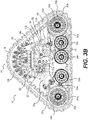
- the attachment assembly 100 includes a plate 102, leading and trailing pivots 130a, 130b ( Figures 3B and 4 ) extending laterally outwardly from the attachment assembly 100 through the plate 102.
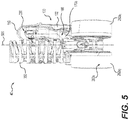
- the track system 40 further includes a multi-member frame assembly 160 disposed laterally outwardly from the attachment assembly 100 ( Figure 5 ).
- the multi-member frame assembly 160 includes a leading frame member 170a pivotably connected to the attachment assembly 100 via the leading pivot 130a for pivoting about a leading pivot axis 180a ( Figure 3B ).
- the multi-member frame assembly 160 also includes a trailing frame member 170b pivotably connected to the attachment assembly 100 via the trailing pivot 130b for pivoting about a trailing pivot axis 180b ( Figure 3B ).
- the multi-member frame assembly 160 also includes a leading wheel-bearing frame member 200a pivotably connected to the leading frame member 170a, and a trailing wheel-bearing frame member 200b pivotably connected to the trailing frame member 170b.
- a trailing support wheel assembly 210 is pivotably connected to the trailing wheel-bearing frame member 200b.
- the track system 40 further includes a damper 230 (in this embodiment a shock absorber) interconnecting the leading frame member 170a and the trailing frame member 170b.
- a leading idler wheel assembly 260a is rotatably connected to the leading wheel-bearing frame member 200a and a trailing idler wheel assembly 260b is rotatably connected to the trailing wheel-bearing frame member 200b.
- a plurality of support wheel assemblies 290a, 290b, 290c are disposed intermediate the leading idler wheel assembly 260a and the trailing idler wheel assembly 260b.
- the support wheel assembly 290a is rotatably connected to the leading wheel-bearing frame member 200a.
- the support wheel assemblies 290b, 290c are rotatably connected to the trailing support wheel assembly 210.
- the track system 40 further includes a gearbox 320 having an input shaft 322 operatively connectable to the drive shaft 64 of the vehicle 60.
- the gearbox 320 also includes an output shaft 324.
- the track system 40 further includes a sprocket wheel 350 operatively connected to the output shaft 324, and an endless track 380 extending around the sprocket wheel 350, the leading idler wheel assembly 260a, the trailing idler wheel assembly 260b, and the plurality of support wheel assemblies 290a, 290b, 290c.
- the endless track 380 is drivable by the sprocket wheel 350.
- the endless track 380 is an endless polymeric track 380.
- the endless track 380 has an inner surface 382 engaging the leading idler wheel assembly 260a, the trailing idler wheel assembly 260b, the plurality of support wheel assemblies 290a, 290b, 290c and the sprocket wheel 350.
- the inner surface 382 has lugs 384 disposed on a central portion of the inner surface 382.
- the endless track 380 also has an outer surface 386 with a tread 388 configured for ground engagement.
- the tread 388 can be varied according to the type of vehicle on which the track system 40 is to be used with and/or the type of ground surface on which the vehicle will be driven.
- the endless track 380 may be constructed of a wide variety of materials and structures including metallic components known in track systems. The specific properties and materials of the endless track 380 are not central to the present technology and will not be described in detail.
- the endless track 380 has a leading edge 390, a ground engaging edge 392 and a trailing edge 394.
- the "edges" of the endless track 380 are the segments of the endless track 380.
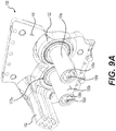
- the plate 102 has an inward face 104 and outward face 106 ( Figures 9A and 9B ).
- a bolt pattern 108 is defined on the inward face 104 of the plate 102.
- the holes 110 of the bolt pattern 108 are threaded bore holes, but could be through holes in other embodiments.
- the bolt pattern 108 that is illustrated is exemplary only and can be varied according to the type of vehicle 60 with which the track system 40 is to be used.
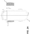
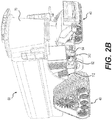
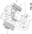
- a compatible bolt pattern 74 is defined on the chassis 62 of the vehicle 60 ( Figures 2C and 2D ).
- the attachment assembly 100 is connected to the chassis 62 of the vehicle 60 through fasteners 112 extending from the chassis 62 and engaging the thread of the holes 110.
- the weight of the vehicle 60 is supported by the clamping load provided by the fasteners 112 extending between the chassis 62 and the attachment assembly 100 of the track system 40.
- the configuration of the attachment assembly 100 and of the rest of the track system 40 is such that the chassis 62 of the vehicle 60 has the same ground clearance as when the vehicle 60 is equipped with wheels and tires in place of the track system 40. Accordingly, under certain conditions, the overall height of the vehicle 60 from ground surface is the same when the track system 40 is used in place of wheels and tires.
- the plate 102 has leading and trailing pivot receiving holes 120a, 120b therein.
- the leading and trailing pivot receiving holes 120a, 120b are shaped and dimensioned to receive the leading and trailing pivots 130a, 130b.
- the pivot receiving holes 120a, 120b extend between the inward and outward faces 104, 106 of the plate 102.
- the plate 102 has a reinforced portion 122 in a region adjacent to the pivot receiving holes 120a, 120b to reduce bending of the pivots 130a, 130b.
- the reinforced portion 122 has a thickness that is greater than that of the remainder of the plate 102. In other embodiments, the reinforced portion 122 could be otherwise configured or omitted.
- the leading and trailing pivots 130a, 130b extend through the corresponding leading and trailing pivot receiving holes 120a, 120b.
- the pivots 130a, 130b extend horizontally and perpendicular to the attachment plate 102.
- the plate 102 has shoulder recesses 124a, 124b defined on the inward face 104 around each one of the leading and trailing pivot receiving holes 120a, 120b.
- the plate 102 also has countersinks 126a, 126b defined on the inward face 104 around each one of the leading and trailing pivot receiving holes 120a, 120b.
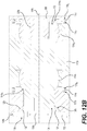
- the leading and trailing pivots 130a, 130b each have a shoulder portion 132 ( Figures 12A and 12B ) at their respective inward end 134, opposite to their outward end 136.
- Each shoulder portion 132 is shaped and dimensioned to abut in the corresponding shoulder recess 124a, 124b when the leading and trailing pivots 130a, 130b are inserted in the leading and trailing pivot receiving holes 120a, 120b ( Figure 12B ).
- a fillet 133 is provided between the shoulder portion 132 and the inward end 134 of each pivot 130a, 130b. The radius of the fillet 133 can be selected to reduce stress concentrations in regions adjacent to the inward end 134.
- Loads on the chassis 62 of the vehicle are transferred to the plate 102 when the plate 102 is connected to the chassis 62 with the fasteners 112. They are then transferred to the leading and trailing pivots 130a, 130b and then to the leading and trailing frame members 170a, 170b, and so on.
- Other configurations of the plate 102 and pivots members 130a, 130b are contemplated, in other embodiments.
- the pivots 130a, 130b could further include a countersunk portion at their inward end 134. The countersunk portion could be shaped and dimensioned to abut a corresponding one of the countersinks 126a, 126b.
- the pivots 130a, 130b could be integrally formed with the plate 102.
- fasteners 138a, 138b extend axially through the leading and trailing pivots 130a, 130b to be fastened to a housing 326 of the gearbox 320.
- the fasteners 138a, 138b engaged with threaded connection holes 328a, 328b defined in the housing 326 of the gearbox 320 ( Figures 12B and 15A - the figures are schematic and as such do not show the threads of the fasteners 138a, 138b nor those of the threaded connection holes 328a, 328b).
- the housing 326 is fastened to the attachment assembly 100 via the fasteners 138a, 138b.
- the fasteners 138a, 138b also hold in place the leading and trailing pivots 130a, 130b with respect to the plate 102 when the shoulder portions 132 of the pivots 130a, 130b abut the recessed shoulder portions 124a, 124b ( Figure 9B ) of the plate 102.
- the fasteners 138a, 138b extend coaxially with the leading and trailing pivot axes 180a, 180b.
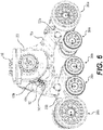
- the housing 326 is also connected to the attachment assembly 100 via a bracket 150 connected to the plate 102, as best seen in Figures 5 , 6 and 10 .
- the bracket 150 extends above and around the damper 230.
- the damper 230 is disposed laterally inwardly from the housing 326 of the gearbox 320.
- the bracket 150 offers some protection to the damper 230 from debris or projections that could impact the damper 230 during operation of the vehicle 60 equipped with the track system 40.
- Other configurations of the bracket 150 are contemplated.
- the bracket 150 could be integrally formed with the plate 102 or omitted.
- the leading pivot axis 180a is disposed above the trailing pivot axis 180b, as best seen in Figures 8 to 10 .
- Such configuration has been found to assist in reducing vibrations in the track system 40 and to assist in reducing the variations in the perimeter of the endless track 380.
- Other configurations are contemplated.
- the leading and trailing pivot axes 180a, 180b could be at a same height with respect to the ground surface.
- the leading and trailing pivot axes 180a, 180b could be disposed one above the other.
- the positioning of the leading and trailing pivot axes 180a, 180b is determined by the bolt pattern 108 since the positioning of the leading and trailing pivot 130a, 130b and of the reinforced portion 122 adjacent thereto should not interfere with the bolt pattern 108.
- a stop 152 is integrally formed in the plate 102 of the attachment assembly 100 ( Figure 9A ).
- the stop 152 extends laterally outwardly from the outward face 106 of the plate 102.
- the stop 152 extends through an aperture 172b defined in the trailing frame member 170b.
- the stop 152 is structured and dimensioned to limit the pivotal movement of the trailing frame member 170b about the trailing pivot axis 180b.
- the aperture 172b is arcuate, but it could be otherwise. In some embodiments, the center of the arc of the aperture 172b coincides with the trailing pivot axis 180b.
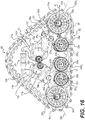
- upper and lower walls 173b, 175b ( Figures 7 and 16 ) of the aperture 172b can abut the stop 152 and thus limit the pivotal movement of the trailing frame member 170b.
- the stop 152 and/or the aperture 172b could be otherwise configured in other embodiments and limit the pivotal movement of the trailing frame member 170b to a lesser or greater extent than the one illustrated.
- the stop 152 is further connected to the housing 326 using fasteners 340 ( Figures 4 and 6 ). In some embodiments, the stop 152 is only connected to the attachment assembly 100.
- the stop 152 is a separate component from the plate 102 and is connected thereto using fasteners and/or bonding techniques.
- the stop 152 has a coating made of a compliant material such as rubber or an elastomer, or has rubber parts attached thereto.
- the stop 152 deflects along its length when contacted by the trailing frame member 170b.
- the trailing frame member 170b does not have an aperture 172b defined therein and one or more stops extending from the outward face 106 of the plate 102 could engage the trailing frame member 170b on a top or bottom sidewall thereof.
- the stop 152 could be omitted.
- leading and trailing frame members 170a, 170b will be described.
- the leading and trailing frame members 170a, 170b are pivotably connected to the attachment assembly 100 as they are supported by the leading and trailing pivots 130a, 130b.
- the leading and trailing frame members 170a, 170b are disposed laterally outwardly from the attachment assembly 100 ( Figure 5 ).
- spherical bearings are disposed between each pivot member 130a, 130b and each frame member 170a, 170b.
- the configuration of the pivot, frame member and spherical bearings will be described with reference to the trailing frame member 170b, as, in this embodiment, the leading frame member 170a has a similar configuration.
- spherical bearings 174b 1 , 174b 2 are disposed between the trailing frame member 170b and the trailing pivot 130b.
- the spherical bearings 174b 1 , 174b 2 are spaced apart along the length of the pivot 130b, one proximate the inward end 134 and the other proximate the outward end 136 thereof.
- the spherical bearings 174b 1 , 174b 2 could be replaced by bushings, plain bearings or tapper rollers disposed between the pivot 130b and the trailing frame member 170b.
- a seal 176b is disposed between the trailing frame member 170b and the attachment assembly 100, proximate the inward end 134 of the pivot 130b.
- Grooves 177b 1 , 177b 2 are defined in the plate 102 and in the inward face of the trailing frame member 170b to receive a portion of the seal 176b.
- a similar configuration is found on the leading frame member 170a proximate the leading pivot 130a.
- a seal 178b is disposed between the leading and trailing frame members 170a, 170b and the housing 326 proximate to the outward end 136 of the pivots 130a, 130b.
- Grooves 179b 1 , 179b 2 are defined in the outward face of the trailing frame member 170b and the inward face of the housing 326 to receive a portion of the seal 178b.
- a similar configuration is found on the leading frame member 170a proximate the leading pivot 130a.
- the leading and trailing frame members 170a, 170b do not contact the plate 102 nor the housing 326 as there is a gap 181b 1 between the bearing 174b 1 and the plate 102.
- Another gap 181b 2 exists between the bearing 174b 2 and the housing 326.
- the gap 181b 1 is smaller than the gap 181b 2 .
- the leading and trailing frame members 170a, 170b are movable axially on the pivots 130a, 130b respectively.
- the leading frame member 170a has an aperture 172a defined therein.
- the input shaft 322 of the gearbox 320 extends laterally inwardly through the aperture 172a ( Figure 2D ) for operative connection to the drive shaft 64 of the vehicle 60.
- the input shaft 322 extends completely through the aperture 172a for operative connection to the drive shaft 64.
- the input shaft 322 and the drive shaft 64 are operatively connected through a constant velocity joint 342 ( Figures 2B to 2D ).
- the input shaft 322 and the drive shaft 64 could be operatively connected otherwise.
- the input shaft 322 and the drive shaft 64 could be coaxial and operatively connected together using a splined sleeve or a coupling.
- the aperture 172a is shaped and dimensioned so as to allow pivotal motion of the leading frame member 170a notwithstanding the presence of the input shaft 322 and/or the drive shaft 64 extending through the aperture 172a.
- the aperture 172a is shaped and dimensioned such that the input shaft 322 and/or the drive shaft 64 extending through the aperture 172a are prevented from contacting the upper and lower walls 173a, 175a of the aperture 172a ( Figures 10 and 16 ) when the leading frame member 170a pivots.
- the aperture 172a is arcuate in this embodiment, but the aperture 172a could be otherwise in other embodiments. In some embodiments, the center of the arc of the aperture 172a coincides with the leading pivot axis 180a. In some embodiments, the aperture 172a extends until one of the upper and lower sidewalls of the frame member 170a and forms a slot in the frame member 170a.
- the gearbox 320 could be configured such that the input shaft 322 extends through the aperture 172b defined in the trailing frame member 170b and the attachment assembly 100 could be configured such that the stop 152 extends through the aperture 172a defined in the leading frame member 170a.
- the drive shaft 64 of the vehicle 60 does not bear a material portion of the weight of the vehicle 60 but only transmits rotational forces to the gearbox 320 via the operative connection with the input shaft 322.
- the output shaft 324 of the gearbox 320 does not bear a material portion of the weight of the vehicle 60 either.
- the output shaft 324 is subjected to bending forces due to the tension present in the endless track 320 and to rotational forces transmitted by the input shaft 322.
- the leading and trailing frame members 170a, 170b each have upper and lower portions 182a, 182b, 184a, 184b.
- the upper portions 182a, 184a extend above the corresponding pivot axes 180a, 180b and the lower portions extend below the pivot axes 180a, 180b.
- the damper 230 is rotatably connected to the upper portions 182a, 182b of the leading and trailing frame members 170a, 170b.
- the damper 230 includes a hydro-pneumatic cylinder 232 and a coil spring 234. The damper 230 biases the upper portions 182a, 182b of the leading and trailing frame members 170a, 170b away from each other.
- the coil spring 234 When the track system 40 supports the weight of the vehicle 60, the coil spring 234 is deformed (i.e. compressed) and the cylinder 232 provides for a damped pivotal motion of the leading and trailing frame members 170a, 170b with respect to each other.
- damper 230 The positioning of the damper 230 between the upper portions 182a, 182b of the leading and trailing frame members 170a, 170b allows for a long stroke of the cylinder 232 of the damper 230.
- the damping action of the damper 230 is generally more refined than in conventional track systems where the stroke of a damping cylinder is shorter.
- a spring rate of the coil spring 234 is also decreased compared to conventional track systems where the stroke of the damper is shorter.
- Such configuration provides for a smoother damping action of the damper 230 and may reduce the risks of fully compressing the damper 230. Under certain conditions, vibrations that are due to the surface of the ground on which the track system 40 travels and transferred to the leading and trailing frame members 170a, 170b are dampened by the damper 230.
- the stop 152 limits the pivotal motion of the trailing frame member 170b, and the pivotal motion of the leading frame member 170a is limited by the stroke of the cylinder 232.
- the damper 230 has variable damping characteristics as described in commonly owned International Patent Application No. PCT/CA2016/050418, filed April 11, 2016 , entitled “Progressive Damping System for a Track System” and published as WO 2016/161527 .
- the gearbox 320 is disposed outwardly from the leading and trailing frame members 170a, 170b.
- the gearbox 320 is disposed inwardly from the sprocket wheel 350. Teeth 352 of the sprocket wheel 350 pass around the gearbox 320 when the sprocket wheel 350 is rotated.
- the input shaft 322 is connected to an input gear 330 located inside the housing 326 of the gearbox 320.
- the input shaft 322 and the input gear 330 rotate about an axis 334.
- the input gear 330 drives an output gear 332 connected to the output shaft 324.
- the output gear 332 is also located inside the housing 326 of the gearbox 320.
- the output shaft 324 and the output gear 332 rotate about an axis 336.
- the axes 334, 336 are parallel and offset, but could be coaxial in other embodiments.
- the engagement of the input gear 330 and the output gear 332 is direct, but a chain or belt could be used in other embodiments to transmit rotational movement from the input gear 330 to the output gear 332.
- the output shaft 324 is connected to the output gear 332 and extends laterally outwardly from the housing 326.
- the output shaft 324 has a flanged portion 325. ( Figure 15C ).
- the sprocket wheel 350 is connected to the flanged portion 325 of the output shaft 324 using fasteners 354 ( Figure 4 ).
- the teeth 352 of the sprocket wheel 350 engage the lugs 384 defined on the inner surface 382 of the endless track 380 and drive the endless track 380.
- the track system 40 is a "positive drive" track system.
- leading wheel-bearing frame member 200a is directly pivotably connected to the lower portion 184a of the leading frame members 170a about an axis 202a.
- trailing wheel-bearing frame member 200b is directly pivotably connected to the lower portion 184b of the trailing frame members 170b about an axis 202b ( Figure 17 ).
- the track system 40 is shown in a rest position.
- the nominal load of the track system corresponds to the track system being attached to the vehicle with the track system bearing its ordinary portion of the weight of the vehicle 60 when the vehicle 60 is at its tare weight, with no attachments at the front or rear and no payload in its container or tank.
- the axis 202b is above the axis 202a. Having the axis 202b above the axis 202a has been found to reduce the variations of the perimeter of the endless track 380 under certain conditions.
- idler wheels 262a 1 , 262a 2 of the leading idler wheel assembly 260a rotate about an axis 264a defined by an axle assembly 266a rotatably connecting the leading idler wheel assembly 260a to the leading wheel-bearing frame member 200a.
- Idler wheels 262b 1 , 262b 2 of the trailing idler wheel assembly 260b rotate about an axis 264b defined by an axle assembly 266b rotatably connecting the trailing idler wheel assembly 260b to the trailing wheel-bearing frame member 200b.
- the idler wheels 262a 1 , 262b 1 are disposed inwardly of the lugs 384 of the endless track 380, and the idler wheels 262a 2 , 262b 2 are disposed outwardly of the lugs 384 of the endless track 380.
- the endless track 380 is guided between the inwardly disposed idler wheels 262a 1 , 262b 1 and the outwardly disposed idler wheels 262a 2 , 262b 2 along the ground engaging edge 392 of the endless track 380 ( Figure 16 ).
- the idler wheels 262a 1 , 262a 2 , 262b 1 , 262b 2 have a same diameter, but in other embodiments the diameter of the leading and idler wheels 262a 1 , 262a 2 , 262b 1 , 262b 2 could differ.
- the leading wheel-bearing frame member 200a includes a tensioner 410 having first and second ends 412, 414.
- the first end 412 is rotatably connected to the leading wheel-bearing frame member 200a at a proximal tensioning pivot 416.
- the proximal tensioning pivot 416 includes a spherical joint (not shown).
- a wheel linkage 418 is rotatably connected to the leading wheel-bearing frame member 200a at an axis 420 that is offset from the axis 264a.
- the second end 414 of the tensioner 410 is rotatably connected to the wheel linkage 418 at a distal tensioning pivot 422 which is offset from the axis 264a.
- the distal tensioning pivot 422 includes a spherical joint and the proximal tensioning pivot 416 does not. In some embodiments, both the proximal and distal tensioning pivots 416, 422 include a spherical joint.
- the leading axle assembly 266a is operatively connected to the wheel linkage 418.
- the distal tensioning pivot 422 and the axis 420 are angularly displaced around the axis 264a such that the wheel linkage 418 forms a lever with the axis 420 being the fulcrum thereof.
- the tensioner 410 could be included on the trailing wheel-bearing frame member 200b.
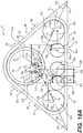
- the action of the tensioner 410 and the wheel linkage 418 bias the leading axle assembly 266a and the leading idler wheel assembly 260a toward the forward end of the track system 40 with a biasing force 501 ( Figures 16 and 18A ).
- the endless track 380 opposes the biasing force 501 provided by the action of the tensioner 410 and the wheel linkage 418 and tension 502, 504 ( Figures 16 and 18A ) appears in the leading edge 390 and the ground-engaging edge 392 of the endless track 380.
- the tensioner 410 is used to reduce the variations in the perimeter of the endless track 380 due to the pivoting of the leading and trailing frame members 170a, 170b and wheel-bearing frame members 200a, 200b.
- the tensioner 410 is configured to apply less biasing force 501 and/or contract so as to reduce variation in the perimeter of the endless track 380.
- the tensioner 410 is configured to apply more biasing force 501 and/or extend to provide for adequate tension forces 502, 504 in the endless track 380.
- the tensioner 410 is a dynamic tensioning device as described in International Patent Application No. PCT/CA2016/050419, filed April 11, 2016 , entitled “Dynamic Tensioner Locking Device for a Track System and Method Thereof', and published as WO 2016/161528 .
- the leading wheel-bearing frame member 200a also includes a tracking adjustment system 430.
- the tracking adjustment system 430 includes a support 432 that is pivotable with respect to the leading wheel-bearing frame member 200a about an axis 434.
- the axle assembly 266a is rotatably connected to the support 432.
- Adjustment screws 436 1 , 436 2 are connected to the leading wheel-bearing frame member 200a, rearwardly offset of the axis 434.
- a portion (not shown) of the support 432 extends rearward of the axis 434.
- each one of the adjustment screws 436 1 , 436 2 abuts the portion of the support 432 and each one of the adjustment screws 436 1 , 436 2 can be adjusted to pivot the support 432 inwardly or outwardly.
- the leading idler wheel assembly 260a can provide for tracking adjustment of the endless track 380 as it is driven around the sprocket wheel 350, the leading idler wheel assembly 260a, the trailing idler wheel assembly 260b, and the plurality of support wheel assemblies 290a, 290b, 290c.
- the support wheel assembly 290a includes support wheels 292a 1 , 292a 2 that are rotatably connected to the leading wheel-bearing frame member 200a via an axle assembly 294a.
- the support wheels 292a 1 , 292a 2 rotate about an axis 296a.
- the support wheel assemblies 290b, 290c include support wheels 292b 1 , 292b 2 , 292c 1 , 292c 2 that are rotatably connected to the trailing support wheel assembly 210 via axle assemblies 294b, 294c.
- the support wheels 292b 1 , 292b 2 rotate about an axis 296b and the support wheels 292c 1 , 292c 2 rotate about an axis 296c.
- the trailing support wheel assembly 210 includes a support wheel frame member 212 ( Figure 17 ).
- the support wheel member 212 has a body that is longitudinally elongated.
- the support wheel member 212 extends above the lugs 384 of the ground-engaging edge 392 of the endless track 380.
- the support wheel frame member 212 pivots about an axis 216 with respect to the trailing wheel-bearing frame member 200b.
- the support wheel assemblies 290b, 290c are indirectly pivotably connected to the trailing wheel-bearing frame member 200b.
- the support wheel assembly 290b is disposed forward of the axis 216, and the support wheel assembly 290c is disposed rearward of the axis 216.
- the endless track 380 is guided between the inwardly disposed support wheels 290a 1 , 290b 1 , 290c 1 and the outwardly disposed support wheels 290a 2 , 290b 2 , 290c 2 as the lugs 384 of the ground-engaging edge 392 of the endless track 380 extend therebetween.
- the support wheels 292a 1 , 292a 2 , 292b 1 , 292b 2 , 292c 1 , 292c 2 have a smaller diameter than that of the idler wheels 262a 1 , 262a 2 , 262b 1 , 262b 2 .
- the leading wheel bearing member 200a could include a support wheel frame member pivotably connected thereto and including leading support wheels.
- the various components of the track system 40 are made of conventional materials (e.g. metals and metal alloys in most cases, such as steel) via conventional manufacturing processes (e.g. casting, molding, etc.).
- the present technology does not require any specific materials nor methods of manufacture.
- the present technology merely requires that each component be suitable for the purpose for which it is intended and the use to which it is to be put. Any material(s) or method(s) of manufacture which produce such components may be used in the present technology.
- a plane 500 extends parallel to a longitudinal direction of the track system 40 and extends parallel to a height direction of the track system 40.
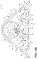
- Figures 16 to 18C illustrate the track system 40 in a plane view that is parallel to the plane 500.
- the pivot axes 180a, 180b and the axes 202a, 202b, 216, 264a, 264b, 296a, 296b, 296c are perpendicular to the plane 500.
- the leading pivot axis 180a and the axis 202a are spaced apart by a longitudinal distance 600a defined in the plane 500.
- the trailing pivot axis 180b and the axis 202b are spaced apart by a longitudinal distance 600b defined in the plane 500.
- the longitudinal distance 600a is greater than the longitudinal distance 600b.
- the leading frame member 170a defines a lever arm between the leading pivot axis 180a and the axis 202a that is greater than the lever arm defined by the trailing frame member 170b between the trailing pivot axis 180b and the axis 202b.
- the trailing frame member 170b supports a greater load than the leading frame member 170a since the lever arm defined by the trailing frame member 170b between the trailing pivot axis 180b and the axis 202b is shorter.
- the trailing wheel-bearing frame member 200b has more support wheel assemblies indirectly rotatably connected thereto than the leading wheel-bearing frame member 200a (namely the support wheel assemblies 290b, 290c rotatably connected to the trailing support wheel assembly 210).
- the axes 296a, 202a are spaced apart in a longitudinal direction by a longitudinal distance 620a defined in the plane 500.
- the axes 264a, 202a are spaced apart in a longitudinal direction by a longitudinal distance 630a defined in the plane 500.
- the distance 620a is shorter than the distance 630a.
- a portion of the weight of the vehicle 60 is transferred at the axis 202a from the leading frame member 170a to the leading wheel-bearing member 200a.
- the leading support wheel assembly 290a supports more load than the leading idler wheel assembly 260a.
- the axes 216, 202b are spaced apart in a longitudinal direction by a longitudinal distance 620b defined in the plane 500.
- the axes 264b, 202a are spaced apart in a longitudinal direction by a longitudinal distance 630b defined in the plane 500.
- the distance 620b is shorter than the distance 630b.
- a portion of the weight of the vehicle 60 is transferred at the axis 202b from the trailing frame member 170b to the trailing wheel-bearing member 200b.
- the support wheel frame member 212 and the support wheel assemblies 290b, 290c support more load than the trailing idler wheel assembly 260b.
- the axes 296b, 216 are spaced apart in a longitudinal direction by a longitudinal distance 640b defined in the plane 500. Similarly, the axes 296c, 216 are spaced apart in a longitudinal direction by a longitudinal distance 640c defined in the plane 500. In this embodiment, the distances 640b, 640c are equal. As such, the trailing support wheel assemblies 290b, 290c support equal loads.
- a designer of track systems is able to set a distribution of pressure applied to the endless track 380 by the leading and trailing idler wheel assemblies 260a, 260b and the support wheel assemblies 290a, 290b, 290c to meet the requirements of a particular application.
- the distances 600a, 600b, 620a, 620b, 630a, 630b, 640b, 640c, the diameter and width of the idler and support wheel assemblies 260b, 290a, 290b, 290c are selected to equalize the pressure applied to the endless track 380 by the leading support wheel assembly 290a, the trailing support wheel assemblies 290b, 290c and the trailing idler wheel assembly 260b.
- the pressure applied to the endless track 380 by the leading idler wheel assembly 260a is less than the pressure applied by each one of the leading support wheel assembly 290a, the trailing support wheel assemblies 290b, 290c and the trailing idler wheel assembly 260b.
- the distances 600a, 600b, 620a, 620b, 630a, 630b, 640b, 640c, the diameter and width of the idler and support wheel assemblies 260a, 260b, 290a, 290b, 290c could be selected to equalize the pressure applied to the endless track 380 by the support wheel assemblies 290a, 290b, 290c.
- the distances 600a, 600b, 620a, 620b, 630a, 630b, 640b, 640c, the diameter and width of the idler and support wheel assemblies 260a, 260b, 290a, 290b, 290c could be selected to equalize the pressure applied to the endless track 380 by the leading and trailing idler wheel assemblies 260a, 260b.
- the leading wheel-bearing frame member 200a carries the resultant force 510 to the axis 202a along a line 550a extending between the axis 264a and the axis 202a, the line 550a being shown as a dashed line in Figures 16 and 18A to 18E .
- the line 550a is colinear with the bisector 702a, but it could be otherwise in other embodiments as other configurations of the leading wheel bearing frame member 200a are contemplated. Having the resultant force 510 passing at the axis 202a has the effect of preventing the generation of a torque that is applied to the leading wheel-bearing member 200a about the axis 202a.
- the line 550a and the bisector 702a pass below the leading pivot axis 180a.
- the bisector 702a and the pivot axis 180a are spaced apart by a shortest distance 552a defined in the plane 500.
- the distance 552a defines a lever arm between the bisector 702a and the pivot axis 180a.
- a torque 540a is applied to the leading frame member 170a about the leading pivot axis 180a. From the perspective of Figure 18A , the torque 540a has the effect of inducing a clockwise rotation of the leading frame member 170a about the pivot axis 180a.
- the torque 540a also has the effect of increasing the load supported by the leading support wheel assembly 290a and the load supported by the leading idler wheel assembly 260a.
- tension forces 504 are applied on the ground-engaging edge 392 of the endless track 380 proximate to the trailing idler wheel assembly 260b.
- Tension forces 522 also appear in the trailing edge 394 of the endless track 380 and oppose tension forces 524, 526 appearing in the endless track 380 adjacent to the sprocket wheel 350.
- tension forces 502, 504, 520, 522, 524, 526 are equal.
- a resultant force 530 (e.g. the combination of tension forces 520, 522) is applied to the trailing idler wheel assembly 260b and the resultant force 530 is applied at the axis 264b.
- the trailing and ground engaging edges 394, 392 of the endless track 380 form an angle 700b.
- the resultant force 530 is colinear with a bisector 702b of the angle 700b.
- the trailing wheel-bearing frame member 200b carries the resultant force 530 to the axis 202b along a line 550b extending between the axis 264b and the axis 202b, shown as a dashed line in Figures 16 and 18A to 18E .
- the line 550b is colinear with the bisector 702b, but it could be otherwise in other embodiments as other configurations of the trailing wheel bearing frame member 200b are contemplated.
- Having the resultant force 530 passing at the axis 202b has the effect of preventing the generation of a torque that is applied to the trailing wheel-bearing member 200b about the axis 202b.
- the line 550b and the bisector 702b pass below the trailing pivot axis 180b.
- the bisector 702b and the pivot axis 180b are spaced apart by a shortest distance 552b defined in the plane 500.
- the distance 552b defines a lever arm between the bisector 702b and the pivot axis 180b.
- a torque 540b is applied to the trailing frame member 170b about the trailing pivot axis 180b. From the perspective of Figure 18A , the torque 540b has the effect of inducing a counter-clockwise rotation of the trailing frame member 170b about the pivot axis 180b. The torque 540b also has the effect of increasing the load supported by the support wheel assemblies 290b, 290c and the load supported by the trailing idler wheel assembly 260b.
- the distance 552b is greater than the distance 552a.
- the magnitude of the resultant force 530 is greater than the resultant force 510.
- the torque 540b has a greater magnitude than the torque 540a.
- a net torque e.g. the combination of torques 540a, 540b having the same direction than torque 540b is applied to the track system 40.
- the bisector 702a could pass above the leading pivot axis 180a. In such cases, the distance 552a could be greater than the distance 552b as the net torque applied to the track system 40 would still have the same direction as torque 540b.
- the track system 40 When the track system 40 is driven, the pressures applied to the endless track 380 under the leading idler wheel assembly 260a and leading support wheel assembly 290a are decreased, and the pressures applied to the endless track 380 under the support wheel assemblies 290b, 290c and trailing idler wheel assembly 260b are increased. As a result, under certain conditions, the track system 40 has a reduced tendency to pitch negatively, especially when driven on soft grounds.
- heat generation and wear of the outer surface 386 ( Figure 4 ) of the endless track 380 are reduced when comparing the track system 40 to conventional track systems attached to the same vehicle 60 for the following reasons.
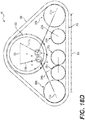
- Figures 18B , 18C , 18D and 18E illustrate different positions of the track system 40 when stationary.
- the track system 40 is shown with the damper 230 fully compressed. Such configuration would be found when the track system 40 supports a load that is greater than the nominal load.
- the track system 40 is shown with the damper fully extended. Such configuration would be found when the track system 40 supports a load that is smaller than the nominal load.
- the track system 40 maintains its reduced tendency to pitch negatively when it is driven, regardless of the load of the vehicle 60.
- the leading idler wheel assembly 260a when the damper 230 is fully compressed, the leading idler wheel assembly 260a is spaced apart from the trailing idler wheel assembly 260b, by a distance 800 (measured between the axes of rotation of each of the idler wheel assemblies 260a, 260b).
- the leading idler wheel assembly 260a when the damper 230 is fully extended, the leading idler wheel assembly 260a is spaced apart from the trailing idler wheel assembly 260b, by a distance 800 (measured between the axes of rotation of each of the idler wheel assemblies 260a, 260b).
- the distance 800 in Figure 18D is greater than the distance 800 in Figure 18E .
- the track 380 has a ground-contacting area that increases in size as a load borne by the track system 40 increases (and the damper compresses).
- the pivoting of the leading and trailing wheel-bearing members 200a, 200b, and of the leading and trailing frame members 170a, 170b has the effect of reducing vertical displacements of the leading and trailing pivots 130a, 130b. Accordingly, vertical displacements of the chassis 62 of the vehicle 60 are reduced. Notably, at certain speed regimes, the pivoting of the leading and trailing wheel-bearing members 200a, 200b alone is sufficient to reduce the vertical displacements of the leading and trailing pivots 130a, 130b.
Landscapes
- Engineering & Computer Science (AREA)
- Chemical & Material Sciences (AREA)
- Combustion & Propulsion (AREA)
- Transportation (AREA)
- Mechanical Engineering (AREA)
- Body Structure For Vehicles (AREA)
- Platform Screen Doors And Railroad Systems (AREA)
- Arrangement Or Mounting Of Propulsion Units For Vehicles (AREA)
- Handcart (AREA)
Description
- The present application claims priority to United States Provisional Patent Application Serial No.
62/353,138, filed June 22, 2016 - The present technology relates to track systems for vehicles.
- Certain vehicles, such as, for example, agricultural vehicles (e.g., harvesters, combines, tractors, etc.) and construction vehicles (e.g., bulldozers, front- end loaders, etc.), are used to perform work on ground surfaces that are soft, slippery and/or uneven (e.g., soil, mud, sand, ice, snow, etc.).
- Conventionally, such vehicles had have large wheels with tires on them to move the vehicle along the ground surface. Under certain conditions, such tires may have poor traction on some ground surfaces and, as these vehicles are generally heavy, the tires may compact the ground surface in an undesirable way owing to the weight of the vehicle. As an example, when the vehicle is an agricultural vehicle, the tires may compact the soil in such a way as to undesirably inhibit the growth of crops. In order to reduce the aforementioned drawbacks, to increase traction and to distribute the weight of the vehicle over a larger area on the ground surface, track systems were developed to be used in place of at least some of the wheels and tires on the vehicles.
- The use of track systems in place of wheels and tires, however, does itself present some inconveniences. One of the drawbacks of conventional track systems is that they tend to decrease the ride comfort experienced by the operator of the vehicle because the air cushion provided by a tire (between each wheel and tire) is not present in such track systems. Thus, vehicles equipped with such track systems in place of wheels and tires are typically subjected to an increased amount of vibration and vertical displacement when driven on uneven surfaces (as compared with the same vehicle having a wheel and tire), because the lack of an air cushion means there is no damping that would otherwise be provided if there were. In addition to potential increased operator discomfort, these vibrations and vertical displacements can potentially lead to premature wear of the vehicle, its component parts, and/or its attached accessories and equipment. Under certain conditions and at certain speeds, vertical displacements and vibrations transferred to the chassis can be so significant that it may be required to slow down the vehicle.
- United States Patent Application Publication No.
2015/0266524 A1 , published September 24, 2015, and entitled "Crawler Vehicle", provides what is purported to be an improved track system in view of the vibrations which may occur with track systems described hereinabove. According to its abstract, the '524 US Publication describes a technology wherein: "A crawler vehicle has a body and at least one left and one right track roller unit. The track roller units are connected to the body via a machine axis. The track roller units comprise a first and a second guide roller as well as a first and a second supporting arm on which the guide rollers are mounted. The first and the second supporting arms of each roller unit are mounted to be pivotable independently of one another about the machine axis." - While the technology described in the '524 US Publication may indeed ameliorate some of the drawbacks of conventional track systems, continued improvement in this area is desirable.
-
US 5,452,949 A discloses a track suspension system for a vehicle having an axle, and a drive wheel of the track suspension system is attached to the axle for engaging and driving a continuous flexible track of the track suspension system. -
DE 29509006 U1 discloses a track system having hydraulic actuators operatively coupled together providing suspension to the vehicle equipped with the track system. -
WO 2016/049760 A1 discloses a track system that decreases the vibrations undergone by a vehicle equipped with the track system. - It is therefore an object of the present technology to ameliorate the situation with respect to at least one of the inconveniences present in the prior art.
- It is also an object of the present invention to provide an improved track system at least in some instances as compared with some of the prior art.
- According to an aspect of the present technology, there is provided a track system for use with a vehicle having a chassis and a drive shaft extending laterally outwardly from the chassis for driving the track system. In the context of the present technology, the "drive shaft" of the vehicle should be understood to be the vehicle drivetrain component that ultimately transmits rotational forces generated by the engine to the ground engaging assembly of the vehicle (e.g. the vehicle vehicle's wheel assembly when such is mounted on the vehicle, or the vehicle's track system when such is mounted on the vehicle, etc.).
- The track system includes an attachment assembly that is connectable to the chassis of the vehicle. The attachment assembly has a leading pivot and a trailing pivot extending laterally outwardly therefrom. In the context of the present technology, the "leading" components of the track system are those that are disposed toward the front end of the vehicle (when the track system is properly installed on the vehicle), and the "trailing" components are those that are disposed toward the rear end of the track vehicle (when the track system is properly installed on the vehicle).
- The track system further includes a multi-member frame assembly disposed laterally outwardly from the attachment assembly. The multi-member frame assembly includes a leading frame member pivotably connected to the attachment assembly via the leading pivot for pivoting about a leading pivot axis and a trailing frame member pivotably connected to the attachment assembly via the trailing pivot for pivoting about a trailing pivot axis. The leading and trailing frame members are structural components of the track system capable of supporting a material portion of the weight of the vehicle. They may be termed "primary" frame members in embodiments where they generally define the overall structure of the track system, or in embodiments where they are the frame members of the track system that first receive the load of the vehicle.
- The track system further includes a leading wheel-bearing frame member at least indirectly pivotably connected to the leading frame member and a trailing wheel-bearing frame member at least indirectly pivotably connected to the trailing frame member. In the context of the present technology, the qualification of a wheel-bearing member as "at least indirectly pivotably connected" includes a wheel-bearing member that is directly pivotably connected to a frame member as well as a wheel-bearing member that is pivotably connected a frame member through an intermediate structure or structures, be they intermediate frame members or otherwise.
- The track system further includes a damper interconnecting the leading frame member and the trailing frame member; a leading idler wheel assembly rotatably connected to the leading wheel-bearing frame member; a trailing idler wheel assembly rotatably connected to the trailing wheel-bearing frame member; and a plurality of support wheel assemblies disposed intermediate the leading idler wheel assembly and the trailing idler wheel assembly.
- The track system further includes a gearbox having an input shaft operatively connectable to the drive shaft of the vehicle and an output shaft; a sprocket wheel operatively connected to the output shaft of the gearbox; and an endless track extending around the sprocket wheel, the leading idler wheel assembly, the trailing idler wheel assembly, and the plurality of support wheel assemblies, and drivable by the sprocket wheel.
- The track system of the present technology is directed towards improving the ride comfort experienced by the operator of the vehicle under certain conditions. For example, improvement to the ride comfort might be perceived by the operator when vertical displacements of the chassis of the vehicle due to the unevenness of the ground surface are reduced and/or when vibrations generated as the vehicle travels over the ground surface are damped before being transferred from the track assembly to the vehicle chassis.
- The leading and trailing frame members of the track system of the present technology define a somewhat scissor-like structure, with each frame member pivots about its respective pivot, and the damper interconnected therebetween. Each one of the leading and trailing wheel-bearing members is in turn pivotably connected to the leading or trailing frame member, respectively. The pivoting of each of these structures, along with the damper, may assist in reducing the vertical displacements and vibrations transferred to the chassis under certain conditions.
- In addition, having a track system with a scissor-like structure may have other advantages in different situations. For example, as the weight of the vehicle increases, e.g. during harvesting operations, the scissor-like structure can open and the ground-contacting portion of the endless track occurs over an increased surface area (i.e. the ground contacting area can increase in size as the load borne by the track system increases - at least for some increases in load - depending on the design of a specific track system). As a result, in some circumstances, the pressure applied to the ground by the endless track (owing to the weight of the vehicle) increases at a lower rate than the weight of the vehicle. In certain embodiments, this will allow a track system of the present technology to bear additional loads as compared with conventional track systems.
- The track system of the present technology, under certain conditions, can provide improved capability when the vehicle to which it is installed is travelling over soft ground. In this respect, in conventional track systems, there is a tendency of the leading edge of the endless track to pitch negatively (also known sometimes as to "dive" in the art) into soft ground when high tractive forces are requested of the track system. Such negative pitching of the leading edge of the track system can lead to track system and/or vehicle damage under some conditions. In some embodiments, the geometrical configuration of the track system of the present technology is constructed with the aim of reducing this tendency under certain conditions.
- Another potential drawback found in many conventional track systems is that the track system is attached in place of the wheel on the vehicle's wheel axle. As the weight of the vehicle is borne via the axle, the weight of the vehicle is transmitted to the sprocket wheel assembly of the track assembly as it is the sprocket wheel assembly that is attached to the axle. This necessitates particular track system design parameters that in some cases are suboptimal. It may also lead to undesirable bending forces in the output shaft as the output shaft is already transmitting rotational forces to the sprocket wheel assembly of the track system. This, in turn, may lead to accelerated wear of the gearbox and of the components thereof, and to higher maintenance cost.
- The track system of the present technology may reduce such issues under certain conditions as a large part of the weight of the vehicle is transferred from the chassis to track system's attachment assembly, then to the leading and trailing frame members, then to the leading and trailing wheel-bearing members and finally to the idler and support wheels and to the endless track. Thus, the sprocket wheel assembly need not (and in most embodiments, does not) bear a material amount of the vehicle weight, and does not need to be designed to do so (in most embodiments).
- Having each of the leading and trailing frame members pivoting about their own pivot (as opposed to about the same pivot), may, depending on the embodiment, provide certain advantages. For example, in some embodiments, the leading and trailing pivots each bear a portion of the load borne by the track system, as opposed to a single pivot having to bear the entirety of the load borne by the system. This splitting of the load may allow for pivots that are less robust (and therefore less expensive and simpler to manufacture) than would be the case if both frame members had to be borne by a single pivot. Additionally, as in many embodiments efficient mechanical packaging is important, the dual pivot design may allow for more efficient packaging than the single pivot design, as a certain minimum contact area between the pivot and the knuckle of the frame member is required, and in many cases a dual pivot design can have more available contact area for a given width of the track system than can a single pivot design. Further, given that this is the case, the pressure between the pivot and the knuckle, in many cases, can be lower in a dual pivot design than in a single pivot design, thus again allowing for the uses of less robust components.
- In some embodiments of the track system of the present technology, at least one of the leading frame member and the trailing frame member has an aperture therein. At least one of the gearbox input shaft and the drive shaft of the vehicle (e.g. the vehicle wheel axle) extends through the aperture. The aperture is shaped and dimensioned so as to allow pivotal motion of the at least one of the leading frame member and the trailing frame member notwithstanding a presence of the at least one of the gearbox input shaft and the drive shaft of the vehicle extending through the aperture. This feature assists in allowing embodiments of track systems of the present technology to be efficiently mechanically packaged, reducing the volume and/or mass of the track system, in embodiments where such is judged to be important.
- In some embodiments, the leading frame member has a first aperture therein, the trailing frame member has a second aperture therein, at least one of the gearbox input shaft and the drive shaft of the vehicle extends through one of the first aperture and the second aperture, the one of the first aperture and the second aperture being shaped and dimensioned so as to allow pivotal motion of the one of the leading frame member and trailing frame member notwithstanding a presence of the at least one of the gearbox input shaft and the drive shaft of the vehicle extending therethrough. A stop extends within the other of the first aperture and the second aperture, the stop being structured and dimensioned to limit pivotal movement of the other of the leading frame member and trailing frame member. This feature may also assist in allowing embodiments of track systems of the present technology to be efficiently mechanically packaged, in embodiments where such is judged to be important.
- In some embodiments, the leading pivot axis is disposed above the trailing pivot axis. In some embodiments, this feature reduces the variations in the effective perimeter of the track (which occur owing to changes in position of the idler wheel(s) and/ support wheels), thus reducing the required operating range of the track tensioner.
- In some embodiments, the leading wheel-bearing frame member is directly pivotably connected to the leading frame member about a first axis. The trailing wheel-bearing frame member is directly pivotably connected to the trailing frame member about a second axis. The first and second axes, the leading pivot axis and the trailing pivot axis extend perpendicularly to a plane extending parallel to a longitudinal direction of the track system, and in a rest position of the track system, the second axis is above the first axis. The rest position is defined as when the track system is attached to the vehicle, the vehicle is in its operating condition, is at rest, is unloaded, and is disposed on flat level ground.
- In some embodiments, the endless track has leading, trailing and ground engaging edges. A first angle is formed between the trailing and ground engaging edges, and a second angle is formed between the leading and ground engaging edges. The first angle has a bisector, and the bisector of the first angle passes below the trailing pivot axis. In some embodiments of track systems of the present technology, this feature may assist in causing in some embodiments of track systems of the present technology a torque to be generated that reduces the tendency of the track system to have a negative pitch.
- In some embodiments, the leading wheel-bearing frame member is directly pivotably connected to the leading frame member about a first axis. The trailing wheel-bearing frame member is directly pivotably connected to the trailing frame member about a second axis. Idler wheels of the leading idler wheel assembly rotate about a third axis. Idler wheels of the trailing idler wheel assembly rotate about a fourth axis. The first, second, third and fourth axes, the leading pivot axis and the trailing pivot axis extend perpendicularly to a plane extending parallel to a longitudinal direction of the track system, and the second and fourth axes intersect the bisector of the first angle.
- In some embodiments, the second angle has a bisector, and the bisector of the second angle passes below the leading pivot axis. In some embodiments of track systems of the present technology, this feature may also assist in causing in some embodiments of track systems of the present technology a torque to be generated that reduces the tendency of the track system to have a negative pitch.
- In some embodiments, the first and third axes intersect the bisector of the second angle.
- In some embodiments, a shortest distance defined in the plane between the bisector of the first angle and the trailing pivot axis is greater than a shortest distance defined in the plane between the bisector of the second angle and the leading pivot axis.
- In some embodiments, the leading wheel-bearing frame member is directly pivotably connected to the leading frame member about a first axis, the trailing wheel-bearing frame member is directly pivotably connected to the trailing frame member about a second axis, and in a rest position of the track system, the second axis is above the first axis.
- In some embodiments, idler wheels of the leading idler wheel assembly rotate about a third axis and idler wheels of the trailing idler wheel assembly rotate about a fourth axis. The first, second, third and fourth axes, the leading pivot axis and the trailing pivot axis extend perpendicularly to a plane extending parallel to a longitudinal direction of the track system. A first line defined in the plane and extending between the first and third axes passes below the leading pivot axis. A second line defined in the plane and extending between the second and fourth axes passes below the trailing pivot axis.
- In some embodiments, a first longitudinal distance defined in the plane between the leading pivot axis and the first axis is greater than a second longitudinal distance defined in the plane between the trailing pivot axis and the second axis.
- In some embodiments, a shortest distance defined in the plane between the second line and the trailing pivot axis is greater than a shortest distance defined in the plane between the first line and the leading pivot axis.
- In some embodiments, a load supported by the trailing wheel-bearing frame member is greater than a load supported by the leading wheel-bearing frame member.
- In some embodiments, a trailing support wheel assembly is pivotably connected to the trailing wheel-bearing frame member about a fifth axis, and a third longitudinal distance defined in the plane between the second axis and the fourth axis is greater than a fourth longitudinal distance defined in the plane between the second axis and the fifth axis.
- In some embodiments, leading support wheels are rotatably connected to the leading wheel-bearing frame member about a sixth axis, and the fourth longitudinal distance is greater than a fifth longitudinal distance defined in the plane between the first axis and the sixth axis.
- In some embodiments, a trailing support wheel assembly is pivotably connected to the trailing wheel-bearing frame member, the trailing support wheel assembly including a support wheel frame member, a pair of forward support wheels rotatably connected to the support wheel frame member, and a pair of rearward support wheels rotatably connected to the support wheel frame member.
- In some embodiments, the leading idler wheel assembly and the trailing idler heel assembly each include idler wheels of a same diameter.
- In some embodiments, the attachment assembly includes a plate having leading pivot receiving hole shaped and dimensioned to receive the leading pivot and a trailing pivot receiving hole shaped and dimensioned to receive the trailing pivot, and the leading pivot extends through the leading pivot receiving hole and the trailing pivot extends through the trailing pivot receiving hole. This feature assists in allowing some embodiments of track systems of the present technology to be easier to manufacture, more solid, and precisely machined (as opposed to when the pivots and the plate are a single unitary article; e.g. a single cast article).
- In some embodiments, the plate has a shoulder recess defined around each of the leading pivot receiving hole and the trailing pivot receiving hole. The leading pivot has a shoulder portion shaped and dimensioned to abut the shoulder recess of the leading pivot receiving hole of the plate, and the trailing pivot has a shoulder portion shaped and dimensioned to abut the shoulder recess of the trailing pivot receiving hole of the plate. This feature assists in allowing some embodiments of track systems of the present technology to be able to better distribute the load on the plate.
- In some embodiments, the track system further includes fasteners extending axially through the leading pivot and the trailing pivot to fasten the gearbox. This feature may also assist in allowing embodiments of track systems of the present technology to be efficiently mechanically packaged, in embodiments where such is judged to be important.
- In some embodiments, the drive shaft is connected to the input shaft of the gearbox via a constant velocity joint. This feature assists in allowing some embodiments of track systems of the present technology to interconnect the vehicle's drive shaft and the gearbox's input shaft when the two are at an angle to one another.
- In some embodiments, the damper is disposed laterally inwardly from the gearbox. This feature may also assist in allowing embodiments of track systems of the present technology to be efficiently mechanically packaged, in embodiments where such is judged to be important.
- In some embodiments, the track system further comprises a bracket connecting the gearbox to the attachment assembly, the bracket extending above and around the damper. The bracket may assist in protecting the damper from environmental debris entering the track system.
- In some embodiments, the stop is connected to the gearbox. This feature may also assist in allowing embodiments of track systems of the present technology to be efficiently mechanically packaged, in embodiments where such is judged to be important.
- In some embodiments, the track has a ground-contacting area that increases in size as a load borne by the track system increases.
- Embodiments of the present technology each have at least one of the above-mentioned object and/or aspects, but do not necessarily have all of them. It should be understood that some aspects of the present technology that have resulted from attempting to attain the above-mentioned object may not satisfy this object and/or may satisfy other objects not specifically recited herein.
- Additional and/or alternative features, aspects, and advantages of embodiments of the present technology will become apparent from the following description, the accompanying drawings, and the appended claims.
- For a better understanding of the present technology, as well as other aspects and further features thereof, reference is made to the following description which is to be used in conjunction with the accompanying drawings, where:
-
Figure 1 is a perspective view taken from a rear, top, right side of a track system being an embodiment of the present technology configured to be operatively connected on a right side of a vehicle; -
Figure 2A is a top view of a vehicle having a track system being an embodiment of the present technology operatively connected on a left side of the vehicle and the track system ofFigure 1 on a right side of, but apart from, the vehicle; -
Figure 2B is a perspective view taken from a front, bottom, right side of the vehicle ofFigure 2A ; -
Figure 2C is another perspective view taken from a front, bottom, right side of the vehicle ofFigure 2A ; -
Figure 2D is an enlarged view ofsection 2D ofFigure 2C ; -
Figure 3A is an elevation view of the left side of the track system ofFigure 1 ; -
Figure 3B is an elevation view of the right side of the track system ofFigure 1 ; -
Figure 4 is an exploded view taken from a front, top, right side of the track system ofFigure 1 ; -
Figure 5 is a front elevation view of the track system ofFigure 1 , with the endless track removed; -
Figure 6 is a perspective view taken from a front, top, right side of the track system ofFigure 1 , with the endless track and the sprocket wheel removed; -
Figure 7 is a perspective view taken from a front, top, right side of the track system ofFigure 6 , with a gearbox removed; -
Figure 8 is a perspective view taken from a front, top, left side of the track system ofFigure 7 , with a leading idler wheel removed; -
Figure 9A is a perspective view taken from a front, top, right side of an attachment assembly of the track system ofFigure 1 ; -
Figure 9B is a perspective view taken from a rear, top, left side of a plate of the attachment assembly ofFigure 9A ; -
Figure 10 is a perspective view taken from a front, top, left side of the track system ofFigure 8 , with the leading and trailing idler wheels removed; -
Figure 11 is a left right elevation view of the track system ofFigure 10 , with a trailing wheel-bearing frame member removed; -
Figure 12A is a cross-sectional view of the track system ofFigure 11 taken alongcross-section line 12A-12A inFigure 11 ; -
Figure 12B is an enlarged view ofsection 12B ofFigure 12A ; -
Figure 13 is a perspective view taken from a rear, bottom, right side of the track system ofFigure 11 , with a trailing frame member removed; -
Figure 14 is a perspective view taken from a rear, top, left side of the track system ofFigure 13 , with a trailing pivot of the attachment assembly removed; -
Figure 15A is a perspective view taken from a rear, top, left side of the gearbox of the track system ofFigure 1 ; -
Figure 15B is a perspective view taken from a rear, top, left side of components of the gearbox ofFigure 15A ; -
Figure 15C is a perspective view taken from a front, top, right side of the components ofFigure 15B ; -
Figure 16 is a right side elevation view of the track system ofFigure 1 , with the sprocket wheel, the gearbox and the attachment assembly removed; -
Figure 17 is a right side elevation view of the track system ofFigure 16 , with the endless track and two trailing support wheels removed; -
Figure 18A is a schematic, right side elevation diagram of the track system ofFigure 1 in a rest position and stationary; -
Figure 18B is a schematic, right side elevation diagram of the track system ofFigure 1 in a fully compressed position; -
Figure 18C is a schematic, right side elevation diagram of the track system ofFigure 1 in a fully extended position. -
Figure 18D is a schematic, right side elevation diagram of the track system of 18B; and -
Figure 18E is a schematic, right side elevation diagram of the track system ofFigure 18C . - With reference to
Figures 1 to 5 , an embodiment of the present technology,track system 40, is illustrated. It is to be expressly understood that thetrack system 40 is merely embodiment of the present technology. - The
track system 40 is for use with avehicle 60 having achassis 62 and adrive shaft 64 extending laterally outwardly from thechassis 62 for driving thetrack system 40. Thechassis 62 supports the components of thevehicle 60, such as thecabin 70, the engine, thegearbox 72 and other drivetrain components (not shown). In this embodiment, thedrive shaft 64 is the drivetrain component that transmits the driving force from the engine andgearbox 72 of thevehicle 60 to thetrack system 40, i.e. thedrive shaft 64 is the output shaft of thegearbox 72. - In the context of the following description, "outwardly" or "outward" means away from a longitudinal centerline 66 of the
chassis 62 of thevehicle 60, and "inwardly" or "inward" means toward the longitudinal centerline 66. In addition, in the context of the following description, "longitudinally" means in a direction parallel to the longitudinal centerline 66 of thechassis 62 of thevehicle 60, and "transversally" means in a direction perpendicular to the longitudinal centerline 66. Note that in all the Figures, a "+" symbol is used to indicate an axis of rotation. In the context of the present technology, the term "axis" may be used to indicate an axis of rotation, or the term may refer to a "pivot joint" that includes all the necessary structure (bearing structures, pins, axles and other components) to permit a structure to pivot about such axis, as the case may be. Moreover, the direction of forward travel of thetrack system 40 is indicated by an arrow 80 (Figure 3A ). In the present description, the "leading" components are identified with an "a" added to their reference numeral and the "trailing" components are identified with a "b" or a "c" added to their reference numeral. In addition, some components that are disposed proximate to the longitudinal centerline 66 of thevehicle 60 have a reference numeral with a "1" in index, and some components that are disposed away from the longitudinal centerline 66 of thevehicle 60 have a reference numeral with a "2" in index. In the following description and accompanyingFigures 1 and3A to 18C , thetrack system 40 is configured to be attached to a right side of thechassis 62 of thevehicle 60. A track system being another embodiment of the present technology, configured to be connected to a left side of thechassis 62 of thevehicle 60, is a mirror image of thetrack system 40 with the necessary adaptations, as seen in 2B to 2D; that embodiment will not be further described herein. - Referring to
Figures 1 to 5 , thetrack system 40 will be generally described. Thetrack system 40 includes anattachment assembly 100 connectable to thechassis 62 of thevehicle 60. Theattachment assembly 100 includes aplate 102, leading and trailingpivots Figures 3B and4 ) extending laterally outwardly from theattachment assembly 100 through theplate 102. - The
track system 40 further includes amulti-member frame assembly 160 disposed laterally outwardly from the attachment assembly 100 (Figure 5 ). Themulti-member frame assembly 160 includes a leadingframe member 170a pivotably connected to theattachment assembly 100 via the leadingpivot 130a for pivoting about a leadingpivot axis 180a (Figure 3B ). Themulti-member frame assembly 160 also includes a trailingframe member 170b pivotably connected to theattachment assembly 100 via the trailingpivot 130b for pivoting about a trailingpivot axis 180b (Figure 3B ). Themulti-member frame assembly 160 also includes a leading wheel-bearing frame member 200a pivotably connected to the leadingframe member 170a, and a trailing wheel-bearing frame member 200b pivotably connected to the trailingframe member 170b. A trailingsupport wheel assembly 210 is pivotably connected to the trailing wheel-bearing frame member 200b. Thetrack system 40 further includes a damper 230 (in this embodiment a shock absorber) interconnecting the leadingframe member 170a and the trailingframe member 170b. A leadingidler wheel assembly 260a is rotatably connected to the leading wheel-bearing frame member 200a and a trailingidler wheel assembly 260b is rotatably connected to the trailing wheel-bearing frame member 200b. A plurality ofsupport wheel assemblies idler wheel assembly 260a and the trailingidler wheel assembly 260b. Thesupport wheel assembly 290a is rotatably connected to the leading wheel-bearing frame member 200a. Thesupport wheel assemblies support wheel assembly 210. - Still referring to
Figures 1 to 5 , thetrack system 40 further includes agearbox 320 having aninput shaft 322 operatively connectable to thedrive shaft 64 of thevehicle 60. InFigures 2B to 2D , the connection of theinput shaft 322 to thedrive shaft 64 is shown. Thegearbox 320 also includes anoutput shaft 324. Thetrack system 40 further includes asprocket wheel 350 operatively connected to theoutput shaft 324, and anendless track 380 extending around thesprocket wheel 350, the leadingidler wheel assembly 260a, the trailingidler wheel assembly 260b, and the plurality ofsupport wheel assemblies endless track 380 is drivable by thesprocket wheel 350. - Referring to
Figures 3A to 4 , theendless track 380 is anendless polymeric track 380. Theendless track 380 has aninner surface 382 engaging the leadingidler wheel assembly 260a, the trailingidler wheel assembly 260b, the plurality ofsupport wheel assemblies sprocket wheel 350. Theinner surface 382 haslugs 384 disposed on a central portion of theinner surface 382. Theendless track 380 also has anouter surface 386 with atread 388 configured for ground engagement. Thetread 388 can be varied according to the type of vehicle on which thetrack system 40 is to be used with and/or the type of ground surface on which the vehicle will be driven. It is contemplated that within the scope of the present technology, theendless track 380 may be constructed of a wide variety of materials and structures including metallic components known in track systems. The specific properties and materials of theendless track 380 are not central to the present technology and will not be described in detail. - Referring to
Figures 16 and18A , theendless track 380 has aleading edge 390, aground engaging edge 392 and a trailingedge 394. The "edges" of theendless track 380 are the segments of theendless track 380. - Referring to
Figures 4 to 10 , theattachment assembly 100 will be described. Theplate 102 has aninward face 104 and outward face 106 (Figures 9A and9B ). Abolt pattern 108 is defined on theinward face 104 of theplate 102. Theholes 110 of thebolt pattern 108 are threaded bore holes, but could be through holes in other embodiments. Thebolt pattern 108 that is illustrated is exemplary only and can be varied according to the type ofvehicle 60 with which thetrack system 40 is to be used. Acompatible bolt pattern 74 is defined on thechassis 62 of the vehicle 60 (Figures 2C and2D ). Theattachment assembly 100 is connected to thechassis 62 of thevehicle 60 throughfasteners 112 extending from thechassis 62 and engaging the thread of theholes 110. As a result, when thetrack system 40 is attached to thechassis 62, the weight of thevehicle 60 is supported by the clamping load provided by thefasteners 112 extending between thechassis 62 and theattachment assembly 100 of thetrack system 40. Under certain conditions, the configuration of theattachment assembly 100 and of the rest of thetrack system 40 is such that thechassis 62 of thevehicle 60 has the same ground clearance as when thevehicle 60 is equipped with wheels and tires in place of thetrack system 40. Accordingly, under certain conditions, the overall height of thevehicle 60 from ground surface is the same when thetrack system 40 is used in place of wheels and tires. - Referring to
Figures 9A and9B , theplate 102 has leading and trailingpivot receiving holes pivot receiving holes pivots pivot receiving holes plate 102. Theplate 102 has a reinforcedportion 122 in a region adjacent to thepivot receiving holes pivots portion 122 has a thickness that is greater than that of the remainder of theplate 102. In other embodiments, the reinforcedportion 122 could be otherwise configured or omitted. - The leading and trailing
pivots pivot receiving holes pivots attachment plate 102. Theplate 102 hasshoulder recesses inward face 104 around each one of the leading and trailingpivot receiving holes plate 102 also hascountersinks inward face 104 around each one of the leading and trailingpivot receiving holes pivots Figures 12A and12B ) at their respectiveinward end 134, opposite to theiroutward end 136. Eachshoulder portion 132 is shaped and dimensioned to abut in thecorresponding shoulder recess pivots pivot receiving holes Figure 12B ). Afillet 133 is provided between theshoulder portion 132 and theinward end 134 of eachpivot fillet 133 can be selected to reduce stress concentrations in regions adjacent to theinward end 134. - Loads on the
chassis 62 of the vehicle (including the vehicle's weight) are transferred to theplate 102 when theplate 102 is connected to thechassis 62 with thefasteners 112. They are then transferred to the leading and trailingpivots frame members plate 102 and pivotsmembers pivots inward end 134. The countersunk portion could be shaped and dimensioned to abut a corresponding one of the countersinks 126a, 126b. In some embodiments, thepivots plate 102. - Referring to
Figures 4 ,7 and12B ,fasteners pivots housing 326 of thegearbox 320. Thefasteners connection holes housing 326 of the gearbox 320 (Figures 12B and15A - the figures are schematic and as such do not show the threads of thefasteners connection holes housing 326 is fastened to theattachment assembly 100 via thefasteners fasteners pivots plate 102 when theshoulder portions 132 of thepivots shoulder portions Figure 9B ) of theplate 102. Thefasteners pivot axes housing 326 is also connected to theattachment assembly 100 via abracket 150 connected to theplate 102, as best seen inFigures 5 ,6 and10 . Thebracket 150 extends above and around thedamper 230. Thedamper 230 is disposed laterally inwardly from thehousing 326 of thegearbox 320. In some embodiments, thebracket 150 offers some protection to thedamper 230 from debris or projections that could impact thedamper 230 during operation of thevehicle 60 equipped with thetrack system 40. Other configurations of thebracket 150 are contemplated. For instance, in other embodiments, thebracket 150 could be integrally formed with theplate 102 or omitted. - Referring back to
Figures 4 to 10 , the leadingpivot axis 180a is disposed above the trailingpivot axis 180b, as best seen inFigures 8 to 10 . Such configuration has been found to assist in reducing vibrations in thetrack system 40 and to assist in reducing the variations in the perimeter of theendless track 380. Other configurations, however, are contemplated. In other embodiments, the leading and trailingpivot axes pivot axes pivot axes bolt pattern 108 since the positioning of the leading and trailingpivot portion 122 adjacent thereto should not interfere with thebolt pattern 108. - A
stop 152 is integrally formed in theplate 102 of the attachment assembly 100 (Figure 9A ). Thestop 152 extends laterally outwardly from theoutward face 106 of theplate 102. Thestop 152 extends through anaperture 172b defined in the trailingframe member 170b. Thestop 152 is structured and dimensioned to limit the pivotal movement of the trailingframe member 170b about the trailingpivot axis 180b. Theaperture 172b is arcuate, but it could be otherwise. In some embodiments, the center of the arc of theaperture 172b coincides with the trailingpivot axis 180b. When the trailingframe member 170b pivots about the trailingpivot axis 180b, upper andlower walls Figures 7 and16 ) of theaperture 172b can abut thestop 152 and thus limit the pivotal movement of the trailingframe member 170b. Thestop 152 and/or theaperture 172b could be otherwise configured in other embodiments and limit the pivotal movement of the trailingframe member 170b to a lesser or greater extent than the one illustrated. Thestop 152 is further connected to thehousing 326 using fasteners 340 (Figures 4 and6 ). In some embodiments, thestop 152 is only connected to theattachment assembly 100. In some embodiments, thestop 152 is a separate component from theplate 102 and is connected thereto using fasteners and/or bonding techniques. In some embodiments, thestop 152 has a coating made of a compliant material such as rubber or an elastomer, or has rubber parts attached thereto. In some embodiments, thestop 152 deflects along its length when contacted by the trailingframe member 170b. In some embodiments, the trailingframe member 170b does not have anaperture 172b defined therein and one or more stops extending from theoutward face 106 of theplate 102 could engage the trailingframe member 170b on a top or bottom sidewall thereof. In some embodiments, thestop 152 could be omitted. - Referring to
Figures 11 ,12A ,12B ,16 and17 , the leading and trailingframe members frame members attachment assembly 100 as they are supported by the leading and trailingpivots frame members Figure 5 ). In order to facilitate the pivoting of the leading and trailingframe members pivots pivot member frame member frame member 170b, as, in this embodiment, the leadingframe member 170a has a similar configuration. - Referring to
Figures 12A and12B , spherical bearings 174b1, 174b2 are disposed between the trailingframe member 170b and the trailingpivot 130b. The spherical bearings 174b1, 174b2 are spaced apart along the length of thepivot 130b, one proximate theinward end 134 and the other proximate theoutward end 136 thereof. In some embodiments, the spherical bearings 174b1, 174b2 could be replaced by bushings, plain bearings or tapper rollers disposed between thepivot 130b and the trailingframe member 170b. - Referring to
Figures 9A and12B , aseal 176b is disposed between the trailingframe member 170b and theattachment assembly 100, proximate theinward end 134 of thepivot 130b. Grooves 177b1, 177b2 are defined in theplate 102 and in the inward face of the trailingframe member 170b to receive a portion of theseal 176b. A similar configuration is found on the leadingframe member 170a proximate the leadingpivot 130a. Aseal 178b is disposed between the leading and trailingframe members housing 326 proximate to theoutward end 136 of thepivots Figures 12B and15A ) are defined in the outward face of the trailingframe member 170b and the inward face of thehousing 326 to receive a portion of theseal 178b. A similar configuration is found on the leadingframe member 170a proximate the leadingpivot 130a. The leading and trailingframe members plate 102 nor thehousing 326 as there is a gap 181b1 between the bearing 174b1 and theplate 102. Another gap 181b2 exists between the bearing 174b2 and thehousing 326. In some embodiments, the gap 181b1 is smaller than the gap 181b2. In some embodiments, the leading and trailingframe members pivots - Referring to
Figures 10 to 17 , the leadingframe member 170a has anaperture 172a defined therein. Theinput shaft 322 of thegearbox 320 extends laterally inwardly through theaperture 172a (Figure 2D ) for operative connection to thedrive shaft 64 of thevehicle 60. In some embodiments, theinput shaft 322 extends completely through theaperture 172a for operative connection to thedrive shaft 64. Theinput shaft 322 and thedrive shaft 64 are operatively connected through a constant velocity joint 342 (Figures 2B to 2D ). Theinput shaft 322 and thedrive shaft 64 could be operatively connected otherwise. For example, in some embodiments, theinput shaft 322 and thedrive shaft 64 could be coaxial and operatively connected together using a splined sleeve or a coupling. Theaperture 172a is shaped and dimensioned so as to allow pivotal motion of the leadingframe member 170a notwithstanding the presence of theinput shaft 322 and/or thedrive shaft 64 extending through theaperture 172a. In other words, theaperture 172a is shaped and dimensioned such that theinput shaft 322 and/or thedrive shaft 64 extending through theaperture 172a are prevented from contacting the upper andlower walls aperture 172a (Figures 10 and16 ) when the leadingframe member 170a pivots. Theaperture 172a is arcuate in this embodiment, but theaperture 172a could be otherwise in other embodiments. In some embodiments, the center of the arc of theaperture 172a coincides with the leadingpivot axis 180a. In some embodiments, theaperture 172a extends until one of the upper and lower sidewalls of theframe member 170a and forms a slot in theframe member 170a. - In some embodiments, the
gearbox 320 could be configured such that theinput shaft 322 extends through theaperture 172b defined in the trailingframe member 170b and theattachment assembly 100 could be configured such that thestop 152 extends through theaperture 172a defined in the leadingframe member 170a. - It is noted that in embodiments of the present technology, the
drive shaft 64 of thevehicle 60 does not bear a material portion of the weight of thevehicle 60 but only transmits rotational forces to thegearbox 320 via the operative connection with theinput shaft 322. Theoutput shaft 324 of thegearbox 320 does not bear a material portion of the weight of thevehicle 60 either. Theoutput shaft 324 is subjected to bending forces due to the tension present in theendless track 320 and to rotational forces transmitted by theinput shaft 322. - Referring to
Figures 16 and17 , the leading and trailingframe members lower portions upper portions corresponding pivot axes pivot axes damper 230 is rotatably connected to theupper portions frame members damper 230 includes a hydro-pneumatic cylinder 232 and acoil spring 234. Thedamper 230 biases theupper portions frame members track system 40 supports the weight of thevehicle 60, thecoil spring 234 is deformed (i.e. compressed) and thecylinder 232 provides for a damped pivotal motion of the leading and trailingframe members - The positioning of the
damper 230 between theupper portions frame members cylinder 232 of thedamper 230. As a result, the damping action of thedamper 230 is generally more refined than in conventional track systems where the stroke of a damping cylinder is shorter. A spring rate of thecoil spring 234 is also decreased compared to conventional track systems where the stroke of the damper is shorter. Such configuration provides for a smoother damping action of thedamper 230 and may reduce the risks of fully compressing thedamper 230. Under certain conditions, vibrations that are due to the surface of the ground on which thetrack system 40 travels and transferred to the leading and trailingframe members damper 230. - As described above, the
stop 152 limits the pivotal motion of the trailingframe member 170b, and the pivotal motion of the leadingframe member 170a is limited by the stroke of thecylinder 232. - In some embodiments, the
damper 230 has variable damping characteristics as described in commonly owned International Patent Application No.PCT/CA2016/050418, filed April 11, 2016 WO 2016/161527 . - Referring to
Figures 2 ,4 ,11 ,12 and15A to 15C , thegearbox 320 and thesprocket wheel 350 will be described. Thegearbox 320 is disposed outwardly from the leading and trailingframe members gearbox 320 is disposed inwardly from thesprocket wheel 350.Teeth 352 of thesprocket wheel 350 pass around thegearbox 320 when thesprocket wheel 350 is rotated. Theinput shaft 322 is connected to aninput gear 330 located inside thehousing 326 of thegearbox 320. Theinput shaft 322 and theinput gear 330 rotate about anaxis 334. Theinput gear 330 drives an output gear 332 connected to theoutput shaft 324. The output gear 332 is also located inside thehousing 326 of thegearbox 320. Theoutput shaft 324 and the output gear 332 rotate about anaxis 336. Theaxes input gear 330 and the output gear 332 is direct, but a chain or belt could be used in other embodiments to transmit rotational movement from theinput gear 330 to the output gear 332. - The
output shaft 324 is connected to the output gear 332 and extends laterally outwardly from thehousing 326. Theoutput shaft 324 has aflanged portion 325. (Figure 15C ). Thesprocket wheel 350 is connected to theflanged portion 325 of theoutput shaft 324 using fasteners 354 (Figure 4 ). Theteeth 352 of thesprocket wheel 350 engage thelugs 384 defined on theinner surface 382 of theendless track 380 and drive theendless track 380. As such, thetrack system 40 is a "positive drive" track system. - Referring to
Figures 1 to 4 and16 and17 , in this embodiment the leading wheel-bearing frame member 200a is directly pivotably connected to thelower portion 184a of the leadingframe members 170a about anaxis 202a. In this embodiment, the trailing wheel-bearing frame member 200b is directly pivotably connected to thelower portion 184b of the trailingframe members 170b about anaxis 202b (Figure 17 ). - In
Figures 16 to 18A , thetrack system 40 is shown in a rest position. In this embodiment, the nominal load of the track system corresponds to the track system being attached to the vehicle with the track system bearing its ordinary portion of the weight of thevehicle 60 when thevehicle 60 is at its tare weight, with no attachments at the front or rear and no payload in its container or tank. As shown inFigures 2 and17 , theaxis 202b is above theaxis 202a. Having theaxis 202b above theaxis 202a has been found to reduce the variations of the perimeter of theendless track 380 under certain conditions. - Referring to
Figures 1 to 4 ,10 ,16 and17 , idler wheels 262a1, 262a2 of the leadingidler wheel assembly 260a rotate about anaxis 264a defined by anaxle assembly 266a rotatably connecting the leadingidler wheel assembly 260a to the leading wheel-bearing frame member 200a. Idler wheels 262b1, 262b2 of the trailingidler wheel assembly 260b rotate about anaxis 264b defined by anaxle assembly 266b rotatably connecting the trailingidler wheel assembly 260b to the trailing wheel-bearing frame member 200b. The idler wheels 262a1, 262b1 are disposed inwardly of thelugs 384 of theendless track 380, and the idler wheels 262a2, 262b2 are disposed outwardly of thelugs 384 of theendless track 380. Theendless track 380 is guided between the inwardly disposed idler wheels 262a1, 262b1 and the outwardly disposed idler wheels 262a2, 262b2 along theground engaging edge 392 of the endless track 380 (Figure 16 ). The idler wheels 262a1, 262a2, 262b1, 262b2 have a same diameter, but in other embodiments the diameter of the leading and idler wheels 262a1, 262a2, 262b1, 262b2 could differ. - Referring to
Figures 8 ,10 and14 , the leading wheel-bearing frame member 200a includes atensioner 410 having first and second ends 412, 414. Thefirst end 412 is rotatably connected to the leading wheel-bearing frame member 200a at aproximal tensioning pivot 416. Theproximal tensioning pivot 416 includes a spherical joint (not shown). Awheel linkage 418 is rotatably connected to the leading wheel-bearing frame member 200a at anaxis 420 that is offset from theaxis 264a. Thesecond end 414 of thetensioner 410 is rotatably connected to thewheel linkage 418 at adistal tensioning pivot 422 which is offset from theaxis 264a. In some embodiments, thedistal tensioning pivot 422 includes a spherical joint and theproximal tensioning pivot 416 does not. In some embodiments, both the proximal and distal tensioning pivots 416, 422 include a spherical joint. The leadingaxle assembly 266a is operatively connected to thewheel linkage 418. Thedistal tensioning pivot 422 and theaxis 420 are angularly displaced around theaxis 264a such that thewheel linkage 418 forms a lever with theaxis 420 being the fulcrum thereof. In some embodiments, thetensioner 410 could be included on the trailing wheel-bearing frame member 200b. - The action of the
tensioner 410 and thewheel linkage 418 bias the leadingaxle assembly 266a and the leadingidler wheel assembly 260a toward the forward end of thetrack system 40 with a biasing force 501 (Figures 16 and18A ). Theendless track 380 opposes the biasingforce 501 provided by the action of thetensioner 410 and thewheel linkage 418 andtension 502, 504 (Figures 16 and18A ) appears in theleading edge 390 and the ground-engagingedge 392 of theendless track 380. - In some embodiments, the
tensioner 410 is used to reduce the variations in the perimeter of theendless track 380 due to the pivoting of the leading and trailingframe members bearing frame members - In addition, under certain conditions, if debris becomes stuck between one of the wheels and the
endless track 380, thetensioner 410 is configured to applyless biasing force 501 and/or contract so as to reduce variation in the perimeter of theendless track 380. When debris are ejected from thetrack system 40, thetensioner 410 is configured to applymore biasing force 501 and/or extend to provide foradequate tension forces endless track 380. - In some embodiments, the
tensioner 410 is a dynamic tensioning device as described in International Patent Application No.PCT/CA2016/050419, filed April 11, 2016 WO 2016/161528 . - Referring to
Figures 8 ,14 and17 , the leading wheel-bearing frame member 200a also includes atracking adjustment system 430. Thetracking adjustment system 430 includes asupport 432 that is pivotable with respect to the leading wheel-bearing frame member 200a about anaxis 434. Theaxle assembly 266a is rotatably connected to thesupport 432. Adjustment screws 4361, 4362 (Figures 8 and17 ) are connected to the leading wheel-bearing frame member 200a, rearwardly offset of theaxis 434. A portion (not shown) of thesupport 432 extends rearward of theaxis 434. Each one of the adjustment screws 4361, 4362 abuts the portion of thesupport 432 and each one of the adjustment screws 4361, 4362 can be adjusted to pivot thesupport 432 inwardly or outwardly. As a result, the leadingidler wheel assembly 260a can provide for tracking adjustment of theendless track 380 as it is driven around thesprocket wheel 350, the leadingidler wheel assembly 260a, the trailingidler wheel assembly 260b, and the plurality ofsupport wheel assemblies - Referring to
Figures 8 ,14 ,16 and17 , thesupport wheel assembly 290a includes support wheels 292a1, 292a2 that are rotatably connected to the leading wheel-bearing frame member 200a via anaxle assembly 294a. The support wheels 292a1, 292a2 rotate about anaxis 296a. Thesupport wheel assemblies support wheel assembly 210 viaaxle assemblies axis 296b and the support wheels 292c1, 292c2 rotate about anaxis 296c. - The trailing
support wheel assembly 210 includes a support wheel frame member 212 (Figure 17 ). Thesupport wheel member 212 has a body that is longitudinally elongated. Thesupport wheel member 212 extends above thelugs 384 of the ground-engagingedge 392 of theendless track 380. The supportwheel frame member 212 pivots about anaxis 216 with respect to the trailing wheel-bearing frame member 200b. As such, thesupport wheel assemblies bearing frame member 200b. Thesupport wheel assembly 290b is disposed forward of theaxis 216, and thesupport wheel assembly 290c is disposed rearward of theaxis 216. - The
endless track 380 is guided between the inwardly disposedsupport wheels support wheels lugs 384 of the ground-engagingedge 392 of theendless track 380 extend therebetween. The support wheels 292a1, 292a2, 292b1, 292b2, 292c1, 292c2 have a smaller diameter than that of the idler wheels 262a1, 262a2, 262b1, 262b2. In some embodiments, the leadingwheel bearing member 200a could include a support wheel frame member pivotably connected thereto and including leading support wheels. - The various components of the
track system 40 are made of conventional materials (e.g. metals and metal alloys in most cases, such as steel) via conventional manufacturing processes (e.g. casting, molding, etc.). The present technology does not require any specific materials nor methods of manufacture. The present technology merely requires that each component be suitable for the purpose for which it is intended and the use to which it is to be put. Any material(s) or method(s) of manufacture which produce such components may be used in the present technology. - Referring to
Figure 5 , aplane 500 extends parallel to a longitudinal direction of thetrack system 40 and extends parallel to a height direction of thetrack system 40.Figures 16 to 18C illustrate thetrack system 40 in a plane view that is parallel to theplane 500. The pivot axes 180a, 180b and theaxes plane 500. - Referring to
Figures 16 to 18A , the leadingpivot axis 180a and theaxis 202a are spaced apart by alongitudinal distance 600a defined in theplane 500. The trailingpivot axis 180b and theaxis 202b are spaced apart by alongitudinal distance 600b defined in theplane 500. In this embodiment, thelongitudinal distance 600a is greater than thelongitudinal distance 600b. As a result, the leadingframe member 170a defines a lever arm between the leadingpivot axis 180a and theaxis 202a that is greater than the lever arm defined by the trailingframe member 170b between the trailingpivot axis 180b and theaxis 202b. As a portion of the weight of thevehicle 60 is transferred from thechassis 62 to tracksystem 40 via theattachment assembly 100 and to thepivots frame members frame member 170b supports a greater load than the leadingframe member 170a since the lever arm defined by the trailingframe member 170b between the trailingpivot axis 180b and theaxis 202b is shorter. To support the additional load on the trailingframe member 170b and in order to more evenly distribute the weight of thevehicle 60 over theendless track 380, the trailing wheel-bearing frame member 200b has more support wheel assemblies indirectly rotatably connected thereto than the leading wheel-bearing frame member 200a (namely thesupport wheel assemblies - The
axes longitudinal distance 620a defined in theplane 500. Theaxes longitudinal distance 630a defined in theplane 500. In this embodiment, thedistance 620a is shorter than thedistance 630a. A portion of the weight of thevehicle 60 is transferred at theaxis 202a from the leadingframe member 170a to the leading wheel-bearingmember 200a. Since the lever arm defined by the portion of the leading wheel-bearingmember 200a supporting the leadingsupport wheel assembly 290a is shorter than the portion of leading wheel-bearingmember 200a supporting the leadingidler wheel assembly 260a, the leadingsupport wheel assembly 290a supports more load than the leadingidler wheel assembly 260a. - The
axes longitudinal distance 620b defined in theplane 500. Theaxes longitudinal distance 630b defined in theplane 500. In this embodiment, thedistance 620b is shorter than thedistance 630b. A portion of the weight of thevehicle 60 is transferred at theaxis 202b from the trailingframe member 170b to the trailing wheel-bearingmember 200b. Since the lever arm defined by the portion of the leading wheel-bearingmember 200b supporting the supportwheel frame member 212 is shorter than the portion of trailing wheel-bearingmember 200b supporting the trailingidler wheel assembly 260b, the supportwheel frame member 212 and thesupport wheel assemblies idler wheel assembly 260b. - The
axes longitudinal distance 640b defined in theplane 500. Similarly, theaxes longitudinal distance 640c defined in theplane 500. In this embodiment, thedistances support wheel assemblies - By using the teachings in the present description and by selecting the dimensions of the various components described herein, a designer of track systems is able to set a distribution of pressure applied to the
endless track 380 by the leading and trailingidler wheel assemblies support wheel assemblies - In the present embodiment, the
distances support wheel assemblies endless track 380 by the leadingsupport wheel assembly 290a, the trailingsupport wheel assemblies idler wheel assembly 260b. In this embodiment, the pressure applied to theendless track 380 by the leadingidler wheel assembly 260a is less than the pressure applied by each one of the leadingsupport wheel assembly 290a, the trailingsupport wheel assemblies idler wheel assembly 260b. - Other configurations in other embodiments are contemplated. For instance, the
distances support wheel assemblies endless track 380 by thesupport wheel assemblies distances support wheel assemblies endless track 380 by the leading and trailingidler wheel assemblies - Note that in the accompanying Figures, the arrows indicating the tension forces, torques and biasing force are not to scale (they are schematic). Referring to
Figure 18A and as described above, the action of thetensioner 410 and thewheel linkage 418 on the leadingidler wheel assembly 260a generate a biasingforce 501 at theaxis 264a. As a result, opposedtension forces ground engaging edges endless track 380. A resultant force 510 (e.g. the combination oftension forces 502, 504) is applied to the leadingidler wheel assembly 260a at theaxis 264a and opposes biasingforce 501. The leading andground engaging edges endless track 380 form anangle 700a. Theresultant force 510 is colinear with abisector 702a of theangle 700a. - The leading wheel-
bearing frame member 200a carries theresultant force 510 to theaxis 202a along aline 550a extending between theaxis 264a and theaxis 202a, theline 550a being shown as a dashed line inFigures 16 and18A to 18E . In the present embodiment, theline 550a is colinear with the bisector 702a, but it could be otherwise in other embodiments as other configurations of the leading wheelbearing frame member 200a are contemplated. Having theresultant force 510 passing at theaxis 202a has the effect of preventing the generation of a torque that is applied to the leading wheel-bearingmember 200a about theaxis 202a. Theline 550a and the bisector 702a pass below the leadingpivot axis 180a. Thebisector 702a and thepivot axis 180a are spaced apart by ashortest distance 552a defined in theplane 500. Thedistance 552a defines a lever arm between the bisector 702a and thepivot axis 180a. As theresultant force 510 is applied along the bisector 702a, theresultant force 510 passes below the leadingpivot axis 180a. Atorque 540a is applied to the leadingframe member 170a about the leadingpivot axis 180a. From the perspective ofFigure 18A , thetorque 540a has the effect of inducing a clockwise rotation of the leadingframe member 170a about thepivot axis 180a. Thetorque 540a also has the effect of increasing the load supported by the leadingsupport wheel assembly 290a and the load supported by the leadingidler wheel assembly 260a. - To oppose the tension forces 504, equally opposed
tension forces 520 are applied on the ground-engagingedge 392 of theendless track 380 proximate to the trailingidler wheel assembly 260b.Tension forces 522 also appear in the trailingedge 394 of theendless track 380 and opposetension forces endless track 380 adjacent to thesprocket wheel 350. InFigure 18A , tension forces 502, 504, 520, 522, 524, 526 are equal. A resultant force 530 (e.g. the combination oftension forces 520, 522) is applied to the trailingidler wheel assembly 260b and theresultant force 530 is applied at theaxis 264b. - The trailing and
ground engaging edges endless track 380 form anangle 700b. Theresultant force 530 is colinear with a bisector 702b of theangle 700b. The trailing wheel-bearing frame member 200b carries theresultant force 530 to theaxis 202b along aline 550b extending between theaxis 264b and theaxis 202b, shown as a dashed line inFigures 16 and18A to 18E . In the present embodiment, theline 550b is colinear with the bisector 702b, but it could be otherwise in other embodiments as other configurations of the trailing wheelbearing frame member 200b are contemplated. Having theresultant force 530 passing at theaxis 202b has the effect of preventing the generation of a torque that is applied to the trailing wheel-bearingmember 200b about theaxis 202b. Theline 550b and the bisector 702b pass below the trailingpivot axis 180b. The bisector 702b and thepivot axis 180b are spaced apart by ashortest distance 552b defined in theplane 500. Thedistance 552b defines a lever arm between the bisector 702b and thepivot axis 180b. As theresultant force 530 is applied along thebisector 702b, theresultant force 530 passes below the trailingpivot axis 180b. Atorque 540b is applied to the trailingframe member 170b about the trailingpivot axis 180b. From the perspective ofFigure 18A , thetorque 540b has the effect of inducing a counter-clockwise rotation of the trailingframe member 170b about thepivot axis 180b. Thetorque 540b also has the effect of increasing the load supported by thesupport wheel assemblies idler wheel assembly 260b. - In the present embodiment, the
distance 552b is greater than thedistance 552a. In addition, the magnitude of theresultant force 530 is greater than theresultant force 510. Thus, thetorque 540b has a greater magnitude than thetorque 540a. Thus, a net torque (e.g. the combination oftorques torque 540b is applied to thetrack system 40. - It is noted that, in some embodiments, the
bisector 702a could pass above the leadingpivot axis 180a. In such cases, thedistance 552a could be greater than thedistance 552b as the net torque applied to thetrack system 40 would still have the same direction astorque 540b. - When the
track system 40 is driven, additional tension forces appear in theendless track 380 because of the tractive forces applied by thesprocket wheel 350 to theendless track 380. As such, the magnitude oftension forces tensioner 410 is configured to increase its biasingforce 501 and maintainadequate tension forces endless track 380. These additional tension forces make the magnitude of theresultant force 530 greater when thetrack system 40 is driven, and higher than the magnitude of theresultant force 510. - When the
track system 40 is driven, the pressures applied to theendless track 380 under the leadingidler wheel assembly 260a and leadingsupport wheel assembly 290a are decreased, and the pressures applied to theendless track 380 under thesupport wheel assemblies idler wheel assembly 260b are increased. As a result, under certain conditions, thetrack system 40 has a reduced tendency to pitch negatively, especially when driven on soft grounds. - Moreover, under certain conditions, heat generation and wear of the outer surface 386 (
Figure 4 ) of theendless track 380 are reduced when comparing thetrack system 40 to conventional track systems attached to thesame vehicle 60 for the following reasons. First, as there is a reduced pressure applied under the leadingidler wheel assembly 260a, there is a reduced pressure applied toendless track 380 as it engages the ground and thetread 388 has improved engagement with the ground before being parallel thereto and being subjected to tractive forces. Second, as the weight of thevehicle 60 increases, the surface area of theendless track 380 over the ground increases due to the scissor-like structure of thetrack system 40. Thus, the pressure on the ground increases at a rate that is less than the rate of increase in weight of thevehicle 60. -
Figures 18B ,18C ,18D and18E illustrate different positions of thetrack system 40 when stationary. InFigures 18B and18D , thetrack system 40 is shown with thedamper 230 fully compressed. Such configuration would be found when thetrack system 40 supports a load that is greater than the nominal load. InFigures 18C &18D , thetrack system 40 is shown with the damper fully extended. Such configuration would be found when thetrack system 40 supports a load that is smaller than the nominal load. - Referring to
Figure 18B , when thedamper 230 is fully compressed, the leadingframe member 170a is pivoted counter-clockwise and the trailingframe member 170b is pivoted clockwise, in the perspective ofFigure 18B . Thelines pivot axes distance 552b remains greater than thedistance 552a. - Referring to
Figure 18C , when thedamper 230 is fully extended, the leadingframe member 170a is pivoted clockwise and the trailingframe member 170b is pivoted counter-clockwise, in the perspective ofFigure 18C . Thelines pivot axes distance 552b remains greater than thedistance 552a. - As such, the
track system 40 maintains its reduced tendency to pitch negatively when it is driven, regardless of the load of thevehicle 60. - Referring to
Figure 18D , when thedamper 230 is fully compressed, the leadingidler wheel assembly 260a is spaced apart from the trailingidler wheel assembly 260b, by a distance 800 (measured between the axes of rotation of each of theidler wheel assemblies Figure 18E , when thedamper 230 is fully extended, the leadingidler wheel assembly 260a is spaced apart from the trailingidler wheel assembly 260b, by a distance 800 (measured between the axes of rotation of each of theidler wheel assemblies distance 800 inFigure 18D is greater than thedistance 800 inFigure 18E . Thus, thetrack 380 has a ground-contacting area that increases in size as a load borne by thetrack system 40 increases (and the damper compresses). - In addition to the reduced tendency of the
track system 40 to pitch negatively, when thetrack system 40 encounters an obstacle such as a bump or a depression along its path of travel, the pivoting of the leading and trailing wheel-bearingmembers frame members pivots chassis 62 of thevehicle 60 are reduced. Notably, at certain speed regimes, the pivoting of the leading and trailing wheel-bearingmembers pivots members frame members damper 230 that reduce the vertical displacements of the leading and trailingpivots - Modifications and improvements to the above-described embodiments of the present technology may become apparent to those skilled in the art. The foregoing description is intended to be exemplary rather than limiting. The scope of the present technology is therefore intended to be limited solely by the scope of the appended claims.
Claims (15)
- A track system (40) for use with a vehicle (60) having a chassis (62) and a drive shaft (64) extending laterally outwardly from the chassis (62) for driving the track system (40), the track system (40) comprising:• an attachment assembly (100) connectable to the chassis (62) of the vehicle (60), the attachment assembly (100) having a leading pivot (130a) and a trailing pivot (130b) extending laterally outwardly therefrom;• a multi-member frame assembly (160) disposed laterally outwardly from the attachment assembly (100), the multi-member frame assembly (160) including:∘ a leading frame member (170a) pivotably connected to the attachment assembly (100) via the leading pivot (130a) for pivoting about a leading pivot axis (180a);∘ a trailing frame member (170b) pivotably connected to the attachment assembly (100) via the trailing pivot (130b) for pivoting about a trailing pivot axis (180b);∘ a leading wheel-bearing frame member (200a) at least indirectly pivotably connected to the leading frame member (170a);∘ a trailing wheel-bearing frame member (200b) at least indirectly pivotably connected to the trailing frame member (170b);• a damper (230) interconnecting the leading frame member (170a) and the trailing frame member (170b);• a leading idler wheel assembly (260a) rotatably connected to the leading wheel-bearing frame member (200a);• a trailing idler wheel assembly (260b) rotatably connected to the trailing wheel-bearing frame member (200b);• a plurality of support wheel assemblies (290a, 290b, 290c) disposed intermediate the leading idler wheel assembly (260a) and the trailing idler wheel assembly (260b);• a gearbox (320) having an input shaft (322) operatively connectable to the drive shaft (64) of the vehicle (60) and an output shaft (324);• a sprocket wheel (350) operatively connected to the output shaft (324) of the gearbox (320); and• an endless track (380) extending around the sprocket wheel (350), the leading idler wheel assembly (260a), the trailing idler wheel assembly (260b), and the plurality of support wheel assemblies (290a, 290b, 290c), and drivable by the sprocket wheel (350).
- The track system (40) of claim 1, wherein:• at least one of the leading frame member (170a) and the trailing frame member (170b) has an aperture (172a, 172b) therein; and• at least one of the gearbox input shaft (322) and the drive shaft (64) of the vehicle (60) extends through the aperture (172a, 172b), the aperture (172a, 172b) being shaped and dimensioned so as to allow pivotal motion of the at least one of the leading frame member (170a) and the trailing frame member (170b) notwithstanding a presence of the at least one of the gearbox input shaft (322) and the drive shaft (64) of the vehicle (60) extending through the aperture (172a, 172b); orwherein:• the leading frame member (170a) has a first aperture (172a) therein;• the trailing frame member (170b) has a second aperture (172b) therein;• at least one of the gearbox input shaft (322) and the drive shaft (64) of the vehicle (60) extends through one of the first aperture (172a) and the second aperture (172b), the one of the first aperture (172a) and the second aperture (172b) being shaped and dimensioned so as to allow pivotal motion of the one of the leading frame member (170a) and trailing frame member (170b) notwithstanding a presence of the at least one of the gearbox input shaft (322) and the drive shaft (64) of the vehicle (60) extending therethrough; and• a stop (152) extends within the other of the first aperture (172a) and the second aperture (172b), the stop (152) being structured and dimensioned to limit pivotal movement of the other of the leading frame member (170a) and trailing frame member (170b).
- The track system (40) of claim 1 or 2, wherein the leading pivot axis (180a) is disposed above the trailing pivot axis (180b).
- The track system (40) of any one of claims 1 to 3, wherein:• the leading wheel-bearing frame member (200a) is directly pivotably connected to the leading frame member (170a) about a first axis (202a);• the trailing wheel-bearing frame member (200b) is directly pivotably connected to the trailing frame member (170b) about a second axis (202b);• the first and second axes (202a, 202b), the leading pivot axis (180a) and the trailing pivot axis (180b) extend perpendicularly to a plane (500) extending parallel to a longitudinal direction of the track system (40); and• in a rest position of the track system (40), the second axis (202b) is above the first axis (202a).
- The track system (40) of any one of claims 1 to 4, wherein:• the endless track (380) has leading, trailing and ground engaging edges (390, 394, 392);• a first angle (700b) is formed between the trailing and ground engaging edges (394, 392), and a second angle (700a) is formed between the leading and ground engaging edges (390, 392);• the first angle (700b) has a bisector (702b); and• the bisector (702b) of the first angle (700b) passes below the trailing pivot axis (180b).
- The track system (40) of claim 5, wherein:• the leading wheel-bearing frame member (200a) is directly pivotably connected to the leading frame member (170a) about a first axis (202a);• the trailing wheel-bearing frame member (200b) is directly pivotably connected to the trailing frame member (170b) about a second axis (202b);• idler wheels of the leading idler wheel assembly (260a) rotate about a third axis (264a);• idler wheels of the trailing idler wheel assembly (260b) rotate about a fourth axis (264b);• the first, second, third and fourth axes (202a, 202b, 264a, 264b), the leading pivot axis (180a) and the trailing pivot axis (180b) extend perpendicularly to a plane (500) extending parallel to a longitudinal direction of the track system (40); and• the second and fourth axes (202b, 264b) intersect the bisector (702b) of the first angle (700b).
- The track system (40) of claim 5 or 6, wherein:• the second angle (700a) has a bisector (702a); and• the bisector (702a) of the second angle (700a) passes below the leading pivot axis (180a).
- The track system (40) of claim 7, wherein the first and third axes (202a, 264a) intersect the bisector (702a) of the second angle (700a), or wherein a shortest distance (552b) defined in the plane (500) between the bisector (702b) of the first angle (700b) and the trailing pivot axis (180b) is greater than a shortest distance (552a) defined in the plane (500) between the bisector (702a) of the second angle (700a) and the leading pivot axis (180a).
- The track system (40) of any one of claims 6 to 8, wherein a first longitudinal distance (600a) defined in the plane (500) between the leading pivot axis (180a) and the first axis (202a) is greater than a second longitudinal distance (600b) defined in the plane (500) between the trailing pivot axis (180b) and the second axis (202b).
- The track system (40) of any one of claims 1 to 9, wherein a load supported by the trailing wheel-bearing frame member (200b) is greater than a load supported by the leading wheel-bearing frame member (200a).
- The track system (40) of any one of claims 6 to 10, wherein a trailing support wheel assembly (210) is pivotably connected to the trailing wheel-bearing frame member (200b) about a fifth axis (216), and a third longitudinal distance (630b) defined in the plane (500) between the second axis (202b) and the fourth axis (264b) is greater than a fourth longitudinal distance (620b) defined in the plane (500) between the second axis (202b) and the fifth axis (216), and optionally wherein leading support wheels (292a1, 292a2) are rotatably connected to the leading wheel-bearing frame member (200a) about a sixth axis (296a), and the fourth longitudinal distance (620b) is greater than a fifth longitudinal distance (620a) defined in the plane (500) between the first axis (202a) and the sixth axis (296a).
- The track system (40) of any one of claims 1 to 11, wherein a trailing support wheel assembly (210) is pivotably connected to the trailing wheel-bearing frame member (200b), the trailing support wheel assembly (210) including a support wheel frame member (212), a pair of forward support wheels (290b1, 290b2) rotatably connected to the support wheel frame member (212), and a pair of rearward support wheels (290c1, 290c2) rotatably connected to the support wheel frame member (212).
- The track system (40) of any one of claims 1 to 12, wherein the attachment assembly (100) includes:• a plate (102) having a leading pivot receiving hole (120a) shaped and dimensioned to receive the leading pivot (130a) and a trailing pivot receiving hole (120b) shaped and dimensioned to receive the trailing pivot (130b); and• the leading pivot (130a) extends through the leading pivot receiving hole (120a) and the trailing pivot (130b) extends through the trailing pivot receiving hole (120b), and optionallywherein:• the plate (102) has a shoulder recess (124a, 124b) defined around each of the leading pivot receiving hole (120a) and the trailing pivot receiving hole (120b);• the leading pivot (130a) has a shoulder portion (132) shaped and dimensioned to abut the shoulder recess (124a) of the leading pivot receiving hole (120a) of the plate (102); and• the trailing pivot (130b) has a shoulder portion (132) shaped and dimensioned to abut the shoulder recess (124b) of the trailing pivot receiving hole (120b) of the plate (102).
- The track system (40) of any one of claims 1 to 13, further comprising fasteners (138a, 138b) extending axially through the leading pivot (130a) and the trailing pivot (130b) to fasten the gearbox (320).
- The track system (40) of any one of claims 1 to 14, wherein the endless track (380) has a ground-contacting area that increases in size as a load borne by the track system (40) increases.
Applications Claiming Priority (2)
| Application Number | Priority Date | Filing Date | Title |
|---|---|---|---|
| US201662353138P | 2016-06-22 | 2016-06-22 | |
| PCT/US2017/026691 WO2017222622A1 (en) | 2016-06-22 | 2017-04-07 | Track system |
Publications (3)
| Publication Number | Publication Date |
|---|---|
| EP3458342A1 EP3458342A1 (en) | 2019-03-27 |
| EP3458342A4 EP3458342A4 (en) | 2019-06-19 |
| EP3458342B1 true EP3458342B1 (en) | 2021-03-17 |
Family
ID=60783273
Family Applications (1)
| Application Number | Title | Priority Date | Filing Date |
|---|---|---|---|
| EP17815841.6A Active EP3458342B1 (en) | 2016-06-22 | 2017-04-07 | Track system |
Country Status (5)
| Country | Link |
|---|---|
| US (2) | US11208162B2 (en) |
| EP (1) | EP3458342B1 (en) |
| CN (1) | CN108473170B (en) |
| CA (1) | CA2985914C (en) |
| WO (1) | WO2017222622A1 (en) |
Families Citing this family (24)
| Publication number | Priority date | Publication date | Assignee | Title |
|---|---|---|---|---|
| CA2962801C (en) | 2014-09-29 | 2021-08-24 | Soucy International Inc. | Track system having low vibrations |
| US10640160B2 (en) | 2014-09-29 | 2020-05-05 | Soucy International Inc. | Progressive damping system for a track system |
| US10633044B2 (en) | 2014-09-29 | 2020-04-28 | Soucy International Inc. | Dynamic tensioner locking device for a track system and method thereof |
| US10668962B2 (en) * | 2014-09-29 | 2020-06-02 | Soucy International Inc. | Track system |
| US10526027B2 (en) | 2014-09-29 | 2020-01-07 | Soucy International Inc. | Damping system for an endless track system |
| US11208162B2 (en) * | 2016-06-22 | 2021-12-28 | Soucy International Inc. | Track system |
| US10399618B2 (en) * | 2017-01-25 | 2019-09-03 | Altoz, Inc. | Track assembly for a vehicle |
| US10933929B1 (en) | 2017-11-20 | 2021-03-02 | Soucy International Inc. | Track system for a vehicle |
| EP3849885A1 (en) * | 2018-09-10 | 2021-07-21 | PRINOTH S.p.A. | Track for a tracked vehicle in particular for preparing ski pistes, and the tracked vehicle comprising a plurality of said tracks |
| WO2020083574A1 (en) | 2018-10-23 | 2020-04-30 | MK Evol AS | Track kit |
| NO344825B1 (en) * | 2018-10-23 | 2020-05-11 | MK Evol AS | Track kit |
| US11753093B2 (en) | 2019-04-09 | 2023-09-12 | Cnh Industrial America Llc | Suspension system for a track-driven work vehicle with pivoting roller wheel assemblies |
| US11618515B2 (en) | 2019-04-09 | 2023-04-04 | Cnh Industrial America Llc | Suspension system for a track-driven work vehicle with tandem rear idler/roller |
| US20230131695A1 (en) * | 2020-02-11 | 2023-04-27 | Camso Inc. | Track system for traction of a vehicle |
| CN111409866B (en) * | 2020-04-03 | 2021-08-03 | 中国北方车辆研究所 | Wheel-track composite lunar rover with high passability |
| WO2022036449A1 (en) * | 2020-08-18 | 2022-02-24 | Camso Inc. | Track system for traction of a vehicle |
| CN112046221B (en) * | 2020-09-21 | 2022-12-23 | 西南大学 | Dual-purpose unmanned aerial vehicle in air and ground |
| CN112298384B (en) * | 2020-11-10 | 2021-10-01 | 重庆大学 | a tracked vehicle |
| US20220185398A1 (en) * | 2020-12-11 | 2022-06-16 | Caterpillar Sarl | Suspension and drive system for a machine |
| US20220388583A1 (en) * | 2021-06-02 | 2022-12-08 | Soucy International Inc. | Track system and vehicle |
| CA3161063A1 (en) | 2021-06-02 | 2022-12-02 | Soucy International Inc. | Support structure for connecting a plurality of support wheel assemblies to a frame member of a track system and track system having the same |
| CN113147932A (en) * | 2021-06-07 | 2021-07-23 | 三一重型装备有限公司 | Support device and working machine |
| CA3171014C (en) * | 2021-08-26 | 2026-04-14 | Soucy International Inc. | Support structure and guide rail for a track system |
| WO2023173216A1 (en) * | 2022-03-16 | 2023-09-21 | Soucy International Inc. | Suspension system and track system having same |
Family Cites Families (18)
| Publication number | Priority date | Publication date | Assignee | Title |
|---|---|---|---|---|
| US2442354A (en) | 1945-07-10 | 1948-06-01 | Jr John J Gordon | Dual wheel suspension for tracklaying vehicles |
| US3841424A (en) | 1971-12-27 | 1974-10-15 | Caterpillar Tractor Co | Triangular track resilient bogie suspension |
| US5452949A (en) * | 1993-12-13 | 1995-09-26 | Kelderman; Gary L. | Track system for vehicles |
| DE29509006U1 (en) * | 1995-05-31 | 1995-08-17 | Intertractor Ag, 58285 Gevelsberg | Chassis for tracked vehicles, in particular for vehicles with chains or bands made of elastic material |
| US5842757A (en) | 1997-01-31 | 1998-12-01 | Agtracks, Inc. | Track system for vehicles |
| US6074024A (en) | 1998-07-10 | 2000-06-13 | Agtracks, Inc. | Guide wheel for flexible track of a track system |
| US6543861B1 (en) | 2000-07-28 | 2003-04-08 | Agtracks, Inc. | Tensioning device for track apparatus |
| US7597161B2 (en) | 2003-01-21 | 2009-10-06 | Glen Brazier | Terrain conforming track assembly |
| EP1682403B1 (en) | 2003-11-11 | 2007-09-26 | Fargo Products, LLC | Track system for a ground engaging vehicle |
| CN102523740B (en) * | 2010-08-31 | 2015-11-25 | 洋马株式会社 | work vehicle |
| CA3036155C (en) * | 2010-11-09 | 2021-01-05 | Soucy International Inc. | Traction system for a vehicle |
| US9308951B2 (en) * | 2011-11-14 | 2016-04-12 | Soucy International Inc. | Track system with overlapping wheel tandem frames |
| US9434426B2 (en) * | 2012-11-02 | 2016-09-06 | Veyance Technologies, Inc. | Track suspension |
| DE102014003964A1 (en) * | 2014-03-20 | 2015-09-24 | Claas Industrietechnik Gmbh | caterpillar |
| CA2962801C (en) * | 2014-09-29 | 2021-08-24 | Soucy International Inc. | Track system having low vibrations |
| US9434427B1 (en) | 2015-02-18 | 2016-09-06 | Ati, Inc. | Track-module bogie-suspension system |
| US9415818B1 (en) * | 2015-02-18 | 2016-08-16 | Ati, Inc. | Track-module apparatus with load-independent load distribution |
| US11208162B2 (en) * | 2016-06-22 | 2021-12-28 | Soucy International Inc. | Track system |
-
2017
- 2017-04-07 US US16/311,999 patent/US11208162B2/en active Active
- 2017-04-07 CA CA2985914A patent/CA2985914C/en active Active
- 2017-04-07 WO PCT/US2017/026691 patent/WO2017222622A1/en not_active Ceased
- 2017-04-07 EP EP17815841.6A patent/EP3458342B1/en active Active
- 2017-04-07 CN CN201780003607.7A patent/CN108473170B/en active Active
- 2017-09-20 US US15/710,131 patent/US10124843B2/en active Active
Non-Patent Citations (1)
| Title |
|---|
| None * |
Also Published As
| Publication number | Publication date |
|---|---|
| CA2985914A1 (en) | 2017-12-22 |
| CN108473170A (en) | 2018-08-31 |
| CN108473170B (en) | 2021-11-05 |
| US20190202508A1 (en) | 2019-07-04 |
| US11208162B2 (en) | 2021-12-28 |
| CA2985914C (en) | 2020-01-07 |
| EP3458342A4 (en) | 2019-06-19 |
| US20180009490A1 (en) | 2018-01-11 |
| EP3458342A1 (en) | 2019-03-27 |
| US10124843B2 (en) | 2018-11-13 |
| WO2017222622A1 (en) | 2017-12-28 |
Similar Documents
| Publication | Publication Date | Title |
|---|---|---|
| CA2985914C (en) | Track system | |
| US10668962B2 (en) | Track system | |
| US10112663B1 (en) | Track assembly for traction of an off-road vehicle | |
| CA2832180C (en) | Track suspension | |
| US8727047B2 (en) | Configuration of a two-track tractor | |
| US12479523B2 (en) | Suspended undercarriage assembly for a track system | |
| US20120242142A1 (en) | Track Assembly for Traction of a Vehicle | |
| CA2977174A1 (en) | Track system for traction of a vehicle | |
| US12162545B2 (en) | Pivot assembly for a ground-contacting wheel assembly | |
| EP3606807B1 (en) | Track system | |
| US12269543B2 (en) | Suspended undercarriage assembly for a track system | |
| US12344334B2 (en) | Suspension system and track system having same | |
| CA3085034A1 (en) | Pivot assembly for a ground-contacting wheel assembly |
Legal Events
| Date | Code | Title | Description |
|---|---|---|---|
| STAA | Information on the status of an ep patent application or granted ep patent |
Free format text: STATUS: THE INTERNATIONAL PUBLICATION HAS BEEN MADE |
|
| PUAI | Public reference made under article 153(3) epc to a published international application that has entered the european phase |
Free format text: ORIGINAL CODE: 0009012 |
|
| STAA | Information on the status of an ep patent application or granted ep patent |
Free format text: STATUS: REQUEST FOR EXAMINATION WAS MADE |
|
| 17P | Request for examination filed |
Effective date: 20181221 |
|
| AK | Designated contracting states |
Kind code of ref document: A1 Designated state(s): AL AT BE BG CH CY CZ DE DK EE ES FI FR GB GR HR HU IE IS IT LI LT LU LV MC MK MT NL NO PL PT RO RS SE SI SK SM TR |
|
| AX | Request for extension of the european patent |
Extension state: BA ME |
|
| RIN1 | Information on inventor provided before grant (corrected) |
Inventor name: SAUVAGEAU, YVES Inventor name: BOUTIN, KEVEN Inventor name: LAFLAMME, FRANCOIS Inventor name: GAGNON, JEAN Inventor name: GASSE, WILLIAM Inventor name: PELLERIN, JONATHAN Inventor name: MARTEL, FREDERIK Inventor name: NANAC, BRANISLAV |
|
| A4 | Supplementary search report drawn up and despatched |
Effective date: 20190517 |
|
| RIC1 | Information provided on ipc code assigned before grant |
Ipc: B62D 55/12 20060101ALI20190513BHEP Ipc: B62D 55/112 20060101ALI20190513BHEP Ipc: B62D 55/084 20060101ALI20190513BHEP Ipc: B62D 55/04 20060101ALI20190513BHEP Ipc: B62D 55/14 20060101ALI20190513BHEP Ipc: B62D 55/10 20060101ALI20190513BHEP Ipc: B62D 55/24 20060101ALI20190513BHEP Ipc: B62D 55/104 20060101AFI20190513BHEP Ipc: B62D 55/108 20060101ALI20190513BHEP |
|
| DAV | Request for validation of the european patent (deleted) | ||
| DAX | Request for extension of the european patent (deleted) | ||
| GRAP | Despatch of communication of intention to grant a patent |
Free format text: ORIGINAL CODE: EPIDOSNIGR1 |
|
| STAA | Information on the status of an ep patent application or granted ep patent |
Free format text: STATUS: GRANT OF PATENT IS INTENDED |
|
| INTG | Intention to grant announced |
Effective date: 20201125 |
|
| GRAS | Grant fee paid |
Free format text: ORIGINAL CODE: EPIDOSNIGR3 |
|
| GRAA | (expected) grant |
Free format text: ORIGINAL CODE: 0009210 |
|
| STAA | Information on the status of an ep patent application or granted ep patent |
Free format text: STATUS: THE PATENT HAS BEEN GRANTED |
|
| AK | Designated contracting states |
Kind code of ref document: B1 Designated state(s): AL AT BE BG CH CY CZ DE DK EE ES FI FR GB GR HR HU IE IS IT LI LT LU LV MC MK MT NL NO PL PT RO RS SE SI SK SM TR |
|
| REG | Reference to a national code |
Ref country code: GB Ref legal event code: FG4D |
|
| REG | Reference to a national code |
Ref country code: CH Ref legal event code: EP |
|
| REG | Reference to a national code |
Ref country code: DE Ref legal event code: R096 Ref document number: 602017034903 Country of ref document: DE |
|
| REG | Reference to a national code |
Ref country code: IE Ref legal event code: FG4D |
|
| REG | Reference to a national code |
Ref country code: AT Ref legal event code: REF Ref document number: 1371999 Country of ref document: AT Kind code of ref document: T Effective date: 20210415 |
|
| REG | Reference to a national code |
Ref country code: LT Ref legal event code: MG9D |
|
| PG25 | Lapsed in a contracting state [announced via postgrant information from national office to epo] |
Ref country code: HR Free format text: LAPSE BECAUSE OF FAILURE TO SUBMIT A TRANSLATION OF THE DESCRIPTION OR TO PAY THE FEE WITHIN THE PRESCRIBED TIME-LIMIT Effective date: 20210317 Ref country code: GR Free format text: LAPSE BECAUSE OF FAILURE TO SUBMIT A TRANSLATION OF THE DESCRIPTION OR TO PAY THE FEE WITHIN THE PRESCRIBED TIME-LIMIT Effective date: 20210618 Ref country code: FI Free format text: LAPSE BECAUSE OF FAILURE TO SUBMIT A TRANSLATION OF THE DESCRIPTION OR TO PAY THE FEE WITHIN THE PRESCRIBED TIME-LIMIT Effective date: 20210317 Ref country code: NO Free format text: LAPSE BECAUSE OF FAILURE TO SUBMIT A TRANSLATION OF THE DESCRIPTION OR TO PAY THE FEE WITHIN THE PRESCRIBED TIME-LIMIT Effective date: 20210617 Ref country code: BG Free format text: LAPSE BECAUSE OF FAILURE TO SUBMIT A TRANSLATION OF THE DESCRIPTION OR TO PAY THE FEE WITHIN THE PRESCRIBED TIME-LIMIT Effective date: 20210617 |
|
| REG | Reference to a national code |
Ref country code: AT Ref legal event code: MK05 Ref document number: 1371999 Country of ref document: AT Kind code of ref document: T Effective date: 20210317 |
|
| REG | Reference to a national code |
Ref country code: NL Ref legal event code: MP Effective date: 20210317 |
|
| PG25 | Lapsed in a contracting state [announced via postgrant information from national office to epo] |
Ref country code: LV Free format text: LAPSE BECAUSE OF FAILURE TO SUBMIT A TRANSLATION OF THE DESCRIPTION OR TO PAY THE FEE WITHIN THE PRESCRIBED TIME-LIMIT Effective date: 20210317 Ref country code: RS Free format text: LAPSE BECAUSE OF FAILURE TO SUBMIT A TRANSLATION OF THE DESCRIPTION OR TO PAY THE FEE WITHIN THE PRESCRIBED TIME-LIMIT Effective date: 20210317 Ref country code: SE Free format text: LAPSE BECAUSE OF FAILURE TO SUBMIT A TRANSLATION OF THE DESCRIPTION OR TO PAY THE FEE WITHIN THE PRESCRIBED TIME-LIMIT Effective date: 20210317 |
|
| PG25 | Lapsed in a contracting state [announced via postgrant information from national office to epo] |
Ref country code: NL Free format text: LAPSE BECAUSE OF FAILURE TO SUBMIT A TRANSLATION OF THE DESCRIPTION OR TO PAY THE FEE WITHIN THE PRESCRIBED TIME-LIMIT Effective date: 20210317 |
|
| PG25 | Lapsed in a contracting state [announced via postgrant information from national office to epo] |
Ref country code: SM Free format text: LAPSE BECAUSE OF FAILURE TO SUBMIT A TRANSLATION OF THE DESCRIPTION OR TO PAY THE FEE WITHIN THE PRESCRIBED TIME-LIMIT Effective date: 20210317 Ref country code: AT Free format text: LAPSE BECAUSE OF FAILURE TO SUBMIT A TRANSLATION OF THE DESCRIPTION OR TO PAY THE FEE WITHIN THE PRESCRIBED TIME-LIMIT Effective date: 20210317 Ref country code: CZ Free format text: LAPSE BECAUSE OF FAILURE TO SUBMIT A TRANSLATION OF THE DESCRIPTION OR TO PAY THE FEE WITHIN THE PRESCRIBED TIME-LIMIT Effective date: 20210317 Ref country code: EE Free format text: LAPSE BECAUSE OF FAILURE TO SUBMIT A TRANSLATION OF THE DESCRIPTION OR TO PAY THE FEE WITHIN THE PRESCRIBED TIME-LIMIT Effective date: 20210317 Ref country code: LT Free format text: LAPSE BECAUSE OF FAILURE TO SUBMIT A TRANSLATION OF THE DESCRIPTION OR TO PAY THE FEE WITHIN THE PRESCRIBED TIME-LIMIT Effective date: 20210317 |
|
| PG25 | Lapsed in a contracting state [announced via postgrant information from national office to epo] |
Ref country code: IS Free format text: LAPSE BECAUSE OF FAILURE TO SUBMIT A TRANSLATION OF THE DESCRIPTION OR TO PAY THE FEE WITHIN THE PRESCRIBED TIME-LIMIT Effective date: 20210717 Ref country code: PL Free format text: LAPSE BECAUSE OF FAILURE TO SUBMIT A TRANSLATION OF THE DESCRIPTION OR TO PAY THE FEE WITHIN THE PRESCRIBED TIME-LIMIT Effective date: 20210317 Ref country code: PT Free format text: LAPSE BECAUSE OF FAILURE TO SUBMIT A TRANSLATION OF THE DESCRIPTION OR TO PAY THE FEE WITHIN THE PRESCRIBED TIME-LIMIT Effective date: 20210719 Ref country code: RO Free format text: LAPSE BECAUSE OF FAILURE TO SUBMIT A TRANSLATION OF THE DESCRIPTION OR TO PAY THE FEE WITHIN THE PRESCRIBED TIME-LIMIT Effective date: 20210317 Ref country code: SK Free format text: LAPSE BECAUSE OF FAILURE TO SUBMIT A TRANSLATION OF THE DESCRIPTION OR TO PAY THE FEE WITHIN THE PRESCRIBED TIME-LIMIT Effective date: 20210317 |
|
| REG | Reference to a national code |
Ref country code: DE Ref legal event code: R097 Ref document number: 602017034903 Country of ref document: DE |
|
| PG25 | Lapsed in a contracting state [announced via postgrant information from national office to epo] |
Ref country code: LU Free format text: LAPSE BECAUSE OF NON-PAYMENT OF DUE FEES Effective date: 20210407 |
|
| REG | Reference to a national code |
Ref country code: BE Ref legal event code: MM Effective date: 20210430 |
|
| PLBE | No opposition filed within time limit |
Free format text: ORIGINAL CODE: 0009261 |
|
| STAA | Information on the status of an ep patent application or granted ep patent |
Free format text: STATUS: NO OPPOSITION FILED WITHIN TIME LIMIT |
|
| PG25 | Lapsed in a contracting state [announced via postgrant information from national office to epo] |
Ref country code: MC Free format text: LAPSE BECAUSE OF FAILURE TO SUBMIT A TRANSLATION OF THE DESCRIPTION OR TO PAY THE FEE WITHIN THE PRESCRIBED TIME-LIMIT Effective date: 20210317 Ref country code: LI Free format text: LAPSE BECAUSE OF NON-PAYMENT OF DUE FEES Effective date: 20210430 Ref country code: CH Free format text: LAPSE BECAUSE OF NON-PAYMENT OF DUE FEES Effective date: 20210430 Ref country code: DK Free format text: LAPSE BECAUSE OF FAILURE TO SUBMIT A TRANSLATION OF THE DESCRIPTION OR TO PAY THE FEE WITHIN THE PRESCRIBED TIME-LIMIT Effective date: 20210317 Ref country code: AL Free format text: LAPSE BECAUSE OF FAILURE TO SUBMIT A TRANSLATION OF THE DESCRIPTION OR TO PAY THE FEE WITHIN THE PRESCRIBED TIME-LIMIT Effective date: 20210317 Ref country code: ES Free format text: LAPSE BECAUSE OF FAILURE TO SUBMIT A TRANSLATION OF THE DESCRIPTION OR TO PAY THE FEE WITHIN THE PRESCRIBED TIME-LIMIT Effective date: 20210317 |
|
| 26N | No opposition filed |
Effective date: 20211220 |
|
| PG25 | Lapsed in a contracting state [announced via postgrant information from national office to epo] |
Ref country code: SI Free format text: LAPSE BECAUSE OF FAILURE TO SUBMIT A TRANSLATION OF THE DESCRIPTION OR TO PAY THE FEE WITHIN THE PRESCRIBED TIME-LIMIT Effective date: 20210317 |
|
| PG25 | Lapsed in a contracting state [announced via postgrant information from national office to epo] |
Ref country code: IT Free format text: LAPSE BECAUSE OF FAILURE TO SUBMIT A TRANSLATION OF THE DESCRIPTION OR TO PAY THE FEE WITHIN THE PRESCRIBED TIME-LIMIT Effective date: 20210317 Ref country code: IE Free format text: LAPSE BECAUSE OF NON-PAYMENT OF DUE FEES Effective date: 20210407 |
|
| PG25 | Lapsed in a contracting state [announced via postgrant information from national office to epo] |
Ref country code: IS Free format text: LAPSE BECAUSE OF FAILURE TO SUBMIT A TRANSLATION OF THE DESCRIPTION OR TO PAY THE FEE WITHIN THE PRESCRIBED TIME-LIMIT Effective date: 20210717 Ref country code: FR Free format text: LAPSE BECAUSE OF NON-PAYMENT OF DUE FEES Effective date: 20210517 |
|
| PG25 | Lapsed in a contracting state [announced via postgrant information from national office to epo] |
Ref country code: BE Free format text: LAPSE BECAUSE OF NON-PAYMENT OF DUE FEES Effective date: 20210430 |
|
| P01 | Opt-out of the competence of the unified patent court (upc) registered |
Effective date: 20230513 |
|
| PG25 | Lapsed in a contracting state [announced via postgrant information from national office to epo] |
Ref country code: CY Free format text: LAPSE BECAUSE OF FAILURE TO SUBMIT A TRANSLATION OF THE DESCRIPTION OR TO PAY THE FEE WITHIN THE PRESCRIBED TIME-LIMIT Effective date: 20210317 |
|
| PG25 | Lapsed in a contracting state [announced via postgrant information from national office to epo] |
Ref country code: HU Free format text: LAPSE BECAUSE OF FAILURE TO SUBMIT A TRANSLATION OF THE DESCRIPTION OR TO PAY THE FEE WITHIN THE PRESCRIBED TIME-LIMIT; INVALID AB INITIO Effective date: 20170407 |
|
| PG25 | Lapsed in a contracting state [announced via postgrant information from national office to epo] |
Ref country code: MK Free format text: LAPSE BECAUSE OF FAILURE TO SUBMIT A TRANSLATION OF THE DESCRIPTION OR TO PAY THE FEE WITHIN THE PRESCRIBED TIME-LIMIT Effective date: 20210317 |
|
| PG25 | Lapsed in a contracting state [announced via postgrant information from national office to epo] |
Ref country code: MT Free format text: LAPSE BECAUSE OF FAILURE TO SUBMIT A TRANSLATION OF THE DESCRIPTION OR TO PAY THE FEE WITHIN THE PRESCRIBED TIME-LIMIT Effective date: 20210317 |
|
| PGFP | Annual fee paid to national office [announced via postgrant information from national office to epo] |
Ref country code: DE Payment date: 20250218 Year of fee payment: 9 |
|
| PG25 | Lapsed in a contracting state [announced via postgrant information from national office to epo] |
Ref country code: TR Free format text: LAPSE BECAUSE OF FAILURE TO SUBMIT A TRANSLATION OF THE DESCRIPTION OR TO PAY THE FEE WITHIN THE PRESCRIBED TIME-LIMIT Effective date: 20210317 |
|
| PGFP | Annual fee paid to national office [announced via postgrant information from national office to epo] |
Ref country code: SE Payment date: 20260227 Year of fee payment: 10 |
|
| PGFP | Annual fee paid to national office [announced via postgrant information from national office to epo] |
Ref country code: GB Payment date: 20260223 Year of fee payment: 10 |