EP3458331B1 - Method and device for monitoring at least one travel path component laid in rail construction - Google Patents
Method and device for monitoring at least one travel path component laid in rail construction Download PDFInfo
- Publication number
- EP3458331B1 EP3458331B1 EP17724725.1A EP17724725A EP3458331B1 EP 3458331 B1 EP3458331 B1 EP 3458331B1 EP 17724725 A EP17724725 A EP 17724725A EP 3458331 B1 EP3458331 B1 EP 3458331B1
- Authority
- EP
- European Patent Office
- Prior art keywords
- data
- sensor
- track component
- rail
- component
- Prior art date
- Legal status (The legal status is an assumption and is not a legal conclusion. Google has not performed a legal analysis and makes no representation as to the accuracy of the status listed.)
- Active
Links
Images


Classifications
-
- B—PERFORMING OPERATIONS; TRANSPORTING
- B61—RAILWAYS
- B61L—GUIDING RAILWAY TRAFFIC; ENSURING THE SAFETY OF RAILWAY TRAFFIC
- B61L1/00—Devices along the route controlled by interaction with the vehicle or vehicle train, e.g. pedals
- B61L1/02—Electric devices associated with track, e.g. rail contacts
-
- B—PERFORMING OPERATIONS; TRANSPORTING
- B61—RAILWAYS
- B61L—GUIDING RAILWAY TRAFFIC; ENSURING THE SAFETY OF RAILWAY TRAFFIC
- B61L23/00—Control, warning, or like safety means along the route or between vehicles or vehicle trains
- B61L23/04—Control, warning, or like safety means along the route or between vehicles or vehicle trains for monitoring the mechanical state of the route
-
- B—PERFORMING OPERATIONS; TRANSPORTING
- B61—RAILWAYS
- B61L—GUIDING RAILWAY TRAFFIC; ENSURING THE SAFETY OF RAILWAY TRAFFIC
- B61L1/00—Devices along the route controlled by interaction with the vehicle or vehicle train, e.g. pedals
- B61L1/20—Safety arrangements for preventing or indicating malfunction of the device, e.g. by leakage current, by lightning
-
- B—PERFORMING OPERATIONS; TRANSPORTING
- B61—RAILWAYS
- B61L—GUIDING RAILWAY TRAFFIC; ENSURING THE SAFETY OF RAILWAY TRAFFIC
- B61L23/00—Control, warning, or like safety means along the route or between vehicles or vehicle trains
- B61L23/04—Control, warning, or like safety means along the route or between vehicles or vehicle trains for monitoring the mechanical state of the route
- B61L23/042—Track changes detection
- B61L23/045—Rail wear
-
- E—FIXED CONSTRUCTIONS
- E01—CONSTRUCTION OF ROADS, RAILWAYS, OR BRIDGES
- E01B—PERMANENT WAY; PERMANENT-WAY TOOLS; MACHINES FOR MAKING RAILWAYS OF ALL KINDS
- E01B35/00—Applications of measuring apparatus or devices for track-building purposes
- E01B35/12—Applications of measuring apparatus or devices for track-building purposes for measuring movement of the track or of the components thereof under rolling loads, e.g. depression of sleepers, increase of gauge
Definitions
- the invention relates to a method for, in particular, continuous condition monitoring of at least one track component installed in railway construction, in particular a rail switch, with at least one sensor arranged on the track component, data being recorded by the sensor during and additionally before and / or after a rollover of the track component by a rail vehicle .
- the invention further relates to a device for, in particular, continuous condition monitoring of at least one guideway component installed in railway construction, such as a rail switch, comprising at least one sensor arranged on the guideway component.
- sensors are arranged, for example, on a rail vehicle specially used for this purpose, which measure forces acting on rails when being driven on.
- a method for diagnosing a rail switch with a sensor arranged on a rail vehicle is, for example, in FIG WO 2006/032307 A1 disclosed.
- the WO 02/090166 A1 a device for monitoring the condition of tracks with several sensors, measured values being compared with reference values.
- a state of any route component, in particular a rail switch cannot be monitored effectively enough, since a considerable number of defects are not recognized.
- EP 2 022 698 A2 discloses a method and a monitoring system for the operational management of rail tracks.
- acceleration data is sensed in a monitoring area and evaluated with regard to a passability and / or maximum permissible speed in the monitoring area.
- the data evaluated in this way are output and / or used for operational management in that the data are used to control the route and / or a rail vehicle.
- EP 0 344 145 A1 discloses a device for detecting a state of rail switches or crossing points. Although deviations of a wheel arch are measured in one direction, this is not sufficient to reliably detect a state of any travel path component.
- the object of the invention is to provide a method of the type mentioned at the outset with which a state of a guideway component, in particular a rail switch, can be reliably and effectively and automatically recognized.
- Another aim is to provide a device of the type mentioned at the outset with which a state of a guideway component, in particular a rail switch, can be reliably and effectively and automatically identified.
- the procedural object is achieved according to the invention in that, in a method of the type mentioned at the outset, the acquired data is segmented in time, a state of the route component being determined from the acquired and segmented data.
- An advantage achieved with the invention can be seen in particular in that the state of a guideway component can be monitored or determined continuously, automatically and in-situ by segmenting the data.
- movable switches, rigid switch hearts, rails and / or sleepers of a railway line can be monitored.
- Data is preferably recorded and analyzed each time a rail vehicle rolls over the guideway component, in particular a rigid switch heart.
- Efficient data evaluation and data interpretation such as, for example, a fault characterization and / or a data comparison while reducing computing power is thus possible.
- a reaction of the guideway component to an ongoing operation is used to make statements about a state of the same, for example a temporally resolved development of an expansion at a specific position.
- a load of the corresponding guideway component is measured or recorded for all rail vehicles at a measuring point before, during and / or after a rail vehicle is overrun or passed over.
- the recorded or recorded data are segmented or a load on the guideway component is evaluated as a function of a time.
- the data is divided into three parts: a load on the guideway component before a crossing, during a crossing and after a crossing of the rail vehicle via the guideway component.
- the values of the first part and the third part are optionally compared with one another, that is to say a load on the guideway component immediately before and after a rail vehicle is crossed. In this way, a type of load on the guideway component can be characterized.
- a state of a guideway component is particularly preferred monitored by a single sensor, in particular by a strain sensor, which, for. B. can be designed as a strain gauge or optical strain gauge.
- a state of a guideway component such as a rail switch is determined, but optionally, or occasionally also a state of a wheel of a rail vehicle.
- a state of a guideway component such as a rail switch
- hollow or out-of-round wheels are recognized. This is particularly useful when monitoring the condition of a rail switch, since both hollow and non-circular wheels can significantly worsen a condition of the same. Interaction of a geometry of the wheel and switch is deteriorated by individual hollow wheels, whereby larger signals are measured in the area of a wheel transition and z. B. can be recognized via threshold values. Due to out-of-round wheels, signal statistics are shifted before and after a wheel transition over a travel path component. This can be recognized by appropriate comparison algorithms.
- a transition between a rail and a rail switch is discontinuous, so that when the rail is rolled over, both the rail switch and the wheels of the rail vehicle are loaded.
- the conditions of the rail switch and the wheels influence each other or there is a cumulative effect.
- the individual effects can subsequently also be evaluated in a decoupled manner by segmenting the recorded data.
- acquired data can be interpreted with the aid of computer models, the computer models describing a reaction of the guideway component to wheels that roll over them. This means that various influencing factors can be separated. For example, a distinction can be made as to whether a strong shock is caused by a hollow wheel or a worn switch heart during a rollover of the guideway component.
- the segmentation uses characteristic patterns therein to identify a type of rail vehicle.
- a basic distinction is made between two types of rail vehicle: rail vehicles with a load that changes with each journey, such as freight trains, and rail vehicles with essentially the same load as passenger trains with each journey.
- Rail vehicles of the first-mentioned type the load or a weight thereof is determined for each axle and from this a total weight of the rail vehicle is calculated. It is thus also possible to recognize a weight of a wagon of a freight train and thus its state of charge or to compare it with a theoretical state of charge.
- the recorded and time-segmented data are evaluated using statistical methods and / or envelopes in order to be able to characterize and classify a state of a route component in a fully automated manner.
- the envelope curves automatically determine, for example, a type of rail vehicle and a speed and / or acceleration of the rail vehicle from the measured signals. This is done in particular without additional speed sensors, acceleration sensors and / or train information.
- a state of a switch heart of a rail switch is predicted using predetermined algorithms.
- Envelopes are also used to isolate individual measurements for further analysis. Long-term deviations from the envelope are also recognized via the envelope curve, which indicate continuous changes.
- a prerequisite for evaluating the data with envelopes is segmenting them and automatically determining a train speed from sensor data.
- the data is separated in time.
- the sensor signals recorded or triggered by train crossings are broken down in time according to individual axes. Individual axle loads can then be determined using a signal level.
- a state of the guideway component is not only recognizable and predictable, but can also be traced back to individual causes.
- a signal analysis is particularly preferably carried out in situ , so that necessary maintenance work on the guideway component can be predicted via meaningful evaluation results.
- the data recorded and / or evaluated by the sensor are compared with known data.
- target data are included measured data compared, whereby a deviation from a target state of a route component is detected. It is therefore possible to carry out a quality control of a guideway component.
- the quality of a wheel overflow is assessed directly after installation from the measured and processed data by comparison with a target geometry of a switch, which enables quality control of a switch geometry and local installation.
- this distinguishes in particular random noise or interference caused by natural sources from an approaching rail vehicle. Noise, which is caused by common sources, usually has a Gaussian distribution.
- Another statistical distribution of data indicates other causes, for example a defective rail vehicle itself, a misshapen wheel of the same, a lowered rail switch or other deviations.
- a statistical distribution of data is consequently determined and it is checked whether the data have a Gaussian distribution or are statistically differently distributed.
- a cause of the noise is determined. If there is no Gaussian distribution, the noise is caused by an irregularity. It has proven to be advantageous to automatically check those data which are obtained from a load on the guideway component immediately before a rail vehicle overruns it by means of a so-called Kolmogorov-Smirnov test.
- the acquired data are processed in a signal processing system connected to the sensor and arranged directly on the route component to form information about a state of the route component. From the data processed in this way, influences from a rolling vehicle such as a railway wagon and a track or a track component, for example a rail switch, are evaluated. Due to the direct measurement and evaluation of the data on the guideway component, a large amount of data is recorded and evaluated on the spot. For example, an extension at at least one point of the guideway component is recorded, in particular by means of a measuring strip or optical method, in such a way that sensor signals triggered by train crossings in particular are resolved in time according to individual axes and a signal level is determined by individual axle loads.
- a guideway component such as a rail switch
- a sensor signal is triggered each time a rail vehicle passes.
- the evaluation results are automatically and continuously transmitted to central points, such as a local driving service or a headquarters of the infrastructure company. By transmitting evaluation results instead of the measured data, a quantity of data to be transmitted is significantly reduced.
- analyzed and reduced data are transmitted to central computers via, for example, radio networks.
- data from different measuring points are transmitted and merged.
- Action requirements can subsequently be derived from this, such as, for example, predicting a next inspection or planning an exchange of the guideway component due to reaching critical wear states.
- This systematic merging of reduced data from different measuring points enables statements to be made about the condition of entire chassis networks. This information can be used to improve and optimize maintenance and / or replacement logistics.
- the senor measures at least one elongation per unit time of the guideway component. This is recorded in particular by a strain gauge, which is arranged directly on the guideway component. Alternatively, the strain per unit of time can also be determined by an optical strain measurement method. From a measured temporal expansion signal, a speed and / or an acceleration of a rail vehicle rolling over the guideway component is subsequently determined, for example.
- a device of the type mentioned at the outset is designed to carry out a method according to the invention, a signal processing system being provided in order to evaluate data detected by the sensor directly on the route component.
- An advantage achieved in this way can be seen, in particular, in the fact that, due to the direct arrangement of the signal processing system on the guideway component, data recorded by the sensor can be evaluated on the spot.
- recorded data can be processed in the signal processing system directly on site to provide meaningful information about a state of a guideway component such as a rail switch.
- a point in time for a repair or an exchange of the monitored guideway component can be predicted.
- a sensor for measuring or detecting an elongation per unit of time can be provided, e.g. B. a strain sensor, which is arranged directly on the guideway component.
- the strain sensor can be designed, for example, as a strain gauge or optical strain gauge.
- the signal processing system determines, for example, a speed and / or acceleration of a rail vehicle that travels with the sensor via the guideway component.
- the sensor is connected to the signal processing system.
- a distance between the axles of the rail vehicle is generally known since this is usually standardized. It can also be provided that the Signal processing system determines a type of rail vehicle as well as a weight and a speed of the rail vehicle from the processed data without additional sensors.
- a single sensor is provided, preferably a strain sensor.
- a plurality of sensors are arranged on a guideway component, the sensors preferably being designed to measure different data and being connected to the signal processing system.
- the signal processing system evaluates the data transmitted to it by each sensor.
- a strain gauge a temperature sensor, a sound sensor, an optical strain gauge and / or the like may be provided. It is expedient if the sensors are of different types, but it can also be advantageous if two or more sensors of the same type are arranged on a guideway component.
- one or more sensors and a signal processing system are arranged on each of several track components.
- one or more sensors are arranged on rails, on rail switches or the like, which record different data.
- a so-called swarm of sensors is thus provided, the sensors being arranged at a distance of 100 m to 1000 m, preferably from 250 m to 750 m, in particular from about 500 m.
- the general rule is that a distance between individual sensors depends on a route. For example, sensors that are arranged at a distance of 1000 m or more from each other may be sufficient in an essentially straight section. In contrast to this, it is expedient to arrange several sensors with a smaller distance from each other in a heavily loaded route area with curves and switches.
- the same number and type of sensors are always arranged at equidistant intervals of a route area of a rail network, so that the respective recorded data can be compared with one another and / or, where appropriate, with standard data. It is particularly expedient if only one sensor is arranged per measuring point, which is designed in particular as a strain sensor.
- the signal processing systems are connected to one another in order to exchange recorded and / or evaluated data. This enables even more precise condition monitoring and, subsequently, the lifespan estimation of route components.
- the data recorded on a route component by the sensor or sensors are preferably first evaluated by each signal processing system and the evaluated data are only subsequently exchanged with the other signal processing systems in order to keep the amount of data to be transmitted as low as possible. The exchanged data can then be compared or compared.
- the signal processing system comprises a device for self-sufficient energy supply.
- This submission is designed, for example, as a photovoltaic system.
- the or each signal processing system is designed with local energy stores and a device for wireless data transmission.
- a device according to the invention is advantageously used to predict necessary maintenance work on a guideway component in railway construction.
- Fig. 1 shows recorded data from different rail vehicles when traveling over a rail switch.
- a load or expansion of a rigid switch heart of a rail switch as a function of time is shown.
- the strains or loads on the switch heart for different rail vehicles are shown one below the other; these are different types of passenger trains and freight trains as well as a maintenance train.
- At least one sensor is arranged on the guideway component.
- data shown is a strain gauge on a switch heart arranged to measure an elongation per unit time of the guideway component.
- the recorded data are then evaluated directly on the guideway component, for which purpose a signal processing system is arranged directly there.
- Fig. 1 When evaluating the recorded data, characteristic patterns in them are used to identify a type of rail vehicle.
- a load on the corresponding guideway component is measured at a measuring point before, during and after a rail vehicle is crossed, the data being segmented.
- the first strong swings correspond to the axles of a locomotive and the following swings correspond to the axles of the following wagons.
- the data recorded before or after corresponds to a signal from the sensor before or after the switch heart is crossed. It follows that a rail vehicle excites the sensor attached to a rail switch to measurable vibrations before and even after a crossing. These recorded data are also used to monitor the condition of the rail switch.
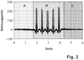
- Fig. 2 Such a time segmentation of a continuous measurement signal of a strain gauge is shown in Fig. 2 shown, three areas A, B, C can be seen. The segmentation is carried out in order to separate a load on the rail switch into an area A before, an area B during and an area C after an overflow of the rail vehicle via the sensor arranged on the rail switch.
- the time segmentation can additionally or alternatively be used for separating overflow signals from a locomotive and wagons and for separate analysis of individual axles.
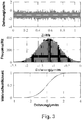
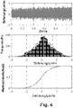
- Fig. 3 and 4th each show recorded and evaluated data of a rail vehicle crossing of a switch heart.
- the uppermost part shows the data recorded by the sensor before a sensor overflow, whereby an expansion is recorded per unit of time.
- a histogram of the acquired signal is shown as a strain-dependent frequency.
- the Kolmogorow-Smirnow test Such an evaluation distinguishes random noise, which is caused by conventional sources, from noise or disturbances, which are caused by an approaching rail vehicle. Noise caused by natural sources usually has a Gaussian distribution. Another statistical distribution points to other causes, for example to a faulty rail vehicle itself, a misshapen wheel of the same, a worn switch heart or other influences.
- Fig. 3 shows a Gaussian distribution
- Fig. 4 shows a different distribution and the data have oscillating components. This allows the conclusion that the in the Fig. 4 recorded and evaluated data represent a deviation from a normal state. In this case, individual flat spots in wheels, which are caused, for example, by braking not conforming to the standards and which lead to non-circular running behavior, can be identified. In the case of rail vehicles which have a Gaussian distribution in the lead, overflow signals can also be used for condition monitoring of the switch.
- Fig. 5 shows recorded data for six rail vehicles running without restrictions when traveling over a rail switch.
- Data from such rail vehicles have a Gaussian distribution in the lead.
- This example is a passenger train traveling at regular intervals via a rail switch instrumented with a sensor.
- locomotives of freight trains can also be compared, since similar rail vehicles also pass a rail switch at regular intervals. It is possible to couple the strain measurement with information about a type of rail vehicle. However, a clear identification of different rail vehicles is also possible without such additional information.
- Fig. 5 The raw data of a time-stretching signal measurement shown can be corrected with respect to an actual speed of the rail vehicle via a standard axis spacing and then made to coincide.
- Fig. 6 This enables a direct comparison of time-expansion curves of the rail vehicles traveling over the rail switch at different times.
- a rail network hereinavy load network, passenger train network or mixed traffic network
- Desired envelopes for each type of rail vehicle are obtained by using static methods, from which a state of a guideway component is subsequently determined and predicted.
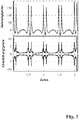
- Fig. 7 shows one from the in 5 and 6 Overflows of the same rail vehicle shown on different days of a week, as well as a deviation of individual measurements from the same. In this way, each new crossing of the same type of rail vehicle can be compared with the previous ones. Long-term monitoring of a form of the envelope curve thus allows direct conclusions to be drawn about a state of a Guideway component. Furthermore, continuous changes are recognized via the envelope curve.
- a continuous change in the envelope curve of a specific rail switch indicates normal wear, for example, while a sudden change in the envelope curve indicates breakouts in the area of a wheel transition. It is expedient to combine the different changes in envelopes with computer simulations of a wheel overflow for a specific switch type and a selected type of rail vehicle in order to improve a correlation between a measured change in the envelopes and a physical change in the route component. Since such computer simulations are very complex, it is expedient to create the results of a computer simulation in advance, for example on an influence of a wear-related change in the geometry of a route on a shape of the envelope curve. During operation, measured envelopes can then be compared on site with calculated curves. In this way, an assessment of a change in state is possible in real time. Subsequently, this also enables a prediction of the development of the condition of a rail switch.
Description
Die Erfindung betrifft ein Verfahren zur insbesondere kontinuierlichen Zustandsüberwachung zumindest einer im Bahnbau verlegten Fahrwegkomponente, insbesondere einer Schienenweiche, mit zumindest einem an der Fahrwegkomponente angeordneten Sensor, wobei vom Sensor bei und zusätzlich vor und/oder nach einer Überrollung der Fahrwegkomponente durch ein Schienenfahrzeug Daten erfasst werden.The invention relates to a method for, in particular, continuous condition monitoring of at least one track component installed in railway construction, in particular a rail switch, with at least one sensor arranged on the track component, data being recorded by the sensor during and additionally before and / or after a rollover of the track component by a rail vehicle .
Weiter betrifft die Erfindung eine Vorrichtung zur insbesondere kontinuierlichen Zustandsüberwachung von zumindest einer im Bahnbau verlegten Fahrwegkomponente, wie einer Schienenweiche, umfassend zumindest einen an der Fahrwegkomponente angeordneten Sensor.The invention further relates to a device for, in particular, continuous condition monitoring of at least one guideway component installed in railway construction, such as a rail switch, comprising at least one sensor arranged on the guideway component.
Aus dem Stand der Technik ist es bekannt, Fahrwegkomponenten im Bahnbau, wie beispielsweise Schienen, zu untersuchen bzw. einen Zustand derselben zu überwachen, um einen Verschleiß solcher Komponenten erkennen zu können. Dies erfolgt beispielsweise durch regelmäßige optische Inspektion. Hierbei überprüft eine Person eine Fahrwegkomponente in vorgegebenen Abständen und entscheidet aufgrund dieser Inspektion über eine Reparatur oder einen Austausch einer solchen Fahrwegkomponente. Diese Methode hat jedoch den Nachteil, dass ein menschliches Auge erst eine starke Abnutzung einer Fahrwegkomponente erkennt. Zudem ist diese Inspektion abhängig von einer Tagesverfassung der inspizierenden Person. Darüber hinaus ist es notwendig, während einer visuellen Inspektion zumindest einen Teilabschnitt einer Bahnstrecke für den Verkehr zu sperren. Trotz einer solchen Sperre ist für die inspizierende Person während der Inspektion aufgrund von Verkehr auf Nebengleisen grundsätzlich noch immer ein bestimmtes Gefahrenpotenzial gegeben.It is known from the prior art to examine track components in railway construction, such as rails, for example, or to monitor a state thereof, in order to be able to detect wear of such components. This is done, for example, by regular optical inspection. Here, a person checks a guideway component at predetermined intervals and, based on this inspection, decides whether to repair or replace such a guideway component. However, this method has the disadvantage that a human eye only recognizes heavy wear of a guideway component. In addition, this inspection depends on the daily condition of the inspecting person. In addition, it is necessary to block at least a section of a railway line from traffic during a visual inspection. Despite such a block, there is still a certain risk potential for the inspecting person during the inspection due to traffic on sidings.
Um diese Nachteile zu überwinden, ist es auch bekannt, Daten einer Fahrwegkomponente bzw. deren Veränderungen automatisiert aufzuzeichnen. Hierzu werden beispielsweise an einem speziell dafür eingesetzten Schienenfahrzeug Sensoren angeordnet, welche beim Befahren auf Schienen wirkende Kräfte messen. Ein Verfahren zur Diagnose einer Schienenweiche mit einem an einem Schienenfahrzeug angeordneten Sensor ist beispielsweise in der
Ferner offenbart beispielsweise die
In der
In der
Es ist mit bekannten Verfahren zum Überwachen einer Fahrwegkomponente nicht möglich, eine kumulierte bzw. aus mehreren Ursachen resultierende Schädigung einer Fahrwegkomponente zu ermitteln. Insbesondere können mehrere Ursachen, welche eine Schädigung bzw. Zustandsänderung einer Fahrwegkomponente bewirken, nicht voneinander entkoppelt erkannt werden.With known methods for monitoring a route component, it is not possible to ascertain a cumulative damage to a route component or resulting from multiple causes. In particular, several causes which cause damage or change in the state of a route component cannot be detected in a decoupled manner.
Hier setzt die Erfindung an. Aufgabe der Erfindung ist es, ein Verfahren der eingangs genannten Art anzugeben, mit welchem ein Zustand einer Fahrwegkomponente, insbesondere einer Schienenweiche, zuverlässig und effektiv sowie automatisiert erkannt werden kann.This is where the invention comes in. The object of the invention is to provide a method of the type mentioned at the outset with which a state of a guideway component, in particular a rail switch, can be reliably and effectively and automatically recognized.
Ein weiteres Ziel ist es, eine Vorrichtung der eingangs genannten Art anzugeben, mit welcher ein Zustand einer Fahrwegkomponente, insbesondere einer Schienenweiche, zuverlässig und effektiv sowie automatisiert erkennbar ist.Another aim is to provide a device of the type mentioned at the outset with which a state of a guideway component, in particular a rail switch, can be reliably and effectively and automatically identified.
Die Erfindung ist durch die Merkmale der unabhängigen Ansprüche definiert.The invention is defined by the features of the independent claims.
Die verfahrensmäßige Aufgabe wird erfindungsgemäß dadurch gelöst, dass bei einem Verfahren der eingangs genannten Art die erfassten Daten zeitlich segmentiert werden, wobei aus den erfassten und segmentierten Daten ein Zustand der Fahrwegkomponente ermittelt wird.The procedural object is achieved according to the invention in that, in a method of the type mentioned at the outset, the acquired data is segmented in time, a state of the route component being determined from the acquired and segmented data.
Ein mit der Erfindung erzielter Vorteil ist insbesondere darin zu sehen, dass durch das Segmentieren der Daten ein Zustand einer Fahrwegkomponente kontinuierlich, automatisiert und in-situ überwacht bzw. ermittelt werden kann. Es können beispielsweise bewegliche Weichen, starre Weichenherzen, Schienen und/oder Schwellen einer Eisenbahnstrecke überwacht werden. Daten werden dabei bevorzugt bei jeder Überrollung der Fahrwegkomponente, insbesondere eines starren Weichenherzens, durch ein Schienenfahrzeug aufgezeichnet und analysiert. Es ist somit eine effiziente Datenauswertung und Dateninterpretation wie beispielsweise eine Störungscharakterisierung und/oder ein Datenvergleich unter Herabsetzung einer Rechenleistung möglich. Insbesondere wird eine Reaktion der Fahrwegkomponente auf einen laufenden Betrieb herangezogen, um Aussagen über einen Zustand derselben zu treffen, beispielsweise eine zeitlich aufgelöste Entwicklung einer Dehnung an einer bestimmten Position. In einem ersten Schritt wird für alle Schienenfahrzeuge an einem Messpunkt eine Belastung der entsprechenden Fahrwegkomponente vor, während und/oder nach einer Überrollung bzw. Überfahrt eines Schienenfahrzeuges gemessen bzw. aufgezeichnet. Die aufgezeichneten bzw. erfassten Daten werden segmentiert bzw. eine Belastung der Fahrwegkomponente in Abhängigkeit einer Zeit ausgewertet. Dabei werden die Daten in drei Teile aufgeteilt: eine Belastung der Fahrwegkomponente vor einer Überfahrt, bei einer Überfahrt sowie nach einer Überfahrt des Schienenfahrzeuges über die Fahrwegkomponente. Darüber hinaus werden optional die Werte des ersten Teils und des dritten Teils miteinander verglichen, also eine Belastung der Fahrwegkomponente unmittelbar vor und nach einer Überfahrt eines Schienenfahrzeuges. Dadurch kann eine Belastungsart an der Fahrwegkomponente charakterisiert werden. Besonders bevorzugt wird ein Zustand einer Fahrwegkomponente von einem einzigen Sensor überwacht, insbesondere von einem Dehnungssensor, welcher z. B. als Dehnmessstreifen oder optische Dehnmesseinrichtung ausgebildet sein kann.An advantage achieved with the invention can be seen in particular in that the state of a guideway component can be monitored or determined continuously, automatically and in-situ by segmenting the data. For example, movable switches, rigid switch hearts, rails and / or sleepers of a railway line can be monitored. Data is preferably recorded and analyzed each time a rail vehicle rolls over the guideway component, in particular a rigid switch heart. Efficient data evaluation and data interpretation such as, for example, a fault characterization and / or a data comparison while reducing computing power is thus possible. In particular, a reaction of the guideway component to an ongoing operation is used to make statements about a state of the same, for example a temporally resolved development of an expansion at a specific position. In a first step, a load of the corresponding guideway component is measured or recorded for all rail vehicles at a measuring point before, during and / or after a rail vehicle is overrun or passed over. The recorded or recorded data are segmented or a load on the guideway component is evaluated as a function of a time. The data is divided into three parts: a load on the guideway component before a crossing, during a crossing and after a crossing of the rail vehicle via the guideway component. In addition, the values of the first part and the third part are optionally compared with one another, that is to say a load on the guideway component immediately before and after a rail vehicle is crossed. In this way, a type of load on the guideway component can be characterized. A state of a guideway component is particularly preferred monitored by a single sensor, in particular by a strain sensor, which, for. B. can be designed as a strain gauge or optical strain gauge.
Darüber hinaus wird mit einem erfindungsgemäßen Verfahren nicht nur ein Zustand einer Fahrwegkomponente wie einer Schienenweiche ermittelt, sondern optional bzw. fallweise auch ein Zustand eines Rades eines Schienenfahrzeuges. Es werden beispielsweise hohl oder unrund gelaufene Räder erkannt. Dies ist insbesondere bei einer Zustandsüberwachung einer Schienenweiche zweckmäßig, da sowohl hohl als auch unrund gelaufene Räder einen Zustand derselben deutlich verschlechtern können. Durch einzelne hohl gelaufene Räder wird eine Zusammenwirkung einer Geometrie von Rad und Weiche verschlechtert, wodurch größere Signale im Bereich eines Radüberganges gemessen und z. B. über Schwellwerte erkannt werden können. Durch unrund gelaufene Räder wird eine Signalstatistik vor und nach einem Radübergang über eine Fahrwegkomponente verschoben. Dies kann durch entsprechende Vergleichsalgorithmen erkannt werden. Ferner ist ein Übergang zwischen einer Schiene und einer Schienenweiche diskontinuierlich ausgebildet, sodass bei einer Überrollung derselben sowohl die Schienenweiche als auch Räder des Schienenfahrzeuges belastet werden. Die Zustände der Schienenweiche und der Räder beeinflussen sich gegenseitig bzw. es tritt ein kumulierter Effekt auf. Die einzelnen Effekte sind in weiterer Folge durch die Segmentierung der erfassten Daten auch entkoppelt voneinander auswertbar. Darüber hinaus können erfasste Daten mithilfe von Computermodellen interpretiert werden, wobei die Computermodelle eine Reaktion der Fahrwegkomponente auf diese überrollende Räder beschreiben. Dadurch können verschiedene Einflussfaktoren separiert werden. Es kann beispielsweise unterschieden werden, ob ein starker Stoß während einer Überrollung der Fahrwegkomponente durch ein hohl gelaufenes Rad oder ein verschlissenes Weichenherz hervorgerufen wird.In addition, with a method according to the invention, not only a state of a guideway component such as a rail switch is determined, but optionally, or occasionally also a state of a wheel of a rail vehicle. For example, hollow or out-of-round wheels are recognized. This is particularly useful when monitoring the condition of a rail switch, since both hollow and non-circular wheels can significantly worsen a condition of the same. Interaction of a geometry of the wheel and switch is deteriorated by individual hollow wheels, whereby larger signals are measured in the area of a wheel transition and z. B. can be recognized via threshold values. Due to out-of-round wheels, signal statistics are shifted before and after a wheel transition over a travel path component. This can be recognized by appropriate comparison algorithms. Furthermore, a transition between a rail and a rail switch is discontinuous, so that when the rail is rolled over, both the rail switch and the wheels of the rail vehicle are loaded. The conditions of the rail switch and the wheels influence each other or there is a cumulative effect. The individual effects can subsequently also be evaluated in a decoupled manner by segmenting the recorded data. In addition, acquired data can be interpreted with the aid of computer models, the computer models describing a reaction of the guideway component to wheels that roll over them. This means that various influencing factors can be separated. For example, a distinction can be made as to whether a strong shock is caused by a hollow wheel or a worn switch heart during a rollover of the guideway component.
Bei der Auswertung der erfassten Daten zur Ermittlung des Zustandes der Fahrwegkomponente werden durch die Segmentierung charakteristische Muster in denselben zur Identifikation einer Schienenfahrzeugart genutzt. Dabei wird grundsätzlich zwischen zwei Schienenfahrzeugarten unterschieden: Schienenfahrzeuge mit einer sich bei jeder Fahrt verändernden Ladung wie Güterzüge und Schienenfahrzeuge mit bei jeder Fahrt im Wesentlichen immer der gleichen Ladung wie Passagierzüge. Bei Schienenfahrzeugen der erstgenannten Art wird die Ladung bzw. ein Gewicht derselben für jede Achse bestimmt und daraus ein Gesamtgewicht des Schienenfahrzeuges berechnet. Es ist somit auch möglich, ein Gewicht eines Waggons eines Güterzuges und somit einen Ladezustand desselben zu erkennen bzw. mit einem theoretischen Ladezustand zu vergleichen.When evaluating the recorded data to determine the state of the guideway component, the segmentation uses characteristic patterns therein to identify a type of rail vehicle. A basic distinction is made between two types of rail vehicle: rail vehicles with a load that changes with each journey, such as freight trains, and rail vehicles with essentially the same load as passenger trains with each journey. At Rail vehicles of the first-mentioned type, the load or a weight thereof is determined for each axle and from this a total weight of the rail vehicle is calculated. It is thus also possible to recognize a weight of a wagon of a freight train and thus its state of charge or to compare it with a theoretical state of charge.
Es ist zweckmäßig, wenn die erfassten und zeitlich segmentierten Daten mit statistischen Methoden und/oder Hüllkurven ausgewertet werden, um einen Zustand einer Fahrwegkomponente vollständig automatisiert charakterisieren und klassifizieren zu können. Durch die Hüllkurven werden automatisch beispielsweise eine Schienenfahrzeugart und eine Geschwindigkeit und/oder Beschleunigung des Schienenfahrzeuges aus den gemessenen Signalen ermittelt. Dies wird insbesondere ohne zusätzliche Geschwindigkeitssensoren, Beschleunigungssensoren und/oder Zuginformationen durchgeführt. Des Weiteren wird mit vorbestimmten Algorithmen beispielsweise ein Zustand eines Weichenherzes einer Schienenweiche vorausgesagt. Darüber hinaus werden Hüllkurven dazu verwendet, einzelne Messungen für eine weitere Analyse zu isolieren. Es werden über die Hüllkurve auch Langzeitabweichungen von derselben erkannt, welche auf fortdauernde Änderungen hinweisen. Eine Voraussetzung für die Auswertung der Daten mit Hüllkurven ist die Segmentierung derselben sowie die automatisierte Ermittlung einer Zuggeschwindigkeit aus Sensordaten.It is expedient if the recorded and time-segmented data are evaluated using statistical methods and / or envelopes in order to be able to characterize and classify a state of a route component in a fully automated manner. The envelope curves automatically determine, for example, a type of rail vehicle and a speed and / or acceleration of the rail vehicle from the measured signals. This is done in particular without additional speed sensors, acceleration sensors and / or train information. Furthermore, a state of a switch heart of a rail switch is predicted using predetermined algorithms. Envelopes are also used to isolate individual measurements for further analysis. Long-term deviations from the envelope are also recognized via the envelope curve, which indicate continuous changes. A prerequisite for evaluating the data with envelopes is segmenting them and automatically determining a train speed from sensor data.
Es ist von Vorteil, wenn die Daten zeitlich aufgetrennt werden. Die erfassten bzw. durch Zugüberfahrten ausgelösten Sensorsignale werden zeitlich nach einzelnen Achsen aufgelöst. Über eine Signalhöhe können dann in weiterer Folge einzelne Achslasten bestimmt werden. Dadurch ist ein Zustand der Fahrwegkomponente nicht nur erkennbar und voraussagbar, sondern auch auf einzelne Ursachen zurückführbar. Darüber hinaus ist es auch möglich, Einflüsse von einem eine Fahrwegkomponente überrollenden Schienenfahrzeug und Einflüsse eines Fahrweges zu entkoppeln. Dies erfolgt bevorzugt automatisiert. Besonders bevorzugt wird eine Signalanalyse in-situ durchgeführt, sodass über aussagekräftige Auswerteergebnisse notwendige Wartungsarbeiten an der Fahrwegkomponente vorhergesagt werden können.It is advantageous if the data is separated in time. The sensor signals recorded or triggered by train crossings are broken down in time according to individual axes. Individual axle loads can then be determined using a signal level. As a result, a state of the guideway component is not only recognizable and predictable, but can also be traced back to individual causes. In addition, it is also possible to decouple influences from a rail vehicle rolling over a guideway component and influences from a guideway. This is preferably done automatically. A signal analysis is particularly preferably carried out in situ , so that necessary maintenance work on the guideway component can be predicted via meaningful evaluation results.
Es kann vorgesehen sein, dass die vom Sensor erfassten und/oder ausgewerteten Daten mit bekannten Daten verglichen werden. Dadurch werden beispielsweise Solldaten mit gemessenen Daten abgeglichen, wodurch eine Abweichung von einem Sollzustand einer Fahrwegkomponente erkannt wird. Es ist somit möglich, eine Qualitätskontrolle einer Fahrwegkomponente durchzuführen. Beispielsweise wird aus den gemessenen und verarbeiteten Daten durch Vergleich mit einer Sollgeometrie einer Weiche eine Güte eines Radüberlaufes direkt nach einem Einbau bewertet, was eine Qualitätskontrolle einer Weichengeometrie und eines lokalen Einbaus ermöglicht. Darüber hinaus wird dadurch insbesondere zufälliges, von natürlichen Quellen verursachtes Rauschen bzw. Störungen von einem sich annähernden Schienenfahrzeug unterschieden. Rauschen, welches von üblichen Quellen verursacht wird, weist in der Regel eine Gaußverteilung auf. Eine andere statistische Verteilung von Daten deutet auf andere Ursachen hin, beispielsweise auf ein mangelhaftes Schienenfahrzeug selbst, ein unförmiges Rad desselben, eine abgesenkte Schienenweiche oder sonstige Abweichungen. In einem ersten Schritt wird folglich eine statistische Verteilung von Daten ermittelt und überprüft, ob die Daten eine Gaußverteilung aufweisen oder statistisch anders verteilt sind. In einem zweiten Schritt wird daraus eine Ursache des Rauschens ermittelt. Ist keine Gaußverteilung vorhanden, wird das Rauschen von einer Unregelmäßigkeit verursacht. Es hat sich als günstig erwiesen, jene Daten, welche aus einer Belastung der Fahrwegkomponente unmittelbar vor einer Überrollung derselben durch ein Schienenfahrzeug erhalten werden, durch einen sogenannten Kolmogorov-Smirnov-Test automatisiert zu überprüfen.It can be provided that the data recorded and / or evaluated by the sensor are compared with known data. As a result, target data are included measured data compared, whereby a deviation from a target state of a route component is detected. It is therefore possible to carry out a quality control of a guideway component. For example, the quality of a wheel overflow is assessed directly after installation from the measured and processed data by comparison with a target geometry of a switch, which enables quality control of a switch geometry and local installation. In addition, this distinguishes in particular random noise or interference caused by natural sources from an approaching rail vehicle. Noise, which is caused by common sources, usually has a Gaussian distribution. Another statistical distribution of data indicates other causes, for example a defective rail vehicle itself, a misshapen wheel of the same, a lowered rail switch or other deviations. In a first step, a statistical distribution of data is consequently determined and it is checked whether the data have a Gaussian distribution or are statistically differently distributed. In a second step, a cause of the noise is determined. If there is no Gaussian distribution, the noise is caused by an irregularity. It has proven to be advantageous to automatically check those data which are obtained from a load on the guideway component immediately before a rail vehicle overruns it by means of a so-called Kolmogorov-Smirnov test.
Vorteilhaft ist es weiter, wenn die erfassten Daten in einer mit dem Sensor verbundenen und unmittelbar an der Fahrwegkomponente angeordneten Signalverarbeitungsanlage zu Informationen über einen Zustand der Fahrwegkomponente verarbeitet werden. Aus den so verarbeiteten Daten werden Einflüsse von einem überrollenden Fahrzeug wie einem Eisenbahnwaggon und einem Fahrweg bzw. einer Fahrwegkomponente, beispielsweise einer Schienenweiche, ausgewertet. Durch die unmittelbare Messung und Auswertung der Daten an der Fahrwegkomponente wird eine große Anzahl von Daten an Ort und Stelle aufgenommen und ausgewertet. Beispielsweise wird eine Dehnung an mindestens einem Punkt der Fahrwegkomponente insbesondere mittels eines Messstreifens oder optischer Verfahren so erfasst, dass durch insbesondere Zugüberfahrten ausgelöste Sensorsignale zeitlich nach einzelnen Achsen aufgelöst werden und eine Signalhöhe durch einzelne Achslasten bestimmt wird. Durch das Auswerten der Daten unmittelbar an der Fahrwegkomponente wird eine Übertragung von großen Datenmengen eingespart. Des Weiteren ist es nicht mehr notwendig, eine Bahnstrecke für eine Aufnahme von Daten zu sperren, wodurch in weiterer Folge auch ununterbrochen bzw. kontinuierlich Daten aufgezeichnet und ausgewertet werden können. Durch die große Anzahl an erfassten und ausgewerteten Daten wird eine Fahrwegkomponente bzw. deren Zustand besonders genau überwacht, wodurch auch kleine Unregelmäßigkeiten erkannt bzw. erfasst werden.It is also advantageous if the acquired data are processed in a signal processing system connected to the sensor and arranged directly on the route component to form information about a state of the route component. From the data processed in this way, influences from a rolling vehicle such as a railway wagon and a track or a track component, for example a rail switch, are evaluated. Due to the direct measurement and evaluation of the data on the guideway component, a large amount of data is recorded and evaluated on the spot. For example, an extension at at least one point of the guideway component is recorded, in particular by means of a measuring strip or optical method, in such a way that sensor signals triggered by train crossings in particular are resolved in time according to individual axes and a signal level is determined by individual axle loads. By evaluating the data directly on the guideway component, a transfer of large amounts of data is saved. Furthermore, it is no longer necessary to record a railway line for Block data, which means that data can be recorded and evaluated continuously or continuously. Due to the large number of recorded and evaluated data, a guideway component or its status is monitored particularly precisely, as a result of which even small irregularities are recognized or recorded.
Zweckmäßig ist es, wenn bei jeder Überfahrt eines Schienenfahrzeuges über die Fahrwegkomponente von dem zumindest einen Sensor Daten erfasst werden. Dadurch wird eine Fahrwegkomponente wie beispielsweise eine Schienenweiche bei jeder Überrollung eines Schienenfahrzeuges kontinuierlich überwacht. Bei jeder Überfahrt eines Schienenfahrzeuges wird ein Sensorsignal ausgelöst. Im Unterschied zu einer punktuellen Überwachung ist es damit möglich, genauere bzw. zeitlich aufgelöste Voraussagen über einen Zustand einer Fahrwegkomponente zu treffen. Darüber hinaus kann vorgesehen sein, dass die Auswerteergebnisse automatisch und kontinuierlich an zentrale Punkte, wie beispielsweise eine lokale Fahrdienstleitung oder eine Zentrale der Infrastrukturgesellschaft übermittelt werden. Durch die Übermittlung von Auswerteergebnissen anstatt der gemessenen Daten wird eine zu übertragende Datenmenge deutlich reduziert.It is expedient if data is recorded by the at least one sensor each time a rail vehicle passes over the guideway component. As a result, a guideway component, such as a rail switch, is continuously monitored each time a rail vehicle is rolled over. A sensor signal is triggered each time a rail vehicle passes. In contrast to selective monitoring, it is thus possible to make more precise or temporally resolved predictions about a state of a route component. In addition, it can be provided that the evaluation results are automatically and continuously transmitted to central points, such as a local driving service or a headquarters of the infrastructure company. By transmitting evaluation results instead of the measured data, a quantity of data to be transmitted is significantly reduced.
Zur Verfolgung der Veränderung von Daten über längere Zeiträume kann es vorgesehen sein, dass analysierte und reduzierte Daten über beispielsweise Funknetzwerke an Zentralrechner übertragen werden. Insbesondere werden dabei Daten von verschiedenen Messpunkten übertragen und zusammengeführt. Durch eine intelligente Datenanalyse, welche durch Computermodelle der Fahrwegkomponente ermöglicht wird, können Änderungen über einen längeren Zeitraum erfasst und analysiert werden. Daraus können in weiterer Folge Handlungserfordernisse abgeleitet werden, wie beispielsweise eine Vorhersage einer nächsten Inspektion oder eine Planung eines Austausches der Fahrwegkomponente aufgrund eines Erreichens kritischer Verschleißzustände. Durch diese systematische Zusammenführung von reduzierten Daten von verschiedenen Messpunkten können Aussagen über einen Zustand ganzer Fahrwerksnetze getroffen werden. Diese Informationen können weiter zur Verbesserung und Optimierung der Wartungs- und/oder Austauschlogistik herangezogen werden.To track the change in data over longer periods of time, it can be provided that analyzed and reduced data are transmitted to central computers via, for example, radio networks. In particular, data from different measuring points are transmitted and merged. Through an intelligent data analysis, which is made possible by computer models of the route component, changes can be recorded and analyzed over a longer period of time. Action requirements can subsequently be derived from this, such as, for example, predicting a next inspection or planning an exchange of the guideway component due to reaching critical wear states. This systematic merging of reduced data from different measuring points enables statements to be made about the condition of entire chassis networks. This information can be used to improve and optimize maintenance and / or replacement logistics.
Es ist von Vorteil, wenn vom Sensor zumindest eine Dehnung pro Zeiteinheit der Fahrwegkomponente gemessen wird. Diese wird insbesondere von einem Dehnmessstreifen erfasst, welcher unmittelbar an der Fahrwegkomponente angeordnet wird. Alternativ kann die Dehnung pro Zeiteinheit auch durch ein optisches Dehnmessverfahren ermittelt werden. Aus einem gemessenen zeitlichen Dehnungssignal wird in weiterer Folge beispielsweise eine Geschwindigkeit und/oder eine Beschleunigung eines die Fahrwegkomponente überrollenden Schienenfahrzeuges ermittelt.It is advantageous if the sensor measures at least one elongation per unit time of the guideway component. This is recorded in particular by a strain gauge, which is arranged directly on the guideway component. Alternatively, the strain per unit of time can also be determined by an optical strain measurement method. From a measured temporal expansion signal, a speed and / or an acceleration of a rail vehicle rolling over the guideway component is subsequently determined, for example.
Das weitere Ziel wird erreicht, wenn eine Vorrichtung der eingangs genannten Art zur Durchführung eines erfindungsgemäßen Verfahrens ausgebildet ist, wobei eine Signalverarbeitungsanlage vorgesehen ist, um vom Sensor erfasste Daten unmittelbar an der Fahrwegkomponente auszuwerten.The further goal is achieved if a device of the type mentioned at the outset is designed to carry out a method according to the invention, a signal processing system being provided in order to evaluate data detected by the sensor directly on the route component.
Ein damit erzielter Vorteil ist insbesondere darin zu sehen, dass durch die direkte Anordnung der Signalverarbeitungsanlage an der Fahrwegkomponente vom Sensor erfasste Daten an Ort und Stelle auswertbar sind. Somit sind erfasste Daten in der Signalverarbeitungsanlage unmittelbar vor Ort zu aussagekräftigen Informationen über einen Zustand einer Fahrwegkomponente wie einer Schienenweiche verarbeitbar. In weiterer Folge ist dadurch ein Zeitpunkt für eine Reparatur bzw. einen Austausch der überwachten Fahrwegkomponente voraussagbar. Insbesondere kann ein Sensor zur Messung bzw. Erfassung einer Dehnung pro Zeiteinheit vorgesehen sein, z. B. ein Dehnungssensor, welcher unmittelbar an der Fahrwegkomponente angeordnet ist. Der Dehnungssensor kann beispielsweise als Dehnmessstreifen oder optische Dehnmesseinrichtung ausgebildet sein. Die Signalverarbeitungsanlage ermittelt aus den vom Sensor erfassten Daten beispielsweise eine Geschwindigkeit und/oder Beschleunigung eines Schienenfahrzeuges, welches über die Fahrwegkomponente mit dem Sensor fährt. Hierzu ist der Sensor mit der Signalverarbeitungsanlage verbunden. Ein Abstand der Achsen des Schienenfahrzeuges ist im Allgemeinen bekannt, da dieser üblicherweise genormt ist. Weiter kann es vorgesehen sein, dass die Signalverarbeitungsanlage aus den verarbeiteten Daten ohne zusätzliche Sensoren eine Schienenfahrzeugart sowie ein Gewicht und eine Geschwindigkeit des Schienenfahrzeuges ermittelt.An advantage achieved in this way can be seen, in particular, in the fact that, due to the direct arrangement of the signal processing system on the guideway component, data recorded by the sensor can be evaluated on the spot. Thus, recorded data can be processed in the signal processing system directly on site to provide meaningful information about a state of a guideway component such as a rail switch. Subsequently, a point in time for a repair or an exchange of the monitored guideway component can be predicted. In particular, a sensor for measuring or detecting an elongation per unit of time can be provided, e.g. B. a strain sensor, which is arranged directly on the guideway component. The strain sensor can be designed, for example, as a strain gauge or optical strain gauge. From the data recorded by the sensor, the signal processing system determines, for example, a speed and / or acceleration of a rail vehicle that travels with the sensor via the guideway component. For this purpose, the sensor is connected to the signal processing system. A distance between the axles of the rail vehicle is generally known since this is usually standardized. It can also be provided that the Signal processing system determines a type of rail vehicle as well as a weight and a speed of the rail vehicle from the processed data without additional sensors.
Grundsätzlich ist es ausreichend, wenn ein einzelner Sensor vorgesehen ist, bevorzugt ein Dehnungssensor. Günstig ist es jedoch, wenn an einer Fahrwegkomponente mehrere Sensoren angeordnet sind, wobei bevorzugt die Sensoren zur Messung unterschiedlicher Daten ausgebildet und mit der Signalverarbeitungsanlage verbunden sind. Die Signalverarbeitungsanlage wertet dann die an diese von jedem Sensor übermittelten Daten aus. Als Sensoren können neben einem Dehnmessstreifen ein Temperatursensor, ein Schallsensor, eine optische Dehnmesseinrichtung und/oder dergleichen vorgesehen sein. Zweckmäßig ist es, wenn die Sensoren unterschiedlicher Art sind, es kann jedoch auch günstig sein, wenn zwei oder mehr gleichartige Sensoren an einer Fahrwegkomponente angeordnet sind.Basically, it is sufficient if a single sensor is provided, preferably a strain sensor. However, it is expedient if a plurality of sensors are arranged on a guideway component, the sensors preferably being designed to measure different data and being connected to the signal processing system. The signal processing system then evaluates the data transmitted to it by each sensor. In addition to a strain gauge, a temperature sensor, a sound sensor, an optical strain gauge and / or the like may be provided. It is expedient if the sensors are of different types, but it can also be advantageous if two or more sensors of the same type are arranged on a guideway component.
Es ist weiter zweckmäßig, wenn an mehreren Fahrwegkomponenten jeweils ein oder mehrere Sensoren sowie jeweils eine Signalverarbeitungsanlage angeordnet sind. Dabei sind beispielsweise an Schienen, an Schienenweichen oder dergleichen jeweils ein oder mehrere Sensoren angeordnet, welche unterschiedliche Daten aufnehmen. Es ist somit ein sogenannter Sensorschwarm vorgesehen, wobei die Sensoren in einem Abstand von 100 m bis 1000 m, bevorzugt von 250 m bis 750 m, insbesondere von etwa 500 m, voneinander angeordnet sind. Allgemein gilt, dass ein Abstand zwischen einzelnen Sensoren von einer Streckenführung abhängig ist. So können beispielsweise in einem im Wesentlichen geraden Streckenbereich Sensoren, welche in einem Abstand von 1000 m oder mehr zueinander angeordnet sind, ausreichend sein. Im Gegensatz dazu ist es zweckmäßig, in einem stark belasteten Streckenbereich mit Kurven und Weichen mehrere Sensoren mit einem geringeren Abstand zueinander anzuordnen. Insbesondere ist es günstig, wenn in äquidistanten Abständen eines Streckenbereiches eines Schienennetzwerkes immer die gleiche Anzahl sowie Art von Sensoren angeordnet sind, sodass die jeweiligen erfassten Daten miteinander und/oder gegebenenfalls mit Standarddaten vergleichbar sind. Besonders zweckmäßig ist es, wenn pro Messpunkt nur ein Sensor angeordnet ist, welcher insbesondere als Dehnungssensor ausgebildet ist.It is also expedient if one or more sensors and a signal processing system are arranged on each of several track components. For example, one or more sensors are arranged on rails, on rail switches or the like, which record different data. A so-called swarm of sensors is thus provided, the sensors being arranged at a distance of 100 m to 1000 m, preferably from 250 m to 750 m, in particular from about 500 m. The general rule is that a distance between individual sensors depends on a route. For example, sensors that are arranged at a distance of 1000 m or more from each other may be sufficient in an essentially straight section. In contrast to this, it is expedient to arrange several sensors with a smaller distance from each other in a heavily loaded route area with curves and switches. In particular, it is advantageous if the same number and type of sensors are always arranged at equidistant intervals of a route area of a rail network, so that the respective recorded data can be compared with one another and / or, where appropriate, with standard data. It is particularly expedient if only one sensor is arranged per measuring point, which is designed in particular as a strain sensor.
Um einen möglichst genauen Zustand von mehreren Fahrwegkomponenten und in weiterer Folge von ganzen Fahrwegnetzen erkennen bzw. voraussagen zu können, ist es von Vorteil, wenn die Signalverarbeitungsanlagen miteinander verbunden sind, um erfasste und/oder ausgewertete Daten auszutauschen. Dadurch ist eine noch genauere Zustandsüberwachung und in weiterer Folge Lebensdauerschätzung von Fahrwegkomponenten möglich. Die an einer Fahrwegkomponente vom Sensor oder den Sensoren erfassten Daten werden von jeder Signalverarbeitungsanlage bevorzugt zuerst ausgewertet und die ausgewerteten Daten werden erst anschließend mit den übrigen Signalverarbeitungsanlagen ausgetauscht, um eine Menge an zu übertragenden Daten so gering wie möglich zu halten. Anschließend können die ausgetauschten Daten miteinander verglichen bzw. abgeglichen werden.In order to be able to recognize or predict the most accurate possible state of several guideway components and subsequently of entire guideway networks, it is advantageous if the signal processing systems are connected to one another in order to exchange recorded and / or evaluated data. This enables even more precise condition monitoring and, subsequently, the lifespan estimation of route components. The data recorded on a route component by the sensor or sensors are preferably first evaluated by each signal processing system and the evaluated data are only subsequently exchanged with the other signal processing systems in order to keep the amount of data to be transmitted as low as possible. The exchanged data can then be compared or compared.
Es ist vorteilhaft, wenn die Signalverarbeitungsanlage eine Einrichtung zur autarken Energieversorgung umfasst. Diese Einreichung ist beispielsweise als Fotovoltaikanlage ausgebildet. Des Weiteren ist es günstig, wenn die bzw. jede Signalverarbeitungsanlage mit lokalen Energiespeichern sowie einer Vorrichtung zur kabellosen Datenübertragung ausgebildet ist.It is advantageous if the signal processing system comprises a device for self-sufficient energy supply. This submission is designed, for example, as a photovoltaic system. Furthermore, it is advantageous if the or each signal processing system is designed with local energy stores and a device for wireless data transmission.
Eine Verwendung einer erfindungsgemäßen Vorrichtung erfolgt mit Vorteil zur Vorhersage von notwendigen Wartungsarbeiten an einer Fahrwegkomponente im Bahnbau.A device according to the invention is advantageously used to predict necessary maintenance work on a guideway component in railway construction.
Weitere Merkmale, Vorteile und Wirkungen ergeben sich aus dem nachfolgend dargestellten Ausführungsbeispiel. In den Zeichnungen, auf welchen dabei Bezug genommen wird, zeigen:
-
Fig. 1 erfasste Daten von unterschiedlichen Schienenfahrzeugen bei einer Fahrt über eine Schienenweiche; -
Fig. 2 eine zeitliche Segmentierung von erfassten Daten; -
Fig. 3 erfasste und ausgewertete Daten eines Schienenfahrzeuges bei einer Fahrt über eine Schienenweiche; -
Fig. 4 erfasste und ausgewertete Daten eines weiteren Schienenfahrzeuges bei einer Fahrt über eine Schienenweiche; -
Fig. 5 zeigt erfasste Daten für sechs Schienenfahrzeuge bei einer Fahrt über eine Schienenweiche; -
Fig. 6 in Deckung gebrachte Daten gemäßFig. 5 ; -
Fig. 7 Hüllkurven und Abweichungen.
-
Fig. 1 recorded data from different rail vehicles when traveling over a rail switch; -
Fig. 2 a temporal segmentation of recorded data; -
Fig. 3 recorded and evaluated data of a rail vehicle when traveling over a rail switch; -
Fig. 4 recorded and evaluated data of another rail vehicle when traveling over a rail switch; -
Fig. 5 shows recorded data for six rail vehicles when traveling over a rail switch; -
Fig. 6 Covered data according toFig. 5 ; -
Fig. 7 Envelopes and deviations.
Bei einem erfindungsgemäßen Verfahren zur Überwachung einer im Bahnbau verlegten Fahrwegkomponente wird zumindest ein Sensor an der Fahrwegkomponente angeordnet. Für die in
Bei der Auswertung der erfassten Daten werden charakteristische Muster in denselben zur Identifikation einer Schienenfahrzeugart genutzt. Bei allen Schienenfahrzeugen wird an einem Messpunkt eine Belastung der entsprechenden Fahrwegkomponente vor, während und nach einer Überfahrt eines Schienenfahrzeuges gemessen, wobei die Daten segmentiert werden. Dies ist aus
Es ist zweckmäßig, aufgenommene Daten zu segmentieren, da es aufgrund der unterschiedlichen Schienenfahrzeugarten bzw. Geschwindigkeiten nicht möglich ist, aufgenommene Daten unmittelbar zu vergleichen. Obwohl die Geschwindigkeiten gleichartiger Schienenfahrzeuge aufgrund einer vorgegebenen Streckengeschwindigkeit nur geringfügig streuen, ist es zweckmäßig, die Geschwindigkeit jedes einzelnen Schienenfahrzeuges über den genormten Achsenabstand direkt aus den Dehnungssignalen zu ermitteln. Eine solche zeitliche Segmentierung eines kontinuierlichen Messsignals eines Dehnmessstreifens ist in
Eine Überwachung der Statistik der Dehnungssignale vor und/oder nach einem eigentlichen Schienenweichenüberlauf ermöglicht es, ohne Einschränkungen laufende Schienenfahrzeuge von Schienenfahrzeugen mit fehlerhaftem Laufverhalten zu unterscheiden. Einem Bahnbetreiber können folglich solche Informationen geliefert werden. Darüber hinaus können ohne Einschränkungen laufende Schienenfahrzeuge für eine Zustandsüberwachung des Fahrwegs herangezogen werden. Ferner ist es möglich, Statistiken der Dehnungssignale vor und nach einem Schienenweichenüberlauf zu vergleichen. Dadurch werden weitere Informationen über einen Zustand der Schienenweiche gewonnen, wie beispielsweise eine durch den Überlauf verursachte bleibende Verformung derselben.Monitoring the statistics of the expansion signals before and / or after an actual rail switch overflow makes it possible to distinguish running rail vehicles from rail vehicles with faulty running behavior without restrictions. Such information can therefore be provided to a railway operator. In addition, running rail vehicles can be used for condition monitoring of the route without restrictions. It is also possible to compare statistics of the expansion signals before and after a rail switch overflow. This provides further information about a condition of the rail switch, such as a permanent deformation caused by the overflow.
In
Aus den auf eine gleiche Zeitachse skalierten Zeit-Dehnungskurven gemäß
Eine kontinuierliche Veränderung der Hüllkurve einer spezifischen Schienenweiche deutet beispielsweise auf normalen Verschleiß hin, während eine sprunghafte Änderung der Hüllkurve auf Ausbrüche im Bereich eines Radüberganges hinweist. Es ist zweckmäßig, die unterschiedlichen Veränderungen von Hüllkurven mit Computersimulationen eines Radüberlaufes für einen spezifischen Weichentyp und einer gewählten Schienenfahrzeugart zu kombinieren, um eine Korrelation zwischen einer gemessenen Veränderung der Hüllkurven und einer physikalischen Veränderung der Fahrwegkomponente zu verbessern. Da solche Computersimulationen sehr aufwendig sind, ist es günstig, Ergebnisse einer Computersimulation zu beispielsweise einem Einfluss einer verschleißbedingten Geometrieveränderung eines Fahrweges auf eine Form der Hüllkurve vorab zu erstellen. Im Betrieb können gemessene Hüllkurven sodann vor Ort mit berechneten Kurven verglichen werden. Auf diese Weise ist eine Bewertung einer Zustandsveränderung in Echtzeit möglich. In weiterer Folge ermöglicht dies auch eine Vorhersage einer Zustandsentwicklung einer Schienenweiche.A continuous change in the envelope curve of a specific rail switch indicates normal wear, for example, while a sudden change in the envelope curve indicates breakouts in the area of a wheel transition. It is expedient to combine the different changes in envelopes with computer simulations of a wheel overflow for a specific switch type and a selected type of rail vehicle in order to improve a correlation between a measured change in the envelopes and a physical change in the route component. Since such computer simulations are very complex, it is expedient to create the results of a computer simulation in advance, for example on an influence of a wear-related change in the geometry of a route on a shape of the envelope curve. During operation, measured envelopes can then be compared on site with calculated curves. In this way, an assessment of a change in state is possible in real time. Subsequently, this also enables a prediction of the development of the condition of a rail switch.
Claims (11)
- A method for the, in particular, continuous condition monitoring of at least one track component laid in railway construction, in particular a swivel plate, with at least one sensor arranged on the track component, wherein data are detected by the sensor when and also before and/or after a railway vehicle rolls over the track component, characterised in that the detected data are temporally segmented, wherein a condition of the track component is determined from the detected and segmented data.
- The method according to claim 1, characterised in that the detected and temporally segmented data are evaluated with statistical methods and/or envelope curves.
- The method according to claim 1 or 2, characterised in that the data are separated temporally.
- The method according to any one of claims 1 to 3, characterised in that the detected data are processed in a signal processing system connected to the sensor and arranged directly on the track component into information relating to a condition of the track component.
- The method according to any one of claims 1 to 4, characterised in that data are detected by the at least one sensor each time a railway vehicle travels over the track component.
- The method according to any one of claims 1 to 5, characterised in that at least one revolution per unit of time of the track component is measured by the sensor.
- A device for the, in particular, continuous condition monitoring of at least one track component laid in railway construction, such as a swivel plate, comprising at least one sensor arranged on the track component, characterised in that the device is designed for performing a method according to any one of claims 1 to 6, wherein a signal processing system is provided in order to evaluate data detected by the sensor directly on the track component.
- The device according to claim 7, characterised in that a plurality of sensors are arranged on a track component, wherein the sensors are preferably designed for the measurement of different data and are connected to the signal processing system.
- The device according to claim 7 or 8, characterised in that in each case one or more sensors and in each case a signal processing system are arranged on a plurality of track components.
- The device according to claim 9, characterised in that the signal processing systems are connected to one another in order to exchange detected and/or evaluated data.
- The device according to any one of claims 7 to 10, characterised in that the signal processing system comprises a device for a self-sufficient energy supply.
Applications Claiming Priority (2)
| Application Number | Priority Date | Filing Date | Title |
|---|---|---|---|
| ATA50458/2016A AT518759A1 (en) | 2016-05-17 | 2016-05-17 | Method and device for monitoring at least one infrastructure component laid in railway construction |
| PCT/AT2017/060129 WO2017197423A1 (en) | 2016-05-17 | 2017-05-16 | Method and device for monitoring at least one travel path component laid in rail construction |
Publications (2)
| Publication Number | Publication Date |
|---|---|
| EP3458331A1 EP3458331A1 (en) | 2019-03-27 |
| EP3458331B1 true EP3458331B1 (en) | 2020-07-15 |
Family
ID=58744918
Family Applications (1)
| Application Number | Title | Priority Date | Filing Date |
|---|---|---|---|
| EP17724725.1A Active EP3458331B1 (en) | 2016-05-17 | 2017-05-16 | Method and device for monitoring at least one travel path component laid in rail construction |
Country Status (4)
| Country | Link |
|---|---|
| EP (1) | EP3458331B1 (en) |
| AT (1) | AT518759A1 (en) |
| ES (1) | ES2823163T3 (en) |
| WO (1) | WO2017197423A1 (en) |
Families Citing this family (3)
| Publication number | Priority date | Publication date | Assignee | Title |
|---|---|---|---|---|
| US11260888B2 (en) * | 2018-11-16 | 2022-03-01 | Alstom Transport Technologies | Method and system for health assessment of a track circuit and/or of a track section |
| DE102019211406A1 (en) * | 2019-07-31 | 2021-02-04 | Siemens Mobility GmbH | Method for recognizing faulty measurement events and computer program product |
| EP4342764A1 (en) * | 2022-09-20 | 2024-03-27 | voestalpine Signaling Austria GmbH | Method for monitoring a rail switch and switch drive |
Family Cites Families (5)
| Publication number | Priority date | Publication date | Assignee | Title |
|---|---|---|---|---|
| DE4207516A1 (en) * | 1992-03-10 | 1993-09-16 | Gerd R Dipl Ing Wetzler | METHOD FOR GENERATING LOAD-RELATED SWITCHING SIGNALS ON RAILWAY RAILWAYS |
| DE102007034504A1 (en) * | 2007-07-24 | 2009-02-05 | Rögener, Baldur | Method and monitoring system for monitoring rail tracks |
| DE202010009904U1 (en) * | 2010-06-24 | 2011-10-25 | Baldur Rögener | Metrological arrangement for determining the track position and / or changing the track geometry (deformation) |
| DE102011084160A1 (en) * | 2011-10-07 | 2013-04-11 | Siemens Aktiengesellschaft | Method and device for rail break detection |
| DE102014216726A1 (en) * | 2014-08-22 | 2016-02-25 | Siemens Aktiengesellschaft | Method for increasing the availability of a wheel recognition device and wheel recognition device |
-
2016
- 2016-05-17 AT ATA50458/2016A patent/AT518759A1/en unknown
-
2017
- 2017-05-16 ES ES17724725T patent/ES2823163T3/en active Active
- 2017-05-16 WO PCT/AT2017/060129 patent/WO2017197423A1/en unknown
- 2017-05-16 EP EP17724725.1A patent/EP3458331B1/en active Active
Non-Patent Citations (1)
| Title |
|---|
| None * |
Also Published As
| Publication number | Publication date |
|---|---|
| ES2823163T3 (en) | 2021-05-06 |
| WO2017197423A1 (en) | 2017-11-23 |
| AT518759A1 (en) | 2017-12-15 |
| EP3458331A1 (en) | 2019-03-27 |
Similar Documents
| Publication | Publication Date | Title |
|---|---|---|
| EP1791748B1 (en) | Diagnosis and state monitoring of junctions, crossings or crossroads and rail joints by means of a rail vehicle | |
| EP2212180B1 (en) | Determining the remaining service life of a vehicle component | |
| EP2359104B1 (en) | System for analysis of vehicle condition in rail vehicles | |
| EP3665048B1 (en) | Method and apparatus for determining changes in the longitudinal dynamic behaviour of a rail vehicle | |
| EP3458331B1 (en) | Method and device for monitoring at least one travel path component laid in rail construction | |
| WO2018041569A1 (en) | Device and method for determining the state of railways | |
| WO2016058727A1 (en) | State diagnosis of rail vehicle wheels | |
| EP2464556B1 (en) | Method and electronic device to monitor the status of components of railway vehicles | |
| EP3374246B1 (en) | Method and device for comparison-controlled detection of derailing | |
| DE19837476A1 (en) | Preventive surveillance and monitoring procedure for railway rolling stock driving characteristics | |
| DE19836081A1 (en) | Failure detection method for rail vehicle component | |
| EP3053804A2 (en) | Method and device for optimizing rail superstructure maintenance by single error classification | |
| DE102020121485B3 (en) | Procedure for the determination and assessment of faults in the vehicle track system within regular railway operations | |
| DE10020519B4 (en) | Method for monitoring the driving properties of a rail vehicle | |
| DE10062602B4 (en) | Method and device for monitoring the behavior of rail vehicles and for diagnosing components of rail vehicles | |
| EP2956348B1 (en) | Monitoring of coupling elements of a vehicle | |
| EP3584199A1 (en) | Method and system for the detection of abrasive wear during operation of a conveying system | |
| EP1165355B1 (en) | Method and device for monitoring a vehicle | |
| DE10020520B4 (en) | Method and device for monitoring the driving properties of a rail vehicle | |
| DE102009015011A1 (en) | Method for monitoring the running stability of rail vehicles | |
| DE102008008578B3 (en) | Method for determining dynamic wheel strength during passage of railway vehicle on core of guide, crossing or crossing guide of rail traffic way, involves measuring concentrated loads on all strength-deriving places with passage of train | |
| WO2018104040A1 (en) | Method and device for diagnosing railway switches under load | |
| DE102021119967A1 (en) | METHOD AND SYSTEM FOR NON-CONTACT, NON-DESTRUCTIVE REAL-TIME COMPONENT MONITORING | |
| EP2718167B1 (en) | Method and controlling device for determining the length of at least one track section | |
| EP3823876A1 (en) | Method and arrangement for identifying a rail vehicle wheel |
Legal Events
| Date | Code | Title | Description |
|---|---|---|---|
| STAA | Information on the status of an ep patent application or granted ep patent |
Free format text: STATUS: UNKNOWN |
|
| STAA | Information on the status of an ep patent application or granted ep patent |
Free format text: STATUS: THE INTERNATIONAL PUBLICATION HAS BEEN MADE |
|
| PUAI | Public reference made under article 153(3) epc to a published international application that has entered the european phase |
Free format text: ORIGINAL CODE: 0009012 |
|
| STAA | Information on the status of an ep patent application or granted ep patent |
Free format text: STATUS: REQUEST FOR EXAMINATION WAS MADE |
|
| 17P | Request for examination filed |
Effective date: 20181214 |
|
| AK | Designated contracting states |
Kind code of ref document: A1 Designated state(s): AL AT BE BG CH CY CZ DE DK EE ES FI FR GB GR HR HU IE IS IT LI LT LU LV MC MK MT NL NO PL PT RO RS SE SI SK SM TR |
|
| AX | Request for extension of the european patent |
Extension state: BA ME |
|
| DAV | Request for validation of the european patent (deleted) | ||
| DAX | Request for extension of the european patent (deleted) | ||
| STAA | Information on the status of an ep patent application or granted ep patent |
Free format text: STATUS: EXAMINATION IS IN PROGRESS |
|
| 17Q | First examination report despatched |
Effective date: 20191209 |
|
| GRAP | Despatch of communication of intention to grant a patent |
Free format text: ORIGINAL CODE: EPIDOSNIGR1 |
|
| STAA | Information on the status of an ep patent application or granted ep patent |
Free format text: STATUS: GRANT OF PATENT IS INTENDED |
|
| INTG | Intention to grant announced |
Effective date: 20200506 |
|
| GRAS | Grant fee paid |
Free format text: ORIGINAL CODE: EPIDOSNIGR3 |
|
| GRAA | (expected) grant |
Free format text: ORIGINAL CODE: 0009210 |
|
| STAA | Information on the status of an ep patent application or granted ep patent |
Free format text: STATUS: THE PATENT HAS BEEN GRANTED |
|
| AK | Designated contracting states |
Kind code of ref document: B1 Designated state(s): AL AT BE BG CH CY CZ DE DK EE ES FI FR GB GR HR HU IE IS IT LI LT LU LV MC MK MT NL NO PL PT RO RS SE SI SK SM TR |
|
| REG | Reference to a national code |
Ref country code: CH Ref legal event code: EP Ref country code: GB Ref legal event code: FG4D Free format text: NOT ENGLISH |
|
| REG | Reference to a national code |
Ref country code: DE Ref legal event code: R096 Ref document number: 502017006220 Country of ref document: DE |
|
| REG | Reference to a national code |
Ref country code: IE Ref legal event code: FG4D Free format text: LANGUAGE OF EP DOCUMENT: GERMAN |
|
| REG | Reference to a national code |
Ref country code: AT Ref legal event code: REF Ref document number: 1290720 Country of ref document: AT Kind code of ref document: T Effective date: 20200815 |
|
| REG | Reference to a national code |
Ref country code: CH Ref legal event code: NV Representative=s name: INDUSTRIAL PROPERTY SERVICES GMBH, CH |
|
| REG | Reference to a national code |
Ref country code: NL Ref legal event code: FP |
|
| REG | Reference to a national code |
Ref country code: SE Ref legal event code: TRGR |
|
| REG | Reference to a national code |
Ref country code: LT Ref legal event code: MG4D |
|
| PG25 | Lapsed in a contracting state [announced via postgrant information from national office to epo] |
Ref country code: FI Free format text: LAPSE BECAUSE OF FAILURE TO SUBMIT A TRANSLATION OF THE DESCRIPTION OR TO PAY THE FEE WITHIN THE PRESCRIBED TIME-LIMIT Effective date: 20200715 Ref country code: LT Free format text: LAPSE BECAUSE OF FAILURE TO SUBMIT A TRANSLATION OF THE DESCRIPTION OR TO PAY THE FEE WITHIN THE PRESCRIBED TIME-LIMIT Effective date: 20200715 Ref country code: PT Free format text: LAPSE BECAUSE OF FAILURE TO SUBMIT A TRANSLATION OF THE DESCRIPTION OR TO PAY THE FEE WITHIN THE PRESCRIBED TIME-LIMIT Effective date: 20201116 Ref country code: BG Free format text: LAPSE BECAUSE OF FAILURE TO SUBMIT A TRANSLATION OF THE DESCRIPTION OR TO PAY THE FEE WITHIN THE PRESCRIBED TIME-LIMIT Effective date: 20201015 Ref country code: NO Free format text: LAPSE BECAUSE OF FAILURE TO SUBMIT A TRANSLATION OF THE DESCRIPTION OR TO PAY THE FEE WITHIN THE PRESCRIBED TIME-LIMIT Effective date: 20201015 Ref country code: GR Free format text: LAPSE BECAUSE OF FAILURE TO SUBMIT A TRANSLATION OF THE DESCRIPTION OR TO PAY THE FEE WITHIN THE PRESCRIBED TIME-LIMIT Effective date: 20201016 Ref country code: HR Free format text: LAPSE BECAUSE OF FAILURE TO SUBMIT A TRANSLATION OF THE DESCRIPTION OR TO PAY THE FEE WITHIN THE PRESCRIBED TIME-LIMIT Effective date: 20200715 |
|
| PG25 | Lapsed in a contracting state [announced via postgrant information from national office to epo] |
Ref country code: RS Free format text: LAPSE BECAUSE OF FAILURE TO SUBMIT A TRANSLATION OF THE DESCRIPTION OR TO PAY THE FEE WITHIN THE PRESCRIBED TIME-LIMIT Effective date: 20200715 Ref country code: PL Free format text: LAPSE BECAUSE OF FAILURE TO SUBMIT A TRANSLATION OF THE DESCRIPTION OR TO PAY THE FEE WITHIN THE PRESCRIBED TIME-LIMIT Effective date: 20200715 Ref country code: LV Free format text: LAPSE BECAUSE OF FAILURE TO SUBMIT A TRANSLATION OF THE DESCRIPTION OR TO PAY THE FEE WITHIN THE PRESCRIBED TIME-LIMIT Effective date: 20200715 Ref country code: IS Free format text: LAPSE BECAUSE OF FAILURE TO SUBMIT A TRANSLATION OF THE DESCRIPTION OR TO PAY THE FEE WITHIN THE PRESCRIBED TIME-LIMIT Effective date: 20201115 |
|
| REG | Reference to a national code |
Ref country code: DE Ref legal event code: R097 Ref document number: 502017006220 Country of ref document: DE |
|
| PG25 | Lapsed in a contracting state [announced via postgrant information from national office to epo] |
Ref country code: DK Free format text: LAPSE BECAUSE OF FAILURE TO SUBMIT A TRANSLATION OF THE DESCRIPTION OR TO PAY THE FEE WITHIN THE PRESCRIBED TIME-LIMIT Effective date: 20200715 Ref country code: CZ Free format text: LAPSE BECAUSE OF FAILURE TO SUBMIT A TRANSLATION OF THE DESCRIPTION OR TO PAY THE FEE WITHIN THE PRESCRIBED TIME-LIMIT Effective date: 20200715 Ref country code: RO Free format text: LAPSE BECAUSE OF FAILURE TO SUBMIT A TRANSLATION OF THE DESCRIPTION OR TO PAY THE FEE WITHIN THE PRESCRIBED TIME-LIMIT Effective date: 20200715 Ref country code: EE Free format text: LAPSE BECAUSE OF FAILURE TO SUBMIT A TRANSLATION OF THE DESCRIPTION OR TO PAY THE FEE WITHIN THE PRESCRIBED TIME-LIMIT Effective date: 20200715 Ref country code: SM Free format text: LAPSE BECAUSE OF FAILURE TO SUBMIT A TRANSLATION OF THE DESCRIPTION OR TO PAY THE FEE WITHIN THE PRESCRIBED TIME-LIMIT Effective date: 20200715 |
|
| REG | Reference to a national code |
Ref country code: ES Ref legal event code: FG2A Ref document number: 2823163 Country of ref document: ES Kind code of ref document: T3 Effective date: 20210506 |
|
| PLBE | No opposition filed within time limit |
Free format text: ORIGINAL CODE: 0009261 |
|
| STAA | Information on the status of an ep patent application or granted ep patent |
Free format text: STATUS: NO OPPOSITION FILED WITHIN TIME LIMIT |
|
| PG25 | Lapsed in a contracting state [announced via postgrant information from national office to epo] |
Ref country code: AL Free format text: LAPSE BECAUSE OF FAILURE TO SUBMIT A TRANSLATION OF THE DESCRIPTION OR TO PAY THE FEE WITHIN THE PRESCRIBED TIME-LIMIT Effective date: 20200715 |
|
| 26N | No opposition filed |
Effective date: 20210416 |
|
| PG25 | Lapsed in a contracting state [announced via postgrant information from national office to epo] |
Ref country code: SK Free format text: LAPSE BECAUSE OF FAILURE TO SUBMIT A TRANSLATION OF THE DESCRIPTION OR TO PAY THE FEE WITHIN THE PRESCRIBED TIME-LIMIT Effective date: 20200715 |
|
| PG25 | Lapsed in a contracting state [announced via postgrant information from national office to epo] |
Ref country code: SI Free format text: LAPSE BECAUSE OF FAILURE TO SUBMIT A TRANSLATION OF THE DESCRIPTION OR TO PAY THE FEE WITHIN THE PRESCRIBED TIME-LIMIT Effective date: 20200715 |
|
| PG25 | Lapsed in a contracting state [announced via postgrant information from national office to epo] |
Ref country code: LU Free format text: LAPSE BECAUSE OF NON-PAYMENT OF DUE FEES Effective date: 20210516 Ref country code: MC Free format text: LAPSE BECAUSE OF FAILURE TO SUBMIT A TRANSLATION OF THE DESCRIPTION OR TO PAY THE FEE WITHIN THE PRESCRIBED TIME-LIMIT Effective date: 20200715 |
|
| PG25 | Lapsed in a contracting state [announced via postgrant information from national office to epo] |
Ref country code: IE Free format text: LAPSE BECAUSE OF NON-PAYMENT OF DUE FEES Effective date: 20210516 |
|
| PG25 | Lapsed in a contracting state [announced via postgrant information from national office to epo] |
Ref country code: CY Free format text: LAPSE BECAUSE OF FAILURE TO SUBMIT A TRANSLATION OF THE DESCRIPTION OR TO PAY THE FEE WITHIN THE PRESCRIBED TIME-LIMIT Effective date: 20200715 |
|
| P01 | Opt-out of the competence of the unified patent court (upc) registered |
Effective date: 20230527 |
|
| PG25 | Lapsed in a contracting state [announced via postgrant information from national office to epo] |
Ref country code: HU Free format text: LAPSE BECAUSE OF FAILURE TO SUBMIT A TRANSLATION OF THE DESCRIPTION OR TO PAY THE FEE WITHIN THE PRESCRIBED TIME-LIMIT; INVALID AB INITIO Effective date: 20170516 |
|
| PGFP | Annual fee paid to national office [announced via postgrant information from national office to epo] |
Ref country code: NL Payment date: 20230519 Year of fee payment: 7 Ref country code: IT Payment date: 20230526 Year of fee payment: 7 Ref country code: FR Payment date: 20230526 Year of fee payment: 7 Ref country code: DE Payment date: 20230519 Year of fee payment: 7 Ref country code: CH Payment date: 20230602 Year of fee payment: 7 |
|
| PGFP | Annual fee paid to national office [announced via postgrant information from national office to epo] |
Ref country code: SE Payment date: 20230519 Year of fee payment: 7 Ref country code: AT Payment date: 20230412 Year of fee payment: 7 |
|
| PGFP | Annual fee paid to national office [announced via postgrant information from national office to epo] |
Ref country code: BE Payment date: 20230519 Year of fee payment: 7 |
|
| PGFP | Annual fee paid to national office [announced via postgrant information from national office to epo] |
Ref country code: GB Payment date: 20230524 Year of fee payment: 7 Ref country code: ES Payment date: 20230727 Year of fee payment: 7 |