EP3458236B1 - Artificial hand having finger units provided with a photo coupler contact force sensor - Google Patents
Artificial hand having finger units provided with a photo coupler contact force sensor Download PDFInfo
- Publication number
- EP3458236B1 EP3458236B1 EP16736641.8A EP16736641A EP3458236B1 EP 3458236 B1 EP3458236 B1 EP 3458236B1 EP 16736641 A EP16736641 A EP 16736641A EP 3458236 B1 EP3458236 B1 EP 3458236B1
- Authority
- EP
- European Patent Office
- Prior art keywords
- distal
- photo
- phalange segment
- inter
- segment
- Prior art date
- Legal status (The legal status is an assumption and is not a legal conclusion. Google has not performed a legal analysis and makes no representation as to the accuracy of the status listed.)
- Active
Links
Images




Classifications
-
- B—PERFORMING OPERATIONS; TRANSPORTING
- B25—HAND TOOLS; PORTABLE POWER-DRIVEN TOOLS; MANIPULATORS
- B25J—MANIPULATORS; CHAMBERS PROVIDED WITH MANIPULATION DEVICES
- B25J15/00—Gripping heads and other end effectors
- B25J15/0009—Gripping heads and other end effectors comprising multi-articulated fingers, e.g. resembling a human hand
-
- B—PERFORMING OPERATIONS; TRANSPORTING
- B25—HAND TOOLS; PORTABLE POWER-DRIVEN TOOLS; MANIPULATORS
- B25J—MANIPULATORS; CHAMBERS PROVIDED WITH MANIPULATION DEVICES
- B25J17/00—Joints
- B25J17/02—Wrist joints
- B25J17/0208—Compliance devices
-
- B—PERFORMING OPERATIONS; TRANSPORTING
- B25—HAND TOOLS; PORTABLE POWER-DRIVEN TOOLS; MANIPULATORS
- B25J—MANIPULATORS; CHAMBERS PROVIDED WITH MANIPULATION DEVICES
- B25J19/00—Accessories fitted to manipulators, e.g. for monitoring, for viewing; Safety devices combined with or specially adapted for use in connection with manipulators
- B25J19/02—Sensing devices
- B25J19/021—Optical sensing devices
-
- B—PERFORMING OPERATIONS; TRANSPORTING
- B25—HAND TOOLS; PORTABLE POWER-DRIVEN TOOLS; MANIPULATORS
- B25J—MANIPULATORS; CHAMBERS PROVIDED WITH MANIPULATION DEVICES
- B25J9/00—Program-controlled manipulators
- B25J9/0009—Constructional details, e.g. manipulator supports, bases
- B25J9/0015—Flexure members, i.e. parts of manipulators having a narrowed section allowing articulation by flexion
-
- B—PERFORMING OPERATIONS; TRANSPORTING
- B25—HAND TOOLS; PORTABLE POWER-DRIVEN TOOLS; MANIPULATORS
- B25J—MANIPULATORS; CHAMBERS PROVIDED WITH MANIPULATION DEVICES
- B25J13/00—Controls for manipulators
- B25J13/08—Controls for manipulators by means of sensing devices, e.g. viewing or touching devices
- B25J13/085—Force or torque sensors
Definitions
- the present invention generally concerns an artificial hand having finger units provided with a photo coupler contact force sensor to measure relative displacement around an articulation between associated parts.
- Dexterity is one of the important features to have for a robotic hand. Dexterity gives a robotic hand to have a capability of changing the position and orientation of the manipulated object from a given reference configuration to a different one, arbitrarily chosen within the hand workspace. That briefly tells a robotic hand should be a mimic of a real human hand as good as it can be to operate well. Like other technologies, the technology of robotic hands has globally evolved as time passed by.
- An artificial or prosthetic hand continuously interacts with the environment either grasping an object, carrying objects, reaching places that human beings cannot, so on and so forth.
- continuous monitoring of the feedback force is critical to perform delegate and sophisticated tasks like holding an egg, handshaking with a person or holding a paper cup with a volatile level of liquid. In all cases, it is required to apply a certain amount of force so that the egg will not collapse, hand will not be squeezed or paper cup will not fall and will have a condition so that liquid is drinkable.
- a feedback or contact force sensor is required that detects the force by using different phenomenon e.g. piezoresistivity, conductive or inductive, piezoelectric and strain gauges.
- a feedback or contact force is an essential parameter to monitor during the gripping of an object that allows the robotic or prosthetic hand to further increase or decrease the torque of the motor.
- force sensors are usually placed at the anterior side of the fingertip, that results in narrowing the detection angle/area of the force and hence required the specific portion of the tip to be in contact with the object to detect the contact or reaction force.
- EP0523031 disclosing a force sensor consisting of a hollow elastomer cushion in which there is disposed at least one device for optical detection of displacement comprising an infrared LED and a phototransistor which detects the displacement of a surface placed in front of it by measuring the intensity reflected from the surface.
- This force sensor is disposed directly on the finger of the robot, which allows direct and accurate information on the stress tensor relating to the stresses exerted on the finger of the robot to be obtained.
- Primary object of the present invention is to provide an improved contact force sensor comprising at least one photo coupler and at least one photo interrupter to sense a distal phalange via a Distal Inter-Phalangeal (DIP) joint just like human fingers.
- DIP Distal Inter-Phalangeal
- the present invention provides a monitoring system to continuously measure and control the relative movement of phalangeal segments in an artificial hand that can be a robotic/prosthetic hand as defined in the characterized portion of Claim 1.
- the present invention discloses an artificial hand (30) having a distal phalange segment (11), an intermediate phalange segment (12), a flexural distal inter-phalangeal joint (DIP joint) (13) and a proximal inter-phalangeal joint (14) designed in a way that they simulate functioning of a human hand fingers.
- the distal phalange segment (11) is connected to said intermediate phalange segment (12) through said flexural distal inter-phalangeal joint (13).
- the sensing elements that will be explained hereinafter detect the deflection of said semi-rigid flexural distal inter-phalangeal joint (13) caused by the force exerted on the outermost tip of the distal phalange segment (11).
- the distal phalange segment (11) of the invention which constitutes the outer tip of the artificial hand (30), comprises a photo interrupter housing (17) and a photo interrupter mounting slot (18).
- the photo interrupter housing (17) is occupied by the photo interrupter (19) placed therein and it is designed as a generally linear channel to partly enclose said photo interrupter (19).
- the photo interrupter housing's (17) photo interrupter mounting slot (18) is configured in the manner that the photo interrupter (19) is removably installed to be movable in a photo coupler channel (25).
- the intermediate phalange segment (12) of the invention is connected to the distal phalange segment (11) through said flexural distal inter-phalangeal joint (13) and comprises a photo coupler housing (15) and a photo coupler mounting slot (16).
- the photo coupler housing (15) contains a photo coupler (20) to be fixedly placed therein.
- the photo coupler housing (15) acts as a channel maintaining said photo coupler (20).
- the photo coupler housing (15) further has photo coupler mounting slots (16) which serve to the purpose of fixating said photo coupler (20) within said photo coupler housing (15).
- the photo interrupter (19) and the photo coupler (20) together form the contact force sensor (10) of the present invention.
- the artificial hand (30) of the invention is therefore composed of the above-identified individual elements interacting with each other to create the reciprocally induced set of actions.
- the photo coupler housing (15) is formed as a cavity on the intermediate phalange segment (12), preserving the photo coupler (20) while the photo interrupter housing (17) is created on the distal phalange segment (11) and in between the photo coupler (20) and photo interrupter (19) lies the semi rigid flexural distal inter-phalangeal joint (13) that bends with a certain rate "k” causing the photo-interrupter to deflect " ⁇ " when a force "F” is exerted on the tip of the finger. So the net force can be calculated using Hook's law.
- the force on the tip of the contact force sensor (10) causes the flexural distal inter-phalangeal joint (13) to bend in the direction of the force; therefore, resulting the photo interrupter (19) to move into said photo coupler channel (25), thereby blocking the light received from a light source (23) to reach the window of a light sensing unit (24), decreasing the output signal of the photo coupler (20).
- the light source (23) can typically be an LED while said light sensing unit (24) is a photo-transistor.
- the photo interrupter (19) comprises a photo interrupter mounting channel (21) and a beam blocker (22).
- the photo interrupter mounting channel (21) typically allows fixation of the photo interrupter (19) into said photo interrupter housing (17) through any appropriate connection means such as screws.
- the beam blocker (22) is a longitudinal extension with a sufficiently thin transversal dimension to fit the photo coupler channel (25). It basically provides that, depending on its positionment on its longitudinal direction, some amount of the light is blocked from reaching the light sensing unit (24) when said beam blocker (22), movable in accordance with the flexibly supported rotational movement of the distal phalange segment (11), is introduced into said photo coupler channel (25).
- the photo interrupter mounting channel (21) allows to set the initial position of the photo interrupter (19) and thereby the calibrated amount of light reaching the light sensing unit (24) in no load conditions.
- the light source (23) and the light sensing unit (24) are typically facing each other along the same direction.
- the photo interrupter (19) is adapted to be aligned for insertion into the photo coupler channel (25) of the photo coupler (20) in order to be displaced therein for effecting blockage of the light emitted by the light source (23).
- the beam blocker (22) being movable relative to the photo coupler channel (25), a substantially limited movement thereof will cause the blockage of the light.
- the distance “d” as shown by the dashed lines in Fig. 5 is representative of the amount of the tip portion's displacement as the maximum amount of blockage of the LED light from 0% to 100%. Therefore, an electronic control unit is able to calculate the exact amount of blockage in accordance with the final position of the tip portion.
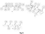
- an additional pair of an inner distal phalange segment (27) and an inner intermediate phalange segment (28) can be attached to each other via a flexural linear inter-phalangeal joint (29), this inner pair of cooperating elements being connected with the outer pair of said distal phalange segment (11) and said intermediate phalange segment (12) through the proximal inter-phalangeal joint (14).
- the outer pair of finger segments in the robotic/artificial hand (30) is connected with an additional inner pair to provide a four-segment artificial hand (30) finger.
- Both pair of finger segments form a longitudinal artificial hand (30) finger attached to a finger root structure (26) from which, a plurality of separate fingers typically extend.
- a certain amount of rotational movement of the distal phalange segment (11) around said flexural distal inter-phalangeal joint (13) can cause linear displacement of an inner photo-interrupter (32) disposed between said inner distal phalange segment (27) and said inner intermediate phalange segment (28).
- the pair of distal phalange segment-intermediate phalange segment (11-12) is connected to the pair of inner distal phalange segment-inner intermediate phalange segment (27-28) through the rotary proximal inter-phalangeal joint (14) and the latter will prevent transmission of any rotational movement to the inner pair of inner distal phalange segment-inner intermediate phalange segment (27-28).
- the flexure means namely the flexural linear inter-phalangeal joint (29) disposed between the inner pair components can undergo linear stretching in response to rotational movement of the distal phalange segment (11) beyond a predetermined level
- the inner photo-interrupter (32) movable in and out relative to an inner photo-coupler's (33) respective channel receiving a respective beam blocker.
- the stretching out of the flexural linear inter-phalangeal joint (29) extending linearly in longitudinal dimension is sensed by said inner photo-coupler's (33) cooperating with said inner photo-interrupter (33).
- the electronic control unit therefore uses the additional information, namely the positionment of the inner beam blocker relative to the inner photo coupler to be combined with the information obtained from the pair of photo interrupter-photo coupler (19-20) around said flexural distal inter-phalangeal joint (13).
- the present invention proposes an artificial hand (30) having a plurality of artificial finger, each artificial finger comprising a flexural distal inter-phalangeal joint (13) disposed between a distal phalange segment (11) and an intermediate phalange segment (12), said intermediate phalange segment (12) being connected with a proximal inter-phalangeal joint (14) around which said intermediate phalange segment (12) is rotatable to displace said distal phalange segment (11).
- a photo interrupter (19) having a beam blocker (22) longitudinally extends through the flexural distal inter-phalangeal joint (13) to a photo coupler channel (25) of a photo coupler (20), each of said photo interrupter (19) and said photo coupler (20) being respectively disposable at one longitudinal side of said flexural distal inter-phalangeal joint (13) either on the distal phalange segment (11) or the intermediate phalange segment (12).
- said photo coupler (20) consists of a light source (23) and a light sensing unit (24) in optical communication with each other in the manner that optical communication between the light source (23) and the light sensing unit (24) is gradually interruptable in response to displacement of said beam blocker (22) within said photo coupler channel (25) upon rotational movement of said phalange segment (11) around said flexural distal inter-phalangeal joint (13).
- the distal phalange segment (11) comprises the photo interrupter (19) with the beam blocker (22) longitudinally extending from said distal phalange segment (11) through the flexural distal inter-phalangeal joint (13) to the photo coupler channel (25) of the photo coupler (20) of said intermediate phalange segment (12).
- the light source (23) and the light sensing unit (24) are in optical communication with each other along an axis perpendicular to the longitudinal direction of said beam blocker (22).
- said flexural distal inter-phalangeal joint (13) is configured such that the longitudinal axis of said distal phalange segment (11) is inclined with respect to said intermediate phalange segment (12) whereby rotational deflection of said flexural distal inter-phalangeal joint (13) caused by the force exerted on the outermost tip of the distal phalange segment (11) is detectable.
- the distal phalange segment (11) comprises a photo interrupter housing (17) for accommodating said photo interrupter (19).
- the photo interrupter (19) is fixedly attached to said photo interrupter housing (17) through a photo interrupter mounting slot (18) in the manner that rotation of the distal phalange segment (11) in the opposite direction against a contacted surface causes displacement of the photo interrupter's (19) beam blocker (22) relative to said photo coupler channel (25) due to the inclined orientation of said flexural distal inter-phalangeal joint (13) between the distal phalange segment (11) and the intermediate phalange segment (12).
- the intermediate phalange segment (12) comprises a photo coupler housing (15) in which said photo coupler (20) is fixedly attached.
- the light source (23) is an LED and said light sensing unit (24) is a photo-transistor.
- a second pair of an inner distal phalange segment (27) and an inner intermediate phalange segment (28) are attached to the first pair of said distal phalange segment (11) and said intermediate phalange segment (12) through the proximal inter-phalangeal joint (14).
- said pair of inner distal phalange segment (27) and inner intermediate phalange segment (28) are attached to each other via a flexural linear inter-phalangeal joint (29).
- said first and second pair of artificial finger segments form a longitudinal artificial hand (30) finger attached to a finger root structure (26) from which, a plurality of separate artificial fingers extend.
- linear stretching out of the flexural linear inter-phalangeal joint (29) between the inner distal phalange segment (27) and the inner intermediate phalange segment (28) is measurable through linear displacement of an inner photo-interrupter (32) relative to an inner photo-coupler (33).
- an electronic control unit concurrently measures rotational displacement of said Flexural distal inter-phalangeal joint and linear stretching out of said flexural linear inter-phalangeal joint (29).
Landscapes
- Engineering & Computer Science (AREA)
- Robotics (AREA)
- Mechanical Engineering (AREA)
- Manipulator (AREA)
Description
- The present invention generally concerns an artificial hand having finger units provided with a photo coupler contact force sensor to measure relative displacement around an articulation between associated parts.
- From any kind of assembly lines to surgical operations robotic hands have a colossal field of usage. Dexterity is one of the important features to have for a robotic hand. Dexterity gives a robotic hand to have a capability of changing the position and orientation of the manipulated object from a given reference configuration to a different one, arbitrarily chosen within the hand workspace. That briefly tells a robotic hand should be a mimic of a real human hand as good as it can be to operate well. Like other technologies, the technology of robotic hands has globally evolved as time passed by.
- An artificial or prosthetic hand continuously interacts with the environment either grasping an object, carrying objects, reaching places that human beings cannot, so on and so forth. During the interaction, continuous monitoring of the feedback force is critical to perform delegate and sophisticated tasks like holding an egg, handshaking with a person or holding a paper cup with a volatile level of liquid. In all cases, it is required to apply a certain amount of force so that the egg will not collapse, hand will not be squeezed or paper cup will not fall and will have a condition so that liquid is drinkable. To monitor interaction force, a feedback or contact force sensor is required that detects the force by using different phenomenon e.g. piezoresistivity, conductive or inductive, piezoelectric and strain gauges.
- A feedback or contact force is an essential parameter to monitor during the gripping of an object that allows the robotic or prosthetic hand to further increase or decrease the torque of the motor. In commercial prosthetic hands, force sensors are usually placed at the anterior side of the fingertip, that results in narrowing the detection angle/area of the force and hence required the specific portion of the tip to be in contact with the object to detect the contact or reaction force.
- A prior art document in the field of the present invention can be referred to as
EP0523031 , disclosing a force sensor consisting of a hollow elastomer cushion in which there is disposed at least one device for optical detection of displacement comprising an infrared LED and a phototransistor which detects the displacement of a surface placed in front of it by measuring the intensity reflected from the surface. This force sensor is disposed directly on the finger of the robot, which allows direct and accurate information on the stress tensor relating to the stresses exerted on the finger of the robot to be obtained. - Documents
US2009/302626A1 ,US3904234A ,JP2004020368A WO94/08208A2 - Primary object of the present invention is to provide an improved contact force sensor comprising at least one photo coupler and at least one photo interrupter to sense a distal phalange via a Distal Inter-Phalangeal (DIP) joint just like human fingers.
- The present invention provides a monitoring system to continuously measure and control the relative movement of phalangeal segments in an artificial hand that can be a robotic/prosthetic hand as defined in the characterized portion of Claim 1.
- It is placed a flexural distal inter-phalangeal joint behind a phalange segment such that any rotational movement of said phalange segment will cause the deflection of said flexural distal inter-phalangeal joint, hence transmitting the true amount of force to the contact force sensor.
- Accompanying drawings are given solely for the purpose of exemplifying an artificial hand having finger units, whose advantages over prior art were outlined above and will be explained in brief hereinafter.
- The drawings are not meant to delimit the scope of protection as identified in the claims nor should they be referred to alone in an effort to interpret the scope identified in said claims without recourse to the technical disclosure in the description of the present invention.
-
Fig. 1 demonstrates side view of an artificial finger with semi-rigid flexural distal inter-phalangeal joint according to one of the embodiments of the invention. -
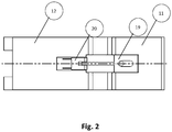
Fig. 2 demonstrates top view of photo coupler and photo interrupter pair according to the present invention. -
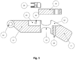
Fig. 3a demonstrates top view of a photo interrupter having a photo interrupter mounting channel and an integral beam blocker according to the present invention. -
Fig. 3b demonstrates isometric view of the photo interrupter according to the present invention. -
Fig. 3c demonstrates side view of the photo interrupter according to the present invention. -
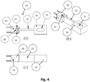
Fig. 4a demonstrates top view of the photo coupler and photo interrupter coupled thereto, having photo interrupter mounting channel, beam blocker, light source, light sensing unit and photo coupler channel according to the present invention. -
Fig. 4b demonstrates isometric view of the photo coupler coupled with the photo interrupter according to the present invention. -
Fig. 4c demonstrates side view of the photo coupler together with the photo interrupter according to the present invention. -
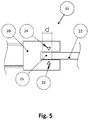
Fig. 5 demonstrates an enlarged top view of the photo coupler together with the photo interrupter according to the present invention. -
Fig. 6a demonstrates top view of the photo coupler having the light source, light sensing unit and photo coupler channel according to the present invention. -
Fig. 6b demonstrates isometric view of the photo coupler according to the present invention. -
Fig. 6c demonstrates side view of the photo coupler according to the present invention. -
Fig. 7a demonstrates top view of a distal phalange segment connected with an intermediate phalange segment through the flexural distal inter-phalangeal joint.Fig. 7b and 7c respectively depict isometric and side views of the two segments according to the present invention. -
Fig. 8a, 8b, and 8c demonstrate a pair of segments in the form of a distal phalange segment connected with an intermediate phalange segment and an additional pair of an inner distal phalange segment connected with an inner intermediate phalange segment through a flexural linear inter-phalangeal joint. -
Fig. 9a, 9b, 9c and 9d demonstrate an artificial hand in different views; namely front, side, isometric and top view are shown according to the present invention. - The following numerals are referred to in the detailed description of the present invention:
- 10) Contact force sensor
- 11) Distal phalange segment
- 12) Intermediate phalange segment
- 13) Flexural distal inter-phalangeal joint
- 14) Proximal inter-phalangeal joint
- 15) Photo coupler housing
- 16) Photo coupler mounting slot
- 17) Photo interrupter housing
- 18) Photo interrupter mounting slot
- 19) Photo interrupter
- 20) Photo coupler
- 21) Photo interrupter mounting channel
- 22) Beam blocker
- 23) Light source
- 24) Light sensing unit
- 25) Photo coupler channel
- 26) Finger root structure
- 27) Inner distal phalange segment
- 28) Inner intermediate phalange segment
- 29) Flexural linear inter-phalangeal joint
- 30) Artificial hand
- 31) Inner proximal phalangeal joint
- 32) Inner photo-interrupter
- 33) Inner photo-coupler
- The present invention discloses an artificial hand (30) having a distal phalange segment (11), an intermediate phalange segment (12), a flexural distal inter-phalangeal joint (DIP joint) (13) and a proximal inter-phalangeal joint (14) designed in a way that they simulate functioning of a human hand fingers. The distal phalange segment (11) is connected to said intermediate phalange segment (12) through said flexural distal inter-phalangeal joint (13). The sensing elements that will be explained hereinafter detect the deflection of said semi-rigid flexural distal inter-phalangeal joint (13) caused by the force exerted on the outermost tip of the distal phalange segment (11).
- The distal phalange segment (11) of the invention, which constitutes the outer tip of the artificial hand (30), comprises a photo interrupter housing (17) and a photo interrupter mounting slot (18). The photo interrupter housing (17) is occupied by the photo interrupter (19) placed therein and it is designed as a generally linear channel to partly enclose said photo interrupter (19). The photo interrupter housing's (17) photo interrupter mounting slot (18) is configured in the manner that the photo interrupter (19) is removably installed to be movable in a photo coupler channel (25). In a more specific manner, when the distal phalange segment (11) undergoes a rotational movement relative to said intermediate phalange segment (12) due to the flexibility of said flexural distal inter-phalangeal joint (13), said photo interrupter (19) is imparted a certain amount of movement in the direction of said photo coupler channel (25) as its distal end is fixedly attached to the distal phalange segment (11) within the photo interrupter housing (17).
- The intermediate phalange segment (12) of the invention is connected to the distal phalange segment (11) through said flexural distal inter-phalangeal joint (13) and comprises a photo coupler housing (15) and a photo coupler mounting slot (16). The photo coupler housing (15) contains a photo coupler (20) to be fixedly placed therein. The photo coupler housing (15) acts as a channel maintaining said photo coupler (20). The photo coupler housing (15) further has photo coupler mounting slots (16) which serve to the purpose of fixating said photo coupler (20) within said photo coupler housing (15). The photo interrupter (19) and the photo coupler (20) together form the contact force sensor (10) of the present invention. The artificial hand (30) of the invention is therefore composed of the above-identified individual elements interacting with each other to create the reciprocally induced set of actions.
- Basically, the photo coupler housing (15) is formed as a cavity on the intermediate phalange segment (12), preserving the photo coupler (20) while the photo interrupter housing (17) is created on the distal phalange segment (11) and in between the photo coupler (20) and photo interrupter (19) lies the semi rigid flexural distal inter-phalangeal joint (13) that bends with a certain rate "k" causing the photo-interrupter to deflect "θ" when a force "F" is exerted on the tip of the finger. So the net force can be calculated using Hook's law.
- The force on the tip of the contact force sensor (10) causes the flexural distal inter-phalangeal joint (13) to bend in the direction of the force; therefore, resulting the photo interrupter (19) to move into said photo coupler channel (25), thereby blocking the light received from a light source (23) to reach the window of a light sensing unit (24), decreasing the output signal of the photo coupler (20). The light source (23) can typically be an LED while said light sensing unit (24) is a photo-transistor.
- The photo interrupter (19) comprises a photo interrupter mounting channel (21) and a beam blocker (22). The photo interrupter mounting channel (21) typically allows fixation of the photo interrupter (19) into said photo interrupter housing (17) through any appropriate connection means such as screws. The beam blocker (22) is a longitudinal extension with a sufficiently thin transversal dimension to fit the photo coupler channel (25). It basically provides that, depending on its positionment on its longitudinal direction, some amount of the light is blocked from reaching the light sensing unit (24) when said beam blocker (22), movable in accordance with the flexibly supported rotational movement of the distal phalange segment (11), is introduced into said photo coupler channel (25). The photo interrupter mounting channel (21) allows to set the initial position of the photo interrupter (19) and thereby the calibrated amount of light reaching the light sensing unit (24) in no load conditions.
- The light source (23) and the light sensing unit (24) are typically facing each other along the same direction. The photo interrupter (19) is adapted to be aligned for insertion into the photo coupler channel (25) of the photo coupler (20) in order to be displaced therein for effecting blockage of the light emitted by the light source (23). The beam blocker (22) being movable relative to the photo coupler channel (25), a substantially limited movement thereof will cause the blockage of the light. The distance "d" as shown by the dashed lines in
Fig. 5 is representative of the amount of the tip portion's displacement as the maximum amount of blockage of the LED light from 0% to 100%. Therefore, an electronic control unit is able to calculate the exact amount of blockage in accordance with the final position of the tip portion. - In a variation of the present invention, an additional pair of an inner distal phalange segment (27) and an inner intermediate phalange segment (28) can be attached to each other via a flexural linear inter-phalangeal joint (29), this inner pair of cooperating elements being connected with the outer pair of said distal phalange segment (11) and said intermediate phalange segment (12) through the proximal inter-phalangeal joint (14). More precisely, the outer pair of finger segments in the robotic/artificial hand (30) is connected with an additional inner pair to provide a four-segment artificial hand (30) finger. Both pair of finger segments form a longitudinal artificial hand (30) finger attached to a finger root structure (26) from which, a plurality of separate fingers typically extend.
- According to this embodiment of the present invention, a certain amount of rotational movement of the distal phalange segment (11) around said flexural distal inter-phalangeal joint (13) can cause linear displacement of an inner photo-interrupter (32) disposed between said inner distal phalange segment (27) and said inner intermediate phalange segment (28). It is to be noted that the pair of distal phalange segment-intermediate phalange segment (11-12) is connected to the pair of inner distal phalange segment-inner intermediate phalange segment (27-28) through the rotary proximal inter-phalangeal joint (14) and the latter will prevent transmission of any rotational movement to the inner pair of inner distal phalange segment-inner intermediate phalange segment (27-28). On the other hand, as the flexure means, namely the flexural linear inter-phalangeal joint (29) disposed between the inner pair components can undergo linear stretching in response to rotational movement of the distal phalange segment (11) beyond a predetermined level, the inner photo-interrupter (32) movable in and out relative to an inner photo-coupler's (33) respective channel receiving a respective beam blocker.
- It is therefore to be noted that the stretching out of the flexural linear inter-phalangeal joint (29) extending linearly in longitudinal dimension is sensed by said inner photo-coupler's (33) cooperating with said inner photo-interrupter (33). The electronic control unit therefore uses the additional information, namely the positionment of the inner beam blocker relative to the inner photo coupler to be combined with the information obtained from the pair of photo interrupter-photo coupler (19-20) around said flexural distal inter-phalangeal joint (13). The additional stretching out of the flexural distal inter-phalangeal joint (13) signifies an even greater amount of contact force and is thereby construed as a direct indication for interrupting driving mechanisms (such as electric motors), typically effective in effectuating rotation of the finger segments around said proximal inter-phalangeal joints (14) and said inner proximal phalangeal joints (31).
- In a nutshell, the present invention proposes an artificial hand (30) having a plurality of artificial finger, each artificial finger comprising a flexural distal inter-phalangeal joint (13) disposed between a distal phalange segment (11) and an intermediate phalange segment (12), said intermediate phalange segment (12) being connected with a proximal inter-phalangeal joint (14) around which said intermediate phalange segment (12) is rotatable to displace said distal phalange segment (11).
- According to one embodiment of the present invention, a photo interrupter (19) having a beam blocker (22) longitudinally extends through the flexural distal inter-phalangeal joint (13) to a photo coupler channel (25) of a photo coupler (20), each of said photo interrupter (19) and said photo coupler (20) being respectively disposable at one longitudinal side of said flexural distal inter-phalangeal joint (13) either on the distal phalange segment (11) or the intermediate phalange segment (12).
- According to a further embodiment of the present invention, said photo coupler (20) consists of a light source (23) and a light sensing unit (24) in optical communication with each other in the manner that optical communication between the light source (23) and the light sensing unit (24) is gradually interruptable in response to displacement of said beam blocker (22) within said photo coupler channel (25) upon rotational movement of said phalange segment (11) around said flexural distal inter-phalangeal joint (13).
- According to a still further embodiment of the present invention, the distal phalange segment (11) comprises the photo interrupter (19) with the beam blocker (22) longitudinally extending from said distal phalange segment (11) through the flexural distal inter-phalangeal joint (13) to the photo coupler channel (25) of the photo coupler (20) of said intermediate phalange segment (12).
- According to a yet still further embodiment of the present invention, the light source (23) and the light sensing unit (24) are in optical communication with each other along an axis perpendicular to the longitudinal direction of said beam blocker (22).
- According to a yet still further embodiment of the present invention, said flexural distal inter-phalangeal joint (13) is configured such that the longitudinal axis of said distal phalange segment (11) is inclined with respect to said intermediate phalange segment (12) whereby rotational deflection of said flexural distal inter-phalangeal joint (13) caused by the force exerted on the outermost tip of the distal phalange segment (11) is detectable.
- According to a yet still further embodiment of the present invention, the distal phalange segment (11) comprises a photo interrupter housing (17) for accommodating said photo interrupter (19).
- According to a yet still further embodiment of the present invention, the photo interrupter (19) is fixedly attached to said photo interrupter housing (17) through a photo interrupter mounting slot (18) in the manner that rotation of the distal phalange segment (11) in the opposite direction against a contacted surface causes displacement of the photo interrupter's (19) beam blocker (22) relative to said photo coupler channel (25) due to the inclined orientation of said flexural distal inter-phalangeal joint (13) between the distal phalange segment (11) and the intermediate phalange segment (12).
- According to a yet still further embodiment of the present invention, the intermediate phalange segment (12) comprises a photo coupler housing (15) in which said photo coupler (20) is fixedly attached.
- According to a yet still further embodiment of the present invention, the light source (23) is an LED and said light sensing unit (24) is a photo-transistor.
- According to a yet still further embodiment of the present invention, a second pair of an inner distal phalange segment (27) and an inner intermediate phalange segment (28) are attached to the first pair of said distal phalange segment (11) and said intermediate phalange segment (12) through the proximal inter-phalangeal joint (14).
- According to a yet still further embodiment of the present invention, said pair of inner distal phalange segment (27) and inner intermediate phalange segment (28) are attached to each other via a flexural linear inter-phalangeal joint (29).
- According to a yet still further embodiment of the present invention, said first and second pair of artificial finger segments form a longitudinal artificial hand (30) finger attached to a finger root structure (26) from which, a plurality of separate artificial fingers extend.
- According to a yet still further embodiment of the present invention, linear stretching out of the flexural linear inter-phalangeal joint (29) between the inner distal phalange segment (27) and the inner intermediate phalange segment (28) is measurable through linear displacement of an inner photo-interrupter (32) relative to an inner photo-coupler (33).
- According to a yet still further embodiment of the present invention, an electronic control unit concurrently measures rotational displacement of said Flexural distal inter-phalangeal joint and linear stretching out of said flexural linear inter-phalangeal joint (29).
- A particular feature, structure, or characteristic described herein in connection with one embodiment may be implemented within other embodiments without departing from the scope of the invention. The dimensional aspects of the beam blocker (22) in different configurations depending on the design of the artificial hand (30). In addition, it is to be noted that the location or arrangement of individual elements within each disclosed embodiment may be modified without departing from the scope of the invention. The detailed description is, therefore, not to be taken in a limiting sense, and the scope of the present invention is defined only by the appended claims to be interpreted along with the full range of equivalents to which the claims are entitled.
Claims (13)
- An artificial hand (30) having a plurality of artificial fingers, each artificial finger comprising a flexural distal inter-phalangeal joint (13) disposed between a distal phalange segment (11) and an intermediate phalange segment (12), said intermediate phalange segment (12) being connected with a proximal inter-phalangeal joint (14) around which said intermediate phalange segment (12) is rotatable to displace said distal phalange segment (11) characterized in that;
a photo interrupter (19) having a beam blocker (22) longitudinally extends through the flexural distal inter-phalangeal joint (13) to a photo coupler channel (25) of a photo coupler (20), each of said photo interrupter (19) and said photo coupler (20) being respectively disposable at one longitudinal side of said flexural distal inter-phalangeal joint (13) either on the distal phalange segment (11) or the intermediate phalange segment (12),
said photo coupler (20) consists of a light source (23) and a light sensing unit (24) in optical communication with each other in the manner that optical communication between the light source (23) and the light sensing unit (24) is gradually interruptable in response to displacement of said beam blocker (22) within said photo coupler channel (25) upon rotational movement of said phalange segment (11) around said flexural distal inter-phalangeal joint (13). - An artificial hand (30) as set forth in Claim 1, characterized in that the distal phalange segment (11) comprises the photo interrupter (19) with the beam blocker (22) longitudinally extending from said distal phalange segment (11) through the flexural distal inter-phalangeal joint (13) to the photo coupler channel (25) of the photo coupler (20) of said intermediate phalange segment (12).
- An artificial hand (30) as set forth in Claim 2, characterized in that the light source (23) and the light sensing unit (24) are in optical communication with each other along an axis perpendicular to the longitudinal direction of said beam blocker (22).
- An artificial hand (30) as set forth in Claim 2, characterized in that said flexural distal inter-phalangeal joint (13) is configured such that the longitudinal axis of said distal phalange segment (11) is inclined with respect to said intermediate phalange segment (12) whereby rotational deflection of said flexural distal inter-phalangeal joint (13) caused by the force exerted on the outermost tip of the distal phalange segment (11) is detectable.
- An artificial hand (30) as set forth in Claim 2, characterized in that the distal phalange segment (11) comprises a photo interrupter housing (17) for accommodating said photo interrupter (19).
- An artificial hand (30) as set forth in Claim 4, characterized in that the photo interrupter (19) is fixedly attached to said photo interrupter housing (17) through a photo interrupter mounting slot (18) in the manner that rotation of the distal phalange segment (11) in the opposite direction against a contacted surface causes displacement of the photo interrupter's (19) beam blocker (22) relative to said photo coupler channel (25).
- An artificial hand (30) as set forth in Claim 2 or 6, characterized in that the intermediate phalange segment (12) comprises a photo coupler housing (15) in which said photo coupler (20) is fixedly attached.
- An artificial hand (30) as set forth in any preceding Claim, characterized in that the light source (23) is an LED and said light sensing unit (24) is a photo-transistor.
- An artificial hand (30) as set forth in any preceding Claim, characterized in that a second pair of an inner distal phalange segment (27) and an inner intermediate phalange segment (28) are attached to the first pair of said distal phalange segment (11) and said intermediate phalange segment (12) through the proximal inter-phalangeal joint (14).
- An artificial hand (30) as set forth in Claim 9, characterized in that said pair of inner distal phalange segment (27) and inner intermediate phalange segment (28) are attached to each other via a flexural linear inter-phalangeal joint (29).
- An artificial hand (30) as set forth in Claim 9 or 10, characterized in that said first and second pair of artificial finger segments form a longitudinal artificial hand (30) finger attached to a finger root structure (26) from which, a plurality of separate artificial fingers extend.
- An artificial hand (30) as set forth in Claim 10, characterized in that linear stretching out of the flexural linear inter-phalangeal joint (29) between the inner distal phalange segment (27) and the inner intermediate phalange segment (28) is measurable through linear displacement of an inner photo-interrupter (32) relative to an inner photo-coupler (33).
- An artificial hand (30) as set forth in Claim 12, characterized in that an electronic control unit concurrently measures rotational displacement of said Flexural distal inter-phalangeal joint and linear stretching out of said flexural linear inter-phalangeal joint (29).
Applications Claiming Priority (1)
| Application Number | Priority Date | Filing Date | Title |
|---|---|---|---|
| PCT/TR2016/050145 WO2017200495A1 (en) | 2016-05-16 | 2016-05-16 | Artificial hand having finger units provided with a photo coupler contact force sensor |
Publications (2)
| Publication Number | Publication Date |
|---|---|
| EP3458236A1 EP3458236A1 (en) | 2019-03-27 |
| EP3458236B1 true EP3458236B1 (en) | 2020-08-26 |
Family
ID=56373106
Family Applications (1)
| Application Number | Title | Priority Date | Filing Date |
|---|---|---|---|
| EP16736641.8A Active EP3458236B1 (en) | 2016-05-16 | 2016-05-16 | Artificial hand having finger units provided with a photo coupler contact force sensor |
Country Status (2)
| Country | Link |
|---|---|
| EP (1) | EP3458236B1 (en) |
| WO (1) | WO2017200495A1 (en) |
Families Citing this family (2)
| Publication number | Priority date | Publication date | Assignee | Title |
|---|---|---|---|---|
| US11435244B2 (en) * | 2017-11-30 | 2022-09-06 | Koc Universitesi | Force sensor for measuring static and dynamic friction coefficients |
| EP3749258B1 (en) | 2018-02-07 | 2026-01-07 | KOC Universitesi | A prosthetic hand |
Family Cites Families (5)
| Publication number | Priority date | Publication date | Assignee | Title |
|---|---|---|---|---|
| US3904234A (en) * | 1973-10-15 | 1975-09-09 | Stanford Research Inst | Manipulator with electromechanical transducer means |
| BE1004980A3 (en) | 1991-06-18 | 1993-03-09 | Univ Bruxelles | Force sensor and use thereof on a robot. |
| US5376785A (en) * | 1992-10-02 | 1994-12-27 | Chin; Philip K. | Optical displacement sensor utilizing optical diffusion |
| JP4390126B2 (en) * | 2002-06-17 | 2009-12-24 | 独立行政法人科学技術振興機構 | High-sensitivity torque sensor adjustment method applicable to robot finger joints, etc. |
| US8231158B2 (en) * | 2006-11-03 | 2012-07-31 | President And Fellows Of Harvard College | Robust compliant adaptive grasper and method of manufacturing same |
-
2016
- 2016-05-16 WO PCT/TR2016/050145 patent/WO2017200495A1/en not_active Ceased
- 2016-05-16 EP EP16736641.8A patent/EP3458236B1/en active Active
Non-Patent Citations (1)
| Title |
|---|
| None * |
Also Published As
| Publication number | Publication date |
|---|---|
| WO2017200495A1 (en) | 2017-11-23 |
| EP3458236A1 (en) | 2019-03-27 |
Similar Documents
| Publication | Publication Date | Title |
|---|---|---|
| AU2020250296B2 (en) | User interface devices for use in robotic surgery | |
| AU2019270647B2 (en) | Master controller assembly for a robotic surgery system, particularly for microsurgery | |
| US10105188B2 (en) | Arm with a combined force and shape sensor | |
| US6127672A (en) | Topological and motion measuring tool | |
| JP2023508559A (en) | Surgical instrument with feedback control circuit | |
| JP2023508532A (en) | Surgical instrument with sensing system | |
| JP2023509424A (en) | Surgical instrument with flex circuit | |
| US6110130A (en) | Exoskeleton device for directly measuring fingertip position and inferring finger joint angle | |
| JP2023508556A (en) | Surgical instrument with signal interferometry resolution system | |
| EP2281515B1 (en) | Surgical instrument | |
| JP2023508577A (en) | Surgical instrument with flex circuit including sensor system | |
| Berselli et al. | Integrated mechatronic design for a new generation of robotic hands | |
| KR20080089582A (en) | How to detect force and torque on surgical instruments | |
| WO1998024017A2 (en) | Control means | |
| WO2017200495A1 (en) | Artificial hand having finger units provided with a photo coupler contact force sensor | |
| EP3747605A1 (en) | Sensor module and robot system | |
| US9924855B2 (en) | Endoscopic instrument | |
| US20180049831A1 (en) | Medical manipulator system | |
| KR101835097B1 (en) | Wearable interface device using piezoelectric element | |
| KR20100134983A (en) | Wearing robot for hand movement of handicapped person | |
| WO2020246008A1 (en) | Tactile sensor, robot hand, and robot | |
| US20080004493A1 (en) | Device for Changing the Acting Direction of an Instrument | |
| US9526406B2 (en) | Endoscopic instrument | |
| KR20070071537A (en) | 2 degree of freedom myoelectric gripping sensor sliding sensor and control device | |
| JPH10221184A (en) | Torque sensor |
Legal Events
| Date | Code | Title | Description |
|---|---|---|---|
| STAA | Information on the status of an ep patent application or granted ep patent |
Free format text: STATUS: THE INTERNATIONAL PUBLICATION HAS BEEN MADE |
|
| PUAI | Public reference made under article 153(3) epc to a published international application that has entered the european phase |
Free format text: ORIGINAL CODE: 0009012 |
|
| STAA | Information on the status of an ep patent application or granted ep patent |
Free format text: STATUS: REQUEST FOR EXAMINATION WAS MADE |
|
| 17P | Request for examination filed |
Effective date: 20190130 |
|
| AK | Designated contracting states |
Kind code of ref document: A1 Designated state(s): AL AT BE BG CH CY CZ DE DK EE ES FI FR GB GR HR HU IE IS IT LI LT LU LV MC MK MT NL NO PL PT RO RS SE SI SK SM TR |
|
| AX | Request for extension of the european patent |
Extension state: BA ME |
|
| DAV | Request for validation of the european patent (deleted) | ||
| DAX | Request for extension of the european patent (deleted) | ||
| GRAP | Despatch of communication of intention to grant a patent |
Free format text: ORIGINAL CODE: EPIDOSNIGR1 |
|
| STAA | Information on the status of an ep patent application or granted ep patent |
Free format text: STATUS: GRANT OF PATENT IS INTENDED |
|
| INTG | Intention to grant announced |
Effective date: 20200402 |
|
| GRAS | Grant fee paid |
Free format text: ORIGINAL CODE: EPIDOSNIGR3 |
|
| GRAA | (expected) grant |
Free format text: ORIGINAL CODE: 0009210 |
|
| STAA | Information on the status of an ep patent application or granted ep patent |
Free format text: STATUS: THE PATENT HAS BEEN GRANTED |
|
| AK | Designated contracting states |
Kind code of ref document: B1 Designated state(s): AL AT BE BG CH CY CZ DE DK EE ES FI FR GB GR HR HU IE IS IT LI LT LU LV MC MK MT NL NO PL PT RO RS SE SI SK SM TR |
|
| REG | Reference to a national code |
Ref country code: GB Ref legal event code: FG4D |
|
| REG | Reference to a national code |
Ref country code: CH Ref legal event code: EP |
|
| REG | Reference to a national code |
Ref country code: AT Ref legal event code: REF Ref document number: 1305924 Country of ref document: AT Kind code of ref document: T Effective date: 20200915 |
|
| REG | Reference to a national code |
Ref country code: IE Ref legal event code: FG4D |
|
| REG | Reference to a national code |
Ref country code: DE Ref legal event code: R096 Ref document number: 602016042748 Country of ref document: DE |
|
| REG | Reference to a national code |
Ref country code: LT Ref legal event code: MG4D |
|
| PG25 | Lapsed in a contracting state [announced via postgrant information from national office to epo] |
Ref country code: FI Free format text: LAPSE BECAUSE OF FAILURE TO SUBMIT A TRANSLATION OF THE DESCRIPTION OR TO PAY THE FEE WITHIN THE PRESCRIBED TIME-LIMIT Effective date: 20200826 Ref country code: HR Free format text: LAPSE BECAUSE OF FAILURE TO SUBMIT A TRANSLATION OF THE DESCRIPTION OR TO PAY THE FEE WITHIN THE PRESCRIBED TIME-LIMIT Effective date: 20200826 Ref country code: SE Free format text: LAPSE BECAUSE OF FAILURE TO SUBMIT A TRANSLATION OF THE DESCRIPTION OR TO PAY THE FEE WITHIN THE PRESCRIBED TIME-LIMIT Effective date: 20200826 Ref country code: GR Free format text: LAPSE BECAUSE OF FAILURE TO SUBMIT A TRANSLATION OF THE DESCRIPTION OR TO PAY THE FEE WITHIN THE PRESCRIBED TIME-LIMIT Effective date: 20201127 Ref country code: PT Free format text: LAPSE BECAUSE OF FAILURE TO SUBMIT A TRANSLATION OF THE DESCRIPTION OR TO PAY THE FEE WITHIN THE PRESCRIBED TIME-LIMIT Effective date: 20201228 Ref country code: NO Free format text: LAPSE BECAUSE OF FAILURE TO SUBMIT A TRANSLATION OF THE DESCRIPTION OR TO PAY THE FEE WITHIN THE PRESCRIBED TIME-LIMIT Effective date: 20201126 Ref country code: LT Free format text: LAPSE BECAUSE OF FAILURE TO SUBMIT A TRANSLATION OF THE DESCRIPTION OR TO PAY THE FEE WITHIN THE PRESCRIBED TIME-LIMIT Effective date: 20200826 Ref country code: BG Free format text: LAPSE BECAUSE OF FAILURE TO SUBMIT A TRANSLATION OF THE DESCRIPTION OR TO PAY THE FEE WITHIN THE PRESCRIBED TIME-LIMIT Effective date: 20201126 |
|
| REG | Reference to a national code |
Ref country code: NL Ref legal event code: MP Effective date: 20200826 |
|
| REG | Reference to a national code |
Ref country code: AT Ref legal event code: MK05 Ref document number: 1305924 Country of ref document: AT Kind code of ref document: T Effective date: 20200826 |
|
| PG25 | Lapsed in a contracting state [announced via postgrant information from national office to epo] |
Ref country code: PL Free format text: LAPSE BECAUSE OF FAILURE TO SUBMIT A TRANSLATION OF THE DESCRIPTION OR TO PAY THE FEE WITHIN THE PRESCRIBED TIME-LIMIT Effective date: 20200826 Ref country code: NL Free format text: LAPSE BECAUSE OF FAILURE TO SUBMIT A TRANSLATION OF THE DESCRIPTION OR TO PAY THE FEE WITHIN THE PRESCRIBED TIME-LIMIT Effective date: 20200826 Ref country code: LV Free format text: LAPSE BECAUSE OF FAILURE TO SUBMIT A TRANSLATION OF THE DESCRIPTION OR TO PAY THE FEE WITHIN THE PRESCRIBED TIME-LIMIT Effective date: 20200826 Ref country code: RS Free format text: LAPSE BECAUSE OF FAILURE TO SUBMIT A TRANSLATION OF THE DESCRIPTION OR TO PAY THE FEE WITHIN THE PRESCRIBED TIME-LIMIT Effective date: 20200826 Ref country code: IS Free format text: LAPSE BECAUSE OF FAILURE TO SUBMIT A TRANSLATION OF THE DESCRIPTION OR TO PAY THE FEE WITHIN THE PRESCRIBED TIME-LIMIT Effective date: 20201226 |
|
| PG25 | Lapsed in a contracting state [announced via postgrant information from national office to epo] |
Ref country code: EE Free format text: LAPSE BECAUSE OF FAILURE TO SUBMIT A TRANSLATION OF THE DESCRIPTION OR TO PAY THE FEE WITHIN THE PRESCRIBED TIME-LIMIT Effective date: 20200826 Ref country code: RO Free format text: LAPSE BECAUSE OF FAILURE TO SUBMIT A TRANSLATION OF THE DESCRIPTION OR TO PAY THE FEE WITHIN THE PRESCRIBED TIME-LIMIT Effective date: 20200826 Ref country code: SM Free format text: LAPSE BECAUSE OF FAILURE TO SUBMIT A TRANSLATION OF THE DESCRIPTION OR TO PAY THE FEE WITHIN THE PRESCRIBED TIME-LIMIT Effective date: 20200826 Ref country code: CZ Free format text: LAPSE BECAUSE OF FAILURE TO SUBMIT A TRANSLATION OF THE DESCRIPTION OR TO PAY THE FEE WITHIN THE PRESCRIBED TIME-LIMIT Effective date: 20200826 Ref country code: DK Free format text: LAPSE BECAUSE OF FAILURE TO SUBMIT A TRANSLATION OF THE DESCRIPTION OR TO PAY THE FEE WITHIN THE PRESCRIBED TIME-LIMIT Effective date: 20200826 |
|
| REG | Reference to a national code |
Ref country code: DE Ref legal event code: R097 Ref document number: 602016042748 Country of ref document: DE |
|
| PG25 | Lapsed in a contracting state [announced via postgrant information from national office to epo] |
Ref country code: ES Free format text: LAPSE BECAUSE OF FAILURE TO SUBMIT A TRANSLATION OF THE DESCRIPTION OR TO PAY THE FEE WITHIN THE PRESCRIBED TIME-LIMIT Effective date: 20200826 Ref country code: AL Free format text: LAPSE BECAUSE OF FAILURE TO SUBMIT A TRANSLATION OF THE DESCRIPTION OR TO PAY THE FEE WITHIN THE PRESCRIBED TIME-LIMIT Effective date: 20200826 Ref country code: AT Free format text: LAPSE BECAUSE OF FAILURE TO SUBMIT A TRANSLATION OF THE DESCRIPTION OR TO PAY THE FEE WITHIN THE PRESCRIBED TIME-LIMIT Effective date: 20200826 |
|
| PG25 | Lapsed in a contracting state [announced via postgrant information from national office to epo] |
Ref country code: SK Free format text: LAPSE BECAUSE OF FAILURE TO SUBMIT A TRANSLATION OF THE DESCRIPTION OR TO PAY THE FEE WITHIN THE PRESCRIBED TIME-LIMIT Effective date: 20200826 |
|
| PLBE | No opposition filed within time limit |
Free format text: ORIGINAL CODE: 0009261 |
|
| STAA | Information on the status of an ep patent application or granted ep patent |
Free format text: STATUS: NO OPPOSITION FILED WITHIN TIME LIMIT |
|
| PG25 | Lapsed in a contracting state [announced via postgrant information from national office to epo] |
Ref country code: IT Free format text: LAPSE BECAUSE OF FAILURE TO SUBMIT A TRANSLATION OF THE DESCRIPTION OR TO PAY THE FEE WITHIN THE PRESCRIBED TIME-LIMIT Effective date: 20200826 |
|
| 26N | No opposition filed |
Effective date: 20210527 |
|
| PG25 | Lapsed in a contracting state [announced via postgrant information from national office to epo] |
Ref country code: SI Free format text: LAPSE BECAUSE OF FAILURE TO SUBMIT A TRANSLATION OF THE DESCRIPTION OR TO PAY THE FEE WITHIN THE PRESCRIBED TIME-LIMIT Effective date: 20200826 |
|
| PG25 | Lapsed in a contracting state [announced via postgrant information from national office to epo] |
Ref country code: LU Free format text: LAPSE BECAUSE OF NON-PAYMENT OF DUE FEES Effective date: 20210516 Ref country code: MC Free format text: LAPSE BECAUSE OF FAILURE TO SUBMIT A TRANSLATION OF THE DESCRIPTION OR TO PAY THE FEE WITHIN THE PRESCRIBED TIME-LIMIT Effective date: 20200826 |
|
| REG | Reference to a national code |
Ref country code: BE Ref legal event code: MM Effective date: 20210531 |
|
| PG25 | Lapsed in a contracting state [announced via postgrant information from national office to epo] |
Ref country code: IE Free format text: LAPSE BECAUSE OF NON-PAYMENT OF DUE FEES Effective date: 20210516 |
|
| PG25 | Lapsed in a contracting state [announced via postgrant information from national office to epo] |
Ref country code: BE Free format text: LAPSE BECAUSE OF NON-PAYMENT OF DUE FEES Effective date: 20210531 |
|
| PG25 | Lapsed in a contracting state [announced via postgrant information from national office to epo] |
Ref country code: CY Free format text: LAPSE BECAUSE OF FAILURE TO SUBMIT A TRANSLATION OF THE DESCRIPTION OR TO PAY THE FEE WITHIN THE PRESCRIBED TIME-LIMIT Effective date: 20200826 |
|
| PG25 | Lapsed in a contracting state [announced via postgrant information from national office to epo] |
Ref country code: HU Free format text: LAPSE BECAUSE OF FAILURE TO SUBMIT A TRANSLATION OF THE DESCRIPTION OR TO PAY THE FEE WITHIN THE PRESCRIBED TIME-LIMIT; INVALID AB INITIO Effective date: 20160516 |
|
| PGFP | Annual fee paid to national office [announced via postgrant information from national office to epo] |
Ref country code: FR Payment date: 20230531 Year of fee payment: 8 Ref country code: CH Payment date: 20230602 Year of fee payment: 8 |
|
| PG25 | Lapsed in a contracting state [announced via postgrant information from national office to epo] |
Ref country code: MK Free format text: LAPSE BECAUSE OF FAILURE TO SUBMIT A TRANSLATION OF THE DESCRIPTION OR TO PAY THE FEE WITHIN THE PRESCRIBED TIME-LIMIT Effective date: 20200826 |
|
| PG25 | Lapsed in a contracting state [announced via postgrant information from national office to epo] |
Ref country code: MT Free format text: LAPSE BECAUSE OF FAILURE TO SUBMIT A TRANSLATION OF THE DESCRIPTION OR TO PAY THE FEE WITHIN THE PRESCRIBED TIME-LIMIT Effective date: 20200826 |
|
| REG | Reference to a national code |
Ref country code: CH Ref legal event code: PL |
|
| PG25 | Lapsed in a contracting state [announced via postgrant information from national office to epo] |
Ref country code: CH Free format text: LAPSE BECAUSE OF NON-PAYMENT OF DUE FEES Effective date: 20240531 |
|
| PG25 | Lapsed in a contracting state [announced via postgrant information from national office to epo] |
Ref country code: FR Free format text: LAPSE BECAUSE OF NON-PAYMENT OF DUE FEES Effective date: 20240531 |
|
| PGFP | Annual fee paid to national office [announced via postgrant information from national office to epo] |
Ref country code: DE Payment date: 20250528 Year of fee payment: 10 |
|
| PGFP | Annual fee paid to national office [announced via postgrant information from national office to epo] |
Ref country code: GB Payment date: 20250520 Year of fee payment: 10 |
|
| PGFP | Annual fee paid to national office [announced via postgrant information from national office to epo] |
Ref country code: TR Payment date: 20250509 Year of fee payment: 10 |