EP3458010B1 - Patient support pad - Google Patents
Patient support pad Download PDFInfo
- Publication number
- EP3458010B1 EP3458010B1 EP17799882.0A EP17799882A EP3458010B1 EP 3458010 B1 EP3458010 B1 EP 3458010B1 EP 17799882 A EP17799882 A EP 17799882A EP 3458010 B1 EP3458010 B1 EP 3458010B1
- Authority
- EP
- European Patent Office
- Prior art keywords
- support pad
- cushion layer
- sensing
- portions
- sensing device
- Prior art date
- Legal status (The legal status is an assumption and is not a legal conclusion. Google has not performed a legal analysis and makes no representation as to the accuracy of the status listed.)
- Active
Links
Images


Classifications
-
- A—HUMAN NECESSITIES
- A61—MEDICAL OR VETERINARY SCIENCE; HYGIENE
- A61B—DIAGNOSIS; SURGERY; IDENTIFICATION
- A61B5/00—Measuring for diagnostic purposes; Identification of persons
- A61B5/44—Detecting, measuring or recording for evaluating the integumentary system, e.g. skin, hair or nails
- A61B5/441—Skin evaluation, e.g. for skin disorder diagnosis
- A61B5/447—Skin evaluation, e.g. for skin disorder diagnosis specially adapted for aiding the prevention of ulcer or pressure sore development, i.e. before the ulcer or sore has developed
-
- A—HUMAN NECESSITIES
- A61—MEDICAL OR VETERINARY SCIENCE; HYGIENE
- A61G—TRANSPORT, PERSONAL CONVEYANCES, OR ACCOMMODATION SPECIALLY ADAPTED FOR PATIENTS OR DISABLED PERSONS; OPERATING TABLES OR CHAIRS; CHAIRS FOR DENTISTRY; FUNERAL DEVICES
- A61G13/00—Operating tables; Auxiliary appliances therefor
- A61G13/10—Parts, details or accessories
-
- A—HUMAN NECESSITIES
- A47—FURNITURE; DOMESTIC ARTICLES OR APPLIANCES; COFFEE MILLS; SPICE MILLS; SUCTION CLEANERS IN GENERAL
- A47C—CHAIRS; SOFAS; BEDS
- A47C21/00—Attachments for beds, e.g. sheet holders or bed-cover holders; Ventilating, cooling or heating means in connection with bedsteads or mattresses
- A47C21/04—Devices for ventilating, cooling or heating
- A47C21/048—Devices for ventilating, cooling or heating for heating
-
- A—HUMAN NECESSITIES
- A47—FURNITURE; DOMESTIC ARTICLES OR APPLIANCES; COFFEE MILLS; SPICE MILLS; SUCTION CLEANERS IN GENERAL
- A47C—CHAIRS; SOFAS; BEDS
- A47C27/00—Spring, stuffed or fluid mattresses or cushions specially adapted for chairs, beds or sofas
- A47C27/001—Spring, stuffed or fluid mattresses or cushions specially adapted for chairs, beds or sofas with several cushions, mattresses or the like, to be put together in one cover
-
- A—HUMAN NECESSITIES
- A47—FURNITURE; DOMESTIC ARTICLES OR APPLIANCES; COFFEE MILLS; SPICE MILLS; SUCTION CLEANERS IN GENERAL
- A47C—CHAIRS; SOFAS; BEDS
- A47C27/00—Spring, stuffed or fluid mattresses or cushions specially adapted for chairs, beds or sofas
- A47C27/14—Spring, stuffed or fluid mattresses or cushions specially adapted for chairs, beds or sofas with foamed material inlays
- A47C27/15—Spring, stuffed or fluid mattresses or cushions specially adapted for chairs, beds or sofas with foamed material inlays consisting of two or more layers
-
- A—HUMAN NECESSITIES
- A61—MEDICAL OR VETERINARY SCIENCE; HYGIENE
- A61G—TRANSPORT, PERSONAL CONVEYANCES, OR ACCOMMODATION SPECIALLY ADAPTED FOR PATIENTS OR DISABLED PERSONS; OPERATING TABLES OR CHAIRS; CHAIRS FOR DENTISTRY; FUNERAL DEVICES
- A61G13/00—Operating tables; Auxiliary appliances therefor
- A61G13/10—Parts, details or accessories
- A61G13/12—Rests specially adapted therefor; Arrangements of patient-supporting surfaces
- A61G13/126—Rests specially adapted therefor; Arrangements of patient-supporting surfaces with specific supporting surface
-
- A—HUMAN NECESSITIES
- A61—MEDICAL OR VETERINARY SCIENCE; HYGIENE
- A61G—TRANSPORT, PERSONAL CONVEYANCES, OR ACCOMMODATION SPECIALLY ADAPTED FOR PATIENTS OR DISABLED PERSONS; OPERATING TABLES OR CHAIRS; CHAIRS FOR DENTISTRY; FUNERAL DEVICES
- A61G7/00—Beds specially adapted for nursing; Devices for lifting patients or disabled persons
- A61G7/05—Parts, details or accessories of beds
- A61G7/0527—Weighing devices
-
- A—HUMAN NECESSITIES
- A61—MEDICAL OR VETERINARY SCIENCE; HYGIENE
- A61G—TRANSPORT, PERSONAL CONVEYANCES, OR ACCOMMODATION SPECIALLY ADAPTED FOR PATIENTS OR DISABLED PERSONS; OPERATING TABLES OR CHAIRS; CHAIRS FOR DENTISTRY; FUNERAL DEVICES
- A61G7/00—Beds specially adapted for nursing; Devices for lifting patients or disabled persons
- A61G7/05—Parts, details or accessories of beds
- A61G7/057—Arrangements for preventing bed-sores or for supporting patients with burns, e.g. mattresses specially adapted therefor
-
- A—HUMAN NECESSITIES
- A61—MEDICAL OR VETERINARY SCIENCE; HYGIENE
- A61B—DIAGNOSIS; SURGERY; IDENTIFICATION
- A61B2562/00—Details of sensors; Constructional details of sensor housings or probes; Accessories for sensors
- A61B2562/02—Details of sensors specially adapted for in-vivo measurements
-
- A—HUMAN NECESSITIES
- A61—MEDICAL OR VETERINARY SCIENCE; HYGIENE
- A61B—DIAGNOSIS; SURGERY; IDENTIFICATION
- A61B2562/00—Details of sensors; Constructional details of sensor housings or probes; Accessories for sensors
- A61B2562/02—Details of sensors specially adapted for in-vivo measurements
- A61B2562/0252—Load cells
-
- A—HUMAN NECESSITIES
- A61—MEDICAL OR VETERINARY SCIENCE; HYGIENE
- A61G—TRANSPORT, PERSONAL CONVEYANCES, OR ACCOMMODATION SPECIALLY ADAPTED FOR PATIENTS OR DISABLED PERSONS; OPERATING TABLES OR CHAIRS; CHAIRS FOR DENTISTRY; FUNERAL DEVICES
- A61G2203/00—General characteristics of devices
- A61G2203/30—General characteristics of devices characterised by sensor means
- A61G2203/34—General characteristics of devices characterised by sensor means for pressure
-
- A—HUMAN NECESSITIES
- A61—MEDICAL OR VETERINARY SCIENCE; HYGIENE
- A61G—TRANSPORT, PERSONAL CONVEYANCES, OR ACCOMMODATION SPECIALLY ADAPTED FOR PATIENTS OR DISABLED PERSONS; OPERATING TABLES OR CHAIRS; CHAIRS FOR DENTISTRY; FUNERAL DEVICES
- A61G2203/00—General characteristics of devices
- A61G2203/30—General characteristics of devices characterised by sensor means
- A61G2203/46—General characteristics of devices characterised by sensor means for temperature
-
- A—HUMAN NECESSITIES
- A61—MEDICAL OR VETERINARY SCIENCE; HYGIENE
- A61G—TRANSPORT, PERSONAL CONVEYANCES, OR ACCOMMODATION SPECIALLY ADAPTED FOR PATIENTS OR DISABLED PERSONS; OPERATING TABLES OR CHAIRS; CHAIRS FOR DENTISTRY; FUNERAL DEVICES
- A61G7/00—Beds specially adapted for nursing; Devices for lifting patients or disabled persons
- A61G7/05—Parts, details or accessories of beds
- A61G7/057—Arrangements for preventing bed-sores or for supporting patients with burns, e.g. mattresses specially adapted therefor
- A61G7/0573—Arrangements for preventing bed-sores or for supporting patients with burns, e.g. mattresses specially adapted therefor with mattress frames having alternately movable parts
Definitions
- the present invention relates generally to the field of patient support devices, and, more particularly, a support pad having embedded electronic components.
- a support pad is typically used to support a patient undergoing a surgical procedure.
- the patient positioned on the support pad applies a load to the support pad. At least a portion of the load is resisted by the support pad.
- the resistance of the support pad serves to create an interface pressure at the surface of the support pad on which the patient is positioned.
- the interface pressure is applied to the patient's tissues contacting the surface of the support pad. Pressure ulcers are more likely to develop in tissues that have been exposed to long periods of elevated interface pressure.
- An amount of interface pressure applied to the tissues is generally related to respective loads applied to the support pad and an ability of the support pad to redistribute loads over the surface of the support pad. For example, a rigid support pad may be less likely to effectively redistribute loads therein than a soft support pad due to an inability of a surface of the rigid support pad to envelop the loads. This is at least partially due to the tendency of rigid surfaces to resist an application of force thereto. Thus, a greater peak of interface pressure may be applied to the tissues by the rigid pad than the soft pad.
- a patient support apparatus including a cushion, a cover arranged over a top side of the cushion, and a sensor unit, wherein the sensor unit is coupled to the cover and arranged to underlie a patient supported on the cover, and wherein the sensor unit includes a sensor configured to detect conditions near the interface of a patient's skin with the cover.
- EP 2 394 623 A1 discloses a body position and a pressure controlled apparatus having a mattress provided with a plurality of divided portions and supporting a sleeper, an elastomer sensor, and a body pressure adjuster controlling each of the divided portions based on an instruction from the elastomer sensor and thereby changing the body pressure distribution of the sleeper.
- the present invention provides a support pad with embedded electronic components that overcomes these and other drawbacks of the prior art.
- a support pad according to claim 1.
- the support pad includes a first cushion layer, a second cushion layer, and a sensing device.
- the sensing device is positioned between the first and second cushion layers.
- the sensing device includes a plurality of sensing elements and a substrate.
- the substrate includes a plurality of tab portions and a plurality of expandable portions.
- the sensing elements are respectively mounted to the tab portions.
- the expandable portions are moveable between contracted and expanded positions in response to pressure applied thereto.
- a support pad in accordance with another embodiment, there is provided a support pad.
- the support pad includes a first cushion layer, a second cushion layer, and an electronic device.
- the electronic device is positioned between the first and second cushion layers.
- the electronic device includes a plurality of electronic elements and a substrate.
- the substrate includes a plurality of tab portions and a plurality of expandable portions.
- the electronic elements are respectively mounted to the tab portions.
- the expandable portions are moveable between contracted and expanded positions in response to pressure applied thereto.
- a support pad assembly in accordance with a further embodiment, there is provided a support pad assembly.
- the support pad assembly includes a first support pad.
- the first support pad includes a first cushion layer, a second cushion layer, and a sensing device.
- the sensing device is positioned between the first and second cushion layers.
- the sensing device includes a plurality of sensing elements and a substrate.
- the substrate includes a plurality of tab portions and a plurality of expandable portions.
- the sensing elements are respectively mounted to the tab portions.
- the expandable portions are moveable between contracted and expanded positions in response to pressure applied thereto.
- An advantage of the present invention is the provision of a support pad that enables improved redistribution of loads applied to the support pad.
- Another advantage of the present invention is the provision of a support pad including a sensing device that enables accurate sensing of interface pressure for both acute and distributed loads applied to tissues of a patient at a surface of the support pad.
- An additional advantage of the present invention is the provision of a support pad including a sensing device designed to reduce interface pressure generated at a surface of the support pad without causing an appreciable difference to interface pressure.
- a further advantage of the present invention is the provision of a support pad including electronic components located on a substrate that is flexible, strong, and compatible with printed electronic devices.
- the present invention will now be described with reference to a support pad that includes a pressure sensing device.
- the support pad of the present disclosure may also include other electronic devices, including, but not limited to, temperature sensing, strain sensing, moisture sensing, ultraviolet energy sensing, heating, and excitation devices.
- FIG. 1 shows a support pad assembly 6 according to an embodiment of the present invention.
- Support pad assembly 6 is positioned on a support surface 4 of a surgical table 2 to support and cushion a patient that is situated thereon.
- support pad assembly 6 is generally comprised of support pads 8, 10, and 12 for respectively supporting and cushioning a head, a torso, and a leg/foot region of a patient.
- Support pad assembly 6 is generally comprised of one or more support pads according to patient positioning needs. While support pads 8, 10, and 12 are illustrated as being positioned on support surface 4 of surgical table 2, it will be readily appreciated that support pads 8, 10, and 12 may be used to support and cushion a patient on any suitable support surface known in the art. For example, support pads 8, 10, and 12 may be used in connection with support surfaces of a hospital bed, an examination table, a mattress, a foam pad, a gurney, and the like. In addition, support pads 8, 10, and 12 may be configured to accommodate various patient positions, including, but not limited to, supine, prone, lithotomy, lateral, trendelenberg, reverse trendelenberg, beach chair, and seated positions. Further, in an alternative embodiment, support pad assembly 6 is a single support pad sized to cover an entire area of support surface 4.
- layer assembly 26 is generally comprised of, from a bottom to a top thereof, a lower cushion layer 40, a controller unit 38, a middle cushion layer 34, a sensing device 32, and an upper cushion layer 28.
- Upper cushion layer 28 is located adjacent to top surface 20 of support pad 10. Upper cushion layer 28 provides tactile isolation of sensing device 32 from top surface 20 of support pad 10.
- upper cushion layer 28 is comprised of a foam material having a thickness in a range of about 0.3175 cm (0.125 inches) to about 1.905 cm (0.75 inches) and a density in a range of about 44.8517 kg/m 3 (2.8 lbs/ft 3 ) to about 80.09232 kg/m 3 (5.0 lbs/ft 3 ).
- Suitable types of foam material for upper cushion layer 28 include, but are not limited to, soft core memory foam, visco-elastic foam, gel-infused foam, slow-recovery foam, latex foam, or other flexible polyurethane foam material.
- Other suitable materials for upper cushion layer 28 include, but are not limited to, cotton, latex, and polyester.
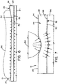
- FIG. 3 shows a top view of sensing device 32 of support pad 10 shown in FIG. 2 according to an embodiment of the present invention.
- FIG. 4 shows an enlarged view of a portion of sensing device 32 shown in FIG. 3 according to an embodiment of the present invention.
- Sensing device 32 is positioned between upper and middle cushion layers 28 and 34. A bottom surface 30 of upper cushion layer 28 and a top surface 36 of middle cushion layer 34 are in contact with sensing device 32.
- Sensing device 32 is generally comprised of a substrate 50, a plurality of sensing elements 52, at least one communication interface 54, and a plurality of conductive trace lines 99.
- substrate 50 is generally comprised of a plurality of row and column sections 97 and 100 on which conductive trace lines 99 are respectively formed, a plurality of tab portions 98 on which sensing elements 52 are respectively located, and openings 103 defined by row sections 97, column sections 100, and tab portions 98.
- Conductive trace lines 99 electrically connect sensing elements 52 with communication interfaces 54 located at the edge of sensing device 32.
- Each column section 100 includes at least one expandable portion 101 that is biased in a contracted position.
- Each expandable portion 101 is moveable between contracted and expanded positions and configured to expand in response to a load applied to upper cushion layer 28.
- Sections of conductive trace lines 99 that are respectively formed on expandable portions 101 expand and contract according to the expansion and contraction of expandable portions 101.
- each tab portion 98 has a fixed end 107 attached to a row section 97 and a free end 105 extending from the row section 97 into a corresponding opening 103.
- Each tab portion 98 is free to move and flex within the respective openings 103.
- sensing device 32 is arranged as a layer of layer assembly 26.
- sensing device 32 and substrate 50 may be implemented and will be apparent to those of ordinary skill in the art.
- substrate 50 serves to provide a matrix of sensing elements 52.
- the structure of substrate 50 and arrangements of sensing elements 52 located on substrate 50 are not limited thereto.
- row sections 97 it is conceivable for row sections 97 to include expandable portions 101 in place of or in addition to expandable portions 101 of column sections 100.
- substrate 50 is made of a flexible polymer sheet.
- suitable materials for substrate 50 include, but are not limited to, polyethylene terephthalate (PET), polyimide, and thermoplastic polyurethane.
- middle cushion layer 34 is positioned between sensing device 32 and controller unit 38.
- middle cushion layer 34 is a foam layer having a thickness in a range of about 2.54 cm (1.0 inch) to about 10.16 cm (4.0 inches) and a density in a range of about 40.04616 kg/m 3 (2.5 lbs/ft 3 ) to about 64.07385 kg/m 3 (4.0 lbs/ft 3 ).
- middle cushion layer 34 may be split into multiple cushion layers constructed of the same or different materials.
- middle cushion layer 34 may be formed of cushion materials as described above in connection with upper cushion layer 28, such as, but not limited to, soft core memory foam, gel-infused foam, and polyurethane foam.
- Controller unit 38 is positioned between middle cushion layer 34 and lower cushion layer 40.
- controller unit 38 is arranged as a layer of layer assembly 26.
- the arrangement of controller unit 38 is not limited thereto.
- controller unit 38 may be embedded in cushion material to protect controller unit 38 from damage.
- controller unit 38 may be located inside a housing unit.
- the cushion material embedding controller unit 38 may include, but is not limited to, closed cell foam, rubber, and those materials described above in connection with upper and middle cushion layers 28 and 34.
- cushion materials of controller unit 38 may take the form of a foam material having a thickness in a range of about 0.635 cm (0.25 inches) to about 1.27 cm (0.5 inches) and a density in the range of about 64.07385 kg/m 3 (4.0 lbs/ft 3 ) to about 320.3693 kg/m 3 (20.0 lbs/ft 3 ).
- respective layer assemblies (not shown) of support pads 8 and 12 generally correspond with layer assembly 26 of support pad 10.
- respective sensing devices 42 and 44 (see FIG. 5 ) of support pads 8 and 12 may be generally comprised of the same basic components as sensing device 32 of support pad 10.
- inventive concepts described in terms of support pad 10 apply equally to support pads 8 and 12. Therefore, detailed descriptions of support pads 8 and 12 are omitted.
- support pads 8 and 12 have different dimensions than support pad 10. In this respect, support pads 8 and 12 are respectively dimensioned to support head and leg/foot regions of the patient.
- FIG. 5 shows a monitoring system 120 according to an embodiment of the present invention.
- Monitoring system 120 is generally comprised of a data acquisition system 132, at least one wireless communication module 130, respective sensing devices 42, 32, and 44 of support pads 8, 10, and 12, and respective controller units 122, 38, and 126 of support pads 8, 10, and 12.
- controller units 122, 38, and 126 are respectively electrically connected to sensing devices 42, 32, and 44 via respective communication interfaces 56, 54, and 58. Controller units 122, 38, and 126 receive respective signals from sensing devices 42, 32, and 44 indicative of pressure data sensed by sensing elements 52. In the illustrated embodiment, controller units 122 and 126 are further configured to relay respective pressure data received from sensing devices 42 and 44 to controller unit 38. The connections between controller units 122, 38, and 126 may be wired or wireless connections.
- controller unit 38 aggregates the pressure data originally acquired by sensing devices 42, 32, and 44 and communicates with data acquisition system 132 via wireless communication module 130. Controller unit 38 sends the aggregated data to data acquisition system 132 for storage and display of the aggregated data. It will be appreciated that wireless communication module 130 uses wireless communication protocols well known to those skilled in the art.
- controller unit 38 serves as a master controller, while controller units 122 and 126 serve as slave controllers. In this respect, controller unit 38 communicates with controller units 122 and 126, and with data acquisition system 132.
- controller units 122, 38, and 126 may be implemented and will be apparent to those of ordinary skill in the art.
- controllers 122 and 126 may send data collected from respective sensing devices 42 and 44 directly to data acquisition system 132 via wired or wireless means.
- wireless communication module 130 may receive power through surgical table 2 or any number of means known to one having ordinary skill in the art.
- data acquisition system 132 is generally comprised of a processing unit 134, an input unit 136, a data storage unit 138, and a display unit 140.
- Processing unit 134 receives the aggregated data from controller unit 38 and processes the data for storage in data storage unit 138 and/or for display by display unit 140.
- Input unit 136 is used to request data from data storage unit 138 to be retrieved for processing by processing unit 134 and display by display unit 140.
- data acquisition system 132 may be implemented and will be apparent to those of ordinary skill in the art.
- data acquisition system 132 may be contained within a personal computing device or distributed over a plurality of computing devices in multiple locations.
- Data acquisition system 132 may advantageously employ any combination of computing devices, user inputs, displays, notification devices, storage servers, and networking components known to one having ordinary skill in the art.
- Input unit 136 may include, but is not limited to, a keyboard, a mouse controller, and a touch-screen.
- Display unit 140 may include, but is not limited to, a video display, a projector, and a printer. Devices corresponding with input unit 136 and display unit 140 are well known to the ordinary skilled artisan. It will be further appreciated that the processed data may be manifested in the form of pressure maps, pressure ulcer risk maps, graphs, or statistics, or any combination thereof.
- FIG. 6 shows a cross-sectional side view illustrating an example of support pad 10 according to an embodiment of the present invention to which a distributed load is applied.
- Patient 150 is illustrated in FIG. 6 as applying a load to support pad 10 that is distributed, i.e., generally uniform, across an area of support pad 10.
- a distributed load may be caused by areas of patient 150 that are positioned flat on support pad 10.
- an area of support pad 10 on which the distributed load is applied generally corresponds to an area of load redistribution within support pad 10.
- the load applied by patient 150 is generally distributed across top surface 20. It is assumed that cover 24 and upper cushion layer 28 provide good load transmission, thereby resulting in substantially direct transmission of the load through cover 24 and upper cushion layer 28 to sensing device 32. As a result, interface pressure sensed by sensing elements 52 is substantially equivalent to the load applied by patient 150 to support pad 10. Thus, pressure created by application of a distributed load of patient 150 to support pad 10 may be accurately measured by sensing device 32 with minimal or no increases in interface pressure.
- FIG. 7 shows a cross-sectional side view illustrating an example of support pad 10 according to an embodiment of the present invention to which an acute load is provided.
- Patient 150 is illustrated in FIG. 7 as applying a load to support pad 10 that is acute, i.e., generally concentrated in a small area of support pad 10.
- An acute load may be caused by bony prominences of patient 150 that are positioned on support pad 10. Examples of bony prominences include, but are not limited to, areas of a pelvis of patient 150 or a heel of patient 150.
- the illustrated bony prominence of patient 150 applies a load to the top surface 20 of support pad 10. It is assumed that cover 24 and upper cushion layer 28 provide good load redistribution, thereby resulting in substantially indirect transmission of certain portions of the load through cover 24 and upper cushion layer 28 to sensing device 32. Portions of the load applied by the bony prominence of patient 150 create tangential shear forces. These tangential shear forces are created by the bony prominence around an area of top surface 20 at which the bony prominence is supported. The created tangential shear forces are subsequently transmitted through cover 24 and upper cushion layer 28.
- Expandable portions 101, tab portions 98, and openings 103 allow substrate 50 to stretch in response to the concentrated load that is directly transmitted through cover 24 and upper cushion layer 28.
- substrate 50 has a reduced resistance to loads applied to top surface 20 of support pad 10.
- the substrate 50 is further able to transmit corresponding pressure from bottom surface 30 of upper cushion layer 28 to top surface 36 of middle cushion layer 34. This allows bottom surface 30 of upper cushion layer 28 and top surface 36 of middle cushion layer 34 to conform to the stretched substrate 50, thereby reducing interface pressure at top surface 20 of support pad 10.
- This also allows cover 24 and upper cushion layer 28 to envelope the bony prominence of patient 150.
- present invention is particularly applicable for sensing pressure from within support pad 10 and is described with reference thereto, it will be appreciated from a further reading of the present disclosure that the present invention finds advantageous application in sensing other parameters from within support pad 10, such as, but not limited to, temperature.
- temperature sensing elements could be used in place of pressure sensing elements 52 to sense a temperature of upper cushion layer 28.
- sensing accuracy of sensing device 32 may be achieved by other means in addition to the ability of substrate 50 to stretch.
- sensing accuracy of sensing device 32 may additionally be improved by minimizing the thickness of upper cushion layer 28, which may improve direct transmission of the loads to sensing device 32.
- sensing elements 52 positioned in support pad 10
- sensing elements 52 positioned in support pad 10
- these functions may include, but are not limited to, heating with heating elements positioned in support pad 10 and excitation with excitation elements positioned in support pad 10.
- pressure sensing elements 52 may be replaced with heating elements to heat support pad 10.
Landscapes
- Health & Medical Sciences (AREA)
- Life Sciences & Earth Sciences (AREA)
- Veterinary Medicine (AREA)
- Animal Behavior & Ethology (AREA)
- General Health & Medical Sciences (AREA)
- Public Health (AREA)
- Biomedical Technology (AREA)
- Engineering & Computer Science (AREA)
- Nursing (AREA)
- Dermatology (AREA)
- Physics & Mathematics (AREA)
- Biophysics (AREA)
- Pathology (AREA)
- Heart & Thoracic Surgery (AREA)
- Medical Informatics (AREA)
- Molecular Biology (AREA)
- Surgery (AREA)
- Force Measurement Appropriate To Specific Purposes (AREA)
Description
- The present invention relates generally to the field of patient support devices, and, more particularly, a support pad having embedded electronic components.
- A support pad is typically used to support a patient undergoing a surgical procedure. The patient positioned on the support pad applies a load to the support pad. At least a portion of the load is resisted by the support pad. The resistance of the support pad serves to create an interface pressure at the surface of the support pad on which the patient is positioned. The interface pressure is applied to the patient's tissues contacting the surface of the support pad. Pressure ulcers are more likely to develop in tissues that have been exposed to long periods of elevated interface pressure.
- An amount of interface pressure applied to the tissues is generally related to respective loads applied to the support pad and an ability of the support pad to redistribute loads over the surface of the support pad. For example, a rigid support pad may be less likely to effectively redistribute loads therein than a soft support pad due to an inability of a surface of the rigid support pad to envelop the loads. This is at least partially due to the tendency of rigid surfaces to resist an application of force thereto. Thus, a greater peak of interface pressure may be applied to the tissues by the rigid pad than the soft pad.
- Pressure sensing devices or other electronic components embedded in a support pad (e.g., temperature sensing, heating or excitation devices) are commonly positioned adjacent to an outer surface of the support pad. However, these electronic components are generally semi-rigid, thereby leading to increases in interface pressure and reduced load redistribution through the support pad.
US 9,333,136 B2 EP 2 394 623 A1 - The present invention provides a support pad with embedded electronic components that overcomes these and other drawbacks of the prior art.
- In accordance with the present invention, there is provided a support pad according to claim 1. The support pad includes a first cushion layer, a second cushion layer, and a sensing device. The sensing device is positioned between the first and second cushion layers. The sensing device includes a plurality of sensing elements and a substrate. The substrate includes a plurality of tab portions and a plurality of expandable portions. The sensing elements are respectively mounted to the tab portions. The expandable portions are moveable between contracted and expanded positions in response to pressure applied thereto.
- In accordance with another embodiment, there is provided a support pad. The support pad includes a first cushion layer, a second cushion layer, and an electronic device. The electronic device is positioned between the first and second cushion layers. The electronic device includes a plurality of electronic elements and a substrate. The substrate includes a plurality of tab portions and a plurality of expandable portions. The electronic elements are respectively mounted to the tab portions. The expandable portions are moveable between contracted and expanded positions in response to pressure applied thereto.
- In accordance with a further embodiment, there is provided a support pad assembly. The support pad assembly includes a first support pad. The first support pad includes a first cushion layer, a second cushion layer, and a sensing device. The sensing device is positioned between the first and second cushion layers. The sensing device includes a plurality of sensing elements and a substrate. The substrate includes a plurality of tab portions and a plurality of expandable portions. The sensing elements are respectively mounted to the tab portions. The expandable portions are moveable between contracted and expanded positions in response to pressure applied thereto.
- An advantage of the present invention is the provision of a support pad that enables improved redistribution of loads applied to the support pad.
- Another advantage of the present invention is the provision of a support pad including a sensing device that enables accurate sensing of interface pressure for both acute and distributed loads applied to tissues of a patient at a surface of the support pad.
- An additional advantage of the present invention is the provision of a support pad including a sensing device designed to reduce interface pressure generated at a surface of the support pad without causing an appreciable difference to interface pressure.
- A further advantage of the present invention is the provision of a support pad including electronic components located on a substrate that is flexible, strong, and compatible with printed electronic devices.
- These and other advantages will become apparent from the following description of a preferred embodiment taken together with the accompanying drawings and the appended claims.
- The invention may take physical form in certain parts and arrangement of parts, a preferred embodiment of which will be described in detail in the specification and illustrated in the accompanying drawings which form a part hereof, and wherein:
-
FIG. 1 is a perspective view illustrating a support pad assembly according to an embodiment of the present invention, wherein the support pad assembly is positioned on an example surgical table; -
FIG. 2 is a cross-sectional view of a support pad taken along lines 2-2 ofFIG. 1 according to an embodiment of the present invention; -
FIG. 3 is a top view of a sensing device of the support pad shown inFIG. 2 according to an embodiment of the present invention; -
FIG. 4 is an enlarged view of a portion of the sensing device shown inFIG. 3 according to an embodiment of the present invention; -
FIG. 5 is a schematic view of a monitoring system according to an embodiment of the present invention; -
FIG. 6 is a cross-sectional side view illustrating an example of a support pad according to an embodiment of the present invention to which a distributed load is applied; and -
FIG. 7 is a cross-sectional side view illustrating an example of a support pad according to an embodiment of the present invention to which an acute load is provided. - The present invention will now be described with reference to a support pad that includes a pressure sensing device. However, it will be appreciated that the support pad of the present disclosure may also include other electronic devices, including, but not limited to, temperature sensing, strain sensing, moisture sensing, ultraviolet energy sensing, heating, and excitation devices.
- Referring now to the drawings wherein the showings are for the purposes of illustrating embodiments of the invention only and not for the purposes of limiting same,
FIG. 1 shows asupport pad assembly 6 according to an embodiment of the present invention.Support pad assembly 6 is positioned on a support surface 4 of a surgical table 2 to support and cushion a patient that is situated thereon. - In the illustrated embodiment,
support pad assembly 6 is generally comprised ofsupport pads -
Support pad assembly 6 is generally comprised of one or more support pads according to patient positioning needs. Whilesupport pads support pads support pads support pads support pad assembly 6 is a single support pad sized to cover an entire area of support surface 4. -
FIG. 2 shows a cross-sectional view ofsupport pad 10 taken along lines 2-2 ofFIG. 1 according to an embodiment of the present invention.Support pad 10 is generally comprised of acover 24 and alayer assembly 26, both of which are radiolucent.Cover 24 surrounds andhouses layer assembly 26, and also defines top andbottom surfaces support pad 10. A patient is positioned ontop surface 20.Bottom surface 22 is positioned on a support surface, such as support surface 4.Cover 24 may be comprised of a soft and pliable polymer material that stretches in response to applied pressure, such as, but not limited to, vinyl-based materials. An example thickness ofsupport pad 10 is in a range of about 2.54 cm (1.0 inch) to about 12.7 cm (5.0 inches), but is not limited thereto. - In the illustrated embodiment,
layer assembly 26 is generally comprised of, from a bottom to a top thereof, alower cushion layer 40, acontroller unit 38, amiddle cushion layer 34, asensing device 32, and anupper cushion layer 28. -
Upper cushion layer 28 is located adjacent totop surface 20 ofsupport pad 10.Upper cushion layer 28 provides tactile isolation ofsensing device 32 fromtop surface 20 ofsupport pad 10. In the illustrated embodiment,upper cushion layer 28 is comprised of a foam material having a thickness in a range of about 0.3175 cm (0.125 inches) to about 1.905 cm (0.75 inches) and a density in a range of about 44.8517 kg/m3 (2.8 lbs/ft3) to about 80.09232 kg/m3 (5.0 lbs/ft3). Suitable types of foam material forupper cushion layer 28 include, but are not limited to, soft core memory foam, visco-elastic foam, gel-infused foam, slow-recovery foam, latex foam, or other flexible polyurethane foam material. Other suitable materials forupper cushion layer 28 include, but are not limited to, cotton, latex, and polyester. -
FIG. 3 shows a top view ofsensing device 32 ofsupport pad 10 shown inFIG. 2 according to an embodiment of the present invention.FIG. 4 shows an enlarged view of a portion ofsensing device 32 shown inFIG. 3 according to an embodiment of the present invention. -
Sensing device 32 is positioned between upper and middle cushion layers 28 and 34. Abottom surface 30 ofupper cushion layer 28 and atop surface 36 ofmiddle cushion layer 34 are in contact withsensing device 32.Sensing device 32 is generally comprised of asubstrate 50, a plurality ofsensing elements 52, at least onecommunication interface 54, and a plurality of conductive trace lines 99. -
Sensing elements 52 are configured to sense pressure applied by a load ontocover 24 and transmitted throughcover 24 andupper cushion layer 28. In the illustrated embodiment, eachsensing element 52 is a load-sensitive resistor sensing cell, or a sensel, but is not limited thereto. - As best seen in
FIG. 4 ,substrate 50 is generally comprised of a plurality of row andcolumn sections conductive trace lines 99 are respectively formed, a plurality oftab portions 98 on whichsensing elements 52 are respectively located, andopenings 103 defined byrow sections 97,column sections 100, andtab portions 98.Conductive trace lines 99 electrically connectsensing elements 52 withcommunication interfaces 54 located at the edge ofsensing device 32. - Each
column section 100 includes at least oneexpandable portion 101 that is biased in a contracted position. Eachexpandable portion 101 is moveable between contracted and expanded positions and configured to expand in response to a load applied toupper cushion layer 28. Sections ofconductive trace lines 99 that are respectively formed onexpandable portions 101 expand and contract according to the expansion and contraction ofexpandable portions 101. Further, eachtab portion 98 has a fixedend 107 attached to arow section 97 and afree end 105 extending from therow section 97 into acorresponding opening 103. Eachtab portion 98 is free to move and flex within therespective openings 103. - In the illustrated embodiment,
sensing device 32 is arranged as a layer oflayer assembly 26. However, it will be appreciated that other arrangements of the above-referenced elements ofsensing device 32 andsubstrate 50 may be implemented and will be apparent to those of ordinary skill in the art. - Further, in the illustrated embodiment,
substrate 50 serves to provide a matrix ofsensing elements 52. However, the structure ofsubstrate 50 and arrangements ofsensing elements 52 located onsubstrate 50 are not limited thereto. Additionally, it is conceivable forrow sections 97 to includeexpandable portions 101 in place of or in addition toexpandable portions 101 ofcolumn sections 100. Moreover, in the illustrated embodiment,substrate 50 is made of a flexible polymer sheet. Other suitable materials forsubstrate 50 include, but are not limited to, polyethylene terephthalate (PET), polyimide, and thermoplastic polyurethane. - Referring again to
FIG. 2 ,middle cushion layer 34 is positioned betweensensing device 32 andcontroller unit 38. In the illustrated embodiment,middle cushion layer 34 is a foam layer having a thickness in a range of about 2.54 cm (1.0 inch) to about 10.16 cm (4.0 inches) and a density in a range of about 40.04616 kg/m3 (2.5 lbs/ft3) to about 64.07385 kg/m3 (4.0 lbs/ft3). It will be appreciated thatmiddle cushion layer 34 may be split into multiple cushion layers constructed of the same or different materials. For example,middle cushion layer 34 may be formed of cushion materials as described above in connection withupper cushion layer 28, such as, but not limited to, soft core memory foam, gel-infused foam, and polyurethane foam. -
Controller unit 38 is positioned betweenmiddle cushion layer 34 andlower cushion layer 40. In the illustrated embodiment,controller unit 38 is arranged as a layer oflayer assembly 26. However, the arrangement ofcontroller unit 38 is not limited thereto. Further,controller unit 38 may be embedded in cushion material to protectcontroller unit 38 from damage. In addition, it is contemplated thatcontroller unit 38 may be located inside a housing unit. - The cushion material embedding
controller unit 38 may include, but is not limited to, closed cell foam, rubber, and those materials described above in connection with upper and middle cushion layers 28 and 34. For example, such cushion materials ofcontroller unit 38 may take the form of a foam material having a thickness in a range of about 0.635 cm (0.25 inches) to about 1.27 cm (0.5 inches) and a density in the range of about 64.07385 kg/m3 (4.0 lbs/ft3) to about 320.3693 kg/m3 (20.0 lbs/ft3). -
Lower cushion layer 40 is located adjacent tobottom surface 22 ofsupport pad 10. In the illustrated embodiment,lower cushion layer 40 is comprised of a foam material having a thickness in a range of about 0.3175 cm (0.125 inches) to about 0.9525 cm (0.375 inches) and a density in a range of about 24.0277 kg/m3 (1.5 lbs/ft3) to about 40.04616 kg/m3 (2.5 lbs/ft3). The foam material may take the form of a closed cell rubber material. However,lower cushion layer 40 may alternatively be formed of cushion materials as described above in connection withupper cushion layer 28. - It is noted that respective layer assemblies (not shown) of
support pads layer assembly 26 ofsupport pad 10. Moreover,respective sensing devices 42 and 44 (seeFIG. 5 ) ofsupport pads device 32 ofsupport pad 10. In addition, it will be appreciated that the inventive concepts described in terms ofsupport pad 10 apply equally to supportpads support pads - However, in the illustrated embodiment,
support pads support pad 10. In this respect,support pads -
FIG. 5 shows amonitoring system 120 according to an embodiment of the present invention.Monitoring system 120 is generally comprised of adata acquisition system 132, at least one wireless communication module 130,respective sensing devices support pads respective controller units support pads - In the illustrated embodiment,
controller units devices Controller units devices elements 52. In the illustrated embodiment,controller units 122 and 126 are further configured to relay respective pressure data received from sensingdevices controller unit 38. The connections betweencontroller units - In the illustrated embodiment,
controller unit 38 aggregates the pressure data originally acquired by sensingdevices data acquisition system 132 via wireless communication module 130.Controller unit 38 sends the aggregated data todata acquisition system 132 for storage and display of the aggregated data. It will be appreciated that wireless communication module 130 uses wireless communication protocols well known to those skilled in the art. - In the illustrated embodiment,
controller unit 38 serves as a master controller, whilecontroller units 122 and 126 serve as slave controllers. In this respect,controller unit 38 communicates withcontroller units 122 and 126, and withdata acquisition system 132. However, the embodiments described herein are not limited thereto. Further, it will also be appreciated that other suitable arrangements forcontroller units controllers 122 and 126 may send data collected fromrespective sensing devices data acquisition system 132 via wired or wireless means. - In addition, wireless communication module 130,
respective sensing devices support pads respective controller units support pads - In the illustrated embodiment,
data acquisition system 132 is generally comprised of aprocessing unit 134, aninput unit 136, adata storage unit 138, and adisplay unit 140.Processing unit 134 receives the aggregated data fromcontroller unit 38 and processes the data for storage indata storage unit 138 and/or for display bydisplay unit 140.Input unit 136 is used to request data fromdata storage unit 138 to be retrieved for processing byprocessing unit 134 and display bydisplay unit 140. - Manifestations of
data acquisition system 132 may be implemented and will be apparent to those of ordinary skill in the art. For example, it will be readily appreciated thatdata acquisition system 132 may be contained within a personal computing device or distributed over a plurality of computing devices in multiple locations. -
Data acquisition system 132 may advantageously employ any combination of computing devices, user inputs, displays, notification devices, storage servers, and networking components known to one having ordinary skill in the art.Input unit 136 may include, but is not limited to, a keyboard, a mouse controller, and a touch-screen.Display unit 140 may include, but is not limited to, a video display, a projector, and a printer. Devices corresponding withinput unit 136 anddisplay unit 140 are well known to the ordinary skilled artisan. It will be further appreciated that the processed data may be manifested in the form of pressure maps, pressure ulcer risk maps, graphs, or statistics, or any combination thereof. -
FIG. 6 shows a cross-sectional side view illustrating an example ofsupport pad 10 according to an embodiment of the present invention to which a distributed load is applied.Patient 150 is illustrated inFIG. 6 as applying a load to supportpad 10 that is distributed, i.e., generally uniform, across an area ofsupport pad 10. It is noted that, for the purposes of this discussion, a distributed load may be caused by areas ofpatient 150 that are positioned flat onsupport pad 10. In the illustrated embodiment, an area ofsupport pad 10 on which the distributed load is applied generally corresponds to an area of load redistribution withinsupport pad 10. - In
FIG. 6 , the load applied bypatient 150 is generally distributed acrosstop surface 20. It is assumed thatcover 24 andupper cushion layer 28 provide good load transmission, thereby resulting in substantially direct transmission of the load throughcover 24 andupper cushion layer 28 tosensing device 32. As a result, interface pressure sensed by sensingelements 52 is substantially equivalent to the load applied bypatient 150 to supportpad 10. Thus, pressure created by application of a distributed load ofpatient 150 to supportpad 10 may be accurately measured by sensingdevice 32 with minimal or no increases in interface pressure. -
FIG. 7 shows a cross-sectional side view illustrating an example ofsupport pad 10 according to an embodiment of the present invention to which an acute load is provided.Patient 150 is illustrated inFIG. 7 as applying a load to supportpad 10 that is acute, i.e., generally concentrated in a small area ofsupport pad 10. An acute load may be caused by bony prominences ofpatient 150 that are positioned onsupport pad 10. Examples of bony prominences include, but are not limited to, areas of a pelvis ofpatient 150 or a heel ofpatient 150. - In
FIG. 7 , the illustrated bony prominence ofpatient 150 applies a load to thetop surface 20 ofsupport pad 10. It is assumed thatcover 24 andupper cushion layer 28 provide good load redistribution, thereby resulting in substantially indirect transmission of certain portions of the load throughcover 24 andupper cushion layer 28 tosensing device 32. Portions of the load applied by the bony prominence ofpatient 150 create tangential shear forces. These tangential shear forces are created by the bony prominence around an area oftop surface 20 at which the bony prominence is supported. The created tangential shear forces are subsequently transmitted throughcover 24 andupper cushion layer 28. -
Expandable portions 101,tab portions 98, andopenings 103 allowsubstrate 50 to stretch in response to the concentrated load that is directly transmitted throughcover 24 andupper cushion layer 28. Thus,substrate 50 has a reduced resistance to loads applied totop surface 20 ofsupport pad 10. Thesubstrate 50 is further able to transmit corresponding pressure frombottom surface 30 ofupper cushion layer 28 totop surface 36 ofmiddle cushion layer 34. This allowsbottom surface 30 ofupper cushion layer 28 andtop surface 36 ofmiddle cushion layer 34 to conform to the stretchedsubstrate 50, thereby reducing interface pressure attop surface 20 ofsupport pad 10. This also allowscover 24 andupper cushion layer 28 to envelope the bony prominence ofpatient 150. - As
substrate 50 is stretched in accordance with the load applied by the bony prominence, the tangential shear forces created by the bony prominence are transmitted throughcover 24 andupper cushion layer 28 in directions that are increasingly more normal and direct tosensing device 32. As a result, load exposure to corresponding areas ofsensing device 32 is increased and sensing accuracy ofsensing device 32 is improved. Further, the resistance ofsubstrate 50 to pressure is reduced. As a result, increases in the interface pressure attop surface 20 ofsupport pad 10 are minimized or avoided. - While the present invention is particularly applicable for sensing pressure from within
support pad 10 and is described with reference thereto, it will be appreciated from a further reading of the present disclosure that the present invention finds advantageous application in sensing other parameters from withinsupport pad 10, such as, but not limited to, temperature. For example, temperature sensing elements could be used in place ofpressure sensing elements 52 to sense a temperature ofupper cushion layer 28. - Further, improved sensing accuracy of
sensing device 32 may be achieved by other means in addition to the ability ofsubstrate 50 to stretch. For example, sensing accuracy ofsensing device 32 may additionally be improved by minimizing the thickness ofupper cushion layer 28, which may improve direct transmission of the loads to sensingdevice 32. - In addition, while the present disclosure is particularly applicable for sensing with
sensing elements 52 positioned insupport pad 10, it will be appreciated from a further reading of the present disclosure that it finds advantageous application in providing other functions with electronic elements positioned insupport pad 10. These functions may include, but are not limited to, heating with heating elements positioned insupport pad 10 and excitation with excitation elements positioned insupport pad 10. For example,pressure sensing elements 52 may be replaced with heating elements to heatsupport pad 10. - The foregoing description provides example embodiments of the present invention. It should be appreciated that these embodiments are described for purposes of illustration only, and that numerous alterations and modifications may be practiced by those skilled in the art within the scope of the invention as claimed.
Claims (13)
- A support pad (10), comprising:a first cushion layer (28);a second cushion layer (34); anda sensing device (32) positioned between the first and second cushion layers (28, 34), the sensing device (32) comprising:a plurality of sensing elements (52); anda substrate (50) including:a plurality of row and column sections (97, 100), each of the column sections (100) comprising one or more expandable portions (101) biased in a contracted position, each expandable portion (101) being configured to move between the contracted position and an expanded position in response to pressure being applied thereto;a plurality of tab portions (98), said sensing elements (52) being respectively located on the tab portions (98); anda plurality of openings (103) defined by the row sections (97), the column sections (100), and the tab portions (98), said tab portions (98) being moveable within said openings (103),wherein each of said tab portions (98) has a fixed end (107) attached to one of the row sections (97) and a free end (105) extending from the one of the row sections (97) into a corresponding one of the openings (103).
- The support pad (10) of claim 1, wherein the substrate (50) further comprises a plurality of conductive trace lines (99) formed on the row and column sections (97, 100) for electrically connecting the sensing elements (52).
- The support pad (10) of claim 1, wherein the conductive trace lines (99) are formed on the expandable portions (101) and moveable in accordance with the expandable portions (101).
- The support pad (10) of claim 1, wherein said first cushion layer (28) is comprised of a foam material.
- The support pad (10) of claim 1, wherein said second cushion layer (34) is comprised of a foam material.
- The support pad (10) of claim 1,
wherein at least one of said row sections (97) includes one of said expandable portions (101). - The support pad (10) of claim 1, wherein the pressure applied to the expandable portions (101) is created by a load applied to the first cushion layer (28),
wherein, said sensing elements (52) sense the pressure created by the load applied to the first cushion layer (28), and
wherein the load applied to the first cushion layer (28) is transmitted through the first cushion layer (28) to the sensing elements (52). - The support pad (10) of claim 7, wherein the expandable portions (101) expand in response to the load applied to the first cushion layer (28).
- The support pad (10) of claim 7, wherein the tab portions (98) move in response to the load applied to the first cushion layer (28).
- The support pad (10) of claim 1, further comprising a cover (24) that surrounds the first cushion layer (28), the second cushion layer (34), and the sensing device (32).
- The support pad (10) of claim 1, further comprising a controller unit (38) and a third cushion layer (40), said controller unit (38) being located between the second and third cushion layers (34, 40).
- The support pad (10) of claim 11, wherein the sensing elements (52) are configured to sense the pressure applied to the expandable portions (101), and
wherein said controller unit (38) is electrically connected with the sensing device (32) to receive signals from the sensing device (32) indicative of the pressure sensed by the sensing elements (52). - The support pad (10) of claim 1, wherein the pressure applied to the expandable portions (101) is applied by a bottom surface (30) of the first cushion layer (28), and
wherein the substrate (50) is configured to transmit the pressure applied to the expandable portions (101) by the bottom surface (30) of the first cushion layer (28) to a top surface (36) of the second cushion layer (34).
Applications Claiming Priority (2)
| Application Number | Priority Date | Filing Date | Title |
|---|---|---|---|
| US15/159,866 US10314528B2 (en) | 2016-05-20 | 2016-05-20 | Patient support pad |
| PCT/US2017/031648 WO2017200794A1 (en) | 2016-05-20 | 2017-05-09 | Patient support pad |
Publications (3)
| Publication Number | Publication Date |
|---|---|
| EP3458010A1 EP3458010A1 (en) | 2019-03-27 |
| EP3458010A4 EP3458010A4 (en) | 2020-01-08 |
| EP3458010B1 true EP3458010B1 (en) | 2021-02-24 |
Family
ID=60325523
Family Applications (1)
| Application Number | Title | Priority Date | Filing Date |
|---|---|---|---|
| EP17799882.0A Active EP3458010B1 (en) | 2016-05-20 | 2017-05-09 | Patient support pad |
Country Status (6)
| Country | Link |
|---|---|
| US (2) | US10314528B2 (en) |
| EP (1) | EP3458010B1 (en) |
| AU (1) | AU2017268106B2 (en) |
| CA (1) | CA3020451C (en) |
| ES (1) | ES2865426T3 (en) |
| WO (1) | WO2017200794A1 (en) |
Families Citing this family (8)
| Publication number | Priority date | Publication date | Assignee | Title |
|---|---|---|---|---|
| US10314528B2 (en) * | 2016-05-20 | 2019-06-11 | American Sterilizer Company | Patient support pad |
| US10887747B2 (en) | 2018-04-20 | 2021-01-05 | Whelen Engineering Company, Inc. | Systems and methods for remote management of emergency equipment and personnel |
| US10657821B2 (en) | 2018-06-13 | 2020-05-19 | Whelen Engineering Company, Inc. | Autonomous intersection warning system for connected vehicles |
| US12177734B2 (en) | 2019-01-09 | 2024-12-24 | Whelen Engineering Company, Inc. | System and method for velocity-based geofencing for emergency vehicle |
| US10706722B1 (en) | 2019-03-06 | 2020-07-07 | Whelen Engineering Company, Inc. | System and method for map-based geofencing for emergency vehicle |
| US10531224B1 (en) | 2019-03-11 | 2020-01-07 | Whelen Engineering Company, Inc. | System and method for managing emergency vehicle alert geofence |
| US11758354B2 (en) | 2019-10-15 | 2023-09-12 | Whelen Engineering Company, Inc. | System and method for intent-based geofencing for emergency vehicle |
| US20220179293A1 (en) | 2020-12-03 | 2022-06-09 | Adasky, Ltd. | Lens clearing arrangement |
Family Cites Families (35)
| Publication number | Priority date | Publication date | Assignee | Title |
|---|---|---|---|---|
| US4584625A (en) * | 1984-09-11 | 1986-04-22 | Kellogg Nelson R | Capacitive tactile sensor |
| US5253656A (en) * | 1991-05-23 | 1993-10-19 | Rincoe Richard G | Apparatus and method for monitoring contact pressure between body parts and contact surfaces |
| US5571973A (en) * | 1994-06-06 | 1996-11-05 | Taylot; Geoffrey L. | Multi-directional piezoresistive shear and normal force sensors for hospital mattresses and seat cushions |
| US5606136A (en) * | 1995-04-10 | 1997-02-25 | Breed Automotive Technology, Inc. | Electrical lead crossover, sensing cell with electrical lead crossover, and method for making same |
| US6109117A (en) * | 1996-12-19 | 2000-08-29 | Automotive Systems Laboratory, Inc. | Seat weight sensor |
| US6386051B1 (en) * | 1999-03-15 | 2002-05-14 | Denso Corporation | Load detection sensor unit for bedding with single output line |
| LU90771B1 (en) * | 2001-05-08 | 2002-11-11 | Iee Sarl | Automotive seat detection device |
| AU2003212632A1 (en) * | 2002-03-25 | 2003-10-08 | Ramot At Tel Aviv University Ltd. | Method and system for determining a risk of ulcer onset |
| US7043997B2 (en) * | 2003-07-09 | 2006-05-16 | Cherry Corporation | Seat for sensing a load |
| US20050076715A1 (en) * | 2003-10-13 | 2005-04-14 | Kuklis Matthew M. | Shear sensor apparatus |
| US7201063B2 (en) * | 2004-04-30 | 2007-04-10 | Taylor Geoffrey L | Normal force gradient/shear force sensors and method of measuring internal biological tissue stress |
| US7469437B2 (en) | 2005-06-24 | 2008-12-30 | Tempur-Pedic Management, Inc. | Reticulated material body support and method |
| FR2920535B1 (en) * | 2007-08-30 | 2009-11-27 | Hill Rom Ind Sa | PRESSURE DETECTION AND MEASURING SENSOR INCORPORATING AT LEAST ONE RESISTIVE FORCE DETECTION CELL |
| WO2009038964A1 (en) * | 2007-09-19 | 2009-03-26 | Persimmon Scientific | Devices for prevention of pressure ulcers |
| US8161826B1 (en) | 2009-03-05 | 2012-04-24 | Stryker Corporation | Elastically stretchable fabric force sensor arrays and methods of making |
| US11278237B2 (en) * | 2010-04-22 | 2022-03-22 | Leaf Healthcare, Inc. | Devices, systems, and methods for preventing, detecting, and treating pressure-induced ischemia, pressure ulcers, and other conditions |
| US10729357B2 (en) * | 2010-04-22 | 2020-08-04 | Leaf Healthcare, Inc. | Systems and methods for generating and/or adjusting a repositioning schedule for a person |
| US8332975B2 (en) | 2009-08-31 | 2012-12-18 | Gentherm Incorporated | Climate-controlled topper member for medical beds |
| CA2786917A1 (en) | 2010-01-27 | 2011-08-04 | Robert Miller | Risk modeling for pressure ulcer formation |
| WO2011092970A1 (en) * | 2010-01-27 | 2011-08-04 | 東海ゴム工業株式会社 | Body position/body pressure control device |
| WO2012054781A1 (en) * | 2010-10-20 | 2012-04-26 | Tactus Technology | User interface system and method |
| EP2685954A4 (en) * | 2011-03-16 | 2015-07-01 | Augustine Temperature Man Llc | Heated under-body warming system |
| US20130213147A1 (en) * | 2012-02-22 | 2013-08-22 | Nike, Inc. | Footwear Having Sensor System |
| US9757303B2 (en) * | 2012-04-27 | 2017-09-12 | John Marinkovic | Therapeutic pillow |
| US20140059778A1 (en) * | 2012-08-30 | 2014-03-06 | Ronald B. Jalbert | Interface pressure sensing mattress |
| GB201219632D0 (en) * | 2012-10-31 | 2012-12-12 | Univ Southampton | Apparatus for sensing and measuring pressure and shear components of a force at an interface between two surfaces |
| US20140243709A1 (en) * | 2013-02-28 | 2014-08-28 | Hill-Rom Services, Inc. | Pressure Sensing Pad, Method of Making the Same, Pressure Sensing System, and Pressure Map Display |
| US9333136B2 (en) * | 2013-02-28 | 2016-05-10 | Hill-Rom Services, Inc. | Sensors in a mattress cover |
| US9778131B2 (en) * | 2013-05-21 | 2017-10-03 | Orpyx Medical Technologies Inc. | Pressure data acquisition assembly |
| WO2016125904A1 (en) * | 2015-02-05 | 2016-08-11 | 三井化学株式会社 | Sensor-equipped cushion material, and bed |
| GB2535229B (en) * | 2015-02-13 | 2017-11-29 | Jensen Gemma | Neck support pillow |
| US10416031B2 (en) * | 2015-09-25 | 2019-09-17 | MedicusTek, Inc. | Pressure sensing device |
| US10194856B2 (en) * | 2015-12-22 | 2019-02-05 | Sharp Laboratories Of America, Inc. | Matrix multi-sensor array |
| US9949683B2 (en) * | 2015-12-22 | 2018-04-24 | Sharp Laboratories Of America, Inc. | Dual-function active matrix sensor array |
| US10314528B2 (en) * | 2016-05-20 | 2019-06-11 | American Sterilizer Company | Patient support pad |
-
2016
- 2016-05-20 US US15/159,866 patent/US10314528B2/en active Active
-
2017
- 2017-05-09 CA CA3020451A patent/CA3020451C/en active Active
- 2017-05-09 AU AU2017268106A patent/AU2017268106B2/en active Active
- 2017-05-09 WO PCT/US2017/031648 patent/WO2017200794A1/en not_active Ceased
- 2017-05-09 ES ES17799882T patent/ES2865426T3/en active Active
- 2017-05-09 EP EP17799882.0A patent/EP3458010B1/en active Active
-
2019
- 2019-02-14 US US16/275,657 patent/US10582888B2/en active Active
Non-Patent Citations (1)
| Title |
|---|
| None * |
Also Published As
| Publication number | Publication date |
|---|---|
| ES2865426T3 (en) | 2021-10-15 |
| US20170332803A1 (en) | 2017-11-23 |
| US10582888B2 (en) | 2020-03-10 |
| CA3020451A1 (en) | 2017-11-23 |
| EP3458010A4 (en) | 2020-01-08 |
| US10314528B2 (en) | 2019-06-11 |
| AU2017268106A1 (en) | 2018-11-01 |
| AU2017268106B2 (en) | 2019-05-02 |
| WO2017200794A1 (en) | 2017-11-23 |
| CA3020451C (en) | 2021-01-05 |
| US20190175099A1 (en) | 2019-06-13 |
| EP3458010A1 (en) | 2019-03-27 |
Similar Documents
| Publication | Publication Date | Title |
|---|---|---|
| US10582888B2 (en) | Patient support pad | |
| US20250170004A1 (en) | Inflatable mattress and control methods | |
| EP2394623B1 (en) | Body position/body pressure control device | |
| EP2772238B1 (en) | Sensors in a mattress cover | |
| US8528135B2 (en) | Systems for relieving pressure sores and methods therefor | |
| EP2685954A2 (en) | Heated under-body warming system | |
| US12097155B2 (en) | Mattress, sensor system | |
| JP2001238924A (en) | Mattress for operating table | |
| US20130167301A1 (en) | Air cushion bed with sensing mat capable of detecting the lying of a patient thereon | |
| JP2025100776A (en) | Judgment device | |
| KR102903761B1 (en) | Bedsore prevention bed | |
| JP7504671B2 (en) | Air cell control device | |
| JP2021052867A (en) | Fluid cell type mattress | |
| KR102439520B1 (en) | Bed mattress for preventing bedsores and manufacturing and operating method thereof | |
| WO2025080514A1 (en) | Inflatable mattress and control thereof | |
| CN121240845A (en) | Integrated pressure sensing and redistribution of the control panel mattress | |
| AU2024277386A1 (en) | Inflatable mattress and control thereof | |
| EP2614806A1 (en) | Air cushion bed with sensing mat capable of detecting the lying of a patient thereon | |
| WO2025185779A1 (en) | A mattress having an automatic pressure adjustment | |
| CN115326253A (en) | Array type point location pressure monitoring and regulating device |
Legal Events
| Date | Code | Title | Description |
|---|---|---|---|
| STAA | Information on the status of an ep patent application or granted ep patent |
Free format text: STATUS: THE INTERNATIONAL PUBLICATION HAS BEEN MADE |
|
| PUAI | Public reference made under article 153(3) epc to a published international application that has entered the european phase |
Free format text: ORIGINAL CODE: 0009012 |
|
| STAA | Information on the status of an ep patent application or granted ep patent |
Free format text: STATUS: REQUEST FOR EXAMINATION WAS MADE |
|
| 17P | Request for examination filed |
Effective date: 20181023 |
|
| AK | Designated contracting states |
Kind code of ref document: A1 Designated state(s): AL AT BE BG CH CY CZ DE DK EE ES FI FR GB GR HR HU IE IS IT LI LT LU LV MC MK MT NL NO PL PT RO RS SE SI SK SM TR |
|
| AX | Request for extension of the european patent |
Extension state: BA ME |
|
| DAV | Request for validation of the european patent (deleted) | ||
| DAX | Request for extension of the european patent (deleted) | ||
| A4 | Supplementary search report drawn up and despatched |
Effective date: 20191210 |
|
| RIC1 | Information provided on ipc code assigned before grant |
Ipc: A61G 13/12 20060101ALI20191204BHEP Ipc: A61G 7/05 20060101ALN20191204BHEP Ipc: A61G 7/057 20060101AFI20191204BHEP |
|
| RIC1 | Information provided on ipc code assigned before grant |
Ipc: A61G 7/057 20060101ALN20200724BHEP Ipc: A61G 13/12 20060101AFI20200724BHEP Ipc: A61G 13/10 20060101ALI20200724BHEP |
|
| REG | Reference to a national code |
Ref country code: DE Ref legal event code: R079 Ref document number: 602017033415 Country of ref document: DE Free format text: PREVIOUS MAIN CLASS: A61G0007050000 Ipc: A61G0013120000 |
|
| GRAP | Despatch of communication of intention to grant a patent |
Free format text: ORIGINAL CODE: EPIDOSNIGR1 |
|
| STAA | Information on the status of an ep patent application or granted ep patent |
Free format text: STATUS: GRANT OF PATENT IS INTENDED |
|
| RIC1 | Information provided on ipc code assigned before grant |
Ipc: A61G 13/12 20060101AFI20200909BHEP Ipc: A61G 13/10 20060101ALI20200909BHEP Ipc: A61G 7/057 20060101ALN20200909BHEP |
|
| INTG | Intention to grant announced |
Effective date: 20200921 |
|
| GRAS | Grant fee paid |
Free format text: ORIGINAL CODE: EPIDOSNIGR3 |
|
| GRAA | (expected) grant |
Free format text: ORIGINAL CODE: 0009210 |
|
| STAA | Information on the status of an ep patent application or granted ep patent |
Free format text: STATUS: THE PATENT HAS BEEN GRANTED |
|
| AK | Designated contracting states |
Kind code of ref document: B1 Designated state(s): AL AT BE BG CH CY CZ DE DK EE ES FI FR GB GR HR HU IE IS IT LI LT LU LV MC MK MT NL NO PL PT RO RS SE SI SK SM TR |
|
| REG | Reference to a national code |
Ref country code: CH Ref legal event code: EP |
|
| REG | Reference to a national code |
Ref country code: AT Ref legal event code: REF Ref document number: 1363571 Country of ref document: AT Kind code of ref document: T Effective date: 20210315 |
|
| REG | Reference to a national code |
Ref country code: IE Ref legal event code: FG4D |
|
| REG | Reference to a national code |
Ref country code: DE Ref legal event code: R096 Ref document number: 602017033415 Country of ref document: DE |
|
| REG | Reference to a national code |
Ref country code: LT Ref legal event code: MG9D |
|
| REG | Reference to a national code |
Ref country code: NL Ref legal event code: MP Effective date: 20210224 |
|
| PG25 | Lapsed in a contracting state [announced via postgrant information from national office to epo] |
Ref country code: FI Free format text: LAPSE BECAUSE OF FAILURE TO SUBMIT A TRANSLATION OF THE DESCRIPTION OR TO PAY THE FEE WITHIN THE PRESCRIBED TIME-LIMIT Effective date: 20210224 Ref country code: GR Free format text: LAPSE BECAUSE OF FAILURE TO SUBMIT A TRANSLATION OF THE DESCRIPTION OR TO PAY THE FEE WITHIN THE PRESCRIBED TIME-LIMIT Effective date: 20210525 Ref country code: HR Free format text: LAPSE BECAUSE OF FAILURE TO SUBMIT A TRANSLATION OF THE DESCRIPTION OR TO PAY THE FEE WITHIN THE PRESCRIBED TIME-LIMIT Effective date: 20210224 Ref country code: NO Free format text: LAPSE BECAUSE OF FAILURE TO SUBMIT A TRANSLATION OF THE DESCRIPTION OR TO PAY THE FEE WITHIN THE PRESCRIBED TIME-LIMIT Effective date: 20210524 Ref country code: PT Free format text: LAPSE BECAUSE OF FAILURE TO SUBMIT A TRANSLATION OF THE DESCRIPTION OR TO PAY THE FEE WITHIN THE PRESCRIBED TIME-LIMIT Effective date: 20210624 Ref country code: BG Free format text: LAPSE BECAUSE OF FAILURE TO SUBMIT A TRANSLATION OF THE DESCRIPTION OR TO PAY THE FEE WITHIN THE PRESCRIBED TIME-LIMIT Effective date: 20210524 Ref country code: LT Free format text: LAPSE BECAUSE OF FAILURE TO SUBMIT A TRANSLATION OF THE DESCRIPTION OR TO PAY THE FEE WITHIN THE PRESCRIBED TIME-LIMIT Effective date: 20210224 |
|
| REG | Reference to a national code |
Ref country code: AT Ref legal event code: MK05 Ref document number: 1363571 Country of ref document: AT Kind code of ref document: T Effective date: 20210224 |
|
| PG25 | Lapsed in a contracting state [announced via postgrant information from national office to epo] |
Ref country code: RS Free format text: LAPSE BECAUSE OF FAILURE TO SUBMIT A TRANSLATION OF THE DESCRIPTION OR TO PAY THE FEE WITHIN THE PRESCRIBED TIME-LIMIT Effective date: 20210224 Ref country code: LV Free format text: LAPSE BECAUSE OF FAILURE TO SUBMIT A TRANSLATION OF THE DESCRIPTION OR TO PAY THE FEE WITHIN THE PRESCRIBED TIME-LIMIT Effective date: 20210224 Ref country code: NL Free format text: LAPSE BECAUSE OF FAILURE TO SUBMIT A TRANSLATION OF THE DESCRIPTION OR TO PAY THE FEE WITHIN THE PRESCRIBED TIME-LIMIT Effective date: 20210224 Ref country code: PL Free format text: LAPSE BECAUSE OF FAILURE TO SUBMIT A TRANSLATION OF THE DESCRIPTION OR TO PAY THE FEE WITHIN THE PRESCRIBED TIME-LIMIT Effective date: 20210224 Ref country code: SE Free format text: LAPSE BECAUSE OF FAILURE TO SUBMIT A TRANSLATION OF THE DESCRIPTION OR TO PAY THE FEE WITHIN THE PRESCRIBED TIME-LIMIT Effective date: 20210224 |
|
| PG25 | Lapsed in a contracting state [announced via postgrant information from national office to epo] |
Ref country code: IS Free format text: LAPSE BECAUSE OF FAILURE TO SUBMIT A TRANSLATION OF THE DESCRIPTION OR TO PAY THE FEE WITHIN THE PRESCRIBED TIME-LIMIT Effective date: 20210624 |
|
| REG | Reference to a national code |
Ref country code: ES Ref legal event code: FG2A Ref document number: 2865426 Country of ref document: ES Kind code of ref document: T3 Effective date: 20211015 |
|
| PG25 | Lapsed in a contracting state [announced via postgrant information from national office to epo] |
Ref country code: EE Free format text: LAPSE BECAUSE OF FAILURE TO SUBMIT A TRANSLATION OF THE DESCRIPTION OR TO PAY THE FEE WITHIN THE PRESCRIBED TIME-LIMIT Effective date: 20210224 Ref country code: CZ Free format text: LAPSE BECAUSE OF FAILURE TO SUBMIT A TRANSLATION OF THE DESCRIPTION OR TO PAY THE FEE WITHIN THE PRESCRIBED TIME-LIMIT Effective date: 20210224 Ref country code: SM Free format text: LAPSE BECAUSE OF FAILURE TO SUBMIT A TRANSLATION OF THE DESCRIPTION OR TO PAY THE FEE WITHIN THE PRESCRIBED TIME-LIMIT Effective date: 20210224 Ref country code: AT Free format text: LAPSE BECAUSE OF FAILURE TO SUBMIT A TRANSLATION OF THE DESCRIPTION OR TO PAY THE FEE WITHIN THE PRESCRIBED TIME-LIMIT Effective date: 20210224 |
|
| REG | Reference to a national code |
Ref country code: DE Ref legal event code: R097 Ref document number: 602017033415 Country of ref document: DE |
|
| PG25 | Lapsed in a contracting state [announced via postgrant information from national office to epo] |
Ref country code: SK Free format text: LAPSE BECAUSE OF FAILURE TO SUBMIT A TRANSLATION OF THE DESCRIPTION OR TO PAY THE FEE WITHIN THE PRESCRIBED TIME-LIMIT Effective date: 20210224 Ref country code: DK Free format text: LAPSE BECAUSE OF FAILURE TO SUBMIT A TRANSLATION OF THE DESCRIPTION OR TO PAY THE FEE WITHIN THE PRESCRIBED TIME-LIMIT Effective date: 20210224 Ref country code: RO Free format text: LAPSE BECAUSE OF FAILURE TO SUBMIT A TRANSLATION OF THE DESCRIPTION OR TO PAY THE FEE WITHIN THE PRESCRIBED TIME-LIMIT Effective date: 20210224 |
|
| REG | Reference to a national code |
Ref country code: CH Ref legal event code: PL |
|
| PLBE | No opposition filed within time limit |
Free format text: ORIGINAL CODE: 0009261 |
|
| STAA | Information on the status of an ep patent application or granted ep patent |
Free format text: STATUS: NO OPPOSITION FILED WITHIN TIME LIMIT |
|
| PG25 | Lapsed in a contracting state [announced via postgrant information from national office to epo] |
Ref country code: LU Free format text: LAPSE BECAUSE OF NON-PAYMENT OF DUE FEES Effective date: 20210509 Ref country code: MC Free format text: LAPSE BECAUSE OF FAILURE TO SUBMIT A TRANSLATION OF THE DESCRIPTION OR TO PAY THE FEE WITHIN THE PRESCRIBED TIME-LIMIT Effective date: 20210224 Ref country code: CH Free format text: LAPSE BECAUSE OF NON-PAYMENT OF DUE FEES Effective date: 20210531 Ref country code: AL Free format text: LAPSE BECAUSE OF FAILURE TO SUBMIT A TRANSLATION OF THE DESCRIPTION OR TO PAY THE FEE WITHIN THE PRESCRIBED TIME-LIMIT Effective date: 20210224 Ref country code: LI Free format text: LAPSE BECAUSE OF NON-PAYMENT OF DUE FEES Effective date: 20210531 |
|
| 26N | No opposition filed |
Effective date: 20211125 |
|
| REG | Reference to a national code |
Ref country code: BE Ref legal event code: MM Effective date: 20210531 |
|
| PG25 | Lapsed in a contracting state [announced via postgrant information from national office to epo] |
Ref country code: SI Free format text: LAPSE BECAUSE OF FAILURE TO SUBMIT A TRANSLATION OF THE DESCRIPTION OR TO PAY THE FEE WITHIN THE PRESCRIBED TIME-LIMIT Effective date: 20210224 |
|
| PG25 | Lapsed in a contracting state [announced via postgrant information from national office to epo] |
Ref country code: IE Free format text: LAPSE BECAUSE OF NON-PAYMENT OF DUE FEES Effective date: 20210509 |
|
| PG25 | Lapsed in a contracting state [announced via postgrant information from national office to epo] |
Ref country code: IS Free format text: LAPSE BECAUSE OF FAILURE TO SUBMIT A TRANSLATION OF THE DESCRIPTION OR TO PAY THE FEE WITHIN THE PRESCRIBED TIME-LIMIT Effective date: 20210624 |
|
| PG25 | Lapsed in a contracting state [announced via postgrant information from national office to epo] |
Ref country code: BE Free format text: LAPSE BECAUSE OF NON-PAYMENT OF DUE FEES Effective date: 20210531 |
|
| P01 | Opt-out of the competence of the unified patent court (upc) registered |
Effective date: 20230513 |
|
| PG25 | Lapsed in a contracting state [announced via postgrant information from national office to epo] |
Ref country code: CY Free format text: LAPSE BECAUSE OF FAILURE TO SUBMIT A TRANSLATION OF THE DESCRIPTION OR TO PAY THE FEE WITHIN THE PRESCRIBED TIME-LIMIT Effective date: 20210224 |
|
| PG25 | Lapsed in a contracting state [announced via postgrant information from national office to epo] |
Ref country code: HU Free format text: LAPSE BECAUSE OF FAILURE TO SUBMIT A TRANSLATION OF THE DESCRIPTION OR TO PAY THE FEE WITHIN THE PRESCRIBED TIME-LIMIT; INVALID AB INITIO Effective date: 20170509 |
|
| PG25 | Lapsed in a contracting state [announced via postgrant information from national office to epo] |
Ref country code: MK Free format text: LAPSE BECAUSE OF FAILURE TO SUBMIT A TRANSLATION OF THE DESCRIPTION OR TO PAY THE FEE WITHIN THE PRESCRIBED TIME-LIMIT Effective date: 20210224 |
|
| PG25 | Lapsed in a contracting state [announced via postgrant information from national office to epo] |
Ref country code: MT Free format text: LAPSE BECAUSE OF FAILURE TO SUBMIT A TRANSLATION OF THE DESCRIPTION OR TO PAY THE FEE WITHIN THE PRESCRIBED TIME-LIMIT Effective date: 20210224 |
|
| PGFP | Annual fee paid to national office [announced via postgrant information from national office to epo] |
Ref country code: DE Payment date: 20250529 Year of fee payment: 9 |
|
| PGFP | Annual fee paid to national office [announced via postgrant information from national office to epo] |
Ref country code: ES Payment date: 20250602 Year of fee payment: 9 Ref country code: GB Payment date: 20250527 Year of fee payment: 9 |
|
| PGFP | Annual fee paid to national office [announced via postgrant information from national office to epo] |
Ref country code: IT Payment date: 20250521 Year of fee payment: 9 |
|
| PGFP | Annual fee paid to national office [announced via postgrant information from national office to epo] |
Ref country code: FR Payment date: 20250526 Year of fee payment: 9 |
|
| PG25 | Lapsed in a contracting state [announced via postgrant information from national office to epo] |
Ref country code: TR Free format text: LAPSE BECAUSE OF FAILURE TO SUBMIT A TRANSLATION OF THE DESCRIPTION OR TO PAY THE FEE WITHIN THE PRESCRIBED TIME-LIMIT Effective date: 20210224 |