EP3457637A1 - Conflict resolution method for a remotely controlled device and conflict resolution system - Google Patents
Conflict resolution method for a remotely controlled device and conflict resolution system Download PDFInfo
- Publication number
- EP3457637A1 EP3457637A1 EP17191639.8A EP17191639A EP3457637A1 EP 3457637 A1 EP3457637 A1 EP 3457637A1 EP 17191639 A EP17191639 A EP 17191639A EP 3457637 A1 EP3457637 A1 EP 3457637A1
- Authority
- EP
- European Patent Office
- Prior art keywords
- command
- control center
- criticality level
- remote control
- refusal
- Prior art date
- Legal status (The legal status is an assumption and is not a legal conclusion. Google has not performed a legal analysis and makes no representation as to the accuracy of the status listed.)
- Granted
Links
Images


Classifications
-
- G—PHYSICS
- G06—COMPUTING OR CALCULATING; COUNTING
- G06F—ELECTRIC DIGITAL DATA PROCESSING
- G06F9/00—Arrangements for program control, e.g. control units
- G06F9/06—Arrangements for program control, e.g. control units using stored programs, i.e. using an internal store of processing equipment to receive or retain programs
- G06F9/46—Multiprogramming arrangements
- G06F9/48—Program initiating; Program switching, e.g. by interrupt
- G06F9/4806—Task transfer initiation or dispatching
- G06F9/4843—Task transfer initiation or dispatching by program, e.g. task dispatcher, supervisor, operating system
- G06F9/4881—Scheduling strategies for dispatcher, e.g. round robin, multi-level priority queues
-
- H—ELECTRICITY
- H04—ELECTRIC COMMUNICATION TECHNIQUE
- H04L—TRANSMISSION OF DIGITAL INFORMATION, e.g. TELEGRAPHIC COMMUNICATION
- H04L12/00—Data switching networks
- H04L12/28—Data switching networks characterised by path configuration, e.g. LAN [Local Area Networks] or WAN [Wide Area Networks]
- H04L12/40—Bus networks
- H04L12/40143—Bus networks involving priority mechanisms
-
- G—PHYSICS
- G06—COMPUTING OR CALCULATING; COUNTING
- G06F—ELECTRIC DIGITAL DATA PROCESSING
- G06F11/00—Error detection; Error correction; Monitoring
- G06F11/30—Monitoring
- G06F11/3003—Monitoring arrangements specially adapted to the computing system or computing system component being monitored
- G06F11/3006—Monitoring arrangements specially adapted to the computing system or computing system component being monitored where the computing system is distributed, e.g. networked systems, clusters, multiprocessor systems
-
- G—PHYSICS
- G06—COMPUTING OR CALCULATING; COUNTING
- G06F—ELECTRIC DIGITAL DATA PROCESSING
- G06F9/00—Arrangements for program control, e.g. control units
- G06F9/06—Arrangements for program control, e.g. control units using stored programs, i.e. using an internal store of processing equipment to receive or retain programs
- G06F9/46—Multiprogramming arrangements
- G06F9/48—Program initiating; Program switching, e.g. by interrupt
- G06F9/4806—Task transfer initiation or dispatching
- G06F9/4812—Task transfer initiation or dispatching by interrupt, e.g. masked
- G06F9/4818—Priority circuits therefor
-
- G—PHYSICS
- G06—COMPUTING OR CALCULATING; COUNTING
- G06F—ELECTRIC DIGITAL DATA PROCESSING
- G06F9/00—Arrangements for program control, e.g. control units
- G06F9/06—Arrangements for program control, e.g. control units using stored programs, i.e. using an internal store of processing equipment to receive or retain programs
- G06F9/46—Multiprogramming arrangements
- G06F9/52—Program synchronisation; Mutual exclusion, e.g. by means of semaphores
- G06F9/524—Deadlock detection or avoidance
-
- H—ELECTRICITY
- H04—ELECTRIC COMMUNICATION TECHNIQUE
- H04L—TRANSMISSION OF DIGITAL INFORMATION, e.g. TELEGRAPHIC COMMUNICATION
- H04L12/00—Data switching networks
- H04L12/28—Data switching networks characterised by path configuration, e.g. LAN [Local Area Networks] or WAN [Wide Area Networks]
- H04L12/40—Bus networks
- H04L2012/40267—Bus for use in transportation systems
- H04L2012/40286—Bus for use in transportation systems the transportation system being a waterborne vessel
Definitions
- aspects of the invention relate to a conflict resolution method for a remotely controlled device. Further aspects relate to a conflict resolution system.
- control conflicts can happen, such as conflicting commands being issued by the control center and an on-board crew. Unless such conflicts are resolved, the safety and security of a vessel can be endangered. Additionally, there are other situations that require control conflict resolution, for example attacks where a vessel has been taken over by pirates and on-board control should be locked out, or situations where the control center has to take control because the crew is incapacitated.
- conflict resolution method for a remotely controlled device includes: issuing a command for the device by a remote control center or by the device; determining a criticality level of the command; depending on the criticality level of the command, sending the command to the other one of the device and the control center for acknowledgment or refusal of the command; and executing or disregarding the command by the device depending on the criticality level of the command and, if applicable, on the acknowledgment or refusal of the command.
- a conflict resolution system includes: a device to be remotely controlled; and a remote control center, wherein the at least one of the device and the control center is configured to issue a command for the device; determine a criticality level of the command; and depending on the criticality level of the command, send the command to the other one of the device and the control center for acknowledgment or refusal of the command, wherein the device is configured to execute or disregard the command depending on the criticality level of the command and, if applicable, on the acknowledgment or refusal of the command.
- An advantage is that conflicting commands can be resolved and a secure and reliable remote control of the device can be provided.
- the present disclosure provides mechanisms for control conflict resolution, e.g. when commands from an on-board crew and a device are conflicting with commands from a remote control center.
- the present application proposes such conflict resolution mechanisms, as well as concepts for situations where control needs to be assumed by one party (e.g., in order to prevent attackers from taking control of the device or to take over control from an incapacitated crew).
- the criticality level of a command may determine under which modalities a command can be executed.
- the control mode may determine the larger division of responsibilities between the remote control center and the device.
- each command can be assigned a criticality level, which may determine whether any acknowledgement by the opposite party (either the remote control center or the device) is necessary before a command can be executed.
- a criticality level typically determines whether any acknowledgement by the opposite party (either the remote control center or the device) is necessary before a command can be executed.
- commands with a low criticality level typically do not require an acknowledgement before being executed.
- Commands with a high criticality level can require acknowledgement before they can be executed on the device.
- Fig. 1 shows a conflict resolution system.
- the conflict resolution system includes a device 200 to be remotely controlled and/or a remote control center 100.
- the device 200 can be any remotely controlled device, such as an asset, e.g., a remotely controlled machinery in a mine.
- the device 200 can be a moveable vessel.
- the device 200 can be a device able to perform a physical task.
- the device 200 can include an actuator for moving the device 200 and/or changing a direction of travel of the device 200.
- the device 200 can be a moveable vessel and/or the control center can be stationary. Further, the control center can be a moveable vessel and/or can be on board of a moveable vessel. According to embodiments described herein, the device 200 and the control center 100 can be remote from each other.
- the device 200 and/or the remote control center 100 can be configured for establishing a communicative link to the other one of the device 200 and the remote control center 100 in order to communicate with the other one of the device 200 and the remote control center 100.
- At least one of the device 200 and the remote control center 100 can be configured to issue a command for the device 200.
- the command can be issued by a system component of the at least one of the device 200 and the remote control center 100.
- the system component can issue the command on its own, i.e. by an automatic process, or on behalf of an operator who manually issues the command.
- the at least one of the device 200 and the remote control center 100 can be configured to determine a criticality level of the command.
- a criticality level such as the criticality level determined by the at least one of the device 200 and the remote control center 100, can be understood as an value that may determine under which modalities a command can be executed. Specifically the criticality level may determine whether any acknowledgement by the opposite party (the other one of the device 200 and the remote control center 100) is necessary before a command can be executed.
- the criticality level may take several values, e.g. from low to high, specifically low and high. Commands with a low criticality level may not require an acknowledgement before being executed. Commands with a high criticality level may require acknowledgement before they can be executed on the device 200.
- the at least one of the device 200 and the remote control center 100 can be configured to send the command to the other one of the device 200 and the control center 100 for acknowledgment and/or refusal of the command.
- the at least one of the device 200 and the remote control center 100 can be configured to send the command to the other one of the device 200 and the control center 100 depending on the criticality level of the command.
- the command can be sent to the other one of the device 200 and the control center 100 if the criticality level of the command indicates that an acknowledgement by the other one of the device 200 and the control center 100 is required.
- the command may not be sent to the other one of the device 200 and the control center for acknowledgment or refusal of the command.
- the command may be sent to the other one of the device 200 and the control center for acknowledgment or refusal of the command.
- necessity of an acknowledgement for executing the command depends on the criticality level of the command.
- the command can be sent to the other one of the device 200 and the control center 100 for acknowledgment or refusal of the command, specifically if the criticality level is high.
- the command may not sent to the other one of the device 200 and the control center 100 for acknowledgment or refusal of the command if the criticality level is low.
- the device 200 can be configured to execute or disregard the command depending on the criticality level of the command. Further, if applicable, the device 200 can be configured to execute or disregard the command depending on the acknowledgment or refusal of the command. For instance, for commands having a low criticality level, the device 200 can be configured to execute the command without awaiting an acknowledgment. For commands having a high criticality level, the device 200 can be configured to execute the command after receipt of the acknowledgment. If the device 200 does not receive an acknowledgment for a command having a high criticality level or a refusal thereof, the device 200 can be configured not to execute the command.
- the remote control center 100 and/or device 200 can acknowledge or refuse the command, the remote control center 100 and/or device 200 may not be forced to react on the command. For instance, the remote control center 100 and/or device 200 can ignore the command. In such a situation, no acknowledgment or refusal will be sent to the other one of the remote control center 100 and device 200.
- the device 200 can carry out the command. Specifically, the device 200 may perform a certain task given by the command. For instance, in case of the device 200 being a vessel, the command can instruct the vessel to perform a certain maneuver, such as turn left.
- the command may be issued by an operator on the device 200, such as an on-board crew, captain or pilot, or may be issued by an operator remote from the device 200. Furthermore, the command may trigger a maintenance task or a release.
- the present disclosure enables remote control of devices and enables more sophisticated remote control applications, such as remotely controlled devices. Furthermore, embodiments of the present application can improve the safety and security of remotely controlled devices.
- the criticality level of the command can be changed.
- the criticality level of the command can be changed while the device 200 is performing its intended operation.
- the intended operation of the device may be the normal operation of the device 200, i.e. whatever the device 200 is designed for. That is, there may no maintenance stop or the like be required for changing the criticality level.
- the conflict resolution system can include at least two devices 200a, 200b.
- the at least two devices each can be identical or similar to the device 200. Further, the at least two devices 200a, 200a may differ in various features while having features of the device 200 in common.
- Fig. 2 shows communicative link being established between the remote control center 100 and a first device 200a of the at least two devices 200a, 200b in order to provide communication between the remote control center 100 and a first device 200a of the at least two devices 200a, 200b.
- at least one of the first device 200a and a second device 200b of the at least two devices 200a, 200b can be configured for establishing a communicative link to the other one of the first device 200a and a second device 200b of the at least two devices 200a, 200b in order to communicate with the other one of the first device 200a and a second device 200b of the at least two devices 200a, 200b.
- the remote control center 100 may communicate with the first device 200a of the at least two devices 200a, 200b. For example if the command is intended for the second device 200b of the at least two devices 200a, 200b, the first device 200a of the at least two devices 200a, 200b can forward the command to the second device 200b of the at least two devices 200a, 200b. Thereby, also a communication between the remote control center 100 and the second device 200b of the at least two devices 200a, 200b can be established, specifically with the first device 200a of the at least two devices 200a, 200b as an intermediate player.
- Fig. 3 shows a further communication link being established between the remote control center 100 and the second device 200b of the at least two devices 200a, 200b in order to provide communication between the remote control center 100 and the second device 200b of the at least two devices 200a, 200b.
- reliability of the communicative link can be improved.
- the remote control center 100 needs to be in communication reach with only one of the at least two devices 200a, 200b, while the one device of the at least two devices 200a, 200b being in communication with the remote control center 100 can act as a relay for the communication to the other devices of the at least two devices 200a, 200b.
- At least one of the remote control center 100 and the device 200 may include a network interface for connecting the device to a data network, in particular a global data network.
- the data network may be a TCP/IP network such as the Internet.
- the at least one of the remote control center 100 and the device 200 specifically and at least one of the at least two devices 200a, 200b, can be operatively connected to the network interface for carrying out commands received from the data network.
- the commands may include a control command for controlling the device to carry out a task such as moving the device 200 and/or changing a direction of travel of the device 200.
- the device 200 can be adapted for carrying out the task in response to the control command.
- the commands may include a status request.
- the at least one of the remote control center 100 and the device 200 specifically and at least one of the at least two devices 200a, 200b, may be adapted for sending a status information to the network interface, and the network interface is then adapted for sending the status information over the network.
- the commands may include an update command including update data.
- the at least one of the remote control center 100 and the device 200, specifically and at least one of the at least two devices 200a, 200b can be adapted for initiating an update in response to the update command and using the update data.
- the data network may be an Ethernet network using TCP/IP such as a LAN, WAN or the Internet.
- the data network may include distributed storage units such as a cloud.
- the cloud can be in form of public, private, hybrid or community cloud.
- the network interface can be configured to transceive digital signal/data between the at least one of the remote control center 100 and the device 200, specifically and at least one of the at least two devices 200a, 200b, and the data network, wherein the digital signal/data include operational command and/or information about the device or the network.
- the network interface and/or the data network can be used for establishing the communicative link between the remote control center 100 and the device 200, specifically and at least one of the at least two devices 200a, 200b.
- a device 200 While it is sometimes referred to "a device 200" and sometimes to “at least two devices 200a, 200b” in the present disclosure, it is envisaged that that any of these references may refer to the other one. Accordingly, unless stated otherwise, whenever it is referred to “a device 200” this reference can be understood as referring to “at least two devices 200a, 200b” too. That is, the wording "a device 200” can encompass the wording "at least two devices 200a, 200b".
- a control mode of the device 200 can be determined. At least one of the device 200 and the remote control center 100 can be configured to determine the control mode. Specifically, the one of the device 200 and the remote control center 100 determining the criticality level of the command can determine the control mode of the device 200. According to embodiments described herein, sending the command and executing or disregarding the command can further depend on the control mode of the device 200.
- the control mode can include a normal mode, a remote control center priority mode, a device priority mode, a remote control center lockout mode and a device lockout mode.
- the command can be sent to the other one of the device 200 and the remote control center 100 for acknowledgment or refusal of the command irrespective of the criticality level when the control mode is set to a priority mode for the other one of the device 200 and the remote control center 100 issuing the command.
- the command can be disregarded when the control mode is set to a lockout mode for the one of the device 200 and the control center 100 issuing the command.
- the command needs to be acknowledged by the other one of the device 200 and the control center 100 irrespective of the criticality level when the control mode is set to a lockout mode for the one of the device 200 and the control center 100 issuing the command.
- Table 1 shows an overview of control modes and priority rankings assigned to the remote control center 100 and the device 200 for the control modes. [Table 1] Control Mode Remote Control Center Device Normal no priority no priority Remote Control Center Priority priority no priority Device Priority no priority priority Remote Control Center Lockout no priority absolute priority Device Lockout absolute priority no priority
- the remote control center 100 and the device 200 can have equal priority. Accordingly, whether a command needs to be acknowledged can depend on the criticality level of the command. Specifically, whether a command needs to be acknowledged can depend only on the criticality level of the command. As can be seen from Table 2, if the remote control center 100 sends a command with low criticality to the device 200, no acknowledgement is necessary from the device 200, e.g. the on-board crew, before the command is executed. Likewise, if the device 200 issues a command, the remote control center 100 does not need to acknowledge the command before it is executed on the device 200.
- the remote control center 100 sends a command with high criticality
- the device 200 needs to acknowledge the command before it is executed.
- the remote control center 100 needs to acknowledge the command before it is executed on the device.
- the command can be executed before the device 200 receives an acknowledgment or refusal of the command. Further, execution of the command can be rolled-back if the device 200 receives a refusal of the command after starting execution of the command.
- the commands of the remote control center 100 can take priority. Accordingly, if the remote control center 100 issues a command, the command can be directly executed, specifically without requiring an acknowledgement by the device 200, e.g. the on-board crew, irrespective of the criticality level of the command. Further, if a command is issued by the device 200, it has to be acknowledged by the remote control center before it can be executed, irrespective of the criticality level of the command.
- the command can be sent to the remote control center 100 for acknowledgment or refusal of the command irrespective of the criticality level when the control mode is set to a priority mode for the remote control center 100.
- the device 200 can execute commands prophylactically with retroactive acknowledgement, specifically if circumstances require it (e.g., emergency situations).
- commands prophylactically with retroactive acknowledgement specifically if circumstances require it (e.g., emergency situations).
- commands issued by the device 200 can take priority over the commands issued by the remote control center 100. Accordingly, commands issued by the remote control center 100 may need to be acknowledged by the device 200, irrespective of the criticality level. Command issued by the device 200 can be executed directly.
- the command can be sent to the device 200 for acknowledgment or refusal of the command irrespective of the criticality level when the control mode is set to a priority mode for the device 200.
- control center can issue commands that are executed prophylactically with retroactive acknowledgement, e.g. for emergency situations.
- retroactive acknowledgement e.g. for emergency situations.
- the device 200 can issue commands without acknowledgement by the remote control center 100. Further, all commands issued by the remote control center 100 may have to be acknowledged. Further, no retroactive acknowledgement by the control center may be available.
- the remote control center lockout mode may be intended for extreme situations, such as the remote control center 100 being taken over by enemy forces.
- a command issued by the remote control center 100 can be disregarded when the control mode is set to a lockout mode for remote control center 100 issuing the command.
- the command needs to be acknowledged by the device 200 irrespective of the criticality level when the control mode is set to a lockout mode for the control center 100 issuing the command.
- Table 5 Criticality Level Remote Control Center Device Low Criticality Level mandatory acknowledgement, no prophylactic execution no acknowledgement High Criticality Level mandatory acknowledgement, no prophylactic execution no acknowledgement
- the remote control center 100 can issue commands without acknowledgement by the device 200. Further, all commands issued by the device 200 have to be acknowledged. In addition, the device 200 cannot execute commands prophylactically with retroactive acknowledgement by the remote control center 100.
- the device lockout mode can be intended for extreme situations, such as a device 200 being boarded by pirates. [Table 6] Criticality Level Remote Control Center Device Low Criticality Level no acknowledgement mandatory acknowledgement, no prophylactic execution High Criticality Level no acknowledgement mandatory acknowledgement, no prophylactic execution
- the control mode of the device 200 can be changed. Specifically, the control mode of the device 200 can be changed while the device 200 is performing its intended operation.
- the intended operation of the device may be the normal operation of the device 200, i.e. whatever the device 200 is designed for. That is, there may no maintenance stop or the like be required for changing the control mode.
- the control mode can be changed by at least one of the device 200 and the remote control center 100. Further, when the control mode is set to a lockout mode for one of the device 200 and the control center 100, the one of the device 200 and the control center 100 being set to lockout mode may not be able to change the control mode.
- control mode can be changed dynamically, e.g. depending on circumstances.
- the remote control center 100 can change the mode without acknowledgement. If the device 200 issues a command to change the mode, the control center needs to acknowledge the command first (see Table 7). [Table 7] Remote Control Center Device Mode Transition no acknowledgement mandatory acknowledgement, no prophylactic execution
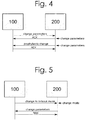
- Fig. 4 illustrates processes in a conflict resolution system according to embodiments.
- a high-criticality command is issued in normal mode by the remote control center 100 to change some parameters at the remotely controlled device 200.
- the device 200 changes the parameters and responds with an acknowledgement.
- the device 200 thereafter issues a command and changes parameters itself prophylactically, i.e., prior to receiving the acknowledgement from the control center. If the remote control center 100 were to refuse the change, the device 200 would revert the changes.
- Fig. 5 illustrates processes in a conflict resolution system according to embodiments.
- the remote control center 100 changes the control mode of the device 200 to the lockout mode due to an emergency.
- the device 200 can then no longer perform any action before receiving an acknowledgement from the remote control center 100.
- the device 200 tried to change some parameters after the device 200 had entered the lockout mode, and this change is denied by the remote control center 100.
- Fig. 7 shows a flow diagram of a conflict resolution method 600 for a remotely controlled device 200.
- a command for the device 200 can be issued by a remote control center 100 or by the device 200.
- a criticality level of the command can be determined.
- the command can be sent to the other one of the device 200 and the control center 100 for acknowledgment or refusal of the command.
- the command can be executed or disregarded by the device 200 depending on the criticality level of the command and, if applicable, on the acknowledgment or refusal of the command.
Landscapes
- Engineering & Computer Science (AREA)
- Theoretical Computer Science (AREA)
- Software Systems (AREA)
- Physics & Mathematics (AREA)
- General Engineering & Computer Science (AREA)
- General Physics & Mathematics (AREA)
- Computing Systems (AREA)
- Quality & Reliability (AREA)
- Mathematical Physics (AREA)
- Signal Processing (AREA)
- Computer Networks & Wireless Communication (AREA)
- Selective Calling Equipment (AREA)
- Telephonic Communication Services (AREA)
- Studio Devices (AREA)
Abstract
Description
- Aspects of the invention relate to a conflict resolution method for a remotely controlled device. Further aspects relate to a conflict resolution system.
- Concepts for remotely controlled devices, e.g. vessels, that are at least partially controlled by sending commands to the vessel from a control center are known. However, during the transition to such remotely controlled vessels and also after the transition in certain situations, there will be an on-board crew on the vessel, and commands can come from both the on-board crew and the control center. This can lead to situations where commands are issued by the on-board crew and a control center that are conflicting, requiring some form of resolution mechanism. Failure to resolve such conflicts can endanger both the safety and the security of a vessel.
- In other words, for (partially) remotely controlled vessels with hybrid control, i.e., some control exercised by an on-board crew, control conflicts can happen, such as conflicting commands being issued by the control center and an on-board crew. Unless such conflicts are resolved, the safety and security of a vessel can be endangered. Additionally, there are other situations that require control conflict resolution, for example attacks where a vessel has been taken over by pirates and on-board control should be locked out, or situations where the control center has to take control because the crew is incapacitated.
- Thus, there is a need for a conflict resolution method for a remotely controlled device and a conflict resolution system that overcome in least in part some of these problems, in particular that can provide a mechanism to mitigate or resolve such conflicts.
- In view of the above, a conflict resolution method for a remotely controlled device according to claim 1, and a conflict resolution system according to claim 12 are provided.
- According to an aspect, conflict resolution method for a remotely controlled device is provided. The conflict resolution method includes: issuing a command for the device by a remote control center or by the device; determining a criticality level of the command; depending on the criticality level of the command, sending the command to the other one of the device and the control center for acknowledgment or refusal of the command; and executing or disregarding the command by the device depending on the criticality level of the command and, if applicable, on the acknowledgment or refusal of the command.
- According to a further aspect, a conflict resolution system is provided. The conflict resolution system includes: a device to be remotely controlled; and a remote control center, wherein the at least one of the device and the control center is configured to issue a command for the device; determine a criticality level of the command; and depending on the criticality level of the command, send the command to the other one of the device and the control center for acknowledgment or refusal of the command, wherein the device is configured to execute or disregard the command depending on the criticality level of the command and, if applicable, on the acknowledgment or refusal of the command.
- An advantage is that conflicting commands can be resolved and a secure and reliable remote control of the device can be provided.
- Further advantages, features, aspects and details that can be combined with embodiments described herein are evident from the dependent claims, the description and the drawings.
- The details will be described in the following with reference to the figures, wherein
- Fig. 1
- is a schematic view of a conflict resolution system according to embodiments;
- Fig. 2
- is a schematic view of a conflict resolution system according to embodiments;
- Fig. 3
- is a schematic view of a conflict resolution system according to embodiments;
- Fig. 4
- is a view illustrating processes in a conflict resolution system according to embodiments;
- Fig. 5
- is a view illustrating processes in a conflict resolution system according to embodiments; and
- Fig. 7
- is a flow diagram of a conflict resolution method according to embodiments.
- Reference will now be made in detail to the various embodiments, one or more examples of which are illustrated in each figure. Each example is provided by way of explanation and is not meant as a limitation. For example, features illustrated or described as part of one embodiment can be used on or in conjunction with any other embodiment to yield yet a further embodiment. It is intended that the present disclosure includes such modifications and variations.
- Within the following description of the drawings, the same reference numbers refer to the same or to similar components. Generally, only the differences with respect to the individual embodiments are described. Unless specified otherwise, the description of a part or aspect in one embodiment applies to a corresponding part or aspect in another embodiment as well.
- The present disclosure provides mechanisms for control conflict resolution, e.g. when commands from an on-board crew and a device are conflicting with commands from a remote control center. The present application proposes such conflict resolution mechanisms, as well as concepts for situations where control needs to be assumed by one party (e.g., in order to prevent attackers from taking control of the device or to take over control from an incapacitated crew).
- In situations where a remotely controlled device, such as a vessel, still has an on-board crew, or a partial on-board crew (e.g., an engineering team), it is possible that commands issued by a remote control center conflict with commands issued locally by the on-board crew. Depending on the criticality of a command, this can lead to safety-critical issues (e.g., conflicting steering commands).
- To prevent these issues, embodiments described herein can work with different criticality levels and/or control modes of commands. The criticality level of a command may determine under which modalities a command can be executed. The control mode may determine the larger division of responsibilities between the remote control center and the device.
- In particular, each command can be assigned a criticality level, which may determine whether any acknowledgement by the opposite party (either the remote control center or the device) is necessary before a command can be executed. Generally speaking, commands with a low criticality level typically do not require an acknowledgement before being executed. Commands with a high criticality level can require acknowledgement before they can be executed on the device. In addition, there may be a provision for executing commands prophylactically and requiring a retroactive acknowledgement, e.g. for situations where quick reaction times are required (e.g., avoiding a collision), and/or the regular procedure of obtaining an acknowledgement cannot be followed. If the command is not acknowledged within a specified time frame, the action can be reversed by reverting system parameters to the parameters before the prophylactic action was carried out (e.g., changing the course back to the original course).
-
Fig. 1 shows a conflict resolution system. The conflict resolution system includes adevice 200 to be remotely controlled and/or aremote control center 100. Although the present disclosure is described in the context of a remotely controlled vessel (e.g., a ship) in several instances, thedevice 200 can be any remotely controlled device, such as an asset, e.g., a remotely controlled machinery in a mine. According to embodiments described herein, thedevice 200 can be a moveable vessel. Further, thedevice 200 can be a device able to perform a physical task. Furthermore, thedevice 200 can include an actuator for moving thedevice 200 and/or changing a direction of travel of thedevice 200. - According to embodiments described herein, the
device 200 can be a moveable vessel and/or the control center can be stationary. Further, the control center can be a moveable vessel and/or can be on board of a moveable vessel. According to embodiments described herein, thedevice 200 and thecontrol center 100 can be remote from each other. - The
device 200 and/or theremote control center 100 can be configured for establishing a communicative link to the other one of thedevice 200 and theremote control center 100 in order to communicate with the other one of thedevice 200 and theremote control center 100. - At least one of the
device 200 and theremote control center 100 can be configured to issue a command for thedevice 200. The command can be issued by a system component of the at least one of thedevice 200 and theremote control center 100. The system component can issue the command on its own, i.e. by an automatic process, or on behalf of an operator who manually issues the command. - The at least one of the
device 200 and theremote control center 100 can be configured to determine a criticality level of the command. In the context of the present disclosure, a "criticality level", such as the criticality level determined by the at least one of thedevice 200 and theremote control center 100, can be understood as an value that may determine under which modalities a command can be executed. Specifically the criticality level may determine whether any acknowledgement by the opposite party (the other one of thedevice 200 and the remote control center 100) is necessary before a command can be executed. The criticality level may take several values, e.g. from low to high, specifically low and high. Commands with a low criticality level may not require an acknowledgement before being executed. Commands with a high criticality level may require acknowledgement before they can be executed on thedevice 200. - The at least one of the
device 200 and theremote control center 100 can be configured to send the command to the other one of thedevice 200 and thecontrol center 100 for acknowledgment and/or refusal of the command. The at least one of thedevice 200 and theremote control center 100 can be configured to send the command to the other one of thedevice 200 and thecontrol center 100 depending on the criticality level of the command. - That is, the command can be sent to the other one of the
device 200 and thecontrol center 100 if the criticality level of the command indicates that an acknowledgement by the other one of thedevice 200 and thecontrol center 100 is required. For a low criticality level, the command may not be sent to the other one of thedevice 200 and the control center for acknowledgment or refusal of the command. For a high criticality level, the command may be sent to the other one of thedevice 200 and the control center for acknowledgment or refusal of the command. - According to embodiments described herein, necessity of an acknowledgement for executing the command depends on the criticality level of the command. According to embodiments described herein, the command can be sent to the other one of the
device 200 and thecontrol center 100 for acknowledgment or refusal of the command, specifically if the criticality level is high. According to embodiments described herein, the command may not sent to the other one of thedevice 200 and thecontrol center 100 for acknowledgment or refusal of the command if the criticality level is low. - The
device 200 can be configured to execute or disregard the command depending on the criticality level of the command. Further, if applicable, thedevice 200 can be configured to execute or disregard the command depending on the acknowledgment or refusal of the command. For instance, for commands having a low criticality level, thedevice 200 can be configured to execute the command without awaiting an acknowledgment. For commands having a high criticality level, thedevice 200 can be configured to execute the command after receipt of the acknowledgment. If thedevice 200 does not receive an acknowledgment for a command having a high criticality level or a refusal thereof, thedevice 200 can be configured not to execute the command. - Although the
remote control center 100 and/ordevice 200, specifically an operator having access to theremote control center 100 and/ordevice 200, can acknowledge or refuse the command, theremote control center 100 and/ordevice 200 may not be forced to react on the command. For instance, theremote control center 100 and/ordevice 200 can ignore the command. In such a situation, no acknowledgment or refusal will be sent to the other one of theremote control center 100 anddevice 200. - After receiving the command, the
device 200 can carry out the command. Specifically, thedevice 200 may perform a certain task given by the command. For instance, in case of thedevice 200 being a vessel, the command can instruct the vessel to perform a certain maneuver, such as turn left. The command may be issued by an operator on thedevice 200, such as an on-board crew, captain or pilot, or may be issued by an operator remote from thedevice 200. Furthermore, the command may trigger a maintenance task or a release. - The present disclosure enables remote control of devices and enables more sophisticated remote control applications, such as remotely controlled devices. Furthermore, embodiments of the present application can improve the safety and security of remotely controlled devices.
- According to embodiments described herein, the criticality level of the command can be changed. Specifically, the criticality level of the command can be changed while the
device 200 is performing its intended operation. The intended operation of the device may be the normal operation of thedevice 200, i.e. whatever thedevice 200 is designed for. That is, there may no maintenance stop or the like be required for changing the criticality level. - Although one
device 200 is shown inFig. 1 , any number ofdevices 200 can be provided.Figs. 2 and 3 show at least twodevices 200a, 200b. Accordingly, the conflict resolution system can include at least twodevices 200a, 200b. The at least two devices each can be identical or similar to thedevice 200. Further, the at least twodevices device 200 in common. -
Fig. 2 shows communicative link being established between theremote control center 100 and afirst device 200a of the at least twodevices 200a, 200b in order to provide communication between theremote control center 100 and afirst device 200a of the at least twodevices 200a, 200b. Further, at least one of thefirst device 200a and a second device 200b of the at least twodevices 200a, 200b can be configured for establishing a communicative link to the other one of thefirst device 200a and a second device 200b of the at least twodevices 200a, 200b in order to communicate with the other one of thefirst device 200a and a second device 200b of the at least twodevices 200a, 200b. With the above communication scheme, theremote control center 100 may communicate with thefirst device 200a of the at least twodevices 200a, 200b. For example if the command is intended for the second device 200b of the at least twodevices 200a, 200b, thefirst device 200a of the at least twodevices 200a, 200b can forward the command to the second device 200b of the at least twodevices 200a, 200b. Thereby, also a communication between theremote control center 100 and the second device 200b of the at least twodevices 200a, 200b can be established, specifically with thefirst device 200a of the at least twodevices 200a, 200b as an intermediate player. -
Fig. 3 shows a further communication link being established between theremote control center 100 and the second device 200b of the at least twodevices 200a, 200b in order to provide communication between theremote control center 100 and the second device 200b of the at least twodevices 200a, 200b. When practicing embodiments, reliability of the communicative link can be improved. Specifically, theremote control center 100 needs to be in communication reach with only one of the at least twodevices 200a, 200b, while the one device of the at least twodevices 200a, 200b being in communication with theremote control center 100 can act as a relay for the communication to the other devices of the at least twodevices 200a, 200b. - According to embodiments described herein, at least one of the
remote control center 100 and thedevice 200, specifically and at least one of the at least twodevices 200a, 200b, may include a network interface for connecting the device to a data network, in particular a global data network. The data network may be a TCP/IP network such as the Internet. The at least one of theremote control center 100 and thedevice 200, specifically and at least one of the at least twodevices 200a, 200b, can be operatively connected to the network interface for carrying out commands received from the data network. The commands may include a control command for controlling the device to carry out a task such as moving thedevice 200 and/or changing a direction of travel of thedevice 200. In this case, thedevice 200 can be adapted for carrying out the task in response to the control command. The commands may include a status request. In response to the status request, or without prior status request, the at least one of theremote control center 100 and thedevice 200, specifically and at least one of the at least twodevices 200a, 200b, may be adapted for sending a status information to the network interface, and the network interface is then adapted for sending the status information over the network. The commands may include an update command including update data. In this case, the at least one of theremote control center 100 and thedevice 200, specifically and at least one of the at least twodevices 200a, 200b, can be adapted for initiating an update in response to the update command and using the update data. - The data network may be an Ethernet network using TCP/IP such as a LAN, WAN or the Internet. The data network may include distributed storage units such as a cloud. Depending on the application, the cloud can be in form of public, private, hybrid or community cloud.
- The network interface can be configured to transceive digital signal/data between the at least one of the
remote control center 100 and thedevice 200, specifically and at least one of the at least twodevices 200a, 200b, and the data network, wherein the digital signal/data include operational command and/or information about the device or the network. Specifically, the network interface and/or the data network can be used for establishing the communicative link between theremote control center 100 and thedevice 200, specifically and at least one of the at least twodevices 200a, 200b. - While it is sometimes referred to "a
device 200" and sometimes to "at least twodevices 200a, 200b" in the present disclosure, it is envisaged that that any of these references may refer to the other one. Accordingly, unless stated otherwise, whenever it is referred to "adevice 200" this reference can be understood as referring to "at least twodevices 200a, 200b" too. That is, the wording "adevice 200" can encompass the wording "at least twodevices 200a, 200b". - According to embodiments described herein, a control mode of the
device 200 can be determined. At least one of thedevice 200 and theremote control center 100 can be configured to determine the control mode. Specifically, the one of thedevice 200 and theremote control center 100 determining the criticality level of the command can determine the control mode of thedevice 200. According to embodiments described herein, sending the command and executing or disregarding the command can further depend on the control mode of thedevice 200. - The control mode can include a normal mode, a remote control center priority mode, a device priority mode, a remote control center lockout mode and a device lockout mode.
- According to embodiments described herein, the command can be sent to the other one of the
device 200 and theremote control center 100 for acknowledgment or refusal of the command irrespective of the criticality level when the control mode is set to a priority mode for the other one of thedevice 200 and theremote control center 100 issuing the command. - According to embodiments described herein, the command can be disregarded when the control mode is set to a lockout mode for the one of the
device 200 and thecontrol center 100 issuing the command. - According to embodiments described herein, the command needs to be acknowledged by the other one of the
device 200 and thecontrol center 100 irrespective of the criticality level when the control mode is set to a lockout mode for the one of thedevice 200 and thecontrol center 100 issuing the command. - Table 1 shows an overview of control modes and priority rankings assigned to the
remote control center 100 and thedevice 200 for the control modes.[Table 1] Control Mode Remote Control Center Device Normal no priority no priority Remote Control Center Priority priority no priority Device Priority no priority priority Remote Control Center Lockout no priority absolute priority Device Lockout absolute priority no priority - In the normal control mode (see Table 2), the
remote control center 100 and thedevice 200 can have equal priority. Accordingly, whether a command needs to be acknowledged can depend on the criticality level of the command. Specifically, whether a command needs to be acknowledged can depend only on the criticality level of the command. As can be seen from Table 2, if theremote control center 100 sends a command with low criticality to thedevice 200, no acknowledgement is necessary from thedevice 200, e.g. the on-board crew, before the command is executed. Likewise, if thedevice 200 issues a command, theremote control center 100 does not need to acknowledge the command before it is executed on thedevice 200. If, on the other hand, theremote control center 100 sends a command with high criticality, thedevice 200 needs to acknowledge the command before it is executed. Likewise, if thedevice 200 issues a command with high criticality, theremote control center 100 needs to acknowledge the command before it is executed on the device. - In addition, prophylactic execution with retroactive acknowledgement is possible from either side. According to embodiments described herein, the command can be executed before the
device 200 receives an acknowledgment or refusal of the command. Further, execution of the command can be rolled-back if thedevice 200 receives a refusal of the command after starting execution of the command.[Table 2] Criticality Level Remote Control Center Device Low Criticality Level no acknowledgement no acknowledgement High Criticality Level mandatory acknowledgement mandatory acknowledgement - In the remote control center priority mode (see Table 3), the commands of the
remote control center 100 can take priority. Accordingly, if theremote control center 100 issues a command, the command can be directly executed, specifically without requiring an acknowledgement by thedevice 200, e.g. the on-board crew, irrespective of the criticality level of the command. Further, if a command is issued by thedevice 200, it has to be acknowledged by the remote control center before it can be executed, irrespective of the criticality level of the command. - According to embodiments described herein, the command can be sent to the
remote control center 100 for acknowledgment or refusal of the command irrespective of the criticality level when the control mode is set to a priority mode for theremote control center 100. - Furthermore, the
device 200 can execute commands prophylactically with retroactive acknowledgement, specifically if circumstances require it (e.g., emergency situations).[Table 3] Criticality Level Remote Control Center Device Low Criticality Level no acknowledgement mandatory acknowledgement High Criticality Level no acknowledgement mandatory acknowledgement - In the device priority mode (see Table 4), commands issued by the
device 200 can take priority over the commands issued by theremote control center 100. Accordingly, commands issued by theremote control center 100 may need to be acknowledged by thedevice 200, irrespective of the criticality level. Command issued by thedevice 200 can be executed directly. - According to embodiments described herein, the command can be sent to the
device 200 for acknowledgment or refusal of the command irrespective of the criticality level when the control mode is set to a priority mode for thedevice 200. - Further, the control center can issue commands that are executed prophylactically with retroactive acknowledgement, e.g. for emergency situations.
[Table 4] Criticality Level Remote Control Center Device Low Criticality Level mandatory acknowledgement no acknowledgement High Criticality Level mandatory acknowledgement no acknowledgement - In the remote control center lockout mode (see Table 5), the
device 200 can issue commands without acknowledgement by theremote control center 100. Further, all commands issued by theremote control center 100 may have to be acknowledged. Further, no retroactive acknowledgement by the control center may be available. The remote control center lockout mode may be intended for extreme situations, such as theremote control center 100 being taken over by enemy forces. - According to embodiments described herein, a command issued by the
remote control center 100 can be disregarded when the control mode is set to a lockout mode forremote control center 100 issuing the command. - According to embodiments described herein, the command needs to be acknowledged by the
device 200 irrespective of the criticality level when the control mode is set to a lockout mode for thecontrol center 100 issuing the command.[Table 5] Criticality Level Remote Control Center Device Low Criticality Level mandatory acknowledgement, no prophylactic execution no acknowledgement High Criticality Level mandatory acknowledgement, no prophylactic execution no acknowledgement - In the device lockout mode (see Table 6), the
remote control center 100 can issue commands without acknowledgement by thedevice 200. Further, all commands issued by thedevice 200 have to be acknowledged. In addition, thedevice 200 cannot execute commands prophylactically with retroactive acknowledgement by theremote control center 100. The device lockout mode can be intended for extreme situations, such as adevice 200 being boarded by pirates.[Table 6] Criticality Level Remote Control Center Device Low Criticality Level no acknowledgement mandatory acknowledgement, no prophylactic execution High Criticality Level no acknowledgement mandatory acknowledgement, no prophylactic execution - According to embodiments described herein, the control mode of the
device 200 can be changed. Specifically, the control mode of thedevice 200 can be changed while thedevice 200 is performing its intended operation. The intended operation of the device may be the normal operation of thedevice 200, i.e. whatever thedevice 200 is designed for. That is, there may no maintenance stop or the like be required for changing the control mode. The control mode can be changed by at least one of thedevice 200 and theremote control center 100. Further, when the control mode is set to a lockout mode for one of thedevice 200 and thecontrol center 100, the one of thedevice 200 and thecontrol center 100 being set to lockout mode may not be able to change the control mode. - Further, the control mode can be changed dynamically, e.g. depending on circumstances. To ensure that the conflict resolution system if still conflict-free, the transition to a different mode may follow control center priority, Accordingly, the
remote control center 100 can change the mode without acknowledgement. If thedevice 200 issues a command to change the mode, the control center needs to acknowledge the command first (see Table 7).[Table 7] Remote Control Center Device Mode Transition no acknowledgement mandatory acknowledgement, no prophylactic execution -
Fig. 4 illustrates processes in a conflict resolution system according to embodiments. InFig. 4 , a high-criticality command is issued in normal mode by theremote control center 100 to change some parameters at the remotely controlleddevice 200. Thedevice 200 changes the parameters and responds with an acknowledgement. - As further shown in
Fig. 4 , thedevice 200 thereafter issues a command and changes parameters itself prophylactically, i.e., prior to receiving the acknowledgement from the control center. If theremote control center 100 were to refuse the change, thedevice 200 would revert the changes. - Fig. 5 illustrates processes in a conflict resolution system according to embodiments. In Fig. 5, the
remote control center 100 changes the control mode of thedevice 200 to the lockout mode due to an emergency. Thedevice 200 can then no longer perform any action before receiving an acknowledgement from theremote control center 100. In the example of Fig. 5, thedevice 200 tried to change some parameters after thedevice 200 had entered the lockout mode, and this change is denied by theremote control center 100. - Fig. 7 shows a flow diagram of a conflict resolution method 600 for a remotely controlled
device 200. Inblock 710, a command for thedevice 200 can be issued by aremote control center 100 or by thedevice 200. Inblock 720, a criticality level of the command can be determined. Inblock 730, depending on the criticality level of the command, the command can be sent to the other one of thedevice 200 and thecontrol center 100 for acknowledgment or refusal of the command. Inblock 740, the command can be executed or disregarded by thedevice 200 depending on the criticality level of the command and, if applicable, on the acknowledgment or refusal of the command.
Claims (15)
- A conflict resolution method for a remotely controlled device (200, 200a, 200b), comprising:issuing a command for the device (200, 200a, 200b) by a remote control center (100) or by the device (200, 200a, 200b);determining a criticality level of the command;depending on the criticality level of the command, sending the command to the other one of the device (200, 200a, 200b) and the control center (100) for acknowledgment or refusal of the command; andexecuting or disregarding the command by the device (200, 200a, 200b) depending on the criticality level of the command and, if applicable, on the acknowledgment or refusal of the command.
- The method according to claim 1, wherein necessity of an acknowledgement for executing the command depends on the criticality level of the command.
- The method according to any one of claims 1 or 2, further comprising:changing the criticality level of the command, specifically while the device (200, 200a, 200b) is performing its intended operation.
- The method according to any one of claims 1 to 3, wherein the command is sent to the other one of the device (200, 200a, 200b) and the control center (100) for acknowledgment or refusal of the command, specifically if the criticality level is high.
- The method according to any one of claims 1 or 4, wherein the command is not sent to the other one of the device (200, 200a, 200b) and the control center (100) for acknowledgment or refusal of the command if the criticality level is low.
- The method according to any one of claims 1 or 5, further comprising:determining a control mode of the device (200, 200a, 200b),wherein sending the command and executing or disregarding the command further depend on the control mode of the device (200, 200a, 200b).
- The method according to claim 6, wherein the command is sent to the other one of the device (200, 200a, 200b) and the remote control center (100) for acknowledgment or refusal of the command irrespective of the criticality level when the control mode is set to a priority mode for the other one of the device (200, 200a, 200b) and the remote control center (100) issuing the command.
- The method according to claim 6, wherein the command is disregarded when the control mode is set to a lockout mode for the one of the device (200, 200a, 200b) and the control center (100) issuing the command.
- The method according to claim 6, wherein the command needs to be acknowledged by the other one of the device (200, 200a, 200b) and the control center (100) irrespective of the criticality level when the control mode is set to a lockout mode for the one of the device (200, 200a, 200b) and the control center (100) issuing the command.
- The method according to any one of claims 6 to 9, further, comprising:changing the control mode of the device (200, 200a, 200b), specifically while the device (200, 200a, 200b) is performing its intended operation.
- The method according to any one of claims 1 to 10, wherein the command is executed before the device (200, 200a, 200b) receives an acknowledgment or refusal of the command, specifically wherein execution of the command is rolled-back if the device (200, 200a, 200b) receives a refusal of the command after starting execution of the command.
- A conflict resolution system, comprising:a device (200, 200a, 200b) to be remotely controlled; anda remote control center (100),wherein the at least one of the device (200, 200a, 200b) and the control center (100) is configured toissue a command for the device (200, 200a, 200b);determine a criticality level of the command; anddepending on the criticality level of the command, send the command to the other one of the device (200, 200a, 200b) and the control center (100) for acknowledgment or refusal of the command,wherein the device (200, 200a, 200b) is configured toexecute or disregard the command depending on the criticality level of the command and, if applicable, on the acknowledgment or refusal of the command.
- The conflict resolution system of claim 12, wherein the device (200, 200a, 200b) is a moveable vessel and/or the control center (100) is stationary.
- The conflict resolution system of claim 12 or 13, wherein the device (200, 200a, 200b), and the control center (100) are remote from each other.
- The conflict resolution system of any one of claims 12 to 14, wherein at least one of the device (200, 200a, 200b), and the control center (100) comprises a network interface for connecting the device (200, 200a, 200b) to a data network, in particular a global data network, specifically wherein the at least one of the device (200, 200a, 200b), server and the at least one control interface is operatively connected to the network interface for at least one of carrying out a command received from the data network and sending device (200, 200a, 200b) status information to the data network.
Priority Applications (6)
| Application Number | Priority Date | Filing Date | Title |
|---|---|---|---|
| FIEP17191639.8T FI3457637T3 (en) | 2017-09-18 | 2017-09-18 | Conflict resolution method for a remotely controlled device and conflict resolution system |
| EP17191639.8A EP3457637B1 (en) | 2017-09-18 | 2017-09-18 | Conflict resolution method for a remotely controlled device and conflict resolution system |
| JP2020515921A JP7049445B2 (en) | 2017-09-18 | 2018-09-13 | Conflict resolution method and conflict resolution system for remote controller |
| PCT/EP2018/074762 WO2019053133A1 (en) | 2017-09-18 | 2018-09-13 | Conflict resolution method for a remotely controlled device and conflict resolution system |
| SG11202002054QA SG11202002054QA (en) | 2017-09-18 | 2018-09-13 | Conflict resolution method for a remotely controlled device and conflict resolution system |
| US16/822,534 US12299481B2 (en) | 2017-09-18 | 2020-03-18 | Conflict resolution method for a remotely controlled device and conflict resolution system |
Applications Claiming Priority (1)
| Application Number | Priority Date | Filing Date | Title |
|---|---|---|---|
| EP17191639.8A EP3457637B1 (en) | 2017-09-18 | 2017-09-18 | Conflict resolution method for a remotely controlled device and conflict resolution system |
Publications (2)
| Publication Number | Publication Date |
|---|---|
| EP3457637A1 true EP3457637A1 (en) | 2019-03-20 |
| EP3457637B1 EP3457637B1 (en) | 2022-12-21 |
Family
ID=59966566
Family Applications (1)
| Application Number | Title | Priority Date | Filing Date |
|---|---|---|---|
| EP17191639.8A Active EP3457637B1 (en) | 2017-09-18 | 2017-09-18 | Conflict resolution method for a remotely controlled device and conflict resolution system |
Country Status (6)
| Country | Link |
|---|---|
| US (1) | US12299481B2 (en) |
| EP (1) | EP3457637B1 (en) |
| JP (1) | JP7049445B2 (en) |
| FI (1) | FI3457637T3 (en) |
| SG (1) | SG11202002054QA (en) |
| WO (1) | WO2019053133A1 (en) |
Families Citing this family (3)
| Publication number | Priority date | Publication date | Assignee | Title |
|---|---|---|---|---|
| GB201715761D0 (en) | 2017-09-28 | 2017-11-15 | A P Moller-Maersk As | A method and system for operating a ship |
| GB201715760D0 (en) * | 2017-09-28 | 2017-11-15 | A P Møller Mærsk As | A method and system for operating a ship |
| CN112312367B (en) * | 2019-08-01 | 2024-11-15 | 联发科技(新加坡)私人有限公司 | Bluetooth communication method and communication device |
Citations (3)
| Publication number | Priority date | Publication date | Assignee | Title |
|---|---|---|---|---|
| US5519709A (en) * | 1994-05-04 | 1996-05-21 | Hewlett-Packard Company | Two priority fair distribution round robin protocol for a network having cascaded hubs |
| US20100195503A1 (en) * | 2009-01-28 | 2010-08-05 | Headwater Partners I Llc | Quality of service for device assisted services |
| US20120317132A1 (en) * | 2011-06-07 | 2012-12-13 | Microsoft Corporation | Instance-Based Command Execution, Approval, and Notification Framework |
Family Cites Families (36)
| Publication number | Priority date | Publication date | Assignee | Title |
|---|---|---|---|---|
| US5471253A (en) * | 1994-03-28 | 1995-11-28 | Nguyen; Dien V. | Video/audio electronic device control signal source selection switch |
| US6133867A (en) * | 1998-01-02 | 2000-10-17 | Eberwine; David Brent | Integrated air traffic management and collision avoidance system |
| US6792321B2 (en) * | 2000-03-02 | 2004-09-14 | Electro Standards Laboratories | Remote web-based control |
| US6633800B1 (en) * | 2001-01-31 | 2003-10-14 | Ainsworth Inc. | Remote control system |
| US6573839B2 (en) * | 2001-09-25 | 2003-06-03 | Stephen G. Kimmet | Aircraft catastrophic security system |
| JP2003120984A (en) | 2001-10-17 | 2003-04-23 | Sharp Corp | Air conditioner and control method thereof |
| JP4736659B2 (en) * | 2005-09-15 | 2011-07-27 | ソニー株式会社 | Multi-screen television receiver remote control system, remote controller and operation method, multi-screen television receiver and operation method, recording medium, and program |
| US8270933B2 (en) * | 2005-09-26 | 2012-09-18 | Zoomsafer, Inc. | Safety features for portable electronic device |
| JP2007131275A (en) | 2005-11-14 | 2007-05-31 | Toshiba Mitsubishi-Electric Industrial System Corp | Diagnostic system of marine equipment using communication satellite and internet |
| US7725635B2 (en) * | 2007-03-18 | 2010-05-25 | Moxa Inc. | Method of determining request transmission priority subject to request channel and transmitting request subject to such request transmission priority in application of fieldbus communication framework |
| US7603500B2 (en) * | 2007-08-10 | 2009-10-13 | Dell Products L.P. | System and method for allowing coexistence of multiple PCI managers in a PCI express system |
| US20090174362A1 (en) * | 2008-01-03 | 2009-07-09 | F.D. Richardson Enterprises, Inc. Doing Business As Richardson Jumpstarters | Method and apparatus for providing supplemental power to an engine |
| JP5248180B2 (en) | 2008-04-17 | 2013-07-31 | シャープ株式会社 | Operation target device, permission input device, operation target data providing device, remote operation system, control method, control program, and computer-readable recording medium storing the program |
| US8384250B2 (en) * | 2008-08-01 | 2013-02-26 | Verizon Patent And Licensing Inc. | Computer-controlled connector-panel system |
| WO2010043967A1 (en) * | 2008-10-17 | 2010-04-22 | Frank Wegner Donnelly | Rail conveyance system for mining |
| JP5272719B2 (en) * | 2008-12-24 | 2013-08-28 | 富士通セミコンダクター株式会社 | Data transfer apparatus and data transfer method |
| US20110006880A1 (en) * | 2009-07-09 | 2011-01-13 | Medtronic Minimed, Inc. | Fingerprint-linked control of a portable medical device |
| US9009717B2 (en) * | 2009-10-29 | 2015-04-14 | International Business Machines Corporation | Managing scheduling of processes |
| US8463953B2 (en) * | 2010-08-18 | 2013-06-11 | Snap-On Incorporated | System and method for integrating devices for servicing a device-under-service |
| US20160194014A1 (en) * | 2010-11-17 | 2016-07-07 | General Electric Company | Vehicular data communication systems |
| US9529635B2 (en) * | 2011-10-24 | 2016-12-27 | Plumchoice, Inc. | Systems and methods for configuring and launching automated services to a remote device |
| FR2982961B1 (en) * | 2011-11-22 | 2014-09-05 | Schneider Electric Usa Inc | ARBITRATION OF PRIORITY CONTROL DEVICE |
| JP6219858B2 (en) * | 2012-03-09 | 2017-10-25 | トムソン ライセンシングThomson Licensing | Distributed control of synchronized content |
| US9619303B2 (en) * | 2012-04-11 | 2017-04-11 | Hewlett Packard Enterprise Development Lp | Prioritized conflict handling in a system |
| US20130318720A1 (en) * | 2012-06-01 | 2013-12-05 | Chg Hospital Beds Inc. | Patient support with improved patient safety |
| JP5653409B2 (en) | 2012-08-30 | 2015-01-14 | 三菱電機株式会社 | Device control apparatus, device control method, and program |
| US9145863B2 (en) * | 2013-03-15 | 2015-09-29 | General Electric Company | System and method for controlling automatic shut-off of an engine |
| EP2711861A1 (en) * | 2012-09-20 | 2014-03-26 | Alcatel-Lucent | Method and system of controlling changes in an operating system |
| JP2014110517A (en) * | 2012-11-30 | 2014-06-12 | Toshiba Corp | Remote control management device, control method, and control program |
| CN105845639B (en) * | 2015-01-16 | 2019-03-19 | 恒劲科技股份有限公司 | Electronic packaging structure and conductive structure |
| US9871772B1 (en) * | 2015-03-17 | 2018-01-16 | The Charles Stark Draper Laboratory, Inc. | Cryptographic system for secure command and control of remotely controlled devices |
| WO2017131094A1 (en) * | 2016-01-28 | 2017-08-03 | 京セラ株式会社 | Power generation system, method for controlling power generation system, and power generation device |
| US10705519B2 (en) * | 2016-04-25 | 2020-07-07 | Transportation Ip Holdings, Llc | Distributed vehicle system control system and method |
| JP6786407B2 (en) * | 2017-01-23 | 2020-11-18 | 株式会社クボタ | Work vehicle wireless management system |
| CN108729113B (en) * | 2017-04-24 | 2021-07-06 | 重庆海尔滚筒洗衣机有限公司 | A washing machine control method and washing machine |
| US11174689B2 (en) * | 2017-09-25 | 2021-11-16 | Schlumberger Technology Corporation | Integration of mud and cementing equipment systems |
-
2017
- 2017-09-18 EP EP17191639.8A patent/EP3457637B1/en active Active
- 2017-09-18 FI FIEP17191639.8T patent/FI3457637T3/en active
-
2018
- 2018-09-13 JP JP2020515921A patent/JP7049445B2/en active Active
- 2018-09-13 WO PCT/EP2018/074762 patent/WO2019053133A1/en not_active Ceased
- 2018-09-13 SG SG11202002054QA patent/SG11202002054QA/en unknown
-
2020
- 2020-03-18 US US16/822,534 patent/US12299481B2/en active Active
Patent Citations (3)
| Publication number | Priority date | Publication date | Assignee | Title |
|---|---|---|---|---|
| US5519709A (en) * | 1994-05-04 | 1996-05-21 | Hewlett-Packard Company | Two priority fair distribution round robin protocol for a network having cascaded hubs |
| US20100195503A1 (en) * | 2009-01-28 | 2010-08-05 | Headwater Partners I Llc | Quality of service for device assisted services |
| US20120317132A1 (en) * | 2011-06-07 | 2012-12-13 | Microsoft Corporation | Instance-Based Command Execution, Approval, and Notification Framework |
Also Published As
| Publication number | Publication date |
|---|---|
| WO2019053133A1 (en) | 2019-03-21 |
| FI3457637T3 (en) | 2023-03-23 |
| EP3457637B1 (en) | 2022-12-21 |
| US12299481B2 (en) | 2025-05-13 |
| JP7049445B2 (en) | 2022-04-06 |
| US20200218570A1 (en) | 2020-07-09 |
| SG11202002054QA (en) | 2020-04-29 |
| JP2021501487A (en) | 2021-01-14 |
Similar Documents
| Publication | Publication Date | Title |
|---|---|---|
| US12299481B2 (en) | Conflict resolution method for a remotely controlled device and conflict resolution system | |
| US12379712B2 (en) | Control mode switching apparatus and control mode switching method | |
| RU2741448C1 (en) | Vehicle braking system and braking system operation method | |
| US20200298818A1 (en) | Autonomous ready vehicle | |
| EP3756052B1 (en) | Monitoring system for a protective device and protective device | |
| JP7008687B2 (en) | Control device and control system | |
| JP6381678B2 (en) | Method, apparatus, monitoring system and computer program for monitoring a system of a vehicle performing at least a semi-automated driving function | |
| EP3462270B1 (en) | Redundant flight control system and method of use | |
| RU2767382C1 (en) | Vehicle control system structure | |
| WO2019131002A1 (en) | Vehicle control device and electronic control system | |
| WO2018030032A1 (en) | Vehicle control device | |
| MX2019013972A (en) | Automatic parking control method and automatic parking control apparatus for vehicles. | |
| EP3758301A1 (en) | An apparatus and a method for providing a redundant communication within a vehicle architecture and a corresponding control architecture | |
| US20200341435A1 (en) | Control device | |
| CN111572515A (en) | Unmanned vehicle and unmanned vehicle braking method | |
| WO2019131003A1 (en) | Vehicle control device and electronic control system | |
| CN102705505A (en) | Engineering vehicle control equipment, control method and engineering vehicle | |
| US11159535B2 (en) | Methods for controlling a device and control system | |
| WO2021019715A1 (en) | Vehicle control device | |
| DE102019201689A1 (en) | Method and control unit for operating an autonomous vehicle | |
| US10822022B2 (en) | Transport key for a steer-by-wire steering system for motor vehicles | |
| JP7774047B2 (en) | Control system with isolated user computing unit and control method thereof | |
| KR102294558B1 (en) | Vehicle components for bidirectional control of autonomous vehicles and control method thereof | |
| EP3382568B1 (en) | Method and apparatus for communication between master and slave processors | |
| EP3483673B1 (en) | Method and computer system to consistently control a set of actuators |
Legal Events
| Date | Code | Title | Description |
|---|---|---|---|
| PUAI | Public reference made under article 153(3) epc to a published international application that has entered the european phase |
Free format text: ORIGINAL CODE: 0009012 |
|
| STAA | Information on the status of an ep patent application or granted ep patent |
Free format text: STATUS: THE APPLICATION HAS BEEN PUBLISHED |
|
| AK | Designated contracting states |
Kind code of ref document: A1 Designated state(s): AL AT BE BG CH CY CZ DE DK EE ES FI FR GB GR HR HU IE IS IT LI LT LU LV MC MK MT NL NO PL PT RO RS SE SI SK SM TR |
|
| AX | Request for extension of the european patent |
Extension state: BA ME |
|
| STAA | Information on the status of an ep patent application or granted ep patent |
Free format text: STATUS: REQUEST FOR EXAMINATION WAS MADE |
|
| STAA | Information on the status of an ep patent application or granted ep patent |
Free format text: STATUS: EXAMINATION IS IN PROGRESS |
|
| 17P | Request for examination filed |
Effective date: 20190918 |
|
| RBV | Designated contracting states (corrected) |
Designated state(s): AL AT BE BG CH CY CZ DE DK EE ES FI FR GB GR HR HU IE IS IT LI LT LU LV MC MK MT NL NO PL PT RO RS SE SI SK SM TR |
|
| 17Q | First examination report despatched |
Effective date: 20191009 |
|
| GRAP | Despatch of communication of intention to grant a patent |
Free format text: ORIGINAL CODE: EPIDOSNIGR1 |
|
| STAA | Information on the status of an ep patent application or granted ep patent |
Free format text: STATUS: GRANT OF PATENT IS INTENDED |
|
| INTG | Intention to grant announced |
Effective date: 20220707 |
|
| GRAS | Grant fee paid |
Free format text: ORIGINAL CODE: EPIDOSNIGR3 |
|
| GRAA | (expected) grant |
Free format text: ORIGINAL CODE: 0009210 |
|
| STAA | Information on the status of an ep patent application or granted ep patent |
Free format text: STATUS: THE PATENT HAS BEEN GRANTED |
|
| AK | Designated contracting states |
Kind code of ref document: B1 Designated state(s): AL AT BE BG CH CY CZ DE DK EE ES FI FR GB GR HR HU IE IS IT LI LT LU LV MC MK MT NL NO PL PT RO RS SE SI SK SM TR |
|
| RAP3 | Party data changed (applicant data changed or rights of an application transferred) |
Owner name: ABB SCHWEIZ AG |
|
| REG | Reference to a national code |
Ref country code: GB Ref legal event code: FG4D |
|
| REG | Reference to a national code |
Ref country code: CH Ref legal event code: EP |
|
| REG | Reference to a national code |
Ref country code: DE Ref legal event code: R096 Ref document number: 602017064741 Country of ref document: DE |
|
| REG | Reference to a national code |
Ref country code: AT Ref legal event code: REF Ref document number: 1539709 Country of ref document: AT Kind code of ref document: T Effective date: 20230115 |
|
| REG | Reference to a national code |
Ref country code: IE Ref legal event code: FG4D |
|
| REG | Reference to a national code |
Ref country code: NO Ref legal event code: T2 Effective date: 20221221 |
|
| REG | Reference to a national code |
Ref country code: SE Ref legal event code: TRGR |
|
| REG | Reference to a national code |
Ref country code: LT Ref legal event code: MG9D |
|
| REG | Reference to a national code |
Ref country code: NL Ref legal event code: MP Effective date: 20221221 |
|
| PG25 | Lapsed in a contracting state [announced via postgrant information from national office to epo] |
Ref country code: LT Free format text: LAPSE BECAUSE OF FAILURE TO SUBMIT A TRANSLATION OF THE DESCRIPTION OR TO PAY THE FEE WITHIN THE PRESCRIBED TIME-LIMIT Effective date: 20221221 |
|
| REG | Reference to a national code |
Ref country code: AT Ref legal event code: MK05 Ref document number: 1539709 Country of ref document: AT Kind code of ref document: T Effective date: 20221221 |
|
| PG25 | Lapsed in a contracting state [announced via postgrant information from national office to epo] |
Ref country code: RS Free format text: LAPSE BECAUSE OF FAILURE TO SUBMIT A TRANSLATION OF THE DESCRIPTION OR TO PAY THE FEE WITHIN THE PRESCRIBED TIME-LIMIT Effective date: 20221221 Ref country code: LV Free format text: LAPSE BECAUSE OF FAILURE TO SUBMIT A TRANSLATION OF THE DESCRIPTION OR TO PAY THE FEE WITHIN THE PRESCRIBED TIME-LIMIT Effective date: 20221221 Ref country code: HR Free format text: LAPSE BECAUSE OF FAILURE TO SUBMIT A TRANSLATION OF THE DESCRIPTION OR TO PAY THE FEE WITHIN THE PRESCRIBED TIME-LIMIT Effective date: 20221221 Ref country code: GR Free format text: LAPSE BECAUSE OF FAILURE TO SUBMIT A TRANSLATION OF THE DESCRIPTION OR TO PAY THE FEE WITHIN THE PRESCRIBED TIME-LIMIT Effective date: 20230322 |
|
| PG25 | Lapsed in a contracting state [announced via postgrant information from national office to epo] |
Ref country code: NL Free format text: LAPSE BECAUSE OF FAILURE TO SUBMIT A TRANSLATION OF THE DESCRIPTION OR TO PAY THE FEE WITHIN THE PRESCRIBED TIME-LIMIT Effective date: 20221221 |
|
| PG25 | Lapsed in a contracting state [announced via postgrant information from national office to epo] |
Ref country code: SM Free format text: LAPSE BECAUSE OF FAILURE TO SUBMIT A TRANSLATION OF THE DESCRIPTION OR TO PAY THE FEE WITHIN THE PRESCRIBED TIME-LIMIT Effective date: 20221221 Ref country code: RO Free format text: LAPSE BECAUSE OF FAILURE TO SUBMIT A TRANSLATION OF THE DESCRIPTION OR TO PAY THE FEE WITHIN THE PRESCRIBED TIME-LIMIT Effective date: 20221221 Ref country code: PT Free format text: LAPSE BECAUSE OF FAILURE TO SUBMIT A TRANSLATION OF THE DESCRIPTION OR TO PAY THE FEE WITHIN THE PRESCRIBED TIME-LIMIT Effective date: 20230421 Ref country code: ES Free format text: LAPSE BECAUSE OF FAILURE TO SUBMIT A TRANSLATION OF THE DESCRIPTION OR TO PAY THE FEE WITHIN THE PRESCRIBED TIME-LIMIT Effective date: 20221221 Ref country code: EE Free format text: LAPSE BECAUSE OF FAILURE TO SUBMIT A TRANSLATION OF THE DESCRIPTION OR TO PAY THE FEE WITHIN THE PRESCRIBED TIME-LIMIT Effective date: 20221221 Ref country code: CZ Free format text: LAPSE BECAUSE OF FAILURE TO SUBMIT A TRANSLATION OF THE DESCRIPTION OR TO PAY THE FEE WITHIN THE PRESCRIBED TIME-LIMIT Effective date: 20221221 Ref country code: AT Free format text: LAPSE BECAUSE OF FAILURE TO SUBMIT A TRANSLATION OF THE DESCRIPTION OR TO PAY THE FEE WITHIN THE PRESCRIBED TIME-LIMIT Effective date: 20221221 |
|
| PG25 | Lapsed in a contracting state [announced via postgrant information from national office to epo] |
Ref country code: SK Free format text: LAPSE BECAUSE OF FAILURE TO SUBMIT A TRANSLATION OF THE DESCRIPTION OR TO PAY THE FEE WITHIN THE PRESCRIBED TIME-LIMIT Effective date: 20221221 Ref country code: PL Free format text: LAPSE BECAUSE OF FAILURE TO SUBMIT A TRANSLATION OF THE DESCRIPTION OR TO PAY THE FEE WITHIN THE PRESCRIBED TIME-LIMIT Effective date: 20221221 Ref country code: IS Free format text: LAPSE BECAUSE OF FAILURE TO SUBMIT A TRANSLATION OF THE DESCRIPTION OR TO PAY THE FEE WITHIN THE PRESCRIBED TIME-LIMIT Effective date: 20230421 Ref country code: AL Free format text: LAPSE BECAUSE OF FAILURE TO SUBMIT A TRANSLATION OF THE DESCRIPTION OR TO PAY THE FEE WITHIN THE PRESCRIBED TIME-LIMIT Effective date: 20221221 |
|
| REG | Reference to a national code |
Ref country code: DE Ref legal event code: R097 Ref document number: 602017064741 Country of ref document: DE |
|
| PLBE | No opposition filed within time limit |
Free format text: ORIGINAL CODE: 0009261 |
|
| STAA | Information on the status of an ep patent application or granted ep patent |
Free format text: STATUS: NO OPPOSITION FILED WITHIN TIME LIMIT |
|
| PG25 | Lapsed in a contracting state [announced via postgrant information from national office to epo] |
Ref country code: DK Free format text: LAPSE BECAUSE OF FAILURE TO SUBMIT A TRANSLATION OF THE DESCRIPTION OR TO PAY THE FEE WITHIN THE PRESCRIBED TIME-LIMIT Effective date: 20221221 |
|
| 26N | No opposition filed |
Effective date: 20230922 |
|
| PG25 | Lapsed in a contracting state [announced via postgrant information from national office to epo] |
Ref country code: SI Free format text: LAPSE BECAUSE OF FAILURE TO SUBMIT A TRANSLATION OF THE DESCRIPTION OR TO PAY THE FEE WITHIN THE PRESCRIBED TIME-LIMIT Effective date: 20221221 |
|
| REG | Reference to a national code |
Ref country code: CH Ref legal event code: PL |
|
| PG25 | Lapsed in a contracting state [announced via postgrant information from national office to epo] |
Ref country code: LU Free format text: LAPSE BECAUSE OF NON-PAYMENT OF DUE FEES Effective date: 20230918 |
|
| REG | Reference to a national code |
Ref country code: BE Ref legal event code: MM Effective date: 20230930 |
|
| GBPC | Gb: european patent ceased through non-payment of renewal fee |
Effective date: 20230918 |
|
| PG25 | Lapsed in a contracting state [announced via postgrant information from national office to epo] |
Ref country code: LU Free format text: LAPSE BECAUSE OF NON-PAYMENT OF DUE FEES Effective date: 20230918 Ref country code: IT Free format text: LAPSE BECAUSE OF FAILURE TO SUBMIT A TRANSLATION OF THE DESCRIPTION OR TO PAY THE FEE WITHIN THE PRESCRIBED TIME-LIMIT Effective date: 20221221 Ref country code: MC Free format text: LAPSE BECAUSE OF FAILURE TO SUBMIT A TRANSLATION OF THE DESCRIPTION OR TO PAY THE FEE WITHIN THE PRESCRIBED TIME-LIMIT Effective date: 20221221 |
|
| REG | Reference to a national code |
Ref country code: IE Ref legal event code: MM4A |
|
| PG25 | Lapsed in a contracting state [announced via postgrant information from national office to epo] |
Ref country code: IE Free format text: LAPSE BECAUSE OF NON-PAYMENT OF DUE FEES Effective date: 20230918 |
|
| PG25 | Lapsed in a contracting state [announced via postgrant information from national office to epo] |
Ref country code: GB Free format text: LAPSE BECAUSE OF NON-PAYMENT OF DUE FEES Effective date: 20230918 |
|
| PG25 | Lapsed in a contracting state [announced via postgrant information from national office to epo] |
Ref country code: CH Free format text: LAPSE BECAUSE OF NON-PAYMENT OF DUE FEES Effective date: 20230930 |
|
| PG25 | Lapsed in a contracting state [announced via postgrant information from national office to epo] |
Ref country code: IE Free format text: LAPSE BECAUSE OF NON-PAYMENT OF DUE FEES Effective date: 20230918 Ref country code: GB Free format text: LAPSE BECAUSE OF NON-PAYMENT OF DUE FEES Effective date: 20230918 Ref country code: FR Free format text: LAPSE BECAUSE OF NON-PAYMENT OF DUE FEES Effective date: 20230930 Ref country code: CH Free format text: LAPSE BECAUSE OF NON-PAYMENT OF DUE FEES Effective date: 20230930 |
|
| PG25 | Lapsed in a contracting state [announced via postgrant information from national office to epo] |
Ref country code: BE Free format text: LAPSE BECAUSE OF NON-PAYMENT OF DUE FEES Effective date: 20230930 |
|
| PG25 | Lapsed in a contracting state [announced via postgrant information from national office to epo] |
Ref country code: BG Free format text: LAPSE BECAUSE OF FAILURE TO SUBMIT A TRANSLATION OF THE DESCRIPTION OR TO PAY THE FEE WITHIN THE PRESCRIBED TIME-LIMIT Effective date: 20221221 |
|
| PG25 | Lapsed in a contracting state [announced via postgrant information from national office to epo] |
Ref country code: BG Free format text: LAPSE BECAUSE OF FAILURE TO SUBMIT A TRANSLATION OF THE DESCRIPTION OR TO PAY THE FEE WITHIN THE PRESCRIBED TIME-LIMIT Effective date: 20221221 |
|
| PG25 | Lapsed in a contracting state [announced via postgrant information from national office to epo] |
Ref country code: CY Free format text: LAPSE BECAUSE OF FAILURE TO SUBMIT A TRANSLATION OF THE DESCRIPTION OR TO PAY THE FEE WITHIN THE PRESCRIBED TIME-LIMIT; INVALID AB INITIO Effective date: 20170918 |
|
| PG25 | Lapsed in a contracting state [announced via postgrant information from national office to epo] |
Ref country code: HU Free format text: LAPSE BECAUSE OF FAILURE TO SUBMIT A TRANSLATION OF THE DESCRIPTION OR TO PAY THE FEE WITHIN THE PRESCRIBED TIME-LIMIT; INVALID AB INITIO Effective date: 20170918 |
|
| PGFP | Annual fee paid to national office [announced via postgrant information from national office to epo] |
Ref country code: FI Payment date: 20250929 Year of fee payment: 9 |
|
| PGFP | Annual fee paid to national office [announced via postgrant information from national office to epo] |
Ref country code: DE Payment date: 20250919 Year of fee payment: 9 |
|
| PGFP | Annual fee paid to national office [announced via postgrant information from national office to epo] |
Ref country code: NO Payment date: 20250923 Year of fee payment: 9 |
|
| PGFP | Annual fee paid to national office [announced via postgrant information from national office to epo] |
Ref country code: SE Payment date: 20250918 Year of fee payment: 9 |
|
| PG25 | Lapsed in a contracting state [announced via postgrant information from national office to epo] |
Ref country code: TR Free format text: LAPSE BECAUSE OF FAILURE TO SUBMIT A TRANSLATION OF THE DESCRIPTION OR TO PAY THE FEE WITHIN THE PRESCRIBED TIME-LIMIT Effective date: 20221221 |