EP3457605A1 - Selective sub-carrier processing - Google Patents
Selective sub-carrier processing Download PDFInfo
- Publication number
- EP3457605A1 EP3457605A1 EP18201640.2A EP18201640A EP3457605A1 EP 3457605 A1 EP3457605 A1 EP 3457605A1 EP 18201640 A EP18201640 A EP 18201640A EP 3457605 A1 EP3457605 A1 EP 3457605A1
- Authority
- EP
- European Patent Office
- Prior art keywords
- signal
- subcarriers
- received
- receiver
- signal quality
- Prior art date
- Legal status (The legal status is an assumption and is not a legal conclusion. Google has not performed a legal analysis and makes no representation as to the accuracy of the status listed.)
- Granted
Links
Images







Classifications
-
- H—ELECTRICITY
- H04—ELECTRIC COMMUNICATION TECHNIQUE
- H04L—TRANSMISSION OF DIGITAL INFORMATION, e.g. TELEGRAPHIC COMMUNICATION
- H04L27/00—Modulated-carrier systems
- H04L27/26—Systems using multi-frequency codes
- H04L27/2601—Multicarrier modulation systems
- H04L27/2647—Arrangements specific to the receiver only
-
- H—ELECTRICITY
- H04—ELECTRIC COMMUNICATION TECHNIQUE
- H04L—TRANSMISSION OF DIGITAL INFORMATION, e.g. TELEGRAPHIC COMMUNICATION
- H04L5/00—Arrangements affording multiple use of the transmission path
- H04L5/003—Arrangements for allocating sub-channels of the transmission path
- H04L5/0058—Allocation criteria
- H04L5/006—Quality of the received signal, e.g. BER, SNR, water filling
-
- H—ELECTRICITY
- H04—ELECTRIC COMMUNICATION TECHNIQUE
- H04L—TRANSMISSION OF DIGITAL INFORMATION, e.g. TELEGRAPHIC COMMUNICATION
- H04L1/00—Arrangements for detecting or preventing errors in the information received
- H04L1/004—Arrangements for detecting or preventing errors in the information received by using forward error control
- H04L1/0045—Arrangements at the receiver end
- H04L1/0052—Realisations of complexity reduction techniques, e.g. pipelining or use of look-up tables
- H04L1/0053—Realisations of complexity reduction techniques, e.g. pipelining or use of look-up tables specially adapted for power saving
-
- H—ELECTRICITY
- H04—ELECTRIC COMMUNICATION TECHNIQUE
- H04L—TRANSMISSION OF DIGITAL INFORMATION, e.g. TELEGRAPHIC COMMUNICATION
- H04L1/00—Arrangements for detecting or preventing errors in the information received
- H04L1/004—Arrangements for detecting or preventing errors in the information received by using forward error control
- H04L1/0056—Systems characterized by the type of code used
- H04L1/0057—Block codes
-
- H—ELECTRICITY
- H04—ELECTRIC COMMUNICATION TECHNIQUE
- H04L—TRANSMISSION OF DIGITAL INFORMATION, e.g. TELEGRAPHIC COMMUNICATION
- H04L1/00—Arrangements for detecting or preventing errors in the information received
- H04L1/004—Arrangements for detecting or preventing errors in the information received by using forward error control
- H04L1/0056—Systems characterized by the type of code used
- H04L1/0071—Use of interleaving
-
- H—ELECTRICITY
- H04—ELECTRIC COMMUNICATION TECHNIQUE
- H04L—TRANSMISSION OF DIGITAL INFORMATION, e.g. TELEGRAPHIC COMMUNICATION
- H04L1/00—Arrangements for detecting or preventing errors in the information received
- H04L1/20—Arrangements for detecting or preventing errors in the information received using signal quality detector
-
- H—ELECTRICITY
- H04—ELECTRIC COMMUNICATION TECHNIQUE
- H04L—TRANSMISSION OF DIGITAL INFORMATION, e.g. TELEGRAPHIC COMMUNICATION
- H04L27/00—Modulated-carrier systems
- H04L27/26—Systems using multi-frequency codes
- H04L27/2601—Multicarrier modulation systems
- H04L27/2647—Arrangements specific to the receiver only
- H04L27/2649—Demodulators
- H04L27/2653—Demodulators with direct demodulation of individual subcarriers
-
- H—ELECTRICITY
- H04—ELECTRIC COMMUNICATION TECHNIQUE
- H04L—TRANSMISSION OF DIGITAL INFORMATION, e.g. TELEGRAPHIC COMMUNICATION
- H04L5/00—Arrangements affording multiple use of the transmission path
- H04L5/0001—Arrangements for dividing the transmission path
- H04L5/0003—Two-dimensional division
- H04L5/0005—Time-frequency
- H04L5/0007—Time-frequency the frequencies being orthogonal, e.g. OFDM(A) or DMT
-
- H—ELECTRICITY
- H04—ELECTRIC COMMUNICATION TECHNIQUE
- H04L—TRANSMISSION OF DIGITAL INFORMATION, e.g. TELEGRAPHIC COMMUNICATION
- H04L5/00—Arrangements affording multiple use of the transmission path
- H04L5/003—Arrangements for allocating sub-channels of the transmission path
- H04L5/0048—Allocation of pilot signals, i.e. of signals known to the receiver
-
- H—ELECTRICITY
- H04—ELECTRIC COMMUNICATION TECHNIQUE
- H04W—WIRELESS COMMUNICATION NETWORKS
- H04W52/00—Power management, e.g. Transmission Power Control [TPC] or power classes
- H04W52/02—Power saving arrangements
- H04W52/0209—Power saving arrangements in terminal devices
-
- H—ELECTRICITY
- H04—ELECTRIC COMMUNICATION TECHNIQUE
- H04W—WIRELESS COMMUNICATION NETWORKS
- H04W52/00—Power management, e.g. Transmission Power Control [TPC] or power classes
- H04W52/02—Power saving arrangements
- H04W52/0209—Power saving arrangements in terminal devices
- H04W52/0225—Power saving arrangements in terminal devices using monitoring of external events, e.g. the presence of a signal
- H04W52/0245—Power saving arrangements in terminal devices using monitoring of external events, e.g. the presence of a signal according to signal strength
-
- H—ELECTRICITY
- H04—ELECTRIC COMMUNICATION TECHNIQUE
- H04L—TRANSMISSION OF DIGITAL INFORMATION, e.g. TELEGRAPHIC COMMUNICATION
- H04L1/00—Arrangements for detecting or preventing errors in the information received
- H04L1/0001—Systems modifying transmission characteristics according to link quality, e.g. power backoff
- H04L1/0002—Systems modifying transmission characteristics according to link quality, e.g. power backoff by adapting the transmission rate
- H04L1/0003—Systems modifying transmission characteristics according to link quality, e.g. power backoff by adapting the transmission rate by switching between different modulation schemes
-
- H—ELECTRICITY
- H04—ELECTRIC COMMUNICATION TECHNIQUE
- H04L—TRANSMISSION OF DIGITAL INFORMATION, e.g. TELEGRAPHIC COMMUNICATION
- H04L1/00—Arrangements for detecting or preventing errors in the information received
- H04L1/0001—Systems modifying transmission characteristics according to link quality, e.g. power backoff
- H04L1/0009—Systems modifying transmission characteristics according to link quality, e.g. power backoff by adapting the channel coding
-
- Y—GENERAL TAGGING OF NEW TECHNOLOGICAL DEVELOPMENTS; GENERAL TAGGING OF CROSS-SECTIONAL TECHNOLOGIES SPANNING OVER SEVERAL SECTIONS OF THE IPC; TECHNICAL SUBJECTS COVERED BY FORMER USPC CROSS-REFERENCE ART COLLECTIONS [XRACs] AND DIGESTS
- Y02—TECHNOLOGIES OR APPLICATIONS FOR MITIGATION OR ADAPTATION AGAINST CLIMATE CHANGE
- Y02D—CLIMATE CHANGE MITIGATION TECHNOLOGIES IN INFORMATION AND COMMUNICATION TECHNOLOGIES [ICT], I.E. INFORMATION AND COMMUNICATION TECHNOLOGIES AIMING AT THE REDUCTION OF THEIR OWN ENERGY USE
- Y02D30/00—Reducing energy consumption in communication networks
- Y02D30/70—Reducing energy consumption in communication networks in wireless communication networks
Definitions
- the described embodiments relate generally to wireless communications. More particularly, the described embodiments relate to systems, methods and apparatuses for selectively processing sub-carriers of a received multi-carrier signal.
- An embodiment includes a receiver, wherein the receiver includes a receive chain and a controller.
- the receive chain is operative to receive a multi-carrier signal.
- the controller is operative to determine whether a signal quality of the received multi-carrier signal is better than a predetermined signal quality, wherein the predetermined signal quality is selected to ensure that a probability of error free decoding of the received signal is greater than a predetermined threshold, and determine which of subcarriers of the multicarrier signal to perform receive signal processing or which multicarrier signals not to perform receive signal processing based on a relative signal quality of each of the subcarriers after determining that the signal quality of the received multi-carrier signal is better than the predetermined signal quality.
- the embodiments described include methods, apparatuses, and systems for selectively processing sub-carriers of a received multi-carrier signal.
- the selective subcarrier processing save power as compared to receiver systems that do not include selective subcarrier processing.
- the described embodiments include identifying when selective subcarrier processing should be considered, and further, various methods of implementing the selective processing of the subcarriers.
- the transmission signals between a first transceiver and a second transceiver include multi-carrier modulation signals.
- Multi-carrier modulation is a method of transmitting data by splitting it into several components, and sending each of these components over separate carrier signals.
- the individual carriers have narrow bandwidth, but the composite signal can have broad bandwidth.
- the advantages of MCM include relative immunity to fading caused by transmission over more than one path at a time (multipath fading), less susceptibility than single-carrier systems to interference caused by impulse noise, and enhanced immunity to inter-symbol interference.
- An exemplary form of MCM includes orthogonal frequency-division multiplexing (OFDM).
- OFDM is essentially identical to coded OFDM (COFDM) and discrete multi-tone modulation (DMT), and is a frequency-division multiplexing (FDM) scheme used as a digital multi-carrier modulation method.
- COFDM coded OFDM
- DMT discrete multi-tone modulation
- FDM frequency-division multiplexing
- the primary advantage of OFDM over single-carrier schemes is its ability to cope with severe channel conditions (for example, narrowband interference and frequency-selective fading due to multipath) without complex equalization filters.
- Channel equalization is simplified because OFDM may be viewed as using many slowly modulated narrowband signals rather than one rapidly modulated wideband signal.
- the low symbol rate makes the use of a guard interval between symbols affordable, making it possible to eliminate intersymbol interference (ISI) and utilize echoes and time-spreading to achieve a diversity gain, that is, a signal-to-noise ratio improvement.
- ISI intersymbol interference
- At least some of the described embodiments include identifying when to implement selective subcarrier processing.
- Figure 1 shows a receiver portion of a transceiver that includes selective processing of subcarriers of a received multicarrier signal based on a signal quality of each subcarrier, according to an embodiment.
- synchronization is performed to determine an OFDM signal boundary on the received signal.
- a Synchronization Block 110 of a transceiver 100 in Figure 1 shows the process of synchronization where a packet is determined, for example, to be a valid OFDM signal and the symbol boundary of the OFDM signal is determined.
- the receiver estimates the channel and noise for the received signal for each subcarrier as shown in a Channel and Noise Estimator block 120 of Figure 1 .
- the receiver decodes subsequent OFDM symbols during the preamble of the OFDM symbols to determine information about the transmitted signal characteristics for the payload such as modulation, coding rate, and packet length as shown in a Decode Preamble Signal Fields block 140 and a Detect Data Rate and Coding block 150 of Figure 1 .
- a signal quality threshold is determined for the received signal, which is included, for example, in a Determine Signal Quality Threshold block 160 of Figure 1 .
- the signal quality is compared against a predetermined or the previously described signal quality threshold determined based on preamble signal processing.
- the signal quality threshold is selected to ensure that a received signal with the stated signal characteristics (that is, modulation, coding rate, packet length) could be decoded error free with probability greater than a predetermined error free probability threshold if the predetermined signal quality threshold is exceeded. If the signal quality of the received signal exceeds this predetermined signal quality threshold, then selective subcarrier processing is implemented which includes choosing a subset of all subcarriers to be processed by the receiver in order to decode the received signal.
- a common measure of signal quality is the Signal to Noise Ratio (SNR) of the received signal. The calculation of SNR along with the selection of a predetermined signal quality or SNR threshold is detailed below.
- a lookup table is then used to determine the approximate required SNR for the data rate of the current packet being received. If the average SNR of the signal is determined to be some threshold above the required SNR in the lookup table for the data rate, then selective subcarrier processing can be considered.
- the difference between the average SNR and the required SNR must above an SNR threshold.
- factors that affect the choice of the SNR threshold include the error in the SNR measurement, the sensitivity of the PER (packet error rate) to the SNR (that is, PER vs SNR slope), the frequency selectivity of the channel, the noise profile across the channel, and/or the coding rate.
- the accuracy of the SNR estimate is impacted. For a relatively inaccurate SNR estimate, a higher threshold may be necessary to ensure that subcarriers are not incorrectly dropped from processing.
- the error of the SNR measurement is also weighed against the sensitivity of the PER to the change in SNR. For instance, if the PER changes substantially versus a small change in SNR for a particular data rate and coding rate, then the threshold needs to be higher to ensure that if subcarriers are dropped from processing, there is adequate margin to properly decode the signal.
- another method that is used to estimate the channel type includes measuring the frequency selectivity of the channel.
- the channel profile will not exhibit as much frequency selectivity as NLOS channels.
- One possible measure includes counting the number of subcarriers whose power is within some threshold (for example, 3dB) of the mean power of the channel. When the number of such subcarriers is a high percentage, then the channel is likely LOS.
- a coding type for example, BCC (binary convolutional code), LDPC (low-density parity check)
- BCC binary convolutional code
- LDPC low-density parity check
- the lookup table has the required SNR for different coding schemes.
- the noise profile is shaped due to interference/spurs.
- a priori information e.g. from previous packets
- preamble processing is used to determine that portions of the spectrum where the noise is high may not be suitable for decoding.
- a higher SNR threshold is used to trigger selective subcarrier processing or the method of choosing which and number of subcarriers to drop (i.e. not process) is modified due to the presence of colored noise.
- At least some embodiments include using one or more of several possible metrics and selection criteria based on these metrics that are used to decide which subcarriers should be processed during the decoding process and which subcarriers should not be processed to save power.
- the idea is to skip processing those subcarriers which do not preclude the successful decoding a received signal as shown in a Select Subcarriers to Process and/or not to Process block 170 in Figure 1 .
- the signal is demodulated and decoded using the selected subcarriers to process as shown in a Demodulate/Decode Selected Subset of Subcarriers block 180 of Figure 1 .
- the lowest SNR subcarriers are excluded from receiver processing.
- the number of lowest SNR subcarriers is chosen as a function of the coding rate. Specifically, a certain percentage of subcarriers as a function of the coding rate are used as a target for not being decoded. For example, for an embodiment, if the coding rate is 1 ⁇ 2, then the maximum possible subcarriers that are not processed is 50%. However, if 50% of the subcarriers are not processed, the remainder 50% should have sufficiently high SNRs that the removal of the benefit of coding (by not processing half the subcarriers) does not noticeably reduce the likelihood of successful decoding of the signal. In practice, there is some margin chosen such that the percent of subcarriers not processed in this example would be less than 50%. The actual amount less than 50% that would not be processed depend on the SNRs of the subcarriers which are being processed.
- the fraction of subcarriers that may not be processed should be less than ( 1-r ).
- a margin shall be chosen which sets the actual fraction of subcarriers to not be processed as ⁇ *( 1-r ), where ⁇ ⁇ 1.
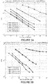
- Figures 2A, 2B , 3A, 3B shown simulation results that depict a variation in performance as a function of percentage of subcarriers that were not processed (also denoted as "erasures” in the legend of the plots), according to at least some embodiments.
- the following conditions were used for the 802.1 In WiFi standard.
- the conditions included modulation coding schemes 0, 2, 5, 7, with packet lengths of 4095 bytes, and a CMD channel model.
- Figures 2A, 2B , 3A, 3B also show results for the higher MCSs which have higher modulations and weaker codes (3/4, 2/3, 5/6). More specifically, Figure 2A is a plot of results of a simulation that shows the variation in performance as a function of percentage of subcarriers not processed (sub-carrier erasures) for a modulation and coding scheme MCS0 and rate 1 ⁇ 2 code, for an embodiment.
- Figure 2B is a plot of results of a simulation that shows the variation in performance as a function of percentage of subcarriers not processed (sub-carrier erasures) for a modulation and coding scheme MCS2 and rate 3 ⁇ 4 code, for an embodiment.
- Figure 3A is a plot of results of a simulation that shows the variation in performance as a function of percentage of subcarriers not processed (sub-carrier erasures) for a modulation and coding scheme MCS5 and rate 2/3 code, for an embodiment.
- Figure 3B is a plot of results of a simulation that shows the variation in performance as a function of percentage of subcarriers not processed (sub-carrier erasures) for a modulation and coding scheme MCS7 and rate 5/6 code, for an embodiment.
- the percentage of subcarriers that must be processed is higher than 50%, which is sufficient for MCS 0 (rate 1 ⁇ 2 code) at sufficiently high signal quality.
- subcarriers that were not processed in these simulations were chosen based on the subcarriers that had the lowest SNR. For instance, if the target was to not process 45% of the subcarriers, the 45% of subcarriers with the lowest SNR were chosen to not be processed.
- FIG. 4 shows a receiver portion of a transceiver 400 that includes selective processing of subcarriers of a received multicarrier signal based on streams of predicted least likelihood ratios (LLR(s)) of the received convolutional encoded multicarrier signal, according to an embodiment.
- LLR(s) predicted least likelihood ratios
- the set of predicted LLRs for each bit can be permuted or deinterleaved based on the knowledge of the interleaver (by, for example, a Create a Stream of Predicted LLRs block 443), thereby creating a stream of predicted LLRs (with each predicted LLR corresponding to the confidence level of each bit), which are de-interleaved at de-interleaving block 444.
- the percentage of subcarriers to not be processed is selected as joint function of SNR as well as avoiding a long run length of low predicted LLRs (relative to the distance properties of the code).
- processing block 470 selects subcarrier to process and/or subcarriers not to process based on the erased predicted LLRs.
- subcarriers are chosen to not be processed while avoiding a number of confidence levels in contiguous sequences of the de-interleaved predicted LLR sequence that are below a confidence threshold, that is above a run-length threshold.
- the signal is demodulated and decoded using the selected subcarriers to process as shown in Demodulate/Decode Selected Subset of Subcarriers block 180.
- bit node V 0 .
- This bit node is connected to 2 check nodes, C 1 and C 3 and hence bit node V 0 takes part in two parity checks and each of these checks involve three other bit nodes.
- other bit nodes connected to C 1 are V 1 , V 2 and V 5 and other bit nodes connected to C 3 are bit nodes V 3 , V 4 and V 6 .
- r Pr b n 0
- r , where r [ r 1 , r 2 ,... r N ] is the received vector.
- LLR Log-likelihood ratio
- the first term in ⁇ n is called the Intrinsic Information and represents the contribution from the channel observation impacted by the transmitted b n .
- the received sample which is used to determine the LLR for b n shall be denoted as r n or equivalently the n th channel observation.
- the second term represents the contributions from other channel observations apart from the n th observation and is called as the Extrinsic information.
- the reliability of a particular bit is influenced by both the intrinsic information which is a function of the channel reliability as well as information from other observations.
- the extrinsic information (second term) can be interpreted as sum of messages ( ⁇ ⁇ ( b i ) ) from all the check nodes involving code bit b n .
- the structure of the code and the decoding criterion explained in the previous section can be used to distinguish low confidence and high confidence nodes, or in other words less reliable (weaker) and more reliable nodes.
- nodes are classified based on the criterion that if a node having less intrinsic reliability is involved in multiple parity checks, then that node dominates the decision of the parity checks and secondly that node affects the extrinsic information of its neighboring bit nodes connected to a common check node. Such a bit node can be considered less reliable.
- An example of a procedure for node classification based on the above embodiment includes the following steps. First, for each check node, find the most unreliable bit node with which it is associated, that is, the bit node with the lowest magnitude of the intrinsic information. Second, for every bit node, all the check nodes to which it is connected to are listed. Third, for each of the above check nodes (listed in the second step), check if the most unreliable bit node associated with the check node happens to be the bit node in question (based on the first step). If so, increment a counter specific to that bit node by 1. Fourth, the second step and the third step are repeated for all bit nodes. Fifth, bit nodes are classified as unreliable or bad, which can be denoted as a "weak node", if their associated counter values are greater than a threshold ⁇ M 1 .
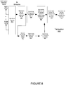
- Figure 6 shows a receiver portion of a transceiver 600 that includes selective processing of subcarriers of a received multicarrier signal based weak (unreliable) nodes of an LDPC decoder, according to an embodiment.
- This embodiment includes a tone de-mapper block 641 before the Create a Block of Predicted LLRs block 643.
- At least some embodiments include the erased predicted LLRs corresponding to subcarriers not to process (of processing block 445) being received by processing block 646 which identifies a number of weak (unreliable) nodes based on LDPC decoder knowledge.
- Processing block 647 determines whether the number of weak (unreliable) nodes exceeds a threshold. If the threshold is exceeded, the set of subcarriers erased is modified at processing block 448. That is, the set of predicted LLRs that correspond with the subcarriers not to process and erased is modified. The processing of blocks 445, 646 and 647 are repeated.
- an additional metric based counting of number of weak (unreliable) nodes is used to select which subcarriers should or should not be processed. Power consumption reduction by processing fewer nodes should be weighed against the possibility of increased iterations which increases power consumption.
- the receiver identifies the number of check nodes connected to an unrealiable bit node having a reliability below a reliability threshold.
- the receiver can select the subcarriers of the multi-carrier signal to perform receiver signal processing based on keeping the number of check nodes connected to a weak node having a reliability below a reliability threshold, less than a weak node number threshold.
- the reliability of a bit node is determined based on a channel estimate and noise estimate for a subcarrier corresponding to the bit node.
- Figure 7 shows a first transceiver 710, a second transceiver 720, and a MIMO transmission channel between the transceivers, according to an embodiment.
- the first transceiver 710 includes N antennas transmitting communication signals
- the second transceiver 720 includes M antennas receiving communications signals.
- the transmission channel between the first transceiver 710 and the second transceiver 720 can be characterized by an M X N channel matrix H.
- the transmission signals between the first transceiver 710 and the second transceiver 720 include multi-carrier modulation signals.
- Figure 8 shows a receiver portion of a multiple receiver transceiver that includes selective processing of subcarriers of a received multicarrier signal based on an orthogonality of a MIMO transmission channel of each of the subcarriers, according to an embodiment.
- synchronization is performed to determine the OFDM signal boundary on each of the received signals.
- a Synchronization Block 810 of a transceiver 800 in Figure 8 shows the process of synchronization where a packet is determined, for example, to be a valid OFDM signal and the symbol boundary of the OFDM signal is determined, for each of the plurality of received signals.
- a processing block 860 determines an orthogonality threshold based on a detected data rate and coding as determined by the Decode Preamble Signal Fields block 140 and a Detect Data Rate and Coding block 840.
- the subcarrier processing selection of each subcarrier is made based on the orthogonality determination of each subcarrier and the determined orthogonality threshold. More specifically, for an embodiment, subcarrier selection block 850 selects subcarriers not to process if the orthogonality of those subcarriers is less than the determined orthogonality threshold.
- the Select Subcarriers to Process and/or not to Process block 170 may functionally overlap the processing of block 850.
- the signal is demodulated and decoded using the selected subcarriers to process as shown in Demodulate/Decode Selected Subset of Subcarriers block 180 of Figure 8 .
- each subcarrier's channel matrix orthogonality or rank deficiency measures is used to choose subcarriers to drop from receiver processing.
- a receiver selects the subcarriers of the multi-carrier signal to perform receiver signal processing based an orthogonality of the channel matrix of each subcarrier being less than an orthogonality threshold. That is, the selected subcarriers are not processed if the orthogonality of the channel matrix of the subcarrier is less than the orthogonality threshold.
- the orthogonality is determined based on channel during a preamble of the received signal.
- the channel is estimated for each element of the channel matrix for every subcarrier.
- det(.) represents the determinant of the matrix and h i is the i th column of the matrix, H If H is singular, then the above metric is 0 and if the columns of H are completely orthogonal, the above metric equals 1. In general the value of the metric lies between 0 and 1. Therefore, a threshold can be selected between 0 and 1 (and possibly adapted).
- the percentage of subcarriers not processed is a function of the coding rate similar to the previously discussed case for the SISO (single input, single output) system.
- Another embodiment for selecting the subcarriers of the multi-carrier signal to perform receiver signal processing and which subcarriers of the multi-carrier signal not to perform receiver signal processing is based on a function of power consumed per processed subcarrier, and a probability of decoding error.
- the power consumption for receiver processing per subcarrier is estimated.
- a target number of subcarriers to be processed is determined.
- a minimum number of subcarriers that require processing is determined. If the minimum number is less than or equal to the target number, then the target number of subcarriers can be processed. If the minimum number of subcarriers is greater than the target number, then the minimum number of subcarriers would be processed by the receiver.
- the use of noise profile was described in relation to the choice of which subcarriers to process (and to not process) by the receiver. There is some penalty in receiver power consumption when the noise profile estimation is required.
- the savings in receiver power consumption is estimated based on the subcarriers chosen and the power per subcarrier saved in the blocks which are not processed. This savings should be weighed against the probability of slightly higher packet error rate which in turn increases the receiver power consumption as the packets in error will be required to be received again. Additionally, some power is consumed by requiring the software to track noise profile to help with interference/spurs monitoring. The power savings also will be dependent on whether the hardware design provides the ability to shut off portions of receiver blocks or simply benefits from no toggling of bits due to portions of receiver not being fed any actual signal with normal activity (the latter mode provides less savings than the former).
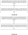
- Figure 9A shows flow charts that include steps of methods for selective processing of subcarriers of a received multicarrier signal, according to an embodiment.
- a first step 910 includes determining whether a signal quality of a received multi-carrier signal is better than a predetermined signal quality, wherein the predetermined signal quality is selected to ensure that a probability of error free decoding of the received signal is greater than a predetermined threshold.
- a second step 920 includes after determining that the signal quality of the received multi-carrier signal is better than the predetermined signal quality, determining which of subcarriers of the multi-carrier signal to perform receive signal processing based on a relative signal quality of each of the subcarriers.
- the second step includes determining which of subcarriers of the multi-carrier signal not to perform receive signal processing based on a relative signal quality of each of the subcarriers after determining that the signal quality of the received multi-carrier signal is better than the predetermined signal quality.
- the relative signal quality of each of the subcarriers is determined based on a comparison between a signal quality of each of the subcarriers relative to the predetermined signal quality.
- At least some embodiments additionally include determining a percentage of the subcarriers of the multi-carrier signal to perform receiver signal processing based on a function of a selected coding rate.
- At least some embodiments additionally include predicting a plurality of LLRs (log likelihood ratios) including predicting an LLR for each bit of a received symbol of each subcarrier based on the SNR of the subcarrier, wherein the LLR reflects a confidence level of the bit, generating a de-interleaved sequence comprising de-interleaving the plurality of LLRs, and selecting subcarriers of the multi-carrier signal to perform receiver signal processing based on avoiding a number of confidence levels in contiguous sequences of the de-interleaved sequence that are below a confidence threshold, that is above a run-length threshold.
- LLRs log likelihood ratios
- the received signal includes a transmit signal received though a transmission medium, wherein the transmit signal includes LDPC (low-density parity check) encoding.
- LDPC low-density parity check
- These embodiments further include specifying a parity check matrix based on the LDPC encoding, generating a set of parity check bits, comprising multiplying a block of n input bits by the parity check matrix, wherein the input bits and any information associated with the input bits are denoted as a variable nodes, and wherein the parity check bits and any information associated with the parity check bits are denoted as check nodes.
- these embodiments include identifying number of check nodes connected to a variable node having a reliability below a reliability threshold(also denoted "weak" node), and selecting the subcarriers of the multi-carrier signal to perform receiver signal processing based on keeping the number of weak nodes having a reliability below a reliability threshold less than a weak node number threshold.
- a reliability of a variable node is determined based on a channel estimate and noise estimate for a subcarrier corresponding to the variable node.
- the channel estimate is determined during the preamble.
- noise estimate are determined during the preamble or based on a priori knowledge.
- a receiver that receives the receive signal includes multiple receiver antennas, and wherein a channel between the receiver and a transmitter of the receive signal is characterized by a channel matrix for each subcarrier, and further comprising selecting the subcarriers of the multi-carrier signal to perform receiver signal processing based an orthogonality of the channel matrix of each subcarrier being less than a threshold (do not process if orthogonality is less than the threshold).
- the orthogonality is determined based on channel and noise estimated during a preamble of the received signal.
- each element of the channel matrix is determined during the preamble.
- Each element of the matrix represents the channel estimate of the channel between the transmit and receive antennas for the corresponding element in the matrix. Since a known signal is transmitted during the preamble, the MIMO channel matrix (that is, each element of the matrix) for each subcarrier can be estimated. Once the channel matrix is estimated, the expected receive signal can be estimated based on knowledge of the transmitted preamble signal and the channel estimate. For at least some embodiments, the expected receive signal is subtracted from the actual received signal to generate a noise power estimate for each receive chain for each subcarrier as illustrated in the equations below.
- the noise power is updated through the packet and also averaged across packets in time.
- the noise power will be a function of the analog gain setting, interference, and spurs. If sufficient data is collected over time, noise profiles can be developed for different gain settings and interference cases thereby allowing the recall of the relevant noise profile for a given packet rather than spending additional power computing noise profile during each received packet.
- selecting the subcarriers of the multi-carrier signal to perform receiver signal processing and which subcarriers of the multi-carrier signal not to perform receiver signal processing based on a function of power consumed per processed subcarrier, and a probability of decoding error. For instance, if the total subcarrier receiver processing consumes a total power of P R , and a fraction, ⁇ , of the subcarriers are processed, then the power savings may be (1- ⁇ )*P R during active processing.
- the receiver has to process more packets, namely (1+ ⁇ ) times the packets that would have been processed if all subcarriers were processed.
- the overall change in power consumption would be (1- ⁇ )*(1+ ⁇ )*P R .
- the receiver algorithm can be designed to choose ⁇ and ⁇ to minimize the overall power consumption given the constraint above.
- determining whether the signal quality of the received multi-carrier signal is better than the predetermined signal quality comprises measuring an SNR of the received signal during a preamble of the received signal, and comparing the measured SNR with an approximate required SNR.
- At least some embodiments further include determining a noise profile of a channel of the received signal, and selecting the subcarriers of the multi-carrier signal to perform receiver signal processing and which subcarriers of the multi-carrier signal not to perform receiver signal processing based on the noise profile.
- Another embodiment includes selecting the subcarriers of the multi-carrier signal to process or not to process in the presence of tonal interference which could affect several sub-carriers around the interfering tone.
- selection of sub-carriers for receive processing involves knowledge of the affected sub-carriers which is further dependent on the strength of the interference.
- the interference profile due to the tone is either estimated or known via prior measurements.
- the sub-carriers that are affected by the interference are given a higher priority in the "not to process" list when compared to the ones based on the lowest SNR.
- interference profile may be used interchangeably.
- Figure 10 shows a plot of the performance of MCS0 with an interfering tone at 4 MHz as a function of how many neighboring tones are erased, according to an embodiment.
- the Signal to Interference (SIR) power ratio is 0 dB. Note that declaring erasures on some sub-carriers turns out to be useful when compared to processing all the sub-carriers. It can be observed that the performance is improved by erasing out the closest sub-carrier and two of its adjacent neighbors (one on each side). In a case where the interfering tone is at higher power level compared to the signal, performance can be improved by erasing out more sub-carriers as shown in Figure 10 .
- Figure 11 is a plot of results of a simulation that shows the improvement in performance by using erasures in a neighborhood of the detected or known a priori interference for an SIR (Signal-to-Interference Ratio) of -5 dB, according to an embodiment.
- SIR Signal-to-Interference Ratio
- Figure 9B shows flow charts that include steps of methods for selective processing of subcarriers of a received multicarrier signal, according to another embodiment.
- a first step 911 includes determining whether a signal quality of a received multi-carrier signal is better than a predetermined signal quality, wherein the predetermined signal quality is selected to ensure that a probability of error free decoding of the received signal is greater than a predetermined threshold.
- a second step 921 includes after determining that the signal quality of the received multi-carrier signal is better than the predetermined signal quality, determining which subcarriers of the multi-carrier signal not to perform receive signal processing based on a relative signal quality of each of the subcarriers.
- Figure 12A shows flow charts that include steps of methods for selective processing of subcarriers of a received multicarrier signal, according to another embodiment.
- a first step 1210 includes determining whether a signal quality of a received multi-carrier signal is better than a predetermined signal quality, wherein the predetermined signal quality is selected to ensure that a probability of error free decoding of the received signal is greater than a predetermined threshold.
- a second step 1220 includes after determining that the signal quality of the received multi-carrier signal is better than the predetermined signal quality, determining which of subcarriers of the multi-carrier signal to perform receive signal processing based on a function of a selected coding rate.
- Figure 12B shows flow charts that include steps of methods for selective processing of subcarriers of a received multicarrier signal, according to another embodiment.
- a first step 1211 includes determining whether a signal quality of a received multi-carrier signal is better than a predetermined signal quality, wherein the predetermined signal quality is selected to ensure that a probability of error free decoding of the received signal is greater than a predetermined threshold.
- a second step 1221 includes after determining that the signal quality of the received multi-carrier signal is better than the predetermined signal quality, determining which subcarriers of the multi-carrier signal not to perform receive signal processing based on a function of a selected coding rate.
- the MAC layer of the receiver keeps track of packet error rate statistics over time and tracks whether there is a strong correlation (greater than a correlation threshold) between the predicted signal quality for a given packet (by the PHY layer) and whether the packet was decoded successfully or not. Additionally, for at least some embodiments, the MAC layer also determines whether the noise and interference statistics reported by the PHY are varying rapidly from packet to packet or have coherence times (coherence time can be based on duration over which statistics are correlated above a correlation threshold) on the order of tens of packets or longer.
- the MAC can enable the PHY to use selective subcarrier processing.
- the wireless environment is rapidly changing (that is, correlation of statistics of over short duration like a few packets is less than a threshold)
- the power consumption benefits may not be sufficient to warrant enabling of the selective subcarrier processing.
- the MAC statistics are also used to fine tune the thresholds used in selective subcarrier processing. In a highly volatile wireless environment (low correlation over short duration such as a few packets), more conservative signal quality thresholds may be require which effectively reduce the number of subcarriers that are not processed.
- signal quality thresholds can be adjusted so that percentage of subcarriers processed can approach the theoretical limits discussed previously based on SNR, type of code, and coding rate.
- the MAC estimates the channel type based on statistics over time and set thresholds for selective sub-carrier processing.
- determining which of subcarriers of the multi-carrier signal not to perform receive signal processing is further based on MAC layer information obtained over previously received packets.
- the predetermined signal quality is based on MAC layer information obtained over previously received packets.
- the MAC layer information includes, for example, the previously described channel statistics (such as, packet error rate statistics, noise interference statistics, channel type, coherence times), link quality, data rate, etc, across packets previously received on the current channel.
- a semiconductor intellectual property core such as a microprocessor core, or a portion thereof, fixed function circuitry, or configurable circuitry embodying the disclosure can be described in data stored on a machine readable medium. Such data can be in accordance with a Hardware Description Language (HDL), and may include Register Transfer Language (RTL) description data, for example. This descriptive data can be used to simulate, verify, and/or produce a specific implementation of the disclosure (for example, an integrated circuit, or a combination of integrated circuit(s) and discrete components).
- HDL Hardware Description Language
- RTL Register Transfer Language
- a signal quality determination processing block, and subcarrier selection processing can be implemented as separate processing (such as, signal quality determination processing block 130 or subcarrier selection processing block 170) from a processor, but such processing also could be implemented as a resource shared with other functional blocks, or a multiplier driven by decoded instructions from the processor.
Landscapes
- Engineering & Computer Science (AREA)
- Signal Processing (AREA)
- Computer Networks & Wireless Communication (AREA)
- Quality & Reliability (AREA)
- Error Detection And Correction (AREA)
- Detection And Prevention Of Errors In Transmission (AREA)
- Mobile Radio Communication Systems (AREA)
Abstract
Description
- The described embodiments relate generally to wireless communications. More particularly, the described embodiments relate to systems, methods and apparatuses for selectively processing sub-carriers of a received multi-carrier signal.
- The proliferation of mobile devices has driven the desire to reduce the power consumption of integrated circuits that support transmission and reception of wireless signals of the mobile devices. Typical implementations of OFDM (orthogonal frequency division multiplexing) receivers involve the demodulation/decoding of the received signal on all the subcarriers where the transmitter encoded information. Therefore, the receiver power consumption is impacted by the processing on all the subcarriers.
- It is desirable to have methods apparatuses, and systems for selectively processing sub-carriers of a received multi-carrier signal.
- An embodiment includes a receiver, wherein the receiver includes a receive chain and a controller. The receive chain is operative to receive a multi-carrier signal. The controller is operative to determine whether a signal quality of the received multi-carrier signal is better than a predetermined signal quality, wherein the predetermined signal quality is selected to ensure that a probability of error free decoding of the received signal is greater than a predetermined threshold, and determine which of subcarriers of the multicarrier signal to perform receive signal processing or which multicarrier signals not to perform receive signal processing based on a relative signal quality of each of the subcarriers after determining that the signal quality of the received multi-carrier signal is better than the predetermined signal quality.
- Another embodiment includes a method of selective subcarrier processing. The method includes determining whether a signal quality of a received multi-carrier signal is better than a predetermined signal quality, wherein the predetermined signal quality is selected to ensure that a probability of error free decoding of the received signal is greater than a predetermined threshold, and after determining that the signal quality of the received multi-carrier signal is better than the predetermined signal quality, determining which of subcarriers of the multi-carrier signal to either perform receive signal processing based on a relative signal quality of each of the subcarriers, or not to perform receive signal processing based on the relative signal quality of each of the subcarriers.
- Other aspects and advantages of the described embodiments will become apparent from the following detailed description, taken in conjunction with the accompanying drawings, illustrating by way of example the principles of the described embodiments.
-
-
Figure 1 shows a receiver portion of a transceiver that includes selective processing of subcarriers of a received multicarrier signal based on a signal quality of each subcarrier, according to an embodiment. -
Figure 2A is a plot of results of a simulation that shows the variation in performance as a function of percentage of subcarriers not processed (sub-carrier erasures) for a modulation and coding scheme MCS0 and rate ½ code, according to an embodiment. -
Figure 2B is a plot of results of a simulation that shows the variation in performance as a function of percentage of subcarriers not processed (sub-carrier erasures) for a modulation and coding scheme MCS2 and rate ¾ code, according to an embodiment. -
Figure 3A is a plot of results of a simulation that shows the variation in performance as a function of percentage of subcarriers not processed (sub-carrier erasures) for a modulation and coding scheme MCS5 andrate 2/3 code, according to an embodiment. -
Figure 3B is a plot of results of a simulation that shows the variation in performance as a function of percentage of subcarriers not processed (sub-carrier erasures) for a modulation and coding scheme MCS7 andrate 5/6 code, according to an embodiment. -
Figure 4 shows a receiver portion of a transceiver that includes selective processing of subcarriers of a received convolutional encoded multicarrier signal based on streams of predicted least likelihood ratios (LLR(s)) of the received multicarrier signal, according to an embodiment. -
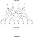
Figure 5 shows a tanner graph for a parity check matrix that can be utilized for partitioning blocks of n input bit predictive log likelihood ratios (LLRs) to a low-density parity check (LDPC) decoder into a low confidence subset or a high confidence, according to an embodiment. -
Figure 6 shows a receiver portion of a transceiver that includes selective processing of subcarriers of a received LDPC encoded multicarrier signal based weak nodes of an LDPC decoder, according to an embodiment. -
Figure 7 shows a first transceiver, a second transceiver, and a MIMO transmission channel between the transceivers, according to an embodiment. -
Figure 8 shows a receiver portion of a multiple receiver transceiver that includes selective processing of subcarriers of a received multicarrier signal based on an orthogonality of a MIMO transmission channel of each of the subcarriers, according to an embodiment. -
Figure 9A shows a flow chart that includes steps of methods for selective processing of subcarriers of a received multicarrier signal, according to an embodiment. -
Figure 9B show a flow chart that includes steps of methods for selective processing of subcarriers of a received multicarrier signal, according to another embodiment. -
Figure 10 is a plot of results of a simulation that shows the improvement in performance by using erasures in a neighborhood of the detected or known a priori interference for an SIR (Signal-to-Interference Ratio) of 0 dB, according to an embodiment. -
Figure 11 is a plot of results of a simulation that shows the improvement in performance by using erasures in a neighborhood of the detected or known a priori interference for an SIR (Signal-to-Interference Ratio) of -5 dB, according to an embodiment. -
Figure 12A shows a flow chart that includes steps of methods for selective processing of subcarriers of a received multicarrier signal, according to another embodiment. -
Figure 12B shows a flow chart that includes steps of methods for selective processing of subcarriers of a received multicarrier signal, according to another embodiment. - The embodiments described include methods, apparatuses, and systems for selectively processing sub-carriers of a received multi-carrier signal. The selective subcarrier processing save power as compared to receiver systems that do not include selective subcarrier processing. The described embodiments include identifying when selective subcarrier processing should be considered, and further, various methods of implementing the selective processing of the subcarriers.
- For an embodiment, the transmission signals between a first transceiver and a second transceiver include multi-carrier modulation signals. Multi-carrier modulation (MCM) is a method of transmitting data by splitting it into several components, and sending each of these components over separate carrier signals. The individual carriers have narrow bandwidth, but the composite signal can have broad bandwidth. The advantages of MCM include relative immunity to fading caused by transmission over more than one path at a time (multipath fading), less susceptibility than single-carrier systems to interference caused by impulse noise, and enhanced immunity to inter-symbol interference.
- An exemplary form of MCM includes orthogonal frequency-division multiplexing (OFDM). OFDM is essentially identical to coded OFDM (COFDM) and discrete multi-tone modulation (DMT), and is a frequency-division multiplexing (FDM) scheme used as a digital multi-carrier modulation method. The primary advantage of OFDM over single-carrier schemes is its ability to cope with severe channel conditions (for example, narrowband interference and frequency-selective fading due to multipath) without complex equalization filters. Channel equalization is simplified because OFDM may be viewed as using many slowly modulated narrowband signals rather than one rapidly modulated wideband signal. The low symbol rate makes the use of a guard interval between symbols affordable, making it possible to eliminate intersymbol interference (ISI) and utilize echoes and time-spreading to achieve a diversity gain, that is, a signal-to-noise ratio improvement.
- At least some of the described embodiments include identifying when to implement selective subcarrier processing.
-
Figure 1 shows a receiver portion of a transceiver that includes selective processing of subcarriers of a received multicarrier signal based on a signal quality of each subcarrier, according to an embodiment. Upon receiving a signal, synchronization is performed to determine an OFDM signal boundary on the received signal. For example, aSynchronization Block 110 of atransceiver 100 inFigure 1 shows the process of synchronization where a packet is determined, for example, to be a valid OFDM signal and the symbol boundary of the OFDM signal is determined. Next, based on knowledge of the transmitted OFDM symbols, the receiver estimates the channel and noise for the received signal for each subcarrier as shown in a Channel andNoise Estimator block 120 ofFigure 1 . Using the channel and noise, an SNR (signal to noise ratio) per subcarrier and an overall average SNR for the received signal can be determined. SNR is one measure of signal quality. As shown in a DetermineSignal Quality block 130 ofFigure 1 , a measure of signal quality (including, for example, SNR) may be used to assess the quality of the received signal. - While the processing blocks of
Figure 1 are shown separately, it is to be understood that this is for ease of description, and that the functional processing can be represented and implemented in alternate forms. - For at least some embodiments, following channel and noise estimation, the receiver decodes subsequent OFDM symbols during the preamble of the OFDM symbols to determine information about the transmitted signal characteristics for the payload such as modulation, coding rate, and packet length as shown in a Decode Preamble
Signal Fields block 140 and a Detect Data Rate andCoding block 150 ofFigure 1 . Additionally, for at least some embodiments, based on the preamble signal processing, a signal quality threshold is determined for the received signal, which is included, for example, in a Determine SignalQuality Threshold block 160 ofFigure 1 . For at least some embodiments, the signal quality is compared against a predetermined or the previously described signal quality threshold determined based on preamble signal processing. For an embodiment, the signal quality threshold is selected to ensure that a received signal with the stated signal characteristics (that is, modulation, coding rate, packet length) could be decoded error free with probability greater than a predetermined error free probability threshold if the predetermined signal quality threshold is exceeded. If the signal quality of the received signal exceeds this predetermined signal quality threshold, then selective subcarrier processing is implemented which includes choosing a subset of all subcarriers to be processed by the receiver in order to decode the received signal. A common measure of signal quality is the Signal to Noise Ratio (SNR) of the received signal. The calculation of SNR along with the selection of a predetermined signal quality or SNR threshold is detailed below. - For an embodiment, a lookup table is then used to determine the approximate required SNR for the data rate of the current packet being received. If the average SNR of the signal is determined to be some threshold above the required SNR in the lookup table for the data rate, then selective subcarrier processing can be considered.
- That is, for at least some embodiments, the difference between the average SNR and the required SNR must above an SNR threshold. For at least some embodiments, factors that affect the choice of the SNR threshold include the error in the SNR measurement, the sensitivity of the PER (packet error rate) to the SNR (that is, PER vs SNR slope), the frequency selectivity of the channel, the noise profile across the channel, and/or the coding rate.
- Depending on the channel and noise estimation algorithms and also the number of OFDM symbols used to estimate the SNR, the accuracy of the SNR estimate is impacted. For a relatively inaccurate SNR estimate, a higher threshold may be necessary to ensure that subcarriers are not incorrectly dropped from processing. For an embodiment, the error of the SNR measurement is also weighed against the sensitivity of the PER to the change in SNR. For instance, if the PER changes substantially versus a small change in SNR for a particular data rate and coding rate, then the threshold needs to be higher to ensure that if subcarriers are dropped from processing, there is adequate margin to properly decode the signal.
- For at least some embodiments, the channel type impacts the SNR required to properly decode a signal. Typically, LOS (line-of-sight) channels can decode a received signal for a particular data rate at a lower SNR than an NLOS (non-line-of-sight) channel. Various methods can be used in the preamble processing like channel estimation and associated frequency selectivity to determine whether the channel is LOS or NLOS. For LOS, for an embodiment, a lower threshold is used in comparison with NLOS. Alternatively, for an embodiment, multiple lookup tables are available, one for LOS and one for NLOS in determining the required SNR (and hence the SNR threshold could be the same for both cases). For at least some embodiments, the channel type (LOS or NLOS) is determined by examining the magnitude of correlation peaks relative to the signal power during synchronization. Typically, LOS channels exhibit higher correlation peaks than NLOS or more dispersive channels.
- For at least some embodiments, another method that is used to estimate the channel type includes measuring the frequency selectivity of the channel. For LOS channels, the channel profile will not exhibit as much frequency selectivity as NLOS channels. One possible measure includes counting the number of subcarriers whose power is within some threshold (for example, 3dB) of the mean power of the channel. When the number of such subcarriers is a high percentage, then the channel is likely LOS.
- In addition to data rate, for at least some embodiments, a coding type (for example, BCC (binary convolutional code), LDPC (low-density parity check)) plays a role in the required SNR too. For an embodiment, the lookup table has the required SNR for different coding schemes.
- For at least some embodiments, even in cases where the average SNR does not exceed the desired SNR by the threshold, the noise profile is shaped due to interference/spurs. In such cases, a priori information (e.g. from previous packets) or preamble processing is used to determine that portions of the spectrum where the noise is high may not be suitable for decoding. For at least some embodiments, for a noise spectrum that is shaped due to spurs/interference, a higher SNR threshold is used to trigger selective subcarrier processing or the method of choosing which and number of subcarriers to drop (i.e. not process) is modified due to the presence of colored noise.
- At least some embodiments include using one or more of several possible metrics and selection criteria based on these metrics that are used to decide which subcarriers should be processed during the decoding process and which subcarriers should not be processed to save power. The idea is to skip processing those subcarriers which do not preclude the successful decoding a received signal as shown in a Select Subcarriers to Process and/or not to Process block 170 in
Figure 1 . Following the selection of subcarriers, the signal is demodulated and decoded using the selected subcarriers to process as shown in a Demodulate/Decode Selected Subset of Subcarriers block 180 ofFigure 1 . - For example, for at least some embodiments, the lowest SNR subcarriers are excluded from receiver processing. For at least some embodiments, the number of lowest SNR subcarriers is chosen as a function of the coding rate. Specifically, a certain percentage of subcarriers as a function of the coding rate are used as a target for not being decoded. For example, for an embodiment, if the coding rate is ½, then the maximum possible subcarriers that are not processed is 50%. However, if 50% of the subcarriers are not processed, the remainder 50% should have sufficiently high SNRs that the removal of the benefit of coding (by not processing half the subcarriers) does not noticeably reduce the likelihood of successful decoding of the signal. In practice, there is some margin chosen such that the percent of subcarriers not processed in this example would be less than 50%. The actual amount less than 50% that would not be processed depend on the SNRs of the subcarriers which are being processed.
- In general, for a signal with coding rate r, the fraction of subcarriers that may not be processed should be less than (1-r). As mentioned above, for at least some embodiments a margin shall be chosen which sets the actual fraction of subcarriers to not be processed as γ*(1-r), where γ < 1.
-
Figures 2A, 2B ,3A, 3B shown simulation results that depict a variation in performance as a function of percentage of subcarriers that were not processed (also denoted as "erasures" in the legend of the plots), according to at least some embodiments. For the simulations, the following conditions were used for the 802.1 In WiFi standard. The conditions includedmodulation coding schemes - For
MCS 0, if the SNR > 8 dB, then even with 45% erasures, 10% PER can be achieved. The coding rate is 1/2 for this MCS. Therefore, the fraction of subcarriers that may not be processed is (1-r) = ½. Thus, if the percentage of subcarriers processed is more than 50% (or equivalently if the percentage of subcarriers not processed is less than 50%), successful decoding is possible at sufficiently high SNR or signal quality. -
Figures 2A, 2B ,3A, 3B also show results for the higher MCSs which have higher modulations and weaker codes (3/4, 2/3, 5/6). More specifically,Figure 2A is a plot of results of a simulation that shows the variation in performance as a function of percentage of subcarriers not processed (sub-carrier erasures) for a modulation and coding scheme MCS0 and rate ½ code, for an embodiment.Figure 2B is a plot of results of a simulation that shows the variation in performance as a function of percentage of subcarriers not processed (sub-carrier erasures) for a modulation and coding scheme MCS2 and rate ¾ code, for an embodiment.Figure 3A is a plot of results of a simulation that shows the variation in performance as a function of percentage of subcarriers not processed (sub-carrier erasures) for a modulation and coding scheme MCS5 andrate 2/3 code, for an embodiment.Figure 3B is a plot of results of a simulation that shows the variation in performance as a function of percentage of subcarriers not processed (sub-carrier erasures) for a modulation and coding scheme MCS7 andrate 5/6 code, for an embodiment. - Due to the weaker codes, the percentage of subcarriers that must be processed is higher than 50%, which is sufficient for MCS 0 (rate ½ code) at sufficiently high signal quality.
- Note that the subcarriers that were not processed in these simulations were chosen based on the subcarriers that had the lowest SNR. For instance, if the target was to not process 45% of the subcarriers, the 45% of subcarriers with the lowest SNR were chosen to not be processed.
- Other methods besides just choosing the lowest SNR subcarriers may be used that factor in the coding scheme that was applied by the transmitter for the received signal. Specifically, approaches to choosing subcarriers to not process are described below for Binary convolutional coding and LDPC.
-
Figure 4 shows a receiver portion of atransceiver 400 that includes selective processing of subcarriers of a received multicarrier signal based on streams of predicted least likelihood ratios (LLR(s)) of the received convolutional encoded multicarrier signal, according to an embodiment. - For the case of convolutional encoding, for an embodiment, the LLRs are predicted based on the SNR for each subcarrier (for example, by a SNR to a Predicted LLR block 442), knowledge of constellation mapping and the interleaver. For an embodiment, the confidence level of each bit (or equivalently the predicted mean LLR) is obtained as a function of the SNR and constellation mapper. The set of predicted LLRs for each bit can be permuted or deinterleaved based on the knowledge of the interleaver (by, for example, a Create a Stream of Predicted LLRs block 443), thereby creating a stream of predicted LLRs (with each predicted LLR corresponding to the confidence level of each bit), which are de-interleaved at
de-interleaving block 444. For an embodiment, the percentage of subcarriers to not be processed is selected as joint function of SNR as well as avoiding a long run length of low predicted LLRs (relative to the distance properties of the code). - For an embodiment, a
subcarrier selection block 449 selects subcarriers not to process based on the SNR of the subcarrier and/or a coding rate. For an embodiment, predicted LLRs that correspond with the subcarriers not to process are erased at block 445. For at least some embodiments, the erasure of the LLR simply means to assign the lowest possible confidence level which is equivalent to stating that the probability of the bit being a 1 is equal to the probability of the bit being a 0 (that is, a 50/50 chance of bit being a 1 or 0). The erasures serve the purpose of notifying the decoder that no useful information is available about the likely value of the bit - which in this case is due to the fact that the corresponding subcarrier to which the bit was mapped is not being processed. At block 446, a maximum run length of predicted LLRs (that is, number of consecutive predicted LLRs) is determined by comparing each of the predicted LLRs with a threshold. Atprocessing block 447, the determined maximum run length of predicted LLRs that are below the threshold is compared with a run length threshold. If the maximum run length is greater than the run length threshold, the set of subcarriers erased is modified atprocessing block 448. That is, the set of predicted LLRs that correspond with the subcarriers not to process and erased is modified - more specifically, reduced in number. For an embodiment, the reduction or modification includes removing from the "erased" list those predicted LLRs which had the highest LLRs/confidence levels before being erased. Note that by definition, the erased LLRs have predicted LLRs less than or equal to the threshold because the erased LLRs are set to the lowest possible LLR or confidence level. The processing ofblocks 445, 446 and 447 are repeated. - If at
processing block 447 the determined maximum run length of predicted LLRs that are below the threshold is determined to be less than the run length threshold, processing block 470 selects subcarrier to process and/or subcarriers not to process based on the erased predicted LLRs. - For at least some embodiments, subcarriers are chosen to not be processed while avoiding a number of confidence levels in contiguous sequences of the de-interleaved predicted LLR sequence that are below a confidence threshold, that is above a run-length threshold.
- Following the selection of subcarriers, the signal is demodulated and decoded using the selected subcarriers to process as shown in Demodulate/Decode Selected Subset of
Subcarriers block 180. - A better understanding of the described embodiments that utilize predictive LLRs and metrics for node classification in the LDPC decoder can be obtained by closely looking at the structure of the code and the decoding criterion.
Figure 5 shows a tanner graph for a parity check matrix that can be utilized for partitioning blocks of n input bit predictive LLRs to an LDPC decoder into a low confidence subset or a high confidence subset, according to an embodiment. This Tanner graph provides a graphical representation of an (8, 4) code. In this graph, the nodes of the graph are separated into two distinctive sets, and edges connect nodes of two different types. The two types of nodes a Tanner graph addresses are variable nodes (bit nodes or V-nodes) and check nodes (or C-nodes). Check node, Ci is connected to variable node Vj if the element hij of the parity check matrix H is a 1.Figure 5 shows the tanner graph representation for the above parity check matrix, given by H.
- Consider the perspective of the graph from bit node, V 0. This bit node is connected to 2 check nodes, C 1 and C 3 and hence bit node V 0 takes part in two parity checks and each of these checks involve three other bit nodes. For example, other bit nodes connected to C 1 are V1 , V 2 and V 5 and other bit nodes connected to C 3 are bit nodes V 3, V 4 and V 6.
- The detector that minimizes the probability of error for the n -th bit, bn calculates a posterior Log-likelihood ratio (LLR), λn given by,

- The detector decides b̂n = 1 if λn ≥ 0 and b̂n = 0 otherwise. The above can be simplified as

- The first term in λn is called the Intrinsic Information and represents the contribution from the channel observation impacted by the transmitted bn. For convenience, the received sample which is used to determine the LLR for bn shall be denoted as rn or equivalently the nth channel observation. The second term represents the contributions from other channel observations apart from the nth observation and is called as the Extrinsic information. Hence the reliability of a particular bit is influenced by both the intrinsic information which is a function of the channel reliability as well as information from other observations.
- Assuming that the code bit bn is involved in exactly j parity checks, numbered 1 through j and say each of the j check nodes involve k-1 other bits.
- Letting b i = [b i,2,...bi,k ] denote the set of code bits involved in the ith (i=1...j) parity check excluding the code bit, bn, and letting Φ(b) denote the parity of a set of bits, b . Then, the j parity check constraints involving code bit bn ensure that bn = Φ(b i ), ∀i = 1....j. Hence, the result is:

- Assuming that the code is cycle free, the vectors, b i ,i = 1..j are conditionally independent given as {r i≠n }. Hence, the result is:

- In the above, the extrinsic information (second term) can be interpreted as sum of messages ( λ Φ(b i )) from all the check nodes involving code bit bn .
- Using the min-sum approximation, the each of the extrinsic information can be approximated as,


- The structure of the code and the decoding criterion explained in the previous section can be used to distinguish low confidence and high confidence nodes, or in other words less reliable (weaker) and more reliable nodes.
- For at least some embodiments, nodes are classified based on the criterion that if a node having less intrinsic reliability is involved in multiple parity checks, then that node dominates the decision of the parity checks and secondly that node affects the extrinsic information of its neighboring bit nodes connected to a common check node. Such a bit node can be considered less reliable.
- An example of a procedure for node classification based on the above embodiment includes the following steps. First, for each check node, find the most unreliable bit node with which it is associated, that is, the bit node with the lowest magnitude of the intrinsic information. Second, for every bit node, all the check nodes to which it is connected to are listed. Third, for each of the above check nodes (listed in the second step), check if the most unreliable bit node associated with the check node happens to be the bit node in question (based on the first step). If so, increment a counter specific to that bit node by 1. Fourth, the second step and the third step are repeated for all bit nodes. Fifth, bit nodes are classified as unreliable or bad, which can be denoted as a "weak node", if their associated counter values are greater than a threshold ΓM
1 . -
Figure 6 shows a receiver portion of atransceiver 600 that includes selective processing of subcarriers of a received multicarrier signal based weak (unreliable) nodes of an LDPC decoder, according to an embodiment. This embodiment includes a tonede-mapper block 641 before the Create a Block of PredictedLLRs block 643. - Further, at least some embodiments include the erased predicted LLRs corresponding to subcarriers not to process (of processing block 445) being received by processing
block 646 which identifies a number of weak (unreliable) nodes based on LDPC decoder knowledge.Processing block 647 determines whether the number of weak (unreliable) nodes exceeds a threshold. If the threshold is exceeded, the set of subcarriers erased is modified atprocessing block 448. That is, the set of predicted LLRs that correspond with the subcarriers not to process and erased is modified. The processing ofblocks - If
processing block 647 determines that the number of weak (unreliable) nodes is less than the threshold,processing block 170 selects subcarrier to process and/or subcarriers not to process based on the erased predicted LLRs. - For at least some embodiments, for the case of LDPC decoding, in addition to SNR based subcarrier selection, an additional metric based counting of number of weak (unreliable) nodes is used to select which subcarriers should or should not be processed. Power consumption reduction by processing fewer nodes should be weighed against the possibility of increased iterations which increases power consumption.
- Specifically, for an embodiment, the receiver identifies the number of check nodes connected to an unrealiable bit node having a reliability below a reliability threshold. Next, the receiver can select the subcarriers of the multi-carrier signal to perform receiver signal processing based on keeping the number of check nodes connected to a weak node having a reliability below a reliability threshold, less than a weak node number threshold. For an embodiment, the reliability of a bit node is determined based on a channel estimate and noise estimate for a subcarrier corresponding to the bit node.
-
Figure 7 shows afirst transceiver 710, asecond transceiver 720, and a MIMO transmission channel between the transceivers, according to an embodiment. As shown, thefirst transceiver 710 includes N antennas transmitting communication signals, and thesecond transceiver 720 includes M antennas receiving communications signals. Accordingly, the transmission channel between thefirst transceiver 710 and thesecond transceiver 720 can be characterized by an M X N channel matrix H. For an embodiment, the transmission signals between thefirst transceiver 710 and thesecond transceiver 720 include multi-carrier modulation signals. - An embodiment includes obtaining a channel matrix H per sub-carrier of a multi-carrier signal. For an embodiment, the channel matrix is determined at the receiver, and communicated back to the transmitter. However, for another embodiment, the channel matrix is determined at the transmitter. That is, by assuming reciprocity of the transmission channel, signals received by the transmitting transceiver from the receiving transmitter can be used to determine the channel matrix H.
-
Figure 8 shows a receiver portion of a multiple receiver transceiver that includes selective processing of subcarriers of a received multicarrier signal based on an orthogonality of a MIMO transmission channel of each of the subcarriers, according to an embodiment. Upon receiving a multiple signals, synchronization is performed to determine the OFDM signal boundary on each of the received signals. For example, aSynchronization Block 810 of atransceiver 800 inFigure 8 shows the process of synchronization where a packet is determined, for example, to be a valid OFDM signal and the symbol boundary of the OFDM signal is determined, for each of the plurality of received signals. - For at least some embodiments, a processing block 820 determines the channel matrix of each subcarrier the plurality of receive signals. A processing block 830 determines the orthogonality of the channel matrix.
- A
processing block 860 determines an orthogonality threshold based on a detected data rate and coding as determined by the Decode Preamble Signal Fields block 140 and a Detect Data Rate andCoding block 840. - The subcarrier processing selection of each subcarrier is made based on the orthogonality determination of each subcarrier and the determined orthogonality threshold. More specifically, for an embodiment, subcarrier selection block 850 selects subcarriers not to process if the orthogonality of those subcarriers is less than the determined orthogonality threshold. The Select Subcarriers to Process and/or not to Process block 170 may functionally overlap the processing of block 850. Following the selection of subcarriers, the signal is demodulated and decoded using the selected subcarriers to process as shown in Demodulate/Decode Selected Subset of Subcarriers block 180 of
Figure 8 . - For an embodiment, for MIMO receivers, in addition to SNR metrics, each subcarrier's channel matrix orthogonality or rank deficiency measures is used to choose subcarriers to drop from receiver processing. For example, for an embodiment, a receiver selects the subcarriers of the multi-carrier signal to perform receiver signal processing based an orthogonality of the channel matrix of each subcarrier being less than an orthogonality threshold. That is, the selected subcarriers are not processed if the orthogonality of the channel matrix of the subcarrier is less than the orthogonality threshold.
- For an embodiment, the orthogonality is determined based on channel during a preamble of the received signal. The channel is estimated for each element of the channel matrix for every subcarrier. For at least some embodiments, a metric that is used to measure orthogonality is the orthogonality deficiency (o.d) metric. This metric, od is defined as

- In the above, det(.) represents the determinant of the matrix and hi is the ith column of the matrix, H If H is singular, then the above metric is 0 and if the columns of H are completely orthogonal, the above metric equals 1. In general the value of the metric lies between 0 and 1. Therefore, a threshold can be selected between 0 and 1 (and possibly adapted). For an embodiment, the percentage of subcarriers not processed is a function of the coding rate similar to the previously discussed case for the SISO (single input, single output) system.
- Another embodiment for selecting the subcarriers of the multi-carrier signal to perform receiver signal processing and which subcarriers of the multi-carrier signal not to perform receiver signal processing is based on a function of power consumed per processed subcarrier, and a probability of decoding error. For an embodiment, the power consumption for receiver processing per subcarrier is estimated. For an embodiment, given a target power consumption, a target number of subcarriers to be processed is determined. Additionally, based on a desired probability of decoding error, a minimum number of subcarriers that require processing is determined. If the minimum number is less than or equal to the target number, then the target number of subcarriers can be processed. If the minimum number of subcarriers is greater than the target number, then the minimum number of subcarriers would be processed by the receiver.
- Previously, the use of noise profile was described in relation to the choice of which subcarriers to process (and to not process) by the receiver. There is some penalty in receiver power consumption when the noise profile estimation is required. As mentioned earlier, for an embodiment, the savings in receiver power consumption is estimated based on the subcarriers chosen and the power per subcarrier saved in the blocks which are not processed. This savings should be weighed against the probability of slightly higher packet error rate which in turn increases the receiver power consumption as the packets in error will be required to be received again. Additionally, some power is consumed by requiring the software to track noise profile to help with interference/spurs monitoring. The power savings also will be dependent on whether the hardware design provides the ability to shut off portions of receiver blocks or simply benefits from no toggling of bits due to portions of receiver not being fed any actual signal with normal activity (the latter mode provides less savings than the former).
-
Figure 9A shows flow charts that include steps of methods for selective processing of subcarriers of a received multicarrier signal, according to an embodiment. Afirst step 910 includes determining whether a signal quality of a received multi-carrier signal is better than a predetermined signal quality, wherein the predetermined signal quality is selected to ensure that a probability of error free decoding of the received signal is greater than a predetermined threshold. Asecond step 920 includes after determining that the signal quality of the received multi-carrier signal is better than the predetermined signal quality, determining which of subcarriers of the multi-carrier signal to perform receive signal processing based on a relative signal quality of each of the subcarriers. For an alternate embodiment, the second step includes determining which of subcarriers of the multi-carrier signal not to perform receive signal processing based on a relative signal quality of each of the subcarriers after determining that the signal quality of the received multi-carrier signal is better than the predetermined signal quality. - For at least some embodiments, the relative signal quality of each of the subcarriers is determined based on a comparison between a signal quality of each of the subcarriers relative to the predetermined signal quality.
- At least some embodiments additionally include determining a percentage of the subcarriers of the multi-carrier signal to perform receiver signal processing based on a function of a selected coding rate.
- At least some embodiments additionally include predicting a plurality of LLRs (log likelihood ratios) including predicting an LLR for each bit of a received symbol of each subcarrier based on the SNR of the subcarrier, wherein the LLR reflects a confidence level of the bit, generating a de-interleaved sequence comprising de-interleaving the plurality of LLRs, and selecting subcarriers of the multi-carrier signal to perform receiver signal processing based on avoiding a number of confidence levels in contiguous sequences of the de-interleaved sequence that are below a confidence threshold, that is above a run-length threshold.
- For at least some embodiments, the received signal includes a transmit signal received though a transmission medium, wherein the transmit signal includes LDPC (low-density parity check) encoding. These embodiments further include specifying a parity check matrix based on the LDPC encoding, generating a set of parity check bits, comprising multiplying a block of n input bits by the parity check matrix, wherein the input bits and any information associated with the input bits are denoted as a variable nodes, and wherein the parity check bits and any information associated with the parity check bits are denoted as check nodes. Further, these embodiments include identifying number of check nodes connected to a variable node having a reliability below a reliability threshold(also denoted "weak" node), and selecting the subcarriers of the multi-carrier signal to perform receiver signal processing based on keeping the number of weak nodes having a reliability below a reliability threshold less than a weak node number threshold. For at least some embodiments, a reliability of a variable node is determined based on a channel estimate and noise estimate for a subcarrier corresponding to the variable node.
- For at least some embodiments, the channel estimate is determined during the preamble. For at least some embodiments, noise estimate are determined during the preamble or based on a priori knowledge.
- For at least some embodiments, a receiver that receives the receive signal includes multiple receiver antennas, and wherein a channel between the receiver and a transmitter of the receive signal is characterized by a channel matrix for each subcarrier, and further comprising selecting the subcarriers of the multi-carrier signal to perform receiver signal processing based an orthogonality of the channel matrix of each subcarrier being less than a threshold (do not process if orthogonality is less than the threshold). For at least some embodiments, the orthogonality is determined based on channel and noise estimated during a preamble of the received signal.
- For at least some embodiments, each element of the channel matrix is determined during the preamble. Each element of the matrix represents the channel estimate of the channel between the transmit and receive antennas for the corresponding element in the matrix. Since a known signal is transmitted during the preamble, the MIMO channel matrix (that is, each element of the matrix) for each subcarrier can be estimated. Once the channel matrix is estimated, the expected receive signal can be estimated based on knowledge of the transmitted preamble signal and the channel estimate. For at least some embodiments, the expected receive signal is subtracted from the actual received signal to generate a noise power estimate for each receive chain for each subcarrier as illustrated in the equations below.
- The actual received signal can be expressed as:

- where k is the subcarrier index,
- yk is an Mx1 vector representing the received signal for subcarrier k across the M receive chains,
- Hk is the MxN channel matrix for subcarrier k,
- xk is the Nx1 transmit vector across the N transmit chains for subcarrier k,
- nk is the Mx1 receive noise vector across the N receive chains for subcarrier k The noise power per receive chain per subcarrier may be estimated as follows:

- where E denotes expectation or average of the quantity over many symbols,
- Ĥ k is the estimated channel matrix for subcarrier k,
- x̂k is the estimated transmitted symbol vector for subcarrier k (or the a priori known transmit symbol),
- σk 2 is the estimated noise power vector per receive chain per subcarrier
- It should be noted that for at least some embodiments, the noise power is updated through the packet and also averaged across packets in time. Typically, the noise power will be a function of the analog gain setting, interference, and spurs. If sufficient data is collected over time, noise profiles can be developed for different gain settings and interference cases thereby allowing the recall of the relevant noise profile for a given packet rather than spending additional power computing noise profile during each received packet.
- For at least some embodiments, selecting the subcarriers of the multi-carrier signal to perform receiver signal processing and which subcarriers of the multi-carrier signal not to perform receiver signal processing based on a function of power consumed per processed subcarrier, and a probability of decoding error. For instance, if the total subcarrier receiver processing consumes a total power of PR, and a fraction, γ, of the subcarriers are processed, then the power savings may be (1-γ)*PR during active processing. If using the subset of subcarriers for receiver processing, increases the likelihood of decoding error by a fraction α - meaning that a higher fraction of the packets have to be retransmitted by the transmitter and therefore, the receiver has to process more packets, namely (1+α) times the packets that would have been processed if all subcarriers were processed. Thus, the overall change in power consumption would be (1-γ)*(1+α)*PR.
- Assuming that the overall duty cycle of active reception or fraction of time that the receiver is receiving packets (based on typical traffic patterns) is Δ, and the overall receiver target power consumption is P T, then the following constraint should be satisfied:

- For at least some embodiments, determining whether the signal quality of the received multi-carrier signal is better than the predetermined signal quality comprises measuring an SNR of the received signal during a preamble of the received signal, and comparing the measured SNR with an approximate required SNR.
- At least some embodiments further include determine whether the received signal was received through a LOS channel or a NLOS channel, and selecting the approximate required SNR based on whether a LOS channel or NLOS channel.
- At least some embodiments further include determining a noise profile of a channel of the received signal, and selecting the subcarriers of the multi-carrier signal to perform receiver signal processing and which subcarriers of the multi-carrier signal not to perform receiver signal processing based on the noise profile.
- Another embodiment includes selecting the subcarriers of the multi-carrier signal to process or not to process in the presence of tonal interference which could affect several sub-carriers around the interfering tone. In such a scenario, selection of sub-carriers for receive processing involves knowledge of the affected sub-carriers which is further dependent on the strength of the interference. In many cases, the interference profile due to the tone is either estimated or known via prior measurements. In such a case, for an embodiment, the sub-carriers that are affected by the interference are given a higher priority in the "not to process" list when compared to the ones based on the lowest SNR. However, if the number of sub-carriers affected by interference is small and there is more room for other sub-carriers not to be processed, then the low SNR sub-carriers are added to the "not to process list". An added advantage of knowing the interference profile is that SNR does not have to be explicitly estimated on the affected sub-carriers, thereby reducing processing complexity. It is to be understood that for at least some embodiments the terms interference profile and noise profile may be used interchangeably.
-
Figure 10 shows a plot of the performance of MCS0 with an interfering tone at 4 MHz as a function of how many neighboring tones are erased, according to an embodiment. The Signal to Interference (SIR) power ratio is 0 dB. Note that declaring erasures on some sub-carriers turns out to be useful when compared to processing all the sub-carriers. It can be observed that the performance is improved by erasing out the closest sub-carrier and two of its adjacent neighbors (one on each side). In a case where the interfering tone is at higher power level compared to the signal, performance can be improved by erasing out more sub-carriers as shown inFigure 10 .Figure 11 is a plot of results of a simulation that shows the improvement in performance by using erasures in a neighborhood of the detected or known a priori interference for an SIR (Signal-to-Interference Ratio) of -5 dB, according to an embodiment. -
Figure 9B shows flow charts that include steps of methods for selective processing of subcarriers of a received multicarrier signal, according to another embodiment. Afirst step 911 includes determining whether a signal quality of a received multi-carrier signal is better than a predetermined signal quality, wherein the predetermined signal quality is selected to ensure that a probability of error free decoding of the received signal is greater than a predetermined threshold. Asecond step 921 includes after determining that the signal quality of the received multi-carrier signal is better than the predetermined signal quality, determining which subcarriers of the multi-carrier signal not to perform receive signal processing based on a relative signal quality of each of the subcarriers. -
Figure 12A shows flow charts that include steps of methods for selective processing of subcarriers of a received multicarrier signal, according to another embodiment. Afirst step 1210 includes determining whether a signal quality of a received multi-carrier signal is better than a predetermined signal quality, wherein the predetermined signal quality is selected to ensure that a probability of error free decoding of the received signal is greater than a predetermined threshold. Asecond step 1220 includes after determining that the signal quality of the received multi-carrier signal is better than the predetermined signal quality, determining which of subcarriers of the multi-carrier signal to perform receive signal processing based on a function of a selected coding rate. -
Figure 12B shows flow charts that include steps of methods for selective processing of subcarriers of a received multicarrier signal, according to another embodiment. Afirst step 1211 includes determining whether a signal quality of a received multi-carrier signal is better than a predetermined signal quality, wherein the predetermined signal quality is selected to ensure that a probability of error free decoding of the received signal is greater than a predetermined threshold. Asecond step 1221 includes after determining that the signal quality of the received multi-carrier signal is better than the predetermined signal quality, determining which subcarriers of the multi-carrier signal not to perform receive signal processing based on a function of a selected coding rate. - For at least some embodiments, the MAC layer of the receiver keeps track of packet error rate statistics over time and tracks whether there is a strong correlation (greater than a correlation threshold) between the predicted signal quality for a given packet (by the PHY layer) and whether the packet was decoded successfully or not. Additionally, for at least some embodiments, the MAC layer also determines whether the noise and interference statistics reported by the PHY are varying rapidly from packet to packet or have coherence times (coherence time can be based on duration over which statistics are correlated above a correlation threshold) on the order of tens of packets or longer. If the wireless environment is reasonably predictable based on the above observations (that is, correlation of statistics over time is above a correlation threshold), then the MAC can enable the PHY to use selective subcarrier processing. On the other hand, if the wireless environment is rapidly changing (that is, correlation of statistics of over short duration like a few packets is less than a threshold), then the power consumption benefits may not be sufficient to warrant enabling of the selective subcarrier processing. For at least some embodiments, the MAC statistics are also used to fine tune the thresholds used in selective subcarrier processing. In a highly volatile wireless environment (low correlation over short duration such as a few packets), more conservative signal quality thresholds may be require which effectively reduce the number of subcarriers that are not processed. Conversely, in more stable and predictable environments (high correlation above a correlation threshold over many packets), signal quality thresholds can be adjusted so that percentage of subcarriers processed can approach the theoretical limits discussed previously based on SNR, type of code, and coding rate. For at least some embodiments, the MAC estimates the channel type based on statistics over time and set thresholds for selective sub-carrier processing.
- For at least some embodiments, determining which of subcarriers of the multi-carrier signal not to perform receive signal processing is further based on MAC layer information obtained over previously received packets. For at least some embodiments, the predetermined signal quality is based on MAC layer information obtained over previously received packets. For at least some embodiments, the MAC layer information includes, for example, the previously described channel statistics (such as, packet error rate statistics, noise interference statistics, channel type, coherence times), link quality, data rate, etc, across packets previously received on the current channel.
- A semiconductor intellectual property core, such as a microprocessor core, or a portion thereof, fixed function circuitry, or configurable circuitry embodying the disclosure can be described in data stored on a machine readable medium. Such data can be in accordance with a Hardware Description Language (HDL), and may include Register Transfer Language (RTL) description data, for example. This descriptive data can be used to simulate, verify, and/or produce a specific implementation of the disclosure (for example, an integrated circuit, or a combination of integrated circuit(s) and discrete components).
- The disclosure explained example embodiments using block diagrams (such as, the block diagrams of
Figures 1 ,4 ,6 ,8 ) that, for example, show a flow of data through different functional blocks. To a person of ordinary skill in the relevant arts, the names given to these functional blocks also describe example structure for implementing those functions, without including unnecessary detail. These functional blocks can have varied implementations, including using fixed-function circuitry, partially configurable circuitry, special-purpose processors, such as digital signal processors, generally programmable processor cores, and combinations thereof. For example, some implementations may implement some of the depicted functional blocks using software configuring a processor, while others may use fixed-function circuitry. Since different implementations may use different physical hardware elements, the depiction of particular arrangements of functional blocks does not imply that implementations need to have separate structures implementing those functions. For example, a signal quality determination processing block, and subcarrier selection processing can be implemented as separate processing (such as, signal qualitydetermination processing block 130 or subcarrier selection processing block 170) from a processor, but such processing also could be implemented as a resource shared with other functional blocks, or a multiplier driven by decoded instructions from the processor. - This disclosure explains that a processor can perform certain aspects of methods according to the disclosure. Such processor can be a generally programmable processor, which can execute machine readable code according to an instruction set architecture. Such processor also can have more limited configurability, such as allowing configurability using supplied sets of parameters that modify execution of a set of sub-routines available from a non-volatile memory, for example. The processor also can include fixed-function circuitry, which can interoperate with programmable or configurable elements of the processor. When such a processor is configured to perform a function or action described in the disclosure, the processor effectively becomes circuitry for performing that function or action, even while the processor also can be circuitry for performing other functions or actions. As such, the term "circuitry" does not imply a single electrically connected set of circuits, and circuitry may be fixed-function, configurable, or programmable.
- Although specific embodiments have been described and illustrated, the embodiments are not to be limited to the specific forms or arrangements of parts so described and illustrated. The described embodiments are to only be limited by the claims.
- Further aspects of the present invention are described in the numbered paragraphs of Annex A in terms of exemplary combinations of features.
-
- 1. A method comprising:
- determining whether a signal quality of a received multi-carrier signal is better than a predetermined signal quality, wherein the predetermined signal quality is selected to ensure that a probability of error free decoding of the received signal is greater than a predetermined threshold; and
- after determining that the signal quality of the received multi-carrier signal is better than the predetermined signal quality, determining which subcarriers of the multi-carrier signal not to perform receive signal processing based on a relative signal quality of each of the subcarriers.
- 2. A receiver comprising:
- a receive chain configured to receive a multi-carrier signal;
- a controller configured to:
- determine whether a signal quality of a received multi-carrier signal is better than a predetermined signal quality, wherein the predetermined signal quality is selected to ensure that a probability of error free decoding of the received signal is greater than a predetermined threshold; and
- determine which of subcarriers of the multi-carrier signal not to perform receive signal processing based on a relative signal quality of each of the subcarriers, after determining that the signal quality of the received multi-carrier signal is better than the predetermined signal quality.
- 3. A method comprising:
- determining whether a signal quality of a received multi-carrier signal is better than a predetermined signal quality, wherein the predetermined signal quality is selected to ensure that a probability of error free decoding of the received signal is greater than a predetermined threshold; and
- after determining that the signal quality of the received multi-carrier signal is better than the predetermined signal quality, determining which subcarriers of the multi-carrier signal not to perform receive signal processing based on a relative signal quality of each of the subcarriers.
- 4. A receiver comprising:
- a receive chain configured to receive a multi-carrier signal;
- a controller configured to:
- determine whether a signal quality of the received multi-carrier signal is better than a predetermined signal quality, wherein the predetermined signal quality is selected to ensure that a probability of error free decoding of the received signal is greater than a predetermined threshold;
- determine which of subcarriers of the multi-carrier signal to perform receive signal processing and which subcarriers not to perform receive signal processing based on a relative signal quality of each of the subcarriers after determining that the signal quality of the received multi-carrier signal is better than the predetermined signal quality.
Claims (15)
- A receiver comprising:a receive chain configured to receive a multi-carrier signal;a controller configured to:determine whether a signal quality of the received multi-carrier signal is better than a predetermined signal quality, wherein the predetermined signal quality is selected to ensure that a probability of error free decoding of the received signal is greater than a predetermined threshold; andafter determining that the signal quality of the received multi-carrier signal is better than the predetermined signal quality, determine which of subcarriers of the multi-carrier signal to perform receive signal processing based on a function of a selected coding rate.
- The receiver of claim 1, the controller being further configured to determine which subcarriers of the multi-carrier signal to perform receive signal processing based on a relative signal quality of each of the subcarriers, wherein the relative signal quality of each of the subcarriers is determined based on a comparison between a signal quality of each of the subcarriers relative to the predetermined signal quality.
- The receiver of claim 1 or 2, wherein the controller is further configured to determine a percentage of the subcarriers of the multi-carrier signal to perform receiver signal processing on based on the function of the selected coding rate.
- The receiver of any preceding claim, wherein the controller is further configured to:predict a plurality of LLRs (log likelihood ratios) comprising predicting an LLR for each bit of a received symbol of each subcarrier based on the SNR of the subcarrier, wherein the LLR reflects a confidence level of the bit;generate a de-interleaved sequence comprising de-interleaving the plurality of LLRs; andselect subcarriers of the multi-carrier signal to perform receiver signal processing based on avoiding a number of confidence levels in contiguous sequences of the de-interleaved sequence that are below a confidence threshold, that is above a run-length threshold.
- The receiver of any preceding claim, wherein the received signal comprises a transmit signal received though a transmission medium, wherein the transmit signal includes LDPC (low-density parity check) encoding, and wherein the controller is further operative to:specify a parity check matrix based on the LDPC encoding;generate a set of parity check bits, comprising multiplying a block of n input bits by the parity check matrix, wherein the input bits and any information associated with the input bits are denoted as a variable nodes, and wherein the parity check bits and any information associated with the parity check bits are denoted as check nodes;identify a number of check nodes connected to a variable node having a reliability below a reliability threshold; andselect the subcarriers of the multi-carrier signal to perform receiver signal processing based on keeping the number of check nodes connected to a worst variable node having a reliability below a reliability threshold less than a weak node number threshold.
- The receiver of claim 5, wherein the reliability of a variable node is determined based on a channel estimate and noise estimate for a subcarrier corresponding to the variable node.
- The receiver of any preceding claim, wherein the receiver further includes multiple receiver antennas, and wherein a channel between the receiver and a transmitter of the receive signal is characterized by a channel matrix for each subcarrier, and further comprising selecting the subcarriers of the multi-carrier signal to perform receiver signal processing based on orthogonality of the channel matrix of each subcarrier being less than a threshold.
- The receiver of claim 7, wherein the orthogonality is determined based on channel and noise estimated during a preamble of the received signal.
- The receiver of any preceding claim, wherein the predetermined signal quality is based on MAC layer information obtained over previously received packets.
- A method comprising:determining whether a signal quality of a received multi-carrier signal is better than a predetermined signal quality, wherein the predetermined signal quality is selected to ensure that a probability of error free decoding of the received signal is greater than a predetermined threshold; andafter determining that the signal quality of the received multi-carrier signal is better than the predetermined signal quality, determining which subcarriers of the multi-carrier signal not to perform receive signal processing based on a function of a selected coding rate.
- The method of claim 10, further comprising selecting the subcarriers of the multi-carrier signal to perform receiver signal processing and which subcarriers of the multi-carrier signal not to perform receiver signal processing based on a function of power consumed per processed subcarrier, and a probability of decoding error.
- The method of claim 10 or 11, wherein determining whether the signal quality of the received multi-carrier signal is better than the predetermined signal quality comprises measuring an SNR of the received signal during a preamble of the received signal, and comparing the measured SNR with an approximate required SNR.
- The method of claim 12, further comprising determining whether the received signal was received through a LOS channel or a NLOS channel, and selecting the approximate required SNR based on whether a LOS channel or NLOS channel.
- The method of claim 12 or 13, further comprising determining a noise profile of a channel of the received signal, and selecting the subcarriers of the multi-carrier signal to perform receiver signal processing and which subcarriers of the multi-carrier signal not to perform receiver signal processing based on the noise profile.
- The method of any of claims 10 to 14, wherein determining which of subcarriers of the multi-carrier signal not to perform receive signal processing is further based on MAC layer information obtained over previously received packets.
Applications Claiming Priority (2)
| Application Number | Priority Date | Filing Date | Title |
|---|---|---|---|
| US14/714,312 US9806871B2 (en) | 2015-05-17 | 2015-05-17 | Selective sub-carrier processing |
| EP16163449.8A EP3096482B1 (en) | 2015-05-17 | 2016-03-31 | Selective sub-carrier processing |
Related Parent Applications (2)
| Application Number | Title | Priority Date | Filing Date |
|---|---|---|---|
| EP16163449.8A Division-Into EP3096482B1 (en) | 2015-05-17 | 2016-03-31 | Selective sub-carrier processing |
| EP16163449.8A Division EP3096482B1 (en) | 2015-05-17 | 2016-03-31 | Selective sub-carrier processing |
Publications (2)
| Publication Number | Publication Date |
|---|---|
| EP3457605A1 true EP3457605A1 (en) | 2019-03-20 |
| EP3457605B1 EP3457605B1 (en) | 2022-11-16 |
Family
ID=55754098
Family Applications (2)
| Application Number | Title | Priority Date | Filing Date |
|---|---|---|---|
| EP18201640.2A Active EP3457605B1 (en) | 2015-05-17 | 2016-03-31 | Selective sub-carrier processing |
| EP16163449.8A Active EP3096482B1 (en) | 2015-05-17 | 2016-03-31 | Selective sub-carrier processing |
Family Applications After (1)
| Application Number | Title | Priority Date | Filing Date |
|---|---|---|---|
| EP16163449.8A Active EP3096482B1 (en) | 2015-05-17 | 2016-03-31 | Selective sub-carrier processing |
Country Status (4)
| Country | Link |
|---|---|
| US (1) | US9806871B2 (en) |
| EP (2) | EP3457605B1 (en) |
| CN (1) | CN106161325B (en) |
| GB (2) | GB2540837B (en) |
Families Citing this family (10)
| Publication number | Priority date | Publication date | Assignee | Title |
|---|---|---|---|---|
| JP7091617B2 (en) * | 2017-08-02 | 2022-06-28 | 富士通株式会社 | Optical receiver, optical transmission system, and reception processing method |
| US10893477B2 (en) * | 2018-06-20 | 2021-01-12 | Silicon Laboratories Inc. | Same-channel interference detection and early receiver powerdown for OFDM signal processor |
| CN109586844B (en) * | 2018-10-30 | 2020-08-04 | 北京航空航天大学 | A set-based unequal protection decoding method and system |
| EP3935748A1 (en) * | 2019-03-08 | 2022-01-12 | Telefonaktiebolaget LM Ericsson (publ) | Improved relaying in a wireless communication network |
| CN111371711B (en) * | 2020-03-16 | 2022-10-14 | 天津津航计算技术研究所 | Fast acquisition and synchronization method of wireless burst communication system |
| US12081337B2 (en) * | 2020-06-12 | 2024-09-03 | Qualcomm Incorporated | Hybrid automatic repeat request feedback with multiple uplink channels |
| CN112217608B (en) * | 2020-10-13 | 2023-10-20 | 腾讯科技(深圳)有限公司 | Data rate adjustment method, device, computer-readable medium and electronic equipment |
| EP4416874A1 (en) * | 2021-10-12 | 2024-08-21 | Telefonaktiebolaget LM Ericsson (publ) | Encoding and decoding data |
| WO2025184256A1 (en) * | 2024-02-27 | 2025-09-04 | Schlumberger Technology Corporation | Drilling operations telemetry framework |
| EP4734410A1 (en) * | 2024-10-25 | 2026-04-29 | Nxp B.V. | Mitigating interference in uwb communication systems |
Citations (2)
| Publication number | Priority date | Publication date | Assignee | Title |
|---|---|---|---|---|
| WO2007069210A2 (en) * | 2005-12-15 | 2007-06-21 | Nxp B.V. | Gsm harmonic emission desensitization in 5-ghz wlan |
| US20110103497A1 (en) * | 2009-11-03 | 2011-05-05 | Leif Wilhelmsson | Channel estimation in ofdm receiver equipment |
Family Cites Families (32)
| Publication number | Priority date | Publication date | Assignee | Title |
|---|---|---|---|---|
| WO2002049306A2 (en) | 2000-12-15 | 2002-06-20 | Broadstorm Telecommunications, Inc. | Multi-carrier communications with group-based subcarrier allocation |
| PL2600540T3 (en) | 2003-08-06 | 2019-08-30 | Optis Wireless Technology, Llc | Wireless communication device and wireless communication method |
| US7515541B2 (en) * | 2003-08-08 | 2009-04-07 | Intel Corporation | Transmission of data with feedback to the transmitter in a wireless local area network or the like |
| US7245879B2 (en) * | 2003-08-08 | 2007-07-17 | Intel Corporation | Apparatus and associated methods to perform intelligent transmit power control with subcarrier puncturing |
| JP4418377B2 (en) * | 2004-01-29 | 2010-02-17 | パナソニック株式会社 | Communication terminal device and base station device |
| KR100724989B1 (en) | 2004-04-14 | 2007-06-04 | 삼성전자주식회사 | Power control apparatus and method in a communication system using orthogonal frequency division multiple access |
| RU2007111456A (en) * | 2004-09-29 | 2008-10-10 | Мацусита Электрик Индастриал Ко., Лтд. (Jp) | RADIO COMMUNICATION DEVICE AND METHOD OF RADIO COMMUNICATION |
| US8031642B2 (en) * | 2004-10-20 | 2011-10-04 | Zte (Usa) Inc. | Subcarrier cluster-based power control in wireless communications |
| US8265768B2 (en) | 2005-08-30 | 2012-09-11 | Boston Scientific Neuromodulation Corporation | Telemetry protocol for ultra low error rates useable in implantable medical devices |
| WO2007103183A2 (en) * | 2006-03-01 | 2007-09-13 | Interdigital Technology Corporation | Method and apparatus for channel estimation in an orthogonal frequency division multiplexing system |
| US7440412B2 (en) | 2006-03-13 | 2008-10-21 | Tzero Technologies, Inc. | Link quality prediction |
| US7593378B1 (en) | 2006-06-15 | 2009-09-22 | Redpine Signals, Inc. | SINR-based powerdown apparatus and method for a wireless communications systems |
| CN100512055C (en) * | 2006-06-28 | 2009-07-08 | 中国科学技术大学 | Mixed service resource distributing method for OFDM system |
| CN100596130C (en) * | 2006-09-06 | 2010-03-24 | 华为技术有限公司 | Method and device for measuring carrier-to-interference-to-noise ratio |
| GB0720559D0 (en) * | 2007-10-19 | 2007-11-28 | Fujitsu Ltd | MIMO wireless communication system |
| CN101212433B (en) * | 2007-12-25 | 2011-12-28 | 北京创毅视讯科技有限公司 | Channel estimating method and device |
| US7965787B2 (en) | 2008-07-10 | 2011-06-21 | NDSSI Holdings, LLC | Receiving wireless signals with multiple diversity settings |
| US8126405B2 (en) * | 2009-02-10 | 2012-02-28 | Mitsubishi Electric Research Laboratory, Inc. | Method for estimating condition of wireless channels |
| US9130698B2 (en) * | 2009-05-21 | 2015-09-08 | Qualcomm Incorporated | Failure indication for one or more carriers in a multi-carrier communication environment |
| EP2481182B1 (en) * | 2009-09-25 | 2016-01-13 | BlackBerry Limited | System and method for multi-carrier network operation |
| WO2011044959A1 (en) | 2009-10-13 | 2011-04-21 | Nokia Siemens Networks Gmbh & Co. Kg | Method for processing data in an optical network element and optical network element |
| BR112012016864A2 (en) * | 2010-01-08 | 2018-06-12 | Fujitsu Ltd | method and apparatus for performing carrier management in carrier aggregation system. |
| TWI501596B (en) | 2010-03-08 | 2015-09-21 | Sony Corp | Communications system using adaptive orthogonal frequency division multiplexing |
| CN102237936B (en) * | 2010-04-30 | 2015-01-21 | 华为技术有限公司 | Method and device for measuring carriers in deactivated state |
| CN103053195B (en) * | 2010-08-12 | 2015-11-25 | Lg电子株式会社 | The equipment of report measurement results and method in a wireless communication system |
| WO2012106843A1 (en) | 2011-02-11 | 2012-08-16 | Renesas Mobile Corporation | Signaling method to enable controlled tx deferring in mixed licensed and unlicensed spectrum carrier aggregation in future lte-a networks |
| EP2579487B1 (en) * | 2011-10-03 | 2014-05-21 | ST-Ericsson SA | Non-contiguous carrier aggregation |
| US9019836B2 (en) * | 2012-02-03 | 2015-04-28 | Qualcomm Incorporated | Downlink data transfer flow control during carrier aggregation |
| US8693561B2 (en) * | 2012-03-16 | 2014-04-08 | Posedge Inc. | Receive signal detection of multi-carrier signals |
| US9362989B2 (en) * | 2012-05-22 | 2016-06-07 | Sun Patent Trust | Transmission method, reception method, transmitter, and receiver |
| US9698887B2 (en) | 2013-03-08 | 2017-07-04 | Qualcomm Incorporated | Systems and methods for enhanced MIMO operation |
| KR101727781B1 (en) | 2013-10-14 | 2017-05-02 | 한국전자통신연구원 | Physical layer low energy communication method and apparatus |
-
2015
- 2015-05-17 US US14/714,312 patent/US9806871B2/en active Active
-
2016
- 2016-03-31 EP EP18201640.2A patent/EP3457605B1/en active Active
- 2016-03-31 GB GB1605520.4A patent/GB2540837B/en active Active
- 2016-03-31 EP EP16163449.8A patent/EP3096482B1/en active Active
- 2016-03-31 GB GB1911677.1A patent/GB2573934B/en active Active
- 2016-05-16 CN CN201610322886.0A patent/CN106161325B/en active Active
Patent Citations (2)
| Publication number | Priority date | Publication date | Assignee | Title |
|---|---|---|---|---|
| WO2007069210A2 (en) * | 2005-12-15 | 2007-06-21 | Nxp B.V. | Gsm harmonic emission desensitization in 5-ghz wlan |
| US20110103497A1 (en) * | 2009-11-03 | 2011-05-05 | Leif Wilhelmsson | Channel estimation in ofdm receiver equipment |
Also Published As
| Publication number | Publication date |
|---|---|
| GB2540837A (en) | 2017-02-01 |
| GB2573934B (en) | 2020-05-06 |
| GB2540837B (en) | 2019-12-04 |
| CN106161325A (en) | 2016-11-23 |
| US9806871B2 (en) | 2017-10-31 |
| EP3096482B1 (en) | 2018-12-05 |
| EP3457605B1 (en) | 2022-11-16 |
| CN106161325B (en) | 2021-04-16 |
| US20160337096A1 (en) | 2016-11-17 |
| EP3096482A1 (en) | 2016-11-23 |
| GB201911677D0 (en) | 2019-10-02 |
| GB2573934A (en) | 2019-11-20 |
Similar Documents
| Publication | Publication Date | Title |
|---|---|---|
| EP3096482B1 (en) | Selective sub-carrier processing | |
| EP3206323B1 (en) | Receiver deactivation based on dynamic measurements | |
| US7711386B2 (en) | Apparatus and method for selective power control for an OFDM mobile communication system | |
| EP2380303B1 (en) | Channel quality determination of a wireless communication channel based on received data | |
| KR100926913B1 (en) | Rate Selection for OPDM System | |
| Li et al. | Robust joint interference detection and decoding for OFDM-based cognitive radio systems with unknown interference | |
| KR100985708B1 (en) | Select rate using margin sharing | |
| US8509325B2 (en) | Adaptive thresholding for OFDM channel estimation | |
| WO2004082182A1 (en) | Ofdm reception device and ofdm reception method | |
| JP2004535105A (en) | Transmission in a multi-channel communication system using selective channel power control | |
| CN102404257B (en) | Narrow-band interference detecting method and device in MIMO-OFDM (Multiple Input Multiple Output-Orthogonal Frequency Division Multiplexing) system | |
| JP4308009B2 (en) | Rate selection for OFDM systems | |
| JP6685462B2 (en) | Receiver and wireless communication system | |
| Rusek et al. | Sequential channel estimation in the presence of random phase noise in NB-IoT systems | |
| JP2013048411A (en) | Apparatus and method for estimating channel coefficient of data subchannel of radio channel | |
| US20080310546A1 (en) | Method for Adapting Digital Data Transmission Parameters to Measured Repetitive Noise | |
| EP1463229A1 (en) | Quality of service metric for communication systems | |
| CN101026430B (en) | Method and system for removing interferences | |
| JP4366945B2 (en) | Viterbi decoding apparatus and method, and OFDM demodulation apparatus | |
| Song et al. | AARC: Cross-layer wireless rate control driven by fine-grained channel assessment | |
| Häring et al. | Efficient modulation classification for adaptive wireless OFDM systems in TDD mode | |
| WO2016186000A1 (en) | Wireless communication system and receiving device | |
| JP2004180309A (en) | Method and apparatus for channel quality metric generation within packet-based multicarrier modulation communication system | |
| Juang et al. | Adaptation of modulation and coding for OFDM packet transmission | |
| Bocquet et al. | Frequency Domain Power Adaptation Scheme for Multi-Carrier Systems |
Legal Events
| Date | Code | Title | Description |
|---|---|---|---|
| PUAI | Public reference made under article 153(3) epc to a published international application that has entered the european phase |
Free format text: ORIGINAL CODE: 0009012 |
|
| STAA | Information on the status of an ep patent application or granted ep patent |
Free format text: STATUS: THE APPLICATION HAS BEEN PUBLISHED |
|
| AC | Divisional application: reference to earlier application |
Ref document number: 3096482 Country of ref document: EP Kind code of ref document: P |
|
| AK | Designated contracting states |
Kind code of ref document: A1 Designated state(s): AL AT BE BG CH CY CZ DE DK EE ES FI FR GB GR HR HU IE IS IT LI LT LU LV MC MK MT NL NO PL PT RO RS SE SI SK SM TR |
|
| STAA | Information on the status of an ep patent application or granted ep patent |
Free format text: STATUS: REQUEST FOR EXAMINATION WAS MADE |
|
| 17P | Request for examination filed |
Effective date: 20190920 |
|
| RBV | Designated contracting states (corrected) |
Designated state(s): AL AT BE BG CH CY CZ DE DK EE ES FI FR GB GR HR HU IE IS IT LI LT LU LV MC MK MT NL NO PL PT RO RS SE SI SK SM TR |
|
| STAA | Information on the status of an ep patent application or granted ep patent |
Free format text: STATUS: EXAMINATION IS IN PROGRESS |
|
| 17Q | First examination report despatched |
Effective date: 20210422 |
|
| RAP1 | Party data changed (applicant data changed or rights of an application transferred) |
Owner name: NORDIC SEMICONDUCTOR ASA |
|
| GRAP | Despatch of communication of intention to grant a patent |
Free format text: ORIGINAL CODE: EPIDOSNIGR1 |
|
| STAA | Information on the status of an ep patent application or granted ep patent |
Free format text: STATUS: GRANT OF PATENT IS INTENDED |
|
| INTG | Intention to grant announced |
Effective date: 20220601 |
|
| GRAS | Grant fee paid |
Free format text: ORIGINAL CODE: EPIDOSNIGR3 |
|
| GRAA | (expected) grant |
Free format text: ORIGINAL CODE: 0009210 |
|
| STAA | Information on the status of an ep patent application or granted ep patent |
Free format text: STATUS: THE PATENT HAS BEEN GRANTED |
|
| AC | Divisional application: reference to earlier application |
Ref document number: 3096482 Country of ref document: EP Kind code of ref document: P |
|
| AK | Designated contracting states |
Kind code of ref document: B1 Designated state(s): AL AT BE BG CH CY CZ DE DK EE ES FI FR GB GR HR HU IE IS IT LI LT LU LV MC MK MT NL NO PL PT RO RS SE SI SK SM TR |
|
| REG | Reference to a national code |
Ref country code: GB Ref legal event code: FG4D |
|
| REG | Reference to a national code |
Ref country code: CH Ref legal event code: EP |
|
| REG | Reference to a national code |
Ref country code: DE Ref legal event code: R096 Ref document number: 602016076418 Country of ref document: DE |
|
| REG | Reference to a national code |
Ref country code: IE Ref legal event code: FG4D |
|
| REG | Reference to a national code |
Ref country code: AT Ref legal event code: REF Ref document number: 1532411 Country of ref document: AT Kind code of ref document: T Effective date: 20221215 |
|
| REG | Reference to a national code |
Ref country code: LT Ref legal event code: MG9D |
|
| REG | Reference to a national code |
Ref country code: NL Ref legal event code: MP Effective date: 20221116 |
|
| REG | Reference to a national code |
Ref country code: AT Ref legal event code: MK05 Ref document number: 1532411 Country of ref document: AT Kind code of ref document: T Effective date: 20221116 |
|
| PG25 | Lapsed in a contracting state [announced via postgrant information from national office to epo] |
Ref country code: SE Free format text: LAPSE BECAUSE OF FAILURE TO SUBMIT A TRANSLATION OF THE DESCRIPTION OR TO PAY THE FEE WITHIN THE PRESCRIBED TIME-LIMIT Effective date: 20221116 Ref country code: PT Free format text: LAPSE BECAUSE OF FAILURE TO SUBMIT A TRANSLATION OF THE DESCRIPTION OR TO PAY THE FEE WITHIN THE PRESCRIBED TIME-LIMIT Effective date: 20230316 Ref country code: NO Free format text: LAPSE BECAUSE OF FAILURE TO SUBMIT A TRANSLATION OF THE DESCRIPTION OR TO PAY THE FEE WITHIN THE PRESCRIBED TIME-LIMIT Effective date: 20230216 Ref country code: LT Free format text: LAPSE BECAUSE OF FAILURE TO SUBMIT A TRANSLATION OF THE DESCRIPTION OR TO PAY THE FEE WITHIN THE PRESCRIBED TIME-LIMIT Effective date: 20221116 Ref country code: FI Free format text: LAPSE BECAUSE OF FAILURE TO SUBMIT A TRANSLATION OF THE DESCRIPTION OR TO PAY THE FEE WITHIN THE PRESCRIBED TIME-LIMIT Effective date: 20221116 Ref country code: ES Free format text: LAPSE BECAUSE OF FAILURE TO SUBMIT A TRANSLATION OF THE DESCRIPTION OR TO PAY THE FEE WITHIN THE PRESCRIBED TIME-LIMIT Effective date: 20221116 Ref country code: AT Free format text: LAPSE BECAUSE OF FAILURE TO SUBMIT A TRANSLATION OF THE DESCRIPTION OR TO PAY THE FEE WITHIN THE PRESCRIBED TIME-LIMIT Effective date: 20221116 |
|
| PG25 | Lapsed in a contracting state [announced via postgrant information from national office to epo] |
Ref country code: RS Free format text: LAPSE BECAUSE OF FAILURE TO SUBMIT A TRANSLATION OF THE DESCRIPTION OR TO PAY THE FEE WITHIN THE PRESCRIBED TIME-LIMIT Effective date: 20221116 Ref country code: PL Free format text: LAPSE BECAUSE OF FAILURE TO SUBMIT A TRANSLATION OF THE DESCRIPTION OR TO PAY THE FEE WITHIN THE PRESCRIBED TIME-LIMIT Effective date: 20221116 Ref country code: LV Free format text: LAPSE BECAUSE OF FAILURE TO SUBMIT A TRANSLATION OF THE DESCRIPTION OR TO PAY THE FEE WITHIN THE PRESCRIBED TIME-LIMIT Effective date: 20221116 Ref country code: IS Free format text: LAPSE BECAUSE OF FAILURE TO SUBMIT A TRANSLATION OF THE DESCRIPTION OR TO PAY THE FEE WITHIN THE PRESCRIBED TIME-LIMIT Effective date: 20230316 Ref country code: HR Free format text: LAPSE BECAUSE OF FAILURE TO SUBMIT A TRANSLATION OF THE DESCRIPTION OR TO PAY THE FEE WITHIN THE PRESCRIBED TIME-LIMIT Effective date: 20221116 Ref country code: GR Free format text: LAPSE BECAUSE OF FAILURE TO SUBMIT A TRANSLATION OF THE DESCRIPTION OR TO PAY THE FEE WITHIN THE PRESCRIBED TIME-LIMIT Effective date: 20230217 |
|
| PG25 | Lapsed in a contracting state [announced via postgrant information from national office to epo] |
Ref country code: NL Free format text: LAPSE BECAUSE OF FAILURE TO SUBMIT A TRANSLATION OF THE DESCRIPTION OR TO PAY THE FEE WITHIN THE PRESCRIBED TIME-LIMIT Effective date: 20221116 |
|
| PG25 | Lapsed in a contracting state [announced via postgrant information from national office to epo] |
Ref country code: SM Free format text: LAPSE BECAUSE OF FAILURE TO SUBMIT A TRANSLATION OF THE DESCRIPTION OR TO PAY THE FEE WITHIN THE PRESCRIBED TIME-LIMIT Effective date: 20221116 Ref country code: RO Free format text: LAPSE BECAUSE OF FAILURE TO SUBMIT A TRANSLATION OF THE DESCRIPTION OR TO PAY THE FEE WITHIN THE PRESCRIBED TIME-LIMIT Effective date: 20221116 Ref country code: EE Free format text: LAPSE BECAUSE OF FAILURE TO SUBMIT A TRANSLATION OF THE DESCRIPTION OR TO PAY THE FEE WITHIN THE PRESCRIBED TIME-LIMIT Effective date: 20221116 Ref country code: DK Free format text: LAPSE BECAUSE OF FAILURE TO SUBMIT A TRANSLATION OF THE DESCRIPTION OR TO PAY THE FEE WITHIN THE PRESCRIBED TIME-LIMIT Effective date: 20221116 Ref country code: CZ Free format text: LAPSE BECAUSE OF FAILURE TO SUBMIT A TRANSLATION OF THE DESCRIPTION OR TO PAY THE FEE WITHIN THE PRESCRIBED TIME-LIMIT Effective date: 20221116 |
|
| REG | Reference to a national code |
Ref country code: DE Ref legal event code: R097 Ref document number: 602016076418 Country of ref document: DE |
|
| PG25 | Lapsed in a contracting state [announced via postgrant information from national office to epo] |
Ref country code: SK Free format text: LAPSE BECAUSE OF FAILURE TO SUBMIT A TRANSLATION OF THE DESCRIPTION OR TO PAY THE FEE WITHIN THE PRESCRIBED TIME-LIMIT Effective date: 20221116 Ref country code: AL Free format text: LAPSE BECAUSE OF FAILURE TO SUBMIT A TRANSLATION OF THE DESCRIPTION OR TO PAY THE FEE WITHIN THE PRESCRIBED TIME-LIMIT Effective date: 20221116 |
|
| PLBE | No opposition filed within time limit |
Free format text: ORIGINAL CODE: 0009261 |
|
| STAA | Information on the status of an ep patent application or granted ep patent |
Free format text: STATUS: NO OPPOSITION FILED WITHIN TIME LIMIT |
|
| 26N | No opposition filed |
Effective date: 20230817 |
|
| PG25 | Lapsed in a contracting state [announced via postgrant information from national office to epo] |
Ref country code: MC Free format text: LAPSE BECAUSE OF FAILURE TO SUBMIT A TRANSLATION OF THE DESCRIPTION OR TO PAY THE FEE WITHIN THE PRESCRIBED TIME-LIMIT Effective date: 20221116 |
|
| REG | Reference to a national code |
Ref country code: CH Ref legal event code: PL |
|
| GBPC | Gb: european patent ceased through non-payment of renewal fee |
Effective date: 20230331 |
|
| PG25 | Lapsed in a contracting state [announced via postgrant information from national office to epo] |
Ref country code: SI Free format text: LAPSE BECAUSE OF FAILURE TO SUBMIT A TRANSLATION OF THE DESCRIPTION OR TO PAY THE FEE WITHIN THE PRESCRIBED TIME-LIMIT Effective date: 20221116 |
|
| REG | Reference to a national code |
Ref country code: BE Ref legal event code: MM Effective date: 20230331 |
|
| PG25 | Lapsed in a contracting state [announced via postgrant information from national office to epo] |
Ref country code: LU Free format text: LAPSE BECAUSE OF NON-PAYMENT OF DUE FEES Effective date: 20230331 |
|
| REG | Reference to a national code |
Ref country code: IE Ref legal event code: MM4A |
|
| PG25 | Lapsed in a contracting state [announced via postgrant information from national office to epo] |
Ref country code: GB Free format text: LAPSE BECAUSE OF NON-PAYMENT OF DUE FEES Effective date: 20230331 |
|
| PG25 | Lapsed in a contracting state [announced via postgrant information from national office to epo] |
Ref country code: LI Free format text: LAPSE BECAUSE OF NON-PAYMENT OF DUE FEES Effective date: 20230331 Ref country code: IE Free format text: LAPSE BECAUSE OF NON-PAYMENT OF DUE FEES Effective date: 20230331 Ref country code: GB Free format text: LAPSE BECAUSE OF NON-PAYMENT OF DUE FEES Effective date: 20230331 Ref country code: CH Free format text: LAPSE BECAUSE OF NON-PAYMENT OF DUE FEES Effective date: 20230331 |
|
| PG25 | Lapsed in a contracting state [announced via postgrant information from national office to epo] |
Ref country code: BE Free format text: LAPSE BECAUSE OF NON-PAYMENT OF DUE FEES Effective date: 20230331 |
|
| PG25 | Lapsed in a contracting state [announced via postgrant information from national office to epo] |
Ref country code: IT Free format text: LAPSE BECAUSE OF FAILURE TO SUBMIT A TRANSLATION OF THE DESCRIPTION OR TO PAY THE FEE WITHIN THE PRESCRIBED TIME-LIMIT Effective date: 20221116 |
|
| PG25 | Lapsed in a contracting state [announced via postgrant information from national office to epo] |
Ref country code: BG Free format text: LAPSE BECAUSE OF FAILURE TO SUBMIT A TRANSLATION OF THE DESCRIPTION OR TO PAY THE FEE WITHIN THE PRESCRIBED TIME-LIMIT Effective date: 20221116 |
|
| PG25 | Lapsed in a contracting state [announced via postgrant information from national office to epo] |
Ref country code: BG Free format text: LAPSE BECAUSE OF FAILURE TO SUBMIT A TRANSLATION OF THE DESCRIPTION OR TO PAY THE FEE WITHIN THE PRESCRIBED TIME-LIMIT Effective date: 20221116 |
|
| PG25 | Lapsed in a contracting state [announced via postgrant information from national office to epo] |
Ref country code: CY Free format text: LAPSE BECAUSE OF FAILURE TO SUBMIT A TRANSLATION OF THE DESCRIPTION OR TO PAY THE FEE WITHIN THE PRESCRIBED TIME-LIMIT; INVALID AB INITIO Effective date: 20160331 |
|
| PG25 | Lapsed in a contracting state [announced via postgrant information from national office to epo] |
Ref country code: HU Free format text: LAPSE BECAUSE OF FAILURE TO SUBMIT A TRANSLATION OF THE DESCRIPTION OR TO PAY THE FEE WITHIN THE PRESCRIBED TIME-LIMIT; INVALID AB INITIO Effective date: 20160331 |
|
| PG25 | Lapsed in a contracting state [announced via postgrant information from national office to epo] |
Ref country code: TR Free format text: LAPSE BECAUSE OF FAILURE TO SUBMIT A TRANSLATION OF THE DESCRIPTION OR TO PAY THE FEE WITHIN THE PRESCRIBED TIME-LIMIT Effective date: 20221116 |
|
| PGFP | Annual fee paid to national office [announced via postgrant information from national office to epo] |
Ref country code: DE Payment date: 20260219 Year of fee payment: 11 |
|
| PGFP | Annual fee paid to national office [announced via postgrant information from national office to epo] |
Ref country code: FR Payment date: 20260219 Year of fee payment: 11 |