EP3457559B1 - Method and system to characterize loads in a linear synchronous motor system - Google Patents
Method and system to characterize loads in a linear synchronous motor system Download PDFInfo
- Publication number
- EP3457559B1 EP3457559B1 EP18193080.1A EP18193080A EP3457559B1 EP 3457559 B1 EP3457559 B1 EP 3457559B1 EP 18193080 A EP18193080 A EP 18193080A EP 3457559 B1 EP3457559 B1 EP 3457559B1
- Authority
- EP
- European Patent Office
- Prior art keywords
- mover
- frequency response
- track
- segment
- movers
- Prior art date
- Legal status (The legal status is an assumption and is not a legal conclusion. Google has not performed a legal analysis and makes no representation as to the accuracy of the status listed.)
- Active
Links
Images




Classifications
-
- B—PERFORMING OPERATIONS; TRANSPORTING
- B60—VEHICLES IN GENERAL
- B60L—PROPULSION OF ELECTRICALLY-PROPELLED VEHICLES; SUPPLYING ELECTRIC POWER FOR AUXILIARY EQUIPMENT OF ELECTRICALLY-PROPELLED VEHICLES; ELECTRODYNAMIC BRAKE SYSTEMS FOR VEHICLES IN GENERAL; MAGNETIC SUSPENSION OR LEVITATION FOR VEHICLES; MONITORING OPERATING VARIABLES OF ELECTRICALLY-PROPELLED VEHICLES; ELECTRIC SAFETY DEVICES FOR ELECTRICALLY-PROPELLED VEHICLES
- B60L13/00—Electric propulsion for monorail vehicles, suspension vehicles or rack railways; Magnetic suspension or levitation for vehicles
- B60L13/03—Electric propulsion by linear motors
-
- H—ELECTRICITY
- H02—GENERATION; CONVERSION OR DISTRIBUTION OF ELECTRIC POWER
- H02P—CONTROL OR REGULATION OF ELECTRIC MOTORS, ELECTRIC GENERATORS OR DYNAMO-ELECTRIC CONVERTERS; CONTROLLING TRANSFORMERS, REACTORS OR CHOKE COILS
- H02P6/00—Arrangements for controlling synchronous motors or other dynamo-electric motors using electronic commutation dependent on the rotor position; Electronic commutators therefor
- H02P6/006—Controlling linear motors
-
- B—PERFORMING OPERATIONS; TRANSPORTING
- B60—VEHICLES IN GENERAL
- B60L—PROPULSION OF ELECTRICALLY-PROPELLED VEHICLES; SUPPLYING ELECTRIC POWER FOR AUXILIARY EQUIPMENT OF ELECTRICALLY-PROPELLED VEHICLES; ELECTRODYNAMIC BRAKE SYSTEMS FOR VEHICLES IN GENERAL; MAGNETIC SUSPENSION OR LEVITATION FOR VEHICLES; MONITORING OPERATING VARIABLES OF ELECTRICALLY-PROPELLED VEHICLES; ELECTRIC SAFETY DEVICES FOR ELECTRICALLY-PROPELLED VEHICLES
- B60L15/00—Methods, circuits, or devices for controlling the traction-motor speed of electrically-propelled vehicles
- B60L15/002—Methods, circuits, or devices for controlling the traction-motor speed of electrically-propelled vehicles for control of propulsion for monorail vehicles, suspension vehicles or rack railways; for control of magnetic suspension or levitation for vehicles for propulsion purposes
- B60L15/005—Methods, circuits, or devices for controlling the traction-motor speed of electrically-propelled vehicles for control of propulsion for monorail vehicles, suspension vehicles or rack railways; for control of magnetic suspension or levitation for vehicles for propulsion purposes for control of propulsion for vehicles propelled by linear motors
-
- B—PERFORMING OPERATIONS; TRANSPORTING
- B65—CONVEYING; PACKING; STORING; HANDLING THIN OR FILAMENTARY MATERIAL
- B65G—TRANSPORT OR STORAGE DEVICES, e.g. CONVEYORS FOR LOADING OR TIPPING, SHOP CONVEYOR SYSTEMS OR PNEUMATIC TUBE CONVEYORS
- B65G54/00—Non-mechanical conveyors not otherwise provided for
- B65G54/02—Non-mechanical conveyors not otherwise provided for electrostatic, electric, or magnetic
-
- H—ELECTRICITY
- H02—GENERATION; CONVERSION OR DISTRIBUTION OF ELECTRIC POWER
- H02P—CONTROL OR REGULATION OF ELECTRIC MOTORS, ELECTRIC GENERATORS OR DYNAMO-ELECTRIC CONVERTERS; CONTROLLING TRANSFORMERS, REACTORS OR CHOKE COILS
- H02P25/00—Arrangements or methods for the control of AC motors characterised by the kind of AC motor or by structural details
- H02P25/02—Arrangements or methods for the control of AC motors characterised by the kind of AC motor or by structural details characterised by the kind of motor
- H02P25/06—Linear motors
-
- H—ELECTRICITY
- H02—GENERATION; CONVERSION OR DISTRIBUTION OF ELECTRIC POWER
- H02P—CONTROL OR REGULATION OF ELECTRIC MOTORS, ELECTRIC GENERATORS OR DYNAMO-ELECTRIC CONVERTERS; CONTROLLING TRANSFORMERS, REACTORS OR CHOKE COILS
- H02P25/00—Arrangements or methods for the control of AC motors characterised by the kind of AC motor or by structural details
- H02P25/02—Arrangements or methods for the control of AC motors characterised by the kind of AC motor or by structural details characterised by the kind of motor
- H02P25/06—Linear motors
- H02P25/064—Linear motors of the synchronous type
-
- H—ELECTRICITY
- H02—GENERATION; CONVERSION OR DISTRIBUTION OF ELECTRIC POWER
- H02P—CONTROL OR REGULATION OF ELECTRIC MOTORS, ELECTRIC GENERATORS OR DYNAMO-ELECTRIC CONVERTERS; CONTROLLING TRANSFORMERS, REACTORS OR CHOKE COILS
- H02P6/00—Arrangements for controlling synchronous motors or other dynamo-electric motors using electronic commutation dependent on the rotor position; Electronic commutators therefor
- H02P6/14—Electronic commutators
- H02P6/16—Circuit arrangements for detecting position
- H02P6/18—Circuit arrangements for detecting position without separate position detecting elements
- H02P6/183—Circuit arrangements for detecting position without separate position detecting elements using an injected high frequency signal
-
- G—PHYSICS
- G01—MEASURING; TESTING
- G01L—MEASURING FORCE, STRESS, TORQUE, WORK, MECHANICAL POWER, MECHANICAL EFFICIENCY, OR FLUID PRESSURE
- G01L5/00—Apparatus for, or methods of, measuring force, work, mechanical power, or torque, specially adapted for specific purposes
- G01L5/0028—Force sensors associated with force applying means
-
- Y—GENERAL TAGGING OF NEW TECHNOLOGICAL DEVELOPMENTS; GENERAL TAGGING OF CROSS-SECTIONAL TECHNOLOGIES SPANNING OVER SEVERAL SECTIONS OF THE IPC; TECHNICAL SUBJECTS COVERED BY FORMER USPC CROSS-REFERENCE ART COLLECTIONS [XRACs] AND DIGESTS
- Y02—TECHNOLOGIES OR APPLICATIONS FOR MITIGATION OR ADAPTATION AGAINST CLIMATE CHANGE
- Y02T—CLIMATE CHANGE MITIGATION TECHNOLOGIES RELATED TO TRANSPORTATION
- Y02T10/00—Road transport of goods or passengers
- Y02T10/60—Other road transportation technologies with climate change mitigation effect
- Y02T10/64—Electric machine technologies in electromobility
Definitions
- the present invention relates to motion control systems and, more specifically, to characterizing loads in a linear drive system for a motion control system, where the motion control system incorporates multiple movers propelled along a track using the linear drive system.
- Motion control systems utilizing movers and linear motors can be used in a wide variety of processes (e.g. packaging, manufacturing, and machining) and can provide an advantage over conventional conveyor belt systems with enhanced flexibility, extremely high-speed movement, and mechanical simplicity.
- the motion control system includes a set of independently controlled "movers" each supported on a track for motion along the track.
- the track is made up of a number of track segments that, in turn, hold individually controllable electric coils. Successive activation of the coils establishes a moving electromagnetic field that interacts with the movers and causes the mover to travel along the track.
- Sensors may be spaced at fixed positions along the track and/or on the movers to provide information about the position and speed of the movers.
- Each of the movers may be independently moved and positioned along the track in response to the moving electromagnetic field generated by the coils.
- the track forms a closed path over which each mover repeatedly travels.
- other actuators may interact with each mover.
- the mover may be stopped at a loading station at which a first actuator places a product on the mover.
- the mover may then be moved along a process segment of the track where various other actuators may fill, machine, position, or otherwise interact with the product on the mover.
- the mover may be programmed to stop at various locations or to move at a controlled speed past each of the other actuators.
- the mover may pass or stop at an unloading station at which the product is removed from the mover.
- the mover then completes a cycle along the closed path by returning to the loading station to receive another unit of the product.
- Performance of a mover along the track may be impacted by a number of factors. For example, friction between contacting surfaces of the mover and the track may reduce performance.
- the center of gravity of a mover with respect to the track may limit a rate at which the speed of the mover may be changed. The center of gravity may change as a work piece is loaded and unloaded. Further, performance of a mover may vary at different segments of the track and performance may vary over time.
- EP 3 251 986 A1 published on 6 December 2017 and US 2017/346379 A1 published on 30 November 2017 relate to a method for operating a long stator linear motor.
- the control variables (StG) of a driving coil (7, 8) of long stator linear motor are superimposed with an excitation signal (AS) with a predetermined frequency band, wherein actual variables (IG) of the driving coil control are determined, from the control variables (StGAS) superimposed with the excitation signal (AS) and from the determined actual variables (IG) a frequency response is determined and from the frequency response the control parameters (RP) for this transport unit (Tx) are determined and the transport unit (Tx) is controlled using these determined control parameters (RP) for movement along the transport track.
- US 2013/008336 A1 relates to versatile control of a linear synchronous motor propulsion system.
- Control of Linear Synchronous Motors involves a number of low level issues of motor control-such as sensing precise position, controlling current in stator windings, and obeying commands from high level controllers-and high level vehicle control-such as stopping and starting, switching and merging, limiting speed and acceleration, synchronizing relative motion, preventing collisions and accidents, and dealing with failures.
- high level controllers-and high level vehicle control- such as stopping and starting, switching and merging, limiting speed and acceleration, synchronizing relative motion, preventing collisions and accidents, and dealing with failures.
- an external agent In most cases there is a master controller that directs vehicles based on simple commands but in other cases it is desirable to allow an external agent to provide more detailed control-such as synchronizing motion between a vehicle and a robot or allowing human operator control.
- This patent describes a versatile control scheme that allows both simplified high level control and, when or where necessary, control by an external
- EP 2 538 547 A1 relates to a device and method for identifying mechanical parameters of a linear induction motor without using a position sensor.
- the method involves setting constant voltage along specific direction to generate constant magnetic flux.
- a test signal voltage is applied along the axis direction to a linear induction motor (09), while maintaining constant power based on deflection movement of secondary unit (11) of linear induction motor.
- the current signal of the primary unit (13) of the motor is measured.
- the mechanical characteristic values of motor are identified based on the test signal voltage and measured current signal.
- the subject matter disclosed herein describes a method and system for characterizing performance of a mover operating in a linear drive system.
- the linear drive system includes multiple track segments where each track segment includes a segment controller.
- Each segment controller is configured to obtain an in-system frequency response for a mover present along the track segment.
- An injection sequence is generated within the segment controller, where the injection sequence is a pseudo random signal generated such that it exhibits behavior of a random signal and also includes harmonic content across a range of frequencies to be evaluated.
- the injection sequence is a pseudorandom binary sequence (PRBS).
- PRBS pseudorandom binary sequence
- the injection sequence is added to a control module within the segment controller where the control module is operative to control motion of the mover present along the track segment.
- the segment controller samples and records motion of the mover in response to the injection sequence.
- a frequency response corresponding to the recorded motion of the mover resulting from the injection sequence is obtained.
- the frequency response may be utilized to identify a resonant operating point or to determine if the harmonic content in the sampled data exceeds a predefined maximum threshold for operation of the mover.
- a system for characterizing loads in a linear drive system includes multiple movers, a track, and a processor.
- Each of the movers includes a load mounted to the mover, and at least one drive magnet mounted to the mover.
- the track includes multiple track segments defining a closed path along which each of the movers travels.
- Each of the track segments includes multiple drive coils spaced along the track segment and a memory device.
- the processor is operative to execute a control module which generates an output current for each of the plurality of drive coils to obtain a desired motion of each of the plurality of movers along the track segment and to generate an injection sequence having a plurality of harmonic components.
- the processor adds the injection sequence into the control module while commanding each of the plurality of movers to remain at a present location along the track segment, and stores samples of at least one position feedback signal in the memory device.
- Each position feedback signal corresponds to motion of one of the movers positioned along the track segment while the injection sequence is added into the control module.
- a frequency response of each mover positioned along the track segment is generated as a function of the injection sequence and of the sampled position feedback signal.
- a method for characterizing a load in a linear drive system includes multiple movers operative to travel along a track, and the track includes multiple track segments.
- a control module is executed in a segment controller to generate an output current for each coil spaced along a track segment.
- the segment controller generates an injection sequence which includes multiple harmonic components and inserts the injection sequence into the control module while commanding each of the movers to remain at a present location along the track segment.
- Multiple samples of at least one position feedback signal are stored in a memory device in the segment controller, and each position feedback signal corresponds to motion of one of the movers positioned along the track segment while the injection sequence is added into the control loop.
- a frequency response is generated for each mover positioned along the track segment as a function of the injection sequence and of the sampled position feedback signal.
- an exemplary transport system for moving articles or products includes a track 10 made up of multiple segments 12.
- multiple segments 12 are joined end-to-end to define the overall track configuration.
- the illustrated segments 12 are both straight segments having generally the same length. It is understood that track segments of various sizes, lengths, and shapes may be connected together to form the track 10 without deviating from the scope of the invention.
- Track segments 12 may be joined to form a generally closed loop supporting a set of movers 100 movable along the track 10.
- the track 10 is illustrated in a horizontal plane. For convenience, the horizontal orientation of the track 10 shown in Fig. 1 will be discussed herein. Terms such as upper, lower, inner, and outer will be used with respect to the illustrated track orientation.
- the track may be installed in different orientations, such as sloped or vertical, and include different shaped segments including, but not limited to, straight segments, inward bends, outward bends, up slopes, down slopes and various combinations thereof.
- the width of the track 10 may be greater in either the horizontal or vertical direction according to application requirements.
- the movers 100 will travel along the track and take various orientations according to the configuration of the track 10 and the relationships discussed herein may vary accordingly.
- each track segment 12 includes an upper portion 17 and a lower portion 19.
- the upper portion 17 is configured to carry the movers 100 and the lower portion 19 is configured to house the control elements.
- the upper portion 17 includes a generally u-shaped channel 15 extending longitudinally along the upper portion 17 of each segment.
- the channel 15 includes a bottom surface 16 and a pair of side walls 13, where each side wall 13 includes a rail 14 extending along an upper edge of the side wall 13.
- the bottom surface 16, side walls 13, and rails 14 extend longitudinally along the track segment 12 and define a guideway along which the movers 100 travel.
- the surfaces of the channel 15 are planar surfaces made of a low friction material along which movers 100 may slide.
- the contacting surfaces of the movers 100 may also be planar and made of a low friction material. It is contemplated that the surface may be, for example, nylon, Teflon®, aluminum, stainless steel and the like.
- the hardness of the surfaces on the track segment 12 are greater than the contacting surface of the movers 100 such that the contacting surfaces of the movers 100 wear faster than the surface of the track segment 12.
- the contacting surfaces of the movers 100 may be removably mounted to the housing 11 of the mover 100 such that they may be replaced if the wear exceeds a predefined amount.
- the movers 100 may include low-friction rollers to engage the surfaces of the track segment 12.
- the surfaces of the channel 15 may include different cross-sectional forms with the mover 100 including complementary sectional forms.
- Various other combinations of shapes and construction of the track segment 12 and mover 100 may be utilized without deviating from the scope of the invention.
- each mover 100 is configured to slide along the channel 15 as it is propelled by a linear drive system.
- the mover 100 includes a body 102 configured to fit within the channel 15.
- the body 102 includes a lower surface 106, configured to engage the bottom surface 16 of the channel, and side surfaces 108 configured to engage the side walls 13 of the channel.
- the mover 100 further includes a shoulder 105 extending inward from each of the side surfaces 108.
- the shoulder 105 has a width equal to or greater than the width of the rail 14 protruding into the channel. A neck of the mover then extends upward to a top surface 104 of the body 102.
- the neck extends for the thickness of the rails such that the top surface 104 of the body 102 is generally parallel with the upper surface of each rail 14.
- the mover 100 further includes a platform 110 secured to the top surface 104 of the body 102.
- the platform 110 is generally square and the width of the platform 110 is greater than the width between the rails 14.
- the lower surface of the platform 110, an outer surface of the neck, and an upper surface of the shoulder 105 define a channel 115 in which the rail 14 runs.
- the channel 115 serves as a guide to direct the mover 100 along the track. It is contemplated that platforms or attachments of various shapes may be secured to the top surface 104 of the body 102.
- each platform 110 may be mounted on the top of each platform 110 for engagement with a product to be carried along the track by the mover 100.
- the platform 110 and any workpiece, clip, fixture, or other attachment present on the platform may define, at least in part, a load present on the mover 100.
- the mover 100 is carried along the track 10 by a linear drive system.
- the linear drive system is incorporated in part on each mover 100 and in part within each track segment 12.
- One or more drive magnets 120 are mounted to each mover 100. With reference to Fig. 3 , the drive magnets 120 are arranged in a block on the lower surface of each mover.
- the drive magnets 120 include positive magnet segments 122, having a north pole, N, facing outward from the mover and negative magnet segments 124, having a south pole, S, facing outward from the mover. According to the illustrated embodiment, two positive magnet segments 122 are located on the outer sides of the set of magnets and two negative magnet segments 124 are located between the two positive magnet segments 122.
- the positive and negative motor segments may be placed in an alternating configuration.
- a single negative magnet segment 124 may be located between the positive magnet segments 122.
- Various other configurations of the drive magnets 120 may be utilized without deviating from the scope of the invention.
- the linear drive system further includes a series of coils 150 spaced along the length of the track segment 12.
- the coils 150 may be positioned within a housing 11 for the track segment 12 and below the bottom surface 16 of the channel 15.
- the coils 150 are energized sequentially according to the configuration of the drive magnets 120 present on the movers 100.
- the sequential energization of the coils 150 generates a moving electromagnetic field that interacts with the magnetic field of the drive magnets 120 to propel each mover 100 along the track segment 12.
- a segment controller 50 is provided within each track segment 12 to control the linear drive system and to achieve the desired motion of each mover 100 along the track segment 12. Although illustrated in Fig. 1 as blocks external to the track segments 12, the arrangement is to facilitate illustration of interconnects between controllers. As shown in Fig. 2 , it is contemplated that each segment controller 50 may be mounted in the lower portion 19 of the track segment 12. Each segment controller 50 is in communication with a central controller 170 which is, in turn, in communication with an industrial controller 180.
- the industrial controller may be, for example, a programmable logic controller (PLC) configured to control elements of a process line stationed along the track 10.
- PLC programmable logic controller
- the process line may be configured, for example, to fill and label boxes, bottles, or other containers loaded onto or held by the movers 100 as they travel along the line.
- robotic assembly stations may perform various assembly and/or machining tasks on workpieces carried along by the movers 100.
- the exemplary industrial controller 180 includes: a power supply 182 with a power cable 184 connected, for example, to a utility power supply; a communication module 186 connected by a network medium 160 to the central controller 170; a processor module 188; an input module 190 receiving input signals 192 from sensors or other devices along the process line; and an output module 192 transmitting control signals 193 to controlled devices, actuators, and the like along the process line.
- the processor module 188 may identify when a mover 100 is required at a particular location and may monitor sensors, such as proximity sensors, position switches, or the like to verify that the mover 100 is at a desired location.
- the processor module 188 transmits the desired locations of each mover 100 to a central controller 170 where the central controller 170 operates to generate commands for each segment controller 50.
- the central controller 170 includes a processor 174 and a memory device 172. It is contemplated that the processor 174 and memory device 172 may each be a single electronic device or formed from multiple devices.
- the processor 174 may be a microprocessor.
- the processor 174 and/or the memory device 172 may be integrated on a field programmable gate array (FPGA) or an application specific integrated circuit (ASIC).
- the memory device 172 may include volatile memory, non-volatile memory, or a combination thereof.
- An optional user interface 176 may be provided for an operator to configure the central controller 170 and to load or configure desired motion profiles for the movers 100 on the central controller 170.
- the configuration may be performed via a remote device connected via a network and a communication interface 178 to the central controller 170.
- the system controller 170 and user interface 176 may be a single device, such as a laptop, notebook, tablet or other mobile computing device.
- the user interface 176 may include one or more separate devices such as a keyboard, mouse, display, touchscreen, interface port, removable storage medium or medium reader and the like for receiving information from and displaying information to a user.
- the system controller 170 and user interface may be an industrial computer mounted within a control cabinet and configured to withstand harsh operating environments. It is contemplated that still other combinations of computing devices and peripherals as would be understood in the art may be utilized or incorporated into the system controller 170 and user interface 176 without deviating from the scope of the invention.
- the central controller 170 includes one or more programs stored in the memory device 172 for execution by the processor 174.
- the system controller 170 receives a desired position from the industrial controller 180 and determines one or more motion profiles for the movers 100 to follow along the track 10.
- a program executing on the processor 174 is in communication with each segment controller 50 on each track segment via a network medium 160.
- the system controller 170 may transfer a desired motion profile to each segment controller 50.
- the system controller 170 may be configured to transfer the information from the industrial controller 180 identifying one or more desired movers 100 to be positioned at or moved along the track segment 12, and the segment controller 50 may determine the appropriate motion profile for each mover 100.
- a position feedback system provides knowledge of the location of each mover 100 along the length of the track segment 12 to the segment controller 50.
- the position feedback system includes one or more position magnets 140 mounted to the mover 100 and an array of sensors 145 spaced along the side wall 13 of the track segment 12. The sensors 145 are positioned such that each of the position magnets 140 are proximate to the sensor as the mover 100 passes each sensor 145.
- the sensors 145 are a suitable magnetic field detector including, for example, a Hall Effect sensor, a magneto-diode, an anisotropic magnetoresistive (AMR) device, a giant magnetoresistive (GMR) device, a tunnel magnetoresistance (TMR) device, fluxgate sensor, or other microelectromechanical (MEMS) device configured to generate an electrical signal corresponding to the presence of a magnetic field.
- the magnetic field sensor 145 outputs a feedback signal provided to the segment controller 50 for the corresponding track segment 12 on which the sensor 145 is mounted.
- the feedback signal may be an analog signal provided to a feedback circuit 58 which, in turn, provides a signal to the processor 52 corresponding to the magnet 140 passing the sensor 145.
- the position feedback system utilizes the drive magnets 120 as position magnets.
- Position sensors 145 are positioned along the track segment 12 at a location suitable to detect the magnetic field generated by the drive magnets 120.
- the position sensors 145 are located below the coils 150.
- the position sensors 145 may be interspersed with the coils 150 and located, for example, in the center of a coil or between adjacent coils.
- the position sensors 145 may be positioned within the upper portion 17 of the track segment 12 and near the bottom surface 16 of the channel 15 to be aligned with the drive magnets 120 as each mover 100 travels along the tracks segment 12.
- the segment controller 50 also includes a communication interface 56 that receives communications from the central controller 170 and/or from adjacent segment controllers 50.
- the communication interface 56 extracts data from the message packets on the industrial network and passes the data to a processor 52 executing in the segment controller 50.
- the processor may be a microprocessor.
- the processor 52 and/or a memory device 54 within the segment controller 50 may be integrated on a field programmable gate array (FPGA) or an application specific integrated circuit (ASIC). It is contemplated that the processor 52 and memory device 54 may each be a single electronic device or formed from multiple devices.
- the memory device 54 may include volatile memory, non-volatile memory, or a combination thereof.
- the segment controller 50 receives the motion profile or desired motion of the movers 100 and utilizes the motion commands to control movers 100 along the track segment 12 controlled by that system controller 30.
- Each segment controller 50 generates switching signals to generate a desired current and/or voltage at each coil 150 in the track segment 12 to achieve the desired motion of the movers 100.
- the switching signals 72 control operation of switching devices 74 for the segment controller 50.
- the segment controller 50 includes a dedicated gate driver module 70 which receives command signals from the processor 52, such as a desired voltage and/or current to be generated in each coil 150, and generates the switching signals 72.
- the processor 52 may incorporate the functions of the gate driver module 70 and directly generate the switching signals 72.
- the switching devices 74 may be a solid-state device that is activated by the switching signal, including, but not limited to, transistors, thyristors, or silicon-controlled rectifiers.
- the track receives power from a distributed DC voltage.
- a DC bus 20 receives a DC voltage, V DC , from a DC supply and conducts the DC voltage to each track segment 12.
- the illustrated DC bus 20 includes two voltage rails 22, 24 across which the DC voltage is present.
- the DC supply may include, for example, a rectifier front end configured to receive a single or multi-phase AC voltage at an input and to convert the AC voltage to the DC voltage.
- the rectifier section may be passive, including a diode bridge or, active, including, for example, transistors, thyristors, silicon-controlled rectifiers, or other controlled solid-state devices.
- each track segment 12 includes connectors to which either the DC supply or another track segment may be connected such that the DC bus 20 may extend for the length of the track 10.
- each track segment 12 may be configured to include a rectifier section (not shown) and receive an AC voltage input. The rectifier section in each track segment 12 may convert the AC voltage to a DC voltage utilized by the corresponding track segment.
- the DC voltage from the DC bus 20 is provided at the input terminals 21, 23 to a power section for the segment controller.
- a first voltage potential is present at the first input terminal 21 and a second voltage potential is present at the second input terminal 23.
- the DC bus extends into the power section defining a positive rail 22 and a negative rail 24 within the segment controller.
- positive and negative are used for reference herein and are not meant to be limiting. It is contemplated that the polarity of the DC voltage present between the input terminals 21, 23 may be negative, such that the potential on the negative rail 24 is greater than the potential on the positive rail 22.
- Each of the voltage rails 22, 24 are configured to conduct a DC voltage having a desired potential, according to application requirements.
- the positive rail 22 may have a DC voltage at a positive potential and the negative rail 24 may have a DC voltage at ground potential.
- the positive rail 22 may have a DC voltage at ground potential and the negative rail 24 may have a DC voltage at a negative potential
- the positive rail 22 may have a first DC voltage at a positive potential with respect to the ground potential and the negative rail 24 may have a second DC voltage at a negative potential with respect to the ground potential. The resulting DC voltage potential between the two rails 22, 24 is the difference between the potential present on the positive rail 22 and the negative rail 24.
- the DC supply may include a third voltage rail 26 having a third voltage potential.
- the positive rail 22 has a positive voltage potential with respect to ground
- the negative rail 24 has a negative voltage potential with respect to ground
- the third voltage rail 26 is maintained at a ground potential.
- the negative voltage rail 24 may be at a ground potential
- the positive voltage rail 22 may be at a first positive voltage potential with respect to ground
- the third voltage rail 26 may be at a second positive voltage potential with respect to ground, where the second positive voltage potential is approximately one half the magnitude of the first positive voltage potential.
- two of the switching devices 74 may be used in pairs to control operation of one coil 150 by alternately provide positive or negative voltages to one the coils 150.
- each segment controller 50 may include multiple legs, where each leg is connected in parallel between the positive rail 22 and the negative rail 24. According to the illustrated embodiment, three legs are shown. However, the number of legs may vary and will correspond to the number of coils 150 extending along the track segment 12.
- Each leg includes a first switching device 74a and a second switching device 74b connected in series between the positive rail 22 and the negative rail 24 with a common connection 75 between the first and second switching devices 74a, 74b.
- the first switching device 74a in each leg 221 may also be referred to herein as an upper switch
- the second switching device 74b in each leg 221 may also be referred to herein as a lower switch.
- the terms upper and lower are relational only with respect to the schematic representation and are not intended to denote any particular physical relationship between the first and second switching devices 74a, 74b.
- the switching devices 74 include, for example, power semiconductor devices such as transistors, thyristors, and silicon controlled rectifiers, which receive the switching signals 72 to turn on and/or off.
- Each of switching devices may further include a diode connected in a reverse parallel manner between the common connection 75 and either the positive or negative rail 22, 24.
- the processor 52 also receives feedback signals from sensors providing an indication of the operating conditions within the power segment or of the operating conditions of a coil 150 connected to the power segment.
- the power segment includes a voltage sensor 62 and a current sensor 60 at the input of the power segment.
- the voltage sensor 62 generates a voltage feedback signal and the current sensor 60 generates a current feedback signal, where each feedback signal corresponds to the operating conditions on the positive rail 22.
- the segment controller 50 also receives feedback signals corresponding to the operation of coils 150 connected to the power segment.
- a voltage sensor 153 and a current sensor 151 are connected in series with the coils 150 at each output of the power section.
- the voltage sensor 153 generates a voltage feedback signal and the current sensor 151 generates a current feedback signal, where each feedback signal corresponds to the operating condition of the corresponding coil 150.
- the processor 52 executes a program stored on the memory device 54 to regulate the current and/or voltage supplied to each coil and the processor 52 and/or gate driver module 70 generates switching signals 72 which selectively enable/disable each of the switching devices 74 to achieve the desired current and/or voltage in each coil 150.
- the energized coils 150 create an electromagnetic field that interacts with the drive magnets 120 on each mover 100 to control motion of the movers 100 along the track segment 12.
- the load may vary on a mover 100 as the mover travels along the track.
- the mover 100 includes a platform 110 secured to the top surface 104 of the body 102 of the mover 100. It is contemplated that platforms or attachments of various shapes may be secured to the top surface 104 of the body 102. Further, various workpieces, clips, fixtures, and the like may be mounted on the top of each platform 110 for engagement with a product to be carried along the track by the mover 100.
- the platform 110 and any workpiece, clip, fixture, or other attachment present on the platform may define, at least in part, a load present on the mover 100.
- each mover 100 may have the same platform and/or attachments to uniformly interact with identical product being loaded on and off the mover 100.
- the product may constitute an additional load and may vary at different locations along a track.
- a mover 100 may initially have no additional load present.
- a container such as a box, bottle, or the like may be loaded on to the mover 100.
- product may be partially or fully loaded into the container.
- steps such as additional loading, closing, labeling, and the like may be taken that further alter the load present on each mover.
- the load may be removed and the mover 100 returns to the initial station.
- the load varies along each section of track after additional packaging and/or product is placed on the mover 100.
- wear or damage on contacting surfaces, bearings, and the like may cause variations in the loading between movers 100 or variations in loading for a single mover over time.
- the segment controller 50 may be configured to provide a characterization of a load present on each mover 100 as it travels along the corresponding track segment 12.
- the mover 100 is initially positioned at a point of interest along a track segment 12.
- the expected load to be present on the mover 100 may also be included on the mover. For example, if a container and/or product is present on the mover 100 during operation, an appropriate container and/or product may be loaded on the mover 100 prior to characterization.
- the segment controller 50 then executes a characterization module to obtain a frequency response corresponding to performance of a mover 100 at a location and with an expected load.
- the segment controller 50 may sample data and transmit stored data to the central controller 170 or to another remote processing device to obtain the frequency response corresponding to performance of the mover 100 at a location and with an expected load.
- the exemplary control module 200 receives a motion reference 202.
- the motion reference may be a position command or a velocity command corresponding to a desired location or speed of the mover 100.
- a motion regulator 204 executes on the segment controller 50 to control each mover 100 to the desired position or at the desired speed according to the motion reference 202.
- the motion regulator 204 includes a controller with a Proportional (P) control path, an Integral (I) control path, a Derivative (D) control path, or any combination thereof.
- the motion regulator 204 may further include additional feedforward, or feedback paths according to the control requirements.
- a motion feedback signal 214 corresponding to the actual position or velocity of the mover 100 is provided to the motion regulator 204.
- the motion regulator 204 compares the motion feedback signal 214 to the motion reference signal 202 and executes the control path(s) present in the regulator to generate a current reference signal 206.
- the current reference signal 206 is provides as an input to a current regulator 208.
- the current regulator 206 executes on the segment controller 50 to control the amount of current output to each coil 150, which in turn, interacts with the drive magnets 120 on each mover 100 to locate each mover 100 at the desired position or propel the mover 100 at the desired speed according to the motion reference 202.
- the current regulator 206 includes a controller with a Proportional (P) control path, an Integral (I) control path, a Derivative (D) control path, or any combination thereof.
- the current regulator 206 may further include additional feedforward, or feedback paths according to the control requirements.
- a current feedback signal is generated by each current sensor 153 corresponding to the actual output current 210 supplied to a coil 150.
- the current regulator 206 compares the current feedback signal to the current reference signal 206 and executes the control path(s) present in the regulator and, in tandem with the gate driver 70, generates the switching signals 72 to produce the output current 210 for each coil 150.
- the linear motor 211 includes both the drive coils 150 extending along each track segment 12 and the drive magnets 120 present on each mover 100.
- the current output 210 from the segment controller 50 generates an electromagnetic field from each coil 150 that interacts with the magnetic field generated by the drive magnets 120 such that the movers 100 follow the motion reference signal 202.
- the control module 200 also includes an observer 212 that generates an estimated motion feedback signal 214.
- the estimated motion feedback signal may be an estimated position signal or an estimated velocity signal such that the motion feedback signal 214 corresponds to the motion reference signal 202.
- the observer 212 may receive, for example, any of the signals in the control module including the motion reference 202, the current reference 206, the current output 210, an output voltage, or a combination thereof.
- An observer 212 generates an estimated feedback signal as a function of the reference signals and of the expected dynamics of the mover 100.
- the motion feedback signal 214 may be generated as a function of a measured feedback signal.
- the motion feedback signal may correspond, for example, to a signal from a position sensor 145 detecting either a position magnet 140 or a drive magnet 120 passing the position sensor 145.
- the motion feedback signal 214 may be determined as a function of both measured and commanded signals.
- the segment controller 50 may be configured to insert an injection sequence 218 into the control module 200.
- an injection sequence 218 is added at a summing junction 216 to the current reference signal 206 before providing the resulting signal to the current regulator 208.
- an injection sequence 218 is added at a summing junction 220 to the motion feedback signal 214 before providing the resulting signal to the motion regulator 204.
- the injection sequence is a pseudorandom binary sequence (PRBS). The sequence is selected such that it exhibits the behavior of a random sequence; however, the sequence is generated in a deterministic manner to ensure that the content of the sequence has harmonic content across a desired range of frequencies for evaluation.
- PRBS pseudorandom binary sequence
- the PRBS includes a sequence of bits which are either a logical zero 225 or a logical one 230. As seen in Fig. 12 , the exemplary segment 218 of the PRBS transitions between either a logical zero 225 or a logical one 230 at varying time intervals.
- the PRBS has a fixed length, but exhibits randomness in the sense that there is no correlation between any one value of the sequence and another value of the sequence.
- the PRBS may be generated by the processor 52 executing a pseudorandom sequence generator routine from which the series of zeros 225 and ones 230 are output.
- the PRBS may be stored in the memory device 54 for subsequent usage or, alternately, a new PRBS may be generated each time a characterization process is executed.
- the mover 100 is first positioned at a desired location with a desired load applied.
- a zero motion reference signal is then applied to the control module 200 such that the control module attempts to hold the mover 100 at the selected location.
- Addition of the injection sequence 218 either to the current reference 206 or to the motion feedback signal 214 appears as a disturbance to the control module 200.
- the control module 200 interprets the injection signal as either motion on the mover 100 or an extra current required to hold the mover 100 at its present location.
- the motion regulator 204 and/or the current regulator 208 attempt to compensate for the injection sequence 218. As a result of the compensation, a small amount of movement occurs on the mover 100.
- a plot 240 of a mover position signal 245 corresponding to the actual position of a mover 100 with respect to the original position (i.e., zero (0) mm) during application of the injection sequence is illustrated.
- the segment controller 50 While the injection sequence 218 is being added to the control module 200, the segment controller 50 stores samples of the injection sequence 218 and the position signal 245 resulting from the addition of the injection sequence in memory 54.
- the injection sequence 218 serves as an input signal to the control module 200 and the position signal 245 is a response signal from the control module 200. It is contemplated that various other signals with the control module 200 may be sampled, such as the current reference 206 or current output 210 to obtain a response signal of the control module 200 resulting from the addition of the injection sequence 218.
- the injection sequence 218 is applied for a predefined duration and a number of samples for both the input signal and the response signal are stored in order to obtain a frequency response of the control module 200 across a desired range of frequencies.
- a frequency response of the stored data is obtained.
- the frequency response is an analysis of a signal which determines a magnitude and phase of the signal as a function of frequency.
- a continuous function defining the signal may be determined and a Fourier transform of the continuous function is performed.
- the Fourier transform expresses the function as a function of frequencies over an infinite frequency interval.
- determining the Fourier transform of a continuous function is computationally intensive.
- the signal is sampled over a defined sample interval at a sampling frequency and the sampled data is stored in memory. This sampled data may be, for example, the injection sequence and the sampled position feedback signal.
- a Discrete Fourier Transform is performed on the sampled data to express the stored signal as a discrete set of complex vectors having magnitude and phase information of the signal over a finite frequency interval.
- DFT Discrete Fourier Transform
- a common DFT algorithm is given in Equation 1 below.
- FFT Fast Fourier Transform
- a Bode plot may be generated to characterize the frequency response of a mover 100 resulting from addition of the injection sequence 218.
- the Bode plot provides magnitude and phase information of a transfer function describing the system as a function of the input and output signals.
- the magnitude of the transfer function may be determined by dividing the magnitude of the frequency response for the output signal by the magnitude of the frequency response for the input signal at each frequency.
- the phase of the transfer function may be determined by subtracting the phase of the input signal from the phase of the output signal at each frequency. Exemplary plots of the magnitude components of a Bode plot are shown in Figs. 14-16 .
- the Bode plot 300 includes a magnitude plot 302 for a single mover that exhibits a small resonant peak 304 at about 1.5 Hz.
- the frequency response may be transmitted from the segment controller to the central controller or to a remote processing unit.
- the frequency response may be determined directly on the central controller or the remote processing unit.
- the frequency response may be displayed on a visual display to provide a graphical representation of the frequency response to an operator.
- Analysis of the frequency response may further be performed to compare the frequency response for one mover to the frequency response for another mover.
- a nominal frequency response plot 325 such as that illustrated in the Bode plot 320 of Fig. 15 may be stored in memory 54 of the segment controller 50.
- the nominal frequency response plot 325 may be obtained, for example, by a commissioning routine in which a known mover 100 is positioned at a predefined location that exhibits a desired operating characteristic.
- the harmonic content present in the response signal for that frequency is increasing as well.
- a lower magnitude indicates less harmonic content present in the response signal.
- the desired operating characteristic may be, therefore, a frequency response with a set of maximum values for the magnitude of frequency content present at the different frequencies.
- the desired operating characteristic may be a mover operating under a known condition, such that subsequent comparisons to other movers or at other locations along the track may be made to a known operating condition.
- a comparison of the frequency responses 325, 330 for two movers 100 or for one mover at two different locations may be used to identify an undesirable operating condition.
- the nominal frequency response plot 325 from Fig. 15 is included in the Bode plot 340 illustrated in Fig. 16 .
- a second frequency response plot 330 is illustrated as well.
- the second frequency response plot 330 has a generally lower magnitude than the nominal frequency response plot 325.
- the lower magnitude may be due, for example, to increased loading of the mover 100 or an increased friction between the mover 100 and the track at a second location.
- the increased weight or increase friction may, generally result in more damping of harmonic components in the mover 100.
- the second frequency response plot 330 also exhibits a resonant operating point 332 at about 20 Hertz.
- the resonant operating point 332 may be caused by an instability introduced by the load or by the increased friction at the second location.
- the segment controller 50 may be configured to compensate for the resonant operating point 332.
- the segment controller 50 may, for example, be configured to execute with a different set of controller gains to reduce the effects of the resonant operating point 332.
- a central controller may command a mover 100 to travel the entire length of the track 10.
- each segment controller 50 may be configured to execute the characterization module to obtain one or more frequency responses of the mover 100 along the track segment 12.
- the characterization module may utilize multiple sets of controller gains with a mover 100 and a given load to obtain different frequency responses for each set of controller gains.
- the segment controller 50 identifies one of the frequency responses as providing the best response according, for example, to a comparison of gain margin and/or phase margin of each response or to the bandwidth of each response.
- the different sets of controller gains may be stored in memory 54 of the segment controller.
- the segment controller 50 may be configured to select a set of controller gains according to the best response identified during the commissioning run.
- multiple commissioning runs may be executed with each mover and/or the varying loads.
- a table may be established that identifies different movers and/or different loads present on the mover and the corresponding set of controller gains that provide the preferred frequency response.
- the segment controller may utilize the corresponding set of controller gains for each mover and/or load present on the mover according to the table established during the commissioning run.
- the table may identify more than one set of controller gains for a mover 100 along a single track segment if, for example, the load changes as the mover 100 travels along the track segment 12.
- the segment controller 50 may be further configured to select a first set of controller gains along a first portion of the track segment and a second set of controller gains along a second portion of the track segment.
- a track segment 12 may execute the characterization module to obtain one or more initial frequency responses of the mover 100 along the track segment 12.
- Each of the initial frequency responses obtained may be stored in memory 54 of the segment controller 50.
- the system may be commanded to execute subsequent characterization of the track segment.
- the interval may be set according to a maintenance schedule based, for example, on time or operation or on number of movers traveling across each location to obtain new frequency responses.
- the new frequency responses may be compared to the initial frequency responses to identify changes in operating conditions for a mover and/or a track segment. If a difference between a new frequency response and an initial frequency response exceeds a predefined threshold, a warning message may be posted alerting an operator to required maintenance.
Landscapes
- Engineering & Computer Science (AREA)
- Power Engineering (AREA)
- Transportation (AREA)
- Mechanical Engineering (AREA)
- Physics & Mathematics (AREA)
- Electromagnetism (AREA)
- Linear Motors (AREA)
- Chemical & Material Sciences (AREA)
- Analytical Chemistry (AREA)
- General Physics & Mathematics (AREA)
- Control Of Linear Motors (AREA)
Description
- The present invention relates to motion control systems and, more specifically, to characterizing loads in a linear drive system for a motion control system, where the motion control system incorporates multiple movers propelled along a track using the linear drive system.
- Motion control systems utilizing movers and linear motors can be used in a wide variety of processes (e.g. packaging, manufacturing, and machining) and can provide an advantage over conventional conveyor belt systems with enhanced flexibility, extremely high-speed movement, and mechanical simplicity. The motion control system includes a set of independently controlled "movers" each supported on a track for motion along the track. The track is made up of a number of track segments that, in turn, hold individually controllable electric coils. Successive activation of the coils establishes a moving electromagnetic field that interacts with the movers and causes the mover to travel along the track. Sensors may be spaced at fixed positions along the track and/or on the movers to provide information about the position and speed of the movers.
- Each of the movers may be independently moved and positioned along the track in response to the moving electromagnetic field generated by the coils. In a typical system, the track forms a closed path over which each mover repeatedly travels. At certain positions along the track other actuators may interact with each mover. For example, the mover may be stopped at a loading station at which a first actuator places a product on the mover. The mover may then be moved along a process segment of the track where various other actuators may fill, machine, position, or otherwise interact with the product on the mover. The mover may be programmed to stop at various locations or to move at a controlled speed past each of the other actuators. After the various processes are performed, the mover may pass or stop at an unloading station at which the product is removed from the mover. The mover then completes a cycle along the closed path by returning to the loading station to receive another unit of the product.
- Performance of a mover along the track may be impacted by a number of factors. For example, friction between contacting surfaces of the mover and the track may reduce performance. The center of gravity of a mover with respect to the track may limit a rate at which the speed of the mover may be changed. The center of gravity may change as a work piece is loaded and unloaded. Further, performance of a mover may vary at different segments of the track and performance may vary over time.
- Thus, it would be desirable to provide a system to characterize performance of a mover operating in a linear drive system.
-
EP 3 251 986 A1 published on 6 December 2017US 2017/346379 A1 published on 30 November 2017 relate to a method for operating a long stator linear motor. In order to improve the adaptation of a long stator linear motor to requirements or conditions of individual transport units or of the transport track it is foreseen, that the control variables (StG) of a driving coil (7, 8) of long stator linear motor are superimposed with an excitation signal (AS) with a predetermined frequency band, wherein actual variables (IG) of the driving coil control are determined, from the control variables (StGAS) superimposed with the excitation signal (AS) and from the determined actual variables (IG) a frequency response is determined and from the frequency response the control parameters (RP) for this transport unit (Tx) are determined and the transport unit (Tx) is controlled using these determined control parameters (RP) for movement along the transport track. -
US 2013/008336 A1 relates to versatile control of a linear synchronous motor propulsion system. Control of Linear Synchronous Motors involves a number of low level issues of motor control-such as sensing precise position, controlling current in stator windings, and obeying commands from high level controllers-and high level vehicle control-such as stopping and starting, switching and merging, limiting speed and acceleration, synchronizing relative motion, preventing collisions and accidents, and dealing with failures. In most cases there is a master controller that directs vehicles based on simple commands but in other cases it is desirable to allow an external agent to provide more detailed control-such as synchronizing motion between a vehicle and a robot or allowing human operator control. This patent describes a versatile control scheme that allows both simplified high level control and, when or where necessary, control by an external agent. The result is a transport system and method that provides efficient and precise movement of vehicles on a guideway. -
EP 2 538 547 A1 - It is the object of the present invention to provide an improved method for characterizing a load in a linear drive system, as well as a corresponding system.
- This object is solved by the subject matter of the independent claims.
- Preferred embodiments are defined by the dependent claims.
- The subject matter disclosed herein describes a method and system for characterizing performance of a mover operating in a linear drive system. The linear drive system includes multiple track segments where each track segment includes a segment controller. Each segment controller is configured to obtain an in-system frequency response for a mover present along the track segment. An injection sequence is generated within the segment controller, where the injection sequence is a pseudo random signal generated such that it exhibits behavior of a random signal and also includes harmonic content across a range of frequencies to be evaluated. According to one embodiment of the invention, the injection sequence is a pseudorandom binary sequence (PRBS). The injection sequence is added to a control module within the segment controller where the control module is operative to control motion of the mover present along the track segment. The segment controller samples and records motion of the mover in response to the injection sequence. A frequency response corresponding to the recorded motion of the mover resulting from the injection sequence is obtained. The frequency response may be utilized to identify a resonant operating point or to determine if the harmonic content in the sampled data exceeds a predefined maximum threshold for operation of the mover.
- In one embodiment of the invention, a system for characterizing loads in a linear drive system includes multiple movers, a track, and a processor. Each of the movers includes a load mounted to the mover, and at least one drive magnet mounted to the mover. The track includes multiple track segments defining a closed path along which each of the movers travels. Each of the track segments includes multiple drive coils spaced along the track segment and a memory device. The processor is operative to execute a control module which generates an output current for each of the plurality of drive coils to obtain a desired motion of each of the plurality of movers along the track segment and to generate an injection sequence having a plurality of harmonic components. The processor adds the injection sequence into the control module while commanding each of the plurality of movers to remain at a present location along the track segment, and stores samples of at least one position feedback signal in the memory device. Each position feedback signal corresponds to motion of one of the movers positioned along the track segment while the injection sequence is added into the control module. A frequency response of each mover positioned along the track segment is generated as a function of the injection sequence and of the sampled position feedback signal.
- According to another embodiment of the invention, a method for characterizing a load in a linear drive system is disclosed. The linear drive system includes multiple movers operative to travel along a track, and the track includes multiple track segments. A control module is executed in a segment controller to generate an output current for each coil spaced along a track segment. The segment controller generates an injection sequence which includes multiple harmonic components and inserts the injection sequence into the control module while commanding each of the movers to remain at a present location along the track segment. Multiple samples of at least one position feedback signal are stored in a memory device in the segment controller, and each position feedback signal corresponds to motion of one of the movers positioned along the track segment while the injection sequence is added into the control loop. A frequency response is generated for each mover positioned along the track segment as a function of the injection sequence and of the sampled position feedback signal.
- These and other advantages and features of the invention will become apparent to those skilled in the art from the detailed description and the accompanying drawings.
- Various exemplary embodiments of the subject matter disclosed herein are illustrated in the accompanying drawings in which like reference numerals represent like parts throughout, and in which:
-
FIG. 1 is a schematic representation of an exemplary control system for a linear drive system according to one embodiment of the invention; -
FIG. 2 is a sectional view of one embodiment of a mover and track segment included in the linear drive system taken at 2-2 ofFig. 1 ; -
FIG. 3 is a bottom plan view of the exemplary mover ofFig. 2 ; -
FIG. 4 is a partial side cutaway view of the mover and track segment ofFig. 2 ; -
FIG. 5 is a sectional view of another embodiment of a mover and track segment included in the linear drive system taken at 2-2 ofFig. 1 ; -
FIG. 6 is a partial side cutaway view of the mover and track segment ofFig. 5 ; -
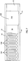
FIG. 7 is a partial top cutaway view of the mover and track segment ofFig. 2 ; -
FIG. 8 is a block diagram representation of the exemplary control system ofFig. 1 ; -
FIG. 9 is a block diagram representation of an exemplary control system for a segment controller in the linear drive system ofFig. 1 ; -
FIG. 10 is a block diagram representation of the exemplary control system ofFig. 9 with an injection sequence illustrated as being added at the current reference; -
FIG. 11 is a block diagram representation of the exemplary control system ofFig. 9 with an injection sequence illustrated as being added at the motion feedback; -
FIG. 12 is a graphical representation of one embodiment of an injection sequence; -
FIG. 13 is a graphical representation of an exemplary position feedback signal illustrating motion of a mover in response to an injection sequence; -
FIG. 14 is a graphical representation of an exemplary frequency response determined for a mover used to characterize operation of the mover; -
FIG. 15 is another graphical representation of an exemplary frequency response determined for a mover used to characterize operation of the mover; and -
FIG. 16 is a comparison of two graphical representations of exemplary frequency responses determined for two separate movers used to characterize operation of each of the movers. - In describing the various embodiments of the invention which are illustrated in the drawings, specific terminology will be resorted to for the sake of clarity.
- The various features and advantageous details of the subject matter disclosed herein are explained more fully with reference to the non-limiting embodiments described in detail in the following description.
- Turning initially to
Figs. 1-4 , an exemplary transport system for moving articles or products includes atrack 10 made up ofmultiple segments 12. According to the illustrated embodiment,multiple segments 12 are joined end-to-end to define the overall track configuration. The illustratedsegments 12 are both straight segments having generally the same length. It is understood that track segments of various sizes, lengths, and shapes may be connected together to form thetrack 10 without deviating from the scope of the invention.Track segments 12 may be joined to form a generally closed loop supporting a set ofmovers 100 movable along thetrack 10. Thetrack 10 is illustrated in a horizontal plane. For convenience, the horizontal orientation of thetrack 10 shown inFig. 1 will be discussed herein. Terms such as upper, lower, inner, and outer will be used with respect to the illustrated track orientation. These terms are relational with respect to the illustrated track and are not intended to be limiting. It is understood that the track may be installed in different orientations, such as sloped or vertical, and include different shaped segments including, but not limited to, straight segments, inward bends, outward bends, up slopes, down slopes and various combinations thereof. The width of thetrack 10 may be greater in either the horizontal or vertical direction according to application requirements. Themovers 100 will travel along the track and take various orientations according to the configuration of thetrack 10 and the relationships discussed herein may vary accordingly. - According to the illustrated embodiment, each
track segment 12 includes anupper portion 17 and alower portion 19. Theupper portion 17 is configured to carry themovers 100 and thelower portion 19 is configured to house the control elements. As illustrated, theupper portion 17 includes a generallyu-shaped channel 15 extending longitudinally along theupper portion 17 of each segment. Thechannel 15 includes abottom surface 16 and a pair ofside walls 13, where eachside wall 13 includes arail 14 extending along an upper edge of theside wall 13. Thebottom surface 16,side walls 13, and rails 14 extend longitudinally along thetrack segment 12 and define a guideway along which themovers 100 travel. According to one embodiment, the surfaces of the channel 15 (i.e., thebottom surface 16,side walls 13 and rails 14) are planar surfaces made of a low friction material along whichmovers 100 may slide. The contacting surfaces of themovers 100 may also be planar and made of a low friction material. It is contemplated that the surface may be, for example, nylon, Teflon®, aluminum, stainless steel and the like. Optionally, the hardness of the surfaces on thetrack segment 12 are greater than the contacting surface of themovers 100 such that the contacting surfaces of themovers 100 wear faster than the surface of thetrack segment 12. It is further contemplated that the contacting surfaces of themovers 100 may be removably mounted to thehousing 11 of themover 100 such that they may be replaced if the wear exceeds a predefined amount. According to still other embodiments, themovers 100 may include low-friction rollers to engage the surfaces of thetrack segment 12. Optionally, the surfaces of thechannel 15 may include different cross-sectional forms with themover 100 including complementary sectional forms. Various other combinations of shapes and construction of thetrack segment 12 andmover 100 may be utilized without deviating from the scope of the invention. - According to the illustrated embodiment, each
mover 100 is configured to slide along thechannel 15 as it is propelled by a linear drive system. Themover 100 includes abody 102 configured to fit within thechannel 15. Thebody 102 includes alower surface 106, configured to engage thebottom surface 16 of the channel, andside surfaces 108 configured to engage theside walls 13 of the channel. Themover 100 further includes ashoulder 105 extending inward from each of the side surfaces 108. Theshoulder 105 has a width equal to or greater than the width of therail 14 protruding into the channel. A neck of the mover then extends upward to atop surface 104 of thebody 102. The neck extends for the thickness of the rails such that thetop surface 104 of thebody 102 is generally parallel with the upper surface of eachrail 14. Themover 100 further includes aplatform 110 secured to thetop surface 104 of thebody 102. According to the illustrated embodiment, theplatform 110 is generally square and the width of theplatform 110 is greater than the width between therails 14. The lower surface of theplatform 110, an outer surface of the neck, and an upper surface of theshoulder 105 define achannel 115 in which therail 14 runs. Thechannel 115 serves as a guide to direct themover 100 along the track. It is contemplated that platforms or attachments of various shapes may be secured to thetop surface 104 of thebody 102. Further, various workpieces, clips, fixtures, and the like may be mounted on the top of eachplatform 110 for engagement with a product to be carried along the track by themover 100. Theplatform 110 and any workpiece, clip, fixture, or other attachment present on the platform may define, at least in part, a load present on themover 100. - The
mover 100 is carried along thetrack 10 by a linear drive system. The linear drive system is incorporated in part on eachmover 100 and in part within eachtrack segment 12. One ormore drive magnets 120 are mounted to eachmover 100. With reference toFig. 3 , thedrive magnets 120 are arranged in a block on the lower surface of each mover. Thedrive magnets 120 includepositive magnet segments 122, having a north pole, N, facing outward from the mover andnegative magnet segments 124, having a south pole, S, facing outward from the mover. According to the illustrated embodiment, twopositive magnet segments 122 are located on the outer sides of the set of magnets and twonegative magnet segments 124 are located between the twopositive magnet segments 122. Optionally, the positive and negative motor segments may be placed in an alternating configuration. In still other embodiments, a singlenegative magnet segment 124 may be located between thepositive magnet segments 122. Various other configurations of thedrive magnets 120 may be utilized without deviating from the scope of the invention. - The linear drive system further includes a series of
coils 150 spaced along the length of thetrack segment 12. With reference also toFig 5 , thecoils 150 may be positioned within ahousing 11 for thetrack segment 12 and below thebottom surface 16 of thechannel 15. Thecoils 150 are energized sequentially according to the configuration of thedrive magnets 120 present on themovers 100. The sequential energization of thecoils 150 generates a moving electromagnetic field that interacts with the magnetic field of thedrive magnets 120 to propel eachmover 100 along thetrack segment 12. - A
segment controller 50 is provided within eachtrack segment 12 to control the linear drive system and to achieve the desired motion of eachmover 100 along thetrack segment 12. Although illustrated inFig. 1 as blocks external to thetrack segments 12, the arrangement is to facilitate illustration of interconnects between controllers. As shown inFig. 2 , it is contemplated that eachsegment controller 50 may be mounted in thelower portion 19 of thetrack segment 12. Eachsegment controller 50 is in communication with acentral controller 170 which is, in turn, in communication with anindustrial controller 180. The industrial controller may be, for example, a programmable logic controller (PLC) configured to control elements of a process line stationed along thetrack 10. The process line may be configured, for example, to fill and label boxes, bottles, or other containers loaded onto or held by themovers 100 as they travel along the line. In other embodiments, robotic assembly stations may perform various assembly and/or machining tasks on workpieces carried along by themovers 100. The exemplaryindustrial controller 180 includes: apower supply 182 with apower cable 184 connected, for example, to a utility power supply; acommunication module 186 connected by anetwork medium 160 to thecentral controller 170; aprocessor module 188; aninput module 190 receivinginput signals 192 from sensors or other devices along the process line; and anoutput module 192 transmittingcontrol signals 193 to controlled devices, actuators, and the like along the process line. Theprocessor module 188 may identify when amover 100 is required at a particular location and may monitor sensors, such as proximity sensors, position switches, or the like to verify that themover 100 is at a desired location. Theprocessor module 188 transmits the desired locations of eachmover 100 to acentral controller 170 where thecentral controller 170 operates to generate commands for eachsegment controller 50. - With reference also to
Fig. 8 , thecentral controller 170 includes aprocessor 174 and amemory device 172. It is contemplated that theprocessor 174 andmemory device 172 may each be a single electronic device or formed from multiple devices. Theprocessor 174 may be a microprocessor. Optionally, theprocessor 174 and/or thememory device 172 may be integrated on a field programmable gate array (FPGA) or an application specific integrated circuit (ASIC). Thememory device 172 may include volatile memory, non-volatile memory, or a combination thereof. Anoptional user interface 176 may be provided for an operator to configure thecentral controller 170 and to load or configure desired motion profiles for themovers 100 on thecentral controller 170. Optionally, the configuration may be performed via a remote device connected via a network and acommunication interface 178 to thecentral controller 170. It is contemplated that thesystem controller 170 anduser interface 176 may be a single device, such as a laptop, notebook, tablet or other mobile computing device. Optionally, theuser interface 176 may include one or more separate devices such as a keyboard, mouse, display, touchscreen, interface port, removable storage medium or medium reader and the like for receiving information from and displaying information to a user. Optionally, thesystem controller 170 and user interface may be an industrial computer mounted within a control cabinet and configured to withstand harsh operating environments. It is contemplated that still other combinations of computing devices and peripherals as would be understood in the art may be utilized or incorporated into thesystem controller 170 anduser interface 176 without deviating from the scope of the invention. - The
central controller 170 includes one or more programs stored in thememory device 172 for execution by theprocessor 174. Thesystem controller 170 receives a desired position from theindustrial controller 180 and determines one or more motion profiles for themovers 100 to follow along thetrack 10. A program executing on theprocessor 174 is in communication with eachsegment controller 50 on each track segment via anetwork medium 160. Thesystem controller 170 may transfer a desired motion profile to eachsegment controller 50. Optionally, thesystem controller 170 may be configured to transfer the information from theindustrial controller 180 identifying one or more desiredmovers 100 to be positioned at or moved along thetrack segment 12, and thesegment controller 50 may determine the appropriate motion profile for eachmover 100. - A position feedback system provides knowledge of the location of each
mover 100 along the length of thetrack segment 12 to thesegment controller 50. According to one embodiment of the invention, illustrated inFigs. 2 and 4 , the position feedback system includes one ormore position magnets 140 mounted to themover 100 and an array ofsensors 145 spaced along theside wall 13 of thetrack segment 12. Thesensors 145 are positioned such that each of theposition magnets 140 are proximate to the sensor as themover 100 passes eachsensor 145. Thesensors 145 are a suitable magnetic field detector including, for example, a Hall Effect sensor, a magneto-diode, an anisotropic magnetoresistive (AMR) device, a giant magnetoresistive (GMR) device, a tunnel magnetoresistance (TMR) device, fluxgate sensor, or other microelectromechanical (MEMS) device configured to generate an electrical signal corresponding to the presence of a magnetic field. Themagnetic field sensor 145 outputs a feedback signal provided to thesegment controller 50 for thecorresponding track segment 12 on which thesensor 145 is mounted. The feedback signal may be an analog signal provided to afeedback circuit 58 which, in turn, provides a signal to theprocessor 52 corresponding to themagnet 140 passing thesensor 145. - According to another embodiment of the invention, illustrated in
Figs. 5 and 6 , the position feedback system utilizes thedrive magnets 120 as position magnets.Position sensors 145 are positioned along thetrack segment 12 at a location suitable to detect the magnetic field generated by thedrive magnets 120. According to the illustrated embodiment, theposition sensors 145 are located below thecoils 150. Optionally, theposition sensors 145 may be interspersed with thecoils 150 and located, for example, in the center of a coil or between adjacent coils. According to still another embodiment, theposition sensors 145 may be positioned within theupper portion 17 of thetrack segment 12 and near thebottom surface 16 of thechannel 15 to be aligned with thedrive magnets 120 as eachmover 100 travels along thetracks segment 12. - The
segment controller 50 also includes acommunication interface 56 that receives communications from thecentral controller 170 and/or fromadjacent segment controllers 50. Thecommunication interface 56 extracts data from the message packets on the industrial network and passes the data to aprocessor 52 executing in thesegment controller 50. The processor may be a microprocessor. Optionally, theprocessor 52 and/or amemory device 54 within thesegment controller 50 may be integrated on a field programmable gate array (FPGA) or an application specific integrated circuit (ASIC). It is contemplated that theprocessor 52 andmemory device 54 may each be a single electronic device or formed from multiple devices. Thememory device 54 may include volatile memory, non-volatile memory, or a combination thereof. Thesegment controller 50 receives the motion profile or desired motion of themovers 100 and utilizes the motion commands to controlmovers 100 along thetrack segment 12 controlled by thatsystem controller 30. - Each
segment controller 50 generates switching signals to generate a desired current and/or voltage at eachcoil 150 in thetrack segment 12 to achieve the desired motion of themovers 100. The switching signals 72 control operation of switching devices 74 for thesegment controller 50. According to the illustrated embodiment, thesegment controller 50 includes a dedicatedgate driver module 70 which receives command signals from theprocessor 52, such as a desired voltage and/or current to be generated in eachcoil 150, and generates the switching signals 72. Optionally, theprocessor 52 may incorporate the functions of thegate driver module 70 and directly generate the switching signals 72. The switching devices 74 may be a solid-state device that is activated by the switching signal, including, but not limited to, transistors, thyristors, or silicon-controlled rectifiers. - According to the illustrated embodiment, the track receives power from a distributed DC voltage. A
DC bus 20 receives a DC voltage, VDC, from a DC supply and conducts the DC voltage to eachtrack segment 12. The illustratedDC bus 20 includes twovoltage rails track segment 12, it is contemplated that theDC bus 20 would extend within thelower portion 19 of the track segment. Eachtrack segment 12 includes connectors to which either the DC supply or another track segment may be connected such that theDC bus 20 may extend for the length of thetrack 10. Optionally, eachtrack segment 12 may be configured to include a rectifier section (not shown) and receive an AC voltage input. The rectifier section in eachtrack segment 12 may convert the AC voltage to a DC voltage utilized by the corresponding track segment. - The DC voltage from the
DC bus 20 is provided at theinput terminals first input terminal 21 and a second voltage potential is present at thesecond input terminal 23. The DC bus extends into the power section defining apositive rail 22 and anegative rail 24 within the segment controller. The terms positive and negative are used for reference herein and are not meant to be limiting. It is contemplated that the polarity of the DC voltage present between theinput terminals negative rail 24 is greater than the potential on thepositive rail 22. Each of the voltage rails 22, 24 are configured to conduct a DC voltage having a desired potential, according to application requirements. According to one embodiment of the invention, thepositive rail 22 may have a DC voltage at a positive potential and thenegative rail 24 may have a DC voltage at ground potential. Optionally, thepositive rail 22 may have a DC voltage at ground potential and thenegative rail 24 may have a DC voltage at a negative potential According to still another embodiment of the invention, thepositive rail 22 may have a first DC voltage at a positive potential with respect to the ground potential and thenegative rail 24 may have a second DC voltage at a negative potential with respect to the ground potential. The resulting DC voltage potential between the tworails positive rail 22 and thenegative rail 24. - It is further contemplated that the DC supply may include a
third voltage rail 26 having a third voltage potential. According to one embodiment of the invention, thepositive rail 22 has a positive voltage potential with respect to ground, thenegative rail 24 has a negative voltage potential with respect to ground, and thethird voltage rail 26 is maintained at a ground potential. Optionally, thenegative voltage rail 24 may be at a ground potential, thepositive voltage rail 22 may be at a first positive voltage potential with respect to ground, and thethird voltage rail 26 may be at a second positive voltage potential with respect to ground, where the second positive voltage potential is approximately one half the magnitude of the first positive voltage potential. With such a split voltage DC bus, two of the switching devices 74 may be used in pairs to control operation of onecoil 150 by alternately provide positive or negative voltages to one thecoils 150. - The power section in each
segment controller 50 may include multiple legs, where each leg is connected in parallel between thepositive rail 22 and thenegative rail 24. According to the illustrated embodiment, three legs are shown. However, the number of legs may vary and will correspond to the number ofcoils 150 extending along thetrack segment 12. Each leg includes afirst switching device 74a and asecond switching device 74b connected in series between thepositive rail 22 and thenegative rail 24 with acommon connection 75 between the first andsecond switching devices first switching device 74a in each leg 221 may also be referred to herein as an upper switch, and thesecond switching device 74b in each leg 221 may also be referred to herein as a lower switch. The terms upper and lower are relational only with respect to the schematic representation and are not intended to denote any particular physical relationship between the first andsecond switching devices common connection 75 and either the positive ornegative rail - The
processor 52 also receives feedback signals from sensors providing an indication of the operating conditions within the power segment or of the operating conditions of acoil 150 connected to the power segment. According to the illustrated embodiment, the power segment includes avoltage sensor 62 and acurrent sensor 60 at the input of the power segment. Thevoltage sensor 62 generates a voltage feedback signal and thecurrent sensor 60 generates a current feedback signal, where each feedback signal corresponds to the operating conditions on thepositive rail 22. Thesegment controller 50 also receives feedback signals corresponding to the operation ofcoils 150 connected to the power segment. Avoltage sensor 153 and acurrent sensor 151 are connected in series with thecoils 150 at each output of the power section. Thevoltage sensor 153 generates a voltage feedback signal and thecurrent sensor 151 generates a current feedback signal, where each feedback signal corresponds to the operating condition of thecorresponding coil 150. Theprocessor 52 executes a program stored on thememory device 54 to regulate the current and/or voltage supplied to each coil and theprocessor 52 and/orgate driver module 70 generates switching signals 72 which selectively enable/disable each of the switching devices 74 to achieve the desired current and/or voltage in eachcoil 150. The energized coils 150 create an electromagnetic field that interacts with thedrive magnets 120 on eachmover 100 to control motion of themovers 100 along thetrack segment 12. - In operation, the load may vary on a
mover 100 as the mover travels along the track. As previously discussed, themover 100 includes aplatform 110 secured to thetop surface 104 of thebody 102 of themover 100. It is contemplated that platforms or attachments of various shapes may be secured to thetop surface 104 of thebody 102. Further, various workpieces, clips, fixtures, and the like may be mounted on the top of eachplatform 110 for engagement with a product to be carried along the track by themover 100. Theplatform 110 and any workpiece, clip, fixture, or other attachment present on the platform may define, at least in part, a load present on themover 100. For a given system, eachmover 100 may have the same platform and/or attachments to uniformly interact with identical product being loaded on and off themover 100. The product may constitute an additional load and may vary at different locations along a track. For example, amover 100 may initially have no additional load present. At a first station, a container, such as a box, bottle, or the like may be loaded on to themover 100. At a second station, product may be partially or fully loaded into the container. At additional stations, steps, such as additional loading, closing, labeling, and the like may be taken that further alter the load present on each mover. At a final station, the load may be removed and themover 100 returns to the initial station. According to the exemplary application, the load varies along each section of track after additional packaging and/or product is placed on themover 100. In addition, wear or damage on contacting surfaces, bearings, and the like may cause variations in the loading betweenmovers 100 or variations in loading for a single mover over time. - In order to optimize performance of the linear drive system, it is desirable to characterize loads present on the
movers 100 at various locations along the track. According to one embodiment of the present invention, thesegment controller 50 may be configured to provide a characterization of a load present on eachmover 100 as it travels along thecorresponding track segment 12. Themover 100 is initially positioned at a point of interest along atrack segment 12. The expected load to be present on themover 100 may also be included on the mover. For example, if a container and/or product is present on themover 100 during operation, an appropriate container and/or product may be loaded on themover 100 prior to characterization. As will be discussed in more detail below, thesegment controller 50 then executes a characterization module to obtain a frequency response corresponding to performance of amover 100 at a location and with an expected load. Optionally, thesegment controller 50 may sample data and transmit stored data to thecentral controller 170 or to another remote processing device to obtain the frequency response corresponding to performance of themover 100 at a location and with an expected load. - With reference next to
Fig. 9 , a block diagram of anexemplary control module 200 executing on theprocessor 52 of asegment controller 50 is illustrated. Theexemplary control module 200 receives amotion reference 202. The motion reference may be a position command or a velocity command corresponding to a desired location or speed of themover 100. Amotion regulator 204 executes on thesegment controller 50 to control eachmover 100 to the desired position or at the desired speed according to themotion reference 202. Themotion regulator 204 includes a controller with a Proportional (P) control path, an Integral (I) control path, a Derivative (D) control path, or any combination thereof. In addition, themotion regulator 204 may further include additional feedforward, or feedback paths according to the control requirements. A motion feedback signal 214 corresponding to the actual position or velocity of themover 100 is provided to themotion regulator 204. Themotion regulator 204 compares themotion feedback signal 214 to themotion reference signal 202 and executes the control path(s) present in the regulator to generate acurrent reference signal 206. - The
current reference signal 206 is provides as an input to acurrent regulator 208. Thecurrent regulator 206 executes on thesegment controller 50 to control the amount of current output to eachcoil 150, which in turn, interacts with thedrive magnets 120 on eachmover 100 to locate eachmover 100 at the desired position or propel themover 100 at the desired speed according to themotion reference 202. Thecurrent regulator 206 includes a controller with a Proportional (P) control path, an Integral (I) control path, a Derivative (D) control path, or any combination thereof. In addition, thecurrent regulator 206 may further include additional feedforward, or feedback paths according to the control requirements. A current feedback signal is generated by eachcurrent sensor 153 corresponding to the actual output current 210 supplied to acoil 150. Thecurrent regulator 206 compares the current feedback signal to thecurrent reference signal 206 and executes the control path(s) present in the regulator and, in tandem with thegate driver 70, generates the switching signals 72 to produce the output current 210 for eachcoil 150. - The
linear motor 211 includes both the drive coils 150 extending along eachtrack segment 12 and thedrive magnets 120 present on eachmover 100. Thecurrent output 210 from thesegment controller 50 generates an electromagnetic field from eachcoil 150 that interacts with the magnetic field generated by thedrive magnets 120 such that themovers 100 follow themotion reference signal 202. - According to the illustrated embodiment, the
control module 200 also includes anobserver 212 that generates an estimatedmotion feedback signal 214. The estimated motion feedback signal may be an estimated position signal or an estimated velocity signal such that themotion feedback signal 214 corresponds to themotion reference signal 202. Theobserver 212 may receive, for example, any of the signals in the control module including themotion reference 202, thecurrent reference 206, thecurrent output 210, an output voltage, or a combination thereof. Anobserver 212 generates an estimated feedback signal as a function of the reference signals and of the expected dynamics of themover 100. - According to still another embodiment, the
motion feedback signal 214 may be generated as a function of a measured feedback signal. The motion feedback signal may correspond, for example, to a signal from aposition sensor 145 detecting either aposition magnet 140 or adrive magnet 120 passing theposition sensor 145. In still other embodiments, themotion feedback signal 214 may be determined as a function of both measured and commanded signals. - Turning next to
Figs. 10 and 11 , thesegment controller 50 may be configured to insert aninjection sequence 218 into thecontrol module 200. According to the embodiment illustrated inFig. 10 , aninjection sequence 218 is added at a summingjunction 216 to thecurrent reference signal 206 before providing the resulting signal to thecurrent regulator 208. According to the embodiment illustrated inFig. 11 , aninjection sequence 218 is added at a summingjunction 220 to themotion feedback signal 214 before providing the resulting signal to themotion regulator 204. In either instance, the injection sequence is a pseudorandom binary sequence (PRBS). The sequence is selected such that it exhibits the behavior of a random sequence; however, the sequence is generated in a deterministic manner to ensure that the content of the sequence has harmonic content across a desired range of frequencies for evaluation. - With reference also to
Fig. 12 , anexemplary segment 218 of a PRBS is illustrated. The PRBS includes a sequence of bits which are either a logical zero 225 or alogical one 230. As seen inFig. 12 , theexemplary segment 218 of the PRBS transitions between either a logical zero 225 or alogical one 230 at varying time intervals. The PRBS has a fixed length, but exhibits randomness in the sense that there is no correlation between any one value of the sequence and another value of the sequence. The PRBS may be generated by theprocessor 52 executing a pseudorandom sequence generator routine from which the series ofzeros 225 andones 230 are output. The PRBS may be stored in thememory device 54 for subsequent usage or, alternately, a new PRBS may be generated each time a characterization process is executed. - In order to characterize a particular load on a
mover 100, themover 100 is first positioned at a desired location with a desired load applied. A zero motion reference signal is then applied to thecontrol module 200 such that the control module attempts to hold themover 100 at the selected location. Addition of theinjection sequence 218 either to thecurrent reference 206 or to themotion feedback signal 214 appears as a disturbance to thecontrol module 200. In other words, thecontrol module 200 interprets the injection signal as either motion on themover 100 or an extra current required to hold themover 100 at its present location. Themotion regulator 204 and/or thecurrent regulator 208 attempt to compensate for theinjection sequence 218. As a result of the compensation, a small amount of movement occurs on themover 100. With reference, for example, toFig. 13 , aplot 240 of a mover position signal 245 corresponding to the actual position of amover 100 with respect to the original position (i.e., zero (0) mm) during application of the injection sequence is illustrated. - While the
injection sequence 218 is being added to thecontrol module 200, thesegment controller 50 stores samples of theinjection sequence 218 and the position signal 245 resulting from the addition of the injection sequence inmemory 54. Theinjection sequence 218 serves as an input signal to thecontrol module 200 and the position signal 245 is a response signal from thecontrol module 200. It is contemplated that various other signals with thecontrol module 200 may be sampled, such as thecurrent reference 206 orcurrent output 210 to obtain a response signal of thecontrol module 200 resulting from the addition of theinjection sequence 218. Theinjection sequence 218 is applied for a predefined duration and a number of samples for both the input signal and the response signal are stored in order to obtain a frequency response of thecontrol module 200 across a desired range of frequencies. - After sampling the input and response signals, a frequency response of the stored data is obtained. The frequency response is an analysis of a signal which determines a magnitude and phase of the signal as a function of frequency. In order to determine the frequency response of a signal, a continuous function defining the signal may be determined and a Fourier transform of the continuous function is performed. The Fourier transform expresses the function as a function of frequencies over an infinite frequency interval. However, determining the Fourier transform of a continuous function is computationally intensive. In order to reduce the computation requirements for the frequency analysis of the signal to a suitable level for real-time control, the signal is sampled over a defined sample interval at a sampling frequency and the sampled data is stored in memory. This sampled data may be, for example, the injection sequence and the sampled position feedback signal.
- Traditionally, a Discrete Fourier Transform (DFT) is performed on the sampled data to express the stored signal as a discrete set of complex vectors having magnitude and phase information of the signal over a finite frequency interval. A common DFT algorithm is given in
Equation 1 below. However, it is contemplated that other DFT algorithms or Fast Fourier Transform (FFT) algorithms may be utilized without deviating from the scope of the invention.
- X(k) = vector having a magnitude and phase information for "K" evenly spaced frequency bins
- N = maximum number of samples
- n = sample number
- x(n) = array of sampled data
- k = an integral index value selected from the range of 1 to K
- K = number of evenly spaced frequency bins between zero hertz and the sampling frequency and typically equal to one half of the maximum number of samples
- Having obtained the magnitude and phase information of the sampled data, a Bode plot may be generated to characterize the frequency response of a
mover 100 resulting from addition of theinjection sequence 218. The Bode plot provides magnitude and phase information of a transfer function describing the system as a function of the input and output signals. The magnitude of the transfer function may be determined by dividing the magnitude of the frequency response for the output signal by the magnitude of the frequency response for the input signal at each frequency. The phase of the transfer function may be determined by subtracting the phase of the input signal from the phase of the output signal at each frequency. Exemplary plots of the magnitude components of a Bode plot are shown inFigs. 14-16 . - Analysis of the frequency response may be performed to identify the frequency component or components having the greatest magnitude information, or the maximum value. In an unstable system, this maximum value typically corresponds to a resonant, or anti-resonant, frequency. With reference, for example, to
Fig. 14 , theBode plot 300 includes amagnitude plot 302 for a single mover that exhibits a smallresonant peak 304 at about 1.5 Hz. In some embodiments, the frequency response may be transmitted from the segment controller to the central controller or to a remote processing unit. Optionally, the frequency response may be determined directly on the central controller or the remote processing unit. At the central controller or remote processing unit, the frequency response may be displayed on a visual display to provide a graphical representation of the frequency response to an operator. - Analysis of the frequency response may further be performed to compare the frequency response for one mover to the frequency response for another mover. Optionally, a nominal
frequency response plot 325, such as that illustrated in theBode plot 320 ofFig. 15 may be stored inmemory 54 of thesegment controller 50. The nominalfrequency response plot 325 may be obtained, for example, by a commissioning routine in which a knownmover 100 is positioned at a predefined location that exhibits a desired operating characteristic. In general, as the value of the magnitude increases at a particular frequency, the harmonic content present in the response signal for that frequency is increasing as well. Thus, a lower magnitude indicates less harmonic content present in the response signal. The desired operating characteristic may be, therefore, a frequency response with a set of maximum values for the magnitude of frequency content present at the different frequencies. According to another aspect of the invention, the desired operating characteristic may be a mover operating under a known condition, such that subsequent comparisons to other movers or at other locations along the track may be made to a known operating condition. - Turning next to
Fig. 16 , a comparison of thefrequency responses movers 100 or for one mover at two different locations may be used to identify an undesirable operating condition. The nominalfrequency response plot 325 fromFig. 15 is included in theBode plot 340 illustrated inFig. 16 . A secondfrequency response plot 330 is illustrated as well. As may be observed from theplot 340 inFig. 16 , the secondfrequency response plot 330 has a generally lower magnitude than the nominalfrequency response plot 325. The lower magnitude may be due, for example, to increased loading of themover 100 or an increased friction between themover 100 and the track at a second location. The increased weight or increase friction may, generally result in more damping of harmonic components in themover 100. However, the secondfrequency response plot 330 also exhibits aresonant operating point 332 at about 20 Hertz. Theresonant operating point 332 may be caused by an instability introduced by the load or by the increased friction at the second location. - Having identified the
resonant operating point 332, thesegment controller 50 may be configured to compensate for theresonant operating point 332. According to one embodiment of the invention, thesegment controller 50 may, for example, be configured to execute with a different set of controller gains to reduce the effects of theresonant operating point 332. During a commissioning run, a central controller may command amover 100 to travel the entire length of thetrack 10. Along eachtrack segment 12, eachsegment controller 50 may be configured to execute the characterization module to obtain one or more frequency responses of themover 100 along thetrack segment 12. Further, it is contemplated that the characterization module may utilize multiple sets of controller gains with amover 100 and a given load to obtain different frequency responses for each set of controller gains. Thesegment controller 50 identifies one of the frequency responses as providing the best response according, for example, to a comparison of gain margin and/or phase margin of each response or to the bandwidth of each response. The different sets of controller gains may be stored inmemory 54 of the segment controller. - During operation, the
segment controller 50 may be configured to select a set of controller gains according to the best response identified during the commissioning run. In addition, ifdifferent movers 100 ormovers 100 having different loads are to travel along a track segment, multiple commissioning runs may be executed with each mover and/or the varying loads. A table may be established that identifies different movers and/or different loads present on the mover and the corresponding set of controller gains that provide the preferred frequency response. As amover 100 reaches a track segment, the segment controller may utilize the corresponding set of controller gains for each mover and/or load present on the mover according to the table established during the commissioning run. It is further contemplated that the table may identify more than one set of controller gains for amover 100 along a single track segment if, for example, the load changes as themover 100 travels along thetrack segment 12. Thesegment controller 50 may be further configured to select a first set of controller gains along a first portion of the track segment and a second set of controller gains along a second portion of the track segment. - It is further known that contacting surfaces between the
mover 100 and thetrack segment 12 may wear over time. During an initial commissioning run, atrack segment 12 may execute the characterization module to obtain one or more initial frequency responses of themover 100 along thetrack segment 12. Each of the initial frequency responses obtained may be stored inmemory 54 of thesegment controller 50. At periodic intervals, the system may be commanded to execute subsequent characterization of the track segment. The interval may be set according to a maintenance schedule based, for example, on time or operation or on number of movers traveling across each location to obtain new frequency responses. The new frequency responses may be compared to the initial frequency responses to identify changes in operating conditions for a mover and/or a track segment. If a difference between a new frequency response and an initial frequency response exceeds a predefined threshold, a warning message may be posted alerting an operator to required maintenance.
Claims (14)
- A system, comprising:a plurality of movers (100), wherein each of the plurality of movers includes:a load mounted to the mover, andat least one drive magnet (120) mounted to the mover;a track (10) including a plurality of track segments (12) defining a closed path along which each of the plurality of movers (100) travels, wherein each of the plurality of track segments (12) includes a plurality of drive coils (150) spaced along the track segment (12) and a memory device (54);a processor configured to: execute a control module (200) which generates an output current (210) for each of the plurality of drive coils (150) to obtain a desired motion of each of the plurality of movers (100) along the track segment (12),characterized in thatthe processor is further configured to:generate an injection sequence (218) having a plurality of harmonic components, add the injection sequence into the control module (200) while commanding each of the plurality of movers (100) to remain at a present location along the track segment (12),store a plurality of samples of at least one position feedback signal in the memory device (54), wherein each position feedback signal corresponds to motion of one of the plurality of movers (100) positioned along the track segment (12) while the injection sequence (218) is added into the control module (200); andgenerate a frequency response of each mover (100) positioned along the track segment (12) as a function of the injection sequence (218) and of the sampled position feedback signal; andthe system further comprisesa visual display unit, wherein the frequency response is graphically represented on the visual display unit.
- The system of claim 1 wherein the load is fixedly mounted to the mover (100) and the frequency response corresponds to operation of the mover (100).
- The system of claim 1 wherein:the load is removably mounted to the mover (100),the processor is further operative to generate a first frequency response and a second frequency response,the first frequency response is generated with the load mounted to the mover (100), andthe second frequency response is generated with the load removed from the mover (100).
- The system of claim 3 wherein the processor is further configured to identify a resonant operating point (304; 332) in one of the first frequency response and the second frequency response; or
wherein the memory device is further configured to store a set of maximum values for each frequency present in the first and the second frequency responses and wherein the processor is further operative to determine when a magnitude at one of the frequencies present in each of the first and the second frequency responses is greater than the corresponding maximum value. - The system of any one of claims 1 to 4, wherein at least one of the plurality of movers (100) is moved to a plurality of locations along one of the track segments (12) and the frequency response is generated for the mover (100) at each of the plurality of locations.
- The system of claim 5, wherein the processor is further operative to evaluate the frequency response at each of the plurality of locations to identify a resonant operating point (304; 332) in at least one of the frequency responses; or
wherein a nominal frequency response (325) for the mover (100) is stored in the memory device and wherein the processor is further operative to:compare the frequency response obtained at each of the plurality of locations to the nominal frequency response, andidentify at least one location as having a fault when a difference between the frequency response obtained at each of the plurality of locations exceeds a predetermined threshold from the nominal frequency response. - The system of any one of claims 1 to 6, wherein the injection sequence (218) is a pseudo random binary sequence; or
further comprising a segment controller (50) in each of the plurality of track segments (12) wherein the processor is included in each segment controller (50). - The system of any one of claims 1 to 7 further comprising:a segment controller (50) having a local processor (52); anda central controller (170) having a remote processor (174), wherein at least a first portion of the steps the processor is operative to perform are performed on the local processor and at least a second portion of the steps the processor is operative to perform are performed on the remote processor.
- A method, comprising the steps of:executing a control module (200) in a segment controller (50) to generate an output current for each coil (150) spaced along a track segment (12) included in a track (10), wherein the track (10) includes a plurality of track segments (12) defining a closed path along which each of a plurality of movers (100) travels;characterized bygenerating an injection sequence (218) with the segment controller (50), wherein the injection sequence (218) includes a plurality of harmonic components;inserting the injection sequence (218) into the control module (200) while commanding each of the plurality of movers (100) to remain at a present location along the track segment (12);storing a plurality of samples of at least one position feedback signal in a memory device (54) in the segment controller (50), wherein each position feedback signal corresponds to motion of one of the plurality of movers (100) positioned along the track segment (12) while the injection sequence (218) is added into the control loop;generating a frequency response of each mover (100) positioned along the track segment (12) as a function of the injection sequence (218) and of the sampled position feedback signal; andgraphically representing the frequency response on a visual display unit.
- The method of claim 9 wherein the injection sequence (218) is a pseudo random binary sequence; or
further comprising the steps of:moving at least one of the plurality of movers (100) to a plurality of locations along one of the track segments (12), andgenerating the frequency response for the mover (100) at each of the plurality of locations. - The method of claim 10, further comprising the step of evaluating the frequency response at each of the plurality of locations to identify a resonant operating point (304; 332) in at least one of the frequency responses; or
wherein a nominal frequency response (325) for the mover (100) is stored in the memory device, the method further comprising the steps of:comparing the frequency response obtained at each of the plurality of locations to the nominal frequency response, andidentifying at least one location as having a fault when a difference between the frequency response obtained at each of the plurality of locations exceeds a predetermined threshold from the nominal frequency response. - The method of any one of claims 9 to 11, wherein the load is fixedly mounted to the mover (100) and the frequency response corresponds to operation of the mover (100).
- The method of any one of claims 9 to 11, wherein the load is removably mounted to the mover (100), the method further comprising the steps of:generating a first frequency response with the load mounted to the mover (100), andgenerating a second frequency response with the load removed from the mover (100).
- The method of claim 13 further comprising the step of identifying a resonant operating point (304; 332) in one of the first frequency response and the second frequency response.
Applications Claiming Priority (1)
| Application Number | Priority Date | Filing Date | Title |
|---|---|---|---|
| US15/702,983 US11165372B2 (en) | 2017-09-13 | 2017-09-13 | Method and apparatus to characterize loads in a linear synchronous motor system |
Publications (2)
| Publication Number | Publication Date |
|---|---|
| EP3457559A1 EP3457559A1 (en) | 2019-03-20 |
| EP3457559B1 true EP3457559B1 (en) | 2021-07-14 |
Family
ID=63528540
Family Applications (1)
| Application Number | Title | Priority Date | Filing Date |
|---|---|---|---|
| EP18193080.1A Active EP3457559B1 (en) | 2017-09-13 | 2018-09-07 | Method and system to characterize loads in a linear synchronous motor system |
Country Status (2)
| Country | Link |
|---|---|
| US (1) | US11165372B2 (en) |
| EP (1) | EP3457559B1 (en) |
Families Citing this family (23)
| Publication number | Priority date | Publication date | Assignee | Title |
|---|---|---|---|---|
| US10528700B2 (en) | 2017-04-17 | 2020-01-07 | Rockwell Automation Technologies, Inc. | Industrial automation information contextualization method and system |
| US10620612B2 (en) | 2017-06-08 | 2020-04-14 | Rockwell Automation Technologies, Inc. | Predictive maintenance and process supervision using a scalable industrial analytics platform |
| US10562715B2 (en) * | 2017-09-12 | 2020-02-18 | Magnemotion, Inc. | Method and apparatus to diagnose a linear synchronous motor system |
| US10367404B2 (en) * | 2017-09-29 | 2019-07-30 | Rockwell Automation Technologies, Inc. | Mid-bus voltage generation via idle phases in a linear motor track system |
| US11144042B2 (en) | 2018-07-09 | 2021-10-12 | Rockwell Automation Technologies, Inc. | Industrial automation information contextualization method and system |
| KR102164594B1 (en) * | 2018-11-15 | 2020-10-12 | 한국기계연구원 | Linear motor and controlling system of the same |
| US11027615B2 (en) * | 2018-11-29 | 2021-06-08 | Rockwell Automation Technologies, Inc. | System and method for improving travel across joints in a track for a linear motion system |
| US11403541B2 (en) | 2019-02-14 | 2022-08-02 | Rockwell Automation Technologies, Inc. | AI extensions and intelligent model validation for an industrial digital twin |
| US11086298B2 (en) | 2019-04-15 | 2021-08-10 | Rockwell Automation Technologies, Inc. | Smart gateway platform for industrial internet of things |
| JP7083964B2 (en) * | 2019-04-23 | 2022-06-13 | ヤマハ発動機株式会社 | Linear conveyor system, control method of linear conveyor system, control program of linear conveyor system and recording medium |
| US11435726B2 (en) | 2019-09-30 | 2022-09-06 | Rockwell Automation Technologies, Inc. | Contextualization of industrial data at the device level |
| US11841699B2 (en) | 2019-09-30 | 2023-12-12 | Rockwell Automation Technologies, Inc. | Artificial intelligence channel for industrial automation |
| US11249462B2 (en) | 2020-01-06 | 2022-02-15 | Rockwell Automation Technologies, Inc. | Industrial data services platform |
| US11599101B2 (en) * | 2020-02-26 | 2023-03-07 | Rockwell Automation Technologies, Inc. | Independent mover transport system and method of extending range of operations in an independent mover transport system |
| US11726459B2 (en) | 2020-06-18 | 2023-08-15 | Rockwell Automation Technologies, Inc. | Industrial automation control program generation from computer-aided design |
| US11718482B2 (en) * | 2020-08-31 | 2023-08-08 | Rockwell Automation Technologies, Inc. | System and method of monitoring disturbance force in an independent cart system, compensation of said disturbance force |
| US11964685B2 (en) * | 2022-02-07 | 2024-04-23 | Rockwell Automation Technologies, Inc. | System and method for control of carts at a station for an independent cart system |
| US12540038B2 (en) * | 2022-05-31 | 2026-02-03 | Rockwell Automation Technologies, Inc. | Automatic tuning and control of a linear drive based independent cart system with initial value compensation |
| DE112022007181T5 (en) * | 2022-11-11 | 2025-04-24 | Mitsubishi Electric Corporation | conveyor system |
| US20240375518A1 (en) | 2023-05-09 | 2024-11-14 | Rockwell Automation Technologies, Inc. | Systems and methods for synchronous motor system diagnostics |
| EP4498594A1 (en) * | 2023-07-26 | 2025-01-29 | Schneider Electric Industries Sas | Method for synchronously controlling two motors |
| US20250145374A1 (en) * | 2023-11-05 | 2025-05-08 | Rockwell Automation Technologies, Inc. | System and Method to Monitor and Balance Wear in an Independent Cart System |
| WO2025184219A1 (en) * | 2024-02-27 | 2025-09-04 | Siemens Healthcare Diagnostics Inc. | Multi-pole magnet vessel mover navigation |
Family Cites Families (71)
| Publication number | Priority date | Publication date | Assignee | Title |
|---|---|---|---|---|
| US3641939A (en) * | 1968-10-17 | 1972-02-15 | Merlin Gerin | Speed control system for linear motor conveyors |
| US3850109A (en) * | 1973-04-30 | 1974-11-26 | Massachusetts Inst Technology | Transportation system employing magnetic levitation, guidance and propulsion |
| US4718539A (en) * | 1985-01-02 | 1988-01-12 | Hitachi, Ltd. | Conveyor means |
| US4853602A (en) * | 1985-12-24 | 1989-08-01 | E. I. Dupont De Nemours And Company | System for using synchronous secondaries of a linear motor to biaxially draw plastic films |
| GB2185720B (en) * | 1986-01-27 | 1989-11-01 | Daifuku Kk | Conveyor system utilizing linear motor |
| US4704568A (en) * | 1986-04-14 | 1987-11-03 | Unico, Inc. | Linear induction motor transport system |
| DE3906422C1 (en) * | 1989-03-01 | 1990-10-18 | Lindemann Maschinenfabrik Gmbh, 4000 Duesseldorf, De | |
| EP0346815A3 (en) * | 1988-06-13 | 1990-12-19 | Asahi Glass Company Ltd. | Vacuum processing apparatus and transportation system thereof |
| US4988273A (en) * | 1989-06-23 | 1991-01-29 | Cincinnati Milacron Inc. | Injection molding machines having a brushless DC drive system |
| DE4315307A1 (en) * | 1993-05-07 | 1994-11-10 | Krupp Maschinentechnik | Device for taking over and forwarding container lids made of ferromagnetic material |
| US5585709A (en) * | 1993-12-22 | 1996-12-17 | Wisconsin Alumni Research Foundation | Method and apparatus for transducerless position and velocity estimation in drives for AC machines |
| ATE174306T1 (en) * | 1994-09-06 | 1998-12-15 | Mannesmann Ag | SORTING SYSTEM WITH CROSS BELT |
| DE19524485A1 (en) * | 1995-07-05 | 1997-01-09 | Kumeth Siegmund | Conveyor system for small electrical components or modules - has workpieces in mountings which form rotor elements for linear reluctance motors whose stators are on conveyor belt |
| US6148784A (en) * | 1995-08-31 | 2000-11-21 | Isad Electronic Systems Gmbh & Co. Kg | Drive systems, especially for a motor vehicle, and method of operating same |
| US5821713A (en) * | 1995-09-11 | 1998-10-13 | Advanced Motion Controls, Inc. | Commutation position detection system and method |
| NL1003035C2 (en) * | 1996-05-06 | 1997-11-07 | Ebm Techniek Bv | Carrier device for carrying a number of products, as well as system provided with such a carrier device. |
| US5904101A (en) * | 1997-04-22 | 1999-05-18 | Power Superconductor Applications Co., Inc. | Auxiliary propulsion for magnetically levitated vehicle |
| US6621183B1 (en) * | 1997-12-05 | 2003-09-16 | Auckland Uniservices, Ltd. | Supply of power to primary conductors |
| US6101952A (en) * | 1997-12-24 | 2000-08-15 | Magnemotion, Inc. | Vehicle guidance and switching via magnetic forces |
| US7170241B1 (en) * | 1998-02-26 | 2007-01-30 | Anorad Corporation | Path module for a linear motor, modular linear motor system and method to control same |
| US6279728B1 (en) * | 1998-07-20 | 2001-08-28 | Norbert G Jung | Electro-magnetic conveyor |
| DE10005611A1 (en) * | 2000-02-09 | 2001-08-30 | Randolf Hoche | Method and device for moving an element |
| EP1164358B1 (en) * | 2000-06-16 | 2005-08-24 | AMO Automatisierung Messtechnik Optik GmbH | Inductive length measuring system |
| US20020022903A1 (en) * | 2000-08-14 | 2002-02-21 | Krah Jens Onno | Frequency domain auto-tune for an internal motor controller |
| US8217605B2 (en) * | 2000-11-10 | 2012-07-10 | Freescale Semiconductor, Inc. | Motor controller for determining a position of a rotor of an AC motor, AC motor system, and method of determining a position of a rotor of an AC motor |
| AU783789B2 (en) * | 2001-02-07 | 2005-12-08 | Denipro Ag | Conveyor system |
| US6983701B2 (en) | 2001-10-01 | 2006-01-10 | Magnemotion, Inc. | Suspending, guiding and propelling vehicles using magnetic forces |
| US6895352B2 (en) * | 2002-03-12 | 2005-05-17 | Itt Manufacturing Enterprises, Inc. | Simultaneous rapid open and closed loop bode plot measurement using a binary pseudo-random sequence |
| US6703805B2 (en) * | 2002-04-12 | 2004-03-09 | Mountain Engineering Ii, Inc. | System for measuring the position of an electric motor |
| EP1547230B1 (en) * | 2002-06-05 | 2017-03-22 | Jacobs Automation, Inc. | Controlled motion system |
| DE10240080A1 (en) * | 2002-08-30 | 2004-03-11 | Siemens Ag | Method for wireless and contactless energy and data transport and associated device |
| US7437201B2 (en) * | 2003-01-14 | 2008-10-14 | Cullen Christopher P | Electric motor controller |
| JP2007501159A (en) * | 2003-05-21 | 2007-01-25 | シーアホルツ−トランスリフト・シュヴァイツ・アクチエンゲゼルシャフト | Transportation equipment with track, switch and magnetostrictive sensor |
| DE10334736A1 (en) * | 2003-07-29 | 2005-02-17 | Rexroth Indramat Gmbh | Linear motor with advancement or motion regulation for use in industrial automated processes, with bearing unit for guiding a secondary component along the desired path |
| EP1706801A1 (en) * | 2004-01-23 | 2006-10-04 | GSI Group Corporation | System and method for diagnosing a controller in a limited rotation motor system |
| JP4476717B2 (en) * | 2004-06-30 | 2010-06-09 | オークマ株式会社 | Electromagnetic induction type position sensor |
| US7597190B2 (en) * | 2004-10-15 | 2009-10-06 | Rick Lee | Belt including a flexible rare earth magnetic strip and conveyor utilizing a belt including a flexible rare earth magnetic strip |
| US9764357B2 (en) * | 2005-06-27 | 2017-09-19 | General Vibration Corporation | Synchronized array of vibration actuators in an integrated module |
| US8074578B2 (en) | 2006-07-05 | 2011-12-13 | Magnemotion, Inc. | Linear synchronous motor power control system and methods |
| US7969103B2 (en) * | 2007-05-14 | 2011-06-28 | Electro Standards Laboratories | Block switching transient minimization for linear motors and inductive loads |
| EP2023479B1 (en) * | 2007-08-06 | 2014-04-16 | Baumüller Nürnberg Gmbh | System for seamless velocity and/or location determination including standstill for a permanent magnet rotor of an electric machine |
| JP5124311B2 (en) * | 2008-03-07 | 2013-01-23 | 富士機械製造株式会社 | Actuator |
| DE102008040204A1 (en) * | 2008-07-07 | 2010-01-14 | Robert Bosch Gmbh | Transport device for use in horizontal tubular bag packaging machine for transporting e.g. pouch, has linear drive with linear route sections arranged parallel to conveying regions, and curved conveying regions formed in non-driven manner |
| DE112009002086T5 (en) * | 2008-08-28 | 2011-07-07 | Thk Co., Ltd. | Method and control device for controlling a linear synchronous motor |
| US9032880B2 (en) * | 2009-01-23 | 2015-05-19 | Magnemotion, Inc. | Transport system powered by short block linear synchronous motors and switching mechanism |
| US8616134B2 (en) | 2009-01-23 | 2013-12-31 | Magnemotion, Inc. | Transport system powered by short block linear synchronous motors |
| EP2243730A1 (en) * | 2009-03-23 | 2010-10-27 | Berger Feinmechanik GmbH | Conveying device |
| KR101668925B1 (en) | 2011-06-07 | 2016-10-24 | 마그네모션, 인코포레이티드 | Versatile control of a linear synchronous motor propulsion system |
| EP2538547B1 (en) | 2011-06-22 | 2014-01-22 | Baumüller Nürnberg GmbH | Device and method for identifying mechanical parameters of a linear induction motor without using a position sensor |
| JP5912426B2 (en) * | 2011-11-07 | 2016-04-27 | ヤマハ発動機株式会社 | Linear conveyor |
| FI20116342A7 (en) * | 2011-12-30 | 2013-07-01 | Kone Corp | Method and arrangement for determining the position and/or speed of an object adapted to move and use of the arrangement |
| DE202012013152U1 (en) * | 2012-03-27 | 2015-02-11 | Beckhoff Automation Gmbh | Stator device for a linear motor and linear transport system |
| DE102012204917A1 (en) * | 2012-03-27 | 2013-10-02 | Beckhoff Automation Gmbh | Position detecting device and method for detecting a position of a movable element of a driving device |
| US20140327379A1 (en) * | 2013-05-03 | 2014-11-06 | Texas Instruments Incorporated | Position sensorless drive system and method for permanent magnet motors |
| US10435253B2 (en) * | 2013-07-19 | 2019-10-08 | Wilco Ag | Method of in-line testing devices and testing apparatus |
| DE102013218389B4 (en) * | 2013-09-13 | 2023-01-12 | Krones Ag | Device and method for switching a passive switch for transport systems with linear motors |
| CN104444078B (en) * | 2014-11-25 | 2017-01-18 | 王向东 | Permanent magnetic suspension belt conveying system |
| US9611107B2 (en) * | 2014-12-08 | 2017-04-04 | Rockwell Automation Technologies, Inc. | Linear drive transport system and method |
| AT518354B1 (en) * | 2016-02-02 | 2018-06-15 | B & R Ind Automation Gmbh | Method for operating a conveyor in the form of a long stator linear motor |
| US20180284758A1 (en) * | 2016-05-09 | 2018-10-04 | StrongForce IoT Portfolio 2016, LLC | Methods and systems for industrial internet of things data collection for equipment analysis in an upstream oil and gas environment |
| AT518734B1 (en) * | 2016-05-31 | 2018-05-15 | B & R Ind Automation Gmbh | Method for operating a long-stator linear motor |
| AT518733B1 (en) * | 2016-05-31 | 2018-05-15 | B & R Ind Automation Gmbh | Method for operating a long-stator linear motor |
| US10029855B2 (en) * | 2016-09-23 | 2018-07-24 | Rockwell Automation Technologies, Inc. | Multi-rail/roller compliance system for independent mover products |
| CN109789977B (en) * | 2016-10-05 | 2021-07-23 | 莱特拉姆有限责任公司 | Linear Motor Conveyor System |
| US10161970B2 (en) * | 2017-03-27 | 2018-12-25 | Rockwell Automation Technologies, Inc. | Sequence based mover identification |
| DE102017108572B4 (en) * | 2017-04-21 | 2021-06-02 | Beckhoff Automation Gmbh | Linear transport system |
| US10906748B2 (en) * | 2017-08-09 | 2021-02-02 | Rockwell Automation Technologies, Inc. | Method and apparatus for identifying a mover on a closed track |
| EP3447904B1 (en) * | 2017-08-21 | 2024-03-20 | B&R Industrial Automation GmbH | Control of long stator linear motor coils of a long stator linear motor stator |
| US10483895B2 (en) * | 2017-08-25 | 2019-11-19 | Rockwell Automation Technologies, Inc. | Method and apparatus for wireless power transfer to an independent moving cart |
| US10381958B2 (en) * | 2017-09-28 | 2019-08-13 | Rockwell Automation Technologies, Inc. | Method and apparatus for commutation of drive coils in a linear drive system with independent movers |
| US10164555B1 (en) * | 2018-02-14 | 2018-12-25 | Rockwel Automation Technologies, Inc. | Virtual mid-bus generation in a power system for industrial control |
-
2017
- 2017-09-13 US US15/702,983 patent/US11165372B2/en active Active
-
2018
- 2018-09-07 EP EP18193080.1A patent/EP3457559B1/en active Active
Also Published As
| Publication number | Publication date |
|---|---|
| EP3457559A1 (en) | 2019-03-20 |
| US20190078950A1 (en) | 2019-03-14 |
| US11165372B2 (en) | 2021-11-02 |
Similar Documents
| Publication | Publication Date | Title |
|---|---|---|
| US11165372B2 (en) | Method and apparatus to characterize loads in a linear synchronous motor system | |
| US11459181B2 (en) | Method and apparatus to diagnose a linear synchronous motor system | |
| US10914620B2 (en) | System and method for automatic runtime position sensor gain calibration in a linear motion system | |
| US10554102B2 (en) | Method for operating a long stator linear motor | |
| EP3989432B1 (en) | System and method of monitoring disturbance force in an independent cart system, compensation of said disturbance force | |
| US11027615B2 (en) | System and method for improving travel across joints in a track for a linear motion system | |
| US10951138B2 (en) | Method and apparatus for commutation of drive coils in a linear drive system with independent movers | |
| EP3929025A1 (en) | Linear drive system having central, distributed and group control | |
| US10554111B2 (en) | Method for operating a long stator linear motor | |
| EP3869284A1 (en) | Vehicle status reporting for high throughput independent cart system | |
| US11829158B2 (en) | System and method for synchronizing motion of multiple vehicles in an independent cart system | |
| US11413968B2 (en) | Method and apparatus for providing improved motion control of movers in an independent cart system | |
| EP3872589A1 (en) | Independent mover transport system and method of extending range of operations in an independent mover transport system | |
| US20210370777A1 (en) | System and Method for Collision Prevention in a Linear Motion System | |
| US12606387B2 (en) | System and method for achieving position detection integrity in an independent cart system | |
| EP4300809A1 (en) | System and method for electromagnetic pinning and hybrid control of a linear drive system | |
| EP4550234A1 (en) | System and method to monitor and balance wear in an independent cart system | |
| EP4223576A1 (en) | System and method for control of carts at a station for an independent cart system | |
| EP4286968B1 (en) | Automatic tuning and control of a linear drive based independent cart system with initial value compensation | |
| US20250296789A1 (en) | Safety Barrier in an Independent Cart System and Method of Using the Same | |
| US20250243007A1 (en) | Bump-less Transition Between Trajectory Changes |
Legal Events
| Date | Code | Title | Description |
|---|---|---|---|
| PUAI | Public reference made under article 153(3) epc to a published international application that has entered the european phase |
Free format text: ORIGINAL CODE: 0009012 |
|
| STAA | Information on the status of an ep patent application or granted ep patent |
Free format text: STATUS: THE APPLICATION HAS BEEN PUBLISHED |
|
| AK | Designated contracting states |
Kind code of ref document: A1 Designated state(s): AL AT BE BG CH CY CZ DE DK EE ES FI FR GB GR HR HU IE IS IT LI LT LU LV MC MK MT NL NO PL PT RO RS SE SI SK SM TR |
|
| AX | Request for extension of the european patent |
Extension state: BA ME |
|
| STAA | Information on the status of an ep patent application or granted ep patent |
Free format text: STATUS: REQUEST FOR EXAMINATION WAS MADE |
|
| 17P | Request for examination filed |
Effective date: 20190917 |
|
| RBV | Designated contracting states (corrected) |
Designated state(s): AL AT BE BG CH CY CZ DE DK EE ES FI FR GB GR HR HU IE IS IT LI LT LU LV MC MK MT NL NO PL PT RO RS SE SI SK SM TR |
|
| GRAP | Despatch of communication of intention to grant a patent |
Free format text: ORIGINAL CODE: EPIDOSNIGR1 |
|
| STAA | Information on the status of an ep patent application or granted ep patent |
Free format text: STATUS: GRANT OF PATENT IS INTENDED |
|
| RIC1 | Information provided on ipc code assigned before grant |
Ipc: H02P 25/06 20160101AFI20210114BHEP Ipc: H02K 41/02 20060101ALN20210114BHEP Ipc: B60L 13/03 20060101ALI20210114BHEP Ipc: B60L 15/00 20060101ALI20210114BHEP Ipc: B65G 54/02 20060101ALI20210114BHEP |
|
| INTG | Intention to grant announced |
Effective date: 20210211 |
|
| RAP1 | Party data changed (applicant data changed or rights of an application transferred) |
Owner name: MAGNEMOTION, INC. |
|
| RIC1 | Information provided on ipc code assigned before grant |
Ipc: B65G 54/02 20060101ALI20210201BHEP Ipc: H02P 25/06 20160101AFI20210201BHEP Ipc: B60L 15/00 20060101ALI20210201BHEP Ipc: H02K 41/02 20060101ALN20210201BHEP Ipc: B60L 13/03 20060101ALI20210201BHEP |
|
| GRAS | Grant fee paid |
Free format text: ORIGINAL CODE: EPIDOSNIGR3 |
|
| GRAA | (expected) grant |
Free format text: ORIGINAL CODE: 0009210 |
|
| STAA | Information on the status of an ep patent application or granted ep patent |
Free format text: STATUS: THE PATENT HAS BEEN GRANTED |
|
| AK | Designated contracting states |
Kind code of ref document: B1 Designated state(s): AL AT BE BG CH CY CZ DE DK EE ES FI FR GB GR HR HU IE IS IT LI LT LU LV MC MK MT NL NO PL PT RO RS SE SI SK SM TR |
|
| REG | Reference to a national code |
Ref country code: GB Ref legal event code: FG4D |
|
| REG | Reference to a national code |
Ref country code: DE Ref legal event code: R096 Ref document number: 602018019995 Country of ref document: DE |
|
| REG | Reference to a national code |
Ref country code: IE Ref legal event code: FG4D |
|
| REG | Reference to a national code |
Ref country code: AT Ref legal event code: REF Ref document number: 1411439 Country of ref document: AT Kind code of ref document: T Effective date: 20210815 |
|
| REG | Reference to a national code |
Ref country code: LT Ref legal event code: MG9D |
|
| REG | Reference to a national code |
Ref country code: NL Ref legal event code: MP Effective date: 20210714 |
|
| REG | Reference to a national code |
Ref country code: AT Ref legal event code: MK05 Ref document number: 1411439 Country of ref document: AT Kind code of ref document: T Effective date: 20210714 |
|
| PG25 | Lapsed in a contracting state [announced via postgrant information from national office to epo] |
Ref country code: SE Free format text: LAPSE BECAUSE OF FAILURE TO SUBMIT A TRANSLATION OF THE DESCRIPTION OR TO PAY THE FEE WITHIN THE PRESCRIBED TIME-LIMIT Effective date: 20210714 Ref country code: RS Free format text: LAPSE BECAUSE OF FAILURE TO SUBMIT A TRANSLATION OF THE DESCRIPTION OR TO PAY THE FEE WITHIN THE PRESCRIBED TIME-LIMIT Effective date: 20210714 Ref country code: ES Free format text: LAPSE BECAUSE OF FAILURE TO SUBMIT A TRANSLATION OF THE DESCRIPTION OR TO PAY THE FEE WITHIN THE PRESCRIBED TIME-LIMIT Effective date: 20210714 Ref country code: FI Free format text: LAPSE BECAUSE OF FAILURE TO SUBMIT A TRANSLATION OF THE DESCRIPTION OR TO PAY THE FEE WITHIN THE PRESCRIBED TIME-LIMIT Effective date: 20210714 Ref country code: HR Free format text: LAPSE BECAUSE OF FAILURE TO SUBMIT A TRANSLATION OF THE DESCRIPTION OR TO PAY THE FEE WITHIN THE PRESCRIBED TIME-LIMIT Effective date: 20210714 Ref country code: AT Free format text: LAPSE BECAUSE OF FAILURE TO SUBMIT A TRANSLATION OF THE DESCRIPTION OR TO PAY THE FEE WITHIN THE PRESCRIBED TIME-LIMIT Effective date: 20210714 Ref country code: BG Free format text: LAPSE BECAUSE OF FAILURE TO SUBMIT A TRANSLATION OF THE DESCRIPTION OR TO PAY THE FEE WITHIN THE PRESCRIBED TIME-LIMIT Effective date: 20211014 Ref country code: LT Free format text: LAPSE BECAUSE OF FAILURE TO SUBMIT A TRANSLATION OF THE DESCRIPTION OR TO PAY THE FEE WITHIN THE PRESCRIBED TIME-LIMIT Effective date: 20210714 Ref country code: NO Free format text: LAPSE BECAUSE OF FAILURE TO SUBMIT A TRANSLATION OF THE DESCRIPTION OR TO PAY THE FEE WITHIN THE PRESCRIBED TIME-LIMIT Effective date: 20211014 Ref country code: PT Free format text: LAPSE BECAUSE OF FAILURE TO SUBMIT A TRANSLATION OF THE DESCRIPTION OR TO PAY THE FEE WITHIN THE PRESCRIBED TIME-LIMIT Effective date: 20211115 Ref country code: NL Free format text: LAPSE BECAUSE OF FAILURE TO SUBMIT A TRANSLATION OF THE DESCRIPTION OR TO PAY THE FEE WITHIN THE PRESCRIBED TIME-LIMIT Effective date: 20210714 |
|
| REG | Reference to a national code |
Ref country code: DE Ref legal event code: R081 Ref document number: 602018019995 Country of ref document: DE Owner name: ROCKWELL AUTOMATION, INC. (N.D.GES.D. STAATES , US Free format text: FORMER OWNER: MAGNEMOTION, INC., DENVER, PA, US |
|
| PG25 | Lapsed in a contracting state [announced via postgrant information from national office to epo] |
Ref country code: PL Free format text: LAPSE BECAUSE OF FAILURE TO SUBMIT A TRANSLATION OF THE DESCRIPTION OR TO PAY THE FEE WITHIN THE PRESCRIBED TIME-LIMIT Effective date: 20210714 Ref country code: LV Free format text: LAPSE BECAUSE OF FAILURE TO SUBMIT A TRANSLATION OF THE DESCRIPTION OR TO PAY THE FEE WITHIN THE PRESCRIBED TIME-LIMIT Effective date: 20210714 Ref country code: GR Free format text: LAPSE BECAUSE OF FAILURE TO SUBMIT A TRANSLATION OF THE DESCRIPTION OR TO PAY THE FEE WITHIN THE PRESCRIBED TIME-LIMIT Effective date: 20211015 |
|
| REG | Reference to a national code |
Ref country code: GB Ref legal event code: 732E Free format text: REGISTERED BETWEEN 20220203 AND 20220209 |
|
| REG | Reference to a national code |
Ref country code: DE Ref legal event code: R097 Ref document number: 602018019995 Country of ref document: DE |
|
| PG25 | Lapsed in a contracting state [announced via postgrant information from national office to epo] |
Ref country code: DK Free format text: LAPSE BECAUSE OF FAILURE TO SUBMIT A TRANSLATION OF THE DESCRIPTION OR TO PAY THE FEE WITHIN THE PRESCRIBED TIME-LIMIT Effective date: 20210714 |
|
| REG | Reference to a national code |
Ref country code: CH Ref legal event code: PL |
|
| PLBE | No opposition filed within time limit |
Free format text: ORIGINAL CODE: 0009261 |
|
| REG | Reference to a national code |
Ref country code: BE Ref legal event code: MM Effective date: 20210930 |
|
| STAA | Information on the status of an ep patent application or granted ep patent |
Free format text: STATUS: NO OPPOSITION FILED WITHIN TIME LIMIT |
|
| PG25 | Lapsed in a contracting state [announced via postgrant information from national office to epo] |
Ref country code: SM Free format text: LAPSE BECAUSE OF FAILURE TO SUBMIT A TRANSLATION OF THE DESCRIPTION OR TO PAY THE FEE WITHIN THE PRESCRIBED TIME-LIMIT Effective date: 20210714 Ref country code: SK Free format text: LAPSE BECAUSE OF FAILURE TO SUBMIT A TRANSLATION OF THE DESCRIPTION OR TO PAY THE FEE WITHIN THE PRESCRIBED TIME-LIMIT Effective date: 20210714 Ref country code: RO Free format text: LAPSE BECAUSE OF FAILURE TO SUBMIT A TRANSLATION OF THE DESCRIPTION OR TO PAY THE FEE WITHIN THE PRESCRIBED TIME-LIMIT Effective date: 20210714 Ref country code: MC Free format text: LAPSE BECAUSE OF FAILURE TO SUBMIT A TRANSLATION OF THE DESCRIPTION OR TO PAY THE FEE WITHIN THE PRESCRIBED TIME-LIMIT Effective date: 20210714 Ref country code: EE Free format text: LAPSE BECAUSE OF FAILURE TO SUBMIT A TRANSLATION OF THE DESCRIPTION OR TO PAY THE FEE WITHIN THE PRESCRIBED TIME-LIMIT Effective date: 20210714 Ref country code: CZ Free format text: LAPSE BECAUSE OF FAILURE TO SUBMIT A TRANSLATION OF THE DESCRIPTION OR TO PAY THE FEE WITHIN THE PRESCRIBED TIME-LIMIT Effective date: 20210714 Ref country code: AL Free format text: LAPSE BECAUSE OF FAILURE TO SUBMIT A TRANSLATION OF THE DESCRIPTION OR TO PAY THE FEE WITHIN THE PRESCRIBED TIME-LIMIT Effective date: 20210714 |
|
| 26N | No opposition filed |
Effective date: 20220419 |
|
| PG25 | Lapsed in a contracting state [announced via postgrant information from national office to epo] |
Ref country code: LU Free format text: LAPSE BECAUSE OF NON-PAYMENT OF DUE FEES Effective date: 20210907 Ref country code: IT Free format text: LAPSE BECAUSE OF FAILURE TO SUBMIT A TRANSLATION OF THE DESCRIPTION OR TO PAY THE FEE WITHIN THE PRESCRIBED TIME-LIMIT Effective date: 20210714 Ref country code: IE Free format text: LAPSE BECAUSE OF NON-PAYMENT OF DUE FEES Effective date: 20210907 Ref country code: BE Free format text: LAPSE BECAUSE OF NON-PAYMENT OF DUE FEES Effective date: 20210930 |
|
| PG25 | Lapsed in a contracting state [announced via postgrant information from national office to epo] |
Ref country code: LI Free format text: LAPSE BECAUSE OF NON-PAYMENT OF DUE FEES Effective date: 20210930 Ref country code: CH Free format text: LAPSE BECAUSE OF NON-PAYMENT OF DUE FEES Effective date: 20210930 |
|
| P01 | Opt-out of the competence of the unified patent court (upc) registered |
Effective date: 20230404 |
|
| PG25 | Lapsed in a contracting state [announced via postgrant information from national office to epo] |
Ref country code: CY Free format text: LAPSE BECAUSE OF FAILURE TO SUBMIT A TRANSLATION OF THE DESCRIPTION OR TO PAY THE FEE WITHIN THE PRESCRIBED TIME-LIMIT Effective date: 20210714 |
|
| PG25 | Lapsed in a contracting state [announced via postgrant information from national office to epo] |
Ref country code: HU Free format text: LAPSE BECAUSE OF FAILURE TO SUBMIT A TRANSLATION OF THE DESCRIPTION OR TO PAY THE FEE WITHIN THE PRESCRIBED TIME-LIMIT; INVALID AB INITIO Effective date: 20180907 |
|
| PG25 | Lapsed in a contracting state [announced via postgrant information from national office to epo] |
Ref country code: MK Free format text: LAPSE BECAUSE OF FAILURE TO SUBMIT A TRANSLATION OF THE DESCRIPTION OR TO PAY THE FEE WITHIN THE PRESCRIBED TIME-LIMIT Effective date: 20210714 |
|
| PG25 | Lapsed in a contracting state [announced via postgrant information from national office to epo] |
Ref country code: TR Free format text: LAPSE BECAUSE OF FAILURE TO SUBMIT A TRANSLATION OF THE DESCRIPTION OR TO PAY THE FEE WITHIN THE PRESCRIBED TIME-LIMIT Effective date: 20210714 |
|
| PG25 | Lapsed in a contracting state [announced via postgrant information from national office to epo] |
Ref country code: MT Free format text: LAPSE BECAUSE OF FAILURE TO SUBMIT A TRANSLATION OF THE DESCRIPTION OR TO PAY THE FEE WITHIN THE PRESCRIBED TIME-LIMIT Effective date: 20210714 |
|
| PGFP | Annual fee paid to national office [announced via postgrant information from national office to epo] |
Ref country code: DE Payment date: 20250820 Year of fee payment: 8 |
|
| PGFP | Annual fee paid to national office [announced via postgrant information from national office to epo] |
Ref country code: GB Payment date: 20250822 Year of fee payment: 8 |
|
| PGFP | Annual fee paid to national office [announced via postgrant information from national office to epo] |
Ref country code: FR Payment date: 20250820 Year of fee payment: 8 |