EP3457512A1 - Power distribution system for dc network - Google Patents
Power distribution system for dc network Download PDFInfo
- Publication number
- EP3457512A1 EP3457512A1 EP17382612.4A EP17382612A EP3457512A1 EP 3457512 A1 EP3457512 A1 EP 3457512A1 EP 17382612 A EP17382612 A EP 17382612A EP 3457512 A1 EP3457512 A1 EP 3457512A1
- Authority
- EP
- European Patent Office
- Prior art keywords
- distribution system
- power distribution
- electrical
- converter
- converters
- Prior art date
- Legal status (The legal status is an assumption and is not a legal conclusion. Google has not performed a legal analysis and makes no representation as to the accuracy of the status listed.)
- Granted
Links
Images




Classifications
-
- H—ELECTRICITY
- H02—GENERATION; CONVERSION OR DISTRIBUTION OF ELECTRIC POWER
- H02J—ELECTRIC POWER NETWORKS; CIRCUIT ARRANGEMENTS OR SYSTEMS FOR SUPPLYING OR DISTRIBUTING ELECTRIC POWER; SYSTEMS FOR STORING ELECTRIC ENERGY
- H02J1/00—Circuit arrangements for DC mains or DC distribution networks
- H02J1/10—Parallel operation of DC sources
- H02J1/102—Parallel operation of DC sources being switching converters
-
- B—PERFORMING OPERATIONS; TRANSPORTING
- B64—AIRCRAFT; AVIATION; COSMONAUTICS
- B64C—AEROPLANES; HELICOPTERS
- B64C1/00—Fuselages; Constructional features common to fuselages, wings, stabilising surfaces or the like
- B64C1/36—Fuselages; Constructional features common to fuselages, wings, stabilising surfaces or the like adapted to receive antennas or radomes
-
- H—ELECTRICITY
- H02—GENERATION; CONVERSION OR DISTRIBUTION OF ELECTRIC POWER
- H02J—ELECTRIC POWER NETWORKS; CIRCUIT ARRANGEMENTS OR SYSTEMS FOR SUPPLYING OR DISTRIBUTING ELECTRIC POWER; SYSTEMS FOR STORING ELECTRIC ENERGY
- H02J1/00—Circuit arrangements for DC mains or DC distribution networks
- H02J1/14—Balancing load and power generation in DC networks
-
- H—ELECTRICITY
- H02—GENERATION; CONVERSION OR DISTRIBUTION OF ELECTRIC POWER
- H02J—ELECTRIC POWER NETWORKS; CIRCUIT ARRANGEMENTS OR SYSTEMS FOR SUPPLYING OR DISTRIBUTING ELECTRIC POWER; SYSTEMS FOR STORING ELECTRIC ENERGY
- H02J3/00—Circuit arrangements for AC mains or AC distribution networks
- H02J3/007—Arrangements for selectively connecting one or more loads to one or more power sources or power lines
- H02J3/0073—Arrangements for selectively connecting one or more loads to one or more power sources or power lines by providing alternative feeding paths when the main path fails
-
- H—ELECTRICITY
- H02—GENERATION; CONVERSION OR DISTRIBUTION OF ELECTRIC POWER
- H02J—ELECTRIC POWER NETWORKS; CIRCUIT ARRANGEMENTS OR SYSTEMS FOR SUPPLYING OR DISTRIBUTING ELECTRIC POWER; SYSTEMS FOR STORING ELECTRIC ENERGY
- H02J3/00—Circuit arrangements for AC mains or AC distribution networks
- H02J3/38—Arrangements for feeding a single network from two or more generators or sources in parallel; Arrangements for feeding already energised networks from additional generators or sources in parallel
-
- H—ELECTRICITY
- H02—GENERATION; CONVERSION OR DISTRIBUTION OF ELECTRIC POWER
- H02J—ELECTRIC POWER NETWORKS; CIRCUIT ARRANGEMENTS OR SYSTEMS FOR SUPPLYING OR DISTRIBUTING ELECTRIC POWER; SYSTEMS FOR STORING ELECTRIC ENERGY
- H02J4/00—Circuit arrangements for mains or distribution networks not specified as AC or DC; Circuit arrangements for mains or distribution networks combining AC and DC sections or sub-networks
-
- B—PERFORMING OPERATIONS; TRANSPORTING
- B64—AIRCRAFT; AVIATION; COSMONAUTICS
- B64D—EQUIPMENT FOR FITTING IN OR TO AIRCRAFT; FLIGHT SUITS; PARACHUTES; ARRANGEMENT OR MOUNTING OF POWER PLANTS OR PROPULSION TRANSMISSIONS IN AIRCRAFT
- B64D2221/00—Electric power distribution systems onboard aircraft
-
- H—ELECTRICITY
- H02—GENERATION; CONVERSION OR DISTRIBUTION OF ELECTRIC POWER
- H02J—ELECTRIC POWER NETWORKS; CIRCUIT ARRANGEMENTS OR SYSTEMS FOR SUPPLYING OR DISTRIBUTING ELECTRIC POWER; SYSTEMS FOR STORING ELECTRIC ENERGY
- H02J2105/00—Networks for supplying or distributing electric power characterised by their spatial reach or by the load
- H02J2105/30—Networks for supplying or distributing electric power characterised by their spatial reach or by the load the load networks being external to vehicles, i.e. exchanging power with vehicles
- H02J2105/32—Networks for supplying or distributing electric power characterised by their spatial reach or by the load the load networks being external to vehicles, i.e. exchanging power with vehicles for aircrafts
Definitions
- the present invention belongs to the field of power distribution, in particular to the field of fail-safe reconfigurations using electronics architecture in the event of failure detected in power sources. More specifically, the invention is of special application in the aeronautic industry for powering electrical equipment such as electrical engines, radar antennas or any other DC (Direct Current) network boarded within the aircrafts.
- electrical equipment such as electrical engines, radar antennas or any other DC (Direct Current) network boarded within the aircrafts.
- DC Direct Current
- An Airborne Warning and Control System (also known as AWACS) is an airborne radar antenna picket system boarded in an aircraft and configured to detect objects in the vicinity.
- Such radar antenna system is an additional electrical system, in the form of a DC network, normally incorporated into a conventional aircraft architecture which further requires an increment of power generation.
- the electrical power that the aircraft should provide is substantially doubled, up to an additional 400kW.
- the power should be supplied, at least, as 270V Direct Current (DC) while the conventional configuration of the aircraft's electrical grid is around 28V (DC). All this leads to a major adaptation of the aircraft architecture.
- the radar antenna comprises a plurality of electrical loads gathered into four discrete load modules, each being fed by an autonomous AC power source.
- These AC power sources are connected somehow to AC/DC converters, i.e. electronic devices for converting electrical power from Alternating Current (AC) to Direct Current (DC) which afterwards feeds the electrical loads of the radar antenna.
- AC/DC converters i.e. electronic devices for converting electrical power from Alternating Current (AC) to Direct Current (DC) which afterwards feeds the electrical loads of the radar antenna.
- the total minimum electrical requirement of power supplied to the electrical loads is 350kW.
- the AWACS electrical architecture switches to a degraded mode, being the total minimum electrical requirement of power supplied to all the electrical loads reduced up to 260kW. Therefore, a set of downstream electrical loads of said AC power sources failed are affected being not fed. Nevertheless, even those electrical loads affected must be fed somehow to keep the equipment services of the radar antenna still working during the mission.
- said providing of additional AC power may be both in terms of adding a new AC power source and/or oversizing the current ones which would require providing more than 166 kW of mechanical power in order to fulfil with degraded mode conditions. This amount is much higher than the required in normal mode, thus increasing fuel consumption, and increasing weight and volume of the AC power sources.
- the present invention provides a solution for the aforementioned problems, by a power distribution system for a DC network, such as a radar antenna, according to claim 1, a method for continuing supplying electrical power according to claim 9, and an aircraft according to claim 10.
- a power distribution system for a DC network such as a radar antenna
- a method for continuing supplying electrical power according to claim 9 and an aircraft according to claim 10.
- preferred embodiments of the invention are defined.
- the invention provides a power distribution system for a Direct Current (DC) network such as a radar antenna, wherein the DC network comprises a plurality of electrical loads, and the power distribution system being preferably boarded on an aircraft and comprising:
- DC Direct Current
- a DC network according to the invention may be also an anti-pollution system, electrical engines, an electrical system measurement (ESM), or the like.
- n will be understood as an integer, i.e. a number without a fractional component.
- an "(n-1)" number of electrical loads are configured to be fed with DC electrical power by a single AC/DC converter.
- the lay-out of the electronic architecture is intended to connect the first input of each "(n-1)” electrical loads with one of the "(n-1)” output of the corresponding AC/DC converter in the normal mode and, therefore, the correspondence of an "(n-1)" number of electrical loads is to one AC/DC converter.
- this power distribution system avoids paralleling the AC/DC converters which is a complex and risky solution at the power level required by the DC network.
- the power level required is normally within the range of 260-350kW.
- the power distribution system is configured to continue supplying electrical power to the DC network in case of an AC/DC converter is not energized.
- This scenario is known as degraded mode, being produced with the failure of any of the upstream AC power sources feeding said AC/DC converter.
- the power distribution system provides power redistribution among the electrical loads in a degraded mode.
- This power redistribution is achieved by power support of the energized AC/DC converters to the corresponding loads of the not energized AC/DC converter.
- the additional power needed to offset the not energized AC/DC converter is distributed by the energized AC/DC converters therefore handling less power each one and avoiding oversizing their upstream AC power sources.
- the DC network is a radar antenna. More preferably, the DC network is an Airborne Warning and Control System, i.e. an airborne radar antenna picket system boarded in an aircraft and configured to detect objects in the vicinity.
- Airborne Warning and Control System i.e. an airborne radar antenna picket system boarded in an aircraft and configured to detect objects in the vicinity.
- the AC/DC converters are High Voltage-Transformer Rectifier Units (the so-called HV-TRU).
- the High Voltage-Transformer Rectifier Units comprises multiple outputs, which permits providing power to the electrical loads of an AC/DC converter not energized.
- the at least one AC power source are two reciprocating engines, preferably two diesel engines, energizing each one two 115VAC or 230VAC generators which are configured to further energize each one a AC/DC converter.
- the AC power sources failed in the degraded mode may be either any of the reciprocating engines or any of the four generators feeding each one an AC/DC converter.
- the 115VAC or 230VAC generators are directly connected to the gearbox of the reciprocating engines and therefore operate at a variable frequency proportional to the engine speed.
- 115VAC or 230VAC are the two standard voltage levels normally used in aircrafts electrical architecture.
- the at least one AC power source are four reciprocating engines, preferably four diesel engines, energizing each one a 115VAC or 230VAC generator which is configured to further energize each one an AC/DC converter.
- the "n" number of AC/DC converters is four. Therefore, the system comprises four AC/DC converters and three electrical loads connected thereto each.
- the power distribution system comprises "n" number of AC/DC converters, comprising each one three additional outputs.
- each of the "(n-1)" electrical loads corresponding to one AC/DC converter is connected in an array.
- each array connecting the "(n-1)" electrical loads in parallel is supplied:
- this allows meeting the total minimum electrical requirement of power supplied to the electrical loads. Preferably being 350kW in normal mode and 260kW in degraded mode.
- the "(n-1) ⁇ n" electrical loads operates at least at 270V Direct Current (DC).
- the power distribution system further comprises, switching means for switching connections in case of an AC/DC converter is not energized, and an electronic controller configured to activate/deactivate the switching means.
- the switching means are contactors, automatisms, circuit breakers, relays, or the like. More preferably, the switching means are contactors.
- the DC network such as a radar antenna, comprising a plurality of electrical loads is housed in a weatherproof dome in the top of the aircraft.
- the invention provides a method for continuing supplying electrical power in a power distribution system for a DC network, such as a radar antenna, wherein the DC network comprises a plurality of electrical loads, and the power distribution system being preferably boarded on an aircraft and comprising:
- the invention provides an aircraft comprising the power distribution system according to any of the embodiments of the first inventive aspect.
- the DC network according to the invention may be also an anti-pollution system, electrical engines, an electrical system measurement (ESM), or the like. Therefore, the same electrical architecture or DC network described hereafter will also applies to the mentioned systems, indiscriminately.
- Figure 1a shows a schematic ordinary radar electrical architecture, radar DC network, in a normal mode. As it was already mentioned, this mode takes place during aircraft operation, where all the components are full-operative and the total minimum electrical requirement of power supplied is 350kW.
- the electrical architecture shown in this figure comprises two reciprocating engines (1) for producing mechanical power, which preferably are Auxiliary Power Units (APUs) such as diesel engines.
- the reciprocating engines comprise gearboxes to directly connect two 115VAC or 230VAC generators (2) thereto each (1) and convert the mechanical power into Alternating Current (AC) electrical power. Therefore, both the reciprocating engines (1) and the generators (2) will be understood as AC power sources.
- APUs Auxiliary Power Units
- AC Alternating Current
- each generator (2) comprises a Generator Control Unit (GCU) (2.1) for supervising its associated downstream AC generating channel by a mechanism for switching by both removing or restoring the conducting path in a contactor (2.2) or switching means of the circuit.
- GCU Generator Control Unit
- a contactor will be understood as a switching means or an electrical component that can "make” or “break” an electrical circuit, interrupting the current (either AC or DC) or diverting it from one conductor to another. Similar terms may be automatisms, circuit breakers, relays, or the like.
- AC bus (2.3) After each contactor (2.2) or switching means of the generators (2), there is an AC bus (2.3) which are connected both with its paired AC bus (2.3) coming from the same reciprocating engine (1), and with another AC bus (2.3) coming from the other reciprocating engine (1).
- the connection between AC buses (2.3) is through switching means for paralleling them in the event of an upstream failure.
- each AC bus (2.3) is connected to an AC/DC converter (3); therefore each AC bus (2.3) works as a connection point between an AC/DC converter (3) and the AC power sources for energizing the AC/DC converter (3).
- each array (4) is fed by a single AC/DC converter (3) by an AC/DC contactor (3.3).
- the arrays (4) or DC buses comprises a switching means (4.1) connecting the arrays (4) paired, this is to say, those coming from the same reciprocating engine (1).
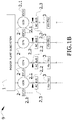
- FIG. 1b shows a particular embodiment of the schematic ordinary radar electrical architecture in a normal mode.
- the electrical architecture shown in this figure comprises a power plant subsystem, preferably formed by four reciprocating engines (1) for producing mechanical power, which preferably are Auxiliary Power Units (APUs) such as diesel engines. Then, power plant subsystem is directly connected to four 115VAC or 230VAC generators (2).
- APUs Auxiliary Power Units
- each one of the four reciprocating engines (1) of the power plant subsystem comprises gearboxes to directly connect one generator (2) thereto each. Therefore, both the reciprocating engines (1) and the generators (2) will be understood as AC power sources.
- Figures 2a-2c show examples of degraded modes in the electrical architecture, also known as DC network, of Figure 1 a.
- Figure 2a shows the configuration of the electrical architecture if one reciprocating engine (1) has failed.
- the contactors (2.2) of the generator (2) affected by the reciprocating engine (1) failed are opened in order to remove the conducting path.
- the AC buses (2.3) affected are connected in parallel with their non-paired AC buses (2.3), i.e. with the AC buses (2.3) coming from the operative reciprocating engine (1).
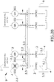
- Figure 2b shows the configuration of the electrical architecture if one generator (2) has failed. In this situation, the contactor (2.2) of the generator (2) failed is opened in order to remove its conducting path.
- the AC bus (2.3) affected is connected in parallel with its paired AC bus (2.3).
- Figure 2c shows the configuration of the electrical architecture if one AC/DC converter (3) has failed. In this situation, its AC/DC converter contactor (3.3) is opened in order to remove its conducting path towards the array (4).
- the array (4) affected is connected in parallel with its paired array (4).
- Figure 3 shows a schematic power distribution system (10) for a radar antenna according to the invention in a normal mode. As it can be seen, figure 3 only shows the electrical architecture from the AC/DC converters (3), while the previous architecture, in a particular embodiment, is the same as that shown in figure 1a . In another particular embodiment, the electrical architecture from the AC/DC converters (3) is the same as that shown in figure 1 b.
- the power distribution system (10) for a radar antenna (6) comprises:
- the power distribution system (10) comprises:
- each electrical load (5), or DC bus connected to comprises two inputs:
- connection between the AC/DC converter (3) and its corresponding electrical loads (5) is through a DC bus which comprises the first (5.1) and second (5.2) inputs.
- the AC/DC converters (3) being connected directly to its corresponding electrical loads (5), or by DC buses will be understood as a similar configuration.
- the electrical loads (5) are not intended to be connected in parallel as prior art does by the switching means (4.1) between paired arrays.
- Figures 4a and 4b show different configurations of the electrical architecture in the event one AC/DC converter (3) has failed, the system being in a degraded mode.
- the electrical loads (5) of the AC/DC converter (3) not failed are fed or energized maintaining the configuration shown in figure 3 , i.e. normal mode.
- said AC/DC converters (3) not failed uses theirs additional output (3.2) to support, in terms of electrical power, each one a particular electrical load (5) of the AC/DC converter (3) failed.
- the power distribution system is configured to continue supplying electrical power to the radar antenna in case of an AC/DC converter (3) is not energized and therefore not supplying electrical power to its corresponding electrical loads (5), such that the second input (5.2) of such electrical load (5) is connected to any additional output (3.2) of another AC/DC converter (3), being the first input (5.1) disconnected.
- each array (4) is energized with 65kW because the AC/DC converters are still feed with 87.5kW but they need to distribute among 4 electrical loads (5) instead of just its corresponding 3.
- 87.5kW/4 electrical loads ⁇ 21.6 kW and as each array is made of 3 electrical loads (5), each array (4) is energized with 65kW.
- 65kW ⁇ 4 arrays 260kW which is the total minimum electrical requirement of power supplied in degraded mode.
- Figure 4c shows schematically all the possible variants in connections of the additional output (3.2) of the AC/DC converters (3) to the electrical loads corresponding to other AC/DC converter (3). Therefore, any AC/DC converters (3) is able to support, feed or energize (understood as equivalent terms) an electrical load (5) corresponding to other AC/DC converter (3).
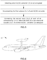
- Figure 5 shows a flowchart of the method for continuing supplying electrical power in a power distribution system (10) according to the invention.
- the power distribution system (10) has baseline architecture as that shown in figure 3 , and once the system switches to a degraded mode, the method comprises the following steps:
- Aircraft comprising a power distribution system
- FIG. 6 show a schematic view of an aircraft comprising a power distribution system (10) for DC network, such as a radar antenna (6), according to the invention.
- the radar antenna (6) comprising the plurality of electrical loads (5) gathered in arrays (4) is housed in a weatherproof dome in the top of the aircraft (11).
Landscapes
- Engineering & Computer Science (AREA)
- Power Engineering (AREA)
- Aviation & Aerospace Engineering (AREA)
- Mechanical Engineering (AREA)
- Direct Current Feeding And Distribution (AREA)
Abstract
Description
- The present invention belongs to the field of power distribution, in particular to the field of fail-safe reconfigurations using electronics architecture in the event of failure detected in power sources. More specifically, the invention is of special application in the aeronautic industry for powering electrical equipment such as electrical engines, radar antennas or any other DC (Direct Current) network boarded within the aircrafts.
- An Airborne Warning and Control System (also known as AWACS) is an airborne radar antenna picket system boarded in an aircraft and configured to detect objects in the vicinity. Such radar antenna system is an additional electrical system, in the form of a DC network, normally incorporated into a conventional aircraft architecture which further requires an increment of power generation.
- This increment of power generation required should be enough as to supply electrical power to such additional electrical system, a so-called DC network, incorporated in the conventional configuration of the aircraft.
- In this sense, the electrical power that the aircraft should provide is substantially doubled, up to an additional 400kW. Moreover, the power should be supplied, at least, as 270V Direct Current (DC) while the conventional configuration of the aircraft's electrical grid is around 28V (DC). All this leads to a major adaptation of the aircraft architecture.
- In ordinary radar electrical architecture, the radar antenna comprises a plurality of electrical loads gathered into four discrete load modules, each being fed by an autonomous AC power source. These AC power sources are connected somehow to AC/DC converters, i.e. electronic devices for converting electrical power from Alternating Current (AC) to Direct Current (DC) which afterwards feeds the electrical loads of the radar antenna.
- During operation, i.e. in normal mode, the total minimum electrical requirement of power supplied to the electrical loads is 350kW. However, with the failure of any of the AC power sources during operation, the AWACS electrical architecture switches to a degraded mode, being the total minimum electrical requirement of power supplied to all the electrical loads reduced up to 260kW. Therefore, a set of downstream electrical loads of said AC power sources failed are affected being not fed. Nevertheless, even those electrical loads affected must be fed somehow to keep the equipment services of the radar antenna still working during the mission.
- Furthermore, in this degraded mode, an AC/DC converter is not energized and therefore neither is its downstream electrical loads of the radar antenna. However, the conventional solutions known in the prior art relies in providing an additional AC power to supply or feed the electrical loads affected. Additionally, this solution provides oversizing AC/DC converters paralleling them to redistribute the electrical power to all the loads.
- Also, said providing of additional AC power may be both in terms of adding a new AC power source and/or oversizing the current ones which would require providing more than 166 kW of mechanical power in order to fulfil with degraded mode conditions. This amount is much higher than the required in normal mode, thus increasing fuel consumption, and increasing weight and volume of the AC power sources.
- This abovementioned oversizing of the AC/DC converters pose some problems as, for example, increasing the weight and volume of the AC/DC converters. Additionally, since the radar antenna requires a substantial high power level, the solution of paralleling the AC/DC converters energized to feed the electrical loads affected is a complex and risky solution that may produce unexpected and collateral drawbacks due to the high power level handled by the components.
- The present invention provides a solution for the aforementioned problems, by a power distribution system for a DC network, such as a radar antenna, according to
claim 1, a method for continuing supplying electrical power according toclaim 9, and an aircraft according toclaim 10. In dependent claims, preferred embodiments of the invention are defined. - In a first inventive aspect, the invention provides a power distribution system for a Direct Current (DC) network such as a radar antenna, wherein the DC network comprises a plurality of electrical loads, and the power distribution system being preferably boarded on an aircraft and comprising:
- ▪ a plurality of AC/DC converters for supplying electrical power to the DC network, and
- ▪ at least one Alternating Current power source for energizing the AC/DC converters,
- ▪ an "n" number of AC/DC converters, comprising each one an "(n-1)" number of first outputs and at least an additional output,
- ▪ an "(n-1)·n" number of electrical loads, each "(n-1)" electrical loads corresponding to one AC/DC converter, wherein each electrical load comprises two inputs:
- ∘ a first input for being connected with a corresponding first output of the corresponding AC/DC converter, and
- ∘ a second input for being connected with any of the additional outputs of the AC/DC converters,
- Throughout this entire document, a DC network according to the invention may be also an anti-pollution system, electrical engines, an electrical system measurement (ESM), or the like.
- Throughout this entire document, "n" will be understood as an integer, i.e. a number without a fractional component.
- According to the invention, an "(n-1)" number of electrical loads are configured to be fed with DC electrical power by a single AC/DC converter. In other words the lay-out of the electronic architecture is intended to connect the first input of each "(n-1)" electrical loads with one of the "(n-1)" output of the corresponding AC/DC converter in the normal mode and, therefore, the correspondence of an "(n-1)" number of electrical loads is to one AC/DC converter.
- Advantageously, this power distribution system avoids paralleling the AC/DC converters which is a complex and risky solution at the power level required by the DC network. For instance, for a radar antenna the power level required is normally within the range of 260-350kW.
- According to the invention, the power distribution system is configured to continue supplying electrical power to the DC network in case of an AC/DC converter is not energized. This scenario is known as degraded mode, being produced with the failure of any of the upstream AC power sources feeding said AC/DC converter.
- In this sense, the power distribution system according to the invention provides power redistribution among the electrical loads in a degraded mode. This power redistribution is achieved by power support of the energized AC/DC converters to the corresponding loads of the not energized AC/DC converter. Hence, the additional power needed to offset the not energized AC/DC converter is distributed by the energized AC/DC converters therefore handling less power each one and avoiding oversizing their upstream AC power sources.
- In a preferred embodiment, the DC network is a radar antenna. More preferably, the DC network is an Airborne Warning and Control System, i.e. an airborne radar antenna picket system boarded in an aircraft and configured to detect objects in the vicinity.
- In a preferred embodiment, the AC/DC converters are High Voltage-Transformer Rectifier Units (the so-called HV-TRU). The High Voltage-Transformer Rectifier Units comprises multiple outputs, which permits providing power to the electrical loads of an AC/DC converter not energized.
- In a particular embodiment, the at least one AC power source are two reciprocating engines, preferably two diesel engines, energizing each one two 115VAC or 230VAC generators which are configured to further energize each one a AC/DC converter.
- In this embodiment, the AC power sources failed in the degraded mode may be either any of the reciprocating engines or any of the four generators feeding each one an AC/DC converter.
- Preferably, the 115VAC or 230VAC generators are directly connected to the gearbox of the reciprocating engines and therefore operate at a variable frequency proportional to the engine speed. Advantageously, 115VAC or 230VAC are the two standard voltage levels normally used in aircrafts electrical architecture.
- In a particular embodiment, the at least one AC power source are four reciprocating engines, preferably four diesel engines, energizing each one a 115VAC or 230VAC generator which is configured to further energize each one an AC/DC converter.
- In a preferred embodiment, the "n" number of AC/DC converters is four. Therefore, the system comprises four AC/DC converters and three electrical loads connected thereto each.
- In a preferred embodiment, the power distribution system comprises "n" number of AC/DC converters, comprising each one three additional outputs.
- In a particular embodiment, each of the "(n-1)" electrical loads corresponding to one AC/DC converter is connected in an array.
- In a particular embodiment, each array connecting the "(n-1)" electrical loads in parallel is supplied:
- ▪ with 87.5 kW if all the AC/DC converters (3) are energized; or
- ▪ with 65 kW if any of the AC/DC converters (3) is not energized.
- Advantageously, this allows meeting the total minimum electrical requirement of power supplied to the electrical loads. Preferably being 350kW in normal mode and 260kW in degraded mode.
- In a particular embodiment, the "(n-1)·n" electrical loads operates at least at 270V Direct Current (DC).
- In a particular embodiment, the power distribution system further comprises, switching means for switching connections in case of an AC/DC converter is not energized, and an electronic controller configured to activate/deactivate the switching means.
- In a preferred embodiment, the switching means are contactors, automatisms, circuit breakers, relays, or the like. More preferably, the switching means are contactors.
- In a particular embodiment, the DC network, such as a radar antenna, comprising a plurality of electrical loads is housed in a weatherproof dome in the top of the aircraft.
- In a second inventive aspect, the invention provides a method for continuing supplying electrical power in a power distribution system for a DC network, such as a radar antenna, wherein the DC network comprises a plurality of electrical loads, and the power distribution system being preferably boarded on an aircraft and comprising:
- ▪ a plurality of AC/DC converters for supplying electrical power to the DC network, and
- ▪ at least one AC power source for energizing the AC/DC converters,
- ▪ an "n" number of AC/DC converters, comprising each one an "(n-1)" number of first outputs and at least an additional output,
- ▪ an "(n-1)·n" number of electrical loads, each "(n-1)" electrical loads corresponding to one AC/DC converter, wherein each electrical load comprises two inputs:
- ∘ a first input connected with a corresponding first output of the corresponding AC/DC converter, and
- ∘ a second input for being connected with any of the additional outputs of the AC/DC converters,
- a. disconnecting the first outputs of the AC/DC converter not energized, being its corresponding "(n-1)" electrical load not energized thereby; and
- b. connecting the second input of each of the corresponding "(n-1)" electrical loads to an additional output of another AC/DC converter energized.
- In a third inventive aspect, the invention provides an aircraft comprising the power distribution system according to any of the embodiments of the first inventive aspect.
- All the features described in this specification (including the claims, description and drawings) and/or all the steps of the described method can be combined in any combination, with the exception of combinations of such mutually exclusive features and/or steps.
- These and other characteristics and advantages of the invention will become clearly understood in view of the detailed description of the invention which becomes apparent from a preferred embodiment of the invention, given just as an example and not being limited thereto, with reference to the drawings.
- Figures 1a-1b
- These figures show schematic ordinary DC network in a normal mode.
- Figures 2a-2c
- These figures show a schematic ordinary DC network in degraded modes.
- Figure 3
- This figure shows a schematic power distribution system for a radar antenna according to the invention in a normal mode.
- Figures 4a-4b
- These figures show a schematic power distribution system for a radar antenna according to the invention in a degraded mode.
- Figures 4c
- This figure shows a schematic power distribution system for a radar antenna according to the invention comprising all the possible variants in connections.
- Figure 5
- This figure shows a flowchart of the method for continuing supplying electrical power in a power distribution system in a degraded mode according to the invention.
- Figure 6
- This figure show a schematic view of an aircraft comprising a power distribution system according to the invention.
- Firstly, it is to be noted that for illustrative purposes, only a radar electrical architecture, or radar DC network, will be described thereafter. Nevertheless, the DC network according to the invention may be also an anti-pollution system, electrical engines, an electrical system measurement (ESM), or the like. Therefore, the same electrical architecture or DC network described hereafter will also applies to the mentioned systems, indiscriminately.
-
Figure 1a shows a schematic ordinary radar electrical architecture, radar DC network, in a normal mode. As it was already mentioned, this mode takes place during aircraft operation, where all the components are full-operative and the total minimum electrical requirement of power supplied is 350kW. - The electrical architecture shown in this figure comprises two reciprocating engines (1) for producing mechanical power, which preferably are Auxiliary Power Units (APUs) such as diesel engines. Then, the reciprocating engines comprise gearboxes to directly connect two 115VAC or 230VAC generators (2) thereto each (1) and convert the mechanical power into Alternating Current (AC) electrical power. Therefore, both the reciprocating engines (1) and the generators (2) will be understood as AC power sources.
- Additionally, each generator (2) comprises a Generator Control Unit (GCU) (2.1) for supervising its associated downstream AC generating channel by a mechanism for switching by both removing or restoring the conducting path in a contactor (2.2) or switching means of the circuit.
- Throughout this entire document, a contactor will be understood as a switching means or an electrical component that can "make" or "break" an electrical circuit, interrupting the current (either AC or DC) or diverting it from one conductor to another. Similar terms may be automatisms, circuit breakers, relays, or the like.
- After each contactor (2.2) or switching means of the generators (2), there is an AC bus (2.3) which are connected both with its paired AC bus (2.3) coming from the same reciprocating engine (1), and with another AC bus (2.3) coming from the other reciprocating engine (1). The connection between AC buses (2.3) is through switching means for paralleling them in the event of an upstream failure.
- As can be seen in
figure 1 , each AC bus (2.3) is connected to an AC/DC converter (3); therefore each AC bus (2.3) works as a connection point between an AC/DC converter (3) and the AC power sources for energizing the AC/DC converter (3). - Then, these AC/DC converters (3) feed a radar antenna (6) which further comprises a plurality of electrical loads (5) gathered into four discrete arrays (4) or DC buses. Therefore, each array (4) is fed by a single AC/DC converter (3) by an AC/DC contactor (3.3). In addition, the arrays (4) or DC buses comprises a switching means (4.1) connecting the arrays (4) paired, this is to say, those coming from the same reciprocating engine (1).
-
Figure 1b shows a particular embodiment of the schematic ordinary radar electrical architecture in a normal mode. The electrical architecture shown in this figure comprises a power plant subsystem, preferably formed by four reciprocating engines (1) for producing mechanical power, which preferably are Auxiliary Power Units (APUs) such as diesel engines. Then, power plant subsystem is directly connected to four 115VAC or 230VAC generators (2). - Preferably, each one of the four reciprocating engines (1) of the power plant subsystem comprises gearboxes to directly connect one generator (2) thereto each. Therefore, both the reciprocating engines (1) and the generators (2) will be understood as AC power sources.
- Once it has been explained the ordinary radar electrical architecture in the normal mode,
Figures 2a-2c show examples of degraded modes in the electrical architecture, also known as DC network, ofFigure 1 a. -
Figure 2a shows the configuration of the electrical architecture if one reciprocating engine (1) has failed. In this situation, the contactors (2.2) of the generator (2) affected by the reciprocating engine (1) failed are opened in order to remove the conducting path. - To solve the continuing of power suppling to all the arrays (4) of the radar antenna (6), the AC buses (2.3) affected are connected in parallel with their non-paired AC buses (2.3), i.e. with the AC buses (2.3) coming from the operative reciprocating engine (1).
-
Figure 2b shows the configuration of the electrical architecture if one generator (2) has failed. In this situation, the contactor (2.2) of the generator (2) failed is opened in order to remove its conducting path. - To solve the continuing of power suppling, the AC bus (2.3) affected is connected in parallel with its paired AC bus (2.3).
-
Figure 2c shows the configuration of the electrical architecture if one AC/DC converter (3) has failed. In this situation, its AC/DC converter contactor (3.3) is opened in order to remove its conducting path towards the array (4). - To solve the continuing of power suppling, the array (4) affected is connected in parallel with its paired array (4).
- For illustrative purposes, only a limit number of references have been shown in the figures. Nevertheless, it can be easily deduced which reference corresponds to the features shown in the figures.
-
Figure 3 shows a schematic power distribution system (10) for a radar antenna according to the invention in a normal mode. As it can be seen,figure 3 only shows the electrical architecture from the AC/DC converters (3), while the previous architecture, in a particular embodiment, is the same as that shown infigure 1a . In another particular embodiment, the electrical architecture from the AC/DC converters (3) is the same as that shown infigure 1 b. - According to the invention, the power distribution system (10) for a radar antenna (6) comprises:
- ▪ a plurality of AC/DC converters (3) for supplying electrical power to the electrical loads (5) of the radar antenna (6) gathered in arrays (4), and
- ▪ at least one AC power source (1, 2) for energizing the AC/DC converters (3) (not shown in this figure).
- Also, as it can be seen in
figure 3 , the power distribution system (10) comprises: - ▪ an "n" number of AC/DC converters (3) being in this particular example "4", comprising each one an "(n-1)" number of first outputs (3.1) and at least an additional output (3.2), and
- ▪ an "(n-1) · n" number of electrical loads (5) being in this particular example "12", each "(n-1)" electrical loads (5) corresponding to one AC/DC converter (3).
- Besides, each electrical load (5), or DC bus connected to, comprises two inputs:
- ▪ a first input (5.1) connected with a corresponding first output (3.1) of the corresponding AC/DC converter (3); and
- ▪ a second input (5.2) disconnected.
- In this normal mode, each array (4) is energized with 87.5kW and, because of the power distribution system comprises four arrays (4), 87.5kW·4arrays = 350kW which is the total minimum electrical requirement of power supplied in normal mode.
- Preferably, the connection between the AC/DC converter (3) and its corresponding electrical loads (5) is through a DC bus which comprises the first (5.1) and second (5.2) inputs. Then, the AC/DC converters (3) being connected directly to its corresponding electrical loads (5), or by DC buses will be understood as a similar configuration.
- Unlike the ordinary radar electrical architecture; the electrical loads (5) are not intended to be connected in parallel as prior art does by the switching means (4.1) between paired arrays.
-
Figures 4a and4b show different configurations of the electrical architecture in the event one AC/DC converter (3) has failed, the system being in a degraded mode. - In this situation, to solve the continuing of power suppling, the two inputs of the corresponding or affected electrical loads (5) of the AC/DC converter (3) failed, are positioned as follows:
- ▪ the first input (5.1) disconnected; and
- ▪ a second input (5.2) connected with any of the additional outputs (3.2) of the AC/DC converters (3).
- As it can be seen, the electrical loads (5) of the AC/DC converter (3) not failed are fed or energized maintaining the configuration shown in
figure 3 , i.e. normal mode. However, said AC/DC converters (3) not failed uses theirs additional output (3.2) to support, in terms of electrical power, each one a particular electrical load (5) of the AC/DC converter (3) failed. - In other words, the power distribution system is configured to continue supplying electrical power to the radar antenna in case of an AC/DC converter (3) is not energized and therefore not supplying electrical power to its corresponding electrical loads (5), such that the second input (5.2) of such electrical load (5) is connected to any additional output (3.2) of another AC/DC converter (3), being the first input (5.1) disconnected.
- In this degraded mode, each array (4) is energized with 65kW because the AC/DC converters are still feed with 87.5kW but they need to distribute among 4 electrical loads (5) instead of just its corresponding 3. Hence, 87.5kW/4 electrical loads ≈ 21.6 kW and as each array is made of 3 electrical loads (5), each array (4) is energized with 65kW. Then, 65kW·4 arrays = 260kW which is the total minimum electrical requirement of power supplied in degraded mode.
-
Figure 4c shows schematically all the possible variants in connections of the additional output (3.2) of the AC/DC converters (3) to the electrical loads corresponding to other AC/DC converter (3). Therefore, any AC/DC converters (3) is able to support, feed or energize (understood as equivalent terms) an electrical load (5) corresponding to other AC/DC converter (3). - For illustrative purposes, only a limit number of references have been shown in the figures. Nevertheless, it can be easily deduced which reference corresponds to the features shown in the figures.
-
Figure 5 shows a flowchart of the method for continuing supplying electrical power in a power distribution system (10) according to the invention. In short, the power distribution system (10) has baseline architecture as that shown infigure 3 , and once the system switches to a degraded mode, the method comprises the following steps: - i. detecting which AC/DC converter (3) is not energized,
- ii. disconnecting the first outputs (3.1) of said AC/DC converter (3) not energized; and
- iii. connecting the second input (5.2) of each of its corresponding "(n-1)" electrical loads (5) to an additional output (3.2) of another AC/DC converter (3) energized.
-
Figure 6 show a schematic view of an aircraft comprising a power distribution system (10) for DC network, such as a radar antenna (6), according to the invention. As it can be seen, the radar antenna (6) comprising the plurality of electrical loads (5) gathered in arrays (4) is housed in a weatherproof dome in the top of the aircraft (11).
Claims (12)
- A power distribution system (10) for a Direct Current, DC, network such as a radar antenna (6), wherein the DC network comprises a plurality of electrical loads (5), and the power distribution system (10) being preferably boarded on an aircraft (11) and comprising:▪ a plurality of AC/DC converters (3) for supplying electrical power to the DC network, and▪ at least one Alternating Current (AC) power source (1, 2) for energizing the AC/DC converters (3),wherein the power distribution system comprises,▪ an "n" number of AC/DC converters (3), comprising each one an "(n-1)" number of first outputs (3.1) and at least an additional output (3.2),▪ an "(n-1) · n" number of electrical loads (5), each "(n-1)" electrical loads (5) corresponding to one AC/DC converter (3), wherein each electrical load (5) comprises two inputs:wherein∘ a first input (5.1) for being connected with a corresponding first output (3.1) of the corresponding AC/DC converter (3), and∘ a second input (5.2) for being connected with any of the additional outputs (3.2) of the AC/DC converters (3),
the power distribution system is configured to continue supplying electrical power to the DC network in case of an AC/DC converter (3) is not energized and therefore not supplying electrical power to its corresponding electrical loads (5), such that the second input (5.2) of such electrical load (5) is connected to any additional output (3.2) of another AC/DC converter (3), being the first input (5.1) disconnected. - The power distribution system according to claim 1, wherein the at least one AC power source (1, 2) are two reciprocating engines (1), preferably two diesel engines, energizing each one two 115V or 230 VAC generators (2) which are configured to further energize each one a AC/DC converter (3).
- The power distribution system according to claim 1, wherein the at least one AC power source (1,2) are four reciprocating engines (1), preferably four diesel engines, energizing each one a 115VAC or 230VAC generator (2) which is configured to further energize each one an AC/DC converter (3).
- The power distribution system according to any of the previous claims, wherein the "n" number of AC/DC converters (3) is four, the system comprising four AC/DC converters (3).
- The power distribution system according to any of the previous claims, wherein the power distribution system comprises "n" number of AC/DC converters (3), comprising each one three additional outputs (3.2).
- The power distribution system according to any of the previous claims, wherein each of the "(n-1)" electrical loads (5) corresponding to one AC/DC converter (3) are connected in an array (4).
- The power distribution system according to the previous claim, wherein each array (4) connecting the "(n-1)" electrical loads (5) is supplied:▪ with 87.5 kW if all the AC/DC converters (3) are energized; or▪ with 65 kW if any of the AC/DC converters (3) is not energized.
- The power distribution system according to any of the previous claims, wherein the "(n-1) x n" electrical loads (5) operates at least at 270V Direct Current (DC).
- The power distribution system according to any of the previous claims further comprising,▪ switching means for switching connections in case of an AC/DC converter (3) is not energized, and▪ an electronic controller configured to activate/deactivate the switching means.
- The power distribution system according to any of the previous claims, wherein the DC network, such as radar antenna (6), comprising a plurality of electrical loads (5) is housed in a weatherproof dome in the top of the aircraft (11).
- A method for continuing supplying electrical power in a power distribution system (10) for a DC network, such as a radar antenna (6), wherein the DC network comprises a plurality of electrical loads (5), and the power distribution system being preferably boarded on an aircraft (11) and comprising:▪ a plurality of AC/DC converters (3) for supplying electrical power to the DC network, and▪ at least one Alternating Current (AC) power source (1, 2) for energizing the AC/DC converters (3),wherein the power distribution system comprises,▪ an "n" number of AC/DC converters (3), comprising each one an "(n-1)" number of first outputs (3.1) and at least an additional output (3.2),▪ an "(n-1) · n" number of electrical loads (5), each "(n-1)" electrical loads (5) corresponding to one AC/DC converter (3), wherein each electrical load (5) comprises two inputs:wherein∘ a first input (5.1) connected with a corresponding first output (3.1) of the corresponding AC/DC converter (3), and∘ a second input (5.2) for being connected with any of the additional outputs (3.2) of the AC/DC converters (3),
when one of the AC/DC converter (3) is not energized, the method comprises the steps of:c. disconnecting the first outputs (3.1) of the AC/DC converter (3) not energized, being its corresponding "(n-1)" electrical load (5) not energized thereby; andd. connecting the second input (5.2) of each of the corresponding "(n-1)" electrical loads (5) to an additional output (3.2) of another AC/DC converter (3) energized. - An aircraft comprising the power distribution system according to any of claims 1 to 10.
Priority Applications (3)
| Application Number | Priority Date | Filing Date | Title |
|---|---|---|---|
| EP17382612.4A EP3457512B1 (en) | 2017-09-15 | 2017-09-15 | Power distribution system for dc network |
| ES17382612T ES2861584T3 (en) | 2017-09-15 | 2017-09-15 | Power distribution system for direct current network |
| US16/133,066 US11084598B2 (en) | 2017-09-15 | 2018-09-17 | Power distribution system for DC network |
Applications Claiming Priority (1)
| Application Number | Priority Date | Filing Date | Title |
|---|---|---|---|
| EP17382612.4A EP3457512B1 (en) | 2017-09-15 | 2017-09-15 | Power distribution system for dc network |
Publications (2)
| Publication Number | Publication Date |
|---|---|
| EP3457512A1 true EP3457512A1 (en) | 2019-03-20 |
| EP3457512B1 EP3457512B1 (en) | 2021-02-24 |
Family
ID=59901462
Family Applications (1)
| Application Number | Title | Priority Date | Filing Date |
|---|---|---|---|
| EP17382612.4A Active EP3457512B1 (en) | 2017-09-15 | 2017-09-15 | Power distribution system for dc network |
Country Status (3)
| Country | Link |
|---|---|
| US (1) | US11084598B2 (en) |
| EP (1) | EP3457512B1 (en) |
| ES (1) | ES2861584T3 (en) |
Cited By (1)
| Publication number | Priority date | Publication date | Assignee | Title |
|---|---|---|---|---|
| CN115912485A (en) * | 2022-12-12 | 2023-04-04 | 中国商用飞机有限责任公司 | All-electric aircraft power and on-board power systems and related power systems |
Families Citing this family (5)
| Publication number | Priority date | Publication date | Assignee | Title |
|---|---|---|---|---|
| EP3560059A1 (en) * | 2016-12-21 | 2019-10-30 | Single Buoy Moorings, Inc. | Power generation and distribution arrangement and floating unit comprising such an arrangement |
| GB2574039B (en) * | 2018-05-24 | 2021-04-14 | Caterpillar Inc | A power distribution system for a marine vessel |
| FR3095422B1 (en) * | 2019-04-25 | 2022-01-21 | Safran Helicopter Engines | AIRCRAFT ELECTRICAL POWER SUPPLY NETWORK |
| US12529756B2 (en) * | 2021-06-24 | 2026-01-20 | Raytheon Company | Composable radar |
| GB2613787A (en) * | 2021-12-14 | 2023-06-21 | Rolls Royce Plc | Aircraft power and propulsion system |
Citations (7)
| Publication number | Priority date | Publication date | Assignee | Title |
|---|---|---|---|---|
| EP0150853A2 (en) * | 1984-02-02 | 1985-08-07 | Thomson-Csf Telephone | Electric power supply device |
| EP0685917A1 (en) * | 1994-05-31 | 1995-12-06 | Alcatel Cit | Secure power supply |
| US20020175567A1 (en) * | 2001-03-30 | 2002-11-28 | Thierry Marin-Martinod | Power management installation in an aircraft |
| US20050177756A1 (en) * | 2004-02-11 | 2005-08-11 | Dobbs Robert W. | Power distribution system utilizing redundant AC sources or DC sources |
| US20080100136A1 (en) * | 2006-10-25 | 2008-05-01 | Airbus France | Power supply system and method on board an aircraft |
| US20100156187A1 (en) * | 2005-08-04 | 2010-06-24 | Aviem System Ltd | UPS System |
| US20130293012A1 (en) * | 2012-05-07 | 2013-11-07 | Korea Institute Of Energy Research | System and method for converting electric power, and apparatus and method for controlling the system |
-
2017
- 2017-09-15 ES ES17382612T patent/ES2861584T3/en active Active
- 2017-09-15 EP EP17382612.4A patent/EP3457512B1/en active Active
-
2018
- 2018-09-17 US US16/133,066 patent/US11084598B2/en active Active
Patent Citations (7)
| Publication number | Priority date | Publication date | Assignee | Title |
|---|---|---|---|---|
| EP0150853A2 (en) * | 1984-02-02 | 1985-08-07 | Thomson-Csf Telephone | Electric power supply device |
| EP0685917A1 (en) * | 1994-05-31 | 1995-12-06 | Alcatel Cit | Secure power supply |
| US20020175567A1 (en) * | 2001-03-30 | 2002-11-28 | Thierry Marin-Martinod | Power management installation in an aircraft |
| US20050177756A1 (en) * | 2004-02-11 | 2005-08-11 | Dobbs Robert W. | Power distribution system utilizing redundant AC sources or DC sources |
| US20100156187A1 (en) * | 2005-08-04 | 2010-06-24 | Aviem System Ltd | UPS System |
| US20080100136A1 (en) * | 2006-10-25 | 2008-05-01 | Airbus France | Power supply system and method on board an aircraft |
| US20130293012A1 (en) * | 2012-05-07 | 2013-11-07 | Korea Institute Of Energy Research | System and method for converting electric power, and apparatus and method for controlling the system |
Cited By (1)
| Publication number | Priority date | Publication date | Assignee | Title |
|---|---|---|---|---|
| CN115912485A (en) * | 2022-12-12 | 2023-04-04 | 中国商用飞机有限责任公司 | All-electric aircraft power and on-board power systems and related power systems |
Also Published As
| Publication number | Publication date |
|---|---|
| US11084598B2 (en) | 2021-08-10 |
| US20190118960A1 (en) | 2019-04-25 |
| ES2861584T3 (en) | 2021-10-06 |
| EP3457512B1 (en) | 2021-02-24 |
Similar Documents
| Publication | Publication Date | Title |
|---|---|---|
| US11084598B2 (en) | Power distribution system for DC network | |
| Nya et al. | Benefits of higher voltage levels in aircraft electrical power systems | |
| US9143029B2 (en) | System and method for power distribution | |
| US7800245B2 (en) | Method and architecture for reduction in vehicle wiring | |
| US11303121B2 (en) | Modular direct current (DC) architectures | |
| EP2945244A1 (en) | Power and data distribution module and method for power and data distribution in an airborne vehicle | |
| US10693314B2 (en) | Electric distribution architecture | |
| EP2442425A1 (en) | Electrical power control system for a vehicle. | |
| Armstrong et al. | Trade studies for NASA N3-X turboelectric distributed propulsion system electrical power system architecture | |
| EP3048689B1 (en) | Direct current power system | |
| US8148842B2 (en) | Electrical power generation system having multiple secondary power distribution assemblies with integral power conversion | |
| US20170225798A1 (en) | High-voltage direct current power supply system for an aircraft | |
| EP3176896A2 (en) | Power management and distribution system | |
| US9809321B2 (en) | Electrical power distribution system with localized distribution conversion units | |
| GB2559730A (en) | Power delivery system for multiple loads | |
| US10822116B2 (en) | Power distribution network | |
| EP2852020B1 (en) | Power distribution architecture and aircraft comprising power distribution architecture | |
| CN107399439B (en) | Power supply system with a multiphase generator and aircraft with such a power supply system | |
| US20190006852A1 (en) | Electrical power distribution box for onboard network of an aircraft and corresponding electrical power supply system | |
| EP0536736A1 (en) | Power supply and control device particularly for RF ion thrustors | |
| US10263431B2 (en) | Supply system for electronic boards of an electrical distribution system | |
| Schröter | Power Management on Aircraft–Wrap-up and Further Thinking | |
| Hegner et al. | THE INTEGRATED FIGHT THROUGH POWER FOR INTEGRATED POWER SYSTEM |
Legal Events
| Date | Code | Title | Description |
|---|---|---|---|
| PUAI | Public reference made under article 153(3) epc to a published international application that has entered the european phase |
Free format text: ORIGINAL CODE: 0009012 |
|
| STAA | Information on the status of an ep patent application or granted ep patent |
Free format text: STATUS: THE APPLICATION HAS BEEN PUBLISHED |
|
| AK | Designated contracting states |
Kind code of ref document: A1 Designated state(s): AL AT BE BG CH CY CZ DE DK EE ES FI FR GB GR HR HU IE IS IT LI LT LU LV MC MK MT NL NO PL PT RO RS SE SI SK SM TR |
|
| AX | Request for extension of the european patent |
Extension state: BA ME |
|
| STAA | Information on the status of an ep patent application or granted ep patent |
Free format text: STATUS: REQUEST FOR EXAMINATION WAS MADE |
|
| 17P | Request for examination filed |
Effective date: 20190913 |
|
| RBV | Designated contracting states (corrected) |
Designated state(s): AL AT BE BG CH CY CZ DE DK EE ES FI FR GB GR HR HU IE IS IT LI LT LU LV MC MK MT NL NO PL PT RO RS SE SI SK SM TR |
|
| STAA | Information on the status of an ep patent application or granted ep patent |
Free format text: STATUS: EXAMINATION IS IN PROGRESS |
|
| 17Q | First examination report despatched |
Effective date: 20200513 |
|
| REG | Reference to a national code |
Ref country code: DE Ref legal event code: R079 Ref document number: 602017033171 Country of ref document: DE Free format text: PREVIOUS MAIN CLASS: H02J0003000000 Ipc: H02J0001100000 |
|
| GRAP | Despatch of communication of intention to grant a patent |
Free format text: ORIGINAL CODE: EPIDOSNIGR1 |
|
| STAA | Information on the status of an ep patent application or granted ep patent |
Free format text: STATUS: GRANT OF PATENT IS INTENDED |
|
| RIC1 | Information provided on ipc code assigned before grant |
Ipc: H02J 3/00 20060101ALI20200909BHEP Ipc: H02J 1/10 20060101AFI20200909BHEP Ipc: B64C 1/36 20060101ALI20200909BHEP |
|
| INTG | Intention to grant announced |
Effective date: 20200924 |
|
| GRAS | Grant fee paid |
Free format text: ORIGINAL CODE: EPIDOSNIGR3 |
|
| GRAA | (expected) grant |
Free format text: ORIGINAL CODE: 0009210 |
|
| STAA | Information on the status of an ep patent application or granted ep patent |
Free format text: STATUS: THE PATENT HAS BEEN GRANTED |
|
| AK | Designated contracting states |
Kind code of ref document: B1 Designated state(s): AL AT BE BG CH CY CZ DE DK EE ES FI FR GB GR HR HU IE IS IT LI LT LU LV MC MK MT NL NO PL PT RO RS SE SI SK SM TR |
|
| REG | Reference to a national code |
Ref country code: CH Ref legal event code: EP |
|
| REG | Reference to a national code |
Ref country code: AT Ref legal event code: REF Ref document number: 1365693 Country of ref document: AT Kind code of ref document: T Effective date: 20210315 |
|
| REG | Reference to a national code |
Ref country code: IE Ref legal event code: FG4D |
|
| REG | Reference to a national code |
Ref country code: DE Ref legal event code: R096 Ref document number: 602017033171 Country of ref document: DE |
|
| REG | Reference to a national code |
Ref country code: LT Ref legal event code: MG9D |
|
| REG | Reference to a national code |
Ref country code: NL Ref legal event code: MP Effective date: 20210224 |
|
| PG25 | Lapsed in a contracting state [announced via postgrant information from national office to epo] |
Ref country code: LT Free format text: LAPSE BECAUSE OF FAILURE TO SUBMIT A TRANSLATION OF THE DESCRIPTION OR TO PAY THE FEE WITHIN THE PRESCRIBED TIME-LIMIT Effective date: 20210224 Ref country code: BG Free format text: LAPSE BECAUSE OF FAILURE TO SUBMIT A TRANSLATION OF THE DESCRIPTION OR TO PAY THE FEE WITHIN THE PRESCRIBED TIME-LIMIT Effective date: 20210524 Ref country code: PT Free format text: LAPSE BECAUSE OF FAILURE TO SUBMIT A TRANSLATION OF THE DESCRIPTION OR TO PAY THE FEE WITHIN THE PRESCRIBED TIME-LIMIT Effective date: 20210624 Ref country code: NO Free format text: LAPSE BECAUSE OF FAILURE TO SUBMIT A TRANSLATION OF THE DESCRIPTION OR TO PAY THE FEE WITHIN THE PRESCRIBED TIME-LIMIT Effective date: 20210524 Ref country code: GR Free format text: LAPSE BECAUSE OF FAILURE TO SUBMIT A TRANSLATION OF THE DESCRIPTION OR TO PAY THE FEE WITHIN THE PRESCRIBED TIME-LIMIT Effective date: 20210525 Ref country code: FI Free format text: LAPSE BECAUSE OF FAILURE TO SUBMIT A TRANSLATION OF THE DESCRIPTION OR TO PAY THE FEE WITHIN THE PRESCRIBED TIME-LIMIT Effective date: 20210224 Ref country code: HR Free format text: LAPSE BECAUSE OF FAILURE TO SUBMIT A TRANSLATION OF THE DESCRIPTION OR TO PAY THE FEE WITHIN THE PRESCRIBED TIME-LIMIT Effective date: 20210224 |
|
| REG | Reference to a national code |
Ref country code: AT Ref legal event code: MK05 Ref document number: 1365693 Country of ref document: AT Kind code of ref document: T Effective date: 20210224 |
|
| PG25 | Lapsed in a contracting state [announced via postgrant information from national office to epo] |
Ref country code: SE Free format text: LAPSE BECAUSE OF FAILURE TO SUBMIT A TRANSLATION OF THE DESCRIPTION OR TO PAY THE FEE WITHIN THE PRESCRIBED TIME-LIMIT Effective date: 20210224 Ref country code: PL Free format text: LAPSE BECAUSE OF FAILURE TO SUBMIT A TRANSLATION OF THE DESCRIPTION OR TO PAY THE FEE WITHIN THE PRESCRIBED TIME-LIMIT Effective date: 20210224 Ref country code: NL Free format text: LAPSE BECAUSE OF FAILURE TO SUBMIT A TRANSLATION OF THE DESCRIPTION OR TO PAY THE FEE WITHIN THE PRESCRIBED TIME-LIMIT Effective date: 20210224 Ref country code: RS Free format text: LAPSE BECAUSE OF FAILURE TO SUBMIT A TRANSLATION OF THE DESCRIPTION OR TO PAY THE FEE WITHIN THE PRESCRIBED TIME-LIMIT Effective date: 20210224 Ref country code: LV Free format text: LAPSE BECAUSE OF FAILURE TO SUBMIT A TRANSLATION OF THE DESCRIPTION OR TO PAY THE FEE WITHIN THE PRESCRIBED TIME-LIMIT Effective date: 20210224 |
|
| PG25 | Lapsed in a contracting state [announced via postgrant information from national office to epo] |
Ref country code: IS Free format text: LAPSE BECAUSE OF FAILURE TO SUBMIT A TRANSLATION OF THE DESCRIPTION OR TO PAY THE FEE WITHIN THE PRESCRIBED TIME-LIMIT Effective date: 20210624 |
|
| REG | Reference to a national code |
Ref country code: ES Ref legal event code: FG2A Ref document number: 2861584 Country of ref document: ES Kind code of ref document: T3 Effective date: 20211006 |
|
| PG25 | Lapsed in a contracting state [announced via postgrant information from national office to epo] |
Ref country code: AT Free format text: LAPSE BECAUSE OF FAILURE TO SUBMIT A TRANSLATION OF THE DESCRIPTION OR TO PAY THE FEE WITHIN THE PRESCRIBED TIME-LIMIT Effective date: 20210224 Ref country code: SM Free format text: LAPSE BECAUSE OF FAILURE TO SUBMIT A TRANSLATION OF THE DESCRIPTION OR TO PAY THE FEE WITHIN THE PRESCRIBED TIME-LIMIT Effective date: 20210224 Ref country code: CZ Free format text: LAPSE BECAUSE OF FAILURE TO SUBMIT A TRANSLATION OF THE DESCRIPTION OR TO PAY THE FEE WITHIN THE PRESCRIBED TIME-LIMIT Effective date: 20210224 Ref country code: EE Free format text: LAPSE BECAUSE OF FAILURE TO SUBMIT A TRANSLATION OF THE DESCRIPTION OR TO PAY THE FEE WITHIN THE PRESCRIBED TIME-LIMIT Effective date: 20210224 |
|
| REG | Reference to a national code |
Ref country code: DE Ref legal event code: R097 Ref document number: 602017033171 Country of ref document: DE |
|
| PG25 | Lapsed in a contracting state [announced via postgrant information from national office to epo] |
Ref country code: DK Free format text: LAPSE BECAUSE OF FAILURE TO SUBMIT A TRANSLATION OF THE DESCRIPTION OR TO PAY THE FEE WITHIN THE PRESCRIBED TIME-LIMIT Effective date: 20210224 Ref country code: RO Free format text: LAPSE BECAUSE OF FAILURE TO SUBMIT A TRANSLATION OF THE DESCRIPTION OR TO PAY THE FEE WITHIN THE PRESCRIBED TIME-LIMIT Effective date: 20210224 Ref country code: SK Free format text: LAPSE BECAUSE OF FAILURE TO SUBMIT A TRANSLATION OF THE DESCRIPTION OR TO PAY THE FEE WITHIN THE PRESCRIBED TIME-LIMIT Effective date: 20210224 |
|
| PLBE | No opposition filed within time limit |
Free format text: ORIGINAL CODE: 0009261 |
|
| STAA | Information on the status of an ep patent application or granted ep patent |
Free format text: STATUS: NO OPPOSITION FILED WITHIN TIME LIMIT |
|
| PG25 | Lapsed in a contracting state [announced via postgrant information from national office to epo] |
Ref country code: AL Free format text: LAPSE BECAUSE OF FAILURE TO SUBMIT A TRANSLATION OF THE DESCRIPTION OR TO PAY THE FEE WITHIN THE PRESCRIBED TIME-LIMIT Effective date: 20210224 |
|
| 26N | No opposition filed |
Effective date: 20211125 |
|
| PG25 | Lapsed in a contracting state [announced via postgrant information from national office to epo] |
Ref country code: SI Free format text: LAPSE BECAUSE OF FAILURE TO SUBMIT A TRANSLATION OF THE DESCRIPTION OR TO PAY THE FEE WITHIN THE PRESCRIBED TIME-LIMIT Effective date: 20210224 |
|
| REG | Reference to a national code |
Ref country code: DE Ref legal event code: R119 Ref document number: 602017033171 Country of ref document: DE |
|
| PG25 | Lapsed in a contracting state [announced via postgrant information from national office to epo] |
Ref country code: IT Free format text: LAPSE BECAUSE OF FAILURE TO SUBMIT A TRANSLATION OF THE DESCRIPTION OR TO PAY THE FEE WITHIN THE PRESCRIBED TIME-LIMIT Effective date: 20210224 |
|
| REG | Reference to a national code |
Ref country code: CH Ref legal event code: PL |
|
| REG | Reference to a national code |
Ref country code: BE Ref legal event code: MM Effective date: 20210930 |
|
| GBPC | Gb: european patent ceased through non-payment of renewal fee |
Effective date: 20210915 |
|
| PG25 | Lapsed in a contracting state [announced via postgrant information from national office to epo] |
Ref country code: IS Free format text: LAPSE BECAUSE OF FAILURE TO SUBMIT A TRANSLATION OF THE DESCRIPTION OR TO PAY THE FEE WITHIN THE PRESCRIBED TIME-LIMIT Effective date: 20210624 Ref country code: MC Free format text: LAPSE BECAUSE OF FAILURE TO SUBMIT A TRANSLATION OF THE DESCRIPTION OR TO PAY THE FEE WITHIN THE PRESCRIBED TIME-LIMIT Effective date: 20210224 |
|
| PG25 | Lapsed in a contracting state [announced via postgrant information from national office to epo] |
Ref country code: LU Free format text: LAPSE BECAUSE OF NON-PAYMENT OF DUE FEES Effective date: 20210915 Ref country code: IE Free format text: LAPSE BECAUSE OF NON-PAYMENT OF DUE FEES Effective date: 20210915 Ref country code: GB Free format text: LAPSE BECAUSE OF NON-PAYMENT OF DUE FEES Effective date: 20210915 Ref country code: DE Free format text: LAPSE BECAUSE OF NON-PAYMENT OF DUE FEES Effective date: 20220401 Ref country code: BE Free format text: LAPSE BECAUSE OF NON-PAYMENT OF DUE FEES Effective date: 20210930 |
|
| PG25 | Lapsed in a contracting state [announced via postgrant information from national office to epo] |
Ref country code: LI Free format text: LAPSE BECAUSE OF NON-PAYMENT OF DUE FEES Effective date: 20210930 Ref country code: CH Free format text: LAPSE BECAUSE OF NON-PAYMENT OF DUE FEES Effective date: 20210930 |
|
| PG25 | Lapsed in a contracting state [announced via postgrant information from national office to epo] |
Ref country code: CY Free format text: LAPSE BECAUSE OF FAILURE TO SUBMIT A TRANSLATION OF THE DESCRIPTION OR TO PAY THE FEE WITHIN THE PRESCRIBED TIME-LIMIT Effective date: 20210224 |
|
| PG25 | Lapsed in a contracting state [announced via postgrant information from national office to epo] |
Ref country code: HU Free format text: LAPSE BECAUSE OF FAILURE TO SUBMIT A TRANSLATION OF THE DESCRIPTION OR TO PAY THE FEE WITHIN THE PRESCRIBED TIME-LIMIT; INVALID AB INITIO Effective date: 20170915 |
|
| PG25 | Lapsed in a contracting state [announced via postgrant information from national office to epo] |
Ref country code: MK Free format text: LAPSE BECAUSE OF FAILURE TO SUBMIT A TRANSLATION OF THE DESCRIPTION OR TO PAY THE FEE WITHIN THE PRESCRIBED TIME-LIMIT Effective date: 20210224 |
|
| PG25 | Lapsed in a contracting state [announced via postgrant information from national office to epo] |
Ref country code: TR Free format text: LAPSE BECAUSE OF FAILURE TO SUBMIT A TRANSLATION OF THE DESCRIPTION OR TO PAY THE FEE WITHIN THE PRESCRIBED TIME-LIMIT Effective date: 20210224 |
|
| PG25 | Lapsed in a contracting state [announced via postgrant information from national office to epo] |
Ref country code: MT Free format text: LAPSE BECAUSE OF FAILURE TO SUBMIT A TRANSLATION OF THE DESCRIPTION OR TO PAY THE FEE WITHIN THE PRESCRIBED TIME-LIMIT Effective date: 20210224 |
|
| PGFP | Annual fee paid to national office [announced via postgrant information from national office to epo] |
Ref country code: FR Payment date: 20250922 Year of fee payment: 9 |
|
| PGFP | Annual fee paid to national office [announced via postgrant information from national office to epo] |
Ref country code: ES Payment date: 20251030 Year of fee payment: 9 |