EP3457387A1 - Location setting method - Google Patents
Location setting method Download PDFInfo
- Publication number
- EP3457387A1 EP3457387A1 EP18190448.3A EP18190448A EP3457387A1 EP 3457387 A1 EP3457387 A1 EP 3457387A1 EP 18190448 A EP18190448 A EP 18190448A EP 3457387 A1 EP3457387 A1 EP 3457387A1
- Authority
- EP
- European Patent Office
- Prior art keywords
- image forming
- portable terminal
- location
- information
- forming apparatus
- Prior art date
- Legal status (The legal status is an assumption and is not a legal conclusion. Google has not performed a legal analysis and makes no representation as to the accuracy of the status listed.)
- Withdrawn
Links
Images











Classifications
-
- H—ELECTRICITY
- H04—ELECTRIC COMMUNICATION TECHNIQUE
- H04W—WIRELESS COMMUNICATION NETWORKS
- H04W64/00—Locating users or terminals or network equipment for network management purposes, e.g. mobility management
- H04W64/003—Locating users or terminals or network equipment for network management purposes, e.g. mobility management locating network equipment
-
- H—ELECTRICITY
- H04—ELECTRIC COMMUNICATION TECHNIQUE
- H04W—WIRELESS COMMUNICATION NETWORKS
- H04W4/00—Services specially adapted for wireless communication networks; Facilities therefor
- H04W4/02—Services making use of location information
- H04W4/025—Services making use of location information using location based information parameters
-
- G—PHYSICS
- G09—EDUCATION; CRYPTOGRAPHY; DISPLAY; ADVERTISING; SEALS
- G09B—EDUCATIONAL OR DEMONSTRATION APPLIANCES; APPLIANCES FOR TEACHING, OR COMMUNICATING WITH, THE BLIND, DEAF OR MUTE; MODELS; PLANETARIA; GLOBES; MAPS; DIAGRAMS
- G09B29/00—Maps; Plans; Charts; Diagrams, e.g. route diagram
-
- G—PHYSICS
- G01—MEASURING; TESTING
- G01C—MEASURING DISTANCES, LEVELS OR BEARINGS; SURVEYING; NAVIGATION; GYROSCOPIC INSTRUMENTS; PHOTOGRAMMETRY OR VIDEOGRAMMETRY
- G01C21/00—Navigation; Navigational instruments not provided for in groups G01C1/00 - G01C19/00
- G01C21/10—Navigation; Navigational instruments not provided for in groups G01C1/00 - G01C19/00 by using measurements of speed or acceleration
- G01C21/12—Navigation; Navigational instruments not provided for in groups G01C1/00 - G01C19/00 by using measurements of speed or acceleration executed aboard the object being navigated; Dead reckoning
- G01C21/16—Navigation; Navigational instruments not provided for in groups G01C1/00 - G01C19/00 by using measurements of speed or acceleration executed aboard the object being navigated; Dead reckoning by integrating acceleration or speed, i.e. inertial navigation
- G01C21/165—Navigation; Navigational instruments not provided for in groups G01C1/00 - G01C19/00 by using measurements of speed or acceleration executed aboard the object being navigated; Dead reckoning by integrating acceleration or speed, i.e. inertial navigation combined with non-inertial navigation instruments
-
- G—PHYSICS
- G01—MEASURING; TESTING
- G01S—RADIO DIRECTION-FINDING; RADIO NAVIGATION; DETERMINING DISTANCE OR VELOCITY BY USE OF RADIO WAVES; LOCATING OR PRESENCE-DETECTING BY USE OF THE REFLECTION OR RERADIATION OF RADIO WAVES; ANALOGOUS ARRANGEMENTS USING OTHER WAVES
- G01S19/00—Satellite radio beacon positioning systems; Determining position, velocity or attitude using signals transmitted by such systems
- G01S19/38—Determining a navigation solution using signals transmitted by a satellite radio beacon positioning system
- G01S19/39—Determining a navigation solution using signals transmitted by a satellite radio beacon positioning system the satellite radio beacon positioning system transmitting time-stamped messages, e.g. GPS [Global Positioning System], GLONASS [Global Orbiting Navigation Satellite System] or GALILEO
- G01S19/42—Determining position
-
- G—PHYSICS
- G06—COMPUTING OR CALCULATING; COUNTING
- G06F—ELECTRIC DIGITAL DATA PROCESSING
- G06F3/00—Input arrangements for transferring data to be processed into a form capable of being handled by the computer; Output arrangements for transferring data from processing unit to output unit, e.g. interface arrangements
- G06F3/12—Digital output to print unit, e.g. line printer, chain printer
- G06F3/1201—Dedicated interfaces to print systems
- G06F3/1223—Dedicated interfaces to print systems specifically adapted to use a particular technique
- G06F3/1224—Client or server resources management
- G06F3/1226—Discovery of devices having required properties
-
- H—ELECTRICITY
- H04—ELECTRIC COMMUNICATION TECHNIQUE
- H04N—PICTORIAL COMMUNICATION, e.g. TELEVISION
- H04N1/00—Scanning, transmission or reproduction of documents or the like, e.g. facsimile transmission; Details thereof
- H04N1/00127—Connection or combination of a still picture apparatus with another apparatus, e.g. for storage, processing or transmission of still picture signals or of information associated with a still picture
- H04N1/00281—Connection or combination of a still picture apparatus with another apparatus, e.g. for storage, processing or transmission of still picture signals or of information associated with a still picture with a telecommunication apparatus, e.g. a switched network of teleprinters for the distribution of text-based information, a selective call terminal
-
- H—ELECTRICITY
- H04—ELECTRIC COMMUNICATION TECHNIQUE
- H04N—PICTORIAL COMMUNICATION, e.g. TELEVISION
- H04N1/00—Scanning, transmission or reproduction of documents or the like, e.g. facsimile transmission; Details thereof
- H04N1/00127—Connection or combination of a still picture apparatus with another apparatus, e.g. for storage, processing or transmission of still picture signals or of information associated with a still picture
- H04N1/00281—Connection or combination of a still picture apparatus with another apparatus, e.g. for storage, processing or transmission of still picture signals or of information associated with a still picture with a telecommunication apparatus, e.g. a switched network of teleprinters for the distribution of text-based information, a selective call terminal
- H04N1/00315—Connection or combination of a still picture apparatus with another apparatus, e.g. for storage, processing or transmission of still picture signals or of information associated with a still picture with a telecommunication apparatus, e.g. a switched network of teleprinters for the distribution of text-based information, a selective call terminal with a radio transmission apparatus
-
- H—ELECTRICITY
- H04—ELECTRIC COMMUNICATION TECHNIQUE
- H04W—WIRELESS COMMUNICATION NETWORKS
- H04W4/00—Services specially adapted for wireless communication networks; Facilities therefor
- H04W4/30—Services specially adapted for particular environments, situations or purposes
- H04W4/33—Services specially adapted for particular environments, situations or purposes for indoor environments, e.g. buildings
-
- H—ELECTRICITY
- H04—ELECTRIC COMMUNICATION TECHNIQUE
- H04W—WIRELESS COMMUNICATION NETWORKS
- H04W64/00—Locating users or terminals or network equipment for network management purposes, e.g. mobility management
- H04W64/006—Locating users or terminals or network equipment for network management purposes, e.g. mobility management with additional information processing, e.g. for direction or speed determination
-
- G—PHYSICS
- G01—MEASURING; TESTING
- G01S—RADIO DIRECTION-FINDING; RADIO NAVIGATION; DETERMINING DISTANCE OR VELOCITY BY USE OF RADIO WAVES; LOCATING OR PRESENCE-DETECTING BY USE OF THE REFLECTION OR RERADIATION OF RADIO WAVES; ANALOGOUS ARRANGEMENTS USING OTHER WAVES
- G01S19/00—Satellite radio beacon positioning systems; Determining position, velocity or attitude using signals transmitted by such systems
- G01S19/01—Satellite radio beacon positioning systems transmitting time-stamped messages, e.g. GPS [Global Positioning System], GLONASS [Global Orbiting Navigation Satellite System] or GALILEO
- G01S19/13—Receivers
- G01S19/31—Acquisition or tracking of other signals for positioning
Definitions
- Embodiments described herein relate generally to a technique of easily setting location information to an image forming apparatus.
- One of the objects of the present invention is to improve prior art techniques and overcome at least some of the prior art problems as for instance above illustrated.
- a method for configuring an image forming apparatus using a portable terminal comprising:
- the location of the portable terminal is displayed on a map.
- the method according to the first aspect of the invention further comprises displaying coordinates of the location on the map.
- the method according to the first aspect of the invention further comprises displaying a list of maps, each corresponding to a different building name and floor level, wherein the map is selected from the list.
- the method according to the first aspect of the invention further comprises displaying on the operation panel a list of information about each of a plurality of image forming apparatuses, wherein the image forming apparatus is selected from the list.
- the method according to the first aspect of the invention further comprises the displaying comprising displaying on the operation panel a building name and a floor level.
- the method according to the first aspect of the invention further comprises the location is detected using a global positioning system (GPS) sensor or a geomagnetic sensor installed in the portable terminal.
- GPS global positioning system
- a portable terminal configured to communicate with a plurality of image forming apparatuses, comprising:
- the processor executes instructions to display the location of the portable terminal on a map.
- the processor executes instructions to display coordinates of the location on the map.
- the processor executes instructions to display a list of maps, each corresponding to a different building name and floor level, and the map is selected from the list.
- the processor executes instructions to display on the operation panel a list of information about each of a plurality of image forming apparatuses, and the image forming apparatus is selected from the list.
- the processor executes instructions to display on the operation panel a building name and a floor level.
- the senor is a global positioning system (GPS) sensor or a geomagnetic sensor.
- GPS global positioning system
- a non-transitory computer readable medium storing a program causing a computer to execute a method of configuring an image forming apparatus, said method comprising:
- the location of the portable terminal and coordinates of the location are displayed on a map.
- the method further comprises displaying a list of maps, each corresponding to a different building name and floor level, wherein the map is selected from the list.
- the method further comprises displaying on the operation panel a list of information about each of a plurality of image forming apparatuses, wherein the image forming apparatus is selected from the list.
- the displaying comprises displaying on the operation panel a building name and a floor level.
- the location is detected using a global positioning system (GPS) sensor or a geomagnetic sensor installed in the portable terminal.
- GPS global positioning system
- a non-transitory computer readable medium storing a program causing a computer to execute a method of configuring an image forming apparatus, the method having steps as herein described.
- a method for configuring an image forming apparatus using a portable terminal including the steps of detecting a location of the portable terminal, transmitting to a plurality of image forming apparatuses, including the image forming apparatus, a query for information about the image forming apparatuses, displaying an operation panel on the portable terminal indicating the location of the portable terminal with the information about the image forming apparatuses, accepting an operation on the operation panel to select the image forming apparatus, and transmitting information about the location to the image forming apparatus.
- position information of an image forming apparatus is easily set.
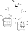
- FIG. 1 illustrates a system configuration example of an embodiment.
- a system 1 includes a plurality of image forming apparatuses 301 and 302, a portable terminal 100, and access points 201 and 202.
- FIG. 1 illustrates only the image forming apparatuses 301 and 302, but three or more image forming apparatuses may be disposed in respective floors of a building.
- FIG. 1 illustrates only the access points 201 and 202, but three or more access points may be disposed in the respective floors of the building.
- an image forming apparatus is described as an example of a device of which location information is set, but a device is not limited thereto.
- the portable terminal 100 has a network interface enabling wireless communication to be performed, and realizes each function by loading a program stored in a storage medium to a memory and a central processing unit (CPU) executing the program.
- CPU central processing unit
- the image forming apparatus 301 includes a scanning unit 315 which scans and reads a document sheet, a printing unit 316 which forms an image on a sheet, and a control unit 310.
- the control unit 310 is a unit which comprehensively controls each device of the image forming apparatus 301, and includes a processor 311, a subsidiary storage device 312, a network interface 313, and a memory 314.
- the processor 311 is, for example, a CPU, loads a program stored in the subsidiary storage device 312 into the memory 314, and performs calculation. Consequently, the processor 311 controls each device of the image forming apparatus 301.
- the subsidiary storage device 312 is a nonvolatile storage device, and is, for example, a hard disk drive (HDD) .
- the subsidiary storage device 312 stores image data read by the scanning unit 315 or image data transmitted from the outside, programs for executing calculation in the apparatus, and the like, in a nonvolatile manner.
- the memory 314 is a volatile main storage device, and stores execution programs or necessary data in a volatile manner.
- the network interface 313 transmits and receives data to and from other apparatuses via a wireless network based on the access points 201 and 202.
- the network interface 313 includes a unit performing short-range radio communication with other apparatuses.
- the network interface 313 includes, for example, a wireless communication mechanism based on the standard of IEEE 802.11 or a short-range radio communication mechanism based on the standard of IEEE 802.15.1. Units based on other wireless communication standards may be included.
- the image forming apparatus 302 has the same configuration, and includes a scanning unit 325, a printing unit 326 which forms an image on a sheet, and a control unit 320.
- the control unit 320 includes a processor 321, a subsidiary storage device 322, a network interface 323, and a memory 324.
- the image forming apparatus 301 will be focused, but the same applies to the image forming apparatus 302 or image forming apparatuses not illustrated in FIG. 1 .
- a user obtains location information by using a Global Positioning System (GPS) function of the portable terminal 100 in the vicinity of the image forming apparatuses 301 and 302. Thereafter, the location information is transmitted to the image forming apparatus by using a communication method such as Wi-Fi communication or USB communication.
- GPS Global Positioning System
- the system may include a server configured to communicate with the portable terminal.
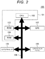
- FIG. 2 is a block diagram of the portable terminal 100 of an embodiment.
- a CPU 102, a read only memory (ROM) 103, a random access memory (RAM) 104, an external interface (I/F) 105, an operation panel 106, and a GPS sensor 107 are connected to each other via a system bus 108.
- the CPU 102, the ROM 103, and the RAM 104 form a control unit 101.
- the ROM 103 stores programs executed by the CPU 102 or threshold values in advance.
- the ROM 103 stores in advance a program for acquiring location information about the portable terminal 100 with the GPS sensor 107.
- the GPS sensor 107 acquires latitude, longitude, and altitude of the portable terminal 100.
- an example is description in which the GPS sensor is used as a sensor acquiring latitude, longitude, and altitude of the portable terminal 100, but this is only an example, and latitude, longitude, and altitude of the portable terminal 100 may be calculated by using information from, for example, a geomagnetic sensor, an acceleration sensor, a gyro sensor, and a pressure (atmospheric pressure) sensor.
- a location of the portable terminal 100 may be calculated on the basis of not only information from the GPS sensor 107 but also radio waves transmitted from the access points.
- a calculation method using a wireless LAN there is a Time-of-Arrive (TOA) method, a Time Difference of Arrival (TDOA) method, or a Received Signal Strength Indication (RSSI) method.
- TOA Time-of-Arrive
- TDOA Time Difference of Arrival
- RSSI Received Signal Strength Indication
- a location of the portable terminal 100 may be calculated by using a beacon method, an Ultra-wideband (UWB) method, an Indoor Messaging System (IMES) method, and other indoor positioning technique.
- UWB Ultra-wideband
- IMES Indoor Messaging System
- Various memory areas such as an area on which a program executed by the CPU 102 is loaded, and a work area used for the program to process data are dynamically formed in the RAM 104.
- the RAM 104 includes a map storage area in which map information including a floor map of each floor of a building and a corresponding map name is stored.
- the control unit 101 displays a floor map image on the basis of the map information stored in the map storage area.
- the map information stored in the map storage area is received from the outside via the external I/F 105.
- the map information includes information regarding latitude, longitude, and altitude (number of stories), corresponding to any location on a floor map.
- the RAM 104 has an access point storage area in which access point information is stored.
- the control unit 101 determines latitude, longitude, and altitude (in particular, floor level) at which the portable terminal 100 is present on the basis of the information stored in the access point storage area.
- the access point information stored in the access point storage area is received from the outside via the external I/F 105.
- the access point information includes an access point name, or information regarding latitude, longitude, and altitude at which an access point is located.
- the RAM 104 has a device storage area in which a device name is stored.
- the control unit 101 displays device information on the basis of the device information stored in the device storage area.
- the device information stored in the device storage area is received from the outside via the external I/F 105.
- the RAM 104 has a location storage area in which latitude, longitude, and altitude information about the current location of the portable terminal 100 are stored.
- Location information stored in the location storage area includes information acquired by the GPS sensor 107 or a location calculated on the basis of a location of the access point.
- the external I/F 105 is an interface for communicating with, for example, an external apparatus such as the image forming apparatus.
- the external I/F 105 may be an interface performing data communication with an external apparatus.
- the external I/F 105 may be a device (for example, a USB memory) which is locally connected to an external apparatus, and may be a network interface performing communication via a network.
- a data communication method may be Wi-Fi® communication or USB communication.
- the operation panel 106 is a user interface in which a display unit is integrally formed with a touch panel.
- the operation panel 106 has a display unit which is disposed on a front surface of a main body of the portable terminal 100 and is provided with a touch panel.
- the control unit 101 controls the content to be displayed on the display unit of the operation panel 106.
- the operation panel 106 outputs information which is input via the touch panel, to the control unit 101.
- Information regarding each process which is input from the operation panel 106 is stored in a predetermined region of the RAM 103 as process information. For example, to implement the above-described configuration, the portable terminal 100 displays a screen on the basis of a preset program.
- FIG. 3 is an operation screen displayed on the operation panel 106.
- a select button 106a is a button used for the user to select a device.
- a set button 106b is a button used for the user to set the location of the selected device.
- a device region 106c is a region in which devices which are selectable by the user and a device set by the user are displayed.
- "PRINTER A” is displayed in the device region 106c, and an IP address is also displayed.
- Location coordinates of the portable terminal 100 acquired by the GPS sensor 107 are displayed in a coordinate region 106d.
- “latitude 35.313553° and longitude 154.948788°” are displayed.
- the name of a map displayed in a map region 106f is displayed in a map name region 106e.
- “first building 4F" is displayed.
- the name of a map consists of a building and a floor name.
- a selected floor map is displayed in the map region 106f.
- Arrangement of desks in a floor is schematically illustrated in the map in FIG. 3 .
- a current location mark 106g as shown with a black circle in FIG. 3 is a mark for selecting a predetermined location on the map region 106f.
- a current location set button 106h is a button for a location of the current location mark 106g on the map region 106f to the current location.
- the current location of the portable terminal 100 is displayed on the map with the black circle. If an image forming apparatus is selected on the operation panel 106, latitude, longitude, and altitude can be set as location information about the image forming apparatus through simple tapping.
- FIG. 4 is a flowchart illustrating an operation example of displaying a screen on the operation panel of the portable terminal 100 in an embodiment.
- the control unit 101 of the portable terminal 100 displays the current location on the operation panel 106 (ACT 100).
- the control unit 101 displays device information about image forming apparatuses on the operation panel 106 (ACT 200).
- the control unit 101 displays the select button 106a, the set button 106b, and the current location set button 106h on the operation panel 106 (ACT 300).
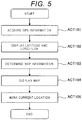
- FIG. 5 is a flowchart illustrating details of the operation (ACT 100) of displaying the current location.
- the control unit 101 of the portable terminal 100 acquires location information about the portable terminal 100 from the GPS sensor 107 (ACT 101).
- the control unit 101 displays latitude and longitude in the acquired location information about the portable terminal 100 in the coordinate region 106d of the operation panel 106 (ACT 102).
- the control unit 101 determines latitude, longitude, and the number of floors or stories of a building at which the portable terminal 100 is currently located on the basis of location information from the connected access points 201 and 202 or the GPS sensor, and reads floor map information corresponding to the latitude, the longitude, and the number of stories of the building (ACT 103).
- control unit 101 may read the floor map information about buildings located within a predetermined distance from the detected location.
- the control unit 101 displays a map name in the map name region 106e of the operation panel 106 on the basis of the read map information, and displays a floor map in the map region 106f of the operation panel 106 (ACT 104) .
- the control unit 101 displays the current location mark 106g at a location corresponding to the location information from the connected access points 201 and 202 or the GPS sensor 107 on the map displayed in the map region 106f of the operation panel 106 (ACT 105).
- FIG. 6 is a flowchart illustrating details of the operation (ACT 200) of displaying the device information.
- the control unit 101 of the portable terminal 100 transmits queries of Multicast Domain Name System (mDNS) to the image forming apparatuses 301 and 302 via the access points 201 and 202 by using the external I/F 105 (ACT 201). Protocols other than mDNS may be used for locating an image forming apparatus in the network.
- the control unit 101 receives responses of mDNS from the image forming apparatuses (ACT 202) .
- the control unit 101 adds the received names of the image forming apparatuses to the arrangement of the device information, and stores the names (ACT 203).
- the control unit 101 displays the name of an image forming apparatus in the first arrangement of the device information in the device region 106c of the operation panel 106 (ACT 204).
- a device name and address are automatically retrieved by using the mDNS technique.
- the mDNS technique such device information present on a subnet which is different from that of a portable terminal cannot be automatically retrieved.
- a user may directly input and register an IP address or a host name with respect to a device present on a subnet which is different from that of a portable terminal. If an IP address is input, a printer may be accessed with the IP address as a destination without change. If a host name is input, a DNS server is inquired about an IP address, and then a printer is accessed.
- FIG. 7 is a flowchart illustrating an operation example during map changing.
- the control unit 101 displays stored names of maps in the map name region 106e of the display unit 106 in a list form (ACT 401).
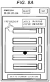
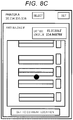
- FIG. 8B if the user touches "first building 3F" of the list displayed in the map name region 106e on the display unit 106 of the portable terminal 100 so as to select a map, the control unit 101 displays the selected map of "first building 3F" in the map region 106f (ACT 402).
- FIG. 8C the control unit 101 moves the current location mark 106g to the current location in the changed map (ACT 403).
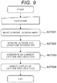
- FIG. 9 is a flowchart illustrating an operation example during current location changing.
- the control unit 101 moves the current location mark 106g to the touched location in the map region 106f as illustrated in FIG. 10B (ACT 501).
- the control unit 101 acquires latitude, longitude, and altitude information about the touched location from the map (ACT 502) .
- the control unit 101 overwrites the acquired latitude, longitude and altitude on the current latitude, longitude and altitude (ACT 503).
- the control unit 101 updates the display of the latitude and the longitude in the coordinate region 106d (ACT 504).
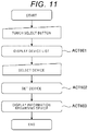
- FIG. 11 is a flowchart illustrating an operation example during device changing in the portable terminal. As illustrated in FIG. 12A , if the user touches the select button 106a on the display unit 106 of the portable terminal 100, the control unit 101 displays devices included in the arrangement in the device region 106c in a list form (ACT 601).
- the control unit 101 sets the selected device as a communication target device (ACT 602). As illustrated in FIG. 12C , the control unit 101 displays information regarding the communication target device in the device region 106c (ACT 603).
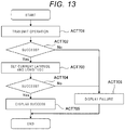
- FIG. 13 is a flowchart illustrating an operation of registering location information in the image forming apparatus (e.g., one of image forming apparatuses 301 and 302) .
- the control unit 101 of the portable terminal 100 transmits Get-Printer-Attributes operation of IPP to the image forming apparatus via the access point 201 or 202 by using the external I/F 105 (ACT 701).
- the control unit 101 checks whether a response of success is received from the image forming apparatus (ACT 702).
- the control unit 101 sets the current latitude, longitude and altitude in a geo-location in Set-Printer-Attributes of IPP, and transmits the geo-location to the image forming apparatus (ACT 703).
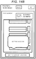
- the control unit 101 checks whether a response of success is received from the image forming apparatus (ACT 704). If so, the control unit 101 displays setting success on the operation panel 106 as illustrated in FIG. 14B (ACT 705). If there no response of success in ACTs 702 and 704, as illustrated in FIG. 14C , the control unit 101 displays setting failure on the operation panel 106 (ACT 706).
Landscapes
- Engineering & Computer Science (AREA)
- Computer Networks & Wireless Communication (AREA)
- Signal Processing (AREA)
- Physics & Mathematics (AREA)
- Radar, Positioning & Navigation (AREA)
- Remote Sensing (AREA)
- Theoretical Computer Science (AREA)
- General Physics & Mathematics (AREA)
- Human Computer Interaction (AREA)
- Business, Economics & Management (AREA)
- Educational Administration (AREA)
- Educational Technology (AREA)
- Multimedia (AREA)
- Mathematical Physics (AREA)
- General Engineering & Computer Science (AREA)
- Automation & Control Theory (AREA)
- Telephone Function (AREA)
- Telephonic Communication Services (AREA)
- User Interface Of Digital Computer (AREA)
- Accessory Devices And Overall Control Thereof (AREA)
- Facsimiles In General (AREA)
Abstract
A method for configuring an image forming apparatus using a portable terminal, includes the steps of detecting a location of the portable terminal, transmitting to a plurality of image forming apparatuses, including the image forming apparatus, a query for information about the image forming apparatuses, displaying an operation panel on the portable terminal indicating the location of the portable terminal with the information about the image forming apparatuses, accepting an operation on the operation panel to select the image forming apparatus, and transmitting information about the location to the image forming apparatus.
Description
- This application is based upon and claims the benefit of priority from Japanese Patent Application No.
2017-177738, filed September 15, 2017 - Embodiments described herein relate generally to a technique of easily setting location information to an image forming apparatus.
- In the related art, there is a technique for dynamically changing configurations of an image forming apparatus based on a distance between a user and the image forming apparatus to improve the usability of the image forming apparatus.
- One of the objects of the present invention is to improve prior art techniques and overcome at least some of the prior art problems as for instance above illustrated.
- According to a first aspect of the present invention, it is provided a method for configuring an image forming apparatus using a portable terminal, comprising:
- detecting a location of the portable terminal;
- transmitting to a plurality of image forming apparatuses, including the image forming apparatus, a query for information about the image forming apparatuses;
- displaying an operation panel on the portable terminal indicating the location of the portable terminal with the information about the image forming apparatuses;
- accepting an operation on the operation panel to select the image forming apparatus; and
- transmitting information about the location to the image forming apparatus.
- Optionally, in the method according to the first aspect of the invention, the location of the portable terminal is displayed on a map.
- Optionally, the method according to the first aspect of the invention further comprises displaying coordinates of the location on the map.
- Optionally, the method according to the first aspect of the invention further comprises displaying a list of maps, each corresponding to a different building name and floor level, wherein the map is selected from the list.
- Optionally, the method according to the first aspect of the invention further comprises displaying on the operation panel a list of information about each of a plurality of image forming apparatuses, wherein the image forming apparatus is selected from the list.
- Optionally, the method according to the first aspect of the invention further comprises the displaying comprising displaying on the operation panel a building name and a floor level.
- Optionally, the method according to the first aspect of the invention further comprises the location is detected using a global positioning system (GPS) sensor or a geomagnetic sensor installed in the portable terminal.
- According to a second aspect of the present invention, it is provided a portable terminal configured to communicate with a plurality of image forming apparatuses, comprising:
- a sensor configured to detect a location of the portable terminal;
- a touch panel (though the aspect and the present disclosure are not limited to a touch panel, as in fact other panels can be used) configured to accept an operation; and
- a processor configured to execute instructions to:
- transmit to each of the image forming apparatuses a query for information about the image forming apparatus;
- display an operation panel on the touch panel indicating the location of the portable terminal with the information about at least one of the image forming apparatuses; and
- transmit information about the location to one of the image forming apparatuses selected by an operation on the touch panel.
- Optionally, in the portable terminal according to the second aspect of the invention, the processor executes instructions to display the location of the portable terminal on a map.
- Optionally, in the portable terminal according to the second aspect of the invention, the processor executes instructions to display coordinates of the location on the map.
- Optionally, in the portable terminal according to the second aspect of the invention the processor executes instructions to display a list of maps, each corresponding to a different building name and floor level, and the map is selected from the list.
- Optionally, in the portable terminal according to the second aspect of the invention, the processor executes instructions to display on the operation panel a list of information about each of a plurality of image forming apparatuses, and the image forming apparatus is selected from the list.
- Optionally, in the portable terminal according to the second aspect of the invention, the processor executes instructions to display on the operation panel a building name and a floor level.
- Optionally, in the portable terminal according to the second aspect of the invention, the sensor is a global positioning system (GPS) sensor or a geomagnetic sensor.
- According to a third aspect of the present invention, it is provided a non-transitory computer readable medium storing a program causing a computer to execute a method of configuring an image forming apparatus, said method comprising:
- detecting a location of the portable terminal;
- transmitting to a plurality of image forming apparatuses, including the image forming apparatus, a query for information about the image forming apparatuses;
- displaying an operation panel on the portable terminal indicating the location of the portable terminal with the information about the image forming apparatuses;
- accepting an operation on the operation panel to select the image forming apparatus; and
- transmitting information about the location to the image forming apparatus.
- Optionally, in the medium according to the third aspect of the invention, the location of the portable terminal and coordinates of the location are displayed on a map. Optionally, in the medium according to the third aspect of the invention, the method further comprises displaying a list of maps, each corresponding to a different building name and floor level, wherein the map is selected from the list.
- Optionally, in the medium according to the third aspect of the invention, the method further comprises displaying on the operation panel a list of information about each of a plurality of image forming apparatuses, wherein the image forming apparatus is selected from the list.
- Optionally, in the medium according to the third aspect of the invention, the displaying comprises displaying on the operation panel a building name and a floor level.
- Optionally, in the medium according to the third aspect of the invention, the location is detected using a global positioning system (GPS) sensor or a geomagnetic sensor installed in the portable terminal.
- In general, it is provided a non-transitory computer readable medium storing a program causing a computer to execute a method of configuring an image forming apparatus, the method having steps as herein described.
-
-
FIG. 1 is a diagram illustrating a system configuration example. -
FIG. 2 is a block diagram of a portable terminal. -
FIG. 3 is a diagram illustrating an operation screen displayed on an operation panel. -
FIG. 4 is a flowchart illustrating screen display. -
FIG. 5 is a flowchart illustrating current location display. -
FIG. 6 is a flowchart illustrating device information display. -
FIG. 7 is a flowchart illustrating map changing. -
FIG. 8A is a diagram illustrating screen transition during map changing. -
FIG. 8B is a diagram illustrating screen transition. -
FIG. 8C is a diagram illustrating screen transition. -
FIG. 9 is a flowchart illustrating current location changing. -
FIG. 10A is a diagram illustrating screen transition during current location changing. -
FIG. 10B is a diagram illustrating screen transition. -
FIG. 11 is a flowchart illustrating device changing. -
FIG. 12A is a diagram illustrating screen transition during device changing. -
FIG. 12B is a diagram illustrating screen transition. -
FIG. 12C is a diagram illustrating screen transition. -
FIG. 13 is a flowchart illustrating location information registration. -
FIG. 14A is a diagram illustrating screen transition during location information registration. -
FIG. 14B is a diagram illustrating screen transition. -
FIG. 14C is a diagram illustrating screen transition. - According to an embodiment, there is provided a method for configuring an image forming apparatus using a portable terminal including the steps of detecting a location of the portable terminal, transmitting to a plurality of image forming apparatuses, including the image forming apparatus, a query for information about the image forming apparatuses, displaying an operation panel on the portable terminal indicating the location of the portable terminal with the information about the image forming apparatuses, accepting an operation on the operation panel to select the image forming apparatus, and transmitting information about the location to the image forming apparatus.
- According to the position setting method of an exemplary embodiment, position information of an image forming apparatus is easily set.
-
FIG. 1 illustrates a system configuration example of an embodiment. A system 1 includes a plurality ofimage forming apparatuses portable terminal 100, andaccess points FIG. 1 illustrates only theimage forming apparatuses FIG. 1 illustrates only theaccess points - The
portable terminal 100 has a network interface enabling wireless communication to be performed, and realizes each function by loading a program stored in a storage medium to a memory and a central processing unit (CPU) executing the program. - The
image forming apparatus 301 includes ascanning unit 315 which scans and reads a document sheet, aprinting unit 316 which forms an image on a sheet, and acontrol unit 310. Thecontrol unit 310 is a unit which comprehensively controls each device of theimage forming apparatus 301, and includes aprocessor 311, asubsidiary storage device 312, anetwork interface 313, and amemory 314. Theprocessor 311 is, for example, a CPU, loads a program stored in thesubsidiary storage device 312 into thememory 314, and performs calculation. Consequently, theprocessor 311 controls each device of theimage forming apparatus 301. - The
subsidiary storage device 312 is a nonvolatile storage device, and is, for example, a hard disk drive (HDD) . Thesubsidiary storage device 312 stores image data read by thescanning unit 315 or image data transmitted from the outside, programs for executing calculation in the apparatus, and the like, in a nonvolatile manner. Thememory 314 is a volatile main storage device, and stores execution programs or necessary data in a volatile manner. Thenetwork interface 313 transmits and receives data to and from other apparatuses via a wireless network based on theaccess points network interface 313 includes a unit performing short-range radio communication with other apparatuses. Thenetwork interface 313 includes, for example, a wireless communication mechanism based on the standard of IEEE 802.11 or a short-range radio communication mechanism based on the standard of IEEE 802.15.1. Units based on other wireless communication standards may be included. - The
image forming apparatus 302 has the same configuration, and includes ascanning unit 325, aprinting unit 326 which forms an image on a sheet, and acontrol unit 320. Thecontrol unit 320 includes aprocessor 321, asubsidiary storage device 322, anetwork interface 323, and amemory 324. In the following description, theimage forming apparatus 301 will be focused, but the same applies to theimage forming apparatus 302 or image forming apparatuses not illustrated inFIG. 1 . - In an embodiment, a user obtains location information by using a Global Positioning System (GPS) function of the
portable terminal 100 in the vicinity of theimage forming apparatuses - A description will be made of a configuration of a control system of the
portable terminal 100 carried by the user. Theportable terminal 100 is, for example, a smart phone, a tablet computer, or a notebook computer.FIG. 2 is a block diagram of theportable terminal 100 of an embodiment. ACPU 102, a read only memory (ROM) 103, a random access memory (RAM) 104, an external interface (I/F) 105, anoperation panel 106, and aGPS sensor 107 are connected to each other via asystem bus 108. TheCPU 102, theROM 103, and theRAM 104 form acontrol unit 101. - The
ROM 103 stores programs executed by theCPU 102 or threshold values in advance. TheROM 103 stores in advance a program for acquiring location information about theportable terminal 100 with theGPS sensor 107. TheGPS sensor 107 acquires latitude, longitude, and altitude of theportable terminal 100. - In an embodiment, an example is description in which the GPS sensor is used as a sensor acquiring latitude, longitude, and altitude of the
portable terminal 100, but this is only an example, and latitude, longitude, and altitude of theportable terminal 100 may be calculated by using information from, for example, a geomagnetic sensor, an acceleration sensor, a gyro sensor, and a pressure (atmospheric pressure) sensor. - A location of the
portable terminal 100 may be calculated on the basis of not only information from theGPS sensor 107 but also radio waves transmitted from the access points. As a calculation method using a wireless LAN, there is a Time-of-Arrive (TOA) method, a Time Difference of Arrival (TDOA) method, or a Received Signal Strength Indication (RSSI) method. A location of theportable terminal 100 may be calculated by using a beacon method, an Ultra-wideband (UWB) method, an Indoor Messaging System (IMES) method, and other indoor positioning technique. - Various memory areas such as an area on which a program executed by the
CPU 102 is loaded, and a work area used for the program to process data are dynamically formed in theRAM 104. - The
RAM 104 includes a map storage area in which map information including a floor map of each floor of a building and a corresponding map name is stored. Thecontrol unit 101 displays a floor map image on the basis of the map information stored in the map storage area. The map information stored in the map storage area is received from the outside via the external I/F 105. The map information includes information regarding latitude, longitude, and altitude (number of stories), corresponding to any location on a floor map. - The
RAM 104 has an access point storage area in which access point information is stored. Thecontrol unit 101 determines latitude, longitude, and altitude (in particular, floor level) at which theportable terminal 100 is present on the basis of the information stored in the access point storage area. The access point information stored in the access point storage area is received from the outside via the external I/F 105. The access point information includes an access point name, or information regarding latitude, longitude, and altitude at which an access point is located. - The
RAM 104 has a device storage area in which a device name is stored. Thecontrol unit 101 displays device information on the basis of the device information stored in the device storage area. The device information stored in the device storage area is received from the outside via the external I/F 105. - The
RAM 104 has a location storage area in which latitude, longitude, and altitude information about the current location of theportable terminal 100 are stored. Location information stored in the location storage area includes information acquired by theGPS sensor 107 or a location calculated on the basis of a location of the access point. - The external I/
F 105 is an interface for communicating with, for example, an external apparatus such as the image forming apparatus. The external I/F 105 may be an interface performing data communication with an external apparatus. For example, the external I/F 105 may be a device (for example, a USB memory) which is locally connected to an external apparatus, and may be a network interface performing communication via a network. A data communication method may be Wi-Fi® communication or USB communication. - The
operation panel 106 is a user interface in which a display unit is integrally formed with a touch panel. Theoperation panel 106 has a display unit which is disposed on a front surface of a main body of theportable terminal 100 and is provided with a touch panel. Thecontrol unit 101 controls the content to be displayed on the display unit of theoperation panel 106. Theoperation panel 106 outputs information which is input via the touch panel, to thecontrol unit 101. Information regarding each process which is input from theoperation panel 106 is stored in a predetermined region of theRAM 103 as process information. For example, to implement the above-described configuration, theportable terminal 100 displays a screen on the basis of a preset program. -
FIG. 3 is an operation screen displayed on theoperation panel 106. Aselect button 106a is a button used for the user to select a device. Aset button 106b is a button used for the user to set the location of the selected device. Adevice region 106c is a region in which devices which are selectable by the user and a device set by the user are displayed. InFIG. 3 , "PRINTER A" is displayed in thedevice region 106c, and an IP address is also displayed. Location coordinates of theportable terminal 100 acquired by theGPS sensor 107 are displayed in a coordinateregion 106d. InFIG. 3 , "latitude 35.313553° and longitude 154.948788°" are displayed. The name of a map displayed in amap region 106f is displayed in amap name region 106e. InFIG. 3 , "first building 4F" is displayed. In this example, the name of a map consists of a building and a floor name. A selected floor map is displayed in themap region 106f. Arrangement of desks in a floor is schematically illustrated in the map inFIG. 3 . Acurrent location mark 106g as shown with a black circle inFIG. 3 is a mark for selecting a predetermined location on themap region 106f. A current location setbutton 106h is a button for a location of thecurrent location mark 106g on themap region 106f to the current location. - As illustrated in
FIG. 3 , in an embodiment, the current location of theportable terminal 100 is displayed on the map with the black circle. If an image forming apparatus is selected on theoperation panel 106, latitude, longitude, and altitude can be set as location information about the image forming apparatus through simple tapping. -
FIG. 4 is a flowchart illustrating an operation example of displaying a screen on the operation panel of theportable terminal 100 in an embodiment. Thecontrol unit 101 of theportable terminal 100 displays the current location on the operation panel 106 (ACT 100). Next, thecontrol unit 101 displays device information about image forming apparatuses on the operation panel 106 (ACT 200). Next, thecontrol unit 101 displays theselect button 106a, theset button 106b, and the current location setbutton 106h on the operation panel 106 (ACT 300). -
FIG. 5 is a flowchart illustrating details of the operation (ACT 100) of displaying the current location. Thecontrol unit 101 of theportable terminal 100 acquires location information about the portable terminal 100 from the GPS sensor 107 (ACT 101). Thecontrol unit 101 displays latitude and longitude in the acquired location information about theportable terminal 100 in the coordinateregion 106d of the operation panel 106 (ACT 102). Thecontrol unit 101 determines latitude, longitude, and the number of floors or stories of a building at which theportable terminal 100 is currently located on the basis of location information from the connectedaccess points control unit 101 may read the floor map information about buildings located within a predetermined distance from the detected location. Thecontrol unit 101 displays a map name in themap name region 106e of theoperation panel 106 on the basis of the read map information, and displays a floor map in themap region 106f of the operation panel 106 (ACT 104) . Thecontrol unit 101 displays thecurrent location mark 106g at a location corresponding to the location information from the connectedaccess points GPS sensor 107 on the map displayed in themap region 106f of the operation panel 106 (ACT 105). -
FIG. 6 is a flowchart illustrating details of the operation (ACT 200) of displaying the device information. Thecontrol unit 101 of theportable terminal 100 transmits queries of Multicast Domain Name System (mDNS) to theimage forming apparatuses access points control unit 101 receives responses of mDNS from the image forming apparatuses (ACT 202) . Thecontrol unit 101 adds the received names of the image forming apparatuses to the arrangement of the device information, and stores the names (ACT 203). Thecontrol unit 101 displays the name of an image forming apparatus in the first arrangement of the device information in thedevice region 106c of the operation panel 106 (ACT 204). - In an embodiment, an example was described in which a device name and address are automatically retrieved by using the mDNS technique. In the mDNS technique, such device information present on a subnet which is different from that of a portable terminal cannot be automatically retrieved. Thus, a user may directly input and register an IP address or a host name with respect to a device present on a subnet which is different from that of a portable terminal. If an IP address is input, a printer may be accessed with the IP address as a destination without change. If a host name is input, a DNS server is inquired about an IP address, and then a printer is accessed.
-
FIG. 7 is a flowchart illustrating an operation example during map changing. As illustrated inFIG. 8A , if the user taps themap name region 106e on thedisplay unit 106 of theportable terminal 100, thecontrol unit 101 displays stored names of maps in themap name region 106e of thedisplay unit 106 in a list form (ACT 401). As illustrated inFIG. 8B , if the user touches "first building 3F" of the list displayed in themap name region 106e on thedisplay unit 106 of theportable terminal 100 so as to select a map, thecontrol unit 101 displays the selected map of "first building 3F" in themap region 106f (ACT 402). As illustrated inFIG. 8C , thecontrol unit 101 moves thecurrent location mark 106g to the current location in the changed map (ACT 403). -
FIG. 9 is a flowchart illustrating an operation example during current location changing. As illustrated inFIG. 10A , if the user touches themap region 106f on thedisplay unit 106 of theportable terminal 100, thecontrol unit 101 moves thecurrent location mark 106g to the touched location in themap region 106f as illustrated inFIG. 10B (ACT 501). Thecontrol unit 101 acquires latitude, longitude, and altitude information about the touched location from the map (ACT 502) . Thecontrol unit 101 overwrites the acquired latitude, longitude and altitude on the current latitude, longitude and altitude (ACT 503). As illustrated inFIG. 10B , thecontrol unit 101 updates the display of the latitude and the longitude in the coordinateregion 106d (ACT 504). -
FIG. 11 is a flowchart illustrating an operation example during device changing in the portable terminal. As illustrated inFIG. 12A , if the user touches theselect button 106a on thedisplay unit 106 of theportable terminal 100, thecontrol unit 101 displays devices included in the arrangement in thedevice region 106c in a list form (ACT 601). - As illustrated in
FIG. 12B , if the user touches "PRINTER B" of the list displayed in thedevice region 106c on thedisplay unit 106 of theportable terminal 100 so as to select the device, and touches theset button 106b, thecontrol unit 101 sets the selected device as a communication target device (ACT 602). As illustrated inFIG. 12C , thecontrol unit 101 displays information regarding the communication target device in thedevice region 106c (ACT 603). -
FIG. 13 is a flowchart illustrating an operation of registering location information in the image forming apparatus (e.g., one ofimage forming apparatuses 301 and 302) . If the current location setbutton 106h of theoperation panel 106 is touched (FIG. 14A ), thecontrol unit 101 of theportable terminal 100 transmits Get-Printer-Attributes operation of IPP to the image forming apparatus via theaccess point control unit 101 checks whether a response of success is received from the image forming apparatus (ACT 702). If so, thecontrol unit 101 sets the current latitude, longitude and altitude in a geo-location in Set-Printer-Attributes of IPP, and transmits the geo-location to the image forming apparatus (ACT 703). Thecontrol unit 101 checks whether a response of success is received from the image forming apparatus (ACT 704). If so, thecontrol unit 101 displays setting success on theoperation panel 106 as illustrated inFIG. 14B (ACT 705). If there no response of success in ACTs 702 and 704, as illustrated inFIG. 14C , thecontrol unit 101 displays setting failure on the operation panel 106 (ACT 706). - While certain embodiments have been described, these embodiments have been presented by way of example only, and are not intended to limit the scope of the inventions. Indeed, the novel embodiments described herein may be embodied in a variety of other forms; furthermore, various omissions, substitutions and changes in the form of the embodiments described herein may be made without departing from the spirit of the inventions. The accompanying claims and their equivalents are intended to cover such forms or modifications as would fall within the scope and spirit of the inventions.
Claims (15)
- A method for configuring an image forming apparatus using a portable terminal, comprising:detecting a location of the portable terminal;transmitting to a plurality of image forming apparatuses, including the image forming apparatus, a query for information about the image forming apparatuses;displaying an operation panel on the portable terminal indicating the location of the portable terminal with the information about the image forming apparatuses;accepting an operation on the operation panel to select the image forming apparatus; andtransmitting information about the location to the image forming apparatus.
- The method according to claim 1, wherein the location of the portable terminal is displayed on a map.
- The method according to claim 2, further comprising:displaying coordinates of the location on the map.
- The method according to any of claims 1 to 3, further comprising:displaying a list of maps, each corresponding to a different building name and floor level,wherein the map is selected from the list.
- The method according to any of claims 1 to 4, further comprising:displaying on the operation panel a list of information about each of a plurality of image forming apparatuses,wherein the image forming apparatus is selected from the list.
- The method according to any of claims 1 to 5, wherein the displaying comprises displaying on the operation panel a building name and a floor level.
- The method according to any of claims 1 to 6, wherein the location is detected using a global positioning system (GPS) sensor or a geomagnetic sensor installed in the portable terminal.
- A portable terminal configured to communicate with a plurality of image forming apparatuses, comprising:a sensor configured to detect a location of the portable terminal;a touch panel configured to accept an operation; anda processor configured to execute instructions to:transmit to each of the image forming apparatuses a query for information about the image forming apparatus;display an operation panel on the touch panel indicating the location of the portable terminal with the information about at least one of the image forming apparatuses; andtransmit information about the location to one of the image forming apparatuses selected by an operation on the touch panel.
- The portable terminal according to claim 8, wherein the processor executes instructions to display the location of the portable terminal on a map.
- The portable terminal according to claim 9, wherein the processor executes instructions to display coordinates of the location on the map.
- The portable terminal according to each of claims 8 to claim 10, wherein
the processor executes instructions to display a list of maps, each corresponding to a different building name and floor level, and
the map is selected from the list. - The portable terminal according to any of claims 8 to 11, wherein
the processor executes instructions to display on the operation panel a list of information about each of a plurality of image forming apparatuses, and
the image forming apparatus is selected from the list. - The portable terminal according to any of claims 8 to 12, wherein
the processor executes instructions to display on the operation panel a building name and a floor level. - The portable terminal according to any of claims 8 to 13, wherein
the sensor is a global positioning system (GPS) sensor or a geomagnetic sensor. - A non-transitory computer readable medium storing a program causing a computer to execute a method of configuring an image forming apparatus, said method comprising:detecting a location of the portable terminal;transmitting to a plurality of image forming apparatuses, including the image forming apparatus, a query for information about the image forming apparatuses;displaying an operation panel on the portable terminal indicating the location of the portable terminal with the information about the image forming apparatuses;accepting an operation on the operation panel to select the image forming apparatus; andtransmitting information about the location to the image forming apparatus.
Applications Claiming Priority (1)
| Application Number | Priority Date | Filing Date | Title |
|---|---|---|---|
| JP2017177738A JP2019051654A (en) | 2017-09-15 | 2017-09-15 | Position setting program and method |
Publications (1)
| Publication Number | Publication Date |
|---|---|
| EP3457387A1 true EP3457387A1 (en) | 2019-03-20 |
Family
ID=63556109
Family Applications (1)
| Application Number | Title | Priority Date | Filing Date |
|---|---|---|---|
| EP18190448.3A Withdrawn EP3457387A1 (en) | 2017-09-15 | 2018-08-23 | Location setting method |
Country Status (4)
| Country | Link |
|---|---|
| US (1) | US20190090217A1 (en) |
| EP (1) | EP3457387A1 (en) |
| JP (1) | JP2019051654A (en) |
| CN (1) | CN109525932A (en) |
Citations (1)
| Publication number | Priority date | Publication date | Assignee | Title |
|---|---|---|---|---|
| EP2377332A2 (en) * | 2008-12-16 | 2011-10-19 | LG Electronics Inc. | Mobile terminal and method of transferring or receiving data using the same |
Family Cites Families (3)
| Publication number | Priority date | Publication date | Assignee | Title |
|---|---|---|---|---|
| JP5926550B2 (en) * | 2011-12-07 | 2016-05-25 | キヤノン株式会社 | Printing system, information processing terminal, server, control method, and program |
| US8830512B2 (en) * | 2012-07-19 | 2014-09-09 | Xerox Corporation | Systems and methods for detecting a location of an image forming device using mobile device localization |
| US20140025374A1 (en) * | 2012-07-22 | 2014-01-23 | Xia Lou | Speech enhancement to improve speech intelligibility and automatic speech recognition |
-
2017
- 2017-09-15 JP JP2017177738A patent/JP2019051654A/en active Pending
-
2018
- 2018-07-25 CN CN201810829679.3A patent/CN109525932A/en active Pending
- 2018-08-06 US US16/055,517 patent/US20190090217A1/en not_active Abandoned
- 2018-08-23 EP EP18190448.3A patent/EP3457387A1/en not_active Withdrawn
Patent Citations (1)
| Publication number | Priority date | Publication date | Assignee | Title |
|---|---|---|---|---|
| EP2377332A2 (en) * | 2008-12-16 | 2011-10-19 | LG Electronics Inc. | Mobile terminal and method of transferring or receiving data using the same |
Also Published As
| Publication number | Publication date |
|---|---|
| JP2019051654A (en) | 2019-04-04 |
| US20190090217A1 (en) | 2019-03-21 |
| CN109525932A (en) | 2019-03-26 |
Similar Documents
| Publication | Publication Date | Title |
|---|---|---|
| US10057845B2 (en) | Control system for information processing apparatus using portable terminal, portable terminal, and control method and control program for information processing apparatus | |
| US9135530B2 (en) | Printer position determination and selection for a terminal apparatus and system | |
| US9137254B2 (en) | Local device awareness | |
| US10043314B2 (en) | Display control method and information processing apparatus | |
| US9949089B2 (en) | Position management system, position management apparatus, and position management method | |
| EP2878143B1 (en) | Location-based, virtual network computing-switching system | |
| EP3046348B1 (en) | Wireless relay device, and method for providing location information of wireless relay device | |
| US20150154482A1 (en) | Information processing apparatus, information processing method, and storage medium | |
| JP7006076B2 (en) | Information processing equipment, information processing systems and programs | |
| JP6789649B2 (en) | Communication devices, their control methods, and programs | |
| US20160284051A1 (en) | Display control method and information processing apparatus | |
| US9820092B1 (en) | Information processing apparatus, positioning system and method for positioning a communication device | |
| US20150168152A1 (en) | Methods and systems for use in indicating directions for direction finding systems | |
| US20180041873A1 (en) | Information processing apparatus and non-transitory computer readable medium | |
| JP2016071612A (en) | Layout plan creation system, layout plan creation device, and layout plan creation program | |
| US12067863B2 (en) | Remote control system using UWB and method of the same | |
| EP2664942A1 (en) | Methods and systems for use in selecting targets for direction finding systems | |
| US20210396543A1 (en) | Information processing apparatus, information processing method, and program | |
| JP2015152565A (en) | Electronics | |
| US20190090217A1 (en) | Location setting method | |
| US8285303B2 (en) | Area specifying apparatus, communication system, and area specifying method | |
| KR102401641B1 (en) | Mobile device and method for controlling the mobile device | |
| JP2015153116A (en) | Communication device | |
| JP6436002B2 (en) | Information processing apparatus and information processing program | |
| JP6540637B2 (en) | Communication system, communication apparatus, communication method |
Legal Events
| Date | Code | Title | Description |
|---|---|---|---|
| PUAI | Public reference made under article 153(3) epc to a published international application that has entered the european phase |
Free format text: ORIGINAL CODE: 0009012 |
|
| STAA | Information on the status of an ep patent application or granted ep patent |
Free format text: STATUS: THE APPLICATION HAS BEEN PUBLISHED |
|
| AK | Designated contracting states |
Kind code of ref document: A1 Designated state(s): AL AT BE BG CH CY CZ DE DK EE ES FI FR GB GR HR HU IE IS IT LI LT LU LV MC MK MT NL NO PL PT RO RS SE SI SK SM TR |
|
| AX | Request for extension of the european patent |
Extension state: BA ME |
|
| STAA | Information on the status of an ep patent application or granted ep patent |
Free format text: STATUS: THE APPLICATION IS DEEMED TO BE WITHDRAWN |
|
| 18D | Application deemed to be withdrawn |
Effective date: 20190921 |