EP3457217A1 - Toner case and image forming apparatus - Google Patents
Toner case and image forming apparatus Download PDFInfo
- Publication number
- EP3457217A1 EP3457217A1 EP18203400.9A EP18203400A EP3457217A1 EP 3457217 A1 EP3457217 A1 EP 3457217A1 EP 18203400 A EP18203400 A EP 18203400A EP 3457217 A1 EP3457217 A1 EP 3457217A1
- Authority
- EP
- European Patent Office
- Prior art keywords
- holder
- transmitter
- main body
- case main
- rotation axis
- Prior art date
- Legal status (The legal status is an assumption and is not a legal conclusion. Google has not performed a legal analysis and makes no representation as to the accuracy of the status listed.)
- Granted
Links
Images










Classifications
-
- G—PHYSICS
- G03—PHOTOGRAPHY; CINEMATOGRAPHY; ANALOGOUS TECHNIQUES USING WAVES OTHER THAN OPTICAL WAVES; ELECTROGRAPHY; HOLOGRAPHY
- G03G—ELECTROGRAPHY; ELECTROPHOTOGRAPHY; MAGNETOGRAPHY
- G03G15/00—Apparatus for electrographic processes using a charge pattern
- G03G15/06—Apparatus for electrographic processes using a charge pattern for developing
- G03G15/08—Apparatus for electrographic processes using a charge pattern for developing using a solid developer, e.g. powder developer
- G03G15/0822—Arrangements for preparing, mixing, supplying or dispensing developer
- G03G15/0865—Arrangements for supplying new developer
- G03G15/0867—Arrangements for supplying new developer cylindrical developer cartridges, e.g. toner bottles for the developer replenishing opening
- G03G15/087—Developer cartridges having a longitudinal rotational axis, around which at least one part is rotated when mounting or using the cartridge
- G03G15/0872—Developer cartridges having a longitudinal rotational axis, around which at least one part is rotated when mounting or using the cartridge the developer cartridges being generally horizontally mounted parallel to its longitudinal rotational axis
-
- G—PHYSICS
- G03—PHOTOGRAPHY; CINEMATOGRAPHY; ANALOGOUS TECHNIQUES USING WAVES OTHER THAN OPTICAL WAVES; ELECTROGRAPHY; HOLOGRAPHY
- G03G—ELECTROGRAPHY; ELECTROPHOTOGRAPHY; MAGNETOGRAPHY
- G03G15/00—Apparatus for electrographic processes using a charge pattern
- G03G15/06—Apparatus for electrographic processes using a charge pattern for developing
- G03G15/08—Apparatus for electrographic processes using a charge pattern for developing using a solid developer, e.g. powder developer
- G03G15/0822—Arrangements for preparing, mixing, supplying or dispensing developer
- G03G15/0865—Arrangements for supplying new developer
-
- G—PHYSICS
- G03—PHOTOGRAPHY; CINEMATOGRAPHY; ANALOGOUS TECHNIQUES USING WAVES OTHER THAN OPTICAL WAVES; ELECTROGRAPHY; HOLOGRAPHY
- G03G—ELECTROGRAPHY; ELECTROPHOTOGRAPHY; MAGNETOGRAPHY
- G03G15/00—Apparatus for electrographic processes using a charge pattern
- G03G15/06—Apparatus for electrographic processes using a charge pattern for developing
- G03G15/08—Apparatus for electrographic processes using a charge pattern for developing using a solid developer, e.g. powder developer
- G03G15/0822—Arrangements for preparing, mixing, supplying or dispensing developer
- G03G15/0865—Arrangements for supplying new developer
- G03G15/0875—Arrangements for supplying new developer cartridges having a box like shape
-
- G—PHYSICS
- G03—PHOTOGRAPHY; CINEMATOGRAPHY; ANALOGOUS TECHNIQUES USING WAVES OTHER THAN OPTICAL WAVES; ELECTROGRAPHY; HOLOGRAPHY
- G03G—ELECTROGRAPHY; ELECTROPHOTOGRAPHY; MAGNETOGRAPHY
- G03G21/00—Arrangements not provided for by groups G03G13/00 - G03G19/00, e.g. cleaning, elimination of residual charge
- G03G21/16—Mechanical means for facilitating the maintenance of the apparatus, e.g. modular arrangements
- G03G21/1642—Mechanical means for facilitating the maintenance of the apparatus, e.g. modular arrangements for connecting the different parts of the apparatus
- G03G21/1647—Mechanical connection means
-
- G—PHYSICS
- G03—PHOTOGRAPHY; CINEMATOGRAPHY; ANALOGOUS TECHNIQUES USING WAVES OTHER THAN OPTICAL WAVES; ELECTROGRAPHY; HOLOGRAPHY
- G03G—ELECTROGRAPHY; ELECTROPHOTOGRAPHY; MAGNETOGRAPHY
- G03G15/00—Apparatus for electrographic processes using a charge pattern
- G03G15/06—Apparatus for electrographic processes using a charge pattern for developing
- G03G15/08—Apparatus for electrographic processes using a charge pattern for developing using a solid developer, e.g. powder developer
- G03G15/0822—Arrangements for preparing, mixing, supplying or dispensing developer
- G03G15/0877—Arrangements for metering and dispensing developer from a developer cartridge into the development unit
- G03G15/0881—Sealing of developer cartridges
- G03G15/0886—Sealing of developer cartridges by mechanical means, e.g. shutter, plug
-
- G—PHYSICS
- G03—PHOTOGRAPHY; CINEMATOGRAPHY; ANALOGOUS TECHNIQUES USING WAVES OTHER THAN OPTICAL WAVES; ELECTROGRAPHY; HOLOGRAPHY
- G03G—ELECTROGRAPHY; ELECTROPHOTOGRAPHY; MAGNETOGRAPHY
- G03G15/00—Apparatus for electrographic processes using a charge pattern
- G03G15/06—Apparatus for electrographic processes using a charge pattern for developing
- G03G15/08—Apparatus for electrographic processes using a charge pattern for developing using a solid developer, e.g. powder developer
- G03G15/0822—Arrangements for preparing, mixing, supplying or dispensing developer
- G03G15/0887—Arrangements for conveying and conditioning developer in the developing unit, e.g. agitating, removing impurities or humidity
- G03G15/0889—Arrangements for conveying and conditioning developer in the developing unit, e.g. agitating, removing impurities or humidity for agitation or stirring
-
- G—PHYSICS
- G03—PHOTOGRAPHY; CINEMATOGRAPHY; ANALOGOUS TECHNIQUES USING WAVES OTHER THAN OPTICAL WAVES; ELECTROGRAPHY; HOLOGRAPHY
- G03G—ELECTROGRAPHY; ELECTROPHOTOGRAPHY; MAGNETOGRAPHY
- G03G15/00—Apparatus for electrographic processes using a charge pattern
- G03G15/06—Apparatus for electrographic processes using a charge pattern for developing
- G03G15/08—Apparatus for electrographic processes using a charge pattern for developing using a solid developer, e.g. powder developer
- G03G15/0822—Arrangements for preparing, mixing, supplying or dispensing developer
- G03G15/0887—Arrangements for conveying and conditioning developer in the developing unit, e.g. agitating, removing impurities or humidity
- G03G15/0891—Arrangements for conveying and conditioning developer in the developing unit, e.g. agitating, removing impurities or humidity for conveying or circulating developer, e.g. augers
-
- G—PHYSICS
- G03—PHOTOGRAPHY; CINEMATOGRAPHY; ANALOGOUS TECHNIQUES USING WAVES OTHER THAN OPTICAL WAVES; ELECTROGRAPHY; HOLOGRAPHY
- G03G—ELECTROGRAPHY; ELECTROPHOTOGRAPHY; MAGNETOGRAPHY
- G03G2215/00—Apparatus for electrophotographic processes
- G03G2215/06—Developing structures, details
- G03G2215/066—Toner cartridge or other attachable and detachable container for supplying developer material to replace the used material
- G03G2215/0663—Toner cartridge or other attachable and detachable container for supplying developer material to replace the used material having a longitudinal rotational axis, around which at least one part is rotated when mounting or using the cartridge
- G03G2215/0665—Generally horizontally mounting of said toner cartridge parallel to its longitudinal rotational axis
Definitions
- a toner case includes a case main body, a rotator, a transmitter and a moving mechanism.
- the case main body stores a toner.
- the rotator is stored in the case main body and rotates around a rotation axis.
- the transmitter is arranged outside the case main body and transmits rotation to the rotator.
- the moving mechanism moves the transmitter between a first position and a second position which is arranged further away from the first position in a rotation axis direction of the rotator, pointing to an outside of the case main body.
- the moving mechanism includes a holder holding the transmitter. As the holder moves with respect to the case main body, the transmitter moves between the first position and the second position. The transmitter moves, with respect to the case main body, linearly along the rotation axis direction between the first position and the second position.
- a left side on FIG. 1 is defined to be a front side of the printer 1.
- Arrows Fr, Rr, L, R, U and Lo shown in each figure respectively indicate a front side, a rear side, a left side, a right side, an upper side and a lower side of the printer 1.
- the sheet S fed from the sheet feeding cassette 3 by the sheet feeding part 6 is conveyed to the image forming part 7 synchronously with the above described image forming operation.
- the above toner image is transferred on the sheet S from the photosensitive drum 8.
- the sheet S on which the toner image is transferred is conveyed to the downstream side along the conveying path P and enters the fixing device 12.
- the fixing device 12 fixes the toner image on the sheet S.
- the sheet S on which the toner image is fixed is ejected on the ejected sheet tray 4 from a downstream end of the conveying path P.
- An arrow O shown in each figure after FIG. 2 indicates an outside in the left-and-right direction of the toner container 15, and an arrow I shown in each figure after FIG. 2 indicates an inside in the left-and-right direction of the toner container 15.
- the toner container 15 includes a case main body 21, an agitator 22 (an example of a rotator) stored in a center portion of the case main body 21, a conveyer 23 (an example of a rotator) stored in a rear lower portion of the case main body 21, a supporter 24 arranged at a right end side of the case main body 21, a transmitter 25 and a moving mechanism 26 which are arranged at a right side (the outside in the left-and-right direction) of the supporter 24, a cover 27 covering a right side (the outside in the left-and-right direction) of the case main body 21, a shutter 28 arranged at a rear lower side of a right side portion of the case main body 21 and a connector 29 arranged at a rear lower side of the supporter 24.
- the case main body 21 of the toner container 15 is rotatable between a first rotating position (refer to FIG. 4 ) and a second rotating position (refer to FIG. 5 ), in a state where the toner container 15 is attached to the attachment part 16 (described later in detail) .
- words showing directions, such as upper, lower, left, right, front and rear are used on the basis of a state where the case main body 21 is in the second rotating position.
- An arrow RD1 suitably shown in each figure indicates a rotating direction of the case main body 21 from the first rotating position to the second rotating position (hereinafter, called as "a rotating direction RD1").
- the case main body 21 has a shape elongated in the left-and-right direction.
- the case main body 21 stores a toner (a developer) .
- the case main body 21 includes a storage 31 and a lid 32 provided at an upper side of the storage 31.
- the storage 31 of the case main body 21 is formed in a box-like shape whose upper side is opened.
- a discharge port 33 through which the toner is discharged is provided.
- a supporting hole 35 is provided in a center portion of a right side wall 31R of the storage 31, a supporting hole 35 is provided.
- a lower side flange portion 36 is provided around an upper end of an outer circumference of the storage 31 .
- the lid 32 of the case main body 21 is formed in a box-like shape whose lower side is opened.
- an upper side flange portion 37 is provided around a lower end of an outer circumference of the lid 32.
- the upper side flange portion 37 is fixed to the lower side flange portion 36 of the storage 31.
- the lid 32 is integrated with the storage 31.
- An inner space of the lid 32 is communicated with an inner space of the storage 31.
- the agitator 22 of the toner container 15 is stored in the storage 31 of the case main body 21.
- the agitator 22 is rotatable around a first rotation axis X extending along the left-and-right direction. That is, the left-and-right direction is a rotation axis direction of the agitator 22 in the present embodiment.
- the agitator 22 includes an agitating shaft 40 extending along the left-and-right direction and an agitating blade 41 mounted to the agitating shaft 40.
- the agitating blade 41 is made of resin film, for example, and formed in a sheet-like shape.
- the supporter 24 of the toner container 15 includes an annular exposed piece 47, a coupling piece 48 protruding from a center portion of the exposed piece 47 to the left side (the inside in the left-and-right direction), a boss piece 49 protruding from the center portion of the exposed piece 47 to the right side (the outside in the left-and-right direction) and a pair of inserted pieces 50 protruding from the exposed piece 47 at an outer circumference of the boss piece 49 to the right side (the outside in the left-and-right direction).
- the exposed piece 47 of the supporter 24 is arranged at the right side (the outside in the left-and-right direction) of the storage 31 of the case main body 21, and exposed to an outside of the case main body 21.
- a driving gear 52 is provided around an outer circumferential face of the exposed piece 47.
- the coupling piece 48 of the supporter 24 penetrates through the supporting hole 35 provided in the right side wall 31R of the storage 31 of the case main body 21. Thereby, the supporter 24 is rotatably supported by the case main body 21. A tip end portion of the coupling piece 48 is inserted into an inside of the storage 31, and fixed to a right end portion of the agitating shaft 40 of the agitator 22. Thereby, the supporter 24 is connected to the agitator 22, and rotatable together with the agitator 22 around the first rotation axis X.
- a hook 54 is provided at a right end portion (an end portion at the outside in the left-and-right direction) of each inserted piece 50 of the supporter 24, a hook 54 is provided.
- the hook 54 is protruded to an outside in a radial direction (a direction separated from the first rotation axis X).
- the transmitter 25 of the toner container 15 is arranged at the right side (the outside in the left-and-right direction) of the storage 31 of the case main body 21 and outside the case main body 21.
- the transmitter 25 moves linearly along the left-and-right direction between a first position (refer to FIG. 7 ) and a second position (refer to FIG. 8 ) which is arranged at the right side (the outside in the left-and-right direction) of the first position.
- the transmitter 25 includes a transmitting piece 56, a cylindrical piece 57 protruding from a center portion of the transmitting piece 56 to the left side (the inside in the left-and-right direction), a pair of protruding pieces 58 protruding from the transmitting piece 56 at an outer circumference of the cylindrical piece 57 to the left side (the inside in the left-and-right direction) and an approximate annular fixing piece 59 fixed to outer circumferential faces of left side portions of the pair of protruding pieces 58.
- a transmitting coupling 61 is provided on a right face (a face at the outside in the left-and-right direction) of the transmitting piece 56.
- the moving mechanism 26 of the toner container 15 includes a holder 64 and a coil spring 65 (an example of a biasing member).
- the holder 64 of the moving mechanism 26 is rotatable between a first holding position (refer to FIG. 9 and FIG. 10 ) where the holder 64 holds the transmitter 25 in the first position and a second holding position (refer to FIG. 11 and FIG. 12 ) where the holder 64 holds the transmitter 25 in the second position, in a state where the toner container 15 is detached from the attachment part 16.
- An arrow RD2 suitably shown in each figure indicates a rotating direction of the holder 64 from the first holding position to the second holding position (hereinafter, called as "a rotating direction RD2").
- the holder 64 moves along the left-and-right direction between the above first holding position and the above second holding position, in the state where the toner container 15 is attached to the attachment part 16.
- the holder 64 includes a base part 67, an arm part 68 extending linearly from an outer circumferential face of the base part 67 to an outside in a radial direction (a direction separated from the first rotation axis X) and a boss part 69 extending linearly from an outer end portion of the arm part 68 in the radial direction to the right side (the outside in the left-and-right direction).
- the engaging wall 77 of the cover 27 is protruded from the main wall 75 at the outer circumference of the through hole 79 to the right side (the outside in the left-and-right direction).
- the engaging wall 77 includes a square cylindrical shaped outer cylindrical part 88 and a cylindrical shaped inner cylindrical part 89 provided on an inner circumference of the outer cylindrical part 88.
- the shutter 28 of the toner container 15 is curved in an arc-shape along an outer face of the storage 31 of the case main body 21.
- the shutter 28 is capable of opening and closing the discharge port 33 of the storage 31.
- the connector 29 of the toner container 15 includes a connecting shaft 91 and a connecting gear 92 provided around an outer circumference of the connecting shaft 91.
- the connecting shaft 91 is penetrated through the right side wall 31R of the storage 31 of the case main body 21, and fixed to a right end portion of the conveying shaft 43 of the conveyer 23.
- the connecting gear 92 is arranged at the right side (the outside in the left-and-right direction) of the storage 31 of the case main body 21, and exposed to the outside of the case main body 21.
- the connecting gear 92 is connected to the driving gear 52 of the exposed piece 47 of the supporter 24 via an idle gear 93. According to the configuration described above, the supporter 24 is connected to the conveyer 23 via the idle gear 93 and the connector 29.
- an upper side of the attachment part 16 is covered with an openable and closable top cover 100, and a front side of the attachment part 16 is covered with an openable and closable front cover 101.
- an openable and closable top cover 100 By opening the top cover 100 and the front cover 101, it becomes possible to attach and detach the toner container 15 to and from the attachment part 16.
- the toner container 15 is detachably attached along an attachment direction Z from the upper side to the lower side.
- the attachment part 16 includes a pair of left and right frames 103 (only the right frame 103 is shown in FIG. 15 ) and a driving coupling 104 arranged in an approximate center portion of the right frame 103.
- an attachment groove 110 is provided in an inner face of each frame 103 of the attachment part 16.
- the attachment groove 110 has a first groove part 111, a second groove part 112 provided at a downstream side of the first groove part 111 in the attachment direction Z and a third groove part 113 provided at the downstream side of the second groove part 112 in the attachment direction Z.
- the first groove part 111 narrows toward the downstream side in the attachment direction Z.
- the second groove part 112 has a width narrower than the first groove part 111 and the third groove part 113.
- the driving coupling 104 When the driving coupling 104 is rotated as described above, the rotation is transmitted to the conveyer 23 by the transmitter 25, the supporter 24, the idle gear 93 and the connector 29, and the conveyer 23 is rotated. As a result, as shown in an arrow A in FIG. 3 , the toner stored in the storage 31 is conveyed toward the discharge port 33 of the storage 31 by the conveyer 23. The toner thus conveyed toward the discharge port 33 of the storage 31 is discharged through the discharge port 33 of the storage 31 to the outside of the toner container 15. The toner discharged to the outside of the toner container 15 is replenished to the developing device 10 (refer to FIG. 1 ).
- the holder 64 In the state where the toner container 15 is detached from the attachment part 16, the holder 64 is in the second holding position (refer to FIG. 11 and FIG. 12 ), and the inclined piece 72 and the non-inclined piece 73 of the guided part 71 of the holder 64 respectively come into contact with the downstream side inclined part 84 and the non-inclined part 85 of the guide part 82 of the cover 27.
- the transmitter 25 is held in the second position (refer to FIG. 8 ) by the holder 64, and the transmitting coupling 61 of the transmitter 25 protrudes to the right side (the outside in the left-and-right direction) further than the engaging wall 77 of the cover 27.
- the worker rotates the case main body 21 with respect to the holder 64 from the first rotating position (refer to FIG. 4 ) to the second rotating position (refer to FIG. 5 ) along the rotating direction RD1.
- the shutter 28 opens the discharge port 33 of the storage 31.
- an entire part of the transmitter 25 is arranged outside the case main body 21.
- a part of the transmitter 25 may be arranged outside the case main body 21.
- the pressing part 175 of the manipulation member 172 presses the boss part 69 of the holder 64, and the holder 64 is held in the first holding position. Consequently, the transmitter 25 is held in the first position by the holder 64, and the transmitting coupling 61 of the transmitter 25 is retracted to an inside of the through hole 79 of the cover 27 (only a part of the cover 27 is shown in FIG. 23 and FIG. 24 ).
- the shutter 28 closes the discharge port 33 of the case main body 21.
- the components other than the moving mechanism 182 and the shutter 183 have the approximate same configurations as the toner container 15 according to the first embodiment, and their detail explanations are omitted.
- the coil spring 187 of the moving mechanism 182 is interposed between the supporter 24 and the transmitter 25.
- the coil spring 187 presses the transmitter 25 to the right side (the outside in the left-and-right direction), and the transmitter 25 is pressed against the holder 186 by the coil spring 187.
- the transmitter 25 in a state where the holder 186 is arranged in the first holding position (refer to FIG. 25 ), the transmitter 25 is held in the first position by the holder 186, and the transmitting coupling 61 of the transmitter 25 is retracted to the inside of the through hole 79 of the cover 27 (not shown in FIG. 25 and FIG. 26 ).
- the shutter main body 194 of the shutter 183 closes the discharge port 33 of the case main body 21.
- the holder 186 of the moving mechanism 182 moves along the left-and-right direction from the first holding position (refer to FIG. 25 ) where the holder 186 holds the transmitter 25 in the first position and the second holding position (refer to FIG. 26 ) where the holder 186 holds the transmitter 25 in the second position.
Landscapes
- Physics & Mathematics (AREA)
- General Physics & Mathematics (AREA)
- Dry Development In Electrophotography (AREA)
- Electrophotography Configuration And Component (AREA)
Abstract
Description
- The present disclosure relates to a toner case and an image forming apparatus including the toner case.
- An image forming apparatus, such as a printer, a copying machine, a facsimile and a multifunctional peripheral, includes a toner case which replenishes a developing device with a toner (a developer). For instance, the toner case includes a case main body storing the toner, a rotator stored in the case main body and rotating around a rotation axis and a transmitter arranged outside the case main body and transmitting rotation to the rotator. In such a toner case, by transmitting the rotation from the transmitter to the rotator, the toner in the case main body is agitated or conveyed by the rotator.
- In accordance with an aspect of the present disclosure, a toner case includes a case main body, a rotator, a transmitter and a moving mechanism. The case main body stores a toner. The rotator is stored in the case main body and rotates around a rotation axis. The transmitter is arranged outside the case main body and transmits rotation to the rotator. The moving mechanism moves the transmitter between a first position and a second position which is arranged further away from the first position in a rotation axis direction of the rotator, pointing to an outside of the case main body. The moving mechanism includes a holder holding the transmitter. As the holder moves with respect to the case main body, the transmitter moves between the first position and the second position. The transmitter moves, with respect to the case main body, linearly along the rotation axis direction between the first position and the second position.
- In accordance with an aspect of the present disclosure, an image forming apparatus includes the toner case and an attachment part to which the toner case is detachably attached.
- The above and other objects, features, and advantages of the present disclosure will become more apparent from the following description when taken in conjunction with the accompanying drawings in which a preferred embodiment of the present disclosure is shown by way of illustrative example.
-
-
FIG. 1 is a schematic view showing a printer according to a first embodiment of the present disclosure. -
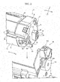
FIG. 2 is a perspective view showing a right side portion of a toner container and a right side portion of an attachment part according to the first embodiment of the present disclosure. -
FIG. 3 is a sectional view schematically showing the toner container according to the first embodiment of the present disclosure. -
FIG. 4 is a sectional view showing a state where a case main body of the toner container is in a first rotating position, in the printer according to the first embodiment of the present disclosure. -
FIG. 5 is a sectional view showing a state where the case main body of the toner container is in a second rotating position, in the printer according to the first embodiment of the present disclosure. -
FIG. 6 is a disassembled perspective view showing a supporter, a transmitter, a moving mechanism and a cover, in the toner container according to the first embodiment of the present disclosure. -
FIG. 7 is a sectional view showing a state where the transmitter is in a first position, in the toner container according to the first embodiment of the present disclosure. -
FIG. 8 is a sectional view showing a state where the transmitter is in a second position, in the toner container according to the first embodiment of the present disclosure. -
FIG. 9 is a perspective view showing a state where a holder is in a first holding position, in the toner container according to the first embodiment of the present disclosure. -
FIG. 10 is a sectional view taken along a line X-X ofFIG. 9 . -
FIG. 11 is a perspective view showing a state where the holder is in a second holding position, in the toner container according to the first embodiment of the present disclosure. -
FIG. 12 is a sectional view taken along a line XII-XII ofFIG. 11 . -
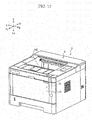
FIG. 13 is a perspective view showing a state where a top cover and a front cover are closed, in the printer according to the first embodiment of the present disclosure. -
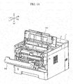
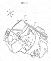
FIG. 14 is a perspective view showing a state where the top cover and the front cover are opened, in the printer according to the first embodiment of the present disclosure. -
FIG. 15 is a perspective view showing the right side portion of the attachment part according to the first embodiment of the present disclosure. -
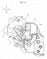
FIG. 16 is a sectional view showing a state where the toner container is inserted to a predetermined position of the attachment part, in the printer according to the first embodiment of the present disclosure. -
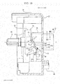
FIG. 17 is a sectional view showing a state where the toner container is attached to the attachment part and the case main body is in the first rotating position, in the printer according to the first embodiment of the present disclosure. -
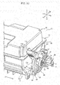
FIG. 18 is a sectional view showing a state where the toner container is attached to the attachment part and the case main body is in the second rotating position, in the printer according to the first embodiment of the present disclosure. -
FIG. 19 is a sectional view showing a state where the holder is in the first holding position, in the toner container according to a second embodiment of the present disclosure. -
FIG. 20 is a sectional view showing a state where the holder is in the second holding position, in the toner container according to the second embodiment of the present disclosure. -
FIG. 21 is a sectional view showing a state where the case main body of the toner container is in the first rotating position, in the printer according to the second embodiment of the present disclosure. -
FIG. 22 is a sectional view showing a state where the case main body of the toner container is in the second rotating position, in the printer according to the second embodiment of the present disclosure. -
FIG. 23 is a perspective view showing a state where a manipulation member is in a first manipulating position, in the toner container according to a third embodiment of the present disclosure. -
FIG. 24 is a perspective view showing a state where the manipulation member is in a second manipulating position, in the toner container according to the third embodiment of the present disclosure. -
FIG. 25 is a perspective view showing a state where the holder is in the first holding position, in the toner container according to a fourth embodiment of the present disclosure. -
FIG. 26 is a perspective view showing a state where the holder is in the second holding position, in the toner container according to the fourth embodiment of the present disclosure. - <A first embodiment> Hereinafter, a first embodiment of the present disclosure will be described with reference to
FIG. 1 to FIG. 18 . - Firstly, an entire structure of a printer 1 (an example of an image forming apparatus) will be described. In the following description, for convenience of explanation, a left side on
FIG. 1 is defined to be a front side of the printer 1. Arrows Fr, Rr, L, R, U and Lo shown in each figure respectively indicate a front side, a rear side, a left side, a right side, an upper side and a lower side of the printer 1. - With reference to
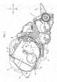
FIG. 1 , the printer 1 includes a box-shaped printer main body 2 (an example of an apparatus main body) . In a lower portion of the printermain body 2, asheet feeding cassette 3 storing a sheet S (an example of a recording medium) is stored. On an upper face of the printermain body 2, an ejected sheet tray 4 is provided. In an upper portion of the printermain body 2, anexposing device 5 is stored below the ejected sheet tray 4. - Inside the printer
main body 2, a conveying path P for the sheet S is provided. At an upstream end of the conveying path P, a sheet feeding part 6 is provided. At a middle portion of the conveying path P, animage forming part 7 is provided. Theimage forming part 7 includes aphotosensitive drum 8 and a developingdevice 10. At a downstream portion of the conveying path P, a fixing device 12 is provided. - In a front upper portion of the printer
main body 2, a toner container 15 (an example of a toner case) is stored. Thetoner container 15 is detachably attached to anattachment part 16. - Next, an operation of the printer 1 having the above described configuration will be described.
- Firstly, laser light (refer to a two-dotted line in
FIG. 1 ) emitted from theexposing device 5 exposes thephotosensitive drum 8 to form an electrostatic latent image on thephotosensitive drum 8. Next, the electrostatic latent image on thephotosensitive drum 8 is developed by the developingdevice 10 to a toner image. Thereby, an image forming operation is finished. - On the other hand, the sheet S fed from the
sheet feeding cassette 3 by the sheet feeding part 6 is conveyed to theimage forming part 7 synchronously with the above described image forming operation. At theimage forming part 7, the above toner image is transferred on the sheet S from thephotosensitive drum 8. The sheet S on which the toner image is transferred is conveyed to the downstream side along the conveying path P and enters the fixing device 12. The fixing device 12 fixes the toner image on the sheet S. The sheet S on which the toner image is fixed is ejected on the ejected sheet tray 4 from a downstream end of the conveying path P. - Next, the
toner container 15 will be described in detail. - An arrow O shown in each figure after
FIG. 2 indicates an outside in the left-and-right direction of thetoner container 15, and an arrow I shown in each figure afterFIG. 2 indicates an inside in the left-and-right direction of thetoner container 15. - With reference to
FIG. 2 andFIG. 3 , thetoner container 15 includes a casemain body 21, an agitator 22 (an example of a rotator) stored in a center portion of the casemain body 21, a conveyer 23 (an example of a rotator) stored in a rear lower portion of the casemain body 21, asupporter 24 arranged at a right end side of the casemain body 21, atransmitter 25 and a movingmechanism 26 which are arranged at a right side (the outside in the left-and-right direction) of thesupporter 24, acover 27 covering a right side (the outside in the left-and-right direction) of the casemain body 21, ashutter 28 arranged at a rear lower side of a right side portion of the casemain body 21 and aconnector 29 arranged at a rear lower side of thesupporter 24. - With reference to
FIG. 4 andFIG. 5 , the casemain body 21 of thetoner container 15 is rotatable between a first rotating position (refer toFIG. 4 ) and a second rotating position (refer toFIG. 5 ), in a state where thetoner container 15 is attached to the attachment part 16 (described later in detail) . In the following description regarding the casemain body 21, words showing directions, such as upper, lower, left, right, front and rear, are used on the basis of a state where the casemain body 21 is in the second rotating position. An arrow RD1 suitably shown in each figure indicates a rotating direction of the casemain body 21 from the first rotating position to the second rotating position (hereinafter, called as "a rotating direction RD1"). - With reference to
FIG. 2 andFIG. 3 , the casemain body 21 has a shape elongated in the left-and-right direction. The casemain body 21 stores a toner (a developer) . The casemain body 21 includes astorage 31 and alid 32 provided at an upper side of thestorage 31. - The
storage 31 of the casemain body 21 is formed in a box-like shape whose upper side is opened. In a right rear portion of a bottom wall 31Lo of thestorage 31, adischarge port 33 through which the toner is discharged is provided. On a center portion of aleft side wall 31L of thestorage 31, an engagingpart 34 protruding to the left side (the outside in the left-and-right direction) is provided. In a center portion of aright side wall 31R of thestorage 31, a supportinghole 35 is provided. Around an upper end of an outer circumference of thestorage 31, a lowerside flange portion 36 is provided. - The
lid 32 of the casemain body 21 is formed in a box-like shape whose lower side is opened. Around a lower end of an outer circumference of thelid 32, an upperside flange portion 37 is provided. The upperside flange portion 37 is fixed to the lowerside flange portion 36 of thestorage 31. Thereby, thelid 32 is integrated with thestorage 31. An inner space of thelid 32 is communicated with an inner space of thestorage 31. - With reference to
FIG. 3 , theagitator 22 of thetoner container 15 is stored in thestorage 31 of the casemain body 21. Theagitator 22 is rotatable around a first rotation axis X extending along the left-and-right direction. That is, the left-and-right direction is a rotation axis direction of theagitator 22 in the present embodiment. Theagitator 22 includes an agitatingshaft 40 extending along the left-and-right direction and an agitatingblade 41 mounted to the agitatingshaft 40. The agitatingblade 41 is made of resin film, for example, and formed in a sheet-like shape. - The
conveyer 23 of thetoner container 15 is stored in thestorage 31 of the casemain body 21. Theconveyer 23 is rotatable around a second rotation axis Y extending along the left-and-right direction. That is, the left-and-right direction is a rotation axis direction of theconveyer 23 in the present embodiment. Theconveyer 23 includes a conveyingshaft 43 extending along the left-and-right direction and aspiral conveying fin 44 protruding on an outer circumference of the conveyingshaft 43. - With reference to
FIG. 6 , thesupporter 24 of thetoner container 15 includes an annularexposed piece 47, acoupling piece 48 protruding from a center portion of the exposedpiece 47 to the left side (the inside in the left-and-right direction), aboss piece 49 protruding from the center portion of the exposedpiece 47 to the right side (the outside in the left-and-right direction) and a pair of insertedpieces 50 protruding from the exposedpiece 47 at an outer circumference of theboss piece 49 to the right side (the outside in the left-and-right direction). - With reference to
FIG. 3 , the exposedpiece 47 of thesupporter 24 is arranged at the right side (the outside in the left-and-right direction) of thestorage 31 of the casemain body 21, and exposed to an outside of the casemain body 21. Around an outer circumferential face of the exposedpiece 47, adriving gear 52 is provided. - The
coupling piece 48 of thesupporter 24 penetrates through the supportinghole 35 provided in theright side wall 31R of thestorage 31 of the casemain body 21. Thereby, thesupporter 24 is rotatably supported by the casemain body 21. A tip end portion of thecoupling piece 48 is inserted into an inside of thestorage 31, and fixed to a right end portion of the agitatingshaft 40 of theagitator 22. Thereby, thesupporter 24 is connected to theagitator 22, and rotatable together with theagitator 22 around the first rotation axis X. - With reference to
FIG. 6 , at a right end portion (an end portion at the outside in the left-and-right direction) of each insertedpiece 50 of thesupporter 24, ahook 54 is provided. Thehook 54 is protruded to an outside in a radial direction (a direction separated from the first rotation axis X). - With reference to
FIG. 7 andFIG. 8 , thetransmitter 25 of thetoner container 15 is arranged at the right side (the outside in the left-and-right direction) of thestorage 31 of the casemain body 21 and outside the casemain body 21. Thetransmitter 25 moves linearly along the left-and-right direction between a first position (refer toFIG. 7 ) and a second position (refer toFIG. 8 ) which is arranged at the right side (the outside in the left-and-right direction) of the first position. - With reference to
FIG. 6 , thetransmitter 25 includes a transmittingpiece 56, acylindrical piece 57 protruding from a center portion of the transmittingpiece 56 to the left side (the inside in the left-and-right direction), a pair of protrudingpieces 58 protruding from the transmittingpiece 56 at an outer circumference of thecylindrical piece 57 to the left side (the inside in the left-and-right direction) and an approximateannular fixing piece 59 fixed to outer circumferential faces of left side portions of the pair of protrudingpieces 58. On a right face (a face at the outside in the left-and-right direction) of the transmittingpiece 56, a transmittingcoupling 61 is provided. Into thecylindrical piece 57, theboss piece 49 of thesupporter 24 is inserted. A pair of insertinggrooves 62 is formed between the pair of protrudingpieces 58. Into each insertinggroove 62, each insertedpiece 50 of thesupporter 24 is inserted. According to the configuration described above, thetransmitter 25 is supported by thesupporter 24 in a state where thetransmitter 25 is movable along the left-and-right direction and is not rotatable with respect to thesupporter 24. The fixingpiece 59 engagingly locks thehook 54 of each insertedpiece 50. Thereby, each insertedpiece 50 is inhibited from being removed from each insertinggroove 62. - With reference to
FIG. 6 , the movingmechanism 26 of thetoner container 15 includes aholder 64 and a coil spring 65 (an example of a biasing member). - With reference to
FIG. 9 to FIG. 12 , theholder 64 of the movingmechanism 26 is rotatable between a first holding position (refer toFIG. 9 andFIG. 10 ) where theholder 64 holds thetransmitter 25 in the first position and a second holding position (refer toFIG. 11 andFIG. 12 ) where theholder 64 holds thetransmitter 25 in the second position, in a state where thetoner container 15 is detached from theattachment part 16. An arrow RD2 suitably shown in each figure indicates a rotating direction of theholder 64 from the first holding position to the second holding position (hereinafter, called as "a rotating direction RD2"). Theholder 64 moves along the left-and-right direction between the above first holding position and the above second holding position, in the state where thetoner container 15 is attached to theattachment part 16. - With reference to
FIG. 6 , theholder 64 includes abase part 67, anarm part 68 extending linearly from an outer circumferential face of thebase part 67 to an outside in a radial direction (a direction separated from the first rotation axis X) and aboss part 69 extending linearly from an outer end portion of thearm part 68 in the radial direction to the right side (the outside in the left-and-right direction). - The
base part 67 of theholder 64 is formed in a cylindrical shape with the first rotation axis X as an axis center. Into an inner circumference of thebase part 67, the pair of protrudingpieces 58 of thetransmitter 25 is rotatably inserted. Thereby, thebase part 67 rotatably holds thetransmitter 25. A left edge portion (an edge portion at the inside in the left-and-right direction) of thebase part 67 comes into contact with the fixingpiece 59 of thetransmitter 25. - On the outer circumferential face of the
base part 67 of theholder 64, a pair of guided parts 71 (only one of them, the one at a near side on the figure, is shown inFIG. 6 ) is protruded. Each guidedpart 71 includes aninclined piece 72 and anon-inclined piece 73 provided at a downstream side of theinclined piece 72 in the rotating direction RD2, and is formed in an approximate V-shape. Theinclined piece 72 is inclined to the right side (the outside in the left-and-right direction) from an upstream side to the downstream side in the rotating direction RD2. Thenon-inclined piece 73 is provided along the rotating direction RD2. - With reference to
FIG. 7 andFIG. 8 , thecoil spring 65 of the movingmechanism 26 is interposed between thesupporter 24 and thetransmitter 25. Thecoil spring 65 is attached to an outer circumference of thecylindrical piece 57 of thetransmitter 25. Thecoil spring 65 presses thetransmitter 25 to the right side (the outside in the left-and-right direction) to bias thetransmitter 25 to the second position (refer toFIG. 8 ) and to bias theholder 64 to the second holding position (refer toFIG. 11 andFIG. 12 ). - With reference to
FIG. 7 andFIG. 8 , thecover 27 of thetoner container 15 includes a plate-shapedmain wall 75, aguide wall 76 and an engagingwall 77 which are arranged at a center side of themain wall 75 and acircumferential wall 78 arranged at an outer circumference side of themain wall 75. - The
main wall 75 of thecover 27 is provided along a plane crossing the first rotation axis X. In a center portion of themain wall 75, a circular throughhole 79 is provided. With reference toFIG. 2 , in lower portions of themain wall 75 and thecircumferential wall 78, anotch 80 is provided. Through thenotch 80, theboss part 69 of theholder 64 is penetrated. Thereby, a tip end portion of theboss part 69 is exposed to the right side (the outside in the left-and-right direction) of thecover 27. - With reference to
FIG. 10 andFIG. 12 , theguide wall 76 of thecover 27 is formed in a cylindrical shape. Theguide wall 76 is protruded from themain wall 75 at an outer circumference of the throughhole 79 to the left side (the inside in the left-and-right direction) . Into theguide wall 76, thebase part 67 of theholder 64 is inserted. Thereby, thecover 27 rotatably supports theholder 64. - On a left edge portion (an edge portion at the inside in the left-and-right direction) of the
guide wall 76 of thecover 27, a pair of guide parts 82 (only one of them, the one at the near side on the figure, is shown inFIG. 10 andFIG. 12 ) is provided. Eachguide part 82 includes an upstream side inclinedpart 83, a downstream side inclinedpart 84 provided at the downstream side of the upstream side inclinedpart 83 in the rotating direction RD2 and anon-inclined part 85 provided at the downstream side of the downstream side inclinedpart 84 in the rotating direction RD2. The upstream side inclinedpart 83 and the downstream side inclinedpart 84 are inclined to the right side (the outside in the left-and-right direction) from the upstream side to the downstream side in the rotating direction RD2. An inclined degree of the upstream side inclinedpart 83 to the rotating direction RD2 is smaller than an inclined degree of theinclined piece 72 of each guidedpart 71 provided in thebase part 67 of theholder 64 to the rotating direction RD2. An inclined degree of the downstream side inclinedpart 84 to the rotating direction RD2 is the same as the inclined degree of theinclined piece 72 to the rotating direction RD2. Thenon-inclined part 85 is provided along the rotating direction RD2. - With reference to
FIG. 9 andFIG. 11 , the engagingwall 77 of thecover 27 is protruded from themain wall 75 at the outer circumference of the throughhole 79 to the right side (the outside in the left-and-right direction). The engagingwall 77 includes a square cylindrical shaped outercylindrical part 88 and a cylindrical shaped innercylindrical part 89 provided on an inner circumference of the outercylindrical part 88. - With reference to
FIG. 4 andFIG. 5 , theshutter 28 of thetoner container 15 is curved in an arc-shape along an outer face of thestorage 31 of the casemain body 21. Theshutter 28 is capable of opening and closing thedischarge port 33 of thestorage 31. - With reference to
FIG. 3 , theconnector 29 of thetoner container 15 includes a connectingshaft 91 and a connectinggear 92 provided around an outer circumference of the connectingshaft 91. The connectingshaft 91 is penetrated through theright side wall 31R of thestorage 31 of the casemain body 21, and fixed to a right end portion of the conveyingshaft 43 of theconveyer 23. The connectinggear 92 is arranged at the right side (the outside in the left-and-right direction) of thestorage 31 of the casemain body 21, and exposed to the outside of the casemain body 21. The connectinggear 92 is connected to thedriving gear 52 of the exposedpiece 47 of thesupporter 24 via anidle gear 93. According to the configuration described above, thesupporter 24 is connected to theconveyer 23 via theidle gear 93 and theconnector 29. - Next, the
attachment part 16 will be described in detail. - With reference to
FIG. 13 andFIG. 14 , an upper side of theattachment part 16 is covered with an openable and closabletop cover 100, and a front side of theattachment part 16 is covered with an openable and closablefront cover 101. By opening thetop cover 100 and thefront cover 101, it becomes possible to attach and detach thetoner container 15 to and from theattachment part 16. With reference toFIG. 14 , to theattachment part 16, thetoner container 15 is detachably attached along an attachment direction Z from the upper side to the lower side. - With reference to
FIG. 15 , theattachment part 16 includes a pair of left and right frames 103 (only theright frame 103 is shown inFIG. 15 ) and a drivingcoupling 104 arranged in an approximate center portion of theright frame 103. - In an inner face of each
frame 103 of theattachment part 16, anattachment groove 110 is provided. Theattachment groove 110 has afirst groove part 111, asecond groove part 112 provided at a downstream side of thefirst groove part 111 in the attachment direction Z and athird groove part 113 provided at the downstream side of thesecond groove part 112 in the attachment direction Z. Thefirst groove part 111 narrows toward the downstream side in the attachment direction Z. Thesecond groove part 112 has a width narrower than thefirst groove part 111 and thethird groove part 113. - In the inner face of the
right frame 103, acommunication hole 114 is provided at a position corresponding to thethird groove part 113. In the inner face of theright frame 103, aninsertion groove 115 is provided. On a face at the downstream side of theinsertion groove 115 in the attachment direction Z, arestriction part 116 is provided. - With reference to
FIG. 7 andFIG. 8 , the drivingcoupling 104 of theattachment part 16 is exposed through thecommunication hole 114 of theright frame 103. The drivingcoupling 104 is rotatably supported by a holdingmember 118. The drivingcoupling 104 is connected to a drivingsource 119 constituted by a motor and the others. - Next, an operation to discharge the toner from the
toner container 15 will be described. - With reference to
FIG. 3 , when the toner is discharged from thetoner container 15, in a state where the transmittingcoupling 61 of thetransmitter 25 is coupled to the drivingcoupling 104 and thedischarge port 33 of thestorage 31 is opened, the drivingsource 119 is driven. When the drivingsource 119 is driven, the drivingcoupling 104 is rotated by rotation driving force from the drivingsource 119. When the drivingcoupling 104 is thus rotated, rotation of the drivingcoupling 104 is transmitted to theagitator 22 by thetransmitter 25 and thesupporter 24, and theagitator 22 is rotated. As a result, the toner stored in thestorage 31 is agitated by theagitator 22. - When the driving
coupling 104 is rotated as described above, the rotation is transmitted to theconveyer 23 by thetransmitter 25, thesupporter 24, theidle gear 93 and theconnector 29, and theconveyer 23 is rotated. As a result, as shown in an arrow A inFIG. 3 , the toner stored in thestorage 31 is conveyed toward thedischarge port 33 of thestorage 31 by theconveyer 23. The toner thus conveyed toward thedischarge port 33 of thestorage 31 is discharged through thedischarge port 33 of thestorage 31 to the outside of thetoner container 15. The toner discharged to the outside of thetoner container 15 is replenished to the developing device 10 (refer toFIG. 1 ). - Next, a work to check operation of the
transmitter 25 by a worker, such as a user and a serviceman, will be described. - In the state where the
toner container 15 is detached from theattachment part 16, theholder 64 is in the second holding position (refer toFIG. 11 andFIG. 12 ), and theinclined piece 72 and thenon-inclined piece 73 of the guidedpart 71 of theholder 64 respectively come into contact with the downstream side inclinedpart 84 and thenon-inclined part 85 of theguide part 82 of thecover 27. Thetransmitter 25 is held in the second position (refer toFIG. 8 ) by theholder 64, and the transmittingcoupling 61 of thetransmitter 25 protrudes to the right side (the outside in the left-and-right direction) further than the engagingwall 77 of thecover 27. - From this state, the worker presses the
boss part 69 of theholder 64 to the upper side. Consequently, theholder 64 rotates with respect to the casemain body 21 from the second holding position (refer toFIG. 11 andFIG. 12 ) to the first holding position (refer toFIG. 9 andFIG. 10 ) against biasing force of thecoil spring 65. Consequently, theinclined piece 72 of the guidedpart 71 of theholder 64 moves along the downstream side inclinedpart 84 of theguide part 82 of thecover 27, and a boundary portion between theinclined piece 72 and thenon-inclined piece 73 of the guidedpart 71 comes into contact with the upstream side inclinedpart 83 of theguide part 82. Consequently, theholder 64 moves to the left side (the inside in the left-and-right direction), and thetransmitter 25 held by theholder 64 moves from the second position (refer toFIG. 8 ) to the first position (refer toFIG. 7 ). As a result, the transmittingcoupling 61 of thetransmitter 25 is retracted to an inside of the engagingwall 77 of thecover 27. In this state, an entire portion of thetransmitter 25 is retracted to the inside of thecover 27. - Next, the worker releases the pressing of the
boss part 69 of theholder 64. Consequently, theholder 64 rotates with respect to the casemain body 21 from the first holding position (refer toFIG. 9 andFIG. 10 ) to the second holding position (refer toFIG. 11 andFIG. 12 ) by the biasing force of thecoil spring 65. Consequently, theinclined piece 72 of the guidedpart 71 of theholder 64 moves along the downstream side inclinedpart 84 of theguide part 82 of thecover 27, and theinclined piece 72 and thenon-inclined piece 73 of the guidedpart 71 respectively come into contact with the downstream side inclinedpart 84 and thenon-inclined part 85 of theguide part 82. Consequently, theholder 64 moves to the right side (the outside in the left-and-right direction), and thetransmitter 25 held by theholder 64 moves from the first position (refer toFIG. 7 ) to the second position (refer toFIG. 8 ). As a result, the transmittingcoupling 61 of thetransmitter 25 protrudes to the right side (the outside in the left-and-right direction) further than the engagingwall 77 of thecover 27. - As described above, in the present embodiment, as the
holder 64 rotates with respect to the casemain body 21, thetransmitter 25 moves between the first position and the second position. By applying such a configuration, it becomes possible to move thetransmitter 25 in the left-and-right direction by a simple operation. Accordingly, the worker is allowed to easily check whether thetransmitter 25 is normally operated. - Next, an operation to set the
toner container 15 to theattachment part 16 by a worker, such as a user and a serviceman, will be described. - In the state where the
toner container 15 is detached from theattachment part 16, theholder 64 is in the second holding position (refer toFIG. 11 andFIG. 12 ), and theinclined piece 72 and thenon-inclined piece 73 of the guidedpart 71 of theholder 64 respectively come into contact with the downstream side inclinedpart 84 and thenon-inclined part 85 of theguide part 82 of thecover 27. Thetransmitter 25 is held in the second position (refer toFIG. 8 ) by theholder 64, and the transmittingcoupling 61 of thetransmitter 25 protrudes to the right side (the outside in the left-and-right direction) further than the engagingwall 77 of thecover 27. Theshutter 28 closes thedischarge port 33 of thestorage 31. - When the worker sets the
toner container 15 to theattachment part 16, as shown inFIG. 2 , the worker inserts thetoner container 15 to theattachment part 16 along the attachment direction Z. As shown inFIG. 16 , when thetoner container 15 is inserted to a predetermined position in theattachment part 16, therestriction part 116 provided in theinsertion groove 115 comes into contact with theboss part 69 of theholder 64. This restricts rotation of theholder 64. - From this state, when the worker further inserts the
toner container 15 to theattachment part 16 along the attachment direction Z, as shown inFIG. 17 , thetoner container 15 is attached to theattachment part 16. Consequently, therestriction part 116 provided in theinsertion groove 115 of theattachment part 16 presses theboss part 69 of theholder 64, and theholder 64 moves from the second holding position (refer toFIG. 11 andFIG. 12 ) to the first holding position (refer toFIG. 9 andFIG. 10 ) against the biasing force of thecoil spring 65. Consequently, theinclined piece 72 of the guidedpart 71 of theholder 64 moves along the downstream side inclinedpart 84 of theguide part 82 of thecover 27, and the boundary portion between theinclined piece 72 and thenon-inclined piece 73 of the guidedpart 71 comes into contact with the upstream side inclinedpart 83 of theguide part 82. Consequently, theholder 64 moves to the left side (the inside in the left-and-right direction), and thetransmitter 25 held by theholder 64 moves from the second position (refer toFIG. 8 ) to the first position (refer toFIG. 7 ). As a result, the transmittingcoupling 61 of thetransmitter 25 is retracted to the inside of the engagingwall 77 of thecover 27 and faces the drivingcoupling 104. - Additionally, as the
toner container 15 is attached to theattachment part 16 as described above, as shown inFIG. 17 , the engagingwall 77 of thecover 27 passes through thefirst groove part 111 and thesecond groove part 112, and is engaged with thethird groove part 113 of theattachment groove 110 of theright frame 103. Meanwhile, the engagingpart 34 of the casemain body 21 passes through thefirst groove part 111 and thesecond groove part 112, and is engaged with thethird groove part 113 of theattachment groove 110 of the left frame 103 (not shown in figures). - Next, in the state where the
restriction part 116 comes into contact with theboss part 69 of theholder 64 and the rotation of theholder 64 is restricted, the worker rotates the casemain body 21 with respect to theholder 64 from the first rotating position (refer toFIG. 4 ) to the second rotating position (refer toFIG. 5 ) along the rotating direction RD1. As a result, theshutter 28 opens thedischarge port 33 of thestorage 31. - Additionally, as the case
main body 21 is rotated from the first rotating position to the second rotating position as described above, thecover 27 rotates integrally with the casemain body 21. Consequently, as shown inFIG. 18 , the pressing of theholder 64 to the first holding position (refer toFIG. 9 andFIG. 10 ) by therestriction part 116 is released, and theholder 64 moves from the first holding position (refer toFIG. 9 andFIG. 10 ) to the second holding position (refer toFIG. 11 andFIG. 12 ) by the biasing force of thecoil spring 65. Consequently, theinclined piece 72 of the guidedpart 71 of theholder 64 moves along the downstream side inclinedpart 84 of theguide part 82 of thecover 27, and theinclined piece 72 and thenon-inclined piece 73 of the guidedpart 71 respectively come into contact with the downstream side inclinedpart 84 and thenon-inclined part 85 of theguide part 82. Consequently, theholder 64 moves to the right side (the outside in the left-and-right direction), and thetransmitter 25 held by theholder 64 moves from the first position (refer toFIG. 7 ) to the second position (refer toFIG. 8 ). As a result, the transmittingcoupling 61 of thetransmitter 25 protrudes to the right side (the outside in the left-and-right direction) further than the engagingwall 77 of thecover 27, and is coupled to the drivingcoupling 104. - Additionally, as the case
main body 21 is rotated from the first rotating position to the second rotating position as described above, as shown inFIG. 17 andFIG. 18 , the engagingwall 77 of thecover 27 rotates in thethird groove part 113 of theattachment groove 110 of theright frame 103. Meanwhile, the engagingpart 34 of the casemain body 21 rotates in thethird groove part 113 of theattachment groove 110 of the left frame 103 (not shown in figures). Thereby, the engagingwall 77 and theengaging part 34 are restricted from being removed from theattachment grooves 110 of theframes 103, and thetoner container 15 is restricted from being detached from theattachment part 16. By the above operation, the setting of thetoner container 15 to theattachment part 16 is completed. - When the
toner container 15 is detached from theattachment part 16, the worker rotates the casemain body 21 from the second rotating position (refer toFIG. 5 ) to the first rotating position (refer toFIG. 4 ) and then pulls out thetoner container 15 from theattachment part 16 along a direction opposite to the attachment direction Z. - In the present embodiment, as described above, the
toner container 15 includes the movingmechanism 26 which moves thetransmitter 25 between the first position and the second position which is arranged at the right side (the outside in the left-and-right direction) of the first position. By the movingmechanism 26, as the casemain body 21 is rotated from the first rotating position to the second rotating position, thetransmitter 25 is moved from the first position to the second position. By applying such a configuration, it becomes possible to move thetransmitter 25 to the right side by a simple operation and to reduce a worker's load for the attachment and detachment work of thetoner container 15. - The moving
mechanism 26 includes theholder 64 which rotates between the first holding position where theholder 64 holds thetransmitter 25 in the first position and the second holding position where theholder 64 holds thetransmitter 25 in the second position. By applying such a configuration, it becomes possible to make the movingmechanism 26 to be a simple structure. - The
base part 67 of theholder 64 is inserted in theguide wall 76 of thecover 27. By applying such a configuration, it becomes possible to rotatably support theholder 64 by thecover 27 by using a simple structure. - The upstream side inclined
part 83 and the downstream side inclinedpart 84 of theguide part 82 of thecover 27 are inclined to the right side (the outside in the left-and-right direction) from the upstream side to the downstream side in the rotating direction RD2, and theholder 64 includes the guidedpart 71 coming into contact with the upstream side inclinedpart 83 and the downstream side inclinedpart 84. By applying such a configuration, it becomes possible to move theholder 64 in the left-and-right direction surely as thecover 27 is rotated. - The
transmitter 25 is supported by thesupporter 24 in the state where thetransmitter 25 is movable along the left-and-right direction and is not rotatable with respect to thesupporter 24, and thecoil spring 65 is interposed between thesupporter 24 and thetransmitter 25. By applying such a configuration, it becomes possible to integrate thesupporter 24, thetransmitter 25 and thecoil spring 65 and to arrange them in a narrow space. - The printer 1 includes the
toner container 15 and theattachment part 16 to which thetoner container 15 is detachably attached. By applying such a configuration, it becomes possible to replace thetoner container 15 easily. - By the way, in some cases, with an opening and closing operation of the
top cover 100 provided in the printermain body 2 or the attachment operation of thetoner container 15 to theattachment part 16, the drivingcoupling 104 is moved to be coupled to the transmittingcoupling 61. However, to achieve such a configuration, theattachment part 16 requires a driving mechanism to move the drivingcoupling 104, and therefore, theattachment part 16 may be complicated in its structure. - However, in the present embodiment, as the case
main body 21 is rotated from the first rotating position to the second rotating position in the state where thetoner container 15 is attached to theattachment part 16, the movingmechanism 26 moves thetransmitter 25 from the first position to the second position, and the transmittingcoupling 61 is coupled to the drivingcoupling 104. By applying such a configuration, theattachment part 16 does not require the driving mechanism to move the drivingcoupling 104 so that it becomes possible to suppress the complication of the structure of theattachment part 16 and to achieve space saving of the printermain body 2. - Additionally, as the
toner container 15 is attached to theattachment part 16, therestriction part 116 provided in theattachment part 16 presses theholder 64, and theholder 64 moves from the second holding position to the first holding position against the biasing force of thecoil spring 65. In the state where thetoner container 15 is attached to theattachment part 16, as the casemain body 21 is rotated from the first rotating position to the second rotating position, the pressing of theholder 64 to the first holding position by therestriction part 116 is released, and theholder 64 moves from the first holding position to the second holding position by the biasing force of thecoil spring 65. By applying such a configuration, it becomes possible to move theholder 64 between the first holding position and the second holding position by using a simple structure. - In the present embodiment, entire parts of the
agitator 22 and theconveyer 23 are stored in the casemain body 21. On the other hand, in another embodiment, parts of theagitator 22 and/or theconveyer 23 may be stored in the casemain body 21. - In the present embodiment, an entire part of the
transmitter 25 is arranged outside the casemain body 21. On the other hand, in another embodiment, a part of thetransmitter 25 may be arranged outside the casemain body 21. - In the present embodiment, the configuration of the present disclosure is applied to the printer 1. On the other hand, in another embodiment, the configuration of the present disclosure may be applied to an image forming apparatus, such as a copying machine, a facsimile and a multifunctional peripheral, other than the printer 1.
- <A second embodiment> Hereinafter, a second embodiment of the present disclosure will be described with reference to
FIG. 19 to FIG. 22 . - Firstly, the
toner container 151 according to the second embodiment will be described. The same configurations as thetoner container 15 according to the first embodiment are not explained. - With reference to
FIG. 19 andFIG. 20 , the movingmechanism 153 of thetoner container 151 includes alocking mechanism 154, in addition to theholder 64 and thecoil spring 65. Thelocking mechanism 154 includes a pair of first projections 155 (only one of them, the one at the near side on the figure, is shown inFIG. 19 andFIG. 20 ) and a pair of second projections 156 (only one of them, the one at the near side on the figure, is shown inFIG. 19 andFIG. 20 ). Eachfirst projection 155 is protruded from each guidedpart 71 of theholder 64 to the right side (the outside in the left-and-right direction). Each second projection 156 is protruded from each guidepart 82 of thecover 27 to the left side (the inside in the left-and-right direction). - Next, the
attachment part 152 according to the second embodiment will be described. The same configurations as theattachment part 16 according to the first embodiment are not explained. - With reference to
FIG. 21 andFIG. 22 , in the inner face of theright frame 103 of theattachment part 152, theinsertion groove 115 is provided. On the face at the downstream side in the attachment direction Z of theinsertion groove 115, therestriction part 161 is provided. In theinsertion groove 115, apressing rib 162 extending along the attachment direction Z is provided adjacent to therestriction part 161. Thepressing rib 162 includes apressing face 163 at a rear upper side (the downstream side in the rotating direction RD1) of therestriction part 161. - Next, an operation to set the
toner container 151 to theattachment part 152 by a worker, such as a user and a serviceman, will be described. The same operations as the first embodiment are not explained. - In the state where the
toner container 151 is detached from theattachment part 152, eachfirst projection 155 and each second projection 156 of thelocking mechanism 154 are engaged with each other, and theholder 64 is held in the first holding position (refer toFIG. 19 ) against the biasing force of thecoil spring 65. That is, theholder 64 is held in the first holding position by thelocking mechanism 154. Thereby, the transmittingcoupling 61 of thetransmitter 25 is retracted to the inside of the engagingwall 77 of thecover 27. - When the worker sets the
toner container 151 to theattachment part 152, the worker attaches thetoner container 151 to theattachment part 152 along the attachment direction Z. Consequently, as shown inFIG. 21 , theboss part 69 of theholder 64 comes into contact with therestriction part 161 and thepressing face 163 of theinsertion groove 115 of theattachment part 152. - Next, the worker rotates the case
main body 21 from the first rotating position to the second rotating position. Consequently, as shown inFIG. 22 , thepressing face 163 of theinsertion groove 115 presses theboss part 69. The pressing releases the engagement of eachfirst projection 155 and each second projection 156 of thelocking mechanism 154. That is, the holding of theholder 64 in the first holding position by thelocking mechanism 154 is released. Consequently, theholder 64 rotates from the first holding position (refer toFIG. 19 ) to the second holding position (refer toFIG. 20 ) by the biasing force of thecoil spring 65. Consequently, theholder 64 moves to the right side (the outside in the left-and-right direction), and thetransmitter 25 held by theholder 64 moves from the first position to the second position. As a result, the transmittingcoupling 61 of thetransmitter 25 protrudes to the right side (the outside in the left-and-right direction) further than the engagingwall 77 of thecover 27 and is coupled to the drivingcoupling 104. - In the present embodiment, as described above, the
toner container 151 includes thecoil spring 65 biasing theholder 64 to the second holding position and thelocking mechanism 154 holding theholder 64 to the first holding position against the biasing force of thecoil spring 65. Therefore, in the state where thetoner container 151 is detached from theattachment part 152, it becomes possible to hold thetransmitter 25 in the first position by theholder 64 and to retract the transmittingcoupling 61 of thetransmitter 25 to the inside of the engagingwall 77 of thecover 27. Accordingly, it becomes possible to suppress the transmittingcoupling 61 from being damaged by impact applied from the outside at transporting of thetoner container 151. - Additionally, the
locking mechanism 154 includes thefirst projection 155 provided in theholder 64 and the second projection 156 which is provided in thecover 27 and engaged with thefirst projection 155. By applying such a configuration, it becomes possible to constitute thelocking mechanism 154 without adding dedicated members. - Additionally, in the state where the
toner container 151 is attached to theattachment part 152, as the casemain body 21 is rotated from the first rotating position to the second rotating position, thepressing face 163 provided in theattachment part 152 presses theholder 64, the holding of theholder 64 in the first holding position by thelocking mechanism 154 is released, and theholder 64 moves from the first holding position to the second holding position by the biasing force of thecoil spring 65. By applying such a configuration, it becomes possible to move theholder 64 from the first holding position to the second holding position surely. - <A third embodiment> Hereinafter, a third embodiment of the present disclosure will be described with reference to
FIG. 23 andFIG. 24 . - The toner container 171 (an example of a toner case) according to the third embodiment includes a
manipulation member 172, in addition to each component of thetoner container 15 according to the first embodiment. In thetoner container 171, the components other than themanipulation member 172 have the approximate same configurations as thetoner container 15 according to the first embodiment, except that theboss part 69 of theholder 64 extends from an end portion at the outside in the radial direction of thearm part 68 to the left side (the inside in the left-and-right direction) and theshutter 28 is formed in a cylindrical shape, and their detail explanations are omitted. - The
manipulation member 172 of thetoner container 171 is arranged at the right side (the outside in the left-and-right direction) of thestorage 31 of the casemain body 21. That is, themanipulation member 172 is arranged outside the casemain body 21. Themanipulation member 172 is rotatable around the first rotation axis X between a first manipulating position (refer toFIG. 23 ) and a second manipulating position (refer toFIG. 24 ). Themanipulation member 172 is connected to theshutter 28 via a gear mechanism (not shown). - The
manipulation member 172 includes amain body part 173, a manipulatedpart 174 extending linearly from an outer circumferential face of themain body part 173 to an outside in a radial direction (a direction separated from the first rotation axis X) and apressing part 175 extending linearly from the outer circumferential face of themain body part 173 to the outside in the radial direction (the direction separated from the first rotation axis X). Thepressing part 175 is formed in a laterally laid U-shape. Into an inner circumference of thepressing part 175, theboss part 69 of theholder 64 is engaged. - In the
toner container 171 having the above described configuration, in a state where themanipulation member 172 is arranged at the first manipulating position (refer toFIG. 23 ), thepressing part 175 of themanipulation member 172 presses theboss part 69 of theholder 64, and theholder 64 is held in the first holding position. Consequently, thetransmitter 25 is held in the first position by theholder 64, and the transmittingcoupling 61 of thetransmitter 25 is retracted to an inside of the throughhole 79 of the cover 27 (only a part of thecover 27 is shown inFIG. 23 andFIG. 24 ). Theshutter 28 closes thedischarge port 33 of the casemain body 21. - From this state, when a worker, such as a user and a serviceman, presses the manipulated
part 174 of themanipulation member 172 to the rear side, themanipulation member 172 is rotated from the first manipulating position (refer toFIG. 23 ) to the second manipulating position (refer toFIG. 24 ). Consequently, the pressing of theholder 64 to the first holding position by themanipulation member 172 is released, and theholder 64 rotates with respect to the casemain body 21 from the first holding position to the second holding position by the biasing force of thecoil spring 65. Consequently, according to the same process as the first embodiment, theholder 64 moves to the right side (the outside in the left-and-right direction), and thetransmitter 25 held by theholder 64 moves from the first position to the second position. As a result, the transmittingcoupling 61 of thetransmitter 25 protrudes to the right side (the outside in the left-and-right direction) further than the throughhole 79 of thecover 27. Thereby, the transmittingcoupling 61 is enabled to be coupled to the drivingcoupling 104. - When the
manipulation member 172 is rotated from the first manipulating position (refer toFIG. 23 ) to the second manipulating position (refer toFIG. 24 ) as described above, the rotation of themanipulation member 172 is transmitted to theshutter 28, and theshutter 28 rotates. Thereby, theshutter 28 opens thedischarge port 33 of the casemain body 21. - From this state, when the worker presses the manipulated
part 174 of themanipulation member 172 to the front side, themanipulation member 172 is rotated from the second manipulating position (refer toFIG. 24 ) to the first manipulating position (refer toFIG. 23 ). Consequently, thepressing part 175 of themanipulation member 172 presses theboss part 69 of theholder 64, and theholder 64 rotates with respect to the casemain body 21 from the second holding position to the first holding position against the biasing force of thecoil spring 65. Consequently, according to the same process as the first embodiment, theholder 64 moves to the left side (the inside in the left-and-right direction), and thetransmitter 25 held by theholder 64 moves from the second position to the first position. As a result, the transmittingcoupling 61 of thetransmitter 25 is retracted to the inside of the throughhole 79 of thecover 27. Thereby, the coupling of the transmittingcoupling 61 to the drivingcoupling 104 is inhibited. - When the
manipulation member 172 is rotated from the second manipulating position (refer toFIG. 24 ) to the first manipulating position (refer toFIG. 23 ) as described above, the rotation of themanipulation member 172 is transmitted to theshutter 28, and theshutter 28 rotates. As a result, theshutter 28 closes thedischarge port 33 of the casemain body 21. - In the present embodiment, as the
manipulation member 172 is rotated between the first manipulating position and the second manipulating position, theholder 64 rotates between the first holding position and the second holding position. By applying such a configuration, it becomes possible to move thetransmitter 25 along the left-and-right direction by a simple operation. - In the present embodiment, the
manipulation member 172 rotates between the first manipulating position and the second manipulating position. On the other hand, in another embodiment, themanipulation member 172 may move linearly between the first manipulating position and the second manipulating position. - <A fourth embodiment> Hereinafter, a fourth embodiment of the present disclosure will be described with reference to
FIG. 25 andFIG. 26 . - In the toner container 181 (an example of a toner case) according to the fourth embodiment, the components other than the moving
mechanism 182 and theshutter 183 have the approximate same configurations as thetoner container 15 according to the first embodiment, and their detail explanations are omitted. - The moving
mechanism 182 of thetoner container 181 includes theholder 186 and the coil spring 187 (an example of a pressing member). - The
holder 186 of the movingmechanism 182 is movable along the left-and-right direction (the rotation axis directions of theagitator 22 and the conveyer 23) with respect to the casemain body 21 between the first holding position (refer toFIG. 25 ) where theholder 186 holds thetransmitter 25 in the first position and the second holding position (refer toFIG. 26 ) where theholder 186 holds thetransmitter 25 in the second position. - The
holder 186 includes abase part 189 formed in a cylindrical shape with the first rotation axis X as an axis center, anarm part 190 extending linearly from an outer circumferential face of thebase part 189 to an outside in a radial direction (a direction separated from the first rotation axis X), and afirst rack piece 191 extending linearly from an end portion at the outside in the radial direction of thearm part 190 to the left side (the inside in the left-and-right direction) . Thebase part 189 rotatably holds thetransmitter 25. On a lower face of thefirst rack piece 191, afirst rack gear 192 is provided. Thefirst rack gear 192 is meshed with apinion gear 193 from an upper side. - The
coil spring 187 of the movingmechanism 182 is interposed between thesupporter 24 and thetransmitter 25. Thecoil spring 187 presses thetransmitter 25 to the right side (the outside in the left-and-right direction), and thetransmitter 25 is pressed against theholder 186 by thecoil spring 187. - The
shutter 183 of thetoner container 181 includes a shuttermain body 194 and asecond rack piece 195 extending from a right end portion of the shuttermain body 194 to the right side (the outside in the left-and-right direction) . The shuttermain body 194 is arranged along a lower face (an outer face) of thestorage 31 of the casemain body 21. On an upper face of thesecond rack piece 195, asecond rack gear 196 is provided. Thesecond rack gear 196 is meshed with thepinion gear 193 from a lower side. - In the
toner container 181 having the above described configuration, in a state where theholder 186 is arranged in the first holding position (refer toFIG. 25 ), thetransmitter 25 is held in the first position by theholder 186, and the transmittingcoupling 61 of thetransmitter 25 is retracted to the inside of the throughhole 79 of the cover 27 (not shown inFIG. 25 andFIG. 26 ). The shuttermain body 194 of theshutter 183 closes thedischarge port 33 of the casemain body 21. - From this state, when the
shutter 183 is moved to the left side (one side in the left-and-right direction), the shuttermain body 194 of theshutter 183 opens thedischarge port 33 of the casemain body 21. Consequently, theholder 186 connected to theshutter 183 via thepinion gear 193 moves to the right side (the other side in the left-and-right direction) with respect to the casemain body 21 from the first holding position (refer toFIG. 25 ) to the second holding position (refer toFIG. 26 ). Consequently, thetransmitter 25 held by theholder 186 moves from the first position to the second position, and the transmittingcoupling 61 of thetransmitter 25 protrudes to the right side (the outside in the left-and-right direction) further than the throughhole 79 of thecover 27. Thereby, the transmittingcoupling 61 is enabled to be coupled to the drivingcoupling 104. - From this state, when the
shutter 183 is moved to the right side (the other side in the left-and-right direction), the shuttermain body 194 of theshutter 183 closes thedischarge port 33 of the casemain body 21. Consequently, theholder 186 connected to theshutter 183 via thepinion gear 193 moves to the left side (the one side in the left-and-right direction) with respect to the casemain body 21 from the second holding position (refer toFIG. 26 ) to the first holding position (refer toFIG. 25 ). Consequently, thetransmitter 25 held by theholder 186 moves from the second position to the first position, and the transmittingcoupling 61 of thetransmitter 25 is retracted to the inside of the throughhole 79 of thecover 27. Thereby, the coupling of the transmittingcoupling 61 to the drivingcoupling 104 is released. - In the present embodiment, the
holder 186 of the movingmechanism 182 moves along the left-and-right direction from the first holding position (refer toFIG. 25 ) where theholder 186 holds thetransmitter 25 in the first position and the second holding position (refer toFIG. 26 ) where theholder 186 holds thetransmitter 25 in the second position. By applying such a configuration, it becomes possible to move thetransmitter 25 along the left-and-right direction by a simple structure.
Claims (12)
- A toner case (15, 151, 171, 181) comprising:a case main body (21) storing a toner;a rotator (22, 23) stored in the case main body (21) and rotating around a rotation axis (X, Y);a transmitter (25) arranged outside the case main body (21) and transmitting rotation to the rotator (22, 23); anda moving mechanism (26, 153, 182) which moves the transmitter (25) between a first position and a second position which is arranged further away from the first position in a rotation axis direction of the rotator (22, 23), pointing to an outside of the case main body (21),wherein the moving mechanism (26, 153, 182) includes a holder (64, 186) holding the transmitter (25),as the holder (64, 186) moves with respect to the case main body (21), the transmitter (25) moves between the first position and the second position,wherein the transmitter (25) moves, with respect to the case main body (21), linearly along the rotation axis direction between the first position and the second position.
- The toner case (15, 151, 171) according to claim 1,
wherein the holder (64) rotates between a first holding position where the holder (64) holds the transmitter (25) in the first position and a second holding position where the holder (64) holds the transmitter (25) in the second position. - The toner case (151) according to claim 2, wherein the moving mechanism (153) further includes:a biasing member (65) biasing the holder (64) to the second holding position; anda locking mechanism (154) holding the holder (64) in the first holding position against biasing force of the biasing member (65).
- The toner case (151) according to claim 3, further comprising a cover (27) covering an outside of the case main body (21) in the rotation axis direction,
wherein the locking mechanism (154) includes:a first projection (155) provided on one of the holder (64) and the cover (27); anda second projection (156) provided on another of the holder (64) and the cover (27), and engaging with the first projection (155). - The toner case (171) according to claim 2, further comprising a manipulation member (172) arranged outside the case main body (21) and movable between a first manipulating position and a second manipulating position,
wherein as the manipulation member (172) moves between the first manipulating position and the second manipulating position, the holder (64) rotates between the first holding position and the second holding position. - The toner case (15, 151, 171) according to any one of claims 2, 3 and 5 further comprising a cover (27) covering an outside of the case main body (21) in the rotation axis direction,
wherein the cover (27) includes:a main wall (75) having a through hole (79); anda guide wall (76) protruding from the main wall (75) at an outer circumference of the through hole (79) toward an inside in the rotation axis direction,wherein a part of the holder (64) is inserted in the guide wall (76). - The toner case (15, 151, 171) according to claim 6,
wherein a guide part (82) is formed on an edge of the guide wall (76) at an inside in the rotation axis direction,
at least a part of the guide part (82) is inclined to an outside in the rotation axis direction from an upstream side to a downstream side in a rotating direction of the holder (64) from the first holding position to the second holding position, and
the holder (64) includes a guided part (71) which comes into contact with the part of the guide part (82). - The toner case (151) according to claim 3 or 4, further comprising a supporter (24) connected to the rotator (22, 23),
wherein the transmitter (25) is supported by the supporter (24) in a state where the transmitter (25) is movable in the rotation axis direction and is not rotatable with respect to the supporter (24), and
the biasing member (65) is interposed between the supporter (24) and the transmitter (25). - The toner case (181) according to claim 1, wherein the holder (186) moves along the rotation axis direction between a first holding position where the holder (186) holds the transmitter (25) in the first position and a second holding position where the holder (64) holds the transmitter (25) in the second position.
- The toner case (15) according to claim 1, further comprising a cover (27) covering an outside of the case main body (21) in the rotation axis direction,
wherein an entirety of the transmitter (25) is retracted to an inside of the cover (27) in a state where the transmitter (25) is held in the first position, and
a part of the transmitter (25) protrudes to an outside of the cover (27) in the rotation axis direction in a state where the transmitter (25) is held in the second position. - The toner case (15) according to claim 1,
wherein the holder (64) includes a base part (67) formed in a cylindrical shape with the rotation axis (X) as an axis center,
the transmitter (25) is rotatably inserted into an inner circumference of the base part (67). - An image forming apparatus (1) comprising:the toner case (15, 151, 171, 181) according to any one of claims 1-11; andan attachment part (16, 152) to which the toner case (15, 151, 171, 181) is detachably attached.
Applications Claiming Priority (5)
| Application Number | Priority Date | Filing Date | Title |
|---|---|---|---|
| JP2016239512 | 2016-12-09 | ||
| JP2016249284A JP6575502B2 (en) | 2016-12-22 | 2016-12-22 | Toner container and image forming apparatus |
| JP2016249283A JP6638640B2 (en) | 2016-12-22 | 2016-12-22 | Toner container and image forming apparatus |
| JP2017134885A JP6935693B2 (en) | 2016-12-09 | 2017-07-10 | Toner container and image forming device |
| EP17206088.1A EP3333634B1 (en) | 2016-12-09 | 2017-12-08 | Toner case and image forming apparatus |
Related Parent Applications (2)
| Application Number | Title | Priority Date | Filing Date |
|---|---|---|---|
| EP17206088.1A Division-Into EP3333634B1 (en) | 2016-12-09 | 2017-12-08 | Toner case and image forming apparatus |
| EP17206088.1A Division EP3333634B1 (en) | 2016-12-09 | 2017-12-08 | Toner case and image forming apparatus |
Publications (2)
| Publication Number | Publication Date |
|---|---|
| EP3457217A1 true EP3457217A1 (en) | 2019-03-20 |
| EP3457217B1 EP3457217B1 (en) | 2020-09-09 |
Family
ID=60629556
Family Applications (2)
| Application Number | Title | Priority Date | Filing Date |
|---|---|---|---|
| EP18203400.9A Active EP3457217B1 (en) | 2016-12-09 | 2017-12-08 | Toner case and image forming apparatus |
| EP17206088.1A Active EP3333634B1 (en) | 2016-12-09 | 2017-12-08 | Toner case and image forming apparatus |
Family Applications After (1)
| Application Number | Title | Priority Date | Filing Date |
|---|---|---|---|
| EP17206088.1A Active EP3333634B1 (en) | 2016-12-09 | 2017-12-08 | Toner case and image forming apparatus |
Country Status (2)
| Country | Link |
|---|---|
| US (1) | US10073375B2 (en) |
| EP (2) | EP3457217B1 (en) |
Families Citing this family (4)
| Publication number | Priority date | Publication date | Assignee | Title |
|---|---|---|---|---|
| JP6638640B2 (en) * | 2016-12-22 | 2020-01-29 | 京セラドキュメントソリューションズ株式会社 | Toner container and image forming apparatus |
| JP6575502B2 (en) * | 2016-12-22 | 2019-09-18 | 京セラドキュメントソリューションズ株式会社 | Toner container and image forming apparatus |
| JP6927733B2 (en) * | 2017-04-14 | 2021-09-01 | シャープ株式会社 | Image forming device |
| USD952030S1 (en) * | 2019-10-23 | 2022-05-17 | Lexmark International, Inc. | Toner cartridge |
Citations (4)
| Publication number | Priority date | Publication date | Assignee | Title |
|---|---|---|---|---|
| EP2530532A1 (en) * | 2010-01-28 | 2012-12-05 | Zhuhai Seine Technology Limited | Cartridge |
| US20150160608A1 (en) * | 2013-12-11 | 2015-06-11 | Canon Kabushiki Kaisha | Drive transmission mechanism and image forming apparatus provided with the same |
| US20160154376A1 (en) * | 2013-09-29 | 2016-06-02 | Apex Technology Co., Ltd. | Rotational force driving assembly and process cartridge |
| US20160313674A1 (en) * | 2015-04-27 | 2016-10-27 | Kyocera Document Solutions Inc. | Developer supplier, developing device including the same, image forming apparatus, and developer container included in the developer supplier |
Family Cites Families (12)
| Publication number | Priority date | Publication date | Assignee | Title |
|---|---|---|---|---|
| JP2001305841A (en) | 2000-04-25 | 2001-11-02 | Matsushita Electric Ind Co Ltd | Toner cartridge and image forming apparatus equipped with the same |
| JP4414790B2 (en) | 2004-03-08 | 2010-02-10 | 株式会社沖データ | Development device |
| JP4310703B2 (en) * | 2005-02-28 | 2009-08-12 | ブラザー工業株式会社 | Image forming apparatus and developing cartridge |
| PL2796936T3 (en) | 2005-03-04 | 2016-11-30 | Developer supply container and developer supplying system | |
| JP5029659B2 (en) * | 2009-06-30 | 2012-09-19 | ブラザー工業株式会社 | Developing device and developer cartridge |
| US8600246B2 (en) * | 2010-06-25 | 2013-12-03 | Sharp Kabushiki Kaisha | Developer recovery device and image forming apparatus including same |
| JP5115607B2 (en) * | 2010-08-31 | 2013-01-09 | ブラザー工業株式会社 | Caps and cartridges |
| JP5017475B1 (en) | 2011-04-15 | 2012-09-05 | 京セラドキュメントソリューションズ株式会社 | Image forming apparatus and toner container |
| JP5675510B2 (en) | 2011-06-21 | 2015-02-25 | 株式会社沖データ | Developing device and image forming apparatus |
| JP5695611B2 (en) * | 2012-08-08 | 2015-04-08 | 京セラドキュメントソリューションズ株式会社 | Image forming apparatus and toner container |
| US9261851B2 (en) | 2013-11-20 | 2016-02-16 | Lexmark International, Inc. | Positional control features of a replaceable unit for an electrophotographic image forming device |
| US9436126B1 (en) | 2015-04-08 | 2016-09-06 | Lexmark International, Inc. | Toner inlet port alignment features for a developer unit of an electrophotographic image forming device |
-
2017
- 2017-12-08 EP EP18203400.9A patent/EP3457217B1/en active Active
- 2017-12-08 US US15/836,199 patent/US10073375B2/en active Active
- 2017-12-08 EP EP17206088.1A patent/EP3333634B1/en active Active
Patent Citations (4)
| Publication number | Priority date | Publication date | Assignee | Title |
|---|---|---|---|---|
| EP2530532A1 (en) * | 2010-01-28 | 2012-12-05 | Zhuhai Seine Technology Limited | Cartridge |
| US20160154376A1 (en) * | 2013-09-29 | 2016-06-02 | Apex Technology Co., Ltd. | Rotational force driving assembly and process cartridge |
| US20150160608A1 (en) * | 2013-12-11 | 2015-06-11 | Canon Kabushiki Kaisha | Drive transmission mechanism and image forming apparatus provided with the same |
| US20160313674A1 (en) * | 2015-04-27 | 2016-10-27 | Kyocera Document Solutions Inc. | Developer supplier, developing device including the same, image forming apparatus, and developer container included in the developer supplier |
Also Published As
| Publication number | Publication date |
|---|---|
| US10073375B2 (en) | 2018-09-11 |
| EP3333634B1 (en) | 2019-05-15 |
| EP3457217B1 (en) | 2020-09-09 |
| US20180164713A1 (en) | 2018-06-14 |
| EP3333634A1 (en) | 2018-06-13 |
Similar Documents
| Publication | Publication Date | Title |
|---|---|---|
| US10444670B2 (en) | Toner case and image forming apparatus | |
| US10042287B2 (en) | Image forming apparatus and toner case | |
| EP3333634B1 (en) | Toner case and image forming apparatus | |
| EP3339961B1 (en) | Toner case and image forming apparatus | |
| US9229369B2 (en) | Image forming apparatus | |
| US10031471B1 (en) | Toner case and image forming apparatus | |
| JP2016206525A (en) | Developer supply device and developing device including the same, image forming apparatus, and developer storage container attached to the developer supply device | |
| JP6863436B2 (en) | Toner container and image forming device | |
| AU2017272313B2 (en) | Toner case and image forming apparatus | |
| CN108333891A (en) | Toner container and image forming apparatus | |
| JP6943309B2 (en) | Image forming device and toner container | |
| JP6935693B2 (en) | Toner container and image forming device | |
| EP3506020B1 (en) | Toner case and image forming apparatus | |
| US20180120760A1 (en) | Toner case and image forming apparatus |
Legal Events
| Date | Code | Title | Description |
|---|---|---|---|
| PUAI | Public reference made under article 153(3) epc to a published international application that has entered the european phase |
Free format text: ORIGINAL CODE: 0009012 |
|
| STAA | Information on the status of an ep patent application or granted ep patent |
Free format text: STATUS: THE APPLICATION HAS BEEN PUBLISHED |
|
| AC | Divisional application: reference to earlier application |
Ref document number: 3333634 Country of ref document: EP Kind code of ref document: P |
|
| AK | Designated contracting states |
Kind code of ref document: A1 Designated state(s): AL AT BE BG CH CY CZ DE DK EE ES FI FR GB GR HR HU IE IS IT LI LT LU LV MC MK MT NL NO PL PT RO RS SE SI SK SM TR |
|
| AX | Request for extension of the european patent |
Extension state: BA ME |
|
| STAA | Information on the status of an ep patent application or granted ep patent |
Free format text: STATUS: REQUEST FOR EXAMINATION WAS MADE |
|
| 17P | Request for examination filed |
Effective date: 20190910 |
|
| RBV | Designated contracting states (corrected) |
Designated state(s): AL AT BE BG CH CY CZ DE DK EE ES FI FR GB GR HR HU IE IS IT LI LT LU LV MC MK MT NL NO PL PT RO RS SE SI SK SM TR |
|
| GRAP | Despatch of communication of intention to grant a patent |
Free format text: ORIGINAL CODE: EPIDOSNIGR1 |
|
| STAA | Information on the status of an ep patent application or granted ep patent |
Free format text: STATUS: GRANT OF PATENT IS INTENDED |
|
| INTG | Intention to grant announced |
Effective date: 20200408 |
|
| GRAS | Grant fee paid |
Free format text: ORIGINAL CODE: EPIDOSNIGR3 |
|
| GRAA | (expected) grant |
Free format text: ORIGINAL CODE: 0009210 |
|
| STAA | Information on the status of an ep patent application or granted ep patent |
Free format text: STATUS: THE PATENT HAS BEEN GRANTED |
|
| AC | Divisional application: reference to earlier application |
Ref document number: 3333634 Country of ref document: EP Kind code of ref document: P |
|
| AK | Designated contracting states |
Kind code of ref document: B1 Designated state(s): AL AT BE BG CH CY CZ DE DK EE ES FI FR GB GR HR HU IE IS IT LI LT LU LV MC MK MT NL NO PL PT RO RS SE SI SK SM TR |
|
| REG | Reference to a national code |
Ref country code: GB Ref legal event code: FG4D |
|
| REG | Reference to a national code |
Ref country code: AT Ref legal event code: REF Ref document number: 1312357 Country of ref document: AT Kind code of ref document: T Effective date: 20200915 Ref country code: CH Ref legal event code: EP |
|
| REG | Reference to a national code |
Ref country code: DE Ref legal event code: R096 Ref document number: 602017023569 Country of ref document: DE |
|
| REG | Reference to a national code |
Ref country code: IE Ref legal event code: FG4D |
|
| REG | Reference to a national code |
Ref country code: LT Ref legal event code: MG4D |
|
| PG25 | Lapsed in a contracting state [announced via postgrant information from national office to epo] |
Ref country code: NO Free format text: LAPSE BECAUSE OF FAILURE TO SUBMIT A TRANSLATION OF THE DESCRIPTION OR TO PAY THE FEE WITHIN THE PRESCRIBED TIME-LIMIT Effective date: 20201209 Ref country code: FI Free format text: LAPSE BECAUSE OF FAILURE TO SUBMIT A TRANSLATION OF THE DESCRIPTION OR TO PAY THE FEE WITHIN THE PRESCRIBED TIME-LIMIT Effective date: 20200909 Ref country code: SE Free format text: LAPSE BECAUSE OF FAILURE TO SUBMIT A TRANSLATION OF THE DESCRIPTION OR TO PAY THE FEE WITHIN THE PRESCRIBED TIME-LIMIT Effective date: 20200909 Ref country code: BG Free format text: LAPSE BECAUSE OF FAILURE TO SUBMIT A TRANSLATION OF THE DESCRIPTION OR TO PAY THE FEE WITHIN THE PRESCRIBED TIME-LIMIT Effective date: 20201209 Ref country code: HR Free format text: LAPSE BECAUSE OF FAILURE TO SUBMIT A TRANSLATION OF THE DESCRIPTION OR TO PAY THE FEE WITHIN THE PRESCRIBED TIME-LIMIT Effective date: 20200909 Ref country code: LT Free format text: LAPSE BECAUSE OF FAILURE TO SUBMIT A TRANSLATION OF THE DESCRIPTION OR TO PAY THE FEE WITHIN THE PRESCRIBED TIME-LIMIT Effective date: 20200909 Ref country code: GR Free format text: LAPSE BECAUSE OF FAILURE TO SUBMIT A TRANSLATION OF THE DESCRIPTION OR TO PAY THE FEE WITHIN THE PRESCRIBED TIME-LIMIT Effective date: 20201210 |
|
| REG | Reference to a national code |
Ref country code: AT Ref legal event code: MK05 Ref document number: 1312357 Country of ref document: AT Kind code of ref document: T Effective date: 20200909 |
|
| REG | Reference to a national code |
Ref country code: NL Ref legal event code: MP Effective date: 20200909 |
|
| PG25 | Lapsed in a contracting state [announced via postgrant information from national office to epo] |
Ref country code: PL Free format text: LAPSE BECAUSE OF FAILURE TO SUBMIT A TRANSLATION OF THE DESCRIPTION OR TO PAY THE FEE WITHIN THE PRESCRIBED TIME-LIMIT Effective date: 20200909 Ref country code: RS Free format text: LAPSE BECAUSE OF FAILURE TO SUBMIT A TRANSLATION OF THE DESCRIPTION OR TO PAY THE FEE WITHIN THE PRESCRIBED TIME-LIMIT Effective date: 20200909 Ref country code: LV Free format text: LAPSE BECAUSE OF FAILURE TO SUBMIT A TRANSLATION OF THE DESCRIPTION OR TO PAY THE FEE WITHIN THE PRESCRIBED TIME-LIMIT Effective date: 20200909 |
|
| PG25 | Lapsed in a contracting state [announced via postgrant information from national office to epo] |
Ref country code: CZ Free format text: LAPSE BECAUSE OF FAILURE TO SUBMIT A TRANSLATION OF THE DESCRIPTION OR TO PAY THE FEE WITHIN THE PRESCRIBED TIME-LIMIT Effective date: 20200909 Ref country code: PT Free format text: LAPSE BECAUSE OF FAILURE TO SUBMIT A TRANSLATION OF THE DESCRIPTION OR TO PAY THE FEE WITHIN THE PRESCRIBED TIME-LIMIT Effective date: 20210111 Ref country code: RO Free format text: LAPSE BECAUSE OF FAILURE TO SUBMIT A TRANSLATION OF THE DESCRIPTION OR TO PAY THE FEE WITHIN THE PRESCRIBED TIME-LIMIT Effective date: 20200909 Ref country code: EE Free format text: LAPSE BECAUSE OF FAILURE TO SUBMIT A TRANSLATION OF THE DESCRIPTION OR TO PAY THE FEE WITHIN THE PRESCRIBED TIME-LIMIT Effective date: 20200909 Ref country code: SM Free format text: LAPSE BECAUSE OF FAILURE TO SUBMIT A TRANSLATION OF THE DESCRIPTION OR TO PAY THE FEE WITHIN THE PRESCRIBED TIME-LIMIT Effective date: 20200909 |
|
| PG25 | Lapsed in a contracting state [announced via postgrant information from national office to epo] |
Ref country code: ES Free format text: LAPSE BECAUSE OF FAILURE TO SUBMIT A TRANSLATION OF THE DESCRIPTION OR TO PAY THE FEE WITHIN THE PRESCRIBED TIME-LIMIT Effective date: 20200909 Ref country code: AL Free format text: LAPSE BECAUSE OF FAILURE TO SUBMIT A TRANSLATION OF THE DESCRIPTION OR TO PAY THE FEE WITHIN THE PRESCRIBED TIME-LIMIT Effective date: 20200909 Ref country code: AT Free format text: LAPSE BECAUSE OF FAILURE TO SUBMIT A TRANSLATION OF THE DESCRIPTION OR TO PAY THE FEE WITHIN THE PRESCRIBED TIME-LIMIT Effective date: 20200909 Ref country code: IS Free format text: LAPSE BECAUSE OF FAILURE TO SUBMIT A TRANSLATION OF THE DESCRIPTION OR TO PAY THE FEE WITHIN THE PRESCRIBED TIME-LIMIT Effective date: 20210109 |
|
| REG | Reference to a national code |
Ref country code: DE Ref legal event code: R097 Ref document number: 602017023569 Country of ref document: DE |
|
| PG25 | Lapsed in a contracting state [announced via postgrant information from national office to epo] |
Ref country code: SK Free format text: LAPSE BECAUSE OF FAILURE TO SUBMIT A TRANSLATION OF THE DESCRIPTION OR TO PAY THE FEE WITHIN THE PRESCRIBED TIME-LIMIT Effective date: 20200909 |
|
| PLBE | No opposition filed within time limit |
Free format text: ORIGINAL CODE: 0009261 |
|
| STAA | Information on the status of an ep patent application or granted ep patent |
Free format text: STATUS: NO OPPOSITION FILED WITHIN TIME LIMIT |
|
| REG | Reference to a national code |
Ref country code: CH Ref legal event code: PL |
|
| 26N | No opposition filed |
Effective date: 20210610 |
|
| PG25 | Lapsed in a contracting state [announced via postgrant information from national office to epo] |
Ref country code: SI Free format text: LAPSE BECAUSE OF FAILURE TO SUBMIT A TRANSLATION OF THE DESCRIPTION OR TO PAY THE FEE WITHIN THE PRESCRIBED TIME-LIMIT Effective date: 20200909 Ref country code: DK Free format text: LAPSE BECAUSE OF FAILURE TO SUBMIT A TRANSLATION OF THE DESCRIPTION OR TO PAY THE FEE WITHIN THE PRESCRIBED TIME-LIMIT Effective date: 20200909 Ref country code: MC Free format text: LAPSE BECAUSE OF FAILURE TO SUBMIT A TRANSLATION OF THE DESCRIPTION OR TO PAY THE FEE WITHIN THE PRESCRIBED TIME-LIMIT Effective date: 20200909 |
|
| REG | Reference to a national code |
Ref country code: BE Ref legal event code: MM Effective date: 20201231 |
|
| PG25 | Lapsed in a contracting state [announced via postgrant information from national office to epo] |
Ref country code: IT Free format text: LAPSE BECAUSE OF FAILURE TO SUBMIT A TRANSLATION OF THE DESCRIPTION OR TO PAY THE FEE WITHIN THE PRESCRIBED TIME-LIMIT Effective date: 20200909 Ref country code: LU Free format text: LAPSE BECAUSE OF NON-PAYMENT OF DUE FEES Effective date: 20201208 Ref country code: IE Free format text: LAPSE BECAUSE OF NON-PAYMENT OF DUE FEES Effective date: 20201208 |
|
| PG25 | Lapsed in a contracting state [announced via postgrant information from national office to epo] |
Ref country code: LI Free format text: LAPSE BECAUSE OF NON-PAYMENT OF DUE FEES Effective date: 20201231 Ref country code: CH Free format text: LAPSE BECAUSE OF NON-PAYMENT OF DUE FEES Effective date: 20201231 |
|
| PG25 | Lapsed in a contracting state [announced via postgrant information from national office to epo] |
Ref country code: TR Free format text: LAPSE BECAUSE OF FAILURE TO SUBMIT A TRANSLATION OF THE DESCRIPTION OR TO PAY THE FEE WITHIN THE PRESCRIBED TIME-LIMIT Effective date: 20200909 Ref country code: MT Free format text: LAPSE BECAUSE OF FAILURE TO SUBMIT A TRANSLATION OF THE DESCRIPTION OR TO PAY THE FEE WITHIN THE PRESCRIBED TIME-LIMIT Effective date: 20200909 Ref country code: CY Free format text: LAPSE BECAUSE OF FAILURE TO SUBMIT A TRANSLATION OF THE DESCRIPTION OR TO PAY THE FEE WITHIN THE PRESCRIBED TIME-LIMIT Effective date: 20200909 |
|
| PG25 | Lapsed in a contracting state [announced via postgrant information from national office to epo] |
Ref country code: MK Free format text: LAPSE BECAUSE OF FAILURE TO SUBMIT A TRANSLATION OF THE DESCRIPTION OR TO PAY THE FEE WITHIN THE PRESCRIBED TIME-LIMIT Effective date: 20200909 |
|
| PG25 | Lapsed in a contracting state [announced via postgrant information from national office to epo] |
Ref country code: BE Free format text: LAPSE BECAUSE OF NON-PAYMENT OF DUE FEES Effective date: 20201231 |
|
| P01 | Opt-out of the competence of the unified patent court (upc) registered |
Effective date: 20230420 |
|
| PG25 | Lapsed in a contracting state [announced via postgrant information from national office to epo] |
Ref country code: NL Free format text: LAPSE BECAUSE OF NON-PAYMENT OF DUE FEES Effective date: 20200923 |
|
| PGFP | Annual fee paid to national office [announced via postgrant information from national office to epo] |
Ref country code: DE Payment date: 20251126 Year of fee payment: 9 |
|
| PGFP | Annual fee paid to national office [announced via postgrant information from national office to epo] |
Ref country code: GB Payment date: 20251119 Year of fee payment: 9 |
|
| PGFP | Annual fee paid to national office [announced via postgrant information from national office to epo] |
Ref country code: FR Payment date: 20251120 Year of fee payment: 9 |