EP3457117A2 - Fluorescence sensor with selfoc lens - Google Patents
Fluorescence sensor with selfoc lens Download PDFInfo
- Publication number
- EP3457117A2 EP3457117A2 EP18189965.9A EP18189965A EP3457117A2 EP 3457117 A2 EP3457117 A2 EP 3457117A2 EP 18189965 A EP18189965 A EP 18189965A EP 3457117 A2 EP3457117 A2 EP 3457117A2
- Authority
- EP
- European Patent Office
- Prior art keywords
- lens
- unit
- observation object
- excitation light
- light
- Prior art date
- Legal status (The legal status is an assumption and is not a legal conclusion. Google has not performed a legal analysis and makes no representation as to the accuracy of the status listed.)
- Granted
Links
Images












Classifications
-
- G—PHYSICS
- G01—MEASURING; TESTING
- G01N—INVESTIGATING OR ANALYSING MATERIALS BY DETERMINING THEIR CHEMICAL OR PHYSICAL PROPERTIES
- G01N21/00—Investigating or analysing materials by the use of optical means, i.e. using sub-millimetre waves, infrared, visible or ultraviolet light
- G01N21/62—Systems in which the material investigated is excited whereby it emits light or causes a change in wavelength of the incident light
- G01N21/63—Systems in which the material investigated is excited whereby it emits light or causes a change in wavelength of the incident light optically excited
- G01N21/64—Fluorescence; Phosphorescence
- G01N21/645—Specially adapted constructive features of fluorimeters
- G01N21/6456—Spatial resolved fluorescence measurements; Imaging
-
- G—PHYSICS
- G01—MEASURING; TESTING
- G01N—INVESTIGATING OR ANALYSING MATERIALS BY DETERMINING THEIR CHEMICAL OR PHYSICAL PROPERTIES
- G01N21/00—Investigating or analysing materials by the use of optical means, i.e. using sub-millimetre waves, infrared, visible or ultraviolet light
- G01N21/62—Systems in which the material investigated is excited whereby it emits light or causes a change in wavelength of the incident light
- G01N21/63—Systems in which the material investigated is excited whereby it emits light or causes a change in wavelength of the incident light optically excited
- G01N21/64—Fluorescence; Phosphorescence
- G01N21/645—Specially adapted constructive features of fluorimeters
-
- G—PHYSICS
- G01—MEASURING; TESTING
- G01N—INVESTIGATING OR ANALYSING MATERIALS BY DETERMINING THEIR CHEMICAL OR PHYSICAL PROPERTIES
- G01N21/00—Investigating or analysing materials by the use of optical means, i.e. using sub-millimetre waves, infrared, visible or ultraviolet light
- G01N21/75—Systems in which material is subjected to a chemical reaction, the progress or the result of the reaction being investigated
- G01N21/76—Chemiluminescence; Bioluminescence
-
- G—PHYSICS
- G02—OPTICS
- G02B—OPTICAL ELEMENTS, SYSTEMS OR APPARATUS
- G02B26/00—Optical devices or arrangements for the control of light using movable or deformable optical elements
- G02B26/08—Optical devices or arrangements for the control of light using movable or deformable optical elements for controlling the direction of light
- G02B26/0875—Optical devices or arrangements for the control of light using movable or deformable optical elements for controlling the direction of light by means of one or more refracting elements
-
- G—PHYSICS
- G02—OPTICS
- G02B—OPTICAL ELEMENTS, SYSTEMS OR APPARATUS
- G02B3/00—Simple or compound lenses
- G02B3/0006—Arrays
- G02B3/0037—Arrays characterized by the distribution or form of lenses
- G02B3/005—Arrays characterized by the distribution or form of lenses arranged along a single direction only, e.g. lenticular sheets
-
- G—PHYSICS
- G02—OPTICS
- G02B—OPTICAL ELEMENTS, SYSTEMS OR APPARATUS
- G02B3/00—Simple or compound lenses
- G02B3/0006—Arrays
- G02B3/0037—Arrays characterized by the distribution or form of lenses
- G02B3/0056—Arrays characterized by the distribution or form of lenses arranged along two different directions in a plane, e.g. honeycomb arrangement of lenses
-
- G—PHYSICS
- G02—OPTICS
- G02B—OPTICAL ELEMENTS, SYSTEMS OR APPARATUS
- G02B3/00—Simple or compound lenses
- G02B3/0006—Arrays
- G02B3/0037—Arrays characterized by the distribution or form of lenses
- G02B3/0062—Stacked lens arrays, i.e. refractive surfaces arranged in at least two planes, without structurally separate optical elements in-between
-
- G—PHYSICS
- G02—OPTICS
- G02B—OPTICAL ELEMENTS, SYSTEMS OR APPARATUS
- G02B3/00—Simple or compound lenses
- G02B3/0006—Arrays
- G02B3/0075—Arrays characterized by non-optical structures, e.g. having integrated holding or alignment means
-
- G—PHYSICS
- G02—OPTICS
- G02B—OPTICAL ELEMENTS, SYSTEMS OR APPARATUS
- G02B3/00—Simple or compound lenses
- G02B3/02—Simple or compound lenses with non-spherical faces
- G02B3/06—Simple or compound lenses with non-spherical faces with cylindrical or toric faces
-
- G—PHYSICS
- G01—MEASURING; TESTING
- G01N—INVESTIGATING OR ANALYSING MATERIALS BY DETERMINING THEIR CHEMICAL OR PHYSICAL PROPERTIES
- G01N21/00—Investigating or analysing materials by the use of optical means, i.e. using sub-millimetre waves, infrared, visible or ultraviolet light
- G01N21/62—Systems in which the material investigated is excited whereby it emits light or causes a change in wavelength of the incident light
- G01N21/63—Systems in which the material investigated is excited whereby it emits light or causes a change in wavelength of the incident light optically excited
- G01N21/64—Fluorescence; Phosphorescence
- G01N21/645—Specially adapted constructive features of fluorimeters
- G01N2021/6463—Optics
- G01N2021/6478—Special lenses
-
- G—PHYSICS
- G01—MEASURING; TESTING
- G01N—INVESTIGATING OR ANALYSING MATERIALS BY DETERMINING THEIR CHEMICAL OR PHYSICAL PROPERTIES
- G01N21/00—Investigating or analysing materials by the use of optical means, i.e. using sub-millimetre waves, infrared, visible or ultraviolet light
- G01N21/62—Systems in which the material investigated is excited whereby it emits light or causes a change in wavelength of the incident light
- G01N21/63—Systems in which the material investigated is excited whereby it emits light or causes a change in wavelength of the incident light optically excited
- G01N21/64—Fluorescence; Phosphorescence
- G01N21/645—Specially adapted constructive features of fluorimeters
- G01N2021/6484—Optical fibres
-
- G—PHYSICS
- G01—MEASURING; TESTING
- G01N—INVESTIGATING OR ANALYSING MATERIALS BY DETERMINING THEIR CHEMICAL OR PHYSICAL PROPERTIES
- G01N2201/00—Features of devices classified in G01N21/00
- G01N2201/08—Optical fibres; light guides
- G01N2201/0826—Fibre array at source, distributing
Definitions
- the present invention relates to a fluorescence reading device.
- the light guide unit includes an optical fiber that guides the excitation light.
- the light guide unit includes a plurality of the optical fibers, the optical fibers are buried in the lens holding part, and emission ends of the optical fibers are exposed to a surface of the lens holding part that faces the observation object holding unit.
- the reflecting members include beam splitters that transmit a portion of the excitation light and reflect the remainder of the excitation light toward the second light guide paths.
- reflectivities of the beam splitters are adjusted such that light quantities of the excitation light that passes through the plurality of second light guide paths become the same, and the plurality of second light guide paths are equally disposed.
- the light guide plate further has a plurality of the second openings that are portions in which the second reflective film is missing, in the surface of the transmission plate that faces the lens unit.
- the first reflective film and the second reflective film are aluminum films, gold films, silver films, or dielectric multilayer films.
- the lens unit 16 has a lens holding part 27.
- the lens holding part 27 is constituted of a pair of parallel flat plates extending in the X-axis direction, and sandwiches and holds the lens arrays 25 (refer to Fig. 2 ).
- the lens arrays 25 adjacent to each other in the Y-axis direction are separated from each other by two lens holding parts 27.
- the lens holding parts 27 are formed of, for example, black resin, and has a fluorescence shielding property.
- Fig. 6 has illustrated a case ( ⁇ ⁇ 2W) where a diameter ⁇ of each refractive index distribution type lens 26 is equal to or more than a width 2W equivalent to two times the width W of the lens holding part 27 in the Y-axis direction.
- the movement controller 41 moves the lens unit 16 from a first position illustrated in Fig. 6A to a second position illustrated in Fig. 6B through the moving mechanism 40.
- the second position is, specifically, a position moved by a distance of L/2 in the Y-axis direction from the first position, in a case where a center-to-center distance between the adjacent lens array 25 is L.
- the movement controller 41 moves the lens unit 16 to three or more positions from the first position to the second position, from the second position to a third position, and ... through the moving mechanism 40.
- the movement controller 41 moves the lens unit 16 from the first position to the second position and from the second position to the third position by W through the moving mechanism 40.
- the movement controller 41 moves the lens unit 16 to the last position through the moving mechanism 40 and then returns the lens unit 16 to the first position again.
- the detection controller 61 makes the detecting unit 18 detect the fluorescence to output the detection signals at each position of the lens unit 16 moved by the moving mechanism 40.
- the image generation unit 62 synthesizes the detection signals detected each time at each position to generate one fluorescence image.
- the fluorescence is emitted from the observation object S by the radiation of the excitation light.
- the fluorescence is radiated by the detecting unit 18 via the lens unit 16 and the excitation light cutoff filter 17. This fluorescence is detected by the detecting unit 18 under the control of the detection controller 61 (Step ST130).
- the quantity of light is increased by making the number of optical fibers that constitute the optical fiber sub-bundles 20A that handle the central part larger than the number of optical fibers that constitute the optical fiber sub-bundles 20A that handle the end part.
- the third embodiment illustrated in Figs. 13 and 14 is an example in which the emission ends 36 of the optical fiber sub-bundles 20A are disposed at the outer periphery of the lens unit 16, and the emission ends 36 are directed not toward the observation object holding unit 15 but toward the upper surfaces of the lens holding parts that face the observation object holding unit 15.
- the first light guide path 81 extends in the X-axis direction, which is the first direction, within the lens holding parts 85.
- a plurality of the second light guide paths 82 are provided, and are disposed at intervals D in the X-axis direction.
- the plurality of second light guide paths 82 respectively communicate with the first light guide path 81 and one end of each thereof opens toward the observation object holding unit 15 (the observation object S is not illustrated). Additionally, the plurality of second light guide paths 82 are parallel to the Z-axis direction, and respectively intersect the first light guide path 81, which extends in the X-axis direction, at right angles.
- a portion of the excitation light incident on the first light guide path 81 is reflected by the individual beam splitters 83 and is incident the second light guide paths 82. Additionally, the excitation light is totally reflected by the total reflection mirror 84, and is incident on the second light guide paths 82.
- the excitation light incident on the second light guide paths 82 is emitted from openings of the second light guide paths 82, and is radiated to the lower surface of the observation object holding unit 15.
- the scattering plate for making excitation light collimated by the collimating lens 87 into scattered light are disposed in the openings of the second light guide paths 82.
- the intervals D of the adjacent second light guide paths 82 are all equal to each other. That is, the second light guide paths 82 are formed at equal intervals with respect to the X-axis direction. Additionally, as Fig. 16 illustrated, the second light guide paths 82 are formed in all the lens holding parts 85 other than the lens holding part 85 disposed at both ends with respect to the Y-axis direction, similar to the emission ends 36 illustrated in Fig. 3 of the above first embodiment. Moreover, the second light guide paths 82 are formed at equal intervals on a straight line parallel to the Y-axis direction. That is, the lens unit in this case has a configuration in which the emission ends 36 are substituted with the second light guide paths 82, in the lens unit 16 illustrated in Fig. 3 or 4 . Hence, it can be said that the plurality of second light guide paths 82 are equally disposed within the XY plane (the upper surfaces 85C of the lens holding parts 85).
- the expression the "light quantities of the excitation light that passes through the plurality of second light guide paths 82 are same” includes not only completely the same but also allow some variations.
- the reflected light quantities of the beam splitter 83 of Nos. 1, 3, 6, and 7 are "10.00”
- the reflected light quantity of Nos. 2, 9, and 10 are "9.99”
- the reflected light quantity of No. 4 is "10.01”
- the reflected light quantities of Nos. 5 and 8 are "10.02" and somewhat vary from each other.
- the light guide unit 80 is constituted of the first light guide path 81, the second light guide paths 82, the beam splitters 83, and the total reflection mirror 84, it is not necessary to prepare the optical fiber bundle 20 unlike the above individual embodiments. For this reason, the cost for the optical fiber bundle 20 can be reduced.
- the second light guide paths 82 may not be disposed in all the lens holding parts 85 other than the lens holding parts 85 disposed at both ends with respect to the Y-axis direction. Additionally, similar to the example illustrated in Fig. 10 , the second light guide paths 82 may be disposed in a staggered lattice pattern in the two lens holding parts 85 separating the adjacent lens arrays 25 from each other.
- a moving mechanism having the same configuration as the moving mechanism 40 is connected to the light guide plate 101.
- the light guide plate 101 moves in synchronization with the movement of the lens unit 72 under the control of the movement controller 41 through this moving mechanism. Accordingly, the excitation light is selectively radiated to the position of the observation object holding unit 15 corresponding to the lens arrays 25, and the fluorescence is radiated from the observation object S to which the excitation light is selectively radiated to the detecting unit 18.
Landscapes
- Physics & Mathematics (AREA)
- General Physics & Mathematics (AREA)
- Health & Medical Sciences (AREA)
- Optics & Photonics (AREA)
- Chemical & Material Sciences (AREA)
- Immunology (AREA)
- Pathology (AREA)
- Life Sciences & Earth Sciences (AREA)
- Analytical Chemistry (AREA)
- Biochemistry (AREA)
- General Health & Medical Sciences (AREA)
- Nuclear Medicine, Radiotherapy & Molecular Imaging (AREA)
- Engineering & Computer Science (AREA)
- Plasma & Fusion (AREA)
- Chemical Kinetics & Catalysis (AREA)
- Investigating, Analyzing Materials By Fluorescence Or Luminescence (AREA)
- Light Guides In General And Applications Therefor (AREA)
- Microscoopes, Condenser (AREA)
- Optical Couplings Of Light Guides (AREA)
Abstract
Description
- The present invention relates to a fluorescence reading device.
- In the related art, in the life science field, fluorescence reading devices, which detect fluorescence emitted from an observation object and generates and displays a fluorescence image according to this fluorescence, are widely used. For example, a fluorescence reading device described in
JP2017-020822A US2017/013212A1 ) includes an observation object holding unit that holds an observation object, a light source that emits excitation light, a lens unit that focuses fluorescence emitted from the observation object on a detecting unit, and a detecting unit that detects the fluorescence focused by the lens unit. - In
JP2017-020822A - The lens unit includes a plurality of lens arrays. In each lens array, a plurality of columnar refractive index distribution type lenses are arranged in a line in a first direction. The lens unit has a configuration in which the plurality of lens arrays are arranged in a second direction orthogonal to the first direction. That is, the lens unit has a configuration in which the plurality of refractive index distribution type lenses are two-dimensionally arranged. Moreover, the lens unit has a lens holding part. The lens holding part is constituted of a pair of parallel flat plates, extending in the first direction, having a fluorescence shielding property, and sandwiches and holds the lens arrays. In the detecting unit, detecting elements that detect the fluorescence are two-dimensionally arranged.
- In an example illustrated in
Fig. 11 ofJP2017-020822A - Since the excitation light is radiated toward the observation object obliquely from below the observation object holding unit, the excitation light is radiated to the surface of the observation object that is in contact with the observation object holding unit. Then, the fluorescence is emitted from the surface of the observation object that is irradiated with this excitation light and is in contact with the observation object holding unit. That is, in the observation object, the surface that is radiated with the excitation light and the surface from which the fluorescence is emitted is the same. For this reason, in
JP2017-020822A - Each refractive index distribution type lens has a relatively short focal length of, for example, 20 mm. For this reason, in a case where a distance between the lens unit and the observation object is not narrowed to a distance according to the focal length of each refractive index distribution type lens in the case of the lens unit using the refractive index distribution type lenses described in
JP2017-020822A - However, as in an example of
Fig. 11 ofJP2017-020822A - This is because, in
JP2017-020822A Hence, JP2017-020822A - An object of the invention is to provide a fluorescence reading device capable of narrowing a distance between a lens unit and an observation object to a distance according to a focal length of a refractive index distribution type lens and focusing fluorescence emitted from the observation object on a detecting unit without blurring.
- In order to solve the above problems, a fluorescence reading device of the invention comprises an observation object holding unit that holds an observation object that is excited with excitation light to emit fluorescence; a light source that emits the excitation light; a detecting unit in which detecting elements for detecting the fluorescence are two-dimensionally arranged; a lens unit which is disposed between the observation object holding unit and the detecting unit to focus the fluorescence on the detecting unit, and on which a plurality of refractive index distribution type lenses are two-dimensionally arranged; and a light guide unit that guides the excitation light emitted from the light source to radiate the guided excitation light toward a surface of the observation object that faces the lens unit.
- It is preferable that the lens unit is configured such that a plurality of lens arrays in each of which the plurality of refractive index distribution type lenses are arranged in a line in a first direction are arranged in a second direction orthogonal to the first direction, the lens unit further has a lens holding part, and the lens holding part includes a pair of parallel flat plates extending in the first direction and sandwiches and holds the lens arrays.
- It is preferable that the light guide unit includes an optical fiber that guides the excitation light. In this case, it is preferable that the light guide unit includes a plurality of the optical fibers, the optical fibers are buried in the lens holding part, and emission ends of the optical fibers are exposed to a surface of the lens holding part that faces the observation object holding unit.
- It is preferable that the emission ends are equally disposed within the surface of the lens holding part that faces the observation object holding unit. Additionally, it is preferable that the emission ends are disposed in a staggered lattice shape within the surface of the lens holding part that faces the observation object holding unit.
- Alternatively, it is preferable that the light guide unit includes a plurality of the optical fibers, and emission ends of the optical fibers are disposed at an outer periphery of the lens unit.
- It is preferable that the emission ends are directed to the observation object holding unit. Alternatively, it is preferable that the emission ends are directed to a surface of the lens holding part that faces the observation object holding unit, and the excitation light reflected by a surface of the lens holding part that faces the observation object holding unit is radiated toward the observation object holding unit. Additionally, it is preferable that the surface of the lens holding part that faces the observation object holding unit is used as a scattering surface that scatters the excitation light.
- It is preferable that the light source includes a light-emitting element that emits the excitation light, an excitation light transmission filter that transmits only light within a preset wavelength range including a central wavelength of the excitation light, a condensing lens that condenses the excitation light transmitted through the excitation light transmission filter toward an incident end of the optical fiber, and a light shielding case that accommodates the light-emitting element, the excitation light transmission filter, the condensing lens, and the incident end of the optical fiber.
- It is preferable that the light guide unit includes a first light guide path that is a cavity which is formed within the lens holding part and allows the excitation light to pass therethrough and that extends in the first direction within the lens holding part, a plurality of second light guide paths that each communicate with the first light guide path are disposed at intervals with respect to the first direction, and each second light guide path have one end opened toward the observation object holding unit, and a plurality of reflecting members that are disposed at intersection points between the first light guide path and the plurality of second light guide paths, respectively, and reflect the excitation light passing the first light guide path toward the second light guide paths.
- It is preferable that the reflecting members include beam splitters that transmit a portion of the excitation light and reflect the remainder of the excitation light toward the second light guide paths. In this case, it is preferable that reflectivities of the beam splitters are adjusted such that light quantities of the excitation light that passes through the plurality of second light guide paths become the same, and the plurality of second light guide paths are equally disposed.
- It is preferable that the light guide unit is a light guide plate having a parallel plate shape that is disposed between the observation object holding unit and the lens unit, the light guide plate has a transmission plate that transmits the excitation light and the fluorescence, a first reflective film that is formed on a surface of the transmission plate that faces the observation object holding unit and reflects the excitation light, a second reflective film that is formed on a surface of the transmission plate that faces the lens unit and reflects the excitation light, and a plurality of first openings that are portions in which the first reflective film is missing, in the surface of the transmission plate that faces the observation object holding unit, the excitation light incident from a side surface of the transmission plate is propagated through an inside of the transmission plate while being reflected by the first reflective film and the second reflective film, and a portion of the excitation light propagated through the inside of the transmission plate is emitted toward the observation object holding unit through the first openings.
- It is preferable that the light guide plate further has a plurality of the second openings that are portions in which the second reflective film is missing, in the surface of the transmission plate that faces the lens unit. It is preferable that the first reflective film and the second reflective film are aluminum films, gold films, silver films, or dielectric multilayer films.
- It is preferable that the second reflective film is a dielectric multilayer film that reflects the excitation light and transmits the fluorescence.
- It is preferable that an exclusive area of the first openings at a central part is larger than that at an end part, in the surface of the transmission plate that faces the observation object.
- The invention includes the light guide unit that guides the excitation light emitted from the light source and radiates the guided excitation light toward the surface of the observation object that faces the lens unit. The light guide unit has smaller size and shape constraints than the light source. For this reason, by using the light guide unit, various configurations in which the distance between the lens unit and the observation object is made narrow than that in the related art in which the light source is disposed between the observation object holding unit and the lens unit. For example, in a case where the focal length of the refractive index distribution type lens is about 20 mm, the distance between the lens unit and the observation object can be reliably narrowed to about 20 mm that is the focal length of the refractive index distribution type lens. Hence, it is possible that the fluorescence reading device capable of narrowing the distance between the lens unit and the observation object to the distance according to the focal length of the refractive index distribution type lens and focusing the fluorescence emitted from the observation object on the detecting unit without blurring.
-
-
Fig. 1 is a view illustrating a fluorescence reading device. -
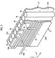
Fig. 2 is an enlarged perspective view of a lens unit. -
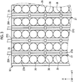
Fig. 3 is an enlarged plan view of the lens unit. -
Fig. 4 is a view illustrating an aspect in which the entire lower surface of the observation object holding unit is equally irradiated with excitation light in a state where a distance between a lower surface of an observation object holding unit and an upper surface of a lens holding part coincides with the focal length of a refractive index distribution type lens. -
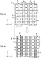
Fig. 5 is a view illustrating a lens unit, a moving mechanism, and a movement controller.Figs. 6A and 6B are views for illustrating the movement of the lens unit,Fig. 6A illustrates a case where the lens unit is at a first position, andFig. 6B illustrates a case where the lens unit is located at a second position. -
Fig. 7 is a block diagram of the fluorescence reading device. -
Fig. 8 is a flowchart illustrating a procedure in a case where a fluorescence image is captured by the fluorescence reading device. -
Fig. 9 is a view illustrating an example in which emission ends are alternately disposed in two lens holding parts separating adjacent lens arrays from each other. -
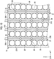
Fig. 10 is a view illustrating an example in which emission ends are disposed in a staggered lattice pattern with respect to the two lens holding parts separating the adjacent lens arrays from each other. -
Fig. 11 is a view illustrating a fluorescence reading device of a second embodiment. -
Fig. 12 is a plan view illustrating a lens unit of the second embodiment and optical fiber sub-bundles disposed around the lens unit. -
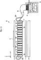
Fig. 13 is a view illustrating a fluorescence reading device of a third embodiment. -
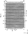
Fig. 14 is a plan view illustrating a lens unit of the third embodiment and optical fiber sub-bundles disposed around the lens unit. -
Fig. 15 is a cross-sectional view illustrating a light guide unit of a fourth embodiment. -
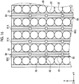
Fig. 16 is a plan view illustrating the light guide unit of the fourth embodiment. -
Fig. 17 is an enlarged exploded perspective view of a lens holding part of the fourth embodiment. -
Fig. 18 is a table illustrating an example of reflectivities of reflecting members. -
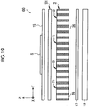
Fig. 19 is a view illustrating a fluorescence reading device of a fifth embodiment. -
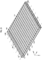
Fig. 20 is a perspective view of a light guide plate as seen from an upper surface side. -
Fig. 21 is a perspective view of the light guide plate as seen from a lower surface side. -
Fig. 22 is a view illustrating the detailed arrangement of the light guide plate and a light source. -
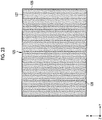
Fig. 23 is a plan view illustrating a light guide plate in which second openings are not formed. -
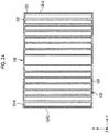
Fig. 24 is a plan view illustrating a light guide plate in which the exclusive area of first openings at a central part is made larger than that at an end part, on an upper surface of a transmission plate that faces an observation object. -
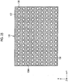
Fig. 25 is a plan view illustrating a light guide plate in which circular first openings are formed. - As illustrated in
Fig. 1 , afluorescence reading device 10 is a device that detects fluorescence that is excited with excitation light and emitted from an observation object S, and generates and displays a fluorescence image according to this fluorescence. Thefluorescence reading device 10 includes an observationobject holding unit 15, alens unit 16, an excitationlight cutoff filter 17, a detectingunit 18, alight source 19, and anoptical fiber bundle 20 equivalent to a light guide unit. - The observation
object holding unit 15, thelens unit 16, the excitationlight cutoff filter 17, and the detectingunit 18 are disposed in this order in a Z-axis direction. Additionally, therespective parts 15 to 18 all have outer shapes that are parallel plate shapes, and are disposed such that upper surfaces and lower surfaces thereof become parallel to an XY plane including an X-axis and a Y-axis orthogonal to this. In addition, an X-axis direction corresponds to a first direction, and a Y-axis direction corresponds to a second direction. A Z-axis is an axis perpendicular to both the X-axis and the Y-axis. - The observation
object holding unit 15 holds the observation object S. More specifically, the observationobject holding unit 15 has the observation object S placed on the upper surface thereof. The observationobject holding unit 15 is formed of materials, such as glass or resin, which allow the excitation light and the fluorescence to be transmitted therethrough. - The
lens unit 16 is disposed between the observationobject holding unit 15 and the excitationlight cutoff filter 17 and further between the observationobject holding unit 15 and the detectingunit 18. Thelens unit 16 focuses the fluorescence on the detectingunit 18. - The
lens unit 16 has alens array 25. In thelens array 25, a plurality of refractive indexdistribution type lenses 26 are arranged in one row in a line in the X-axis direction that is the first direction (refer toFig. 2 and the like). Thelens unit 16 has a configuration in which a plurality of thelens arrays 25 are arranged in the Y-axis direction that is the second direction. That is, thelens unit 16 has a configuration in which the plurality of refractive indexdistribution type lenses 26 are two-dimensionally arranged in the XY plane. In addition, in thelens array 25, the refractive indexdistribution type lenses 26 may be arranged in two or more rows. - Each refractive index
distribution type lens 26 has a columnar outer shape of which the diameter is, for example, about 0.1 mm to 5 mm. The refractive indexdistribution type lens 26 is, specifically, a SELFOC (registered trademark) lens. - Moreover, the
lens unit 16 has alens holding part 27. Thelens holding part 27 is constituted of a pair of parallel flat plates extending in the X-axis direction, and sandwiches and holds the lens arrays 25 (refer toFig. 2 ). Thelens arrays 25 adjacent to each other in the Y-axis direction are separated from each other by twolens holding parts 27. Thelens holding parts 27 are formed of, for example, black resin, and has a fluorescence shielding property. - The excitation
light cutoff filter 17 has a spectral characteristic in which that the excitation light is not literally transmitted, and hinders incidence of the excitation light to the detectingunit 18. Meanwhile, the excitationlight cutoff filter 17 has a spectral characteristic that the fluorescence is transmitted from the observation object S. For the fluorescence image generated on the basis of the fluorescence, the excitation light becomes noise. Hence, an S/N ratio of the fluorescence image can be improved by providing the excitationlight cutoff filter 17. - In the detecting
unit 18, a plurality of detecting elements are two-dimensionally arranged. Each detecting element detects the fluorescence transmitted through the observationobject holding unit 15, thelens unit 16, and the excitationlight cutoff filter 17, and outputs a detection signal. The detectingunit 18 has a detection plane for detecting the fluorescence on the upper surface thereof. The detectingunit 18 is, for example, a flat panel detector (FPD), a charge-coupled device (CCD) type detector, a complementary metal-oxide semiconductor (CMOS) type detector, or the like. The size of the detecting elements that constitute the detectingunit 18 is, for example, 50 square µm to 100 square µm. Additionally, although the size of the detection plane of the detectingunit 18 can be appropriately changed in accordance with to the size of the observation object S, the size is, for example, 10 cm square. - The
light source 19 has a light-emittingelement 30, an excitationlight transmission filter 31, a condensinglens 32, and acase 33. The light-emittingelement 30 is a light-emitting diode (LED), and emits the excitation light toward the excitationlight transmission filter 31. The excitationlight transmission filter 31 has a spectral characteristic that only light of a preset wavelength range including a central wavelength of the excitation light is transmitted therethrough. That is, in the excitation light emitted from the light-emittingelement 30, an excessive component that may become the noise of the fluorescence image is removed by the excitationlight transmission filter 31. The condensinglens 32 condenses the excitation light transmitted through the excitationlight transmission filter 31 toward anincident end 34 of theoptical fiber bundle 20. - The
case 33 has a light shielding property. Thecase 33 accommodates the light-emittingelement 30, the excitationlight transmission filter 31, the condensinglens 32, and theincident end 34 of theoptical fiber bundle 20. - The
optical fiber bundle 20 guides the excitation light that is incident from theincident end 34. At theincident end 34 of theoptical fiber bundle 20, a plurality of well-known optical fibers each having a core and a clad are bundled. The bundledoptical fiber bundle 20 is wired toward thelens unit 16. Then, the bundledoptical fiber bundle 20 is subdivided into a predetermined number ofoptical fiber sub-bundles 20A (refer toFig. 2 ) in front of thelens unit 16. In addition, the predetermined number is within a range of, for example, one to several tens. In a case where the predetermined number is one, anoptical fiber sub-bundle 20A becomes an optical fiber itself. However, in order to distinguish the optical fiber sub-bundle from theoptical fiber bundle 20, optical fiber sub-bundles also including one optical fiber are referred to as theoptical fiber sub-bundles 20A for convenience. - In
Figs. 2 and3 , the optical fiber sub-bundles 20A are buried in thelens holding parts 27 of thelens unit 16. Specifically, the optical fiber sub-bundles 20A are fitted intoattachment grooves 35 formed in thelens holding parts 27 as illustrates by arrows inFig. 2 . - The
attachment grooves 35 are formed onsurfaces 27B opposite tosurfaces 27A of thelens holding parts 27 that hold eachlens array 25 therebetween. Eachattachment groove 35 is formed at the same position in the twolens holding parts 27 separating theadjacent lens arrays 25 from each other. That is, theattachment groove 35 has a so-called half-split shape in which a cylindrical cavity for accommodating eachoptical fiber sub-bundle 20A is formed by the twolens holding parts 27 being joined to each other in thesurfaces 27B. - The
attachment groove 35 has a portion that extends parallel to the X-axis direction from an end part of eachlens holding part 27, and a portion that rises from a portion perpendicularly in the Z-axis direction. An end part including anemission end 36 of theoptical fiber sub-bundle 20A is located in the portion of theattachment groove 35 that rises perpendicularly in the Z-axis direction. Theemission end 36 is exposed to a surface (hereinafter, an upper surface) 27C of thelens holding part 27 that faces the observationobject holding unit 15. In addition, theattachment groove 35 may be raised at an obtuse angle from the portion extending parallel to the X-axis direction such that a bending load is not applied to theoptical fiber sub-bundle 20A. - The excitation light from the
light source 19 is radiated toward the observation object S of the observationobject holding unit 15 from theemission end 36. The surface of the observation object S in contact with the observationobject holding unit 15 is irradiated with the excitation light. Then, the fluorescence is emitted from the surface of the observation object S that is irradiated with this excitation light and is in contact with the observationobject holding unit 15. - The
attachment grooves 35 are formed in all thelens holding parts 27 other than thelens holding parts 27 disposed at both ends with respect to the Y-axis direction. Additionally, the portions of theattachment grooves 35 that rise perpendicularly in the Z-axis direction are formed at positions parallel to the Y-axis direction at equal intervals with respect to the X-axis direction. For this reason, emission ends 36 are disposed all thelens holding parts 27 other than thelens holding parts 27 disposed at both ends with respect to the Y-axis direction, and are disposed at equal intervals at on a straight line parallel to the X-axis direction, and is disposed at equal intervals at a straight line parallel to the Y-axis direction. Hence, it can be said that the emission ends 36 are equally disposed within the XY plane (theupper surfaces 27C of the lens holding parts 27). In addition, the numbers ofoptical fiber sub-bundles 20A to be buried in the twolens holding parts 27 separating theadjacent lens arrays 25 from each other are several to several tens. - As illustrated in
Fig. 4 , a distance H between the lower surface of the observationobject holding unit 15 and theupper surface 27C of eachlens holding part 27 coincides with the focal length (for example, 20 mm) of the refractive indexdistribution type lens 26. In this state, the excitation light illustrated by one-dot chain lines is emitted at a predetermined emission angle from eachemission end 36, and is equally radiated to the entire lower surface of the observationobject holding unit 15. In other words, in a case where the distance H between the lower surface of the observationobject holding unit 15 and theupper surface 27C of thelens holding part 27 is made to coincide with the focal length of each the refractive indexdistribution type lens 26, the number and the arrangement of emission ends 36, and the emission angle are set such that the excitation light is equally radiated to the entire lower surface of the observationobject holding unit 15. - In
Fig. 5 , the movingmechanism 40 is connected to thelens unit 16. The movingmechanism 40 moves thelens unit 16 in Y-axis direction. The movingmechanism 40 is a well-known mechanism, such as a cam, which converts a rotational motion of a motor into a translational motion. Amovement controller 41 that controls the operation of the movingmechanism 40 is connected to the movingmechanism 40. - Although the fluorescence from the observation object S is focused on the detecting
unit 18 by the refractive indexdistribution type lenses 26 of thelens unit 16, a portion thereof is shielded by thelens holding part 27 having a fluorescence shielding property and does not reach the detectingunit 18. Hence, the fluorescence image has no image information of a portion corresponding to thelens holding part 27 as it is. Thus, themovement controller 41 moves thelens unit 16 to a plurality of positions in the Y-axis direction through the movingmechanism 40. -
Fig. 6 has illustrated a case (Φ ≥ 2W) where a diameter Φ of each refractive indexdistribution type lens 26 is equal to or more than awidth 2W equivalent to two times the width W of thelens holding part 27 in the Y-axis direction. In this case, themovement controller 41 moves thelens unit 16 from a first position illustrated inFig. 6A to a second position illustrated inFig. 6B through the movingmechanism 40. The second position is, specifically, a position moved by a distance of L/2 in the Y-axis direction from the first position, in a case where a center-to-center distance between theadjacent lens array 25 is L. By doing so, eachlens array 25 is disposed at the second position, in a portion where eachlens holding part 27 is present at the first position. Hence, a situation where a portion of the fluorescence from the observation object S is shielded by thelens holding part 27 and does not reach the detectingunit 18 is solved. - In a case where the diameter Φ of the refractive index
distribution type lens 26 is smaller than 2W (Φ < 2W), themovement controller 41 moves thelens unit 16 to three or more positions from the first position to the second position, from the second position to a third position, and ... through the movingmechanism 40. For example, in a case where the diameter Φ of the refractive indexdistribution type lens 26 is equal to W, themovement controller 41 moves thelens unit 16 from the first position to the second position and from the second position to the third position by W through the movingmechanism 40. - The
movement controller 41 moves thelens unit 16 to the last position through the movingmechanism 40 and then returns thelens unit 16 to the first position again. - In
Fig. 7 , thefluorescence reading device 10 includes astorage unit 50, a central processing unit (CPU) 51, adisplay unit 52, and anoperating unit 53 in addition to the aforementioned detectingunit 18,light source 19, and movingmechanism 40. Thestorage unit 50 is, for example, a hard disk drive or the like, and stores anoperation program 54. By starting theoperation program 54, theCPU 51 functions as alight source controller 60, adetection controller 61, animage generation unit 62, and adisplay controller 63, including theaforementioned movement controller 41. - The
light source controller 60 controls the operation of thelight source 19, specifically, ON/OFF of the light-emittingelement 30 of thelight source 19. Thedetection controller 61 controls the operation of the detectingunit 18, specifically, the output operation of detection signals of the fluorescence by the detecting elements of the detectingunit 18. Theimage generation unit 62 generates the fluorescence image on the basis of the detection signals of the fluorescence from the detectingunit 18. Thedisplay controller 63 outputs the fluorescence image generated by theimage generation unit 62 to thedisplay unit 52, such as a liquid crystal display. - The
detection controller 61 makes the detectingunit 18 detect the fluorescence to output the detection signals at each position of thelens unit 16 moved by the movingmechanism 40. Theimage generation unit 62 synthesizes the detection signals detected each time at each position to generate one fluorescence image. - Alternatively, the
detection controller 61 makes the detectingunit 18 expose the fluorescence continuously from a first position to the last position, to output the detection signals, without making the detectingunit 18 output the detection signals at each position of thelens unit 16 moved by the movingmechanism 40. In this case, theimage generation unit 62 generates one fluorescence image on the basis of the detection signals from the detectingunit 18 without carrying out the processing in which the detection signals detected each time at each position as described above are synthesized. - The operating
unit 53 is, for example, well-known input devices, such as a keyboard and a mouse. The operatingunit 53 is operated in a case where a startup instruction of theoperation program 54, an imaging instruction for the fluorescence image, or the like is input. - Next, the operation of the
fluorescence reading device 10 having the above configuration will be described with reference to a flowchart ofFig. 8 . In a case where the fluorescence image is captured by thefluorescence reading device 10, the observation object S is first placed on an upper surface of the observation object holding unit 15 (Step ST100). Next, the imaging instruction for the fluorescence image is input via the operating unit 53 (Step ST110). - In a case where the imaging instruction is input via the operating
unit 53, the excitation light is emitted from thelight source 19 under the control of thelight source controller 60. The excitation light is guided by theoptical fiber bundle 20, and is radiated toward the observation object S from the emission ends 36 of theoptical fiber sub-bundles 20A exposed to theupper surfaces 27C of the lens holding parts 27 (Step ST120). - The fluorescence is emitted from the observation object S by the radiation of the excitation light. The fluorescence is radiated by the detecting
unit 18 via thelens unit 16 and the excitationlight cutoff filter 17. This fluorescence is detected by the detectingunit 18 under the control of the detection controller 61 (Step ST130). - Subsequently, the
lens unit 16 is moved through the movingmechanism 40 under the control of the movement controller 41 (Step ST140). A series of processing in these steps ST120 to ST140 is continued until thelens unit 16 is returned to the first position (YES in Step ST150). - The detection signals based on the basis of the fluorescence at a plurality of positions including the first position are output from the detecting
unit 18 until thelens unit 16 is returned to the first position. In the example illustrated inFig. 6 , two detection signals based on the fluorescence at the first position and the second position are output. - After the
lens unit 16 is returned to the first position, in theimage generation unit 62, one fluorescence image is generated on the basis of the plurality of detection signals at individual positions, which are output from the detecting unit 18 (Step ST160). The generated fluorescence image is displayed on thedisplay unit 52 under the control of the display controller 63 (Step ST170). - In the present example, the optical fiber bundle 20 (optical fiber sub-bundles 20A), which guides the excitation light emitted from the
light source 19 and radiates the guided excitation light toward the surface of the observation object S that faces thelens unit 16, is provided. For this reason, it is not necessary to dispose thelight source 19 between the observationobject holding unit 15 and thelens unit 16. That is, it is not necessary to provide a space equivalent to thelight source 19 between the observationobject holding unit 15 and thelens unit 16. For this reason, a distance between thelens unit 16 and the observation object S can be narrowed to a distance according to the focal length of the refractive indexdistribution type lens 26. Hence, it is possible to focus the fluorescence emitted from the observation object S on the detectingunit 18 without blurring the fluorescence, and the image quality of the fluorescence image can be excellently maintained. - The
optical fiber bundle 20 used as the light guide unit is general as an industrial product, is relatively inexpensive, and is easily obtained. Additionally, processing, such as bundling or subdividing into theoptical fiber sub-bundles 20A, can be easily performed. For this reason, there is little concern about an increase in component cost and complication and a manufacturing process. - Moreover, in the present example, the optical fiber sub-bundles 20A are buried in the
lens holding parts 27, and the optical fiber sub-bundles 20A are integrated with thelens holding parts 27 by exposing the emission ends 36 of theoptical fiber sub-bundles 20A to theupper surfaces 27C of thelens holding parts 27. For that reason, asFig. 4 illustrated, the distance between thelens unit 16 and the observation object S can be narrowed such that the distance H between the lower surface of the observationobject holding unit 15 and theupper surface 27C of eachlens holding part 27 coincides with the focal length of the refractive indexdistribution type lens 26. - Moreover, in the present example, since the emission ends 36 are equally disposed within the
upper surface 27C of thelens holding part 27, the quantity of light of the excitation light radiated to the observation object S also becomes uniform. Hence, the excitation light can be uniformly radiated to the observation object S, and a fluorescence image with more excellent image quality can be obtained. - In addition, in a case where the excitation light emitted from each
emission end 36 has a sufficient quantity of light, the number of emission ends 36 to be exposed to theupper surfaces 27C of thelens holding parts 27 can be reduced. For example, the emission ends 36 may not be disposed in all thelens holding parts 27 other than thelens holding parts 27 disposed at both ends with respect to the Y-axis direction. Specifically, as illustrated inFig. 9 , the emission ends 36 are alternately disposed in the twolens holding parts 27 separating theadjacent lens arrays 25 from each other. - Additionally, the emission ends 36 may not be disposed at equal intervals on the straight line parallel to the Y-axis direction. For example, as illustrated in
Fig. 10 , the emission ends 36 may be disposed in a staggered lattice pattern in the twolens holding parts 27 separating theadjacent lens arrays 25 from each other. The emission ends 36 may also be disposed in a staggered lattice pattern with respect to the X-axis direction. - Also in the example illustrated in these
Figs. 9 and10 , there is no change in the emission ends 36 being equally disposed within theupper surface 27C of thelens holding part 27. Hence, the effect that the excitation light can be uniformly radiated to the observation object S is obtained. - A second embodiment illustrated in
Figs. 11 and12 is an example in which the emission ends 36 of the optical fiber sub-bundles 20A are disposed at an outer periphery of the lens unit, and the emission ends 36 are directed to the observationobject holding unit 15. - In
Fig. 11 , in afluorescence reading device 70 of the present embodiment, alens unit 72 in which the optical fiber sub-bundles 20A are not buried inlens holding parts 71 is used. The emission ends 36 of the optical fiber sub-bundles 20A are disposed at the outer periphery of thelens unit 72. The emission ends 36 are directed to the observationobject holding unit 15. Since the other components are the same as those of thefluorescence reading device 10 of the above first embodiment, the description thereof will be omitted. - As illustrated in
Fig. 12 , the emission ends 36 of the optical fiber sub-bundles 20A are disposed at equal intervals so as to surround the entire outer periphery of thelens unit 72. Specifically, the emission ends 36 are lined up at the same intervals as the diameter Φ of the refractive indexdistribution type lens 26 with respect to the X-axis direction. Additionally, with respect to the Y-axis direction, the emission ends 36 are lined up at intervals Φ+2W obtained by summing up the diameter Φ of the refractive indexdistribution type lens 26 and thewidth 2W equivalent to two times the width W of eachlens holding part 71 in the Y-axis direction. That is, the emission ends 36 are disposed at the same pitch as the array pitches of the refractive indexdistribution type lenses 26 in the X-axis direction and the Y-axis direction. - In this way, the emission ends 36 of the optical fiber sub-bundles 20A are disposed at the outer periphery of the
lens unit 72. Thus, it is not necessary to form theattachment grooves 35 for fitting theoptical fiber sub-bundles 20A into thelens holding parts 71, as in a case where theoptical fiber sub-bundles 20A of the above first embodiment are buried in thelens holding parts 27 and the emission ends 36 are exposed to theupper surfaces 27C. Hence, compared to the above first embodiment, the labor and cost of the processing of theattachment grooves 35 can be reduced. - In addition, in this case, the arrangement angle of the
optical fiber sub-bundles 20A with respect to the observationobject holding unit 15 is adjusted. More specifically, the portion of the observationobject holding unit 15 to be handled is assigned to individualoptical fiber sub-bundles 20A such that a certainoptical fiber sub-bundle 20A is directed toward an end part of the observationobject holding unit 15 and a certainoptical fiber sub-bundle 20A is directed toward a central part of the observationobject holding unit 15. Additionally, since the distance from eachemission end 36 becomes longer at the central part the observationobject holding unit 15 than at the end part of the observationobject holding unit 15 and the excitation light is attenuated, the quantity of light is increased by making the number of optical fibers that constitute theoptical fiber sub-bundles 20A that handle the central part larger than the number of optical fibers that constitute theoptical fiber sub-bundles 20A that handle the end part. By taking such measures, the excitation light having the same quantity of light is radiated to the entire lower surface of the observationobject holding unit 15, and the excitation light is uniformly radiated to the observation object S. - The third embodiment illustrated in
Figs. 13 and14 is an example in which the emission ends 36 of the optical fiber sub-bundles 20A are disposed at the outer periphery of thelens unit 16, and the emission ends 36 are directed not toward the observationobject holding unit 15 but toward the upper surfaces of the lens holding parts that face the observationobject holding unit 15. - In
Fig. 13 , afluorescence reading device 75 of the present embodiment is the same as the above second embodiment in that alens unit 77 in which the optical fiber sub-bundles 20A are not buried inlens holding parts 76, and the emission ends 36 of the optical fiber sub-bundles 20A are disposed at the outer periphery of thelens unit 77. However, the present embodiment is different from the above second embodiment in that the emission ends 36 are directed not toward the observationobject holding unit 15 but towardupper surfaces 76C of thelens holding parts 76 that face the observationobject holding unit 15. Since the other components are the same as those of thefluorescence reading device 10 of the above first embodiment, the description thereof will be omitted. - As illustrated in
Fig. 14 , similar to the above second embodiment, the emission ends 36 of the optical fiber sub-bundles 20A are disposed at equal intervals so as to surround the entire outer periphery of thelens unit 77. Additionally, similar to the above second embodiment, the intervals relating to the X-axis direction and the intervals related to the Y-axis direction are also respectively the diameter Φ of the refractive indexdistribution type lens 26, and intervals Φ+2W obtained by summing up thewidth 2W equivalent to two times the width W of eachlens holding part 76 in the Y-axis direction and the diameter Φ of the refractive indexdistribution type lens 26. - The
lens holding parts 76 are formed of a material that reflects the excitation light. Additionally, theupper surfaces 76C of thelens holding parts 76 are subjected to, for example, roughening processing, such as of sandblasting, and is made into a scattering surface, as illustrated by hatching. In this case, the excitation light emitted from the emission ends 36 is reflected and scattered by theupper surfaces 76C of thelens holding parts 76, and is radiated toward the observationobject holding unit 15 from theupper surfaces 76C of thelens holding parts 76. - Even with the above configuration, similar to the above second embodiment, the effect that the labor and cost of the processing of the
attachment grooves 35 can be reduced compared to the above first embodiment can be obtained. - Since the
upper surfaces 76C of thelens holding parts 76 are made into the scattering surfaces, the excitation light having more uniform quantity of light can be radiated to a wider range of the observationobject holding unit 15. - In addition, even in this case, similar to the above second embodiment, the arrangement angle of the
optical fiber sub-bundles 20A with respect to theupper surfaces 76C of thelens holding parts 76 is adjusted such that the excitation light having the same quantity of light is radiated to the entire lower surface of the observationobject holding unit 15. Additionally, the quantity of light is increased by making the number of optical fibers that constitute theoptical fiber sub-bundles 20A that handle central parts of theupper surfaces 76C of thelens holding parts 76 larger than the number of optical fibers that constitute theoptical fiber sub-bundles 20A that handle end parts of theupper surfaces 76C. - Additionally, it is not necessary to form all the
lens holding parts 76 of the material that reflects the excitation light, and at least theupper surfaces 76C that reflect and scatter the excitation light may have a configuration in which the excitation light is reflected. For example, it is possible to coat theupper surfaces 76C with the material that reflects the excitation light. - The fourth embodiment illustrated in
Figs. 15 to 18 is an example in which two light guide paths formed by cavities, and a plurality of reflecting members disposed within the light guide paths constitute a light guide unit. - In
Figs. 15 to 17 , alight guide unit 80 of the fourth embodiment is constituted of a firstlight guide path 81, a secondlight guide path 82, a plurality ofbeam splitters 83 equivalent to the reflecting members, and atotal reflection mirror 84 that is also equivalent to a reflecting member (inFigs. 16 and17 , thebeam splitters 83 and thetotal reflection mirror 84 are not illustrated). The firstlight guide path 81 and the secondlight guide path 82 are cylindrical cavities formed withinlens holding parts 85, and allow the excitation light to pass therethrough. More specifically, the firstlight guide path 81 and the secondlight guide path 82 are formed in a half-split shape in bonding surfaces of the twolens holding parts 85 separating theadjacent lens arrays 25 from each other similar to theattachment groove 35 of the above first embodiment, and the cylindrical cavities are formed by the twolens holding part 85 being joined to each other. - The first
light guide path 81 extends in the X-axis direction, which is the first direction, within thelens holding parts 85. A plurality of the secondlight guide paths 82 are provided, and are disposed at intervals D in the X-axis direction. The plurality of secondlight guide paths 82 respectively communicate with the firstlight guide path 81 and one end of each thereof opens toward the observation object holding unit 15 (the observation object S is not illustrated). Additionally, the plurality of secondlight guide paths 82 are parallel to the Z-axis direction, and respectively intersect the firstlight guide path 81, which extends in the X-axis direction, at right angles. - The
beam splitters 83 and thetotal reflection mirror 84 are respectively disposed at intersection points between the firstlight guide path 81 and the plurality of secondlight guide paths 82. Thebeam splitters 83 and thetotal reflection mirror 84 are disposed so as to be tilted with respect to an optical axis of the excitation light (illustrated by arrows of one-dot chain lines), which passes through the firstlight guide path 81, at 45°. Thebeam splitters 83 transmit a portion of the excitation light passing through the firstlight guide path 81, and reflect the remainder of the excitation light toward the secondlight guide paths 82. Thetotal reflection mirror 84 is located on the most downstream side of the firstlight guide path 81, and reflect all the excitation light passing through the firstlight guide path 81 toward the secondlight guide paths 82. - The end of the first
light guide path 81 on the most upstream side opposite to a side where thetotal reflection mirror 84 is disposed opens to end surfaces of thelens holding parts 85. Alight source 86 that emits the excitation light is disposed at a position that faces anopening 81A of this firstlight guide path 81. Thelight source 86 has the light-emittingelement 30 and the excitationlight transmission filter 31, similar to the light sources 19 (refer toFig. 1 and the like) of the above embodiments. However, thelight source 86 has acollimating lens 87 instead of the condensinglens 32, and has a configuration in which the light-emittingelement 30, the excitationlight transmission filter 31, and thecollimating lens 87 are accommodated in acase 88 having a light shielding property. The collimatinglens 87 makes the excitation light, which is emitted from the light-emittingelement 30 and transmitted through the excitationlight transmission filter 31, into collimated light, and makes the collimated light incident on the firstlight guide path 81. - A portion of the excitation light incident on the first
light guide path 81 is reflected by theindividual beam splitters 83 and is incident the secondlight guide paths 82. Additionally, the excitation light is totally reflected by thetotal reflection mirror 84, and is incident on the secondlight guide paths 82. The excitation light incident on the secondlight guide paths 82 is emitted from openings of the secondlight guide paths 82, and is radiated to the lower surface of the observationobject holding unit 15. In addition, although illustration is omitted, the scattering plate for making excitation light collimated by the collimatinglens 87 into scattered light are disposed in the openings of the secondlight guide paths 82. - The intervals D of the adjacent second
light guide paths 82 are all equal to each other. That is, the secondlight guide paths 82 are formed at equal intervals with respect to the X-axis direction. Additionally, asFig. 16 illustrated, the secondlight guide paths 82 are formed in all thelens holding parts 85 other than thelens holding part 85 disposed at both ends with respect to the Y-axis direction, similar to the emission ends 36 illustrated inFig. 3 of the above first embodiment. Moreover, the secondlight guide paths 82 are formed at equal intervals on a straight line parallel to the Y-axis direction. That is, the lens unit in this case has a configuration in which the emission ends 36 are substituted with the secondlight guide paths 82, in thelens unit 16 illustrated inFig. 3 or4 . Hence, it can be said that the plurality of secondlight guide paths 82 are equally disposed within the XY plane (theupper surfaces 85C of the lens holding parts 85). - As illustrated in Table 90 of
Fig. 18 , the reflectivities of thebeam splitters 83 are adjusted such that the light quantities of the excitation light that passes through the plurality of secondlight guide paths 82 become the same. Table 90 shows reflectivities of theindividual beam splitters 83 in the case of the number of the reflecting members (thebeam splitters 83 and the total reflection mirror 84) (the number of the second light guide paths 82) = 10, and reflected light quantities and transmitted light quantities in a case where the light quantity of the excitation light that is first incident on the firstlight guide path 81 from thelight source 86 is 100. Additionally, Table 90 shows that, as No. is smaller, a reflecting mirror is at a position closer to thelight source 86 side, that is, at a position closer to the upstream side of the firstlight guide path 81. - The reflectivities increase toward the downstream side. The most downstream No. 10 is the
total reflection mirror 84, and the reflectivity thereof is 100%. In the example of Table 90, since the number of secondlight guide paths 82 = 10, the reflectivity is adjusted such that the light quantities (reflected light quantities) of the excitation light passing through the ten secondlight guide paths 82 are the same "10". - In addition, the expression the "light quantities of the excitation light that passes through the plurality of second
light guide paths 82 are same" includes not only completely the same but also allow some variations. In the example of Table 90, although the reflected light quantities of thebeam splitter 83 of Nos. 1, 3, 6, and 7 are "10.00", the reflected light quantity of Nos. 2, 9, and 10 are "9.99", the reflected light quantity of No. 4 is "10.01", the reflected light quantities of Nos. 5 and 8 are "10.02", and somewhat vary from each other. However, since these reflected light quantities all become "10" in a case where the reflected light quantities are rounded off at two decimal points, it is assumed that the "light quantities of the excitation light that passes through the plurality of secondlight guide paths 82 are same". In addition, a range where the variations are allowed is, for example, a range where the reflected light quantities coincide with each other in a case where the reflected light quantities are rounded off at two decimal points. This is based on manufacturing errors of the reflecting members, such as thebeam splitters 83 and thetotal reflection mirror 84, being about ±5%. - In this way, since the
light guide unit 80 is constituted of the firstlight guide path 81, the secondlight guide paths 82, thebeam splitters 83, and thetotal reflection mirror 84, it is not necessary to prepare theoptical fiber bundle 20 unlike the above individual embodiments. For this reason, the cost for theoptical fiber bundle 20 can be reduced. - Since the reflectivities of the
beam splitters 83 are adjusted such that the light quantities of the excitation light that passes through the plurality of secondlight guide paths 82 become the same and the plurality of secondlight guide paths 82 are equally disposed, the excitation light can be uniformly radiated to the observation object S. - For example, similar to the example illustrated in
Fig. 9 , the secondlight guide paths 82 may not be disposed in all thelens holding parts 85 other than thelens holding parts 85 disposed at both ends with respect to the Y-axis direction. Additionally, similar to the example illustrated inFig. 10 , the secondlight guide paths 82 may be disposed in a staggered lattice pattern in the twolens holding parts 85 separating theadjacent lens arrays 25 from each other. - Although the
light source 86 is disposed at the position that faces the opening of the firstlight guide path 81, in this case, it is necessary to dispose thelight source 86 by the amount equivalent to the firstlight guide path 81. Thus, thelight source 19 of each of the above embodiments may be used instead of thelight source 86, and the emission ends 36 of theoptical fiber sub-bundles 20A may be disposed at positions that face the opening of the firstlight guide path 81. In this case, the optical fiber bundle 20 (optical fiber sub-bundles 20A) is also included in thelight guide unit 80. - The second
light guide paths 82 need not be orthogonal to the firstlight guide path 81. The secondlight guide paths 82 may intersect the firstlight guide path 81 at an acute angle or an obtuse angle. - A fifth embodiment illustrated in
Figs. 19 to 25 is an example in which a light guide plate having a parallel plate shape constitute a light guide unit. - In
Fig. 19 , afluorescence reading device 100 of the present embodiment includes alight guide plate 101 having a parallel plate shape, as the light guide unit. Thelens unit 72 of the above second embodiment is used for the lens unit. Thelight guide plate 101 is disposed between the observationobject holding unit 15 and thelens unit 72. - As illustrated in
Figs. 20 and21 , thelight guide plate 101 has atransmission plate 110, a firstreflective film 111, a secondreflective film 112, thefirst openings 113, andsecond openings 114. Similar to the observationobject holding unit 15, thetransmission plate 110 is formed of materials, such as glass or resin, which that allows the excitation light and the fluorescence to be transmitted therethrough. The firstreflective film 111 and the secondreflective film 112 are any one of aluminum films, gold films, silver films, and dielectric multilayer films, and reflect the excitation light. The firstreflective film 111 is formed on a surface (hereinafter, an upper surface) 110A of thetransmission plate 110 that faces the observationobject holding unit 15. The secondreflective film 112 is formed on a surface (hereinafter, a lower surface) 110B of thetransmission plate 110 that faces thelens unit 72. - The
first openings 113 are portions in which the firstreflective film 111 is missing in a slit shape on theupper surface 110A of thetransmission plate 110. Thesecond openings 114 are portions in which the secondreflective film 112 is missing a slit shape at positions that face the firstreflective film 111, on thelower surface 110B of thetransmission plate 110. For this reason, thefirst openings 113 and thesecond openings 114 transmit the excitation light. - The
first openings 113 and thesecond openings 114 are formed at positions corresponding to thelens arrays 25. That is, the width of eachfirst opening 113 in the Y-axis direction is the same as the diameter Φ of the refractive indexdistribution type lens 26, and the intervals of the adjacentfirst openings 113 in the Y-axis direction are the same as thewidth 2W equivalent to the twolens holding parts 71 in the Y-axis direction. The length of thefirst opening 113 in the X-axis direction is the same as the length of eachlens array 25 in the X-axis direction. The same applies to thesecond openings 114. In addition, inFig. 20 , in order to avoid complication, only twosecond openings 114 disposed at both ends with respect to the Y-axis direction are drawn. Additionally, inFig. 21 , for the same reason, only twofirst openings 113 disposed at both ends with respect to the Y-axis direction are drawn. - In this case, as illustrated by arrows of one-dot chain lines, the excitation light is incident from both side surfaces 110C and 110D on the short side of the
transmission plate 110 parallel to the X-axis direction. In more detail, as illustrated inFig. 22 ,the excitation light is emitted fromlight sources 120 disposed at positions that face both the side surfaces 110C and 110D, and is incident on both the side surfaces 110C and 110D. Although only onelight source 120 is drawn for each of both the side surfaces 110C and 110D inFig. 22 , a plurality of thelight sources 120 are arranged at equal intervals in the X-axis direction in practice. For this reason, as illustrated by one-dot chain lines illustrated inFigs. 20 and21 , the excitation light is equally incident on both the side surfaces 110C and 110D. - Each
light source 120 has the light-emittingelement 30, the excitationlight transmission filter 31, and the condensinglens 32, similar to the light sources 19 (refer toFig. 1 and the like) of the first to third embodiments. However, thelight source 120 has a configuration that there is no incident end 34 of theoptical fiber bundle 20 unlike thelight source 19 and the light-emittingelement 30, the excitationlight transmission filter 31, and the condensinglens 32 are accommodated in acase 121 having a light shielding property. The distances of thelight source 120 from both the side surfaces 110C and 110D are adjusted such that the condensinglens 32 is brought into a focus on both the side surfaces 110C and 110D. - As illustrated by arrows of one-dot chain lines, the
light guide plate 101 propagates the excitation light, which is incident from the side surfaces 110C and 110D of thetransmission plate 110, through the inside of thetransmission plate 110 while reflecting the excitation light with the firstreflective film 111 and the secondreflective film 112, and emits a portion of excitation light, which is propagated through the inside of thetransmission plate 110, toward the observation object holding unit 15 (the observation object S is not illustrated) through thefirst openings 113. Since thefirst openings 113 are formed in a slit shape that imitates thelens arrays 25, the excitation light is also formed in a slit shape that imitates thelens arrays 25, and is radiated to the observationobject holding unit 15. Although the excitation light is also emitted toward thelens unit 72 through thesecond openings 114, since this excitation light is cut by the excitationlight cutoff filter 17 and does not reach the detectingunit 18, there is no influence on the image quality of the fluorescence image. - Additionally, a moving mechanism having the same configuration as the moving
mechanism 40 is connected to thelight guide plate 101. Thelight guide plate 101 moves in synchronization with the movement of thelens unit 72 under the control of themovement controller 41 through this moving mechanism. Accordingly, the excitation light is selectively radiated to the position of the observationobject holding unit 15 corresponding to thelens arrays 25, and the fluorescence is radiated from the observation object S to which the excitation light is selectively radiated to the detectingunit 18. - The
light guide plate 101 is disposed between the observationobject holding unit 15 and thelens unit 72. For this reason, constraints for narrowing the distance between thelens unit 72 and the observation object S increase compared to the above first to fourth embodiments in which there is nothing present between the observationobject holding unit 15 and the lens unit. However, since thelight guide plate 101 has the parallel plate shape and the thickness thereof can be relatively thin as several millimeters, and there are fewer constraints for narrowing the distance between thelens unit 72 and the observation object S than providing the space equivalent to the light source being disposed between the observation object holding unit and the lens unit as in the related art. Hence, the distance between thelens unit 72 and the observation object S can be narrowed to the distance according to the focal length of the refractive indexdistribution type lens 26, and it is possible to focus the fluorescence emitted from the observation object S on the detectingunit 18 without blurring. - Here, a case where a phosphor sheet including a photostimulable phosphor layer is used as the observation object S is considered. In addition, the phosphor sheet is, for example, a sheet on which a radiographic image of a subject is recorded by receiving radiation transmitted through a subject, such as a patient, and a photostimulable phosphor is excited by radiation of excitation light to emit photostimulable emission light according to the radiographic image. The phosphor sheet is also referred to as an imaging plate.
- In a case where the excitation light is radiated to the entire phosphor sheet at once, for example, in a case where the lens unit is at the first position, fluorescence is emitted also from the portion of the phosphor sheet to be detected after the second position. Hence, it is impossible to detect the fluorescence after the second position.
- However, according to the
light guide plate 101, as mentioned above, the excitation light is selectively radiated to the position of the observationobject holding unit 15 corresponding to thelens arrays 25, and the fluorescence is radiated from the observation object S to which the excitation light is selectively radiated to the detectingunit 18. Hence, it is possible to avoid a situation where the excitation light is also radiated at once to portions other than the portion of the phosphor sheet corresponding to thelens arrays 25 and it is impossible to detect the fluorescence of the portion concerned. - Similar to the case of the above fourth embodiment, the
light source 19 of each of the above embodiments may be used instead of thelight source 120, and the emission ends 36 of theoptical fiber sub-bundles 20A may be disposed at both the side surfaces 110C and 110D. In this case, the light guide unit is constituted of the optical fiber bundle 20 (optical fiber sub-bundles 20A) and thelight guide plate 101. - In the
light guide plate 101 illustrated toFigs. 20 and21 , the plurality ofsecond openings 114 that are the portions in which the secondreflective film 112 are missing are formed in thelower surface 110B of thetransmission plate 110. However, as illustrated inFig. 23 , as long as the second reflective film may have the characteristics of reflecting the excitation light transmitting the fluorescence, thesecond openings 114 may not be provided. -
Fig. 23 illustrates a light guide plate 125 as seen from the lower surface side of the transmission plate. In the light guide plate 125, as illustrated by dotted lines,first openings 126 are formed in the upper surface of the transmission plate. However, as illustrated by hatching, the secondreflective film 127 is only formed on the whole on the lower surface of the transmission plate, and the second openings are not formed. In this case, the secondreflective film 127 is a dielectric multilayer film that reflects the excitation light and transmits the fluorescence. - According to the light guide plate 125 of
Fig. 23 , since the lower surface of the transmission plate is covered with the secondreflective film 127 and does not have the second openings, the excitation light is not emitted toward thelens unit 72 from thesecond openings 114 unlike thelight guide plate 101, and is emitted only from thefirst openings 126. Since the quantity of the excitation light that does not contribute to fluorescence excitation without being radiated to the observation object S becomes smaller than that in the case of thelight guide plate 101, the irradiation efficiency of the excitation light to the observation object S can be raised. Moreover, since the transmission of the excitation light to thelens unit 72 is prevented by the secondreflective film 127, that is, the secondreflective film 127 plays the role of the excitationlight cutoff filter 17, the excitationlight cutoff filter 17 can be omitted. Additionally, since the fluorescence is transmitted through the secondreflective film 127 and is radiated to the detectingunit 18, there is no influence on the generation of the fluorescence image. - The light guide plate has a configuration in which the excitation light incident from both the side surfaces of the transmission plate is propagated through the inside of the transmission plate and a portion of the excitation light is emitted from the first openings in the middle of the propagation. For this reason, there is concern that the light quantity of the excitation light is lower at the central part of the upper surface of the transmission plate than at the end parts of the upper surface of the transmission plate on both the side surfaces on which the excitation light is incident. Then, it is preferable to make the exclusive area of the first openings at the central part larger than that at the end parts on the upper surface of the transmission plate that faces the observation object S for the purpose of suppressing a decrease in the light quantity of the excitation light at this central part.
- In a
light guide plate 130 illustrated inFig. 24 , a firstreflective film 132 andfirst openings 133 are formed in anupper surface 131A of a transmission plate. The width of eachfirst opening 133 in the Y-axis direction is the narrowest on both side surfaces 131C and 131D of the transmission plate on which the excitation light is incident. The width gradually becomes wider toward the central part, and becomes the maximum at the central part. That is, in theupper surface 131A of the transmission plate, the exclusive area of thefirst openings 133 at the central part is large rather than that at the end parts. By adopting this configuration, a decrease in the light quantity of the excitation light at the central part can be suppressed. - The first openings and the second openings may not have the slit shapes. For example, as in a
light guide plate 135 illustrated inFig. 25 , in a firstreflective film 137 formed on anupper surface 136A of a transmission plate, circularly missing portions that imitate the shape of the refractive indexdistribution type lens 26 may be used asfirst openings 138. Thefirst openings 138 are alternately formed in portions corresponding to the refractive indexdistribution type lenses 26 with respect to the X-axis direction. In addition, in a case where thelight guide plate 135 is used, at individual positions, such as a first position, thelight guide plate 135 is moved in the X-axis direction by a distance equivalent to the diameter Φ of each refractive indexdistribution type lens 26, and the fluorescence before and after the movement is detected by the detectingunit 18. - In the case of the
light guide plate 135, simply by making the area of thefirst openings 138 larger toward the central part, the exclusive area of thefirst openings 138 at the central part can be made larger than that at the end parts, on theupper surface 136A of the transmission plate. In addition to or instead of this, the number of thefirst openings 138 may be increased toward the central part. - The above first to third embodiments may be appropriately combined with each other. For example, the above second embodiment and the above third embodiment are implemented in combination, the emission ends 36 of the optical fiber sub-bundles 20A are disposed at the outer periphery of the
lens unit 16, and the emission ends 36 are directed to the observationobject holding unit 15 and theupper surfaces 76C of thelens holding parts 76. Alternatively, the above first embodiment and the above second embodiment are implemented in combination, theoptical fiber sub-bundles 20A may be buried in thelens holding parts 27, the emission ends 36 may be exposed to theupper surfaces 27C of thelens holding parts 27, the emission ends 36 of theoptical fiber sub-bundles 20A may be disposed at the outer periphery of thelens unit 16, and the emission ends 36 may be directed to the observationobject holding unit 15. - It is needless to say that the invention is not limited to the above first to fifth embodiments and various configurations can be adopted unless departing from the scope of the invention.
-
- 10, 70, 75, 100: fluorescence reading device
- 15: observation object holding unit
- 16, 72, 77: lens unit
- 17: excitation light cutoff filter
- 18: detecting unit
- 19, 86, 120: light source
- 20: optical fiber bundle (light guide unit)
- 20A: optical fiber sub-bundle (light guide unit)
- 25: lens array
- 26: refractive index distribution type lens
- 27, 71, 76, 85: lens holding part
- 27A: surface of lens holding part that sandwiches and holds lens array
- 27B: surface opposite to surface of lens holding part that sandwiches and holds lens array
- 27C, 76C, 85C: surface (upper surface) of lens holding part that faces observation object holding unit
- 30: light-emitting element
- 31: excitation light transmission filter
- 32: condensing lens
- 33, 88, 121: case
- 34: incident end
- 35: attachment groove
- 36: emission end
- 40: moving mechanism
- 41: movement controller
- 50: storage unit
- 51: CPU
- 52: display unit
- 53: operating unit
- 54: operation program
- 60: light source controller
- 61: detection controller
- 62: image generation unit
- 63: display controller
- 80: light guide unit
- 81: first light guide path
- 81A: opening
- 82: second light guide path
- 83: beam splitter (reflecting member)
- 84: total reflection mirror (reflecting member)
- 87: collimating lens
- 90: table
- 101, 125, 130, 135: light guide plate (light guide unit)
- 110: transmission plate
- 110A, 131A, 136A: surface (upper surface) of and the transmission plate that faces observation object holding unit
- 110B: surface (lower surface) of transmission plate that faces lens unit
- 110C, 110D, 131C, 131D: side surface of transmission plate on which excitation light is incident
- 111, 132, 137: first reflective film
- 112, 127: second reflective film
- 113, 126, 133, 138: first opening
- 114: second opening
- S: observation object
- X: X-axis direction (first direction)
- Y: Y-axis direction (second direction)
- Z: Z-axis direction
- H: distance between lower surface of observation object holding unit and upper surface of lens holding part
- Φ: diameter of refractive index distribution type lens
- W: width of lens holding part in Y-axis direction
- L: center-to-center distance of adjacent lens arrays
- ST100 to ST170: step
- D: interval of the second light guide path in X-axis direction
Claims (19)
- A fluorescence reading device comprising:an observation object holding unit that holds an observation object that is excited with excitation light to emit fluorescence;a light source that emits the excitation light;a detecting unit in which detecting elements for detecting the fluorescence are two-dimensionally arranged;a lens unit which is disposed between the observation object holding unit and the detecting unit to focus the fluorescence on the detecting unit, and on which a plurality of refractive index distribution type lenses are two-dimensionally arranged; anda light guide unit that guides the excitation light emitted from the light source to radiate the guided excitation light toward a surface of the observation object that faces the lens unit.
- The fluorescence reading device according to claim 1,
wherein the lens unit is configured such that a plurality of lens arrays in each of which the plurality of refractive index distribution type lenses are arranged in a line in a first direction are arranged in a second direction orthogonal to the first direction,
wherein the lens unit further has a lens holding part, and
wherein the lens holding part includes a pair of parallel flat plates extending in the first direction and sandwiches and holds the lens arrays. - The fluorescence reading device according to claim 2,
wherein the light guide unit includes an optical fiber that guides the excitation light. - The fluorescence reading device according to claim 3,
wherein the light guide unit includes a plurality of the optical fibers,
wherein the optical fibers are buried in the lens holding part, and
wherein emission ends of the optical fibers are exposed to a surface of the lens holding part that faces the observation object holding unit. - The fluorescence reading device according to claim 4,
wherein the emission ends are equally disposed within the surface of the lens holding part that faces the observation object holding unit. - The fluorescence reading device according to claim 4 or 5,
wherein the emission ends are disposed in a staggered lattice shape within the surface of the lens holding part that faces the observation object holding unit. - The fluorescence reading device according to any one of claims 3 to 6,
wherein the light guide unit includes a plurality of the optical fibers, and wherein emission ends of the optical fibers are disposed at an outer periphery of the lens unit. - The fluorescence reading device according to claim 7,
wherein the emission ends are directed to the observation object holding unit. - The fluorescence reading device according to claim 7 or 8,
wherein the emission ends are directed to a surface of the lens holding part that faces the observation object holding unit, and
wherein the excitation light reflected by a surface of the lens holding part that faces the observation object holding unit is radiated toward the observation object holding unit. - The fluorescence reading device according to claim 9,
wherein the surface of the lens holding part that faces the observation object holding unit is used as a scattering surface that scatters the excitation light. - The fluorescence reading device according to any one of claims 3 to 10,
wherein the light source includes
a light-emitting element that emits the excitation light,
an excitation light transmission filter that transmits only light within a preset wavelength range including a central wavelength of the excitation light,
a condensing lens that condenses the excitation light transmitted through the excitation light transmission filter toward an incident end of the optical fiber, and
a light shielding case that accommodates the light-emitting element, the excitation light transmission filter, the condensing lens, and the incident end of the optical fiber. - The fluorescence reading device according to claim 2,
wherein the light guide unit includes
a first light guide path that is a cavity which is formed within the lens holding part and allows the excitation light to pass therethrough and that extends in the first direction within the lens holding part,
a plurality of second light guide paths that each communicate with the first light guide path are disposed at intervals with respect to the first direction, and each have one end opened toward the observation object holding unit, and
a plurality of reflecting members that are disposed at intersection points between the first light guide path and the plurality of second light guide paths, respectively, and reflect the excitation light passing the first light guide path toward the second light guide paths. - The fluorescence reading device according to claim 12,
wherein the reflecting members include beam splitters that transmit a portion of the excitation light and reflect the remainder of the excitation light toward the second light guide paths. - The fluorescence reading device according to claim 13,
wherein reflectivities of the beam splitters are adjusted such that light quantities of the excitation light that passes through the plurality of second light guide paths become the same, and the plurality of second light guide paths are equally disposed. - The fluorescence reading device according to claim 2,
wherein the light guide unit is a light guide plate having a parallel plate shape that is disposed between the observation object holding unit and the lens unit,
wherein the light guide plate has
a transmission plate that transmits the excitation light and the fluorescence,
a first reflective film that is formed on a surface of the transmission plate that faces the observation object holding unit and reflects the excitation light,
a second reflective film that is formed on a surface of the transmission plate that faces the lens unit and reflects the excitation light, and
a plurality of first openings that are portions in which the first reflective film is missing, in the surface of the transmission plate that faces the observation object holding unit, and
wherein the excitation light incident from a side surface of the transmission plate is propagated through an inside of the transmission plate while being reflected by the first reflective film and the second reflective film, and a portion of the excitation light propagated through the inside of the transmission plate is emitted toward the observation object holding unit through the first openings. - The fluorescence reading device according to claim 15,
wherein the light guide plate further has a plurality of the second openings that are portions in which the second reflective film is missing, in the surface of the transmission plate that faces the lens unit. - The fluorescence reading devices according to claim 16,
wherein the first reflective film and the second reflective film are aluminum films, gold films, silver films, or dielectric multilayer films. - The fluorescence reading device according to claim 15,
wherein the second reflective film is a dielectric multilayer film that reflects the excitation light and transmits the fluorescence. - The fluorescence reading device according to any one of claims 15 to 18,
wherein an exclusive area of the first openings at a central part is larger than that at an end part, in the surface of the transmission plate that faces the observation object.
Applications Claiming Priority (1)
| Application Number | Priority Date | Filing Date | Title |
|---|---|---|---|
| JP2017162487A JP6781121B2 (en) | 2017-08-25 | 2017-08-25 | Fluorescent reader |
Publications (3)
| Publication Number | Publication Date |
|---|---|
| EP3457117A2 true EP3457117A2 (en) | 2019-03-20 |
| EP3457117A3 EP3457117A3 (en) | 2019-06-26 |
| EP3457117B1 EP3457117B1 (en) | 2024-11-20 |
Family
ID=63524054
Family Applications (1)
| Application Number | Title | Priority Date | Filing Date |
|---|---|---|---|
| EP18189965.9A Active EP3457117B1 (en) | 2017-08-25 | 2018-08-21 | Fluorescence sensor with selfoc lens |
Country Status (3)
| Country | Link |
|---|---|
| US (1) | US10436715B2 (en) |
| EP (1) | EP3457117B1 (en) |
| JP (1) | JP6781121B2 (en) |
Families Citing this family (2)
| Publication number | Priority date | Publication date | Assignee | Title |
|---|---|---|---|---|
| CN116121051B (en) * | 2023-03-14 | 2023-09-01 | 鲲鹏(徐州)科学仪器有限公司 | Optical detection device |
| DE102024201487A1 (en) * | 2024-02-19 | 2025-08-21 | Robert Bosch Gesellschaft mit beschränkter Haftung | Optical unit for fluorescence image display, in particular for an analysis device for detecting pathogens, and method for producing an optical unit |
Citations (1)
| Publication number | Priority date | Publication date | Assignee | Title |
|---|---|---|---|---|
| US20170013212A1 (en) | 2015-07-08 | 2017-01-12 | Fujifilm Corporation | Image pickup device and method |
Family Cites Families (16)
| Publication number | Priority date | Publication date | Assignee | Title |
|---|---|---|---|---|
| US151900A (en) * | 1874-06-09 | Improvement in furnaces for roasting ores | ||
| JPH07107506B2 (en) * | 1986-12-19 | 1995-11-15 | グローリー工業株式会社 | Filamentous fluorescent substance detection device |
| JPH1151900A (en) * | 1997-08-07 | 1999-02-26 | Hitachi Electron Eng Co Ltd | Fluorescence detector |
| US6366338B1 (en) * | 1997-12-22 | 2002-04-02 | Citizen Watch Co. Ltd. | Line-scanning optical printer |
| US6192168B1 (en) * | 1999-04-09 | 2001-02-20 | The United States Of America As Represented By The Secretary Of The Navy | Reflectively coated optical waveguide and fluidics cell integration |
| JP2005181949A (en) * | 2003-01-29 | 2005-07-07 | Mitsubishi Rayon Co Ltd | Rod lens array manufacturing method and array jig used therefor, original plate cutting device, and end face cutting device |
| US20050181949A1 (en) * | 2004-02-13 | 2005-08-18 | Norton Lawrence H. | Method of improving turfgrass quality |
| US20060145100A1 (en) * | 2005-01-03 | 2006-07-06 | Kimberly-Clark Worldwide, Inc. | System and method for detecting an object on a moving web |
| JP4544182B2 (en) * | 2006-03-08 | 2010-09-15 | エプソンイメージングデバイス株式会社 | Illumination device, electro-optical device, and manufacturing method thereof |
| DE102006036171B4 (en) * | 2006-07-28 | 2008-10-09 | Analytik Jena Ag | Arrangement and method for multichannel fluorescence measurement in PCR samples |
| BRPI0908090A2 (en) * | 2008-02-25 | 2015-08-25 | Koninkl Philips Electronics Nv | Optical sensor and method for measuring light radiating from an analyte upon light excitation, and part kit |
| KR20100094851A (en) * | 2009-02-19 | 2010-08-27 | 삼성전자주식회사 | Light guide plate having a filled-in type light emitting structure, method of fabricating the same and display apparatus employing the same |
| EP2533033A4 (en) * | 2010-02-03 | 2013-07-10 | Uchrezhdenie Rossiiskoi Akademii Nauk Inst Molekulyarnoi Biolog Im V A Engelgardta Ran Imb Ran | Device for analyzing luminescent bio-microchips |
| JP2011196873A (en) * | 2010-03-19 | 2011-10-06 | Olympus Corp | Fluorescence detection method and fluorescence detection device |
| US9274290B2 (en) * | 2012-12-14 | 2016-03-01 | Cisco Technology, Inc. | Coupling light from a waveguide array to single mode fiber array |
| NZ775650A (en) * | 2015-05-04 | 2023-06-30 | Magic Leap Inc | Separated pupil optical systems for virtual and augmented reality and methods for displaying images using same |
-
2017
- 2017-08-25 JP JP2017162487A patent/JP6781121B2/en active Active
-
2018
- 2018-08-21 EP EP18189965.9A patent/EP3457117B1/en active Active
- 2018-08-24 US US16/112,048 patent/US10436715B2/en active Active
Patent Citations (2)
| Publication number | Priority date | Publication date | Assignee | Title |
|---|---|---|---|---|
| US20170013212A1 (en) | 2015-07-08 | 2017-01-12 | Fujifilm Corporation | Image pickup device and method |
| JP2017020822A (en) | 2015-07-08 | 2017-01-26 | 富士フイルム株式会社 | Imaging apparatus and method |
Also Published As
| Publication number | Publication date |
|---|---|
| EP3457117A3 (en) | 2019-06-26 |
| JP2019039827A (en) | 2019-03-14 |
| US10436715B2 (en) | 2019-10-08 |
| US20190064069A1 (en) | 2019-02-28 |
| EP3457117B1 (en) | 2024-11-20 |
| JP6781121B2 (en) | 2020-11-04 |
Similar Documents
| Publication | Publication Date | Title |
|---|---|---|
| CN102597745B (en) | Optical sensor system and sensing method based on attenuated total reflection | |
| US10342435B2 (en) | Photoacoustic measurement apparatus and probe for photoacoustic measurement apparatus | |
| JPH06300930A (en) | Uneven pattern input device | |
| TW200912281A (en) | Optical characteristic measuring apparatus and measuring method using light reflected from object to be measured | |
| US10231627B2 (en) | Probe | |
| WO2013128922A1 (en) | Acoustic wave detection probe and photoacoustic measurement device | |
| JP4975177B2 (en) | Imaging device | |
| JP2021015122A (en) | Chromatic confocal measuring device | |
| EP3457117B1 (en) | Fluorescence sensor with selfoc lens | |
| EP1913867A1 (en) | Optical measuring device and optical measuring method | |
| US10488820B2 (en) | Digital holographic image-taking apparatus | |
| TWI843197B (en) | Optical system for shape measuring device | |
| WO2013099981A1 (en) | Linear light irradiation device | |
| JP6180843B2 (en) | probe | |
| WO2018216118A1 (en) | Lighting device | |
| US11769984B2 (en) | Laser module, laser oscillator and laser processing system | |
| JP2019203867A (en) | Confocal displacement meter | |
| JP6143390B2 (en) | Photoacoustic measuring device | |
| KR20250006099A (en) | Refractive index distribution measuring device, film thickness distribution measuring device, refractive index distribution measuring method, and film thickness distribution measuring method | |
| CN114302666B (en) | Illumination optical system for endoscope | |
| JP4232648B2 (en) | Reflected light measuring device | |
| WO2010007811A1 (en) | Optical unit | |
| JP6612287B2 (en) | Acoustic wave detection probe and photoacoustic measurement device | |
| JP2021081251A (en) | measuring device | |
| KR20250054750A (en) | Light irradiation device, measuring device, observation device, and film thickness measuring device |
Legal Events
| Date | Code | Title | Description |
|---|---|---|---|
| PUAI | Public reference made under article 153(3) epc to a published international application that has entered the european phase |
Free format text: ORIGINAL CODE: 0009012 |
|
| STAA | Information on the status of an ep patent application or granted ep patent |
Free format text: STATUS: THE APPLICATION HAS BEEN PUBLISHED |
|
| AK | Designated contracting states |
Kind code of ref document: A2 Designated state(s): AL AT BE BG CH CY CZ DE DK EE ES FI FR GB GR HR HU IE IS IT LI LT LU LV MC MK MT NL NO PL PT RO RS SE SI SK SM TR |
|
| AX | Request for extension of the european patent |
Extension state: BA ME |
|
| PUAL | Search report despatched |
Free format text: ORIGINAL CODE: 0009013 |
|
| AK | Designated contracting states |
Kind code of ref document: A3 Designated state(s): AL AT BE BG CH CY CZ DE DK EE ES FI FR GB GR HR HU IE IS IT LI LT LU LV MC MK MT NL NO PL PT RO RS SE SI SK SM TR |
|
| AX | Request for extension of the european patent |
Extension state: BA ME |
|
| RIC1 | Information provided on ipc code assigned before grant |
Ipc: G02B 26/08 20060101ALI20190517BHEP Ipc: G02B 3/06 20060101ALI20190517BHEP Ipc: G01N 21/64 20060101AFI20190517BHEP Ipc: G01N 21/76 20060101ALI20190517BHEP Ipc: G02B 3/00 20060101ALI20190517BHEP |
|
| STAA | Information on the status of an ep patent application or granted ep patent |
Free format text: STATUS: REQUEST FOR EXAMINATION WAS MADE |
|
| 17P | Request for examination filed |
Effective date: 20191212 |
|
| RBV | Designated contracting states (corrected) |
Designated state(s): AL AT BE BG CH CY CZ DE DK EE ES FI FR GB GR HR HU IE IS IT LI LT LU LV MC MK MT NL NO PL PT RO RS SE SI SK SM TR |
|
| RAP3 | Party data changed (applicant data changed or rights of an application transferred) |
Owner name: FUJIFILM CORPORATION |
|
| STAA | Information on the status of an ep patent application or granted ep patent |
Free format text: STATUS: EXAMINATION IS IN PROGRESS |
|
| 17Q | First examination report despatched |
Effective date: 20210827 |
|
| GRAP | Despatch of communication of intention to grant a patent |
Free format text: ORIGINAL CODE: EPIDOSNIGR1 |
|
| STAA | Information on the status of an ep patent application or granted ep patent |
Free format text: STATUS: GRANT OF PATENT IS INTENDED |
|
| INTG | Intention to grant announced |
Effective date: 20240611 |
|
| P01 | Opt-out of the competence of the unified patent court (upc) registered |
Free format text: CASE NUMBER: APP_49403/2024 Effective date: 20240830 |
|
| GRAS | Grant fee paid |
Free format text: ORIGINAL CODE: EPIDOSNIGR3 |
|
| GRAA | (expected) grant |
Free format text: ORIGINAL CODE: 0009210 |
|
| STAA | Information on the status of an ep patent application or granted ep patent |
Free format text: STATUS: THE PATENT HAS BEEN GRANTED |
|
| AK | Designated contracting states |
Kind code of ref document: B1 Designated state(s): AL AT BE BG CH CY CZ DE DK EE ES FI FR GB GR HR HU IE IS IT LI LT LU LV MC MK MT NL NO PL PT RO RS SE SI SK SM TR |
|
| REG | Reference to a national code |
Ref country code: GB Ref legal event code: FG4D |
|
| REG | Reference to a national code |
Ref country code: CH Ref legal event code: EP |
|
| REG | Reference to a national code |
Ref country code: DE Ref legal event code: R096 Ref document number: 602018076670 Country of ref document: DE |
|
| REG | Reference to a national code |
Ref country code: IE Ref legal event code: FG4D |
|
| REG | Reference to a national code |
Ref country code: LT Ref legal event code: MG9D |
|
| REG | Reference to a national code |
Ref country code: NL Ref legal event code: MP Effective date: 20241120 |
|
| PG25 | Lapsed in a contracting state [announced via postgrant information from national office to epo] |
Ref country code: IS Free format text: LAPSE BECAUSE OF FAILURE TO SUBMIT A TRANSLATION OF THE DESCRIPTION OR TO PAY THE FEE WITHIN THE PRESCRIBED TIME-LIMIT Effective date: 20250320 Ref country code: PT Free format text: LAPSE BECAUSE OF FAILURE TO SUBMIT A TRANSLATION OF THE DESCRIPTION OR TO PAY THE FEE WITHIN THE PRESCRIBED TIME-LIMIT Effective date: 20250320 Ref country code: HR Free format text: LAPSE BECAUSE OF FAILURE TO SUBMIT A TRANSLATION OF THE DESCRIPTION OR TO PAY THE FEE WITHIN THE PRESCRIBED TIME-LIMIT Effective date: 20241120 |
|
| PG25 | Lapsed in a contracting state [announced via postgrant information from national office to epo] |
Ref country code: FI Free format text: LAPSE BECAUSE OF FAILURE TO SUBMIT A TRANSLATION OF THE DESCRIPTION OR TO PAY THE FEE WITHIN THE PRESCRIBED TIME-LIMIT Effective date: 20241120 Ref country code: NL Free format text: LAPSE BECAUSE OF FAILURE TO SUBMIT A TRANSLATION OF THE DESCRIPTION OR TO PAY THE FEE WITHIN THE PRESCRIBED TIME-LIMIT Effective date: 20241120 |
|
| REG | Reference to a national code |
Ref country code: AT Ref legal event code: MK05 Ref document number: 1743983 Country of ref document: AT Kind code of ref document: T Effective date: 20241120 |
|
| PG25 | Lapsed in a contracting state [announced via postgrant information from national office to epo] |
Ref country code: BG Free format text: LAPSE BECAUSE OF FAILURE TO SUBMIT A TRANSLATION OF THE DESCRIPTION OR TO PAY THE FEE WITHIN THE PRESCRIBED TIME-LIMIT Effective date: 20241120 |
|
| PG25 | Lapsed in a contracting state [announced via postgrant information from national office to epo] |
Ref country code: ES Free format text: LAPSE BECAUSE OF FAILURE TO SUBMIT A TRANSLATION OF THE DESCRIPTION OR TO PAY THE FEE WITHIN THE PRESCRIBED TIME-LIMIT Effective date: 20241120 |
|
| PG25 | Lapsed in a contracting state [announced via postgrant information from national office to epo] |
Ref country code: NO Free format text: LAPSE BECAUSE OF FAILURE TO SUBMIT A TRANSLATION OF THE DESCRIPTION OR TO PAY THE FEE WITHIN THE PRESCRIBED TIME-LIMIT Effective date: 20250220 |
|
| PG25 | Lapsed in a contracting state [announced via postgrant information from national office to epo] |
Ref country code: LV Free format text: LAPSE BECAUSE OF FAILURE TO SUBMIT A TRANSLATION OF THE DESCRIPTION OR TO PAY THE FEE WITHIN THE PRESCRIBED TIME-LIMIT Effective date: 20241120 Ref country code: AT Free format text: LAPSE BECAUSE OF FAILURE TO SUBMIT A TRANSLATION OF THE DESCRIPTION OR TO PAY THE FEE WITHIN THE PRESCRIBED TIME-LIMIT Effective date: 20241120 Ref country code: GR Free format text: LAPSE BECAUSE OF FAILURE TO SUBMIT A TRANSLATION OF THE DESCRIPTION OR TO PAY THE FEE WITHIN THE PRESCRIBED TIME-LIMIT Effective date: 20250221 |
|
| PG25 | Lapsed in a contracting state [announced via postgrant information from national office to epo] |
Ref country code: PL Free format text: LAPSE BECAUSE OF FAILURE TO SUBMIT A TRANSLATION OF THE DESCRIPTION OR TO PAY THE FEE WITHIN THE PRESCRIBED TIME-LIMIT Effective date: 20241120 |
|
| PG25 | Lapsed in a contracting state [announced via postgrant information from national office to epo] |
Ref country code: RS Free format text: LAPSE BECAUSE OF FAILURE TO SUBMIT A TRANSLATION OF THE DESCRIPTION OR TO PAY THE FEE WITHIN THE PRESCRIBED TIME-LIMIT Effective date: 20250220 |
|
| PG25 | Lapsed in a contracting state [announced via postgrant information from national office to epo] |
Ref country code: SM Free format text: LAPSE BECAUSE OF FAILURE TO SUBMIT A TRANSLATION OF THE DESCRIPTION OR TO PAY THE FEE WITHIN THE PRESCRIBED TIME-LIMIT Effective date: 20241120 |
|
| PG25 | Lapsed in a contracting state [announced via postgrant information from national office to epo] |
Ref country code: DK Free format text: LAPSE BECAUSE OF FAILURE TO SUBMIT A TRANSLATION OF THE DESCRIPTION OR TO PAY THE FEE WITHIN THE PRESCRIBED TIME-LIMIT Effective date: 20241120 |
|
| PG25 | Lapsed in a contracting state [announced via postgrant information from national office to epo] |
Ref country code: EE Free format text: LAPSE BECAUSE OF FAILURE TO SUBMIT A TRANSLATION OF THE DESCRIPTION OR TO PAY THE FEE WITHIN THE PRESCRIBED TIME-LIMIT Effective date: 20241120 |
|
| PG25 | Lapsed in a contracting state [announced via postgrant information from national office to epo] |
Ref country code: RO Free format text: LAPSE BECAUSE OF FAILURE TO SUBMIT A TRANSLATION OF THE DESCRIPTION OR TO PAY THE FEE WITHIN THE PRESCRIBED TIME-LIMIT Effective date: 20241120 |
|
| PG25 | Lapsed in a contracting state [announced via postgrant information from national office to epo] |
Ref country code: SK Free format text: LAPSE BECAUSE OF FAILURE TO SUBMIT A TRANSLATION OF THE DESCRIPTION OR TO PAY THE FEE WITHIN THE PRESCRIBED TIME-LIMIT Effective date: 20241120 |
|
| PG25 | Lapsed in a contracting state [announced via postgrant information from national office to epo] |
Ref country code: CZ Free format text: LAPSE BECAUSE OF FAILURE TO SUBMIT A TRANSLATION OF THE DESCRIPTION OR TO PAY THE FEE WITHIN THE PRESCRIBED TIME-LIMIT Effective date: 20241120 |
|
| PG25 | Lapsed in a contracting state [announced via postgrant information from national office to epo] |
Ref country code: IT Free format text: LAPSE BECAUSE OF FAILURE TO SUBMIT A TRANSLATION OF THE DESCRIPTION OR TO PAY THE FEE WITHIN THE PRESCRIBED TIME-LIMIT Effective date: 20241120 |
|
| REG | Reference to a national code |
Ref country code: DE Ref legal event code: R097 Ref document number: 602018076670 Country of ref document: DE |
|
| PG25 | Lapsed in a contracting state [announced via postgrant information from national office to epo] |
Ref country code: SE Free format text: LAPSE BECAUSE OF FAILURE TO SUBMIT A TRANSLATION OF THE DESCRIPTION OR TO PAY THE FEE WITHIN THE PRESCRIBED TIME-LIMIT Effective date: 20241120 |
|
| PLBE | No opposition filed within time limit |
Free format text: ORIGINAL CODE: 0009261 |
|
| STAA | Information on the status of an ep patent application or granted ep patent |
Free format text: STATUS: NO OPPOSITION FILED WITHIN TIME LIMIT |
|
| PGFP | Annual fee paid to national office [announced via postgrant information from national office to epo] |
Ref country code: DE Payment date: 20250702 Year of fee payment: 8 |
|
| 26N | No opposition filed |
Effective date: 20250821 |
|
| REG | Reference to a national code |
Ref country code: CH Ref legal event code: H13 Free format text: ST27 STATUS EVENT CODE: U-0-0-H10-H13 (AS PROVIDED BY THE NATIONAL OFFICE) Effective date: 20260324 |
|
| PG25 | Lapsed in a contracting state [announced via postgrant information from national office to epo] |
Ref country code: MC Free format text: LAPSE BECAUSE OF FAILURE TO SUBMIT A TRANSLATION OF THE DESCRIPTION OR TO PAY THE FEE WITHIN THE PRESCRIBED TIME-LIMIT Effective date: 20241120 |
|
| PG25 | Lapsed in a contracting state [announced via postgrant information from national office to epo] |
Ref country code: LU Free format text: LAPSE BECAUSE OF NON-PAYMENT OF DUE FEES Effective date: 20250821 |
|
| PG25 | Lapsed in a contracting state [announced via postgrant information from national office to epo] |
Ref country code: CH Free format text: LAPSE BECAUSE OF NON-PAYMENT OF DUE FEES Effective date: 20250831 |