EP3456958B1 - Method and device for controlling output power of wind generating set - Google Patents
Method and device for controlling output power of wind generating set Download PDFInfo
- Publication number
- EP3456958B1 EP3456958B1 EP17900282.9A EP17900282A EP3456958B1 EP 3456958 B1 EP3456958 B1 EP 3456958B1 EP 17900282 A EP17900282 A EP 17900282A EP 3456958 B1 EP3456958 B1 EP 3456958B1
- Authority
- EP
- European Patent Office
- Prior art keywords
- frequency modulation
- rotational speed
- power
- time
- current moment
- Prior art date
- Legal status (The legal status is an assumption and is not a legal conclusion. Google has not performed a legal analysis and makes no representation as to the accuracy of the status listed.)
- Active
Links
Images

Classifications
-
- F—MECHANICAL ENGINEERING; LIGHTING; HEATING; WEAPONS; BLASTING
- F03—MACHINES OR ENGINES FOR LIQUIDS; WIND, SPRING, OR WEIGHT MOTORS; PRODUCING MECHANICAL POWER OR A REACTIVE PROPULSIVE THRUST, NOT OTHERWISE PROVIDED FOR
- F03D—WIND MOTORS
- F03D7/00—Controlling wind motors
- F03D7/02—Controlling wind motors the wind motors having rotation axis substantially parallel to the air flow entering the rotor
- F03D7/028—Controlling wind motors the wind motors having rotation axis substantially parallel to the air flow entering the rotor controlling wind motor output power
- F03D7/0284—Controlling wind motors the wind motors having rotation axis substantially parallel to the air flow entering the rotor controlling wind motor output power in relation to the state of the electric grid
-
- F—MECHANICAL ENGINEERING; LIGHTING; HEATING; WEAPONS; BLASTING
- F03—MACHINES OR ENGINES FOR LIQUIDS; WIND, SPRING, OR WEIGHT MOTORS; PRODUCING MECHANICAL POWER OR A REACTIVE PROPULSIVE THRUST, NOT OTHERWISE PROVIDED FOR
- F03D—WIND MOTORS
- F03D7/00—Controlling wind motors
-
- F—MECHANICAL ENGINEERING; LIGHTING; HEATING; WEAPONS; BLASTING
- F03—MACHINES OR ENGINES FOR LIQUIDS; WIND, SPRING, OR WEIGHT MOTORS; PRODUCING MECHANICAL POWER OR A REACTIVE PROPULSIVE THRUST, NOT OTHERWISE PROVIDED FOR
- F03D—WIND MOTORS
- F03D7/00—Controlling wind motors
- F03D7/02—Controlling wind motors the wind motors having rotation axis substantially parallel to the air flow entering the rotor
- F03D7/028—Controlling wind motors the wind motors having rotation axis substantially parallel to the air flow entering the rotor controlling wind motor output power
-
- F—MECHANICAL ENGINEERING; LIGHTING; HEATING; WEAPONS; BLASTING
- F05—INDEXING SCHEMES RELATING TO ENGINES OR PUMPS IN VARIOUS SUBCLASSES OF CLASSES F01-F04
- F05B—INDEXING SCHEME RELATING TO WIND, SPRING, WEIGHT, INERTIA OR LIKE MOTORS, TO MACHINES OR ENGINES FOR LIQUIDS COVERED BY SUBCLASSES F03B, F03D AND F03G
- F05B2260/00—Function
- F05B2260/82—Forecasts
- F05B2260/821—Parameter estimation or prediction
-
- F—MECHANICAL ENGINEERING; LIGHTING; HEATING; WEAPONS; BLASTING
- F05—INDEXING SCHEMES RELATING TO ENGINES OR PUMPS IN VARIOUS SUBCLASSES OF CLASSES F01-F04
- F05B—INDEXING SCHEME RELATING TO WIND, SPRING, WEIGHT, INERTIA OR LIKE MOTORS, TO MACHINES OR ENGINES FOR LIQUIDS COVERED BY SUBCLASSES F03B, F03D AND F03G
- F05B2270/00—Control
- F05B2270/10—Purpose of the control system
- F05B2270/103—Purpose of the control system to affect the output of the engine
- F05B2270/1033—Power (if explicitly mentioned)
-
- F—MECHANICAL ENGINEERING; LIGHTING; HEATING; WEAPONS; BLASTING
- F05—INDEXING SCHEMES RELATING TO ENGINES OR PUMPS IN VARIOUS SUBCLASSES OF CLASSES F01-F04
- F05B—INDEXING SCHEME RELATING TO WIND, SPRING, WEIGHT, INERTIA OR LIKE MOTORS, TO MACHINES OR ENGINES FOR LIQUIDS COVERED BY SUBCLASSES F03B, F03D AND F03G
- F05B2270/00—Control
- F05B2270/30—Control parameters, e.g. input parameters
- F05B2270/304—Spool rotational speed
-
- F—MECHANICAL ENGINEERING; LIGHTING; HEATING; WEAPONS; BLASTING
- F05—INDEXING SCHEMES RELATING TO ENGINES OR PUMPS IN VARIOUS SUBCLASSES OF CLASSES F01-F04
- F05B—INDEXING SCHEME RELATING TO WIND, SPRING, WEIGHT, INERTIA OR LIKE MOTORS, TO MACHINES OR ENGINES FOR LIQUIDS COVERED BY SUBCLASSES F03B, F03D AND F03G
- F05B2270/00—Control
- F05B2270/30—Control parameters, e.g. input parameters
- F05B2270/327—Rotor or generator speeds
-
- F—MECHANICAL ENGINEERING; LIGHTING; HEATING; WEAPONS; BLASTING
- F05—INDEXING SCHEMES RELATING TO ENGINES OR PUMPS IN VARIOUS SUBCLASSES OF CLASSES F01-F04
- F05B—INDEXING SCHEME RELATING TO WIND, SPRING, WEIGHT, INERTIA OR LIKE MOTORS, TO MACHINES OR ENGINES FOR LIQUIDS COVERED BY SUBCLASSES F03B, F03D AND F03G
- F05B2270/00—Control
- F05B2270/30—Control parameters, e.g. input parameters
- F05B2270/337—Electrical grid status parameters, e.g. voltage, frequency or power demand
-
- Y—GENERAL TAGGING OF NEW TECHNOLOGICAL DEVELOPMENTS; GENERAL TAGGING OF CROSS-SECTIONAL TECHNOLOGIES SPANNING OVER SEVERAL SECTIONS OF THE IPC; TECHNICAL SUBJECTS COVERED BY FORMER USPC CROSS-REFERENCE ART COLLECTIONS [XRACs] AND DIGESTS
- Y02—TECHNOLOGIES OR APPLICATIONS FOR MITIGATION OR ADAPTATION AGAINST CLIMATE CHANGE
- Y02E—REDUCTION OF GREENHOUSE GAS [GHG] EMISSIONS, RELATED TO ENERGY GENERATION, TRANSMISSION OR DISTRIBUTION
- Y02E10/00—Energy generation through renewable energy sources
- Y02E10/70—Wind energy
- Y02E10/72—Wind turbines with rotation axis in wind direction
Definitions
- the present disclosure relates to the field of wind power generation, particularly to a method and a device for controlling output power in a primary frequency modulation process of a wind turbine.
- Baccino Francesco ET AL discloses a model-based control technique to provide the contribution of wind power generators to primary frequency regulation in electric power systems. Each turbine can react to grid disturbances in a different way, which depends on wind speed as seen by the wind turbine itself and by its dynamical conditions. Real wind data and a large WF connected to the grid in a dedicated simulation environment have been used to test the effectiveness of the proposed control strategy. See Baccino Francesco ET AL, titled “An Optimal Model-Based Control Technique to Improve Wind Farm Participation to Frequency Regulation", IEEE TRANSACTIONS ON SUSTAINABLE ENERGY, IEEE, USA, vol.6, no.3, 1 July 2015, pages 993-1003 .
- wind energy is being paid more and more attention.
- An installed capacity of the wind turbine is also increasing.
- the wind turbine can convert kinetic energy of wind into mechanical kinetic energy, and then convert the mechanical energy into electrical energy.
- the output power of the wind turbine needs to be boosted for a specified duration.
- the wind turbine needs to recover rotor's kinetic energy which is released during the primary frequency modulation to an original level, and store the rotor's kinetic energy again, which result in a decline in power.
- a method for controlling output power in a primary frequency modulation process of a wind turbine includes predicting a rotational speed of the wind turbine; determining frequency modulation remaining time based on the predicted rotational speed, the frequency modulation remaining time being time for which the wind turbine is able to continue to output frequency modulation power as the output power used for the primary frequency modulation without affecting a recovery of the wind turbine after the primary frequency modulation; and controlling the output power based on the determined frequency modulation remaining time.
- a device for controlling output power in a primary frequency modulation process of a wind turbine includes a rotational speed prediction unit configured to predict a rotational speed of the wind turbine; a remaining time prediction unit configured to determine frequency modulation remaining time based on the predicted rotational speed, the frequency modulation remaining time being time for which the wind turbine is able to continue to output frequency modulation power as the output power used for the primary frequency modulation without affecting recovery of the wind turbine after the primary frequency modulation; and a control unit configured to control the output power based on the determined frequency modulation remaining time.
- a control system in a wind turbine includes a processor and a memory storing a computer program that, when executed by the processor, causes the method described above to be performed.
- a computer readable storage medium storing a computer program is provided according to an aspect of the present disclosure.
- the computer program when executed by the processor, causes the method described above to be performed.
- the method and device for controlling output power in a primary frequency modulation process of a wind turbine dynamically adjust the output power of the primary frequency modulation, such that the output power of the wind turbine can be boosted during the whole primary frequency modulation process.
- a problem of excessive decline of the output power caused by restoring the kinetic energy of the rotor during the recovery period of the wind turbine after completing the primary frequency modulation is avoid.
- the frequency modulation power for the primary frequency modulation is determined as the output power.
- the frequency modulation power can be controlled by the method of the present disclosure.
- Figure 1 is a flowchart of a method for controlling output power in a primary frequency modulation process of a wind turbine according to an embodiment of the present disclosure.
- step S110 a rotational speed of the wind turbine is predicted.
- a next rotational speed of the wind turbine at a next moment is predicted by using a rotational speed of the wind turbine at a current moment and a frequency modulation power at the current moment iteratively.
- the next moment is separated from the current moment by a predetermined time step. That is to say, rotational speeds at moments separated by a predetermined time step are predicted. Two moments corresponding to two adjacent predicted rotational speeds are separated by the predetermined time step. For a situation of predicting rotational speeds of two adjacent moments, the two moments are separated by the predetermined time step.
- the rotational speed ⁇ ( n ) at the current moment T ( n ) and the rotational speed ⁇ ( n + 1) at the next moment T ( n + 1) are predicted.
- T ( n + 1) - T ( n ) is Ts (Ts is the predetermined time step). Therefore, the predicted rotational speed can be used to continue predicting its next rotational speed.
- a next rotational speed after the predetermined time step can be predicted based on the rotational speed at the current moment, the aerodynamic mechanical torque at the current moment, the electromagnetic torque of the generator at the current moment related to the frequency modulation power at the current moment, the predetermined time step, and the moment of inertia of the rotor.
- the electromagnetic torque of the generator at the current moment is a ratio of the power of the frequency modulation at the current moment and the rotational speed at the current moment.
- the predicted next rotational speed after the predetermined time step is a sum of the rotational speed at the current moment and a result of weighting a difference between the aerodynamic mechanical torque at the current moment and the electromagnetic torque of the generator at the current moment by a predetermined weighting value.
- the predetermined weighting value is a ratio of the predetermined time step and the moment of inertia of the rotor.
- the tip speed ratio at the current moment and the pitch angle at the current moment can be determined based on various existing schemes. For example, they can be determined based on the rotational speed at the current moment ⁇ ( n ), which is not repeated herein. It can be understood that equations (2) and (3) are just exemplary.
- the aerodynamic mechanical torque at the current moment ⁇ aero [ n ] and the electromagnetic torque of the generator at the current moment ⁇ gen [ n ] can be determined based on other schemes.
- n is a natural number greater than 1
- step S120 frequency modulation remaining time is determined based on the predicted rotational speed.
- the frequency modulation remaining time is time for which the wind turbine is able to continue to output frequency modulation power as the output power used for the primary frequency modulation without affecting the recovery of the wind turbine after the primary frequency modulation.
- the predicted rotational speed satisfies a predetermined condition each time the rotational speed is predicted; the number of predetermined time steps that have passed (i.e., the number of times of iterations till the rotational speed has been predicted) is determined when any one of the predicted rotational speeds satisfies the predetermined condition; and a product of the number and the predetermined time step is calculated as the frequency modulation remaining time.
- the predetermined condition is that the aerodynamic mechanical torque of the wind turbine determined based on any one of the predicted rotational speeds is larger than a ratio of a lowest output power weighted by a predetermined factor and the any one of the predicted rotational speeds.
- the lowest output power is the minimum output power allowed in a recovery process of the wind turbine after the primary frequency modulation.
- the condition can be expressed as the following inequation (4): ⁇ aero n + 1 > ⁇ • P rec ⁇ n + 1 where ⁇ aero [ n + 1] is the aerodynamic mechanical torque of the wind turbine determined based on the predicted rotational speed, ⁇ [ n + 1] is the rotational speed, ⁇ is the predetermined factor, P rec is the lowest output power.
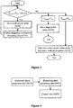
- Figure 2 is a flowchart of a method of determining frequency modulation remaining time according to an embodiment of the present disclosure.
- step S210 the rotational speed ⁇ ( n + 1) of the wind turbine at the next moment T ( n + 1) is predicted based on the rotational speed ⁇ ( n ) of the wind turbine at the current moment T ( n ).
- step S220 it is determined whether the rotational speed ⁇ ( n + 1) satisfies the predetermined condition.
- step S240 a sum of 1 and a difference between a current value of n and an original value of n is determined, to obtain the number m of predetermined time steps that have passed.
- step S250 a product of the number m and the predetermined time step Ts is calculated, as the frequency modulation remaining time.
- the steps S110 and S120 can be executed periodically during the power boost of the primary frequency modulation, to provide the latest prediction data for subsequent steps.
- step S130 the output power is controlled based on the determined frequency modulation remaining time.
- the step of controlling the output power based on the determined frequency modulation remaining time includes stopping boosting the output power before the frequency modulation remaining time falls to a preset value. For example, it may stop the primary frequency modulation, or restore the output power from the frequency modulation power to output power before the primary frequency modulation.
- the preset value can be a time length larger than or equal to zero.
- the step of controlling the output power based on the determined frequency modulation remaining time includes adjusting the frequency modulation power, so that the determined frequency modulation remaining time is as close as possible to remaining frequency modulation time required by the primary frequency modulation.
- the frequency modulation power can be adjusted periodically at a predetermined time interval T in .
- the frequency of adjusting the frequency modulation power can be the sampling frequency of the controller of the wind turbine, such as 50Hz.
- the predetermined time interval T in is 1/50 second.
- Figure 3 is a flowchart of a method of controlling the output power based on the determined frequency modulation remaining time according to an embodiment of the present disclosure.
- step S310 it is determined whether the determined frequency modulation remaining time T remain is smaller than the remaining frequency modulation time T req required by the primary frequency modulation.
- the remaining frequency modulation time T req required by the primary frequency modulation refers to time required to continue output the frequency modulation power to complete the primary frequency modulation.
- step S320 If it is determined that the determined frequency modulation remaining time T remain is smaller than the remaining frequency modulation time T req required by the primary frequency modulation in step S310, a power value smaller than current frequency modulation power is set in step S320.
- step S330 in case that the set power value is the frequency modulation power, the rotational speed of the wind turbine is predicted again, the frequency modulation remaining time is determined again based on the rotational speed predicted again, and then the step 310 is returned to.
- the rotational speed of the wind turbine can be predicted again and the frequency modulation remaining time can be determined again based on steps S110 and S120. During this period, the set power value is taken as the frequency modulation power at the current moment.
- step S310 If it is determined that the determined frequency modulation remaining time is larger than the remaining frequency modulation time required for the primary frequency modulation in step S310, a power value lager than the current frequency modulation power is set in step S340, and the step 330 is returned to.
- the current power value is taken as the frequency modulation power in step S350.
- a reduction ratio of a power value set for the first time, which is smaller than the current frequency modulation power is larger than a reduction ratio of a power value set after the first time, which is also smaller than the current frequency modulation power; and an increase ratio of a power value set for the first time, which is larger than the current frequency modulation power, is larger than an increase ratio of a power value set after the first time, which is also larger than the current frequency modulation power.
- the power value set for the first time, which is smaller than the current frequency modulation power P boost can be expressed as P boost ⁇ (100 % - ⁇ iter ); the power value set after the first time, which is also smaller than the current frequency modulation power can be expressed as P boost ⁇ (100 % - ⁇ iter / 2).
- the power value set for the first time, which is larger than the current frequency modulation power can be expressed as P boost ⁇ (100 % + ⁇ iter ) ;
- the power value set after the first time, which is also larger than the current frequency modulation power can be expressed as P boost ⁇ (100 % + ⁇ iter / 2).
- ⁇ iter is a positive value.
- a power value set for the last time is taken as the frequency modulation power.
- the predetermined time interval T in is smaller than the predetermined time step Ts . In this case, there is no need to predict the frequency modulation remaining time for each adjustment of the frequency modulation power over time, which reduces a computational load.
- Figure 4 is a block diagram of a device for controlling output power in a primary frequency modulation process of a wind turbine according to an embodiment of the present disclosure.
- the device 400 for controlling output power in a primary frequency modulation process of a wind turbine includes a rotational speed prediction unit 410, a remaining time prediction unit 420, and a control unit 430.
- the rotational speed prediction unit 410 is configured to predict a rotational speed of the wind turbine.
- the rotational speed prediction unit 410 is configured to predict a next rotational speed of the wind turbine at a next moment by using a rotational speed of the wind turbine at a current moment and a frequency modulation power at the current moment iteratively.
- the next moment is separated from the current moment by a predetermined time step.
- rotational speeds at moments separated by a predetermined time step are predicted. Two moments corresponding to two adjacent predicted rotational speeds are separated by the predetermined time step. For a situation of predicting rotational speeds of two adjacent moments, the two moments are separated by the predetermined time step.
- T(n + 1) - T(n) is Ts (Ts is the predetermined time step).
- a next rotational speed after the predetermined time step can be predicted based on the rotational speed at the current moment, the aerodynamic mechanical torque at the current moment, the electromagnetic torque of the generator at the current moment related to the frequency modulation power at the current moment, the predetermined time step, and the moment of inertia of the rotor.
- the electromagnetic torque of the generator at the current moment is a ratio of the power of the frequency modulation at the current moment and the rotational speed at the current moment.
- the predicted next rotational speed after the predetermined time step is a sum of the rotational speed at the current moment and a result of weighting a difference between the aerodynamic mechanical torque at the current moment and the electromagnetic torque of the generator at the current moment by a ratio of the predetermined time step and the moment of inertia of the rotor.
- the prediction of the rotational speed can be realized via the above equation (1).
- the remaining time prediction unit 120 is configured to determine frequency modulation remaining time based on the predicted rotational speed.
- the frequency modulation remaining time is time for which the wind turbine is able to continue to output frequency modulation power as the output power used for the primary frequency modulation without affecting a recovery of the wind turbine after the primary frequency modulation.
- the remaining time prediction unit 120 is configured to determine whether the predicted rotational speed satisfies a predetermined condition each time the rotational speed is predicted; determine the number of predetermined time steps that have passed (i.e., the number of times of iterations till the rotational speed has been predicted) when any one of the predicted rotational speeds satisfies the predetermined condition; and calculates a product of the number and the predetermined time step as the frequency modulation remaining time.
- the predetermined condition is that the aerodynamic mechanical torque of the wind turbine determined based on any one of the predicted rotational speeds is larger than a ratio of a lowest output power weighted by a predetermined factor and the any one of the predicted rotational speeds.
- the lowest output power is the minimum output power allowed in a recovery process of the wind turbine after the primary frequency modulation.
- the condition can be expressed as the above inequation (4).
- an example of determining the frequency modulation remaining time illustrated in Figure 2 can be executed by the rotational speed prediction unit 410 in conjunction with the remaining time prediction unit 420.
- the control unit 430 is configured to control the output power based on the determined frequency modulation remaining time.
- control unit 430 is configured to stop boosting the output power before the frequency modulation remaining time falls to a preset value. For example, it may stop the primary frequency modulation, or restore the output power from the frequency modulation power to output power before the primary frequency modulation.
- the preset value can be a time length larger than or equal to zero.
- control unit 430 is configured to adjust the frequency modulation power, so that the determined frequency modulation remaining time is as close as possible to remaining frequency modulation time required by the primary frequency modulation.
- the frequency modulation power can be adjusted periodically at a predetermined time interval T in .
- the control unit 430 can adjust the frequency modulation power based on a way illustrated in Figure 3 .
- a control system in a wind turbine includes a processor and a memory.
- the memory is configured to store computer readable codes, instructions, or programs.
- the method for controlling output power in a primary frequency modulation process of a wind turbine according to the embodiments of the present disclosure is executed when the computer readable codes, instructions, or programs are executed by the processor.
- the units of the device can be implemented as hardware modules and/or software modules. Those skilled in the art can implement the units based on the processes executed by the units, for example, by using a field programmable gate array (FPGA) or an application-specific integrated circuit (ASIC).
- FPGA field programmable gate array
- ASIC application-specific integrated circuit
- the method according to the embodiments of the present disclosure can be implemented as computer codes in a computer readable storage medium.
- Those skilled in the art can implement the computer codes according to the description of the above method.
- the above method of the present disclosure can be implemented when the computer codes are executed in a computer.
Landscapes
- Engineering & Computer Science (AREA)
- Life Sciences & Earth Sciences (AREA)
- Sustainable Development (AREA)
- Sustainable Energy (AREA)
- Chemical & Material Sciences (AREA)
- Combustion & Propulsion (AREA)
- Mechanical Engineering (AREA)
- General Engineering & Computer Science (AREA)
- Wind Motors (AREA)
- Control Of Eletrric Generators (AREA)
Description
- The present disclosure relates to the field of wind power generation, particularly to a method and a device for controlling output power in a primary frequency modulation process of a wind turbine.
- Baccino Francesco ET AL discloses a model-based control technique to provide the contribution of wind power generators to primary frequency regulation in electric power systems. Each turbine can react to grid disturbances in a different way, which depends on wind speed as seen by the wind turbine itself and by its dynamical conditions. Real wind data and a large WF connected to the grid in a dedicated simulation environment have been used to test the effectiveness of the proposed control strategy. See Baccino Francesco ET AL, titled "An Optimal Model-Based Control Technique to Improve Wind Farm Participation to Frequency Regulation", IEEE TRANSACTIONS ON SUSTAINABLE ENERGY, IEEE, USA, vol.6, no.3, 1 July 2015, pages 993-1003.
- As a clean renewable resource, wind energy is being paid more and more attention. An installed capacity of the wind turbine is also increasing. The wind turbine can convert kinetic energy of wind into mechanical kinetic energy, and then convert the mechanical energy into electrical energy. In the primary frequency modulation process of the wind turbine, the output power of the wind turbine needs to be boosted for a specified duration. After the primary frequency modulation, the wind turbine needs to recover rotor's kinetic energy which is released during the primary frequency modulation to an original level, and store the rotor's kinetic energy again, which result in a decline in power. If the wind speed suddenly drops during the primary frequency modulation, it means more kinetic energy of the rotor needs to be released to boost the output power, to ensure the specified duration, which may result in a sharp decline of the output power of the wind turbine during a recovery period after the primary frequency modulation.
- A method for controlling output power in a primary frequency modulation process of a wind turbine is provided according to an aspect of the present disclosure. The method includes predicting a rotational speed of the wind turbine; determining frequency modulation remaining time based on the predicted rotational speed, the frequency modulation remaining time being time for which the wind turbine is able to continue to output frequency modulation power as the output power used for the primary frequency modulation without affecting a recovery of the wind turbine after the primary frequency modulation; and controlling the output power based on the determined frequency modulation remaining time.
- A device for controlling output power in a primary frequency modulation process of a wind turbine is provided according to an aspect of the present disclosure. The device includes a rotational speed prediction unit configured to predict a rotational speed of the wind turbine; a remaining time prediction unit configured to determine frequency modulation remaining time based on the predicted rotational speed, the frequency modulation remaining time being time for which the wind turbine is able to continue to output frequency modulation power as the output power used for the primary frequency modulation without affecting recovery of the wind turbine after the primary frequency modulation; and a control unit configured to control the output power based on the determined frequency modulation remaining time.
- A control system in a wind turbine is provided according to an aspect of the present disclosure. The control system includes a processor and a memory storing a computer program that, when executed by the processor, causes the method described above to be performed.
- A computer readable storage medium storing a computer program is provided according to an aspect of the present disclosure. The computer program, when executed by the processor, causes the method described above to be performed.
- The method and device for controlling output power in a primary frequency modulation process of a wind turbine according to embodiments of the present disclosure dynamically adjust the output power of the primary frequency modulation, such that the output power of the wind turbine can be boosted during the whole primary frequency modulation process. At the same time, a problem of excessive decline of the output power caused by restoring the kinetic energy of the rotor during the recovery period of the wind turbine after completing the primary frequency modulation is avoid.
- Part of other aspects and/or advantages will be described hereinafter, the other aspects and/or advantages will be clear according to the description, or can be known by implementations of the present disclosure.
- The above and other objects, characteristics and advantages will be more clear according to following detailed descriptions in conjunction with drawings, wherein:
-
Figure 1 is a flowchart of a method for controlling output power in a primary frequency modulation process of a wind turbine according to an embodiment of the present disclosure; -
Figure 2 is a flowchart of a method of determining frequency modulation remaining time according to an embodiment of the present disclosure; -
Figure 3 is a flowchart of a method of controlling the output power based on the determined frequency modulation remaining time according to an embodiment of the present disclosure; and -
Figure 4 is a block diagram of a device for controlling output power in a primary frequency modulation process of a wind turbine according to an embodiment of the present disclosure. - Exemplary embodiments of the present disclosure are fully described hereinafter in conjunction with drawings, and some of the exemplary embodiments are illustrated in the drawings.
- In a frequency modulation process of a wind turbine, when there is a need to boost output power, the frequency modulation power for the primary frequency modulation is determined as the output power. When the wind turbine outputs the frequency modulation power, the frequency modulation power can be controlled by the method of the present disclosure.
-
Figure 1 is a flowchart of a method for controlling output power in a primary frequency modulation process of a wind turbine according to an embodiment of the present disclosure. - In step S110, a rotational speed of the wind turbine is predicted.
- In an embodiment of the present disclosure, a next rotational speed of the wind turbine at a next moment is predicted by using a rotational speed of the wind turbine at a current moment and a frequency modulation power at the current moment iteratively. The next moment is separated from the current moment by a predetermined time step. That is to say, rotational speeds at moments separated by a predetermined time step are predicted. Two moments corresponding to two adjacent predicted rotational speeds are separated by the predetermined time step. For a situation of predicting rotational speeds of two adjacent moments, the two moments are separated by the predetermined time step. For example, in two adjacent predictions of rotational speeds, the rotational speed ω(n) at the current moment T(n) and the rotational speed ω(n + 1) at the next moment T(n + 1) are predicted. T(n + 1) - T(n) is Ts (Ts is the predetermined time step). Therefore, the predicted rotational speed can be used to continue predicting its next rotational speed.
- In an embodiment of the present disclosure, a next rotational speed after the predetermined time step can be predicted based on the rotational speed at the current moment, the aerodynamic mechanical torque at the current moment, the electromagnetic torque of the generator at the current moment related to the frequency modulation power at the current moment, the predetermined time step, and the moment of inertia of the rotor. The electromagnetic torque of the generator at the current moment is a ratio of the power of the frequency modulation at the current moment and the rotational speed at the current moment. The predicted next rotational speed after the predetermined time step is a sum of the rotational speed at the current moment and a result of weighting a difference between the aerodynamic mechanical torque at the current moment and the electromagnetic torque of the generator at the current moment by a predetermined weighting value. The predetermined weighting value is a ratio of the predetermined time step and the moment of inertia of the rotor. The prediction of the rotational speed can be realized via the following equation (1):

- In an embodiment, the aerodynamic mechanical torque at the current moment τaero [n] and the electromagnetic torque of the generator at the current moment τgen [n] can be determined based on the rotational speed at the current moment ω(n). For example, it may be determined based on following equations (2) and (3):


- In an embodiment, the tip speed ratio at the current moment and the pitch angle at the current moment can be determined based on various existing schemes. For example, they can be determined based on the rotational speed at the current moment ω(n), which is not repeated herein. It can be understood that equations (2) and (3) are just exemplary. The aerodynamic mechanical torque at the current moment τaero [n] and the electromagnetic torque of the generator at the current moment τgen [n] can be determined based on other schemes.
- In an embodiment, the rotational speed at the current moment, the aerodynamic mechanical torque of the wind turbine at the current moment, and the generator electromagnetic torque of the wind turbine at the current moment used for predicting the rotational speed after a first predetermined time step (here, n=1) are measured values;
- the rotational speed at the current moment, the aerodynamic mechanical torque at the current moment, and the generator electromagnetic torque at the current moment used for predicting the rotational speed after a nth predetermined time step (here, n is a natural number greater than 1) are obtained based on the predicted rotational speed after a n-1th predetermined time step.
- In step S120, frequency modulation remaining time is determined based on the predicted rotational speed. The frequency modulation remaining time is time for which the wind turbine is able to continue to output frequency modulation power as the output power used for the primary frequency modulation without affecting the recovery of the wind turbine after the primary frequency modulation.
- Specifically, it is determined whether the predicted rotational speed satisfies a predetermined condition each time the rotational speed is predicted; the number of predetermined time steps that have passed (i.e., the number of times of iterations till the rotational speed has been predicted) is determined when any one of the predicted rotational speeds satisfies the predetermined condition; and a product of the number and the predetermined time step is calculated as the frequency modulation remaining time.
- In an embodiment, the predetermined condition is that the aerodynamic mechanical torque of the wind turbine determined based on any one of the predicted rotational speeds is larger than a ratio of a lowest output power weighted by a predetermined factor and the any one of the predicted rotational speeds. The lowest output power is the minimum output power allowed in a recovery process of the wind turbine after the primary frequency modulation. For example, the condition can be expressed as the following inequation (4):

where τaero [n + 1] is the aerodynamic mechanical torque of the wind turbine determined based on the predicted rotational speed, ω[n + 1] is the rotational speed, γ is the predetermined factor, Prec is the lowest output power. - A detailed flowchart of an example of determining the frequency modulation remaining time via steps S110 and S120 will be described hereinafter based on
Figure 2 . -
Figure 2 is a flowchart of a method of determining frequency modulation remaining time according to an embodiment of the present disclosure. - In step S210, the rotational speed ω(n + 1) of the wind turbine at the next moment T(n + 1) is predicted based on the rotational speed ω(n) of the wind turbine at the current moment T(n).
- In step S220, it is determined whether the rotational speed ω(n + 1) satisfies the predetermined condition.
- When it is determined the rotational speed ω(n + 1) does not satisfy the predetermined condition, in step S230, make n=n+1, and return to step S210, to predict the rotational speed at the next moment by using the latest predicted rotational speed.
- When it is determined the rotational speed ω(n + 1) satisfy the predetermined condition, in step S240, a sum of 1 and a difference between a current value of n and an original value of n is determined, to obtain the number m of predetermined time steps that have passed.
- In step S250, a product of the number m and the predetermined time step Ts is calculated, as the frequency modulation remaining time.
- The steps S110 and S120 can be executed periodically during the power boost of the primary frequency modulation, to provide the latest prediction data for subsequent steps.
- In step S130, the output power is controlled based on the determined frequency modulation remaining time.
- In an embodiment, the step of controlling the output power based on the determined frequency modulation remaining time includes stopping boosting the output power before the frequency modulation remaining time falls to a preset value. For example, it may stop the primary frequency modulation, or restore the output power from the frequency modulation power to output power before the primary frequency modulation. Herein, the preset value can be a time length larger than or equal to zero.
- In an embodiment, the step of controlling the output power based on the determined frequency modulation remaining time includes adjusting the frequency modulation power, so that the determined frequency modulation remaining time is as close as possible to remaining frequency modulation time required by the primary frequency modulation. The frequency modulation power can be adjusted periodically at a predetermined time interval Tin . In an embodiment, the frequency of adjusting the frequency modulation power can be the sampling frequency of the controller of the wind turbine, such as 50Hz. Here, the predetermined time interval Tin is 1/50 second.
- Reference is made to
Figure 3 , which is a flowchart of a method of controlling the output power based on the determined frequency modulation remaining time according to an embodiment of the present disclosure. - As shown in
Figure 3 , in step S310, it is determined whether the determined frequency modulation remaining time Tremain is smaller than the remaining frequency modulation time Treq required by the primary frequency modulation. - The remaining frequency modulation time Treq required by the primary frequency modulation refers to time required to continue output the frequency modulation power to complete the primary frequency modulation.
- If it is determined that the determined frequency modulation remaining time Tremain is smaller than the remaining frequency modulation time Treq required by the primary frequency modulation in step S310, a power value smaller than current frequency modulation power is set in step S320.
- In step S330, in case that the set power value is the frequency modulation power, the rotational speed of the wind turbine is predicted again, the frequency modulation remaining time is determined again based on the rotational speed predicted again, and then the
step 310 is returned to. - The rotational speed of the wind turbine can be predicted again and the frequency modulation remaining time can be determined again based on steps S110 and S120. During this period, the set power value is taken as the frequency modulation power at the current moment.
- If it is determined that the determined frequency modulation remaining time is larger than the remaining frequency modulation time required for the primary frequency modulation in step S310, a power value lager than the current frequency modulation power is set in step S340, and the step 330 is returned to.
- If it is determined that the determined frequency modulation remaining time is equal to the remaining frequency modulation time required for the primary frequency modulation in step S310, the current power value is taken as the frequency modulation power in step S350.
- In an embodiment, in the method shown in
Figure 2 , a reduction ratio of a power value set for the first time, which is smaller than the current frequency modulation power, is larger than a reduction ratio of a power value set after the first time, which is also smaller than the current frequency modulation power; and an increase ratio of a power value set for the first time, which is larger than the current frequency modulation power, is larger than an increase ratio of a power value set after the first time, which is also larger than the current frequency modulation power. - For example, the power value set for the first time, which is smaller than the current frequency modulation power Pboost can be expressed as Pboost × (100 % - Δ iter ); the power value set after the first time, which is also smaller than the current frequency modulation power can be expressed as Pboost × (100 % - Δ iter / 2). The power value set for the first time, which is larger than the current frequency modulation power can be expressed as Pboost × (100 % + Δ iter ) ; the power value set after the first time, which is also larger than the current frequency modulation power can be expressed as Pboost × (100 % + Δ iter / 2). Δ iter is a positive value.
- In addition, when the frequency modulation remaining time determined at end of the predetermined time interval is not equal to the remaining frequency modulation time required by the primary frequency modulation, a power value set for the last time is taken as the frequency modulation power.
- In an embodiment, in the present disclosure, the predetermined time interval Tin is smaller than the predetermined time step Ts . In this case, there is no need to predict the frequency modulation remaining time for each adjustment of the frequency modulation power over time, which reduces a computational load.
-
Figure 4 is a block diagram of a device for controlling output power in a primary frequency modulation process of a wind turbine according to an embodiment of the present disclosure. - As shown in
Figure 4 , the device 400 for controlling output power in a primary frequency modulation process of a wind turbine according to the embodiment of the present disclosure includes a rotational speed prediction unit 410, a remaining time prediction unit 420, and a control unit 430. - The rotational speed prediction unit 410 is configured to predict a rotational speed of the wind turbine. In an embodiment of the present disclosure, the rotational speed prediction unit 410 is configured to predict a next rotational speed of the wind turbine at a next moment by using a rotational speed of the wind turbine at a current moment and a frequency modulation power at the current moment iteratively. The next moment is separated from the current moment by a predetermined time step. In an embodiment, rotational speeds at moments separated by a predetermined time step are predicted. Two moments corresponding to two adjacent predicted rotational speeds are separated by the predetermined time step. For a situation of predicting rotational speeds of two adjacent moments, the two moments are separated by the predetermined time step. For example, in two adjacent predictions of rotational speeds, the rotational speed ω(n) at the current moment T(n) and the rotational speed ω(n + 1) at the next moment T(n + 1) are predicted. T(n + 1) - T(n) is Ts (Ts is the predetermined time step).
- In an embodiment of the present disclosure, a next rotational speed after the predetermined time step can be predicted based on the rotational speed at the current moment, the aerodynamic mechanical torque at the current moment, the electromagnetic torque of the generator at the current moment related to the frequency modulation power at the current moment, the predetermined time step, and the moment of inertia of the rotor. The electromagnetic torque of the generator at the current moment is a ratio of the power of the frequency modulation at the current moment and the rotational speed at the current moment. The predicted next rotational speed after the predetermined time step is a sum of the rotational speed at the current moment and a result of weighting a difference between the aerodynamic mechanical torque at the current moment and the electromagnetic torque of the generator at the current moment by a ratio of the predetermined time step and the moment of inertia of the rotor. The prediction of the rotational speed can be realized via the above equation (1).
- The remaining time prediction unit 120 is configured to determine frequency modulation remaining time based on the predicted rotational speed. The frequency modulation remaining time is time for which the wind turbine is able to continue to output frequency modulation power as the output power used for the primary frequency modulation without affecting a recovery of the wind turbine after the primary frequency modulation.
- In an embodiment, the remaining time prediction unit 120 is configured to determine whether the predicted rotational speed satisfies a predetermined condition each time the rotational speed is predicted; determine the number of predetermined time steps that have passed (i.e., the number of times of iterations till the rotational speed has been predicted) when any one of the predicted rotational speeds satisfies the predetermined condition; and calculates a product of the number and the predetermined time step as the frequency modulation remaining time.
- In an embodiment, the predetermined condition is that the aerodynamic mechanical torque of the wind turbine determined based on any one of the predicted rotational speeds is larger than a ratio of a lowest output power weighted by a predetermined factor and the any one of the predicted rotational speeds. The lowest output power is the minimum output power allowed in a recovery process of the wind turbine after the primary frequency modulation. For example, the condition can be expressed as the above inequation (4).
- In an embodiment, an example of determining the frequency modulation remaining time illustrated in
Figure 2 can be executed by the rotational speed prediction unit 410 in conjunction with the remaining time prediction unit 420. - The control unit 430 is configured to control the output power based on the determined frequency modulation remaining time.
- In an embodiment, the control unit 430 is configured to stop boosting the output power before the frequency modulation remaining time falls to a preset value. For example, it may stop the primary frequency modulation, or restore the output power from the frequency modulation power to output power before the primary frequency modulation. Herein, the preset value can be a time length larger than or equal to zero.
- In an embodiment, the control unit 430 is configured to adjust the frequency modulation power, so that the determined frequency modulation remaining time is as close as possible to remaining frequency modulation time required by the primary frequency modulation. The frequency modulation power can be adjusted periodically at a predetermined time interval Tin . For example, the control unit 430 can adjust the frequency modulation power based on a way illustrated in
Figure 3 . - A control system in a wind turbine is provided according to an embodiment of the present disclosure. The control system includes a processor and a memory. The memory is configured to store computer readable codes, instructions, or programs. The method for controlling output power in a primary frequency modulation process of a wind turbine according to the embodiments of the present disclosure is executed when the computer readable codes, instructions, or programs are executed by the processor.
- In addition, it should be understood that the units of the device according to the embodiments of the present disclosure can be implemented as hardware modules and/or software modules. Those skilled in the art can implement the units based on the processes executed by the units, for example, by using a field programmable gate array (FPGA) or an application-specific integrated circuit (ASIC).
- In addition, the method according to the embodiments of the present disclosure can be implemented as computer codes in a computer readable storage medium. Those skilled in the art can implement the computer codes according to the description of the above method. The above method of the present disclosure can be implemented when the computer codes are executed in a computer.
- Although the present disclosure is shown and described specifically with reference to its exemplary embodiments, it should be understood by those skilled in the art that various changes in form and detail may be made to the present disclosure without departing from the principle and scope of the present disclosure as defined by the appended claims.
Claims (15)
- A method for controlling output power in a primary frequency modulation process of a wind turbine, comprising:predicting a rotational speed of the wind turbine;characterised bydetermining frequency modulation remaining time based on the predicted rotational speed, wherein, the frequency modulation remaining time is time for which the wind turbine is able to continue to output frequency modulation power as the output power used for the primary frequency modulation without affecting recovery of the wind turbine after the primary frequency modulation; andcontrolling the output power based on the determined frequency modulation remaining time.
- The method according to claim 1, wherein controlling the output power based on the determined frequency modulation remaining time comprises: stopping boosting the output power before the frequency modulation remaining time falls to a preset value.
- The method according to claim 1, wherein predicting the rotational speed of the wind turbine comprises:predicting a rotational speed of the wind turbine at a next moment by using a rotational speed of the wind turbine at a current moment and a frequency modulation power at the current moment iteratively, wherein the next moment is separated from the current moment by a predetermined time step, andwherein determining the frequency modulation remaining time comprises:determining whether the predicted rotational speed satisfies a predetermined condition each time the rotational speed is predicted;determining a number of predetermined time steps that have passed when one of the predicted rotational speeds satisfies the predetermined condition; andcalculating a product of the number and the predetermined time step as the frequency modulation remaining time.
- The method according to claim 3, wherein, a rotational speed after the predetermined time step is predicted based on the rotational speed at the current moment, an aerodynamic mechanical torque at the current moment, a generator electromagnetic torque at the current moment related to the frequency modulation power at the current moment, the predetermined time step, and a rotor moment of inertia;
wherein, the rotational speed at the current moment, the aerodynamic mechanical torque of the wind turbine at the current moment, and the generator electromagnetic torque of the wind turbine at the current moment used for predicting the rotational speed after a first predetermined time step are measured values;
wherein, the rotational speed at the current moment, the aerodynamic mechanical torque at the current moment, and the generator electromagnetic torque at the current moment used for predicting the rotational speed after a nth predetermined time step are obtained based on a predicted rotational speed after a n-1th predetermined time step, and, n is a natural number greater than 1; and
wherein, the predicted rotational speed after the predetermined time step is a sum of the rotational speed at the current moment and a result of weighting a difference between the aerodynamic mechanical torque at the current moment and the generator electromagnetic torque at the current moment by a predetermined weighting value, and the predetermined weighting value is a ratio of the predetermined time step and the rotor moment of inertia. - The method according to claim 3, wherein, the predetermined condition is that an aerodynamic mechanical torque of the wind turbine determined based on the one of the predicted rotational speeds is larger than a ratio of a lowest output power weighted by a predetermined factor and the one of the predicted rotational speeds,
wherein, the lowest output power is a minimum output power allowed in a recovery process of the wind turbine after the primary frequency modulation. - The method according to claim 3, further comprising adjusting the frequency modulation power periodically at a predetermined time interval,
wherein, adjusting the frequency modulation power comprises:(A1) determining whether the determined frequency modulation remaining time is smaller than remaining frequency modulation time required by the primary frequency modulation;(A2) setting a power value smaller than current frequency modulation power if the determined frequency modulation remaining time is smaller than the remaining frequency modulation time required by the primary frequency modulation;(A3) in case that the set power value is the frequency modulation power, predicting the rotational speed of the wind turbine again, determining the frequency modulation remaining time again based on the rotational speed predicted again, and returning to the step (A1);(A4) setting a power value lager than the current frequency modulation power if the determined frequency modulation remaining time is larger than the remaining frequency modulation time required by the primary frequency modulation, and returning to the step (A3); and(A5) taking a current power value as the frequency modulation power if the determined frequency modulation remaining time is equal to the remaining frequency modulation time required by the primary frequency modulation. - The method according to claim 6, wherein, a reduction ratio of a power value set for the first time, which is smaller than the current frequency modulation power, is larger than a reduction ratio of a power value set after the first time, which is also smaller than the current frequency modulation power; and an increase ratio of a power value set for the first time, which is larger than the current frequency modulation power, is larger than an increase ratio of a power value set after the first time, which is also larger than the current frequency modulation power,
wherein, a power value set for the last time is taken as the frequency modulation power when the frequency modulation remaining time determined at end of the predetermined time interval is not equal to the remaining frequency modulation time required by the primary frequency modulation; and
wherein, the predetermined time interval is smaller than the predetermined time step. - A device for controlling output power in a primary frequency modulation process of a wind turbine, comprising:a rotational speed prediction unit configured to predict a rotational speed of the wind turbine;characterised bya remaining time prediction unit configured to determine frequency modulation remaining time based on the predicted rotational speed, wherein, the frequency modulation remaining time is time for which the wind turbine is able to continue to output frequency modulation power as the output power used for the primary frequency modulation without affecting recovery of the wind turbine after the primary frequency modulation; anda control unit configured to control the output power based on the determined frequency modulation remaining time.
- The device according to claim 8, wherein the control unit is configured to stop boosting the output power before the frequency modulation remaining time falls to a preset value.
- The device according to claim 8, wherein the rotational speed prediction unit is configured to predict a rotational speed of the wind turbine at a next moment by using a rotational speed of the wind turbine at a current moment and a frequency modulation power at the current moment iteratively, and the next moment is separated from the current moment by a predetermined time step; and
the remaining time prediction unit is configured to determine whether the predicted rotational speed satisfies a predetermined condition each time the rotational speed is predicted, determine a number of predetermined time steps that have passed when one of the predicted rotational speeds satisfies the predetermined condition, and calculate a product of the number and the predetermined time step as the frequency modulation remaining time. - The device according to claim 10, wherein,
the rotational speed prediction unit is configured to predict a next rotational speed after the predetermined time step based on the rotational speed at the current moment, an aerodynamic mechanical torque at the current moment, a generator electromagnetic torque at the current moment related to the frequency modulation power at the current moment, the predetermined time step, and a rotor moment of inertia;
wherein, the rotational speed at the current moment, the aerodynamic mechanical torque of the wind turbine at the current moment, and the generator electromagnetic torque of the wind turbine at the current moment used for predicting the rotational speed after a first predetermined time step are measured values;
wherein, the rotational speed at the current moment, the aerodynamic mechanical torque at the current moment, and the generator electromagnetic torque at the current moment used for predicting the rotational speed after a nth predetermined time step are obtained based on a predicted rotational speed after a n-1th predetermined time step, and, n is a natural number greater than 1; and
wherein, the predicted rotational speed after the predetermined time step is a sum of the rotational speed at the current moment and a result of weighting a difference between the aerodynamic mechanical torque at the current moment and the generator electromagnetic torque at the current moment by a predetermined weighting value, and the predetermined weighting value is a ratio of the predetermined time step and the rotor moment of inertia. - The device according to claim 10, wherein,
the predetermined condition is that an aerodynamic mechanical torque of the wind turbine determined based on the one of the predicted rotational speeds is larger than a ratio of a lowest output power weighted by a predetermined factor and the one of the predicted rotational speeds,
wherein, the lowest output power is a minimum output power allowed in a recovery process of the wind turbine after the primary frequency modulation. - The device according to claim 10, wherein the control unit is configured to adjust the frequency modulation power periodically at a predetermined time interval by:(A1) determining whether the determined frequency modulation remaining time is smaller than remaining frequency modulation time required by the primary frequency modulation;(A2) setting a power value smaller than current frequency modulation power if the determined frequency modulation remaining time is smaller than the remaining frequency modulation time required by the primary frequency modulation;(A3) in case that the set power value is the frequency modulation power, predicting the rotational speed of the wind turbine again, determining the frequency modulation remaining time again based on the rotational speed predicted again, and returning to the step (A1);(A4) setting a power value lager than the current frequency modulation power if the determined frequency modulation remaining time is larger than the remaining frequency modulation time required by the primary frequency modulation, and returning to the step (A3); and(A5) taking a current power value as the frequency modulation power if the determined frequency modulation remaining time is equal to the remaining frequency modulation time required by the primary frequency modulation.
- The device according to claim 13, wherein, a reduction ratio of a power value set for the first time, which is smaller than the current frequency modulation power, is larger than a reduction ratio of a power value set after the first time, which is also smaller than the current frequency modulation power; and an increase ratio of a power value set for the first time, which is larger than the current frequency modulation power, is larger than an increase ratio of a power value set after the first time, which is also larger than the current frequency modulation power;
wherein, the control unit is configured to take a power value set for the last time as the frequency modulation power when the frequency modulation remaining time determined at end of the predetermined time interval is not equal to the remaining frequency modulation time required by the primary frequency modulation, and
wherein, the predetermined time interval is smaller than the predetermined time step. - A control system in a wind turbine, wherein, the control system comprises:a processor; anda memory storing a computer program that, when executed by the processor, causes the method according to any one of claims 1 to 7 to be executed.
Applications Claiming Priority (2)
| Application Number | Priority Date | Filing Date | Title |
|---|---|---|---|
| CN201710584766.2A CN107152377B (en) | 2017-07-18 | 2017-07-18 | Method and device for controlling output power of wind generating set |
| PCT/CN2017/118981 WO2019015255A1 (en) | 2017-07-18 | 2017-12-27 | Method and device for controlling output power of wind generating set |
Publications (3)
| Publication Number | Publication Date |
|---|---|
| EP3456958A1 EP3456958A1 (en) | 2019-03-20 |
| EP3456958A4 EP3456958A4 (en) | 2019-05-08 |
| EP3456958B1 true EP3456958B1 (en) | 2021-06-02 |
Family
ID=59797126
Family Applications (1)
| Application Number | Title | Priority Date | Filing Date |
|---|---|---|---|
| EP17900282.9A Active EP3456958B1 (en) | 2017-07-18 | 2017-12-27 | Method and device for controlling output power of wind generating set |
Country Status (6)
| Country | Link |
|---|---|
| US (2) | US11105315B2 (en) |
| EP (1) | EP3456958B1 (en) |
| CN (1) | CN107152377B (en) |
| AU (1) | AU2017404568C1 (en) |
| ES (1) | ES2877146T3 (en) |
| WO (1) | WO2019015255A1 (en) |
Families Citing this family (12)
| Publication number | Priority date | Publication date | Assignee | Title |
|---|---|---|---|---|
| CN107152377B (en) | 2017-07-18 | 2019-04-09 | 北京金风科创风电设备有限公司 | Method and device for controlling output power of wind generating set |
| CN110098622B (en) * | 2018-01-31 | 2021-04-13 | 北京金风科创风电设备有限公司 | Primary frequency modulation method and equipment for wind turbines |
| CN111262256B (en) * | 2018-11-30 | 2024-06-14 | 北京金风科创风电设备有限公司 | Primary frequency modulation control method and device for wind turbine generator set |
| CN109667728B (en) * | 2018-12-21 | 2020-09-08 | 北京金风科创风电设备有限公司 | Fault detection method and device for wind turbine speed sensor |
| EP3712426A1 (en) * | 2019-03-22 | 2020-09-23 | Siemens Gamesa Renewable Energy A/S | Estimating of inertial response power of a wind turbine |
| CN112696318B (en) * | 2019-10-22 | 2023-06-16 | 北京金风科创风电设备有限公司 | Control method and device for wind generating set |
| CN111091236B (en) * | 2019-11-27 | 2023-06-20 | 长春吉电能源科技有限公司 | Multi-classification deep learning short-term wind power prediction method classified according to pitch angles |
| CN114188991B (en) * | 2021-11-03 | 2024-03-12 | 国网吉林省电力有限公司 | Wind farm primary frequency modulation model identification method, device, electronic equipment and storage medium |
| CN114033617B (en) * | 2021-12-16 | 2022-08-09 | 金麒麟新能源股份有限公司 | Controllable wind power generation method and system with control parameters adjusted in self-adaptive mode |
| CN115102193B (en) * | 2022-08-04 | 2023-03-21 | 东南大学溧阳研究院 | System frequency secondary falling event prediction method considering wind power participation frequency modulation |
| CN115492718B (en) * | 2022-08-26 | 2024-11-08 | 重庆海装风电工程技术有限公司 | Active power control method, system, equipment and medium for primary frequency modulation |
| CN117738844B (en) * | 2024-02-20 | 2024-04-30 | 威海亨策新能源科技有限公司 | Agricultural new energy wind power generation control system and control method |
Family Cites Families (20)
| Publication number | Priority date | Publication date | Assignee | Title |
|---|---|---|---|---|
| US5172784A (en) * | 1991-04-19 | 1992-12-22 | Varela Jr Arthur A | Hybrid electric propulsion system |
| US6703718B2 (en) * | 2001-10-12 | 2004-03-09 | David Gregory Calley | Wind turbine controller |
| CN102242689B (en) * | 2011-06-24 | 2013-01-02 | 南京理工大学 | Maximum power point (MPP) tracked and controlled improved mountain climbing algorithm based on wind power generation |
| EP2557311A1 (en) * | 2011-08-12 | 2013-02-13 | kk-electronic a/s | A method for controlling a wind power park and a wind power park controlled by such method |
| JP5364842B1 (en) | 2011-11-30 | 2013-12-11 | 三菱重工業株式会社 | Regenerative energy power generator and control method thereof |
| US8598725B1 (en) * | 2012-06-11 | 2013-12-03 | United Technologies Corporation | Utilizing flux controllable PM electric machines for wind turbine applications |
| EP2711543B1 (en) | 2012-09-21 | 2016-08-17 | Siemens Aktiengesellschaft | Operating a wind turbine and a wind farm in different grid strength |
| GB201402627D0 (en) * | 2014-02-14 | 2014-04-02 | New Dawn Innovations Ltd | Digital radio receiver system |
| CN103867387B (en) | 2014-03-28 | 2016-07-06 | 中科恒源科技股份有限公司 | Based on the method that the maximal power tracing of wind-power electricity generation controls |
| KR101450147B1 (en) * | 2014-08-05 | 2014-10-13 | 전북대학교산학협력단 | Inertial control method of wind turbines |
| JP6309911B2 (en) | 2015-03-30 | 2018-04-11 | 三菱重工業株式会社 | Fatigue evaluation system, wind turbine generator including the same, and fatigue assessment method for wind turbine generator |
| CN105045229B (en) * | 2015-06-26 | 2017-11-24 | 国网山东省电力公司电力科学研究院 | Fired power generating unit primary frequency modulation optimal control method and device based on time bias |
| CN105134485B (en) * | 2015-08-18 | 2017-10-27 | 山东大学 | A kind of double-fed Wind turbine inertia frequency modulation active rotating speed Protection control system and method |
| EP3359811B1 (en) * | 2015-10-09 | 2020-09-23 | Vestas Wind Systems A/S | Power boost of a wind turbine using model predictive control |
| US11204388B2 (en) * | 2016-05-09 | 2021-12-21 | Panasonic Intellectual Property Management Co., Ltd. | Power generation equipment monitoring system, power generation equipment monitoring method and program |
| CN106100476A (en) * | 2016-06-15 | 2016-11-09 | 常州工学院 | Wind-power electricity generation output frequency modulation system |
| CN106528912A (en) * | 2016-09-19 | 2017-03-22 | 国网浙江省电力公司经济技术研究院 | Method for estimating frequency regulation capacity of wind power plant |
| CN106286128B (en) * | 2016-09-21 | 2019-03-26 | 华北电力大学 | A system frequency control method and device for a load-shedding variable-speed wind turbine |
| CN106532746B (en) * | 2016-12-27 | 2019-03-05 | 北京四方继保自动化股份有限公司 | A control system and realization method of wind farm participating in primary frequency regulation |
| CN107152377B (en) | 2017-07-18 | 2019-04-09 | 北京金风科创风电设备有限公司 | Method and device for controlling output power of wind generating set |
-
2017
- 2017-07-18 CN CN201710584766.2A patent/CN107152377B/en active Active
- 2017-12-27 AU AU2017404568A patent/AU2017404568C1/en active Active
- 2017-12-27 WO PCT/CN2017/118981 patent/WO2019015255A1/en not_active Ceased
- 2017-12-27 US US16/085,559 patent/US11105315B2/en active Active
- 2017-12-27 EP EP17900282.9A patent/EP3456958B1/en active Active
- 2017-12-27 ES ES17900282T patent/ES2877146T3/en active Active
-
2021
- 2021-08-30 US US17/460,845 patent/US11867153B2/en active Active
Also Published As
| Publication number | Publication date |
|---|---|
| AU2017404568A1 (en) | 2019-02-07 |
| WO2019015255A1 (en) | 2019-01-24 |
| ES2877146T3 (en) | 2021-11-16 |
| US20210388813A1 (en) | 2021-12-16 |
| AU2017404568B2 (en) | 2019-09-12 |
| US20210180563A1 (en) | 2021-06-17 |
| US11867153B2 (en) | 2024-01-09 |
| EP3456958A1 (en) | 2019-03-20 |
| CN107152377A (en) | 2017-09-12 |
| AU2017404568C1 (en) | 2020-02-13 |
| US11105315B2 (en) | 2021-08-31 |
| EP3456958A4 (en) | 2019-05-08 |
| CN107152377B (en) | 2019-04-09 |
Similar Documents
| Publication | Publication Date | Title |
|---|---|---|
| US11867153B2 (en) | Method and device for controlling output power of a wind turbine | |
| EP2818693A1 (en) | Method of controlling inertia in wind farm | |
| CN108350862B (en) | Electricity enhancement of wind turbines using model predictive control | |
| JP5664889B1 (en) | Inertia control method of wind power generator based on time-varying droop | |
| EP3263890B1 (en) | Methods and systems for feedforward control of wind turbines | |
| CN109416523B (en) | Controlling a wind turbine during a low voltage grid event using MPC | |
| Lamsal et al. | Kalman filter approach for dispatching and attenuating the power fluctuation of wind and photovoltaic power generating systems | |
| CN107154647B (en) | Power derating method and controller of photovoltaic power generation system | |
| JP4347030B2 (en) | Wind power generation output prediction method | |
| JP2014140281A (en) | Control device, method, and program, and natural energy power generation device comprising the same | |
| CN108028543A (en) | Power Plant Ramp Rate Control | |
| EP2541052B1 (en) | Controlling a wind turbine using a neural network function | |
| Singaravel et al. | Studies on battery storage requirement of PV fed wind-driven induction generators | |
| JP2017118722A (en) | Power supply system, control apparatus for power supply system, and program | |
| KR101551219B1 (en) | Control apparatus for wind power plant and control method for wind power plant | |
| Aleksandr et al. | MPPT algorithms for wind turbines: review and comparison | |
| EP2980403B1 (en) | Method and system for run-time wind farm | |
| US11808249B2 (en) | Reaction to an overspeed event | |
| US11784504B2 (en) | Method for determining parameters of a simplified model of an energy storage system, control method using such a model and associated device | |
| CN108150352B (en) | Method and device for controlling operation of wind generating set | |
| CN113027674B (en) | Control method and device of wind generating set | |
| Nguyen et al. | Improvement of power output of the wind turbine by pitch angle control using RBF neural network | |
| Hosseini et al. | Utilizing wind farms and electric vehicles to mitigate the first and second frequency dips in power systems | |
| EP4530760A1 (en) | Neural network based fast model predictive control for power regulation | |
| CN112943530B (en) | Wind turbine control method and device |
Legal Events
| Date | Code | Title | Description |
|---|---|---|---|
| STAA | Information on the status of an ep patent application or granted ep patent |
Free format text: STATUS: UNKNOWN |
|
| STAA | Information on the status of an ep patent application or granted ep patent |
Free format text: STATUS: THE INTERNATIONAL PUBLICATION HAS BEEN MADE |
|
| PUAI | Public reference made under article 153(3) epc to a published international application that has entered the european phase |
Free format text: ORIGINAL CODE: 0009012 |
|
| STAA | Information on the status of an ep patent application or granted ep patent |
Free format text: STATUS: REQUEST FOR EXAMINATION WAS MADE |
|
| 17P | Request for examination filed |
Effective date: 20180920 |
|
| AK | Designated contracting states |
Kind code of ref document: A1 Designated state(s): AL AT BE BG CH CY CZ DE DK EE ES FI FR GB GR HR HU IE IS IT LI LT LU LV MC MK MT NL NO PL PT RO RS SE SI SK SM TR |
|
| AX | Request for extension of the european patent |
Extension state: BA ME |
|
| A4 | Supplementary search report drawn up and despatched |
Effective date: 20190410 |
|
| RIC1 | Information provided on ipc code assigned before grant |
Ipc: F03D 7/00 20060101AFI20190404BHEP Ipc: F03D 7/02 20060101ALI20190404BHEP |
|
| DAV | Request for validation of the european patent (deleted) | ||
| DAX | Request for extension of the european patent (deleted) | ||
| GRAP | Despatch of communication of intention to grant a patent |
Free format text: ORIGINAL CODE: EPIDOSNIGR1 |
|
| STAA | Information on the status of an ep patent application or granted ep patent |
Free format text: STATUS: GRANT OF PATENT IS INTENDED |
|
| RIC1 | Information provided on ipc code assigned before grant |
Ipc: F03D 7/00 20060101AFI20201209BHEP Ipc: F03D 7/02 20060101ALI20201209BHEP |
|
| INTG | Intention to grant announced |
Effective date: 20210113 |
|
| GRAS | Grant fee paid |
Free format text: ORIGINAL CODE: EPIDOSNIGR3 |
|
| GRAA | (expected) grant |
Free format text: ORIGINAL CODE: 0009210 |
|
| STAA | Information on the status of an ep patent application or granted ep patent |
Free format text: STATUS: THE PATENT HAS BEEN GRANTED |
|
| REG | Reference to a national code |
Ref country code: CH Ref legal event code: EP |
|
| AK | Designated contracting states |
Kind code of ref document: B1 Designated state(s): AL AT BE BG CH CY CZ DE DK EE ES FI FR GB GR HR HU IE IS IT LI LT LU LV MC MK MT NL NO PL PT RO RS SE SI SK SM TR |
|
| REG | Reference to a national code |
Ref country code: GB Ref legal event code: FG4D |
|
| REG | Reference to a national code |
Ref country code: AT Ref legal event code: REF Ref document number: 1398672 Country of ref document: AT Kind code of ref document: T Effective date: 20210615 |
|
| REG | Reference to a national code |
Ref country code: IE Ref legal event code: FG4D |
|
| REG | Reference to a national code |
Ref country code: DE Ref legal event code: R096 Ref document number: 602017039879 Country of ref document: DE |
|
| REG | Reference to a national code |
Ref country code: LT Ref legal event code: MG9D |
|
| PG25 | Lapsed in a contracting state [announced via postgrant information from national office to epo] |
Ref country code: LT Free format text: LAPSE BECAUSE OF FAILURE TO SUBMIT A TRANSLATION OF THE DESCRIPTION OR TO PAY THE FEE WITHIN THE PRESCRIBED TIME-LIMIT Effective date: 20210602 Ref country code: FI Free format text: LAPSE BECAUSE OF FAILURE TO SUBMIT A TRANSLATION OF THE DESCRIPTION OR TO PAY THE FEE WITHIN THE PRESCRIBED TIME-LIMIT Effective date: 20210602 Ref country code: HR Free format text: LAPSE BECAUSE OF FAILURE TO SUBMIT A TRANSLATION OF THE DESCRIPTION OR TO PAY THE FEE WITHIN THE PRESCRIBED TIME-LIMIT Effective date: 20210602 Ref country code: BG Free format text: LAPSE BECAUSE OF FAILURE TO SUBMIT A TRANSLATION OF THE DESCRIPTION OR TO PAY THE FEE WITHIN THE PRESCRIBED TIME-LIMIT Effective date: 20210902 |
|
| REG | Reference to a national code |
Ref country code: NL Ref legal event code: MP Effective date: 20210602 Ref country code: GR Ref legal event code: EP Ref document number: 20210402259 Country of ref document: GR Effective date: 20211013 |
|
| REG | Reference to a national code |
Ref country code: AT Ref legal event code: MK05 Ref document number: 1398672 Country of ref document: AT Kind code of ref document: T Effective date: 20210602 |
|
| REG | Reference to a national code |
Ref country code: ES Ref legal event code: FG2A Ref document number: 2877146 Country of ref document: ES Kind code of ref document: T3 Effective date: 20211116 |
|
| PG25 | Lapsed in a contracting state [announced via postgrant information from national office to epo] |
Ref country code: SE Free format text: LAPSE BECAUSE OF FAILURE TO SUBMIT A TRANSLATION OF THE DESCRIPTION OR TO PAY THE FEE WITHIN THE PRESCRIBED TIME-LIMIT Effective date: 20210602 Ref country code: RS Free format text: LAPSE BECAUSE OF FAILURE TO SUBMIT A TRANSLATION OF THE DESCRIPTION OR TO PAY THE FEE WITHIN THE PRESCRIBED TIME-LIMIT Effective date: 20210602 Ref country code: LV Free format text: LAPSE BECAUSE OF FAILURE TO SUBMIT A TRANSLATION OF THE DESCRIPTION OR TO PAY THE FEE WITHIN THE PRESCRIBED TIME-LIMIT Effective date: 20210602 Ref country code: PL Free format text: LAPSE BECAUSE OF FAILURE TO SUBMIT A TRANSLATION OF THE DESCRIPTION OR TO PAY THE FEE WITHIN THE PRESCRIBED TIME-LIMIT Effective date: 20210602 Ref country code: NO Free format text: LAPSE BECAUSE OF FAILURE TO SUBMIT A TRANSLATION OF THE DESCRIPTION OR TO PAY THE FEE WITHIN THE PRESCRIBED TIME-LIMIT Effective date: 20210902 |
|
| PG25 | Lapsed in a contracting state [announced via postgrant information from national office to epo] |
Ref country code: CZ Free format text: LAPSE BECAUSE OF FAILURE TO SUBMIT A TRANSLATION OF THE DESCRIPTION OR TO PAY THE FEE WITHIN THE PRESCRIBED TIME-LIMIT Effective date: 20210602 Ref country code: AT Free format text: LAPSE BECAUSE OF FAILURE TO SUBMIT A TRANSLATION OF THE DESCRIPTION OR TO PAY THE FEE WITHIN THE PRESCRIBED TIME-LIMIT Effective date: 20210602 Ref country code: NL Free format text: LAPSE BECAUSE OF FAILURE TO SUBMIT A TRANSLATION OF THE DESCRIPTION OR TO PAY THE FEE WITHIN THE PRESCRIBED TIME-LIMIT Effective date: 20210602 Ref country code: PT Free format text: LAPSE BECAUSE OF FAILURE TO SUBMIT A TRANSLATION OF THE DESCRIPTION OR TO PAY THE FEE WITHIN THE PRESCRIBED TIME-LIMIT Effective date: 20211004 Ref country code: RO Free format text: LAPSE BECAUSE OF FAILURE TO SUBMIT A TRANSLATION OF THE DESCRIPTION OR TO PAY THE FEE WITHIN THE PRESCRIBED TIME-LIMIT Effective date: 20210602 Ref country code: EE Free format text: LAPSE BECAUSE OF FAILURE TO SUBMIT A TRANSLATION OF THE DESCRIPTION OR TO PAY THE FEE WITHIN THE PRESCRIBED TIME-LIMIT Effective date: 20210602 Ref country code: SK Free format text: LAPSE BECAUSE OF FAILURE TO SUBMIT A TRANSLATION OF THE DESCRIPTION OR TO PAY THE FEE WITHIN THE PRESCRIBED TIME-LIMIT Effective date: 20210602 Ref country code: SM Free format text: LAPSE BECAUSE OF FAILURE TO SUBMIT A TRANSLATION OF THE DESCRIPTION OR TO PAY THE FEE WITHIN THE PRESCRIBED TIME-LIMIT Effective date: 20210602 |
|
| REG | Reference to a national code |
Ref country code: DE Ref legal event code: R097 Ref document number: 602017039879 Country of ref document: DE |
|
| PLBE | No opposition filed within time limit |
Free format text: ORIGINAL CODE: 0009261 |
|
| STAA | Information on the status of an ep patent application or granted ep patent |
Free format text: STATUS: NO OPPOSITION FILED WITHIN TIME LIMIT |
|
| PG25 | Lapsed in a contracting state [announced via postgrant information from national office to epo] |
Ref country code: DK Free format text: LAPSE BECAUSE OF FAILURE TO SUBMIT A TRANSLATION OF THE DESCRIPTION OR TO PAY THE FEE WITHIN THE PRESCRIBED TIME-LIMIT Effective date: 20210602 |
|
| 26N | No opposition filed |
Effective date: 20220303 |
|
| PG25 | Lapsed in a contracting state [announced via postgrant information from national office to epo] |
Ref country code: AL Free format text: LAPSE BECAUSE OF FAILURE TO SUBMIT A TRANSLATION OF THE DESCRIPTION OR TO PAY THE FEE WITHIN THE PRESCRIBED TIME-LIMIT Effective date: 20210602 |
|
| REG | Reference to a national code |
Ref country code: DE Ref legal event code: R119 Ref document number: 602017039879 Country of ref document: DE |
|
| PG25 | Lapsed in a contracting state [announced via postgrant information from national office to epo] |
Ref country code: MC Free format text: LAPSE BECAUSE OF FAILURE TO SUBMIT A TRANSLATION OF THE DESCRIPTION OR TO PAY THE FEE WITHIN THE PRESCRIBED TIME-LIMIT Effective date: 20210602 |
|
| REG | Reference to a national code |
Ref country code: CH Ref legal event code: PL |
|
| GBPC | Gb: european patent ceased through non-payment of renewal fee |
Effective date: 20211227 |
|
| REG | Reference to a national code |
Ref country code: BE Ref legal event code: MM Effective date: 20211231 |
|
| PG25 | Lapsed in a contracting state [announced via postgrant information from national office to epo] |
Ref country code: LU Free format text: LAPSE BECAUSE OF NON-PAYMENT OF DUE FEES Effective date: 20211227 Ref country code: IE Free format text: LAPSE BECAUSE OF NON-PAYMENT OF DUE FEES Effective date: 20211227 Ref country code: GB Free format text: LAPSE BECAUSE OF NON-PAYMENT OF DUE FEES Effective date: 20211227 Ref country code: DE Free format text: LAPSE BECAUSE OF NON-PAYMENT OF DUE FEES Effective date: 20220701 |
|
| PG25 | Lapsed in a contracting state [announced via postgrant information from national office to epo] |
Ref country code: FR Free format text: LAPSE BECAUSE OF NON-PAYMENT OF DUE FEES Effective date: 20211231 Ref country code: BE Free format text: LAPSE BECAUSE OF NON-PAYMENT OF DUE FEES Effective date: 20211231 |
|
| PG25 | Lapsed in a contracting state [announced via postgrant information from national office to epo] |
Ref country code: LI Free format text: LAPSE BECAUSE OF NON-PAYMENT OF DUE FEES Effective date: 20211231 Ref country code: CH Free format text: LAPSE BECAUSE OF NON-PAYMENT OF DUE FEES Effective date: 20211231 |
|
| PG25 | Lapsed in a contracting state [announced via postgrant information from national office to epo] |
Ref country code: CY Free format text: LAPSE BECAUSE OF FAILURE TO SUBMIT A TRANSLATION OF THE DESCRIPTION OR TO PAY THE FEE WITHIN THE PRESCRIBED TIME-LIMIT Effective date: 20210602 |
|
| PG25 | Lapsed in a contracting state [announced via postgrant information from national office to epo] |
Ref country code: HU Free format text: LAPSE BECAUSE OF FAILURE TO SUBMIT A TRANSLATION OF THE DESCRIPTION OR TO PAY THE FEE WITHIN THE PRESCRIBED TIME-LIMIT; INVALID AB INITIO Effective date: 20171227 |
|
| PG25 | Lapsed in a contracting state [announced via postgrant information from national office to epo] |
Ref country code: MK Free format text: LAPSE BECAUSE OF FAILURE TO SUBMIT A TRANSLATION OF THE DESCRIPTION OR TO PAY THE FEE WITHIN THE PRESCRIBED TIME-LIMIT Effective date: 20210602 |
|
| PG25 | Lapsed in a contracting state [announced via postgrant information from national office to epo] |
Ref country code: MT Free format text: LAPSE BECAUSE OF FAILURE TO SUBMIT A TRANSLATION OF THE DESCRIPTION OR TO PAY THE FEE WITHIN THE PRESCRIBED TIME-LIMIT Effective date: 20210602 |
|
| PGFP | Annual fee paid to national office [announced via postgrant information from national office to epo] |
Ref country code: IT Payment date: 20251121 Year of fee payment: 9 |
|
| PGFP | Annual fee paid to national office [announced via postgrant information from national office to epo] |
Ref country code: TR Payment date: 20251225 Year of fee payment: 9 Ref country code: GR Payment date: 20251114 Year of fee payment: 9 |
|
| PGFP | Annual fee paid to national office [announced via postgrant information from national office to epo] |
Ref country code: ES Payment date: 20260112 Year of fee payment: 9 |