EP3456957A1 - Counterweight system for balanced hub wind turbine blade installation - Google Patents
Counterweight system for balanced hub wind turbine blade installation Download PDFInfo
- Publication number
- EP3456957A1 EP3456957A1 EP17382609.0A EP17382609A EP3456957A1 EP 3456957 A1 EP3456957 A1 EP 3456957A1 EP 17382609 A EP17382609 A EP 17382609A EP 3456957 A1 EP3456957 A1 EP 3456957A1
- Authority
- EP
- European Patent Office
- Prior art keywords
- counterweight
- blade
- rotatable hub
- mass
- rotor
- Prior art date
- Legal status (The legal status is an assumption and is not a legal conclusion. Google has not performed a legal analysis and makes no representation as to the accuracy of the status listed.)
- Granted
Links
Images




Classifications
-
- F—MECHANICAL ENGINEERING; LIGHTING; HEATING; WEAPONS; BLASTING
- F03—MACHINES OR ENGINES FOR LIQUIDS; WIND, SPRING, OR WEIGHT MOTORS; PRODUCING MECHANICAL POWER OR A REACTIVE PROPULSIVE THRUST, NOT OTHERWISE PROVIDED FOR
- F03D—WIND MOTORS
- F03D1/00—Wind motors with rotation axis substantially parallel to the air flow entering the rotor
- F03D1/06—Rotors
- F03D1/065—Rotors characterised by their construction elements
- F03D1/0658—Arrangements for fixing wind-engaging parts to a hub
-
- F—MECHANICAL ENGINEERING; LIGHTING; HEATING; WEAPONS; BLASTING
- F03—MACHINES OR ENGINES FOR LIQUIDS; WIND, SPRING, OR WEIGHT MOTORS; PRODUCING MECHANICAL POWER OR A REACTIVE PROPULSIVE THRUST, NOT OTHERWISE PROVIDED FOR
- F03D—WIND MOTORS
- F03D13/00—Assembly, mounting or commissioning of wind motors; Arrangements specially adapted for transporting wind motor components
- F03D13/10—Assembly of wind motors; Arrangements for erecting wind motors
-
- F—MECHANICAL ENGINEERING; LIGHTING; HEATING; WEAPONS; BLASTING
- F05—INDEXING SCHEMES RELATING TO ENGINES OR PUMPS IN VARIOUS SUBCLASSES OF CLASSES F01-F04
- F05B—INDEXING SCHEME RELATING TO WIND, SPRING, WEIGHT, INERTIA OR LIKE MOTORS, TO MACHINES OR ENGINES FOR LIQUIDS COVERED BY SUBCLASSES F03B, F03D AND F03G
- F05B2220/00—Application
- F05B2220/70—Application in combination with
- F05B2220/706—Application in combination with an electrical generator
-
- F—MECHANICAL ENGINEERING; LIGHTING; HEATING; WEAPONS; BLASTING
- F05—INDEXING SCHEMES RELATING TO ENGINES OR PUMPS IN VARIOUS SUBCLASSES OF CLASSES F01-F04
- F05B—INDEXING SCHEME RELATING TO WIND, SPRING, WEIGHT, INERTIA OR LIKE MOTORS, TO MACHINES OR ENGINES FOR LIQUIDS COVERED BY SUBCLASSES F03B, F03D AND F03G
- F05B2230/00—Manufacture
- F05B2230/60—Assembly methods
-
- F—MECHANICAL ENGINEERING; LIGHTING; HEATING; WEAPONS; BLASTING
- F05—INDEXING SCHEMES RELATING TO ENGINES OR PUMPS IN VARIOUS SUBCLASSES OF CLASSES F01-F04
- F05B—INDEXING SCHEME RELATING TO WIND, SPRING, WEIGHT, INERTIA OR LIKE MOTORS, TO MACHINES OR ENGINES FOR LIQUIDS COVERED BY SUBCLASSES F03B, F03D AND F03G
- F05B2240/00—Components
- F05B2240/20—Rotors
- F05B2240/21—Rotors for wind turbines
- F05B2240/221—Rotors for wind turbines with horizontal axis
-
- F—MECHANICAL ENGINEERING; LIGHTING; HEATING; WEAPONS; BLASTING
- F05—INDEXING SCHEMES RELATING TO ENGINES OR PUMPS IN VARIOUS SUBCLASSES OF CLASSES F01-F04
- F05B—INDEXING SCHEME RELATING TO WIND, SPRING, WEIGHT, INERTIA OR LIKE MOTORS, TO MACHINES OR ENGINES FOR LIQUIDS COVERED BY SUBCLASSES F03B, F03D AND F03G
- F05B2240/00—Components
- F05B2240/90—Mounting on supporting structures or systems
- F05B2240/91—Mounting on supporting structures or systems on a stationary structure
- F05B2240/912—Mounting on supporting structures or systems on a stationary structure on a tower
-
- F—MECHANICAL ENGINEERING; LIGHTING; HEATING; WEAPONS; BLASTING
- F05—INDEXING SCHEMES RELATING TO ENGINES OR PUMPS IN VARIOUS SUBCLASSES OF CLASSES F01-F04
- F05B—INDEXING SCHEME RELATING TO WIND, SPRING, WEIGHT, INERTIA OR LIKE MOTORS, TO MACHINES OR ENGINES FOR LIQUIDS COVERED BY SUBCLASSES F03B, F03D AND F03G
- F05B2260/00—Function
- F05B2260/30—Retaining components in desired mutual position
- F05B2260/31—Locking rotor in position
-
- F—MECHANICAL ENGINEERING; LIGHTING; HEATING; WEAPONS; BLASTING
- F05—INDEXING SCHEMES RELATING TO ENGINES OR PUMPS IN VARIOUS SUBCLASSES OF CLASSES F01-F04
- F05B—INDEXING SCHEME RELATING TO WIND, SPRING, WEIGHT, INERTIA OR LIKE MOTORS, TO MACHINES OR ENGINES FOR LIQUIDS COVERED BY SUBCLASSES F03B, F03D AND F03G
- F05B2260/00—Function
- F05B2260/70—Adjusting of angle of incidence or attack of rotating blades
- F05B2260/74—Adjusting of angle of incidence or attack of rotating blades by turning around an axis perpendicular the rotor centre line
-
- F—MECHANICAL ENGINEERING; LIGHTING; HEATING; WEAPONS; BLASTING
- F05—INDEXING SCHEMES RELATING TO ENGINES OR PUMPS IN VARIOUS SUBCLASSES OF CLASSES F01-F04
- F05B—INDEXING SCHEME RELATING TO WIND, SPRING, WEIGHT, INERTIA OR LIKE MOTORS, TO MACHINES OR ENGINES FOR LIQUIDS COVERED BY SUBCLASSES F03B, F03D AND F03G
- F05B2260/00—Function
- F05B2260/90—Braking
-
- Y—GENERAL TAGGING OF NEW TECHNOLOGICAL DEVELOPMENTS; GENERAL TAGGING OF CROSS-SECTIONAL TECHNOLOGIES SPANNING OVER SEVERAL SECTIONS OF THE IPC; TECHNICAL SUBJECTS COVERED BY FORMER USPC CROSS-REFERENCE ART COLLECTIONS [XRACs] AND DIGESTS
- Y02—TECHNOLOGIES OR APPLICATIONS FOR MITIGATION OR ADAPTATION AGAINST CLIMATE CHANGE
- Y02E—REDUCTION OF GREENHOUSE GAS [GHG] EMISSIONS, RELATED TO ENERGY GENERATION, TRANSMISSION OR DISTRIBUTION
- Y02E10/00—Energy generation through renewable energy sources
- Y02E10/70—Wind energy
- Y02E10/72—Wind turbines with rotation axis in wind direction
-
- Y—GENERAL TAGGING OF NEW TECHNOLOGICAL DEVELOPMENTS; GENERAL TAGGING OF CROSS-SECTIONAL TECHNOLOGIES SPANNING OVER SEVERAL SECTIONS OF THE IPC; TECHNICAL SUBJECTS COVERED BY FORMER USPC CROSS-REFERENCE ART COLLECTIONS [XRACs] AND DIGESTS
- Y02—TECHNOLOGIES OR APPLICATIONS FOR MITIGATION OR ADAPTATION AGAINST CLIMATE CHANGE
- Y02E—REDUCTION OF GREENHOUSE GAS [GHG] EMISSIONS, RELATED TO ENERGY GENERATION, TRANSMISSION OR DISTRIBUTION
- Y02E10/00—Energy generation through renewable energy sources
- Y02E10/70—Wind energy
- Y02E10/728—Onshore wind turbines
-
- Y—GENERAL TAGGING OF NEW TECHNOLOGICAL DEVELOPMENTS; GENERAL TAGGING OF CROSS-SECTIONAL TECHNOLOGIES SPANNING OVER SEVERAL SECTIONS OF THE IPC; TECHNICAL SUBJECTS COVERED BY FORMER USPC CROSS-REFERENCE ART COLLECTIONS [XRACs] AND DIGESTS
- Y02—TECHNOLOGIES OR APPLICATIONS FOR MITIGATION OR ADAPTATION AGAINST CLIMATE CHANGE
- Y02P—CLIMATE CHANGE MITIGATION TECHNOLOGIES IN THE PRODUCTION OR PROCESSING OF GOODS
- Y02P70/00—Climate change mitigation technologies in the production process for final industrial or consumer products
- Y02P70/50—Manufacturing or production processes characterised by the final manufactured product
Definitions
- the present subject matter relates generally to wind turbines and, more particularly, to counterweight systems that can be fluid-filled and methods for installing individual blades on a balanced rotatable hub using the counterweight systems.
- Wind turbines generally comprise a tower and a rotor arranged on the tower.
- the rotor which typically comprises a hub and a plurality of blades, is set into rotation under the influence of the wind on the blades. Said rotation generates a torque that is normally transmitted through a rotor shaft to a generator, either directly or through the use of a gearbox. This way, the generator produces electricity which can be supplied to the electrical grid.
- the hub generally comprises a plurality of annular mounting flanges with openings and/or a plurality of surfaces prepared for attachment, lifting or manipulation.
- the blade can comprise a plurality of fasteners, such as bolts, or pins or studs at its blade root. During installation, these fasteners are to be fitted into the openings in the mounting flanges.
- the blades may be installed in a variety of ways, e.g. in a substantially vertical manner or substantially horizontally or at other inclined angles. Particularly, in offshore wind turbines, mounting a blade from above the hub may be very complicated, or at least require an enormous crane and jack-up barge. Such an installation method may thus be very expensive and depending on the depth of the sea, the blade size and hub height may simply be impossible.
- each of the plurality of blades substantially horizontally or substantially vertically. This means that individual installation steps may require less time and/or may be performed at higher winds, thus increasing the time windows available for installation.
- Such methods require rotation of the hub between the mounting of one blade and another. In order to correctly position the hub, torque is required for rotating the wind turbine rotor after mounting one blade in order to mount the next one. When not all blades have been mounted onto the hub, the hub is not balanced, so that the weight of one or more blades has to be carried upwards when rotating the hub. The corresponding torque may thus be very high.
- individual blades are mounted in the horizontal position after which the rotor needs to be rotated by 120 degrees to get the next axis into position to install the next blade.
- the torque to rotate the hub may also be delivered using the gearbox (when present) with an external power supply for rotating the rotor.
- Such a system may be used in combination with a locking pin in a rotor lock for maintaining the rotor in a desired position for installation. This is not possible in case of directly driven wind turbines as no gearbox is provided between rotor and generator. Even though the generator may be suitable for operating as a motor, it will generally not be able to deliver the required torque to rotate the hub, especially when the hub is unbalanced, i.e. when at least one blade, but not all the blades have been mounted.
- a counterweight system for mounting a rotor blade on a balanced rotatable hub of a wind turbine.
- the rotatable hub can be mounted to a nacelle and have at least one blade root region configured to receive a blade root of the rotor blade, and also have a pitch system configured to rotate the rotor blade around a pitch axis.
- the counterweight system can have at least one support structure having a proximal end spaced apart from a distal end with the proximal end mountable to at least one blade root region of the rotatable hub.
- the at least one counterweight mass can be coupled to the distal end of the at least one support structure.
- the at least one support structure can be arranged substantially parallel to the pitch axis such that the pitch system rotates the counterweight mass about the pitch axis.
- a wind turbine having a tower, a nacelle mounted atop the tower, a generator coupled to a main frame within the nacelle, and a counterweight system described above.
- a method of individually mounting at least one blade to a balanced rotatable hub of a wind turbine using at least one counterweight system described above is disclosed as having the steps of: engaging a rotor lock to stop rotation of a balanced rotatable hub; installing a first blade onto a first blade root region of the balanced rotatable hub, the first blade positioned in a horizontal direction; disengaging the rotor lock so that the rotor freely rotates the rotatable hub to position the first blade in a vertical downward direction; installing a first counterweight system onto a third blade root region of the rotatable hub, the first counterweight system containing no fluid; installing a second counterweight system onto a second blade root region of the rotatable hub, the second counterweight system containing no fluid; at least partially filling the first counterweight system with fluid until the rotatable hub becomes balanced and rotates a counterweight mass centroid of the second counterweight system past the vertical upward direction on the opposing side of the first blade; at least partially filling the second
- the present subject matter discloses a method and device for single blade installation on a wind turbine which eliminates the need for an unbalanced rotor turning gear.
- Using a counterweight system and counterweight mass with the ability to at least partially fill the counterweight mass with a fluid and/or solid mass portions, and also rotate an asymmetric counterweight fluid mass about the pitch axis with the pitch system, can increase or decrease the weight, and thus the torque, on the hub to rotate the rotor during assembly or maintenance.
- the method for mounting blades provides the ability to rotate an unbalanced rotor without the use of an unbalanced rotor turning gear, thereby eliminating the strain and load on the drive train.
- Most of the driving is done by gravity utilizing variable and rotatable fluidic or solid mass in the counterweight system. This method is particularly of value in direct drive machines, which are inherently difficult to perform rotation of the large rotors.
- the rotor has to be assembled in the air by first lifting the hub to the machine head and then installing each blade individually.
- the most convenient and safe position for a blade to be hoisted is in the horizontal position with the suction side down, sometimes using lifting frames. After the first blade is installed, the hub needs to be rotated through 120 degrees to position the next axis of the second blade..
- FIG. 1 illustrates a perspective view of one embodiment of a wind turbine 10 of conventional construction.
- the wind turbine 10 includes a tower 12 extending from a support surface 14, a nacelle 16 mounted on the tower 12, and a rotor 18 coupled to the nacelle 16.
- the rotor 18 includes a rotatable hub 20 and at least one rotor blade 22 coupled to and extending outwardly from the hub 20.
- the rotor 18 includes three rotor blades 22.
- the rotor 18 may include more or less than three rotor blades 22.
- Each rotor blade 22 may be spaced about the hub 20 to facilitate rotating the rotor 18 to enable kinetic energy to be transferred from the wind into usable mechanical energy, and subsequently, electrical energy.
- the hub 20 may be rotatably coupled to an electric generator 24 ( FIG. 2 ) positioned within the nacelle 16 to permit electrical energy to be produced.
- a generator 24 may be disposed within the nacelle 16.
- the generator 24 may be coupled to the rotor 18 of the wind turbine 10 for producing electrical power from the rotational energy generated by the rotor 18.
- the rotor 18 may include a rotor shaft 32 coupled to the hub 20 for rotation therewith.
- a pitch system 48 is positioned inside the rotatable hub 20 to individually rotate each of the rotor blades 22 about their respective pitch axis.
- the rotor shaft 32 may, in turn, be rotatably coupled to a generator shaft 34, sometimes referred to as the high speed shaft (HSS), of the generator 24 through a gearbox 36 having a gearbox output shaft.
- HSS high speed shaft
- the rotor shaft 32 may provide a low speed, high torque input to the gearbox 36 in response to rotation of the rotor blades 22 and the hub 20.
- the gearbox 36 may then be configured to convert the low speed, high torque input to a high speed, low torque output to drive the generator shaft 34 (HSS), and thus, the generator 24.
- FIG. 3 is an internal side view of a portion of the nacelle 16 in accordance with an embodiment of the present invention.
- the bedplate assembly 38 includes the rotor shaft 32 with a first end coupled to the rotatable hub 20 of the wind turbine 10 (as shown in FIG. 1 ).
- the rotor shaft 32 also includes an opposite end coupled to the gearbox 36.
- a rotor locking disk 40 is coupled to first end of the rotor shaft 32.
- the rotor locking disk 40 defines a plurality of openings 46 each extending through rotor locking disk 40 and positioned circumferentially about rotor locking disk 40.
- the bedplate assembly 38 further includes a rotor lock 42 at a lower section of the bedplate assembly 38 and towards the front section.
- the rotor lock 42 is configured as a low speed rotor lock to stop and lock the rotation of the rotor shaft 32 and the rotor blades 22 (shown in FIG. 1 ) by insertion of the pointed portion 44 of the rotor lock 42 within any of the multiple openings 46 in the rotor locking disk 40 during blade mounting and maintenance of the wind turbine 10.
- FIGS. 4 and 5 illustrate embodiments of a counterweight system 70 for individually mounting a rotor blade 22 on a balanced rotatable hub 20 of a wind turbine 10.
- the rotatable hub 20 can be mounted to a nacelle 16, and can have at least one blade root region 51, 52, 53 configured to receive a blade root of the rotor blade 22.
- the rotatable hub 20 can also have a pitch system 48 configured to rotate the rotor blade 22 and counterweight system 70 around a pitch axis 50.
- the counterweight system 70 can have at least one support structure 72 having a proximal end 74 spaced apart from a distal end 76, the proximal end 74 mountable to at least one blade root region 51, 52, 53 of the rotatable hub 20.
- At least one counterweight mass 78 can be at least partially filled with fluid 80, the counterweight mass 78 being coupled to the distal end 76 of the support structure 72.
- the support structure 72 can be arranged substantially parallel to the pitch axis 50 such that the pitch system 48 can rotate the counterweight mass 78 about the pitch axis 50.
- the centroid 82 of the counterweight mass 78 can be varied in a radial direction R, caused by repositioning the fluid 80 or solid mass of the counterweight mass 78 as it rotates about the pitch axis 50, which changes the length of a counterweight mass moment arm M about the axial centerline of the rotatable hub 56, and thus the torque on the rotatable hub 20.
- the axial centerline of the counterweight mass 58 is not perpendicular to the pitch axis 50, and is instead positioned at an angle theta ( ⁇ ) with respect to the pitch axis 50, pitch rotation of the counterweight mass 78, and any fluid or solid mass therein, will incrementally vary the torque on the rotatable hub 20 with the counterweight system 70 in any angular rotor position, including horizontal.
- the angle theta ( ⁇ ) is generally a fixed angle in the range of about 30 degrees to about 89 degrees, which delivers non-perpendicular rotation of the counterweight mass centroid 82 about the pitch axis 50.
- Pitch rotation of the counterweight mass 78 allows for small increments of torque to be added or removed from the rotatable hub 56 for 'fine-tuning' the hub position while mounting blades and counterweight systems as well as positioning the openings 46 in the rotor locking disc 40 for locking the rotor with the rotor lock 42.
- a fluid pumping system 86 can be provided for at least partially filling and emptying the at least one counterweight mass 78.
- the overall shape of the counterweight mass 78 can be at least one of round, cylindrical, square, rectangular, elliptical, and combinations thereof.
- a counterweight system 70 that can provide variable torque on the rotatable hub 20 during pitch rotation is to subdivide the counterweight mass 78 into individually fluid-fillable portions 84 or solid mass portions 84, and combinations thereof, that are positioned at different distances from the axial centerline of the rotatable hub 56, and progressively at least partially filling and emptying the individually fluid-fillable portions 84 until the desired rotor balance and position is obtained.
- a fluid pumping system 86 can be provided for at least partially filling and emptying the at least one counterweight mass 78 fluid-fillable portions 84.
- each counterweight system can simulate the behavior of a single blade 22 mounted to the rotatable hub 20.
- a structural configuration that can provide variable torque on the rotatable hub 20, without pitch rotation, can be provided by constructing the support structure 72 to be at least partially telescopic such that the distance between the proximate 74 and distal ends 76 of the support structure 72 can be changed. This will move the axial centerline of the counterweight mass 58 in a radial direction R to vary the torque on the rotatable hub 20.
- the variable-torque effect provided by adjusting the distance between the proximate 74 and distal ends 76 of the support structure 72 can be accomplished in many ways, such as coupling the counterweight mass 78 to a rail system that allows the counterweight mass 78 to be controllably positioned along the length of the support structure 72.
- the counterweight system 70 disclosed herein can be used on either a gearbox driven wind turbine or a direct drive wind turbine, as well as on any equipment having a rotatable hub with removable attachments.
- FIGS. 6 - 16 illustrate a method of individually mounting at least one blade 61, 62, 63 to a balanced rotatable hub 20 of a wind turbine 10 using at least one counterweight system 64, 66 and a removable fluid 80, wherein the at least one counterweight system 64, 66 is mounted to at least one blade root region 51, 52, 53 of the rotatable hub 20 having a pitch system 48.
- the method steps can include: engaging a rotor lock 42 to stop rotation of a balanced rotatable hub 20 and installing a first blade 61 onto a first blade root region 51 of the balanced rotatable hub 20, the first blade 61 positioned in a horizontal direction (see FIG.
- Additional method steps can be: engaging the rotor lock 42 to stop rotation of the balanced rotatable hub 20 (see FIG. 12 ); then uninstalling the second counterweight system 66 from the second blade root region 52, and installing a second blade 62 onto the empty second blade root region 52 of the rotatable hub, the second blade 62 positioned in a horizontal direction (see FIG. 13 ); then at least partially filling the first counterweight system 64 with fluid 80 until the rotatable hub 20 is balanced (i.e., when the mass of the first counterweight system 64 equals the mass of a blade 63) (see FIG.
- a method can also include; operating the pitch system 48 to rotate at least one of the first and second counterweight systems 64, 66 about a pitch axis 50 to vary at least one counterweight mass 78 centroid 82 in the radial direction R ,thereby changing the length of a counterweight mass moment arm M about the axial centerline of the rotatable hub 56, thereby positioning the balanced rotatable hub 20 for mounting and locking. Additional method steps can also include; operating a fluid pumping system 86 to fill and empty the first and second counterweight systems 64, 66; and operating the at least partially telescopic support structure 72 such that a distance between the proximate 74 and distal ends 76 of the support structure 72 is changed.
- Reference Character Component 10 Wind Turbine 12 Tower 14 Support Surface 16 Nacelle 18 Rotor 20 Rotatable Hub 22 Rotor Blades 24 Electric Generator 26 Turbine Controller 28 Wind Direction 30 Yaw Axis 32 Rotor Shaft 34 Generator Shaft 35 Gearbox Output Shaft 36 Gearbox 38 Bedplate 40 Rotor Locking Disk 42 Rotor Lock 44 Pointed Portion 46 Openings 48 Pitch System 50 Pitch Axis 51 First Blade Root Region 52 Second Blade Root Region 53 Third Blade Root Region 56 Axial Centerline of Rotatable Hub 58 Axial Centerline of Counterweight Mass 61 First Blade 62 Second Blade 63 Third Blade 64 First Counterweight System 66 Second Counterweight System 70 Counterweight System 72 Support Structure 74 Proximal End 76 Distal End 78 Counterweight Mass 80 Fluid 82 Centroid 84 Individually Fluid-fillable Portions 86 Fluid Pumping System
Landscapes
- Engineering & Computer Science (AREA)
- Life Sciences & Earth Sciences (AREA)
- Sustainable Development (AREA)
- Sustainable Energy (AREA)
- Chemical & Material Sciences (AREA)
- Combustion & Propulsion (AREA)
- Mechanical Engineering (AREA)
- General Engineering & Computer Science (AREA)
- Wind Motors (AREA)
Abstract
Description
- The present subject matter relates generally to wind turbines and, more particularly, to counterweight systems that can be fluid-filled and methods for installing individual blades on a balanced rotatable hub using the counterweight systems.
- Generally, modem wind turbines are used to supply electricity into the electrical grid. Wind turbines generally comprise a tower and a rotor arranged on the tower. The rotor, which typically comprises a hub and a plurality of blades, is set into rotation under the influence of the wind on the blades. Said rotation generates a torque that is normally transmitted through a rotor shaft to a generator, either directly or through the use of a gearbox. This way, the generator produces electricity which can be supplied to the electrical grid.
- During installation, one or more blades are to be mounted to the wind turbine hub. The hub generally comprises a plurality of annular mounting flanges with openings and/or a plurality of surfaces prepared for attachment, lifting or manipulation. The blade can comprise a plurality of fasteners, such as bolts, or pins or studs at its blade root. During installation, these fasteners are to be fitted into the openings in the mounting flanges.
- The blades may be installed in a variety of ways, e.g. in a substantially vertical manner or substantially horizontally or at other inclined angles. Particularly, in offshore wind turbines, mounting a blade from above the hub may be very complicated, or at least require an enormous crane and jack-up barge. Such an installation method may thus be very expensive and depending on the depth of the sea, the blade size and hub height may simply be impossible.
- It is known to hoist a complete rotor assembly, i.e. the hub with blades, and mount it to e.g. the nacelle. But in order to mount a complete rotor assembly, a large surface area is required, which is typically not available in the case of offshore wind turbines.
- It is further known to mount an incomplete rotor assembly on the nacelle, e.g. the hub with two blades and subsequently, mount the remaining blade. In these cases, the rotor with the two blades is normally mounted with the two blades pointing upwards, i.e. "bunny ears" configuration. There is thus no need for rotating the wind turbine rotor as the third blade can be vertically mounted from below. However, in order to be able to perform these operations, the prevailing wind speed has to be below a predetermined value for a prolonged period time. The period of time depends on the expected length of the installation step and a safety factor to be taken into account. During certain seasons, windows of several hours in which the wind does not reach the predetermined value are rarely available. In practice, this may mean that personnel and maintenance equipment including e.g. expensive cranes and jack-up barges may be in stand-by during days or even weeks. This can represent an enormous cost.
- It is known to mount each of the plurality of blades substantially horizontally or substantially vertically. This means that individual installation steps may require less time and/or may be performed at higher winds, thus increasing the time windows available for installation. However, such methods require rotation of the hub between the mounting of one blade and another. In order to correctly position the hub, torque is required for rotating the wind turbine rotor after mounting one blade in order to mount the next one. When not all blades have been mounted onto the hub, the hub is not balanced, so that the weight of one or more blades has to be carried upwards when rotating the hub. The corresponding torque may thus be very high. In this method, individual blades are mounted in the horizontal position after which the rotor needs to be rotated by 120 degrees to get the next axis into position to install the next blade. This process has to be repeated twice to finish the installation. Rotating the hub is traditionally done by back-driving the drive train and thereby utilizing the ratio of the gearbox. As blades have become longer and heavier, the combined static load, imposed by blade mass and center-of-gravity location, plus the aerodynamic loads, impose a torque on the gearbox which exceeds the extreme loads the gearbox is designed to withstand. The trivial solution would be to design the gearbox to withstand these loads but that adds cost and weight to the wind turbine.
- The torque to rotate the hub may also be delivered using the gearbox (when present) with an external power supply for rotating the rotor. Such a system may be used in combination with a locking pin in a rotor lock for maintaining the rotor in a desired position for installation. This is not possible in case of directly driven wind turbines as no gearbox is provided between rotor and generator. Even though the generator may be suitable for operating as a motor, it will generally not be able to deliver the required torque to rotate the hub, especially when the hub is unbalanced, i.e. when at least one blade, but not all the blades have been mounted.
- It is an object of the present disclosure to provide methods and systems that at least partially reduce one or more of the aforementioned drawbacks leading to improved methods of installing individual wind turbine blades especially suitable for direct drive wind turbines and offshore direct drive wind turbines.
- Aspects and advantages of the invention will be set forth in part in the following description, or may be obvious from the description, or may be learned through practice of the invention.
- In one aspect, a counterweight system for mounting a rotor blade on a balanced rotatable hub of a wind turbine is disclosed. The rotatable hub can be mounted to a nacelle and have at least one blade root region configured to receive a blade root of the rotor blade, and also have a pitch system configured to rotate the rotor blade around a pitch axis. The counterweight system can have at least one support structure having a proximal end spaced apart from a distal end with the proximal end mountable to at least one blade root region of the rotatable hub. The at least one counterweight mass can be coupled to the distal end of the at least one support structure. The at least one support structure can be arranged substantially parallel to the pitch axis such that the pitch system rotates the counterweight mass about the pitch axis.
- In another aspect, a wind turbine is disclosed having a tower, a nacelle mounted atop the tower, a generator coupled to a main frame within the nacelle, and a counterweight system described above.
- In another aspect, a method of individually mounting at least one blade to a balanced rotatable hub of a wind turbine using at least one counterweight system described above is disclosed as having the steps of: engaging a rotor lock to stop rotation of a balanced rotatable hub; installing a first blade onto a first blade root region of the balanced rotatable hub, the first blade positioned in a horizontal direction; disengaging the rotor lock so that the rotor freely rotates the rotatable hub to position the first blade in a vertical downward direction; installing a first counterweight system onto a third blade root region of the rotatable hub, the first counterweight system containing no fluid; installing a second counterweight system onto a second blade root region of the rotatable hub, the second counterweight system containing no fluid; at least partially filling the first counterweight system with fluid until the rotatable hub becomes balanced and rotates a counterweight mass centroid of the second counterweight system past the vertical upward direction on the opposing side of the first blade; at least partially filling the second counterweight system with fluid while simultaneously at least partially emptying the first counterweight system to freely rotate the balanced rotatable hub until the second counterweight system reaches a horizontal position; engaging the rotor lock to stop rotation of the balanced rotatable hub, uninstalling the second counterweight system from the second blade root region; installing a second blade onto the empty second blade root region of the rotatable hub, the second blade positioned in a horizontal direction; filling the first counterweight system with fluid until the rotatable hub is balanced; rotating the balanced rotatable hub until the first counterweight system is in a horizontal position; engaging the rotor lock to stop rotation of the balanced rotatable hub; uninstalling the first counterweight system from the third blade root region; installing a third blade onto the empty third blade root region of the rotatable hub, the third blade positioned in a horizontal direction; and disengaging the rotor lock so that the balanced rotor is free to rotate with all three blades attached.
- These and other features, aspects and advantages of the present invention will become better understood with reference to the following description and appended claims. The accompanying drawings, which are incorporated in and constitute a part of this specification, illustrate embodiments of the invention and, together with the description, serve to explain the principles of the invention.
- A full and enabling disclosure of the present invention, including the best mode thereof, directed to one of ordinary skill in the art, is set forth in the specification, which makes reference to the appended figures, in which:
-
FIG. 1 illustrates a perspective view of one embodiment of an onshore wind turbine of conventional construction; -
FIG. 2 illustrates an internal perspective of a nacelle having a gear-driven drive train and rotatable hub; -
FIG. 3 illustrates an internal side view of a portion of one embodiment of the nacelle; -
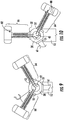
FIGS. 4 and 5 illustrate front views of embodiments of counterweight systems installed on rotatable hubs; -
FIGS. 6-16 illustrate an embodiment of method steps for individually mounting at least one blade to a balanced rotatable hub using at least one counterweight system and removable fluid. - Repeat use of reference characters in the present specification and drawings is intended to represent the same or analogous features or elements of the present disclosure.
- Reference now will be made in detail to embodiments of the invention, one or more examples of which are illustrated in the drawings. Each example is provided by way of explanation of the invention, not limitation of the invention. In fact, it will be apparent to those skilled in the art that various modifications and variations can be made in the present invention without departing from the scope or spirit of the invention. For instance, features illustrated or described as part of one embodiment can be used with another embodiment to yield a still further embodiment. Thus, it is intended that the present invention covers such modifications and variations as come within the scope of the appended claims and their equivalents.
- In general, the present subject matter discloses a method and device for single blade installation on a wind turbine which eliminates the need for an unbalanced rotor turning gear. Using a counterweight system and counterweight mass, with the ability to at least partially fill the counterweight mass with a fluid and/or solid mass portions, and also rotate an asymmetric counterweight fluid mass about the pitch axis with the pitch system, can increase or decrease the weight, and thus the torque, on the hub to rotate the rotor during assembly or maintenance. The method for mounting blades provides the ability to rotate an unbalanced rotor without the use of an unbalanced rotor turning gear, thereby eliminating the strain and load on the drive train. Most of the driving is done by gravity utilizing variable and rotatable fluidic or solid mass in the counterweight system. This method is particularly of value in direct drive machines, which are inherently difficult to perform rotation of the large rotors.
- Increasing tower heights and blade masses make a full rotor lift (hub and three blades) more and more impractical or even impossible. Therefore, the rotor has to be assembled in the air by first lifting the hub to the machine head and then installing each blade individually. The most convenient and safe position for a blade to be hoisted is in the horizontal position with the suction side down, sometimes using lifting frames. After the first blade is installed, the hub needs to be rotated through 120 degrees to position the next axis of the second blade..
- Referring now to the drawings,
FIG. 1 illustrates a perspective view of one embodiment of awind turbine 10 of conventional construction. As shown, thewind turbine 10 includes atower 12 extending from asupport surface 14, anacelle 16 mounted on thetower 12, and arotor 18 coupled to thenacelle 16. Therotor 18 includes arotatable hub 20 and at least onerotor blade 22 coupled to and extending outwardly from thehub 20. For example, in the illustrated embodiment, therotor 18 includes threerotor blades 22. However, in an alternative embodiment, therotor 18 may include more or less than threerotor blades 22. Eachrotor blade 22 may be spaced about thehub 20 to facilitate rotating therotor 18 to enable kinetic energy to be transferred from the wind into usable mechanical energy, and subsequently, electrical energy. For instance, thehub 20 may be rotatably coupled to an electric generator 24 (FIG. 2 ) positioned within thenacelle 16 to permit electrical energy to be produced. - Referring now to
FIG. 2 , a simplified, internal view of one embodiment of anacelle 16 of awind turbine 10 is illustrated. As shown, agenerator 24 may be disposed within thenacelle 16. In general, thegenerator 24 may be coupled to therotor 18 of thewind turbine 10 for producing electrical power from the rotational energy generated by therotor 18. For example, as shown in the illustrated embodiment, therotor 18 may include arotor shaft 32 coupled to thehub 20 for rotation therewith. Apitch system 48 is positioned inside therotatable hub 20 to individually rotate each of therotor blades 22 about their respective pitch axis. Therotor shaft 32 may, in turn, be rotatably coupled to agenerator shaft 34, sometimes referred to as the high speed shaft (HSS), of thegenerator 24 through agearbox 36 having a gearbox output shaft. As is generally understood, therotor shaft 32 may provide a low speed, high torque input to thegearbox 36 in response to rotation of therotor blades 22 and thehub 20. Thegearbox 36 may then be configured to convert the low speed, high torque input to a high speed, low torque output to drive the generator shaft 34 (HSS), and thus, thegenerator 24. -
FIG. 3 is an internal side view of a portion of thenacelle 16 in accordance with an embodiment of the present invention. Thebedplate assembly 38 includes therotor shaft 32 with a first end coupled to therotatable hub 20 of the wind turbine 10 (as shown inFIG. 1 ). Therotor shaft 32 also includes an opposite end coupled to thegearbox 36. Arotor locking disk 40 is coupled to first end of therotor shaft 32. Therotor locking disk 40 defines a plurality ofopenings 46 each extending throughrotor locking disk 40 and positioned circumferentially aboutrotor locking disk 40. Thebedplate assembly 38 further includes arotor lock 42 at a lower section of thebedplate assembly 38 and towards the front section. Therotor lock 42 is configured as a low speed rotor lock to stop and lock the rotation of therotor shaft 32 and the rotor blades 22 (shown inFIG. 1 ) by insertion of the pointedportion 44 of therotor lock 42 within any of themultiple openings 46 in therotor locking disk 40 during blade mounting and maintenance of thewind turbine 10. -
FIGS. 4 and 5 illustrate embodiments of acounterweight system 70 for individually mounting arotor blade 22 on a balancedrotatable hub 20 of awind turbine 10. Therotatable hub 20 can be mounted to anacelle 16, and can have at least oneblade root region rotor blade 22. Therotatable hub 20 can also have apitch system 48 configured to rotate therotor blade 22 andcounterweight system 70 around apitch axis 50. Thecounterweight system 70 can have at least onesupport structure 72 having aproximal end 74 spaced apart from adistal end 76, theproximal end 74 mountable to at least oneblade root region rotatable hub 20. At least onecounterweight mass 78 can be at least partially filled withfluid 80, thecounterweight mass 78 being coupled to thedistal end 76 of thesupport structure 72. Thesupport structure 72 can be arranged substantially parallel to thepitch axis 50 such that thepitch system 48 can rotate thecounterweight mass 78 about thepitch axis 50. - When the
pitch system 48 rotates thecounterweight mass 78 about thepitch axis 50, thecentroid 82 of thecounterweight mass 78 can be varied in a radial direction R, caused by repositioning the fluid 80 or solid mass of thecounterweight mass 78 as it rotates about thepitch axis 50, which changes the length of a counterweight mass moment arm M about the axial centerline of therotatable hub 56, and thus the torque on therotatable hub 20. Since the axial centerline of thecounterweight mass 58 is not perpendicular to thepitch axis 50, and is instead positioned at an angle theta (θ) with respect to thepitch axis 50, pitch rotation of thecounterweight mass 78, and any fluid or solid mass therein, will incrementally vary the torque on therotatable hub 20 with thecounterweight system 70 in any angular rotor position, including horizontal. The angle theta (θ) is generally a fixed angle in the range of about 30 degrees to about 89 degrees, which delivers non-perpendicular rotation of thecounterweight mass centroid 82 about thepitch axis 50. Pitch rotation of thecounterweight mass 78 allows for small increments of torque to be added or removed from therotatable hub 56 for 'fine-tuning' the hub position while mounting blades and counterweight systems as well as positioning theopenings 46 in therotor locking disc 40 for locking the rotor with therotor lock 42. Afluid pumping system 86 can be provided for at least partially filling and emptying the at least onecounterweight mass 78. The overall shape of thecounterweight mass 78 can be at least one of round, cylindrical, square, rectangular, elliptical, and combinations thereof. - Another structural configuration of a
counterweight system 70 that can provide variable torque on therotatable hub 20 during pitch rotation is to subdivide thecounterweight mass 78 into individually fluid-fillable portions 84 or solidmass portions 84, and combinations thereof, that are positioned at different distances from the axial centerline of therotatable hub 56, and progressively at least partially filling and emptying the individually fluid-fillable portions 84 until the desired rotor balance and position is obtained. Afluid pumping system 86 can be provided for at least partially filling and emptying the at least onecounterweight mass 78 fluid-fillable portions 84. Also, with therotatable hub 20 configured to rotate a plurality ofblades 22, and with thecounterweight mass 78 substantially equal to the mass of oneblade 22, each counterweight system can simulate the behavior of asingle blade 22 mounted to therotatable hub 20. - A structural configuration that can provide variable torque on the
rotatable hub 20, without pitch rotation, can be provided by constructing thesupport structure 72 to be at least partially telescopic such that the distance between the proximate 74 and distal ends 76 of thesupport structure 72 can be changed. This will move the axial centerline of thecounterweight mass 58 in a radial direction R to vary the torque on therotatable hub 20. It should be appreciated that the variable-torque effect provided by adjusting the distance between the proximate 74 and distal ends 76 of thesupport structure 72 can be accomplished in many ways, such as coupling thecounterweight mass 78 to a rail system that allows thecounterweight mass 78 to be controllably positioned along the length of thesupport structure 72. It should also be appreciated that thecounterweight system 70 disclosed herein can be used on either a gearbox driven wind turbine or a direct drive wind turbine, as well as on any equipment having a rotatable hub with removable attachments. -
FIGS. 6 - 16 illustrate a method of individually mounting at least oneblade rotatable hub 20 of awind turbine 10 using at least onecounterweight system removable fluid 80, wherein the at least onecounterweight system blade root region rotatable hub 20 having apitch system 48. The method steps can include: engaging arotor lock 42 to stop rotation of a balancedrotatable hub 20 and installing afirst blade 61 onto a firstblade root region 51 of the balancedrotatable hub 20, thefirst blade 61 positioned in a horizontal direction (seeFIG. 6 ); then disengaging therotor lock 42 so that the rotor freely rotates therotatable hub 20 to position thefirst blade 61 in a vertical downward direction (seeFIG. 7 ); then installing afirst counterweight system 64 onto a thirdblade root region 53 of therotatable hub 20, thefirst counterweight system 64 containing no fluid (seeFIG. 8 ); then installing asecond counterweight system 66 onto a secondblade root region 52 of therotatable hub 20, thesecond counterweight system 66 containing no fluid (seeFIG. 9 ); then at least partially filling thefirst counterweight system 64 withfluid 80 until therotatable hub 20 becomes balanced and rotates acounterweight mass centroid 82 of thesecond counterweight system 66 past the vertical upward direction on the opposing side of the first blade 61 (seeFIGS. 10 and11 ); then at least partially filling thesecond counterweight system 66 with fluid while simultaneously emptying thefirst counterweight system 64 to rotate the balancedrotatable hub 20 until thesecond counterweight system 66 reaches a horizontal position. - Additional method steps can be: engaging the
rotor lock 42 to stop rotation of the balanced rotatable hub 20 (seeFIG. 12 ); then uninstalling thesecond counterweight system 66 from the secondblade root region 52, and installing asecond blade 62 onto the empty secondblade root region 52 of the rotatable hub, thesecond blade 62 positioned in a horizontal direction (seeFIG. 13 ); then at least partially filling thefirst counterweight system 64 withfluid 80 until therotatable hub 20 is balanced (i.e., when the mass of thefirst counterweight system 64 equals the mass of a blade 63) (seeFIG. 14 ); then rotating the balancedrotatable hub 20 until thefirst counterweight system 64 is in a horizontal position and engaging therotor lock 42 to stop rotation of the balanced rotatable hub 10 (seeFIG. 15 ); then uninstalling thefirst counterweight system 64 from the thirdblade root region 53, and installing athird blade 63 onto the empty thirdblade root region 53 of therotatable hub 20, thethird blade 63 positioned in a horizontal direction, and then disengaging therotor lock 42 so that the balanced rotor is free to rotate with all threeblades FIG. 16 ). - A method can also include; operating the
pitch system 48 to rotate at least one of the first andsecond counterweight systems pitch axis 50 to vary at least onecounterweight mass 78centroid 82 in the radial direction R ,thereby changing the length of a counterweight mass moment arm M about the axial centerline of therotatable hub 56, thereby positioning the balancedrotatable hub 20 for mounting and locking. Additional method steps can also include; operating afluid pumping system 86 to fill and empty the first andsecond counterweight systems telescopic support structure 72 such that a distance between the proximate 74 and distal ends 76 of thesupport structure 72 is changed. - This written description uses examples to disclose the invention, including the best mode, and also to enable any person skilled in the art to practice the invention, including making and using any devices or systems and performing any incorporated methods. The patentable scope of the invention is defined by the claims, and may include other examples that occur to those skilled in the art. Such other examples are intended to be within the scope of the claims if they include structural elements that do not differ from the literal language of the claims, or if they include equivalent structural elements with insubstantial differences from the literal languages of the claims.
Reference Character Component 10 Wind Turbine 12 Tower 14 Support Surface 16 Nacelle 18 Rotor 20 Rotatable Hub 22 Rotor Blades 24 Electric Generator 26 Turbine Controller 28 Wind Direction 30 Yaw Axis 32 Rotor Shaft 34 Generator Shaft 35 Gearbox Output Shaft 36 Gearbox 38 Bedplate 40 Rotor Locking Disk 42 Rotor Lock 44 Pointed Portion 46 Openings 48 Pitch System 50 Pitch Axis 51 First Blade Root Region 52 Second Blade Root Region 53 Third Blade Root Region 56 Axial Centerline of Rotatable Hub 58 Axial Centerline of Counterweight Mass 61 First Blade 62 Second Blade 63 Third Blade 64 First Counterweight System 66 Second Counterweight System 70 Counterweight System 72 Support Structure 74 Proximal End 76 Distal End 78 Counterweight Mass 80 Fluid 82 Centroid 84 Individually Fluid- fillable Portions 86 Fluid Pumping System
Claims (20)
- A counterweight system for mounting a rotor blade on a balanced rotatable hub of a wind turbine, the rotatable hub mounted to a nacelle and having at least one blade root region configured to receive a blade root of the rotor blade, and a pitch system configured to rotate the rotor blade around a pitch axis, the counterweight system comprising;
at least one support structure comprising a proximal end spaced apart from a distal end, the proximal end mountable to at least one blade root region of the rotatable hub,
at least one counterweight mass coupled to the distal end of the at least one support structure, the at least one support structure arranged substantially parallel to the pitch axis such that the pitch system rotates the counterweight mass about the pitch axis, and,
wherein a centroid of the at least one counterweight mass is varied in a radial direction, as the counterweight mass rotates about the pitch axis, to change the length of a counterweight mass moment arm about an axial centerline of the rotatable hub. - The counterweight system of claim 1, wherein an overall shape of the counterweight mass is at least one of round, cylindrical, square, rectangular, elliptical, and combinations thereof.
- The counterweight system of claim 3, wherein an axial centerline of the at least one counterweight mass is non-perpendicular to the pitch axis.
- The counterweight system of claim 1, wherein the counterweight mass is subdivided into at least one of individually fluid-fillable portions or solid mass portions and combinations thereof.
- The counterweight system of claim 1, wherein the rotatable hub is configured to rotate a plurality of blades, and wherein the product of the counterweight mass times the counterweight mass moment arm is substantially equal to the product of the mass of a single blade times the blade moment arm.
- The counterweight system of claim 1, wherein the support structure is at least partially telescopic such that a distance between the proximate and distal ends of the support structure can be changed.
- The counterweight system of claim 1, wherein the at least one counterweight mass is at least partially fluid-fillable.
- The counterweight system of claim 7, further comprising a fluid pumping system for at least partially filling and emptying the at least one counterweight mass.
- The counterweight system of claim 1, wherein the wind turbine is one of a gearbox driven wind turbine or a direct drive wind turbine.
- A wind turbine, comprising;
a tower;
a nacelle mounted atop the tower;
a generator coupled to a main frame within the nacelle;
a counterweight system for mounting a rotor blade on a balanced rotatable hub of the wind turbine, the rotatable hub mounted to the nacelle and having at least one blade root region configured to receive a blade root of the rotor blade, and a pitch system configured to rotate the rotor blade around a pitch axis, the counterweight system comprising;
at least one support structure comprising a proximal end spaced apart from a distal end, the proximal end mountable to the at least one blade root region of the rotatable hub, and,
at least one counterweight mass coupled to the distal end of the at least one support structure, the at least one support structure arranged substantially parallel to the pitch axis such that the pitch system rotates the counterweight mass about the pitch axis, and,
wherein a centroid of the at least one counterweight mass is varied in a radial direction as the counterweight mass rotates about the pitch axis to adjust the length of a counterweight mass moment arm about the axial centerline of the rotatable hub. - The wind turbine of claim 10, wherein an overall shape of the counterweight mass is at least one of round, cylindrical, square, rectangular, elliptical, and combinations thereof.
- The wind turbine of claim 11, wherein the axial centerline of the at least one counterweight mass is non-perpendicular to the pitch axis.
- The wind turbine of claim 10, wherein the counterweight mass is subdivided into at least one of individually fluid-fillable portions or solid mass portions and combinations thereof.
- The wind turbine of claim 10, wherein the rotatable hub is configured to rotate a plurality of blades, and wherein the product of the counterweight mass times the counterweight mass moment arm is substantially equal to the product of the mass of a single blade times the blade moment arm.
- The wind turbine of claim 10, wherein the support structure is at least partially telescopic such that a distance between the proximate and distal ends of the support structure can be varied.
- The wind turbine of claim 10, wherein the at least one counterweight mass is at least partially fluid-fillable, and wherein the wind turbine further comprises a fluid pumping system for at least partially filling and emptying the at least one counterweight mass.
- A method of individually mounting at least one blade to a balanced rotatable hub of a wind turbine using at least one counterweight system, wherein the at least one counterweight system is mounted to at least one blade root region of the rotatable hub having a pitch system, the method comprising:engaging a rotor lock to stop rotation of a balanced rotatable hub;installing a first blade onto a first blade root region of the balanced rotatable hub, the first blade positioned in a horizontal direction;disengaging the rotor lock so that the rotor freely rotates the rotatable hub to position the first blade in a vertical downward direction;installing a first counterweight system onto a third blade root region of the rotatable hub, the first counterweight system containing no fluid;installing a second counterweight system onto a second blade root region of the rotatable hub, the second counterweight system containing no fluid;at least partially filling the first counterweight system with fluid until the rotatable hub becomes balanced and rotates a counterweight mass centroid of the second counterweight system past the vertical upward direction on the opposing side of the first blade; and,at least partially filling the second counterweight system with fluid while simultaneously at least partially emptying the first counterweight system to freely rotate the balanced rotatable hub until the second counterweight system reaches a horizontal position.
- The method of claim 17, further comprising:engaging the rotor lock to stop rotation of the balanced rotatable hub;uninstalling the second counterweight system from the second blade root region;installing a second blade onto the empty second blade root region of the rotatable hub, the second blade positioned in a horizontal direction;at least partially filling the first counterweight system with fluid until the rotatable hub is balanced;rotating the balanced rotatable hub until the first counterweight system is in a horizontal position;engaging the rotor lock to stop rotation of the balanced rotatable hub;uninstalling the first counterweight system from the third blade root region;installing a third blade onto the empty third blade root region of the rotatable hub, the third blade positioned in a horizontal direction; anddisengaging the rotor lock so that the balanced rotor is free to rotate with all three blades attached.
- The method of claim 18, further comprising operating the pitch system to rotate at least one of the first and second counterweight systems about a pitch axis to vary at least one counterweight mass centroid in the radial direction thereby changing the length of a counterweight mass moment arm about the axial centerline of the rotatable hub, thereby positioning the balanced rotatable hub for mounting and locking.
- The method of claim 18, further comprising operating the at least partially telescopic support structure such that a distance between the proximate and distal ends of the support structure is changed.
Priority Applications (4)
| Application Number | Priority Date | Filing Date | Title |
|---|---|---|---|
| EP17382609.0A EP3456957B1 (en) | 2017-09-15 | 2017-09-15 | Counterweight system for balanced hub wind turbine blade installation |
| DK17382609.0T DK3456957T3 (en) | 2017-09-15 | 2017-09-15 | Modvægtssystem til balanceret navvindmølleinstallation |
| ES17382609T ES2952861T3 (en) | 2017-09-15 | 2017-09-15 | Counterweight system for the installation of balanced bushing wind turbine blades |
| US16/117,016 US10830204B2 (en) | 2017-09-15 | 2018-08-30 | Counterweight system for balanced hub wind turbine blade installation |
Applications Claiming Priority (1)
| Application Number | Priority Date | Filing Date | Title |
|---|---|---|---|
| EP17382609.0A EP3456957B1 (en) | 2017-09-15 | 2017-09-15 | Counterweight system for balanced hub wind turbine blade installation |
Publications (2)
| Publication Number | Publication Date |
|---|---|
| EP3456957A1 true EP3456957A1 (en) | 2019-03-20 |
| EP3456957B1 EP3456957B1 (en) | 2023-05-31 |
Family
ID=59895253
Family Applications (1)
| Application Number | Title | Priority Date | Filing Date |
|---|---|---|---|
| EP17382609.0A Active EP3456957B1 (en) | 2017-09-15 | 2017-09-15 | Counterweight system for balanced hub wind turbine blade installation |
Country Status (4)
| Country | Link |
|---|---|
| US (1) | US10830204B2 (en) |
| EP (1) | EP3456957B1 (en) |
| DK (1) | DK3456957T3 (en) |
| ES (1) | ES2952861T3 (en) |
Cited By (2)
| Publication number | Priority date | Publication date | Assignee | Title |
|---|---|---|---|---|
| CN113365916A (en) * | 2019-06-25 | 2021-09-07 | 列奥纳多股份公司 | Anti-torque rotor for helicopter |
| US11686291B2 (en) | 2021-01-12 | 2023-06-27 | General Electric Renovables Espana, S.L. | Method of mounting blades to a rotor hub of a wind turbine |
Families Citing this family (8)
| Publication number | Priority date | Publication date | Assignee | Title |
|---|---|---|---|---|
| EP3830411B1 (en) * | 2018-07-27 | 2023-03-15 | Vestas Wind Systems A/S | Method of installing a rotor on a wind turbine, a rotor hub and counterweight assembly |
| US10823138B2 (en) * | 2018-08-31 | 2020-11-03 | General Electric Company | Counterweight assembly for use during single blade installation of a wind turbine |
| CN109989878B (en) * | 2019-04-28 | 2023-08-25 | 福州大学 | Electromagnetic Wind Power Generator Impeller Unbalance Compensation Device and Method |
| ES2966934T3 (en) * | 2019-12-31 | 2024-04-25 | Nordex Energy Spain Sau | Blade mounting method on a wind turbine rotor hub |
| CN113187675B (en) * | 2021-05-08 | 2023-03-21 | 天津派特瑞科技有限公司 | Method for adjusting dynamic balance of fan blade |
| EP4170158A1 (en) * | 2021-10-22 | 2023-04-26 | Siemens Gamesa Renewable Energy A/S | Method of mounting a wind turbine rotor blade |
| CN117432574B (en) * | 2023-12-20 | 2024-04-19 | 苏州天顺复合材料科技有限公司 | Wind-powered electricity generation blade is with exempting from to stand up installation fastener |
| EP4656872A1 (en) * | 2024-05-28 | 2025-12-03 | Nederlandse Organisatie voor toegepast-natuurwetenschappelijk Onderzoek TNO | Wind turbine with high tip mass and tensioning member |
Citations (5)
| Publication number | Priority date | Publication date | Assignee | Title |
|---|---|---|---|---|
| US20040253109A1 (en) * | 2001-07-20 | 2004-12-16 | Aloys Wobben | Method for in situ construction of a wind power plant |
| DE102009011603A1 (en) * | 2009-03-04 | 2010-09-09 | Klaus Würthele | Rotor blade assembling device for wind power plant, has counterweights arranged at different distances to rotation axis, where mass distribution of rotor is changed during assembling rotor blade by adding counterweights |
| KR101400205B1 (en) * | 2013-02-06 | 2014-05-27 | 삼성중공업 주식회사 | Balancing device and method for mounting wind turbine blade using the same |
| EP2924284A1 (en) * | 2014-03-28 | 2015-09-30 | Alstom Renovables España, S.L. | Counterweighting a wind turbine hub |
| KR101607691B1 (en) * | 2015-02-11 | 2016-03-30 | 삼성중공업 주식회사 | Balance providing apparatus |
-
2017
- 2017-09-15 EP EP17382609.0A patent/EP3456957B1/en active Active
- 2017-09-15 DK DK17382609.0T patent/DK3456957T3/en active
- 2017-09-15 ES ES17382609T patent/ES2952861T3/en active Active
-
2018
- 2018-08-30 US US16/117,016 patent/US10830204B2/en active Active
Patent Citations (5)
| Publication number | Priority date | Publication date | Assignee | Title |
|---|---|---|---|---|
| US20040253109A1 (en) * | 2001-07-20 | 2004-12-16 | Aloys Wobben | Method for in situ construction of a wind power plant |
| DE102009011603A1 (en) * | 2009-03-04 | 2010-09-09 | Klaus Würthele | Rotor blade assembling device for wind power plant, has counterweights arranged at different distances to rotation axis, where mass distribution of rotor is changed during assembling rotor blade by adding counterweights |
| KR101400205B1 (en) * | 2013-02-06 | 2014-05-27 | 삼성중공업 주식회사 | Balancing device and method for mounting wind turbine blade using the same |
| EP2924284A1 (en) * | 2014-03-28 | 2015-09-30 | Alstom Renovables España, S.L. | Counterweighting a wind turbine hub |
| KR101607691B1 (en) * | 2015-02-11 | 2016-03-30 | 삼성중공업 주식회사 | Balance providing apparatus |
Cited By (4)
| Publication number | Priority date | Publication date | Assignee | Title |
|---|---|---|---|---|
| CN113365916A (en) * | 2019-06-25 | 2021-09-07 | 列奥纳多股份公司 | Anti-torque rotor for helicopter |
| CN113365916B (en) * | 2019-06-25 | 2024-05-07 | 列奥纳多股份公司 | Anti-torque rotor for helicopters |
| US12071230B2 (en) | 2019-06-25 | 2024-08-27 | Leonardo S.P.A. | Anti-torque rotor for a helicopter |
| US11686291B2 (en) | 2021-01-12 | 2023-06-27 | General Electric Renovables Espana, S.L. | Method of mounting blades to a rotor hub of a wind turbine |
Also Published As
| Publication number | Publication date |
|---|---|
| US20190085818A1 (en) | 2019-03-21 |
| ES2952861T3 (en) | 2023-11-06 |
| EP3456957B1 (en) | 2023-05-31 |
| US10830204B2 (en) | 2020-11-10 |
| DK3456957T3 (en) | 2023-08-28 |
Similar Documents
| Publication | Publication Date | Title |
|---|---|---|
| US10830204B2 (en) | Counterweight system for balanced hub wind turbine blade installation | |
| CN102032113B (en) | Systems and methods for assembling a pitch control assembly for use in a wind turbine | |
| KR101143784B1 (en) | Tower for a windmill and wind power generator | |
| EP2924283B1 (en) | Counterweighting a wind turbine hub | |
| CN102374114B (en) | For the wheel hub of wind turbine and the method for mounting wind | |
| US20090250939A1 (en) | Wind-driven generation of power | |
| KR101699647B1 (en) | Wind turbine | |
| EP2924284B1 (en) | Counterweighting a wind turbine hub | |
| EP2620644A1 (en) | Improvements to a wind turbine assembly | |
| CN110892154A (en) | Vertical wind power plant with pitch motor carrying rotor blades and mounting kit therefor and method for its operation | |
| US20090322085A1 (en) | Method and apparatus for enhanced wind turbine design | |
| KR20230164590A (en) | Assemblies for wind turbines and methods | |
| EP3085958A1 (en) | A system for installing a cable in a tower of a wind turbine and method therefor | |
| US11965479B2 (en) | System and method for repairing a gearbox of a wind turbine uptower | |
| US10641042B2 (en) | External ladder assembly for wind turbine nacelle | |
| KR102051561B1 (en) | Rotor rotation device of wind turbine for assembling blade | |
| EP2927480B1 (en) | Wind turbine rotor rotation | |
| WO2018200907A1 (en) | Working platform within a nacelle of a wind turbine | |
| EP4438890A1 (en) | Rotating unbalanced rotor hubs and installing wind turbine rotor blades | |
| US20230323860A1 (en) | Wind turbine frame with flexible coupling | |
| EP3431757A1 (en) | External platform assembly for wind turbine repairs | |
| JP2023038913A (en) | nacelle cover panel | |
| EP4414555B1 (en) | Couplings and auxiliary components for wind turbines, and associated methods | |
| WO2025247493A1 (en) | Methods for installing wind turbine blades | |
| WO2025247492A1 (en) | Methods, sets and blades for installation of a wind turbine blade |
Legal Events
| Date | Code | Title | Description |
|---|---|---|---|
| PUAI | Public reference made under article 153(3) epc to a published international application that has entered the european phase |
Free format text: ORIGINAL CODE: 0009012 |
|
| STAA | Information on the status of an ep patent application or granted ep patent |
Free format text: STATUS: REQUEST FOR EXAMINATION WAS MADE |
|
| 17P | Request for examination filed |
Effective date: 20170915 |
|
| AK | Designated contracting states |
Kind code of ref document: A1 Designated state(s): AL AT BE BG CH CY CZ DE DK EE ES FI FR GB GR HR HU IE IS IT LI LT LU LV MC MK MT NL NO PL PT RO RS SE SI SK SM TR |
|
| AX | Request for extension of the european patent |
Extension state: BA ME |
|
| RBV | Designated contracting states (corrected) |
Designated state(s): AL AT BE BG CH CY CZ DE DK EE ES FI FR GB GR HR HU IE IS IT LI LT LU LV MC MK MT NL NO PL PT RO RS SE SI SK SM TR |
|
| STAA | Information on the status of an ep patent application or granted ep patent |
Free format text: STATUS: EXAMINATION IS IN PROGRESS |
|
| 17Q | First examination report despatched |
Effective date: 20210715 |
|
| GRAP | Despatch of communication of intention to grant a patent |
Free format text: ORIGINAL CODE: EPIDOSNIGR1 |
|
| STAA | Information on the status of an ep patent application or granted ep patent |
Free format text: STATUS: GRANT OF PATENT IS INTENDED |
|
| INTG | Intention to grant announced |
Effective date: 20230130 |
|
| GRAS | Grant fee paid |
Free format text: ORIGINAL CODE: EPIDOSNIGR3 |
|
| GRAA | (expected) grant |
Free format text: ORIGINAL CODE: 0009210 |
|
| STAA | Information on the status of an ep patent application or granted ep patent |
Free format text: STATUS: THE PATENT HAS BEEN GRANTED |
|
| AK | Designated contracting states |
Kind code of ref document: B1 Designated state(s): AL AT BE BG CH CY CZ DE DK EE ES FI FR GB GR HR HU IE IS IT LI LT LU LV MC MK MT NL NO PL PT RO RS SE SI SK SM TR |
|
| REG | Reference to a national code |
Ref country code: GB Ref legal event code: FG4D Ref country code: CH Ref legal event code: EP |
|
| REG | Reference to a national code |
Ref country code: AT Ref legal event code: REF Ref document number: 1571069 Country of ref document: AT Kind code of ref document: T Effective date: 20230615 Ref country code: DE Ref legal event code: R096 Ref document number: 602017069189 Country of ref document: DE |
|
| REG | Reference to a national code |
Ref country code: IE Ref legal event code: FG4D |
|
| P01 | Opt-out of the competence of the unified patent court (upc) registered |
Effective date: 20230530 |
|
| REG | Reference to a national code |
Ref country code: DK Ref legal event code: T3 Effective date: 20230821 |
|
| REG | Reference to a national code |
Ref country code: LT Ref legal event code: MG9D |
|
| REG | Reference to a national code |
Ref country code: NL Ref legal event code: MP Effective date: 20230531 |
|
| REG | Reference to a national code |
Ref country code: AT Ref legal event code: MK05 Ref document number: 1571069 Country of ref document: AT Kind code of ref document: T Effective date: 20230531 |
|
| PG25 | Lapsed in a contracting state [announced via postgrant information from national office to epo] |
Ref country code: SE Free format text: LAPSE BECAUSE OF FAILURE TO SUBMIT A TRANSLATION OF THE DESCRIPTION OR TO PAY THE FEE WITHIN THE PRESCRIBED TIME-LIMIT Effective date: 20230531 Ref country code: NO Free format text: LAPSE BECAUSE OF FAILURE TO SUBMIT A TRANSLATION OF THE DESCRIPTION OR TO PAY THE FEE WITHIN THE PRESCRIBED TIME-LIMIT Effective date: 20230831 Ref country code: AT Free format text: LAPSE BECAUSE OF FAILURE TO SUBMIT A TRANSLATION OF THE DESCRIPTION OR TO PAY THE FEE WITHIN THE PRESCRIBED TIME-LIMIT Effective date: 20230531 |
|
| REG | Reference to a national code |
Ref country code: ES Ref legal event code: FG2A Ref document number: 2952861 Country of ref document: ES Kind code of ref document: T3 Effective date: 20231106 |
|
| PG25 | Lapsed in a contracting state [announced via postgrant information from national office to epo] |
Ref country code: RS Free format text: LAPSE BECAUSE OF FAILURE TO SUBMIT A TRANSLATION OF THE DESCRIPTION OR TO PAY THE FEE WITHIN THE PRESCRIBED TIME-LIMIT Effective date: 20230531 Ref country code: PL Free format text: LAPSE BECAUSE OF FAILURE TO SUBMIT A TRANSLATION OF THE DESCRIPTION OR TO PAY THE FEE WITHIN THE PRESCRIBED TIME-LIMIT Effective date: 20230531 Ref country code: NL Free format text: LAPSE BECAUSE OF FAILURE TO SUBMIT A TRANSLATION OF THE DESCRIPTION OR TO PAY THE FEE WITHIN THE PRESCRIBED TIME-LIMIT Effective date: 20230531 Ref country code: LV Free format text: LAPSE BECAUSE OF FAILURE TO SUBMIT A TRANSLATION OF THE DESCRIPTION OR TO PAY THE FEE WITHIN THE PRESCRIBED TIME-LIMIT Effective date: 20230531 Ref country code: LT Free format text: LAPSE BECAUSE OF FAILURE TO SUBMIT A TRANSLATION OF THE DESCRIPTION OR TO PAY THE FEE WITHIN THE PRESCRIBED TIME-LIMIT Effective date: 20230531 Ref country code: IS Free format text: LAPSE BECAUSE OF FAILURE TO SUBMIT A TRANSLATION OF THE DESCRIPTION OR TO PAY THE FEE WITHIN THE PRESCRIBED TIME-LIMIT Effective date: 20230930 Ref country code: HR Free format text: LAPSE BECAUSE OF FAILURE TO SUBMIT A TRANSLATION OF THE DESCRIPTION OR TO PAY THE FEE WITHIN THE PRESCRIBED TIME-LIMIT Effective date: 20230531 Ref country code: GR Free format text: LAPSE BECAUSE OF FAILURE TO SUBMIT A TRANSLATION OF THE DESCRIPTION OR TO PAY THE FEE WITHIN THE PRESCRIBED TIME-LIMIT Effective date: 20230901 |
|
| REG | Reference to a national code |
Ref country code: DE Ref legal event code: R081 Ref document number: 602017069189 Country of ref document: DE Owner name: GENERAL ELECTRIC RENOVABLES ESPANA, S.L., ES Free format text: FORMER OWNER: GENERAL ELECTRIC COMPANY, SCHENECTADY, NY, US Ref country code: DE Ref legal event code: R082 Ref document number: 602017069189 Country of ref document: DE Ref country code: DE Ref legal event code: R082 Ref document number: 602017069189 Country of ref document: DE Representative=s name: ZIMMERMANN & PARTNER PATENTANWAELTE MBB, DE |
|
| RAP2 | Party data changed (patent owner data changed or rights of a patent transferred) |
Owner name: GENERAL ELECTRIC RENOVABLES ESPANA, S.L. |
|
| PG25 | Lapsed in a contracting state [announced via postgrant information from national office to epo] |
Ref country code: FI Free format text: LAPSE BECAUSE OF FAILURE TO SUBMIT A TRANSLATION OF THE DESCRIPTION OR TO PAY THE FEE WITHIN THE PRESCRIBED TIME-LIMIT Effective date: 20230531 |
|
| PG25 | Lapsed in a contracting state [announced via postgrant information from national office to epo] |
Ref country code: SK Free format text: LAPSE BECAUSE OF FAILURE TO SUBMIT A TRANSLATION OF THE DESCRIPTION OR TO PAY THE FEE WITHIN THE PRESCRIBED TIME-LIMIT Effective date: 20230531 |
|
| PG25 | Lapsed in a contracting state [announced via postgrant information from national office to epo] |
Ref country code: SM Free format text: LAPSE BECAUSE OF FAILURE TO SUBMIT A TRANSLATION OF THE DESCRIPTION OR TO PAY THE FEE WITHIN THE PRESCRIBED TIME-LIMIT Effective date: 20230531 Ref country code: SK Free format text: LAPSE BECAUSE OF FAILURE TO SUBMIT A TRANSLATION OF THE DESCRIPTION OR TO PAY THE FEE WITHIN THE PRESCRIBED TIME-LIMIT Effective date: 20230531 Ref country code: RO Free format text: LAPSE BECAUSE OF FAILURE TO SUBMIT A TRANSLATION OF THE DESCRIPTION OR TO PAY THE FEE WITHIN THE PRESCRIBED TIME-LIMIT Effective date: 20230531 Ref country code: PT Free format text: LAPSE BECAUSE OF FAILURE TO SUBMIT A TRANSLATION OF THE DESCRIPTION OR TO PAY THE FEE WITHIN THE PRESCRIBED TIME-LIMIT Effective date: 20231002 Ref country code: EE Free format text: LAPSE BECAUSE OF FAILURE TO SUBMIT A TRANSLATION OF THE DESCRIPTION OR TO PAY THE FEE WITHIN THE PRESCRIBED TIME-LIMIT Effective date: 20230531 Ref country code: CZ Free format text: LAPSE BECAUSE OF FAILURE TO SUBMIT A TRANSLATION OF THE DESCRIPTION OR TO PAY THE FEE WITHIN THE PRESCRIBED TIME-LIMIT Effective date: 20230531 |
|
| REG | Reference to a national code |
Ref country code: DE Ref legal event code: R097 Ref document number: 602017069189 Country of ref document: DE |
|
| REG | Reference to a national code |
Ref country code: DE Ref legal event code: R082 Ref document number: 602017069189 Country of ref document: DE Representative=s name: ZIMMERMANN & PARTNER PATENTANWAELTE MBB, DE |
|
| PLBE | No opposition filed within time limit |
Free format text: ORIGINAL CODE: 0009261 |
|
| STAA | Information on the status of an ep patent application or granted ep patent |
Free format text: STATUS: NO OPPOSITION FILED WITHIN TIME LIMIT |
|
| REG | Reference to a national code |
Ref country code: CH Ref legal event code: PL |
|
| PG25 | Lapsed in a contracting state [announced via postgrant information from national office to epo] |
Ref country code: SI Free format text: LAPSE BECAUSE OF FAILURE TO SUBMIT A TRANSLATION OF THE DESCRIPTION OR TO PAY THE FEE WITHIN THE PRESCRIBED TIME-LIMIT Effective date: 20230531 |
|
| 26N | No opposition filed |
Effective date: 20240301 |
|
| PG25 | Lapsed in a contracting state [announced via postgrant information from national office to epo] |
Ref country code: LU Free format text: LAPSE BECAUSE OF NON-PAYMENT OF DUE FEES Effective date: 20230915 |
|
| REG | Reference to a national code |
Ref country code: BE Ref legal event code: MM Effective date: 20230930 |
|
| GBPC | Gb: european patent ceased through non-payment of renewal fee |
Effective date: 20230915 |
|
| PG25 | Lapsed in a contracting state [announced via postgrant information from national office to epo] |
Ref country code: SI Free format text: LAPSE BECAUSE OF FAILURE TO SUBMIT A TRANSLATION OF THE DESCRIPTION OR TO PAY THE FEE WITHIN THE PRESCRIBED TIME-LIMIT Effective date: 20230531 Ref country code: LU Free format text: LAPSE BECAUSE OF NON-PAYMENT OF DUE FEES Effective date: 20230915 Ref country code: IT Free format text: LAPSE BECAUSE OF FAILURE TO SUBMIT A TRANSLATION OF THE DESCRIPTION OR TO PAY THE FEE WITHIN THE PRESCRIBED TIME-LIMIT Effective date: 20230531 Ref country code: MC Free format text: LAPSE BECAUSE OF FAILURE TO SUBMIT A TRANSLATION OF THE DESCRIPTION OR TO PAY THE FEE WITHIN THE PRESCRIBED TIME-LIMIT Effective date: 20230531 |
|
| REG | Reference to a national code |
Ref country code: IE Ref legal event code: MM4A |
|
| PG25 | Lapsed in a contracting state [announced via postgrant information from national office to epo] |
Ref country code: IE Free format text: LAPSE BECAUSE OF NON-PAYMENT OF DUE FEES Effective date: 20230915 |
|
| PG25 | Lapsed in a contracting state [announced via postgrant information from national office to epo] |
Ref country code: GB Free format text: LAPSE BECAUSE OF NON-PAYMENT OF DUE FEES Effective date: 20230915 |
|
| PG25 | Lapsed in a contracting state [announced via postgrant information from national office to epo] |
Ref country code: CH Free format text: LAPSE BECAUSE OF NON-PAYMENT OF DUE FEES Effective date: 20230930 |
|
| PG25 | Lapsed in a contracting state [announced via postgrant information from national office to epo] |
Ref country code: IE Free format text: LAPSE BECAUSE OF NON-PAYMENT OF DUE FEES Effective date: 20230915 Ref country code: GB Free format text: LAPSE BECAUSE OF NON-PAYMENT OF DUE FEES Effective date: 20230915 Ref country code: FR Free format text: LAPSE BECAUSE OF NON-PAYMENT OF DUE FEES Effective date: 20230930 Ref country code: CH Free format text: LAPSE BECAUSE OF NON-PAYMENT OF DUE FEES Effective date: 20230930 |
|
| REG | Reference to a national code |
Ref country code: ES Ref legal event code: PC2A Owner name: GENERAL ELECTRIC RENOVABLES ESPANA S.L. Effective date: 20240809 |
|
| PG25 | Lapsed in a contracting state [announced via postgrant information from national office to epo] |
Ref country code: BE Free format text: LAPSE BECAUSE OF NON-PAYMENT OF DUE FEES Effective date: 20230930 |
|
| PG25 | Lapsed in a contracting state [announced via postgrant information from national office to epo] |
Ref country code: BG Free format text: LAPSE BECAUSE OF FAILURE TO SUBMIT A TRANSLATION OF THE DESCRIPTION OR TO PAY THE FEE WITHIN THE PRESCRIBED TIME-LIMIT Effective date: 20230531 |
|
| PG25 | Lapsed in a contracting state [announced via postgrant information from national office to epo] |
Ref country code: BG Free format text: LAPSE BECAUSE OF FAILURE TO SUBMIT A TRANSLATION OF THE DESCRIPTION OR TO PAY THE FEE WITHIN THE PRESCRIBED TIME-LIMIT Effective date: 20230531 |
|
| PG25 | Lapsed in a contracting state [announced via postgrant information from national office to epo] |
Ref country code: CY Free format text: LAPSE BECAUSE OF FAILURE TO SUBMIT A TRANSLATION OF THE DESCRIPTION OR TO PAY THE FEE WITHIN THE PRESCRIBED TIME-LIMIT; INVALID AB INITIO Effective date: 20170915 |
|
| PG25 | Lapsed in a contracting state [announced via postgrant information from national office to epo] |
Ref country code: HU Free format text: LAPSE BECAUSE OF FAILURE TO SUBMIT A TRANSLATION OF THE DESCRIPTION OR TO PAY THE FEE WITHIN THE PRESCRIBED TIME-LIMIT; INVALID AB INITIO Effective date: 20170915 |
|
| PGFP | Annual fee paid to national office [announced via postgrant information from national office to epo] |
Ref country code: DK Payment date: 20250820 Year of fee payment: 9 Ref country code: DE Payment date: 20250820 Year of fee payment: 9 |
|
| PG25 | Lapsed in a contracting state [announced via postgrant information from national office to epo] |
Ref country code: TR Free format text: LAPSE BECAUSE OF FAILURE TO SUBMIT A TRANSLATION OF THE DESCRIPTION OR TO PAY THE FEE WITHIN THE PRESCRIBED TIME-LIMIT Effective date: 20230531 |
|
| PGFP | Annual fee paid to national office [announced via postgrant information from national office to epo] |
Ref country code: ES Payment date: 20251001 Year of fee payment: 9 |