EP3456941A1 - Power transmission device - Google Patents
Power transmission device Download PDFInfo
- Publication number
- EP3456941A1 EP3456941A1 EP18203821.6A EP18203821A EP3456941A1 EP 3456941 A1 EP3456941 A1 EP 3456941A1 EP 18203821 A EP18203821 A EP 18203821A EP 3456941 A1 EP3456941 A1 EP 3456941A1
- Authority
- EP
- European Patent Office
- Prior art keywords
- shaft
- quill shaft
- oil
- power transmission
- transmission device
- Prior art date
- Legal status (The legal status is an assumption and is not a legal conclusion. Google has not performed a legal analysis and makes no representation as to the accuracy of the status listed.)
- Granted
Links
Images


Classifications
-
- F—MECHANICAL ENGINEERING; LIGHTING; HEATING; WEAPONS; BLASTING
- F16—ENGINEERING ELEMENTS AND UNITS; GENERAL MEASURES FOR PRODUCING AND MAINTAINING EFFECTIVE FUNCTIONING OF MACHINES OR INSTALLATIONS; THERMAL INSULATION IN GENERAL
- F16D—COUPLINGS FOR TRANSMITTING ROTATION; CLUTCHES; BRAKES
- F16D3/00—Yielding couplings, i.e. with means permitting movement between the connected parts during the drive
- F16D3/02—Yielding couplings, i.e. with means permitting movement between the connected parts during the drive adapted to specific functions
- F16D3/06—Yielding couplings, i.e. with means permitting movement between the connected parts during the drive adapted to specific functions specially adapted to allow axial displacement
-
- F—MECHANICAL ENGINEERING; LIGHTING; HEATING; WEAPONS; BLASTING
- F01—MACHINES OR ENGINES IN GENERAL; ENGINE PLANTS IN GENERAL; STEAM ENGINES
- F01D—NON-POSITIVE DISPLACEMENT MACHINES OR ENGINES, e.g. STEAM TURBINES
- F01D5/00—Blades; Blade-carrying members; Heating, heat-insulating, cooling or antivibration means on the blades or the members
- F01D5/02—Blade-carrying members, e.g. rotors
- F01D5/026—Shaft to shaft connections
-
- F—MECHANICAL ENGINEERING; LIGHTING; HEATING; WEAPONS; BLASTING
- F02—COMBUSTION ENGINES; HOT-GAS OR COMBUSTION-PRODUCT ENGINE PLANTS
- F02C—GAS-TURBINE PLANTS; AIR INTAKES FOR JET-PROPULSION PLANTS; CONTROLLING FUEL SUPPLY IN AIR-BREATHING JET-PROPULSION PLANTS
- F02C3/00—Gas-turbine plants characterised by the use of combustion products as the working fluid
- F02C3/04—Gas-turbine plants characterised by the use of combustion products as the working fluid having a turbine driving a compressor
- F02C3/107—Gas-turbine plants characterised by the use of combustion products as the working fluid having a turbine driving a compressor with two or more rotors connected by power transmission
-
- F—MECHANICAL ENGINEERING; LIGHTING; HEATING; WEAPONS; BLASTING
- F02—COMBUSTION ENGINES; HOT-GAS OR COMBUSTION-PRODUCT ENGINE PLANTS
- F02C—GAS-TURBINE PLANTS; AIR INTAKES FOR JET-PROPULSION PLANTS; CONTROLLING FUEL SUPPLY IN AIR-BREATHING JET-PROPULSION PLANTS
- F02C7/00—Features, components parts, details or accessories, not provided for in, or of interest apart form groups F02C1/00 - F02C6/00; Air intakes for jet-propulsion plants
- F02C7/06—Arrangements of bearings; Lubricating
-
- F—MECHANICAL ENGINEERING; LIGHTING; HEATING; WEAPONS; BLASTING
- F02—COMBUSTION ENGINES; HOT-GAS OR COMBUSTION-PRODUCT ENGINE PLANTS
- F02C—GAS-TURBINE PLANTS; AIR INTAKES FOR JET-PROPULSION PLANTS; CONTROLLING FUEL SUPPLY IN AIR-BREATHING JET-PROPULSION PLANTS
- F02C7/00—Features, components parts, details or accessories, not provided for in, or of interest apart form groups F02C1/00 - F02C6/00; Air intakes for jet-propulsion plants
- F02C7/36—Power transmission arrangements between the different shafts of the gas turbine plant, or between the gas-turbine plant and the power user
-
- F—MECHANICAL ENGINEERING; LIGHTING; HEATING; WEAPONS; BLASTING
- F16—ENGINEERING ELEMENTS AND UNITS; GENERAL MEASURES FOR PRODUCING AND MAINTAINING EFFECTIVE FUNCTIONING OF MACHINES OR INSTALLATIONS; THERMAL INSULATION IN GENERAL
- F16D—COUPLINGS FOR TRANSMITTING ROTATION; CLUTCHES; BRAKES
- F16D1/00—Couplings for rigidly connecting two coaxial shafts or other movable machine elements
- F16D1/10—Quick-acting couplings in which the parts are connected by simply bringing them together axially
-
- F—MECHANICAL ENGINEERING; LIGHTING; HEATING; WEAPONS; BLASTING
- F16—ENGINEERING ELEMENTS AND UNITS; GENERAL MEASURES FOR PRODUCING AND MAINTAINING EFFECTIVE FUNCTIONING OF MACHINES OR INSTALLATIONS; THERMAL INSULATION IN GENERAL
- F16D—COUPLINGS FOR TRANSMITTING ROTATION; CLUTCHES; BRAKES
- F16D3/00—Yielding couplings, i.e. with means permitting movement between the connected parts during the drive
- F16D3/02—Yielding couplings, i.e. with means permitting movement between the connected parts during the drive adapted to specific functions
-
- F—MECHANICAL ENGINEERING; LIGHTING; HEATING; WEAPONS; BLASTING
- F16—ENGINEERING ELEMENTS AND UNITS; GENERAL MEASURES FOR PRODUCING AND MAINTAINING EFFECTIVE FUNCTIONING OF MACHINES OR INSTALLATIONS; THERMAL INSULATION IN GENERAL
- F16D—COUPLINGS FOR TRANSMITTING ROTATION; CLUTCHES; BRAKES
- F16D3/00—Yielding couplings, i.e. with means permitting movement between the connected parts during the drive
- F16D3/50—Yielding couplings, i.e. with means permitting movement between the connected parts during the drive with the coupling parts connected by one or more intermediate members
- F16D3/72—Yielding couplings, i.e. with means permitting movement between the connected parts during the drive with the coupling parts connected by one or more intermediate members with axially-spaced attachments to the coupling parts
-
- F—MECHANICAL ENGINEERING; LIGHTING; HEATING; WEAPONS; BLASTING
- F05—INDEXING SCHEMES RELATING TO ENGINES OR PUMPS IN VARIOUS SUBCLASSES OF CLASSES F01-F04
- F05D—INDEXING SCHEME FOR ASPECTS RELATING TO NON-POSITIVE-DISPLACEMENT MACHINES OR ENGINES, GAS-TURBINES OR JET-PROPULSION PLANTS
- F05D2240/00—Components
- F05D2240/60—Shafts
- F05D2240/61—Hollow
-
- F—MECHANICAL ENGINEERING; LIGHTING; HEATING; WEAPONS; BLASTING
- F05—INDEXING SCHEMES RELATING TO ENGINES OR PUMPS IN VARIOUS SUBCLASSES OF CLASSES F01-F04
- F05D—INDEXING SCHEME FOR ASPECTS RELATING TO NON-POSITIVE-DISPLACEMENT MACHINES OR ENGINES, GAS-TURBINES OR JET-PROPULSION PLANTS
- F05D2250/00—Geometry
- F05D2250/30—Arrangement of components
- F05D2250/38—Arrangement of components angled, e.g. sweep angle
-
- F—MECHANICAL ENGINEERING; LIGHTING; HEATING; WEAPONS; BLASTING
- F05—INDEXING SCHEMES RELATING TO ENGINES OR PUMPS IN VARIOUS SUBCLASSES OF CLASSES F01-F04
- F05D—INDEXING SCHEME FOR ASPECTS RELATING TO NON-POSITIVE-DISPLACEMENT MACHINES OR ENGINES, GAS-TURBINES OR JET-PROPULSION PLANTS
- F05D2260/00—Function
- F05D2260/40—Transmission of power
- F05D2260/403—Transmission of power through the shape of the drive components
-
- F—MECHANICAL ENGINEERING; LIGHTING; HEATING; WEAPONS; BLASTING
- F05—INDEXING SCHEMES RELATING TO ENGINES OR PUMPS IN VARIOUS SUBCLASSES OF CLASSES F01-F04
- F05D—INDEXING SCHEME FOR ASPECTS RELATING TO NON-POSITIVE-DISPLACEMENT MACHINES OR ENGINES, GAS-TURBINES OR JET-PROPULSION PLANTS
- F05D2260/00—Function
- F05D2260/60—Fluid transfer
- F05D2260/601—Fluid transfer using an ejector or a jet pump
-
- F—MECHANICAL ENGINEERING; LIGHTING; HEATING; WEAPONS; BLASTING
- F05—INDEXING SCHEMES RELATING TO ENGINES OR PUMPS IN VARIOUS SUBCLASSES OF CLASSES F01-F04
- F05D—INDEXING SCHEME FOR ASPECTS RELATING TO NON-POSITIVE-DISPLACEMENT MACHINES OR ENGINES, GAS-TURBINES OR JET-PROPULSION PLANTS
- F05D2260/00—Function
- F05D2260/98—Lubrication
-
- F—MECHANICAL ENGINEERING; LIGHTING; HEATING; WEAPONS; BLASTING
- F16—ENGINEERING ELEMENTS AND UNITS; GENERAL MEASURES FOR PRODUCING AND MAINTAINING EFFECTIVE FUNCTIONING OF MACHINES OR INSTALLATIONS; THERMAL INSULATION IN GENERAL
- F16D—COUPLINGS FOR TRANSMITTING ROTATION; CLUTCHES; BRAKES
- F16D1/00—Couplings for rigidly connecting two coaxial shafts or other movable machine elements
- F16D1/10—Quick-acting couplings in which the parts are connected by simply bringing them together axially
- F16D2001/103—Quick-acting couplings in which the parts are connected by simply bringing them together axially the torque is transmitted via splined connections
-
- F—MECHANICAL ENGINEERING; LIGHTING; HEATING; WEAPONS; BLASTING
- F16—ENGINEERING ELEMENTS AND UNITS; GENERAL MEASURES FOR PRODUCING AND MAINTAINING EFFECTIVE FUNCTIONING OF MACHINES OR INSTALLATIONS; THERMAL INSULATION IN GENERAL
- F16D—COUPLINGS FOR TRANSMITTING ROTATION; CLUTCHES; BRAKES
- F16D2300/00—Special features for couplings or clutches
- F16D2300/06—Lubrication details not provided for in group F16D13/74
Definitions
- the present subject matter relates to power transmission devices, and more particularly, to oil flow delivery in power transmission devices.
- Gas turbine engines comprise a number of components that are assembled in series and axially. Some of the components are mechanically engaged and transfer power from one component to another.
- a drive system may be utilized for providing torque to a component such as a compressor. It has been observed that large misalignments occur between the drive system and the driven component at high speeds and in warm temperature environments of about 250 degrees Fahrenheit or above. In some instances, the driving system and the driven compressor cannot be of a fixed couple during operation due to their inherent excitation loads or physical limitations to create a reliable connection. Many dynamic simulations have shown that the potential misalignment at high speeds could drive imbalance loads into the compressor, which acts as load, beyond its safe operating limits. These loads can then transfer into other components downstream in the system resulting in further damage to the gas turbine engine.
- a quill shaft is often used as a part of a power transmission device that is disposed between the drive system and the driven component to reduce or eliminate misalignment.
- oil has been introduced into the power transmission device to lubricate the teeth on the quill shaft splines that are in engagement on both ends of the quill shaft with respective shafts of the drive system and the driven component.
- Conventional power transmission devices may use grease-packed splines, separate oil injectors at the two spline locations at the two ends of the quill shaft, or holes in the quill shaft where a single or multiple injector spray(s) oil for providing some level of lubrication that provide minimal control and less robust delivery.
- This oil delivery mechanism has required additional parts and accessories that have added extra mass to the power transmission device. Furthermore, the additional parts and accessories necessitate more frequent and costly servicing and maintenance of the power transmission device.
- the present invention provides a power transmission device according to the appended claims.
- a power transmission device which includes a quill shaft having a first end and a second end.
- a first shaft is engaged with the first end of the quill shaft, and a second shaft is engaged with the second end of the quill shaft.
- a raised boss on an interior surface of the quill shaft has an aperture therein such that the raised boss is adapted to eject a fluid through the aperture to outside of the quill shaft.
- the quill shaft may further comprise: a first plurality of splines at the first end engaged with the first shaft; and a second plurality of splines at the second end engaged with the second shaft, wherein each of the first and second plurality of splines have teeth.
- the raised boss may have a height such that the fluid flowing within the quill shaft pools up to a level of a top surface of the raised boss, whereby the fluid contacts the teeth of the first and second plurality of splines.
- the fluid may be oil and the alternative power transmission device may further comprise: an injection orifice adapted to receive the oil therethrough.
- the injection orifice may be formed by an adapter disposed between the first shaft and the quill shaft.
- the injection orifice may have an ingress aperture that is non-coplanar with a plane defined by a top surface of the raised boss.
- the alternative power transmission may further comprise: an ejector orifice at the second end of the quill shaft distal from the first shaft, wherein the ejector orifice forms an oblique angle with respect to the quill shaft, and wherein the ejector orifice is adapted to eject the oil therethrough.
- the alternative power transmission device may further comprise: a driver member coupled to the first shaft; and a load member coupled to the second shaft, wherein power is transmitted from the driver member through the quill shaft to the load member.
- the quill shaft may further comprise: a first plurality of splines at the first end engaged with the first shaft; and a second plurality of splines at the second end engaged with the second shaft, wherein each of the first and second plurality of splines have teeth, wherein the injection orifice is obliquely angled from the ingress aperture toward the quill shaft such that the received oil is directed into the quill shaft, whereby the teeth of the quill shaft are wetted with the received oil.
- the ejector orifice may be angled towards the first end of the quill shaft, and wherein a size of an opening of the ejector orifice and the oblique angle may be predetermined based on characteristics of the oil.
- an alternative power transmission device which includes a quill shaft having a first end and a second end, wherein a first shaft is engaged with the first end of the quill shaft, and a second shaft is engaged with the second end of the quill shaft.
- An ejector orifice is at the second end of the quill shaft distal from the first shaft such that the ejector orifice forms an oblique angle with respect to the quill shaft and the ejector orifice is adapted to eject a fluid therethrough.
- the power transmission device may further comprise: a raised boss on an interior surface of the quill shaft having an aperture therein, wherein the raised boss is adapted to eject the fluid through the aperture to outside of the quill shaft.
- the quill shaft may further comprise: a first plurality of splines at the first end engaged with the first shaft; and a second plurality of splines at the second end engaged with the second shaft, wherein each of the first and second plurality of splines have teeth.
- the raised boss may have a height such that the fluid flowing within the quill shaft pools up to a level of a top surface of the raised boss, whereby the fluid contacts the teeth of the first and second plurality of splines.
- the ejector orifice may be angled toward the first end of the quill shaft.
- the fluid may be an oil, and a size of an opening of the ejection orifice and the oblique angle may be predetermined based on the oil characteristics.
- the power transmission device may further comprise: an injection orifice adapted to receive the oil therethrough.
- the injection orifice is formed by an adapter disposed between the first shaft and the quill shaft.
- the power transmission device may further comprise: a raised boss on an interior surface of the quill shaft having an aperture therein, wherein the raised boss is adapted to eject the fluid through the aperture to outside of the quill shaft, wherein the injection orifice has an ingress aperture that is non-coplanar with a plane defined by a top surface of the raised boss.
- the quill shaft may further comprise: a first plurality of splines at the first end engaged with the first shaft; and a second plurality of splines at the second end engaged with the second shaft, wherein each of the first and second plurality of splines have teeth, wherein the injection orifice is obliquely angled from the ingress aperture toward the quill shaft such that the received oil is directed into the quill shaft, whereby the teeth of the quill shaft are wetted with the oil.
- a power transmission device that utilizes a quill shaft having an obliquely angled ejector orifice and a raised boss with an aperture that eject a lubricating fluid from the inside to the outside of the quill shaft.
- the fluid is also for cooling the inside elements of the power transmission device.
- the fluid may be oil or other type of fluid known to those skilled in the art.
- the power transmission device in this embodiment provides for the control of flowrate and the volume of the oil within the power transmission device and achieves a desired cooling and lubrication of the inside elements such as the splines and their associated teeth that engage with the splines of the drive system and the driven component.
- the lubrication and cooling of the splines and the teeth thereof extend the life of the mechanically engaged devices.
- the present embodiment also provides for a single-end capture and a single-end feed of the oil through the power transmission device.
- an embodiment of the power transmission device 10 having a quill shaft 12 with a first end 14 and a second end 16.
- a first shaft in a form of a drive shaft 18 is engaged with the first end 14, and a second shaft for example, of a compressor (not shown) in a form of a load shaft 20 is engaged with the second end 16.
- a sump injector 22 delivers oil 24 (shown as arrows) via feed-through holes in a form of injection orifices 26 formed through the drive shaft 18 to the inside of the quill shaft 12.
- the drive shaft 18 has drive shaft splines 28, which engage teeth 30 of first splines 32 on the quill shaft 12.
- the load shaft 20 has load shaft splines 34, which engage teeth 36 of second splines 38 on the quill shaft 12 located at the second end 16.
- the oil 24 flows through interface surfaces between the teeth 30 and the drive shaft spline 28 and into an intermediate portion 40 of the quill shaft 12.
- the oil 24 accumulates within the intermediate portion 40 against the inside wall 42 of the quill shaft 12 because of the centrifugal force of the quill shaft 12 when spinning and in operation.
- the accumulated oil 24 continues to flow past one or more raised bosses 44 via channels 46 that are formed between the raised bosses 44. As shown in FIG. 3 , some of the oil 24 traverse interface surfaces between the teeth 36 and the load shaft splines 34.
- a fragmentary, isometric, cross-sectional view of the example power transmission device 10 illustrates the flow of received oil 24 at the first end 14 of the quill shaft 12 and through various portions of the quill shaft 12 until ejection of the oil 24 from the ejector orifices 48 and the apertures 50.
- Oil 24 is received through the injection orifices 26, which are formed by an adapter 52 disposed between the inside wall 42 of the quill shaft 12 and the drive shaft 18. Because of the centrifugal force of the spinning drive shaft 18, the oil 24 is then directed toward an ingress oil cavity 54.
- the ingress oil cavity 54 is formed between the drive shaft 18 and the inside wall 42 of the quill shaft 12.
- the oil fills the ingress cavity 54, it then flows in an axial direction between the teeth 30 and the drive shaft splines 28.
- the oil 24 flows into the intermediate portion 40, it keeps flowing past the raised bosses 44 through channels 46 and between the load shaft splines 34 and teeth 36 at the second end 16 of the quill shaft 12.
- the oil 24 wets and lubricates the teeth 36 and load shaft splines 34.
- the oil 24 reaches and pours into an egress oil cavity 56.
- the oil 24 is ejected to the outside of the quill shaft 12 through the ejector orifices 48, which are arranged circumferentially around the quill shaft 12.
- the ejector orifices 48 by virtue of being obliquely angled provide a resistance to the flow of oil 24 therethrough such that the amount and flowrate of the ejected oil 24 is metered.
- the ejector orifices 48 are preferably obliquely angled toward the first end 14 of the quill shaft 12.
- the flow resistance provided by the ejector orifices 48 are such that the flowrate of oil 24 is neither too fast nor too slow.
- a size of opening of the ejector orifices 48 and the oblique angle of the ejector orifices 48 are predetermined based on the oil characteristics that is received in the power transmission device 10.
- the oil characteristics include, among others, the type and grade of oil, the amount and type of debris particles present in the oil, and any other elements/features that define the oil characteristics.
- the total number of ejector orifices 48 are determined based on the acuteness of the oblique angle of the ejector orifices 48 with respect to the quill shaft 12 as well as the size of the openings of the ejector orifices 48.
- the raised bosses 44 have a height H as shown by the two-facing arrows.
- This height H determines a level to which the oil 24 must rise by pooling up against the inside wall 42 of the quill shaft 12 until it can flow out of the apertures 50.
- the height H should be at least at a level that the risen pooled up oil 24 can wet a sufficient portion of the teeth 30, 36 and the splines 28, 34 for desired lubrication to reduce wear and tear. As the pooled up oil 24 is ejected out of the apertures 50, any heat generated during the operation of the power transmission device 10 is transferred away by the flowing oil 24.
- the height H may be larger than height of the teeth 30, 36 and the splines 28, 34, such that the entire height/surfaces of the teeth 30, 36 and the splines 28, 34 are wetted with pooled up oil 24 during operation.
- the height H of the raised bosses 44 determines the volume of the oil 24 that can pool up within the quill shaft before any excess amount of oil 24 is ejected from the apertures 50.
- a determination of an optimum volume/amount of the oil 24 is also influenced by the design limitations of the power transmission device 10 in so far as not compromising the device balance beyond analyzed limits during operation.
- injection orifices 26 have ingress apertures 58 where oil 24 is received therein.
- the sump injector 22 injects oil 24 at a desired angle towards the ingress apertures 58 at which point the injected oil 24 is deflected and propelled into the injection orifices 26.
- the rotational velocity of the drive shaft 18 slings the oil 24 through the injection orifices 26 and against the inside wall 42.
- a level of the ingress aperture 58 is non-coplanar with a plane defined by a top surface 60 of the raised bosses 44.
- the level of the ingress apertures 58 is at a height, i.e., a distance relative to the inside wall 42, that is higher than the height H of the plane of the top surface 60 of the raised bosses 44 such that when the oil 24 is pooled up within the quill shaft 12 there would not be a backflow of the oil 24 out of the ingress apertures 58.
- the injector orifices 26 are obliquely angled from the ingress apertures 58 toward the quill shaft 12.
- the ingress oil cavity 54 is sealed on one end with an O-ring 62, so that the oil 24 is forced in one direction through the teeth 30 (also referred to as working splines). As described hereinabove, the oil 24 flows downstream until it is ejected through the ejector orifices 48.
- a downstream O-ring 64 prevents leaking of the oil 24 from an interface between the quill shaft 12 and the load shaft 20. The downstream O-ring 64 permits the oil 24 to accumulate in the egress oil cavity 56 before it is ejected through the ejector orifices 48.
- the design options for the power transmission device 10 utilizing a quill shaft 12 having the fluid/oil delivery mechanism as described herein are not limited to any specific application and/or a specific fluid source.
- the power transmission device may be employed in connection with a compressor, and more specifically a compressor intended to be used in a gas turbine engine.
- a compressor intended to be used in a gas turbine engine.
- the use of the terms "a” and “an” and “the” and similar references in the context of describing the invention (especially in the context of the following claims) are to be construed to cover both the singular and the plural, unless otherwise indicated herein or clearly contradicted by context. Recitation of ranges of values herein are merely intended to serve as a shorthand method of referring individually to each separate value falling within the range, unless otherwise indicated herein, and each separate value is incorporated into the specification as if it were individually recited herein.
Landscapes
- Engineering & Computer Science (AREA)
- General Engineering & Computer Science (AREA)
- Mechanical Engineering (AREA)
- Chemical & Material Sciences (AREA)
- Combustion & Propulsion (AREA)
- General Details Of Gearings (AREA)
Abstract
Description
- The present subject matter relates to power transmission devices, and more particularly, to oil flow delivery in power transmission devices.
- Gas turbine engines comprise a number of components that are assembled in series and axially. Some of the components are mechanically engaged and transfer power from one component to another. For example, a drive system may be utilized for providing torque to a component such as a compressor. It has been observed that large misalignments occur between the drive system and the driven component at high speeds and in warm temperature environments of about 250 degrees Fahrenheit or above. In some instances, the driving system and the driven compressor cannot be of a fixed couple during operation due to their inherent excitation loads or physical limitations to create a reliable connection. Many dynamic simulations have shown that the potential misalignment at high speeds could drive imbalance loads into the compressor, which acts as load, beyond its safe operating limits. These loads can then transfer into other components downstream in the system resulting in further damage to the gas turbine engine.
- In circumstances where there is a potential for large misalignments, a quill shaft is often used as a part of a power transmission device that is disposed between the drive system and the driven component to reduce or eliminate misalignment. Traditionally, oil has been introduced into the power transmission device to lubricate the teeth on the quill shaft splines that are in engagement on both ends of the quill shaft with respective shafts of the drive system and the driven component.
- Conventional power transmission devices may use grease-packed splines, separate oil injectors at the two spline locations at the two ends of the quill shaft, or holes in the quill shaft where a single or multiple injector spray(s) oil for providing some level of lubrication that provide minimal control and less robust delivery. This oil delivery mechanism has required additional parts and accessories that have added extra mass to the power transmission device. Furthermore, the additional parts and accessories necessitate more frequent and costly servicing and maintenance of the power transmission device. Thus, there is a need for a power transmission device having an oil delivery mechanism which can be blindly assembled with less access structures, is more compact, reduces the frequency of oil services for sufficient lubrication, can operate at high speeds with low mass, and can handle relatively large misalignment and independent system vibrations.
- The present invention provides a power transmission device according to the appended claims.
- In a first aspect, there is provided a power transmission device which includes a quill shaft having a first end and a second end. A first shaft is engaged with the first end of the quill shaft, and a second shaft is engaged with the second end of the quill shaft. A raised boss on an interior surface of the quill shaft has an aperture therein such that the raised boss is adapted to eject a fluid through the aperture to outside of the quill shaft.
- The quill shaft may further comprise: a first plurality of splines at the first end engaged with the first shaft; and a second plurality of splines at the second end engaged with the second shaft, wherein each of the first and second plurality of splines have teeth.
- The raised boss may have a height such that the fluid flowing within the quill shaft pools up to a level of a top surface of the raised boss, whereby the fluid contacts the teeth of the first and second plurality of splines.
- The fluid may be oil and the alternative power transmission device may further comprise: an injection orifice adapted to receive the oil therethrough.
- The injection orifice may be formed by an adapter disposed between the first shaft and the quill shaft.
- The injection orifice may have an ingress aperture that is non-coplanar with a plane defined by a top surface of the raised boss.
- The alternative power transmission may further comprise: an ejector orifice at the second end of the quill shaft distal from the first shaft, wherein the ejector orifice forms an oblique angle with respect to the quill shaft, and wherein the ejector orifice is adapted to eject the oil therethrough.
- The alternative power transmission device may further comprise: a driver member coupled to the first shaft; and a load member coupled to the second shaft, wherein power is transmitted from the driver member through the quill shaft to the load member.
- The quill shaft may further comprise: a first plurality of splines at the first end engaged with the first shaft; and a second plurality of splines at the second end engaged with the second shaft, wherein each of the first and second plurality of splines have teeth, wherein the injection orifice is obliquely angled from the ingress aperture toward the quill shaft such that the received oil is directed into the quill shaft, whereby the teeth of the quill shaft are wetted with the received oil.
- The ejector orifice may be angled towards the first end of the quill shaft, and wherein a size of an opening of the ejector orifice and the oblique angle may be predetermined based on characteristics of the oil.
- Also described below is an alternative power transmission device which includes a quill shaft having a first end and a second end, wherein a first shaft is engaged with the first end of the quill shaft, and a second shaft is engaged with the second end of the quill shaft. An ejector orifice is at the second end of the quill shaft distal from the first shaft such that the ejector orifice forms an oblique angle with respect to the quill shaft and the ejector orifice is adapted to eject a fluid therethrough.
- The power transmission device may further comprise: a raised boss on an interior surface of the quill shaft having an aperture therein, wherein the raised boss is adapted to eject the fluid through the aperture to outside of the quill shaft.
- The quill shaft may further comprise: a first plurality of splines at the first end engaged with the first shaft; and a second plurality of splines at the second end engaged with the second shaft, wherein each of the first and second plurality of splines have teeth.
- The raised boss may have a height such that the fluid flowing within the quill shaft pools up to a level of a top surface of the raised boss, whereby the fluid contacts the teeth of the first and second plurality of splines.
- The ejector orifice may be angled toward the first end of the quill shaft.
- The fluid may be an oil, and a size of an opening of the ejection orifice and the oblique angle may be predetermined based on the oil characteristics.
- The power transmission device may further comprise: an injection orifice adapted to receive the oil therethrough.
- The injection orifice is formed by an adapter disposed between the first shaft and the quill shaft.
- The power transmission device may further comprise: a raised boss on an interior surface of the quill shaft having an aperture therein, wherein the raised boss is adapted to eject the fluid through the aperture to outside of the quill shaft, wherein the injection orifice has an ingress aperture that is non-coplanar with a plane defined by a top surface of the raised boss.
- The quill shaft may further comprise: a first plurality of splines at the first end engaged with the first shaft; and a second plurality of splines at the second end engaged with the second shaft, wherein each of the first and second plurality of splines have teeth, wherein the injection orifice is obliquely angled from the ingress aperture toward the quill shaft such that the received oil is directed into the quill shaft, whereby the teeth of the quill shaft are wetted with the oil.
- Other aspects and advantages will become apparent upon consideration of the following detailed description and the attached drawings wherein like numerals designate like structures throughout the specification.
-
-
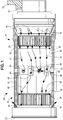
FIG. 1 is a part cross-sectional, side view of an embodiment of a power transmission device; -
FIG. 2 is a fragmentary, isometric, cross-sectional view of the embodiment the power transmission device ofFIG. 1 ; and -
FIG. 3 is a fragmentary, cross-sectional, side view of the embodiment of the power transmission device ofFIG. 1 . - As shown herein a power transmission device is provided that utilizes a quill shaft having an obliquely angled ejector orifice and a raised boss with an aperture that eject a lubricating fluid from the inside to the outside of the quill shaft. The fluid is also for cooling the inside elements of the power transmission device. The fluid, for example, may be oil or other type of fluid known to those skilled in the art. The power transmission device in this embodiment provides for the control of flowrate and the volume of the oil within the power transmission device and achieves a desired cooling and lubrication of the inside elements such as the splines and their associated teeth that engage with the splines of the drive system and the driven component. The lubrication and cooling of the splines and the teeth thereof extend the life of the mechanically engaged devices. The present embodiment also provides for a single-end capture and a single-end feed of the oil through the power transmission device.
- Referring to
FIG. 1 , an embodiment of thepower transmission device 10 is shown having aquill shaft 12 with afirst end 14 and asecond end 16. A first shaft in a form of adrive shaft 18 is engaged with thefirst end 14, and a second shaft for example, of a compressor (not shown) in a form of aload shaft 20 is engaged with thesecond end 16. Asump injector 22 delivers oil 24 (shown as arrows) via feed-through holes in a form ofinjection orifices 26 formed through thedrive shaft 18 to the inside of thequill shaft 12. Thedrive shaft 18 has driveshaft splines 28, which engageteeth 30 offirst splines 32 on thequill shaft 12. Similarly, theload shaft 20 hasload shaft splines 34, which engageteeth 36 ofsecond splines 38 on thequill shaft 12 located at thesecond end 16. As seen inFIGS. 2 and3 , theoil 24 flows through interface surfaces between theteeth 30 and thedrive shaft spline 28 and into anintermediate portion 40 of thequill shaft 12. Theoil 24 accumulates within theintermediate portion 40 against theinside wall 42 of thequill shaft 12 because of the centrifugal force of thequill shaft 12 when spinning and in operation. The accumulatedoil 24 continues to flow past one or more raisedbosses 44 viachannels 46 that are formed between the raisedbosses 44. As shown inFIG. 3 , some of theoil 24 traverse interface surfaces between theteeth 36 and the load shaft splines 34. Eventually, some of theoil 24 is ejected to the outside of thequill shaft 12 through one ormore ejector orifices 48. The rest of the oil that has accumulated within theintermediate portion 40 is ejected out ofapertures 50 formed in the raisedbosses 44 to the outside of thequill shaft 12. - Referring to
FIG. 2 , a fragmentary, isometric, cross-sectional view of the examplepower transmission device 10 illustrates the flow of receivedoil 24 at thefirst end 14 of thequill shaft 12 and through various portions of thequill shaft 12 until ejection of theoil 24 from theejector orifices 48 and theapertures 50.Oil 24 is received through theinjection orifices 26, which are formed by anadapter 52 disposed between theinside wall 42 of thequill shaft 12 and thedrive shaft 18. Because of the centrifugal force of the spinningdrive shaft 18, theoil 24 is then directed toward aningress oil cavity 54. Theingress oil cavity 54 is formed between thedrive shaft 18 and theinside wall 42 of thequill shaft 12. Once the oil fills theingress cavity 54, it then flows in an axial direction between theteeth 30 and the drive shaft splines 28. As theoil 24 flows into theintermediate portion 40, it keeps flowing past the raisedbosses 44 throughchannels 46 and between the load shaft splines 34 andteeth 36 at thesecond end 16 of thequill shaft 12. Theoil 24 wets and lubricates theteeth 36 and load shaft splines 34. Theoil 24 reaches and pours into anegress oil cavity 56. After filling theegress oil cavity 54, theoil 24 is ejected to the outside of thequill shaft 12 through theejector orifices 48, which are arranged circumferentially around thequill shaft 12. - The ejector orifices 48 by virtue of being obliquely angled provide a resistance to the flow of
oil 24 therethrough such that the amount and flowrate of the ejectedoil 24 is metered. The ejector orifices 48 are preferably obliquely angled toward thefirst end 14 of thequill shaft 12. The flow resistance provided by theejector orifices 48 are such that the flowrate ofoil 24 is neither too fast nor too slow. More specifically, if theoil 24 flowrate is too fast, there would be too much oil wasted and also there would not be a sufficient volume ofoil 24 accumulated or pooled up against theinside wall 42 of the quill shaft to ensure that theteeth oil 24 flowrate is too slow, then theoil 24 will become stagnant within thequill shaft 12. This can result in higher temperatures for theteeth splines quill shaft 12,drive shaft 18, andload shaft 20. It should be noted that a size of opening of theejector orifices 48 and the oblique angle of theejector orifices 48 are predetermined based on the oil characteristics that is received in thepower transmission device 10. The oil characteristics include, among others, the type and grade of oil, the amount and type of debris particles present in the oil, and any other elements/features that define the oil characteristics. Furthermore, the total number ofejector orifices 48 are determined based on the acuteness of the oblique angle of theejector orifices 48 with respect to thequill shaft 12 as well as the size of the openings of theejector orifices 48. Also, when a larger number ofejector orifices 48 are employed, the probability of having too manyejector orifices 48 plugged up with debris over an extended operation of thepower transmission device 10 is decreased, thereby less frequent maintenance and service would be needed. - The raised
bosses 44 have a height H as shown by the two-facing arrows. This height H determines a level to which theoil 24 must rise by pooling up against theinside wall 42 of thequill shaft 12 until it can flow out of theapertures 50. The height H should be at least at a level that the risen pooled upoil 24 can wet a sufficient portion of theteeth splines oil 24 is ejected out of theapertures 50, any heat generated during the operation of thepower transmission device 10 is transferred away by the flowingoil 24. In some circumstances, the height H may be larger than height of theteeth splines teeth splines oil 24 during operation. The height H of the raisedbosses 44 determines the volume of theoil 24 that can pool up within the quill shaft before any excess amount ofoil 24 is ejected from theapertures 50. A determination of an optimum volume/amount of theoil 24 is also influenced by the design limitations of thepower transmission device 10 in so far as not compromising the device balance beyond analyzed limits during operation. - Referring to
FIG. 3 ,injection orifices 26 haveingress apertures 58 whereoil 24 is received therein. Thesump injector 22 injectsoil 24 at a desired angle towards theingress apertures 58 at which point the injectedoil 24 is deflected and propelled into the injection orifices 26. The rotational velocity of thedrive shaft 18 slings theoil 24 through theinjection orifices 26 and against theinside wall 42. A level of theingress aperture 58 is non-coplanar with a plane defined by atop surface 60 of the raisedbosses 44. Preferably the level of theingress apertures 58 is at a height, i.e., a distance relative to theinside wall 42, that is higher than the height H of the plane of thetop surface 60 of the raisedbosses 44 such that when theoil 24 is pooled up within thequill shaft 12 there would not be a backflow of theoil 24 out of theingress apertures 58. The injector orifices 26 are obliquely angled from theingress apertures 58 toward thequill shaft 12. - The
ingress oil cavity 54 is sealed on one end with an O-ring 62, so that theoil 24 is forced in one direction through the teeth 30 (also referred to as working splines). As described hereinabove, theoil 24 flows downstream until it is ejected through theejector orifices 48. A downstream O-ring 64 prevents leaking of theoil 24 from an interface between thequill shaft 12 and theload shaft 20. The downstream O-ring 64 permits theoil 24 to accumulate in theegress oil cavity 56 before it is ejected through theejector orifices 48. - The design options for the
power transmission device 10 utilizing aquill shaft 12 having the fluid/oil delivery mechanism as described herein are not limited to any specific application and/or a specific fluid source. - As provided herein, the power transmission device may be employed in connection with a compressor, and more specifically a compressor intended to be used in a gas turbine engine. The use of the terms "a" and "an" and "the" and similar references in the context of describing the invention (especially in the context of the following claims) are to be construed to cover both the singular and the plural, unless otherwise indicated herein or clearly contradicted by context. Recitation of ranges of values herein are merely intended to serve as a shorthand method of referring individually to each separate value falling within the range, unless otherwise indicated herein, and each separate value is incorporated into the specification as if it were individually recited herein. All methods described herein can be performed in any suitable order unless otherwise indicated herein or otherwise clearly contradicted by context. The use of any and all examples, or exemplary language (e.g., "such as") provided herein, is intended merely to better illuminate the disclosure and does not pose a limitation on the scope of the disclosure unless otherwise claimed. No language in the specification should be construed as indicating any non-claimed element as essential to the practice of the disclosure.
- Numerous modifications to the present disclosure will be apparent to those skilled in the art in view of the foregoing description. It should be understood that the illustrated embodiments are exemplary only, and should not be taken as limiting the scope of the disclosure.
Claims (10)
- A power transmission device, comprising:a quill shaft having a first end and a second end;a first shaft engaged with the first end of the quill shaft;a second shaft engaged with the second end of the quill shaft; anda raised boss on an interior surface of the quill shaft having an aperture therein, wherein the raised boss is adapted to eject a fluid through the aperture to outside of the quill shaft.
- The power transmission device claimed in claim 1, wherein the quill shaft further comprises:a first plurality of splines at the first end engaged with the first shaft; anda second plurality of splines at the second end engaged with the second shaft, wherein each of the first and second plurality of splines have teeth.
- The power transmission device claimed in claim 1 or claim 2, wherein the raised boss has a height such that the fluid flowing within the quill shaft pools up to a level of a top surface of the raised boss, whereby the fluid contacts the teeth of the first and second plurality of splines.
- The power transmission device claimed in any preceding claim, wherein the fluid is oil and further comprising:
an injection orifice adapted to receive the oil therethrough. - The power transmission device claimed in claim 4, wherein the injection orifice is formed by an adapter disposed between the first shaft and the quill shaft.
- The power transmission device claimed in claim 4 or claim 5, wherein the injection orifice has an ingress aperture that is non-coplanar with a plane defined by a top surface of the raised boss.
- The power transmission device claimed in any preceding claim, further comprising:
an ejector orifice at the second end of the quill shaft distal from the first shaft, wherein the ejector orifice forms an oblique angle with respect to the quill shaft, and wherein the ejector orifice is adapted to eject the oil therethrough. - The power transmission device claimed in any preceding claim, further comprising:a driver member coupled to the first shaft; anda load member coupled to the second shaft, wherein power is transmitted from the driver member through the quill shaft to the load member.
- The power transmission device claimed in any one of claims 6 to 8, wherein the quill shaft further comprises:a first plurality of splines at the first end engaged with the first shaft; anda second plurality of splines at the second end engaged with the second shaft, wherein each of the first and second plurality of splines have teeth, wherein the injection orifice is obliquely angled from the ingress aperture toward the quill shaft such that the received oil is directed into the quill shaft, whereby the teeth of the quill shaft are wetted with the received oil.
- The power transmission device claimed in any one of claims 7 to 9, wherein the ejector orifice angles toward the first end of the quill shaft, and wherein a size of an opening of the ejector orifice and the oblique angle are predetermined based on characteristics of the oil.
Applications Claiming Priority (2)
| Application Number | Priority Date | Filing Date | Title |
|---|---|---|---|
| US14/921,561 US10801551B2 (en) | 2015-10-23 | 2015-10-23 | Power transmission device |
| EP16194309.7A EP3159511B1 (en) | 2015-10-23 | 2016-10-18 | Power transmission device |
Related Parent Applications (2)
| Application Number | Title | Priority Date | Filing Date |
|---|---|---|---|
| EP16194309.7A Division EP3159511B1 (en) | 2015-10-23 | 2016-10-18 | Power transmission device |
| EP16194309.7A Division-Into EP3159511B1 (en) | 2015-10-23 | 2016-10-18 | Power transmission device |
Publications (2)
| Publication Number | Publication Date |
|---|---|
| EP3456941A1 true EP3456941A1 (en) | 2019-03-20 |
| EP3456941B1 EP3456941B1 (en) | 2021-02-03 |
Family
ID=57189807
Family Applications (2)
| Application Number | Title | Priority Date | Filing Date |
|---|---|---|---|
| EP18203821.6A Active EP3456941B1 (en) | 2015-10-23 | 2016-10-18 | Power transmission device |
| EP16194309.7A Active EP3159511B1 (en) | 2015-10-23 | 2016-10-18 | Power transmission device |
Family Applications After (1)
| Application Number | Title | Priority Date | Filing Date |
|---|---|---|---|
| EP16194309.7A Active EP3159511B1 (en) | 2015-10-23 | 2016-10-18 | Power transmission device |
Country Status (3)
| Country | Link |
|---|---|
| US (1) | US10801551B2 (en) |
| EP (2) | EP3456941B1 (en) |
| CA (1) | CA2943971A1 (en) |
Families Citing this family (6)
| Publication number | Priority date | Publication date | Assignee | Title |
|---|---|---|---|---|
| CN110953303A (en) * | 2018-09-27 | 2020-04-03 | 南京高速齿轮制造有限公司 | Gear box for wind driven generator |
| JP7443898B2 (en) * | 2020-04-03 | 2024-03-06 | スズキ株式会社 | power transmission device |
| DE102020113592A1 (en) * | 2020-05-19 | 2021-11-25 | Bayerische Motoren Werke Aktiengesellschaft | Hollow shaft arrangement for a motor vehicle |
| CN112576635B (en) * | 2020-11-18 | 2021-12-14 | 合肥通用机械研究院有限公司 | Middle section with active cooling function and heat-insulating coupling with same |
| GB2635112A (en) * | 2023-10-23 | 2025-05-07 | Rolls Royce Deutschland Ltd & Co Kg | Shaft system and method for assembling a shaft system |
| US12535183B2 (en) * | 2024-01-19 | 2026-01-27 | Pratt & Whitney Canada Corp. | Fluid flow metering device for aircraft shaft(s) |
Citations (2)
| Publication number | Priority date | Publication date | Assignee | Title |
|---|---|---|---|---|
| US3889489A (en) * | 1974-08-23 | 1975-06-17 | Gen Motors Corp | Lubricated spline coupling |
| US20090159370A1 (en) * | 2007-12-20 | 2009-06-25 | Rolls-Royce Corporation | Dual splined shaft |
Family Cites Families (9)
| Publication number | Priority date | Publication date | Assignee | Title |
|---|---|---|---|---|
| US2712967A (en) | 1953-02-06 | 1955-07-12 | Rolls Royce | Lubricating arrangements for rotating parts |
| US2926755A (en) | 1958-07-17 | 1960-03-01 | Gen Motors Corp | Gear lubricating mechanism |
| US3038556A (en) | 1959-10-22 | 1962-06-12 | Gen Electric | Internal lubrication tube structure for hollow shafts |
| US3667214A (en) | 1970-03-11 | 1972-06-06 | Gen Motors Corp | Engine turbosupercharger with vibration reducing drive |
| US4047602A (en) | 1975-12-11 | 1977-09-13 | Dynetics, Inc. | Synchronizing coupling |
| US4201271A (en) | 1978-07-10 | 1980-05-06 | Larry Evans | Quill drive with variable feed |
| US4567784A (en) | 1983-03-31 | 1986-02-04 | Dresser Industries, Inc. | Method and apparatus for lubricating a transmission |
| US8789656B2 (en) | 2011-10-31 | 2014-07-29 | Honeywell International Inc. | Shaft bearing lubricant aerator, system, and method |
| WO2014165138A1 (en) * | 2013-03-13 | 2014-10-09 | United Technologies Corporation | Oil transfer passage arrangement for a shaft of a gas turbine engine |
-
2015
- 2015-10-23 US US14/921,561 patent/US10801551B2/en active Active
-
2016
- 2016-09-30 CA CA2943971A patent/CA2943971A1/en not_active Abandoned
- 2016-10-18 EP EP18203821.6A patent/EP3456941B1/en active Active
- 2016-10-18 EP EP16194309.7A patent/EP3159511B1/en active Active
Patent Citations (2)
| Publication number | Priority date | Publication date | Assignee | Title |
|---|---|---|---|---|
| US3889489A (en) * | 1974-08-23 | 1975-06-17 | Gen Motors Corp | Lubricated spline coupling |
| US20090159370A1 (en) * | 2007-12-20 | 2009-06-25 | Rolls-Royce Corporation | Dual splined shaft |
Also Published As
| Publication number | Publication date |
|---|---|
| EP3159511A1 (en) | 2017-04-26 |
| US10801551B2 (en) | 2020-10-13 |
| CA2943971A1 (en) | 2017-04-23 |
| EP3456941B1 (en) | 2021-02-03 |
| EP3159511B1 (en) | 2019-01-02 |
| US20170114835A1 (en) | 2017-04-27 |
Similar Documents
| Publication | Publication Date | Title |
|---|---|---|
| EP3456941B1 (en) | Power transmission device | |
| US8678937B2 (en) | Shaft coupling | |
| US10451169B2 (en) | Dual splined shaft | |
| US9091305B2 (en) | Clutch assembly with oil guide | |
| EP3043091B1 (en) | Shaft coupling seal assembly | |
| EP3098480B1 (en) | Gear shroud to passively lubricate gearbox component | |
| WO2009034781A1 (en) | Power unit | |
| CN110848374B (en) | Hybrid transmission | |
| CN119278332A (en) | Vehicle powertrain component with lubricating degasser | |
| US20090036249A1 (en) | Flywheel having lubrication-flow passageway | |
| CN115362320B (en) | Hollow shaft arrangement for a motor vehicle | |
| JP2003120894A (en) | Bearing lubrication structure for rotating shaft | |
| US6575709B2 (en) | Pumps | |
| KR101511879B1 (en) | Housing with a direct flow path for hardware lubrication | |
| US9157444B2 (en) | Supercharger transmission | |
| CN111852875B (en) | Scavenging centrifugal baffle pump | |
| CN113513575B (en) | Spline connection lubricating structure | |
| CN211145311U (en) | Lubricating and cooling structure for high-power durability test of gear | |
| US10385962B2 (en) | Direct lubricating input shaft assembly | |
| KR20100029525A (en) | Lubrication structure | |
| US20110263341A1 (en) | Transmission input shaft blade | |
| JP2017003060A (en) | Automatic transmission |
Legal Events
| Date | Code | Title | Description |
|---|---|---|---|
| PUAI | Public reference made under article 153(3) epc to a published international application that has entered the european phase |
Free format text: ORIGINAL CODE: 0009012 |
|
| STAA | Information on the status of an ep patent application or granted ep patent |
Free format text: STATUS: THE APPLICATION HAS BEEN PUBLISHED |
|
| AC | Divisional application: reference to earlier application |
Ref document number: 3159511 Country of ref document: EP Kind code of ref document: P |
|
| AK | Designated contracting states |
Kind code of ref document: A1 Designated state(s): AL AT BE BG CH CY CZ DE DK EE ES FI FR GB GR HR HU IE IS IT LI LT LU LV MC MK MT NL NO PL PT RO RS SE SI SK SM TR |
|
| STAA | Information on the status of an ep patent application or granted ep patent |
Free format text: STATUS: REQUEST FOR EXAMINATION WAS MADE |
|
| 17P | Request for examination filed |
Effective date: 20190917 |
|
| RBV | Designated contracting states (corrected) |
Designated state(s): AL AT BE BG CH CY CZ DE DK EE ES FI FR GB GR HR HU IE IS IT LI LT LU LV MC MK MT NL NO PL PT RO RS SE SI SK SM TR |
|
| STAA | Information on the status of an ep patent application or granted ep patent |
Free format text: STATUS: EXAMINATION IS IN PROGRESS |
|
| 17Q | First examination report despatched |
Effective date: 20200316 |
|
| GRAP | Despatch of communication of intention to grant a patent |
Free format text: ORIGINAL CODE: EPIDOSNIGR1 |
|
| STAA | Information on the status of an ep patent application or granted ep patent |
Free format text: STATUS: GRANT OF PATENT IS INTENDED |
|
| INTG | Intention to grant announced |
Effective date: 20201016 |
|
| GRAS | Grant fee paid |
Free format text: ORIGINAL CODE: EPIDOSNIGR3 |
|
| GRAA | (expected) grant |
Free format text: ORIGINAL CODE: 0009210 |
|
| STAA | Information on the status of an ep patent application or granted ep patent |
Free format text: STATUS: THE PATENT HAS BEEN GRANTED |
|
| AC | Divisional application: reference to earlier application |
Ref document number: 3159511 Country of ref document: EP Kind code of ref document: P |
|
| AK | Designated contracting states |
Kind code of ref document: B1 Designated state(s): AL AT BE BG CH CY CZ DE DK EE ES FI FR GB GR HR HU IE IS IT LI LT LU LV MC MK MT NL NO PL PT RO RS SE SI SK SM TR |
|
| REG | Reference to a national code |
Ref country code: GB Ref legal event code: FG4D |
|
| REG | Reference to a national code |
Ref country code: AT Ref legal event code: REF Ref document number: 1359746 Country of ref document: AT Kind code of ref document: T Effective date: 20210215 Ref country code: CH Ref legal event code: EP |
|
| REG | Reference to a national code |
Ref country code: DE Ref legal event code: R096 Ref document number: 602016052415 Country of ref document: DE |
|
| REG | Reference to a national code |
Ref country code: IE Ref legal event code: FG4D |
|
| REG | Reference to a national code |
Ref country code: NL Ref legal event code: MP Effective date: 20210203 |
|
| REG | Reference to a national code |
Ref country code: LT Ref legal event code: MG9D |
|
| REG | Reference to a national code |
Ref country code: AT Ref legal event code: MK05 Ref document number: 1359746 Country of ref document: AT Kind code of ref document: T Effective date: 20210203 |
|
| PG25 | Lapsed in a contracting state [announced via postgrant information from national office to epo] |
Ref country code: LT Free format text: LAPSE BECAUSE OF FAILURE TO SUBMIT A TRANSLATION OF THE DESCRIPTION OR TO PAY THE FEE WITHIN THE PRESCRIBED TIME-LIMIT Effective date: 20210203 Ref country code: NO Free format text: LAPSE BECAUSE OF FAILURE TO SUBMIT A TRANSLATION OF THE DESCRIPTION OR TO PAY THE FEE WITHIN THE PRESCRIBED TIME-LIMIT Effective date: 20210503 Ref country code: PT Free format text: LAPSE BECAUSE OF FAILURE TO SUBMIT A TRANSLATION OF THE DESCRIPTION OR TO PAY THE FEE WITHIN THE PRESCRIBED TIME-LIMIT Effective date: 20210604 Ref country code: BG Free format text: LAPSE BECAUSE OF FAILURE TO SUBMIT A TRANSLATION OF THE DESCRIPTION OR TO PAY THE FEE WITHIN THE PRESCRIBED TIME-LIMIT Effective date: 20210503 Ref country code: FI Free format text: LAPSE BECAUSE OF FAILURE TO SUBMIT A TRANSLATION OF THE DESCRIPTION OR TO PAY THE FEE WITHIN THE PRESCRIBED TIME-LIMIT Effective date: 20210203 Ref country code: GR Free format text: LAPSE BECAUSE OF FAILURE TO SUBMIT A TRANSLATION OF THE DESCRIPTION OR TO PAY THE FEE WITHIN THE PRESCRIBED TIME-LIMIT Effective date: 20210504 Ref country code: HR Free format text: LAPSE BECAUSE OF FAILURE TO SUBMIT A TRANSLATION OF THE DESCRIPTION OR TO PAY THE FEE WITHIN THE PRESCRIBED TIME-LIMIT Effective date: 20210203 |
|
| PG25 | Lapsed in a contracting state [announced via postgrant information from national office to epo] |
Ref country code: RS Free format text: LAPSE BECAUSE OF FAILURE TO SUBMIT A TRANSLATION OF THE DESCRIPTION OR TO PAY THE FEE WITHIN THE PRESCRIBED TIME-LIMIT Effective date: 20210203 Ref country code: LV Free format text: LAPSE BECAUSE OF FAILURE TO SUBMIT A TRANSLATION OF THE DESCRIPTION OR TO PAY THE FEE WITHIN THE PRESCRIBED TIME-LIMIT Effective date: 20210203 Ref country code: PL Free format text: LAPSE BECAUSE OF FAILURE TO SUBMIT A TRANSLATION OF THE DESCRIPTION OR TO PAY THE FEE WITHIN THE PRESCRIBED TIME-LIMIT Effective date: 20210203 Ref country code: NL Free format text: LAPSE BECAUSE OF FAILURE TO SUBMIT A TRANSLATION OF THE DESCRIPTION OR TO PAY THE FEE WITHIN THE PRESCRIBED TIME-LIMIT Effective date: 20210203 Ref country code: AT Free format text: LAPSE BECAUSE OF FAILURE TO SUBMIT A TRANSLATION OF THE DESCRIPTION OR TO PAY THE FEE WITHIN THE PRESCRIBED TIME-LIMIT Effective date: 20210203 Ref country code: SE Free format text: LAPSE BECAUSE OF FAILURE TO SUBMIT A TRANSLATION OF THE DESCRIPTION OR TO PAY THE FEE WITHIN THE PRESCRIBED TIME-LIMIT Effective date: 20210203 |
|
| PG25 | Lapsed in a contracting state [announced via postgrant information from national office to epo] |
Ref country code: IS Free format text: LAPSE BECAUSE OF FAILURE TO SUBMIT A TRANSLATION OF THE DESCRIPTION OR TO PAY THE FEE WITHIN THE PRESCRIBED TIME-LIMIT Effective date: 20210603 |
|
| PG25 | Lapsed in a contracting state [announced via postgrant information from national office to epo] |
Ref country code: SM Free format text: LAPSE BECAUSE OF FAILURE TO SUBMIT A TRANSLATION OF THE DESCRIPTION OR TO PAY THE FEE WITHIN THE PRESCRIBED TIME-LIMIT Effective date: 20210203 Ref country code: EE Free format text: LAPSE BECAUSE OF FAILURE TO SUBMIT A TRANSLATION OF THE DESCRIPTION OR TO PAY THE FEE WITHIN THE PRESCRIBED TIME-LIMIT Effective date: 20210203 Ref country code: CZ Free format text: LAPSE BECAUSE OF FAILURE TO SUBMIT A TRANSLATION OF THE DESCRIPTION OR TO PAY THE FEE WITHIN THE PRESCRIBED TIME-LIMIT Effective date: 20210203 |
|
| REG | Reference to a national code |
Ref country code: DE Ref legal event code: R097 Ref document number: 602016052415 Country of ref document: DE |
|
| PG25 | Lapsed in a contracting state [announced via postgrant information from national office to epo] |
Ref country code: DK Free format text: LAPSE BECAUSE OF FAILURE TO SUBMIT A TRANSLATION OF THE DESCRIPTION OR TO PAY THE FEE WITHIN THE PRESCRIBED TIME-LIMIT Effective date: 20210203 Ref country code: SK Free format text: LAPSE BECAUSE OF FAILURE TO SUBMIT A TRANSLATION OF THE DESCRIPTION OR TO PAY THE FEE WITHIN THE PRESCRIBED TIME-LIMIT Effective date: 20210203 Ref country code: RO Free format text: LAPSE BECAUSE OF FAILURE TO SUBMIT A TRANSLATION OF THE DESCRIPTION OR TO PAY THE FEE WITHIN THE PRESCRIBED TIME-LIMIT Effective date: 20210203 |
|
| PLBE | No opposition filed within time limit |
Free format text: ORIGINAL CODE: 0009261 |
|
| STAA | Information on the status of an ep patent application or granted ep patent |
Free format text: STATUS: NO OPPOSITION FILED WITHIN TIME LIMIT |
|
| 26N | No opposition filed |
Effective date: 20211104 |
|
| PG25 | Lapsed in a contracting state [announced via postgrant information from national office to epo] |
Ref country code: ES Free format text: LAPSE BECAUSE OF FAILURE TO SUBMIT A TRANSLATION OF THE DESCRIPTION OR TO PAY THE FEE WITHIN THE PRESCRIBED TIME-LIMIT Effective date: 20210203 Ref country code: AL Free format text: LAPSE BECAUSE OF FAILURE TO SUBMIT A TRANSLATION OF THE DESCRIPTION OR TO PAY THE FEE WITHIN THE PRESCRIBED TIME-LIMIT Effective date: 20210203 |
|
| PG25 | Lapsed in a contracting state [announced via postgrant information from national office to epo] |
Ref country code: SI Free format text: LAPSE BECAUSE OF FAILURE TO SUBMIT A TRANSLATION OF THE DESCRIPTION OR TO PAY THE FEE WITHIN THE PRESCRIBED TIME-LIMIT Effective date: 20210203 |
|
| PG25 | Lapsed in a contracting state [announced via postgrant information from national office to epo] |
Ref country code: IT Free format text: LAPSE BECAUSE OF FAILURE TO SUBMIT A TRANSLATION OF THE DESCRIPTION OR TO PAY THE FEE WITHIN THE PRESCRIBED TIME-LIMIT Effective date: 20210203 |
|
| REG | Reference to a national code |
Ref country code: DE Ref legal event code: R119 Ref document number: 602016052415 Country of ref document: DE |
|
| REG | Reference to a national code |
Ref country code: CH Ref legal event code: PL |
|
| PG25 | Lapsed in a contracting state [announced via postgrant information from national office to epo] |
Ref country code: IS Free format text: LAPSE BECAUSE OF FAILURE TO SUBMIT A TRANSLATION OF THE DESCRIPTION OR TO PAY THE FEE WITHIN THE PRESCRIBED TIME-LIMIT Effective date: 20210603 |
|
| REG | Reference to a national code |
Ref country code: BE Ref legal event code: MM Effective date: 20211031 |
|
| GBPC | Gb: european patent ceased through non-payment of renewal fee |
Effective date: 20211018 |
|
| PG25 | Lapsed in a contracting state [announced via postgrant information from national office to epo] |
Ref country code: MC Free format text: LAPSE BECAUSE OF FAILURE TO SUBMIT A TRANSLATION OF THE DESCRIPTION OR TO PAY THE FEE WITHIN THE PRESCRIBED TIME-LIMIT Effective date: 20210203 |
|
| PG25 | Lapsed in a contracting state [announced via postgrant information from national office to epo] |
Ref country code: LU Free format text: LAPSE BECAUSE OF NON-PAYMENT OF DUE FEES Effective date: 20211018 Ref country code: GB Free format text: LAPSE BECAUSE OF NON-PAYMENT OF DUE FEES Effective date: 20211018 Ref country code: DE Free format text: LAPSE BECAUSE OF NON-PAYMENT OF DUE FEES Effective date: 20220503 Ref country code: BE Free format text: LAPSE BECAUSE OF NON-PAYMENT OF DUE FEES Effective date: 20211031 |
|
| PG25 | Lapsed in a contracting state [announced via postgrant information from national office to epo] |
Ref country code: LI Free format text: LAPSE BECAUSE OF NON-PAYMENT OF DUE FEES Effective date: 20211031 Ref country code: CH Free format text: LAPSE BECAUSE OF NON-PAYMENT OF DUE FEES Effective date: 20211031 |
|
| PG25 | Lapsed in a contracting state [announced via postgrant information from national office to epo] |
Ref country code: IE Free format text: LAPSE BECAUSE OF NON-PAYMENT OF DUE FEES Effective date: 20211018 |
|
| PG25 | Lapsed in a contracting state [announced via postgrant information from national office to epo] |
Ref country code: CY Free format text: LAPSE BECAUSE OF FAILURE TO SUBMIT A TRANSLATION OF THE DESCRIPTION OR TO PAY THE FEE WITHIN THE PRESCRIBED TIME-LIMIT Effective date: 20210203 |
|
| P01 | Opt-out of the competence of the unified patent court (upc) registered |
Effective date: 20230528 |
|
| PG25 | Lapsed in a contracting state [announced via postgrant information from national office to epo] |
Ref country code: HU Free format text: LAPSE BECAUSE OF FAILURE TO SUBMIT A TRANSLATION OF THE DESCRIPTION OR TO PAY THE FEE WITHIN THE PRESCRIBED TIME-LIMIT; INVALID AB INITIO Effective date: 20161018 |
|
| PG25 | Lapsed in a contracting state [announced via postgrant information from national office to epo] |
Ref country code: MK Free format text: LAPSE BECAUSE OF FAILURE TO SUBMIT A TRANSLATION OF THE DESCRIPTION OR TO PAY THE FEE WITHIN THE PRESCRIBED TIME-LIMIT Effective date: 20210203 |
|
| PG25 | Lapsed in a contracting state [announced via postgrant information from national office to epo] |
Ref country code: TR Free format text: LAPSE BECAUSE OF FAILURE TO SUBMIT A TRANSLATION OF THE DESCRIPTION OR TO PAY THE FEE WITHIN THE PRESCRIBED TIME-LIMIT Effective date: 20210203 |
|
| PG25 | Lapsed in a contracting state [announced via postgrant information from national office to epo] |
Ref country code: MT Free format text: LAPSE BECAUSE OF FAILURE TO SUBMIT A TRANSLATION OF THE DESCRIPTION OR TO PAY THE FEE WITHIN THE PRESCRIBED TIME-LIMIT Effective date: 20210203 |
|
| PGFP | Annual fee paid to national office [announced via postgrant information from national office to epo] |
Ref country code: FR Payment date: 20251027 Year of fee payment: 10 |