EP3456596A1 - Method and device of predicting a possible collision - Google Patents
Method and device of predicting a possible collision Download PDFInfo
- Publication number
- EP3456596A1 EP3456596A1 EP17465548.0A EP17465548A EP3456596A1 EP 3456596 A1 EP3456596 A1 EP 3456596A1 EP 17465548 A EP17465548 A EP 17465548A EP 3456596 A1 EP3456596 A1 EP 3456596A1
- Authority
- EP
- European Patent Office
- Prior art keywords
- ego vehicle
- target
- path
- computed
- core path
- Prior art date
- Legal status (The legal status is an assumption and is not a legal conclusion. Google has not performed a legal analysis and makes no representation as to the accuracy of the status listed.)
- Withdrawn
Links
Images



Classifications
-
- B—PERFORMING OPERATIONS; TRANSPORTING
- B60—VEHICLES IN GENERAL
- B60W—CONJOINT CONTROL OF VEHICLE SUB-UNITS OF DIFFERENT TYPE OR DIFFERENT FUNCTION; CONTROL SYSTEMS SPECIALLY ADAPTED FOR HYBRID VEHICLES; ROAD VEHICLE DRIVE CONTROL SYSTEMS FOR PURPOSES NOT RELATED TO THE CONTROL OF A PARTICULAR SUB-UNIT
- B60W30/00—Purposes of road vehicle drive control systems not related to the control of a particular sub-unit, e.g. of systems using conjoint control of vehicle sub-units
- B60W30/08—Active safety systems predicting or avoiding probable or impending collision or attempting to minimise its consequences
- B60W30/095—Predicting travel path or likelihood of collision
-
- B—PERFORMING OPERATIONS; TRANSPORTING
- B60—VEHICLES IN GENERAL
- B60W—CONJOINT CONTROL OF VEHICLE SUB-UNITS OF DIFFERENT TYPE OR DIFFERENT FUNCTION; CONTROL SYSTEMS SPECIALLY ADAPTED FOR HYBRID VEHICLES; ROAD VEHICLE DRIVE CONTROL SYSTEMS FOR PURPOSES NOT RELATED TO THE CONTROL OF A PARTICULAR SUB-UNIT
- B60W2540/00—Input parameters relating to occupants
- B60W2540/18—Steering angle
-
- B—PERFORMING OPERATIONS; TRANSPORTING
- B60—VEHICLES IN GENERAL
- B60W—CONJOINT CONTROL OF VEHICLE SUB-UNITS OF DIFFERENT TYPE OR DIFFERENT FUNCTION; CONTROL SYSTEMS SPECIALLY ADAPTED FOR HYBRID VEHICLES; ROAD VEHICLE DRIVE CONTROL SYSTEMS FOR PURPOSES NOT RELATED TO THE CONTROL OF A PARTICULAR SUB-UNIT
- B60W2554/00—Input parameters relating to objects
-
- B—PERFORMING OPERATIONS; TRANSPORTING
- B60—VEHICLES IN GENERAL
- B60W—CONJOINT CONTROL OF VEHICLE SUB-UNITS OF DIFFERENT TYPE OR DIFFERENT FUNCTION; CONTROL SYSTEMS SPECIALLY ADAPTED FOR HYBRID VEHICLES; ROAD VEHICLE DRIVE CONTROL SYSTEMS FOR PURPOSES NOT RELATED TO THE CONTROL OF A PARTICULAR SUB-UNIT
- B60W2554/00—Input parameters relating to objects
- B60W2554/40—Dynamic objects, e.g. animals, windblown objects
- B60W2554/404—Characteristics
- B60W2554/4044—Direction of movement, e.g. backwards
-
- B—PERFORMING OPERATIONS; TRANSPORTING
- B60—VEHICLES IN GENERAL
- B60W—CONJOINT CONTROL OF VEHICLE SUB-UNITS OF DIFFERENT TYPE OR DIFFERENT FUNCTION; CONTROL SYSTEMS SPECIALLY ADAPTED FOR HYBRID VEHICLES; ROAD VEHICLE DRIVE CONTROL SYSTEMS FOR PURPOSES NOT RELATED TO THE CONTROL OF A PARTICULAR SUB-UNIT
- B60W2554/00—Input parameters relating to objects
- B60W2554/80—Spatial relation or speed relative to objects
Definitions
- the invention refers to a method and device of predicting a possible collision of a vehicle with an oncoming moving object, intended mainly for mitigate lateral collision.
- radar sensors are used in order to increase the safety of the cars, either by alerting the driver of an important danger or by triggering autonomous reactions, which can involve braking or steering the car, in case of imminent collisions.
- Short-range radars endowed with large field of views, are mounted on a car's corners monitor large areas around the car and can be used in order to predict probable lateral collisions with other cars.
- Functions that alert the user about such probable collisions are already in use in passenger cars, but often they consider straight, linear trajectories to predict an intersection point, which may be sufficient for driver alert functions, for low driving speeds, or when the host vehicle is standing, but which can cause issues for more important decisions, like having to automatically brake or to steer the car in order to increase the safety of passengers.
- Patent US8060306B2 discloses a method and system for avoiding an obstacle.
- the system comprises a mapping module or path filtering module which is arranged to identify admissible curved paths for which the vehicle is able to stop prior to reaching a detected obstacle in accordance with an observed translational velocity and an observed rotational velocity.
- a data processor determines a respective objective function for the candidate translational velocities and candidate rotational velocities associated with the admissible curved paths, where the objective function includes a curvature comparison term associated with the last curved path of the vehicle.
- a search engine or data processor selects preferential velocities, among the candidate translational velocities and candidate rotational velocities, with a superior value for its corresponding objective function, and the path planning module or data processor determines the vehicular speed and trajectory for a path plan that avoids the obstacle consistent with the selected preferential velocities.
- the invention takes into consideration the subject vehicle's path as a series of admissible curved paths, but it concerns only the case of a possible collision with a static obstacle, not a moving one.
- Another patent document, US 5841366 discloses a traveling-path deduction apparatus and method.
- the said method is able to detect objects existing ahead of the vehicle and to deduce a temporary traveling path of the vehicle and to set the traveling path having the minimum time change amount in the distances. It is said that in case of a properly-set temporary traveling path, the path and running loci of the preceding vehicles are on a concentric circle.
- having to compute a plurality of temporary traveling paths with different curvatures requires a lot of computing resources, when the preceding vehicle (or the vehicle ahead) does not follow a straight trajectory.
- the object of the invention is to indicate means for accurately avoiding collision between an ego vehicle and a target vehicle, when at least one of them follows a curved path.
- the invention provides a method of predicting a possible collision of an ego vehicle with a target vehicle, at least one of them following a curve path.
- a traffic participant entering in a predetermined scanning area is selected and traced as a target. Its approximated current core path is constructed, and a core path of the ego vehicle is computed as well.
- the ego vehicle core path is predicted by extrapolation up to a maximum admissible value, and the intersecting points of the respective core paths are computed.
- a possible collision of the ego vehicle with the target is predicted based on the probability for the ego vehicle to reach the most critical intersection points within a predefined time interval.
- the invention provides a device of predicting a possible collision, which comprises an interface and an evaluation unit.
- the interface is adapted to receive sensor data related to the target, as well as ego vehicle data such as length, width, position of the rear axle and steering angle.
- the evaluation unit is adapted to construct the approximated core path of the target based on the received sensor data, then to compute the core path of the ego vehicle, to predict the ego vehicle core path up to a maximum admissible value and to compute the intersection points of respective core paths.
- the evaluation unit also is adapted to compute the probability for the ego vehicle to reach those points under a predefined time interval.
- the invention provides a vehicle equipped with a sensor system adapted to provide sensor data of a surrounding of the ego vehicle, and steering and/or braking systems able to receive signals from a device for predicting a possible collision.
- the most critical distance to the intersection between a steering ego vehicle and a target vehicle having crossing paths is accurately computed. Having this distance computed, a more precise time to crossing is computed for each of the two implied vehicles, and further on it is possible to autonomously take a better decision, for example when to automatically apply a brake.
- the method also enriches the set of possible scenarios of avoidance of lateral collisions and it increases as well the false positive performance. Also, the considered function can be executed, this way, in other situations as well, like the case when target vehicle is steering.
- the critical distance required to be travelled by the ego vehicle to intersect the target is computed.
- it is computed the time to crossing the computed critical distance by the ego vehicle.
- it is defined a threshold that identify a time to collision with the target by the ego vehicle, and providing signals to the ego vehicle to effect the ego vehicle steering or braking systems, when the computed time to crossing exceeds the defined time to collision.
- the curvilinear core path is delimited by the curves given by the radiuses of the circles described by all four corners of the ego vehicle.
- the maximum length of the core path for the ego vehicle corresponds to a steer angle of 180°.
- the current approximated core path of the target is constructed using regression.
- the curvilinear path of the ego vehicle is computed as a circular path when the steering angle of the ego vehicle is constant.
- the curvilinear path of the ego vehicle is computed as a combination of curvilinear and rectilinear parts.
- the curvilinear path is computed as a part of complex curve, like parabola, clothoid, or the like, when the steering angle of the ego vehicle is not constant.
- the evaluation unit is adapted to construct the current approximated core path of the target using regression.
- the evaluation unit is adapted to compute the critical distance required to be travelled by the ego vehicle to intersect the target.
- the evaluation unit is adapted to compute the critical distance required to be travelled by the ego vehicle to intersect the target.
- the evaluation unit is adapted to compute a time to crossing the computed critical distance for ego vehicle.
- the evaluation unit is further adapted to define a threshold that identify a time to collision with the target by the ego vehicle, and providing signals to the ego vehicle to effect the ego vehicle steering or braking systems, when the computed time to crossing exceeds the defined time to collision.
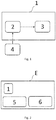
- Fig. 1 shows a schematic block diagram of a device 1 for predicting a possible collision of an ego vehicle E with another traffic participant, designated as target T.
- the traffic participant can be, in the context of the invention, a moving object (described as a rectangle), such as a motor vehicle, a motorcycle/bicycle or alike.
- FIG. 2 A schematic view of an ego vehicle E equipped with such a device 1 and with systems of sensing 4, steering 5 and braking 6 is illustrated in Fig. 2 .
- the device 1 comprises an interface 2 which is adapted to receive input data from any active form of remote sensing, such as radar, lidar, optic or infrared sensors, for example.
- the received input data are related to a target external to said ego vehicle E, said target T being present in a predetermined scanning zone of the sensing system 4.
- the traffic participant designated as target T in this description is an oncoming vehicle, whose direction (angle) of movement over ground has been detected and history of measurement positions has been generated as a trace.
- the device 1 comprises an evaluation unit 3 adapted to construct an approximated path (trajectory) of target T based on the measured trace, for example, using regression.
- the core can be considered the curve parallel to the computed trajectory that contains the intersection of the diagonals (for rectangle objects, as in the illustrated case), and the edges of the path are the parallels that contain the corners considered in the direction of movement of target T.
- the evaluation unit 3 is further adapted to compute the probability for the ego vehicle E to reach the most critical intersection points within a predefined time interval, according to the method which is described in detail in the following section.
- ego vehicle E follows a circular path, i.e. having a constant curve, with a constant speed.
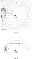
- the curve driven by a modern car can be obtained via the vehicle's CAN. It is computed based on information obtained from steering angle sensors. For the position of the steering wheel considered, the car is supposed to drive on a circle. That's why the curve information is computed as 1/R, where R is the radius of the circle on which the center of gravity CoG of the car is considered to run in that specific moment. Every other point of the car will describe a circle that is concentric with this one and so are the wheels of the car, which are tangent, in their middle, to such circles. The center of these circles, called the center of rotation CoR of the vehicle, is on the line that contains the rear axle of the car, as shown in Fig. 3 .
- the value of the radical alone is the radius of the circle that contains the center of the rear axle, R Ra .
- the CoG circle is what is called the core of the path (there are given later more details about it), on which the distance to be run by the vehicle can be computed, and on which the overall speed is also computed. It is considered to be an appropriate choice, because of the fact that it has the radius close to the average of the radiuses of the circles described by all the four wheels, as it is approximately in the middle of the car.
- the path prediction for an at most 180 degrees turn of the car is taken into consideration, as shown in Fig. 4a or 4b , as turns of a greater angle are not plausible in practice. For high curve values this is the path to consider, while for lower curves the path will be limited to a certain maximum length.
- the maximum length, L max is chosen based on important properties of the function, as the maximum speed limit and the considered time to crossing values, and it is considered as length of the CoG arc of circle, starting from the ego vehicle side (i.e. front or rear).
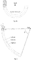
- the other arcs are limited to the intersection with the line containing the CoR and the end of the CoG arc, as seen in Fig. 5 .
- L ⁇ ⁇ ⁇ ⁇ R CoG
- ⁇ arcsin d Ra R CoG
- d Ra is the distance between the rear axle and the considered side, which distance can be easily determined from car's length and the position of the rear axle.
- the next step it is to find out the interval in which the Y coordinates of the points from the three circles are included.
- y end_left and y end_right are computed similarly.
- the next step, which computes the distance to crossing, is dependent on these intervals, as well as on the previously computed center of rotation and corresponding radiuses.
- the device 3 is afterwards able to compute the intersection points between all the path edges by equalizing the equations. This can be generalized for any possible curve type.
- x ⁇ R 2 ⁇ y ⁇ y CoR 2 ⁇ x CoR ) the minus sign being associated with driving backwards, where R is the radius of the corresponding circle and y ⁇ I y,x , where I y,x is the corresponding previously computed interval delimiting the arc.
- intersection points From here at most eight intersection points are obtained. In Fig. 6 , for example, six such intersection points can be found.
- the device 3 is able to compute the critical distance to crossing, which is the distance that the ego vehicle E has to run in order to reach the most critical intersection point. Doing this, the intersection points are predicted on the core path, as in Fig. 7 .
- the evaluation unit 3 chooses the smallest one, which is the distance D of concern, until the intersection with target T following the given curved ego's E path.
- the distance will be the length of the arc from the back of ego E to the point A'.
- the computed distance can be used to find the time to crossing (or TTC) for each of the two implied vehicles, and, based on them, it is possible to autonomously take a better decision.
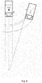
- Fig. 8 when ego vehicle has a straight path and target is predicted to have a curvilinear path bent towards ego vehicle E, the time to crossing TTC is computed more accurately. It is easy to observe, in Fig. 8 , how having computed a curved target path reduces significantly the distance to crossing for both ego E and target T, than in the case when both would have followed a straight path, situation illustrated by dashed lines. This reduces both ego's and target's time to collision (computed as distance/speed), as the speed remains the same. As TTC is one of important factors to be considered in order to take a decision, this leads to an important brake request that otherwise would have been omitted or delayed.
- FIG. 9 Another exemplary embodiment is found in Fig. 9 , where, as it can be seen, cars whose directions of movement at a certain point could be considered as intersecting for straight paths, illustrated as dashed lines, are predicted actually not to have intersecting paths. As a consequence, a false action is prevented.
- FIG. 10 another exemplary embodiment can be seen, illustrating another advantage given by this invention.
- a situation which without curved path intersections wouldn't have been a lateral collision avoidance scenario can easily be detected as such or it can, at least, be detected earlier.
- one method to detect lateral collision situations is to do an approaching angle check.
- target T might have not been detected as a critical object to take an action for, since by considering their straight paths, illustrated by interrupted lines, do not cross.
- the path intersection makes it useless to use such an approach like the one of verifying an approaching angle, because it is enough to compute the intersection of paths and to see if there's a risk of collision.
Landscapes
- Engineering & Computer Science (AREA)
- Automation & Control Theory (AREA)
- Transportation (AREA)
- Mechanical Engineering (AREA)
- Traffic Control Systems (AREA)
Abstract
The invention relates to a method and a device of predicting a possible collision between an ego vehicle and an oncoming traffic participant, at least one of them following a curved path. The method comprises the following steps: after an oncoming traffic participant is detected in a predetermined scanning zone of the ego vehicle (E) and is selected as a target (T), a measured trace of the target position, speed and angle relative to the ego vehicle is generated. Then, an approximated current core path of the target is constructed, and a current core path for the ego vehicle is computed and predicted for a maximum admissible length. The intersecting points of the predicted core path of the ego vehicle and the approximated core path of the target are computed and the most critical intersection points are taken into consideration, in order to predict a possible collision of the ego vehicle with the target based on the probability for the ego vehicle to reach the most critical intersection points within a predefined time interval.
Description
- The invention refers to a method and device of predicting a possible collision of a vehicle with an oncoming moving object, intended mainly for mitigate lateral collision.
- For autonomous or semi-autonomous driving systems, radar sensors are used in order to increase the safety of the cars, either by alerting the driver of an important danger or by triggering autonomous reactions, which can involve braking or steering the car, in case of imminent collisions.
- Short-range radars, endowed with large field of views, are mounted on a car's corners monitor large areas around the car and can be used in order to predict probable lateral collisions with other cars. Functions that alert the user about such probable collisions are already in use in passenger cars, but often they consider straight, linear trajectories to predict an intersection point, which may be sufficient for driver alert functions, for low driving speeds, or when the host vehicle is standing, but which can cause issues for more important decisions, like having to automatically brake or to steer the car in order to increase the safety of passengers.
- Patent
US8060306B2 discloses a method and system for avoiding an obstacle. The system comprises a mapping module or path filtering module which is arranged to identify admissible curved paths for which the vehicle is able to stop prior to reaching a detected obstacle in accordance with an observed translational velocity and an observed rotational velocity. A data processor determines a respective objective function for the candidate translational velocities and candidate rotational velocities associated with the admissible curved paths, where the objective function includes a curvature comparison term associated with the last curved path of the vehicle. A search engine or data processor selects preferential velocities, among the candidate translational velocities and candidate rotational velocities, with a superior value for its corresponding objective function, and the path planning module or data processor determines the vehicular speed and trajectory for a path plan that avoids the obstacle consistent with the selected preferential velocities. In this case, the invention takes into consideration the subject vehicle's path as a series of admissible curved paths, but it concerns only the case of a possible collision with a static obstacle, not a moving one. - Another patent document,
US 5841366 , discloses a traveling-path deduction apparatus and method. The said method is able to detect objects existing ahead of the vehicle and to deduce a temporary traveling path of the vehicle and to set the traveling path having the minimum time change amount in the distances. It is said that in case of a properly-set temporary traveling path, the path and running loci of the preceding vehicles are on a concentric circle. However, having to compute a plurality of temporary traveling paths with different curvatures requires a lot of computing resources, when the preceding vehicle (or the vehicle ahead) does not follow a straight trajectory. - None of the afore-mentioned inventions has addressed the lateral collision function, where having to brake the car automatically or even to steer in order to avoid a collision requires a better understanding of the movement of both the ego vehicle and an oncoming vehicle, referred as target. Models for predicting both ego and target vehicles' paths when they don't follow straight trajectories should be defined and a method of avoiding collision based on computing the distance left to the intersection point, in these cases, should be proposed.
- Therefore, there is a need for increased accuracy on predicting a possible collision of vehicles when at least one traffic participant is following a curvilinear path.
- The object of the invention is to indicate means for accurately avoiding collision between an ego vehicle and a target vehicle, when at least one of them follows a curved path.
- According to the invention, this object is achieved by the subject matters of the independent claims, namely a method and a device of predicting a possible collision, as well as a vehicle equipped with such means. Further advantageous developments are the subject matter of the dependent claims.
- According to a first aspect, the invention provides a method of predicting a possible collision of an ego vehicle with a target vehicle, at least one of them following a curve path. A traffic participant entering in a predetermined scanning area is selected and traced as a target. Its approximated current core path is constructed, and a core path of the ego vehicle is computed as well. The ego vehicle core path is predicted by extrapolation up to a maximum admissible value, and the intersecting points of the respective core paths are computed. By taking into consideration the most critical intersection points, a possible collision of the ego vehicle with the target is predicted based on the probability for the ego vehicle to reach the most critical intersection points within a predefined time interval.
- According to a second aspect, the invention provides a device of predicting a possible collision, which comprises an interface and an evaluation unit. The interface is adapted to receive sensor data related to the target, as well as ego vehicle data such as length, width, position of the rear axle and steering angle. The evaluation unit is adapted to construct the approximated core path of the target based on the received sensor data, then to compute the core path of the ego vehicle, to predict the ego vehicle core path up to a maximum admissible value and to compute the intersection points of respective core paths. By taking into consideration the most critical intersection points, the evaluation unit also is adapted to compute the probability for the ego vehicle to reach those points under a predefined time interval.
- According to a third aspect, the invention provides a vehicle equipped with a sensor system adapted to provide sensor data of a surrounding of the ego vehicle, and steering and/or braking systems able to receive signals from a device for predicting a possible collision.
- According to the invention, the most critical distance to the intersection between a steering ego vehicle and a target vehicle having crossing paths is accurately computed. Having this distance computed, a more precise time to crossing is computed for each of the two implied vehicles, and further on it is possible to autonomously take a better decision, for example when to automatically apply a brake.
- The method also enriches the set of possible scenarios of avoidance of lateral collisions and it increases as well the false positive performance. Also, the considered function can be executed, this way, in other situations as well, like the case when target vehicle is steering.
- According to a preferred embodiment of the method, it is computed the critical distance required to be travelled by the ego vehicle to intersect the target.
- According to another embodiment of the method, it is computed the time to crossing the computed critical distance by the ego vehicle.
- According to another embodiment of the method, it is defined a threshold that identify a time to collision with the target by the ego vehicle, and providing signals to the ego vehicle to effect the ego vehicle steering or braking systems, when the computed time to crossing exceeds the defined time to collision.
- According to particular embodiment of the method, the curvilinear core path is delimited by the curves given by the radiuses of the circles described by all four corners of the ego vehicle.
- According to a particular embodiment of the method, the maximum length of the core path for the ego vehicle corresponds to a steer angle of 180°.
- According to a particular embodiment of the method, the current approximated core path of the target is constructed using regression.
- According to a particular embodiment of the method, the curvilinear path of the ego vehicle is computed as a circular path when the steering angle of the ego vehicle is constant.
- According to a particular embodiment of the method, the curvilinear path of the ego vehicle is computed as a combination of curvilinear and rectilinear parts.
- According to a particular embodiment of the method, the curvilinear path is computed as a part of complex curve, like parabola, clothoid, or the like, when the steering angle of the ego vehicle is not constant.
- According to a preferred embodiment of the device, the evaluation unit is adapted to construct the current approximated core path of the target using regression.
- According to another embodiment of the device, the evaluation unit is adapted to compute the critical distance required to be travelled by the ego vehicle to intersect the target.
- According to another embodiment of the device, the evaluation unit is adapted to compute the critical distance required to be travelled by the ego vehicle to intersect the target.
- According to another embodiment of the device, the evaluation unit is adapted to compute a time to crossing the computed critical distance for ego vehicle.
- According to another embodiment of the device, the evaluation unit is further adapted to define a threshold that identify a time to collision with the target by the ego vehicle, and providing signals to the ego vehicle to effect the ego vehicle steering or braking systems, when the computed time to crossing exceeds the defined time to collision.
- For a more complete understanding of the invention and the advantages thereof, exemplary embodiments of the invention are explained in more detail in the following description with reference to the attached figures, in which similar reference numbers designate similar parts. The figures show:
-
Fig. 1 - a schematic block diagram of a device for predicting a possible collision of a vehicle with a target, according to an embodiment of the invention; -
Fig. 2 - a schematic block diagram of a vehicle equipped with steering and braking systems and with a device according to an embodiment of the invention; -
Fig. 3 - a schematic top view of a steering ego vehicle according to the invention; -
Fig. 4a - a top view of a possible curved core path for forward movement; -
Fig. 4b - a top view of a possible curved core path for backward movement; -
Fig. 5 - an illustration of a reverse path; -
Fig. 6 - an example of intersection of ego vehicle and target core paths where the ego core path is circular and bends towards the target core path, which is straight; -
Fig. 7 - an example of prediction of the intersection points on the core path, computed according to the invention; -
Fig. 8 - an example of a possible road scenario, where a curved target core path bends towards an ego straight core path; -
Fig. 9 - a possible road scenario where ego and target curved core paths do not cross; -
Fig. 10 - a possible road scenario of lateral collision between a steering ego vehicle and a target vehicle having a straight path; -
Fig. 11 - a flowchart of a method for predicting a possible collision of the ego vehicle with a target, according to the invention. -
Fig. 1 shows a schematic block diagram of adevice 1 for predicting a possible collision of an ego vehicle E with another traffic participant, designated as target T. The traffic participant can be, in the context of the invention, a moving object (described as a rectangle), such as a motor vehicle, a motorcycle/bicycle or alike. - A schematic view of an ego vehicle E equipped with such a
device 1 and with systems ofsensing 4, steering 5 andbraking 6 is illustrated inFig. 2 . - The
device 1 comprises aninterface 2 which is adapted to receive input data from any active form of remote sensing, such as radar, lidar, optic or infrared sensors, for example. The received input data are related to a target external to said ego vehicle E, said target T being present in a predetermined scanning zone of thesensing system 4. In order to facilitate the understanding of the invention, the traffic participant designated as target T in this description is an oncoming vehicle, whose direction (angle) of movement over ground has been detected and history of measurement positions has been generated as a trace. - Further on, the
device 1 comprises anevaluation unit 3 adapted to construct an approximated path (trajectory) of target T based on the measured trace, for example, using regression. No matter the method used and the obtained trajectory, the core can be considered the curve parallel to the computed trajectory that contains the intersection of the diagonals (for rectangle objects, as in the illustrated case), and the edges of the path are the parallels that contain the corners considered in the direction of movement of target T. - The
evaluation unit 3 is further adapted to compute the probability for the ego vehicle E to reach the most critical intersection points within a predefined time interval, according to the method which is described in detail in the following section. - It is of interest, for the purpose of this invention, to discuss all the situations requiring to compute the minimum distance to be travelled by the ego vehicle E up to virtually crossing of target T, when at least one of them doesn't have a rectilinear trajectory. For the case when both ego vehicle E and target T follow rectilinear paths simpler solutions already exist.
- For the beginning, the case of an ego vehicle E following a circular path will be detailed in the following.
- In this case, ego vehicle E follows a circular path, i.e. having a constant curve, with a constant speed. At every instant, the curve driven by a modern car can be obtained via the vehicle's CAN. It is computed based on information obtained from steering angle sensors. For the position of the steering wheel considered, the car is supposed to drive on a circle. That's why the curve information is computed as 1/R, where R is the radius of the circle on which the center of gravity CoG of the car is considered to run in that specific moment. Every other point of the car will describe a circle that is concentric with this one and so are the wheels of the car, which are tangent, in their middle, to such circles. The center of these circles, called the center of rotation CoR of the vehicle, is on the line that contains the rear axle of the car, as shown in
Fig. 3 . - Both the X-axis position of the CoG (on Y-axis it has the value 0, which is in the middle of the car), xCoG, and of the rear axle, xRa , are known. By knowing the curve, the position of the CoG and the position of the rear axle, it is possible to compute the Y coordinate of the center of rotation CoR of the vehicle as follows:

- The value of the radical alone is the radius of the circle that contains the center of the rear axle, RRa. By knowing that, the width, the length of the car, and the position of the rear axle (already known), it is possible to easily determine radiuses of the circles described by all four corners of the car, which are of interest together with the trajectory of the CoG, depending on the direction of movement. They are computed as hypotenuses in right triangles where the catheti can be easily determined from the abovementioned values. As the center of the rotation circle is already known, it is possible now to describe the path of ego vehicle R, described by arcs of circle, as in
Fig. 4a orFig. 4b . - After having finished the computations suggested so far, for each direction of movement (i.e. forward or, respectively, backwards) the position of the center of rotation, (xCoR, yCoR), and the radiuses, Rleft, Rright, RCoG, are obtained. These inputs are enough in order to describe the circles that the respective points from the car would follow for a movement with constant curve and speed.
- The CoG circle is what is called the core of the path (there are given later more details about it), on which the distance to be run by the vehicle can be computed, and on which the overall speed is also computed. It is considered to be an appropriate choice, because of the fact that it has the radius close to the average of the radiuses of the circles described by all the four wheels, as it is approximately in the middle of the car.
- Other core paths can also be considered, depending on how the overall speed and the distance are computed for the respective vehicles, like the one containing the intersection of the diagonals of the axles, but the differences should be insignificant for average cars.
- The path prediction for an at most 180 degrees turn of the car is taken into consideration, as shown in
Fig. 4a or4b , as turns of a greater angle are not plausible in practice. For high curve values this is the path to consider, while for lower curves the path will be limited to a certain maximum length. The maximum length, Lmax , is chosen based on important properties of the function, as the maximum speed limit and the considered time to crossing values, and it is considered as length of the CoG arc of circle, starting from the ego vehicle side (i.e. front or rear). The other arcs are limited to the intersection with the line containing the CoR and the end of the CoG arc, as seen inFig. 5 . - The length of the path considered, for a 180 degrees turn is:

Fig. 5 ) is the unsigned value of the angle at the center of the CoG circle of the arc delimited by the rear axle and the ego vehicle E side (i.e. front or rear).
- When L > Lmax , the β angle is computed (see
Fig. 5 ), which corresponds to an Lmax path length, as

- Then the total angle γ is computed as

- After all the angles of interest at the center of the circles are determined, the next step it is to find out the interval in which the Y coordinates of the points from the three circles are included. For the edges of the path, the end of this interval, towards the car, for the left edge is


- For the CoG arc, for a right turn it is


- For the other end of the interval, the following formula is used for the computation of the interval limit, for the CoG arc:


- So far, it has been provided one example of calculation of ego's path, for the case of constant curve (ego vehicle E follows a circular trajectory), each cycle, and the speed lower than the maximum value for which the car could follow that curve. However, the same idea applies for any other method of computing the ego's path, like when considering more complex trajectories, as, for example, arcs of clothoids, parabolas, combinations of any curves with rectilinear trajectories etc., and also to any method of computing a curved target's path (so that the distance of target T to the intersection point can be computed).
- On the exemplary embodiment discussed so far, it is shown how to compute the intersection of the paths and, later, the distance that ego vehicle E has until the intersection with the path of target T. In order to keep the example simple, a rectilinear movement is considered for target T. In
Fig. 6 such a possible road scenario is illustrated. - Here, a target, T, whose path edges have been already computed is shown.
- In this situation, knowing the position of the upper left corner (front-right, considering the direction of movement), (xcr ,ycr ), the equation of the line describing the corresponding path's edge is:

- Having the equation of the two arcs of circle describing ego's path edges, the
device 3 is afterwards able to compute the intersection points between all the path edges by equalizing the equations. This can be generalized for any possible curve type. - In the illustrated case:

- From these equations four quadratic equations are obtained, having the form:

- From here at most eight intersection points are obtained. In
Fig. 6 , for example, six such intersection points can be found. - Having computed the intersection points as above, the
device 3 is able to compute the critical distance to crossing, which is the distance that the ego vehicle E has to run in order to reach the most critical intersection point. Doing this, the intersection points are predicted on the core path, as inFig. 7 . - To do this, for the illustrated case, the angles αx at the center of the circle are computed for all the intersection points, like in the αA example from
Fig. 7 , for point A, with the mathematical expression:

Fig. 5 , already computed. With all these distances, theevaluation unit 3 chooses the smallest one, which is the distance D of concern, until the intersection with target T following the given curved ego's E path. For the illustrated case, the distance will be the length of the arc from the back of ego E to the point A'. - The same method will be applied to all the possible ego vehicle E or target T path curves (as seen in
Fig. 7 ), given appropriate methods of computing the prediction on the core path of the intersection points and of computing the distance, on the core (which would be the length of a considered arc of the core, or a sum of such values, for combined trajectories), towards this prediction. - The computed distance can be used to find the time to crossing (or TTC) for each of the two implied vehicles, and, based on them, it is possible to autonomously take a better decision.
- According to another embodiment illustrated in
Fig. 8 , when ego vehicle has a straight path and target is predicted to have a curvilinear path bent towards ego vehicle E, the time to crossing TTC is computed more accurately. It is easy to observe, inFig. 8 , how having computed a curved target path reduces significantly the distance to crossing for both ego E and target T, than in the case when both would have followed a straight path, situation illustrated by dashed lines. This reduces both ego's and target's time to collision (computed as distance/speed), as the speed remains the same. As TTC is one of important factors to be considered in order to take a decision, this leads to an important brake request that otherwise would have been omitted or delayed. - The same conclusion can apply for the case when target T would have followed a rectilinear path and ego vehicle E a similar curved path or when both would have had curved paths.
- In a similar way an otherwise small computed time to collision can become bigger when one of the cars is steering away from the other one and this way an action can be safely delayed or even avoided, if it would have been unintended. This is desired because it reduces the risk of entering in a conflict with driver's decisions, with too early actions.
- Another exemplary embodiment is found in
Fig. 9 , where, as it can be seen, cars whose directions of movement at a certain point could be considered as intersecting for straight paths, illustrated as dashed lines, are predicted actually not to have intersecting paths. As a consequence, a false action is prevented. - In
Fig. 10 another exemplary embodiment can be seen, illustrating another advantage given by this invention. A situation which without curved path intersections wouldn't have been a lateral collision avoidance scenario can easily be detected as such or it can, at least, be detected earlier. When considering straight paths, one method to detect lateral collision situations is to do an approaching angle check. - In the situation illustrated in
Fig. 10 , target T might have not been detected as a critical object to take an action for, since by considering their straight paths, illustrated by interrupted lines, do not cross. In this situation, the path intersection makes it useless to use such an approach like the one of verifying an approaching angle, because it is enough to compute the intersection of paths and to see if there's a risk of collision. - The same observation could apply to variations of this scenario, like the situation when target T is steering towards the ego E, or both of them steer toward the other.
- While certain embodiments of the present invention have been described in detail, those familiar with the art to which this invention relates will recognize various alternative designs and embodiments for practicing the invention as defined by the following claims.
-
- 1
- device
- 2
- interface
- 3
- evaluation unit
- 4
- sensor system
- 5
- steering system
- 6
- braking system
- E
- ego vehicle
- T
- target
- CoG
- center of gravity
- CoR
- center of rotation
Claims (16)
- A method of predicting a possible collision between an ego vehicle and an oncoming traffic participant, at least one of them following a curved path, the method comprising:- (S1) when said oncoming traffic participant is detected in a predetermined scanning zone, selecting the traffic participant as a target;- (S2) generating a measured trace of the target position, speed and angle;- (S3) constructing an approximated current core path of the target,- (S4) computing a core path of the ego vehicle, assuming the ego vehicle width, length, position of the rear axle and steering angle,- (S5) predicting the ego vehicle core path by extrapolating the current core path for a maximum admissible length;- (S6) computing the intersecting points of the predicted core path of the ego vehicle and the approximated core path of the target and taking into consideration the most critical intersection point;- (S7) predicting a possible collision of the ego vehicle with the target based on the probability for the ego vehicle to reach the most critical intersection points within a predefined time interval.
- Method according to claim 1, characterized by that it also comprises (S71) computing the critical distance required to be travelled by the ego vehicle to intersect the target.
- Method according to claim 1, characterized by that it also comprises (S72) computing time to crossing the computed critical distance for ego vehicle.
- Method according to claim 1, characterized in that comprises defining a threshold that identify a time to collision with the target by the ego vehicle, and providing signals to the ego vehicle to effect the ego vehicle steering or braking systems, when the computed time-to-crossing exceeds the defined time to collision.
- Method according to claims 1, characterized in that the curvilinear core path is delimited by the curves given by the radiuses of the circles described by all four corners of the ego vehicle.
- Method according to claims 1 and 2, characterized in that the maximum length of the core path for the ego vehicle corresponds to a steer angle of 180°.
- Method according to any of the precedent claims, characterized by that current approximated core path of the target is constructed using regression.
- Method according to claim 1, characterized in that the curvilinear path of the ego vehicle is computed as a circular path when the steering angle of the ego vehicle is constant.
- Method according to claim 1, characterized in that the curvilinear path of the ego vehicle is computed as a combination of curvilinear and rectilinear parts.
- Method according to claim 1, characterized in that the curvilinear path is computed as a part of complex curve, like parabola, clothoid, or the like, when the steering angle of the ego vehicle is not constant.
- A device (1) of predicting a possible collision, comprising:- an interface (2) adapted to receive sensor data related to a target, as well as ego vehicle data such as length, width, position of the rear axle and steering angle;- an evaluation unit (3) adapted too construct a current approximated core path of the target based on the received sensor data;o compute a core path of the ego vehicle,o predict the ego vehicle core path by extrapolating the current core path for a maximum admissible value;o compute the intersecting points of the predicted core path of the ego vehicle and the core path of the target and to take into consideration the most critical intersection points;o compute the probability for the ego vehicle to reach the most critical intersection points within a predefined time interval.
- Device according to claim 11, characterized in that the evaluation unit (3) is adapted to construct the current approximated core path of the target using regression.
- Device according to claim 11, characterized in that the evaluation unit (3) is adapted to compute the critical distance required to be travelled by the ego vehicle to intersect the target.
- Device according to claims 11-13, characterized in that the evaluation unit (3) is adapted to compute a time to crossing the computed critical distance for ego vehicle.
- Device according to claims 11-14, characterized in that the evaluation unit (3) is further adapted to define a threshold that identify a time to collision with the target by the ego vehicle, and providing signals to the ego vehicle to effect the ego vehicle steering (5) or braking (6) systems, when the computed time to crossing exceeds the defined time to collision.
- A vehicle equipped with a sensor system (4) adapted to provide sensor data of a surrounding of the ego vehicle, and steering (5) and/or braking (6)systems able to receive signals from a device according to any of the claims 11 to 15.
Priority Applications (1)
| Application Number | Priority Date | Filing Date | Title |
|---|---|---|---|
| EP17465548.0A EP3456596A1 (en) | 2017-09-14 | 2017-09-14 | Method and device of predicting a possible collision |
Applications Claiming Priority (1)
| Application Number | Priority Date | Filing Date | Title |
|---|---|---|---|
| EP17465548.0A EP3456596A1 (en) | 2017-09-14 | 2017-09-14 | Method and device of predicting a possible collision |
Publications (1)
| Publication Number | Publication Date |
|---|---|
| EP3456596A1 true EP3456596A1 (en) | 2019-03-20 |
Family
ID=60001846
Family Applications (1)
| Application Number | Title | Priority Date | Filing Date |
|---|---|---|---|
| EP17465548.0A Withdrawn EP3456596A1 (en) | 2017-09-14 | 2017-09-14 | Method and device of predicting a possible collision |
Country Status (1)
| Country | Link |
|---|---|
| EP (1) | EP3456596A1 (en) |
Cited By (12)
| Publication number | Priority date | Publication date | Assignee | Title |
|---|---|---|---|---|
| CN110562222A (en) * | 2019-08-30 | 2019-12-13 | 驭势(上海)汽车科技有限公司 | Emergency braking control method for curve scene, vehicle-mounted device and storage medium |
| CN111309013A (en) * | 2020-02-24 | 2020-06-19 | 广州小鹏汽车科技有限公司 | Collision distance determination method and system, vehicle and storage medium |
| CN112026762A (en) * | 2020-09-15 | 2020-12-04 | 北京经纬恒润科技有限公司 | Vehicle collision analysis method and device |
| CN113071482A (en) * | 2021-04-28 | 2021-07-06 | 江苏大学 | Intelligent vehicle anti-collision method based on passing time interval |
| CN113705636A (en) * | 2021-08-12 | 2021-11-26 | 重庆邮电大学 | Method and device for predicting trajectory of automatic driving vehicle and electronic equipment |
| CN111409631B (en) * | 2020-04-10 | 2022-01-11 | 新石器慧通(北京)科技有限公司 | Vehicle running control method and device, vehicle and storage medium |
| CN114882706A (en) * | 2022-05-31 | 2022-08-09 | 华中科技大学 | Circumferential anti-collision early warning method and system based on non-structural pavement |
| FR3121255A1 (en) * | 2021-03-26 | 2022-09-30 | Psa Automobiles Sa | Method and device for signaling a reversing maneuver of an autonomous vehicle. |
| EP4223604A1 (en) * | 2022-02-04 | 2023-08-09 | Renault s.a.s | Method for detecting danger in the environment of a motor vehicle |
| DE102022123474A1 (en) * | 2022-09-14 | 2024-03-14 | Valeo Schalter Und Sensoren Gmbh | Method for calculating a predicted time until a possible collision between two motor vehicles, computer program and driver assistance system |
| WO2025152862A1 (en) * | 2024-01-19 | 2025-07-24 | 北京京东远升科技有限公司 | Method and apparatus for controlling travelling speed of autonomous vehicle |
| EP4603352A3 (en) * | 2024-06-28 | 2025-12-24 | Shanghai Horizon Intelligent Automotive Technology Co., Ltd. | Method and apparatus for determining time to collision, device, and storage medium |
Citations (7)
| Publication number | Priority date | Publication date | Assignee | Title |
|---|---|---|---|---|
| US5841366A (en) | 1995-07-20 | 1998-11-24 | Mazda Motor Coporaton | Traveling-path deduction apparatus and method for vehicles |
| JP2007164339A (en) * | 2005-12-12 | 2007-06-28 | Toyota Central Res & Dev Lab Inc | Calculation processing program, calculation processing apparatus, and calculation processing method |
| EP2208654A1 (en) * | 2009-01-15 | 2010-07-21 | Ford Global Technologies, LLC | Method and system for avoiding host vehicle collisions with a target |
| US8060306B2 (en) | 2007-10-04 | 2011-11-15 | Deere & Company | Method and system for obstacle avoidance for a vehicle |
| EP2495713A1 (en) * | 2009-10-30 | 2012-09-05 | Toyota Jidosha Kabushiki Kaisha | Driving support device |
| US20140303882A1 (en) * | 2013-04-05 | 2014-10-09 | Electronics And Telecommunications Research Institute | Apparatus and method for providing intersection collision-related information |
| EP3006294A1 (en) * | 2013-05-31 | 2016-04-13 | Hitachi Automotive Systems, Ltd. | Vehicle control device |
-
2017
- 2017-09-14 EP EP17465548.0A patent/EP3456596A1/en not_active Withdrawn
Patent Citations (7)
| Publication number | Priority date | Publication date | Assignee | Title |
|---|---|---|---|---|
| US5841366A (en) | 1995-07-20 | 1998-11-24 | Mazda Motor Coporaton | Traveling-path deduction apparatus and method for vehicles |
| JP2007164339A (en) * | 2005-12-12 | 2007-06-28 | Toyota Central Res & Dev Lab Inc | Calculation processing program, calculation processing apparatus, and calculation processing method |
| US8060306B2 (en) | 2007-10-04 | 2011-11-15 | Deere & Company | Method and system for obstacle avoidance for a vehicle |
| EP2208654A1 (en) * | 2009-01-15 | 2010-07-21 | Ford Global Technologies, LLC | Method and system for avoiding host vehicle collisions with a target |
| EP2495713A1 (en) * | 2009-10-30 | 2012-09-05 | Toyota Jidosha Kabushiki Kaisha | Driving support device |
| US20140303882A1 (en) * | 2013-04-05 | 2014-10-09 | Electronics And Telecommunications Research Institute | Apparatus and method for providing intersection collision-related information |
| EP3006294A1 (en) * | 2013-05-31 | 2016-04-13 | Hitachi Automotive Systems, Ltd. | Vehicle control device |
Cited By (16)
| Publication number | Priority date | Publication date | Assignee | Title |
|---|---|---|---|---|
| CN110562222A (en) * | 2019-08-30 | 2019-12-13 | 驭势(上海)汽车科技有限公司 | Emergency braking control method for curve scene, vehicle-mounted device and storage medium |
| CN111309013A (en) * | 2020-02-24 | 2020-06-19 | 广州小鹏汽车科技有限公司 | Collision distance determination method and system, vehicle and storage medium |
| CN111309013B (en) * | 2020-02-24 | 2022-12-13 | 广州小鹏汽车科技有限公司 | A collision distance determination method and system, vehicle, and storage medium |
| CN111409631B (en) * | 2020-04-10 | 2022-01-11 | 新石器慧通(北京)科技有限公司 | Vehicle running control method and device, vehicle and storage medium |
| CN112026762A (en) * | 2020-09-15 | 2020-12-04 | 北京经纬恒润科技有限公司 | Vehicle collision analysis method and device |
| CN112026762B (en) * | 2020-09-15 | 2021-06-29 | 北京经纬恒润科技股份有限公司 | Method and device for analyzing vehicle collision |
| FR3121255A1 (en) * | 2021-03-26 | 2022-09-30 | Psa Automobiles Sa | Method and device for signaling a reversing maneuver of an autonomous vehicle. |
| CN113071482A (en) * | 2021-04-28 | 2021-07-06 | 江苏大学 | Intelligent vehicle anti-collision method based on passing time interval |
| CN113705636A (en) * | 2021-08-12 | 2021-11-26 | 重庆邮电大学 | Method and device for predicting trajectory of automatic driving vehicle and electronic equipment |
| CN113705636B (en) * | 2021-08-12 | 2024-02-20 | 重庆邮电大学 | An automatic driving vehicle trajectory prediction method, device and electronic equipment |
| EP4223604A1 (en) * | 2022-02-04 | 2023-08-09 | Renault s.a.s | Method for detecting danger in the environment of a motor vehicle |
| FR3132482A1 (en) * | 2022-02-04 | 2023-08-11 | Renault S.A.S | Method for detecting danger in the environment of a motor vehicle |
| CN114882706A (en) * | 2022-05-31 | 2022-08-09 | 华中科技大学 | Circumferential anti-collision early warning method and system based on non-structural pavement |
| DE102022123474A1 (en) * | 2022-09-14 | 2024-03-14 | Valeo Schalter Und Sensoren Gmbh | Method for calculating a predicted time until a possible collision between two motor vehicles, computer program and driver assistance system |
| WO2025152862A1 (en) * | 2024-01-19 | 2025-07-24 | 北京京东远升科技有限公司 | Method and apparatus for controlling travelling speed of autonomous vehicle |
| EP4603352A3 (en) * | 2024-06-28 | 2025-12-24 | Shanghai Horizon Intelligent Automotive Technology Co., Ltd. | Method and apparatus for determining time to collision, device, and storage medium |
Similar Documents
| Publication | Publication Date | Title |
|---|---|---|
| EP3456596A1 (en) | Method and device of predicting a possible collision | |
| EP3715204A1 (en) | Vehicle control device | |
| EP3611069B1 (en) | Vehicle control device | |
| US9159023B2 (en) | System for predicting a driver's intention to change lanes | |
| US20200238980A1 (en) | Vehicle control device | |
| US7729857B2 (en) | System for and method of detecting a collision and predicting a vehicle path | |
| CN101497330B (en) | A system for collision course prediction | |
| EP2990290B1 (en) | Method and system for post-collision manoeuvre planning and vehicle equipped with such system | |
| US20200353918A1 (en) | Vehicle control device | |
| CN102076541B (en) | Path generation algorithm for automated lane centering and lane changing control system | |
| US8244408B2 (en) | Method to assess risk associated with operating an autonomic vehicle control system | |
| CN104554272B (en) | The path planning of avoidance steering operation when target vehicle and surrounding objects be present | |
| EP3581449A1 (en) | Driving assist control device | |
| EP3699051A1 (en) | Vehicle control device | |
| US11390288B2 (en) | Other-vehicle action prediction method and other-vehicle action prediction device | |
| EP3048023B1 (en) | Method for assisting a driver in driving an ego vehicle and corresponding driver assistance system | |
| EP3699049A1 (en) | Vehicle control device | |
| US10752223B2 (en) | Autonomous emergency braking system and method for vehicle at crossroad | |
| EP2208654B1 (en) | Method and system for avoiding host vehicle collisions with a target | |
| CN104648395A (en) | Steering Risk Decision System And Method For Driving Narrow Roads | |
| US20200180614A1 (en) | Vehicle control device | |
| Sivaraman et al. | Merge recommendations for driver assistance: A cross-modal, cost-sensitive approach | |
| EP3597511A1 (en) | Method and system for providing a steering guidance to a driver of a host vehicle | |
| US12164036B2 (en) | Object recognition via indirect signal reflection | |
| US12391247B2 (en) | Method for controlling a motor vehicle equipped with autonomous driving means |
Legal Events
| Date | Code | Title | Description |
|---|---|---|---|
| PUAI | Public reference made under article 153(3) epc to a published international application that has entered the european phase |
Free format text: ORIGINAL CODE: 0009012 |
|
| AK | Designated contracting states |
Kind code of ref document: A1 Designated state(s): AL AT BE BG CH CY CZ DE DK EE ES FI FR GB GR HR HU IE IS IT LI LT LU LV MC MK MT NL NO PL PT RO RS SE SI SK SM TR |
|
| AX | Request for extension of the european patent |
Extension state: BA ME |
|
| STAA | Information on the status of an ep patent application or granted ep patent |
Free format text: STATUS: THE APPLICATION IS DEEMED TO BE WITHDRAWN |
|
| 18D | Application deemed to be withdrawn |
Effective date: 20190921 |