EP3456455A1 - Auto wire feeding method and wire electrical discharge machine - Google Patents
Auto wire feeding method and wire electrical discharge machine Download PDFInfo
- Publication number
- EP3456455A1 EP3456455A1 EP18193410.0A EP18193410A EP3456455A1 EP 3456455 A1 EP3456455 A1 EP 3456455A1 EP 18193410 A EP18193410 A EP 18193410A EP 3456455 A1 EP3456455 A1 EP 3456455A1
- Authority
- EP
- European Patent Office
- Prior art keywords
- wire
- wire electrode
- lower nozzle
- auto
- wire feeding
- Prior art date
- Legal status (The legal status is an assumption and is not a legal conclusion. Google has not performed a legal analysis and makes no representation as to the accuracy of the status listed.)
- Withdrawn
Links
- 238000000034 method Methods 0.000 title claims description 37
- 239000012530 fluid Substances 0.000 claims abstract description 59
- 230000007246 mechanism Effects 0.000 claims abstract description 37
- 238000003754 machining Methods 0.000 claims abstract description 9
- 238000005452 bending Methods 0.000 description 18
- 238000001514 detection method Methods 0.000 description 17
- 230000008569 process Effects 0.000 description 14
- 238000009760 electrical discharge machining Methods 0.000 description 10
- 238000010586 diagram Methods 0.000 description 6
- 239000000463 material Substances 0.000 description 4
- 230000004048 modification Effects 0.000 description 4
- 238000012986 modification Methods 0.000 description 4
- 230000007423 decrease Effects 0.000 description 3
- 238000004904 shortening Methods 0.000 description 3
- XEEYBQQBJWHFJM-UHFFFAOYSA-N Iron Chemical compound [Fe] XEEYBQQBJWHFJM-UHFFFAOYSA-N 0.000 description 2
- 239000007769 metal material Substances 0.000 description 2
- 229910001369 Brass Inorganic materials 0.000 description 1
- 229910000881 Cu alloy Inorganic materials 0.000 description 1
- 230000009471 action Effects 0.000 description 1
- 239000010951 brass Substances 0.000 description 1
- 230000008859 change Effects 0.000 description 1
- 239000008367 deionised water Substances 0.000 description 1
- 229910021641 deionized water Inorganic materials 0.000 description 1
- 230000000694 effects Effects 0.000 description 1
- 238000005516 engineering process Methods 0.000 description 1
- 230000006872 improvement Effects 0.000 description 1
- 238000003780 insertion Methods 0.000 description 1
- 230000037431 insertion Effects 0.000 description 1
- 229910052742 iron Inorganic materials 0.000 description 1
- WFKWXMTUELFFGS-UHFFFAOYSA-N tungsten Chemical compound [W] WFKWXMTUELFFGS-UHFFFAOYSA-N 0.000 description 1
- 229910052721 tungsten Inorganic materials 0.000 description 1
- 239000010937 tungsten Substances 0.000 description 1
- UONOETXJSWQNOL-UHFFFAOYSA-N tungsten carbide Chemical compound [W+]#[C-] UONOETXJSWQNOL-UHFFFAOYSA-N 0.000 description 1
- 238000011144 upstream manufacturing Methods 0.000 description 1
- XLYOFNOQVPJJNP-UHFFFAOYSA-N water Chemical compound O XLYOFNOQVPJJNP-UHFFFAOYSA-N 0.000 description 1
Images




Classifications
-
- B—PERFORMING OPERATIONS; TRANSPORTING
- B23—MACHINE TOOLS; METAL-WORKING NOT OTHERWISE PROVIDED FOR
- B23H—WORKING OF METAL BY THE ACTION OF A HIGH CONCENTRATION OF ELECTRIC CURRENT ON A WORKPIECE USING AN ELECTRODE WHICH TAKES THE PLACE OF A TOOL; SUCH WORKING COMBINED WITH OTHER FORMS OF WORKING OF METAL
- B23H1/00—Electrical discharge machining, i.e. removing metal with a series of rapidly recurring electrical discharges between an electrode and a workpiece in the presence of a fluid dielectric
- B23H1/04—Electrodes specially adapted therefor or their manufacture
-
- B—PERFORMING OPERATIONS; TRANSPORTING
- B23—MACHINE TOOLS; METAL-WORKING NOT OTHERWISE PROVIDED FOR
- B23H—WORKING OF METAL BY THE ACTION OF A HIGH CONCENTRATION OF ELECTRIC CURRENT ON A WORKPIECE USING AN ELECTRODE WHICH TAKES THE PLACE OF A TOOL; SUCH WORKING COMBINED WITH OTHER FORMS OF WORKING OF METAL
- B23H1/00—Electrical discharge machining, i.e. removing metal with a series of rapidly recurring electrical discharges between an electrode and a workpiece in the presence of a fluid dielectric
- B23H1/02—Electric circuits specially adapted therefor, e.g. power supply, control, preventing short circuits or other abnormal discharges
-
- B—PERFORMING OPERATIONS; TRANSPORTING
- B23—MACHINE TOOLS; METAL-WORKING NOT OTHERWISE PROVIDED FOR
- B23H—WORKING OF METAL BY THE ACTION OF A HIGH CONCENTRATION OF ELECTRIC CURRENT ON A WORKPIECE USING AN ELECTRODE WHICH TAKES THE PLACE OF A TOOL; SUCH WORKING COMBINED WITH OTHER FORMS OF WORKING OF METAL
- B23H11/00—Auxiliary apparatus or details, not otherwise provided for
-
- B—PERFORMING OPERATIONS; TRANSPORTING
- B23—MACHINE TOOLS; METAL-WORKING NOT OTHERWISE PROVIDED FOR
- B23H—WORKING OF METAL BY THE ACTION OF A HIGH CONCENTRATION OF ELECTRIC CURRENT ON A WORKPIECE USING AN ELECTRODE WHICH TAKES THE PLACE OF A TOOL; SUCH WORKING COMBINED WITH OTHER FORMS OF WORKING OF METAL
- B23H7/00—Processes or apparatus applicable to both electrical discharge machining and electrochemical machining
- B23H7/02—Wire-cutting
- B23H7/08—Wire electrodes
- B23H7/10—Supporting, winding or electrical connection of wire-electrode
- B23H7/101—Supply of working media
-
- B—PERFORMING OPERATIONS; TRANSPORTING
- B23—MACHINE TOOLS; METAL-WORKING NOT OTHERWISE PROVIDED FOR
- B23H—WORKING OF METAL BY THE ACTION OF A HIGH CONCENTRATION OF ELECTRIC CURRENT ON A WORKPIECE USING AN ELECTRODE WHICH TAKES THE PLACE OF A TOOL; SUCH WORKING COMBINED WITH OTHER FORMS OF WORKING OF METAL
- B23H7/00—Processes or apparatus applicable to both electrical discharge machining and electrochemical machining
- B23H7/02—Wire-cutting
- B23H7/08—Wire electrodes
- B23H7/10—Supporting, winding or electrical connection of wire-electrode
- B23H7/102—Automatic wire threading
-
- B—PERFORMING OPERATIONS; TRANSPORTING
- B23—MACHINE TOOLS; METAL-WORKING NOT OTHERWISE PROVIDED FOR
- B23H—WORKING OF METAL BY THE ACTION OF A HIGH CONCENTRATION OF ELECTRIC CURRENT ON A WORKPIECE USING AN ELECTRODE WHICH TAKES THE PLACE OF A TOOL; SUCH WORKING COMBINED WITH OTHER FORMS OF WORKING OF METAL
- B23H7/00—Processes or apparatus applicable to both electrical discharge machining and electrochemical machining
- B23H7/02—Wire-cutting
- B23H7/08—Wire electrodes
- B23H7/10—Supporting, winding or electrical connection of wire-electrode
- B23H7/105—Wire guides
Definitions
- the present invention relates to an auto wire feeding method for automatically feeding a wire electrode, as well as relating to a wire electrical discharge machine.
- Description of the Related Art Japanese Laid-Open Patent Publication No. 58-177234 discloses an auto wire feeding method in a wire electrical discharge machine, in which a wire electrode from a wire electrode supply unit is threaded into a machining start hole of a workpiece, and fed to and engaged with the wire electrode collecting unit, whereas when the wire electrode fails to be engaged with the wire electrode collecting unit, the wire electrode is automatically rewound and returned to the initial state.
- the present invention has been devised to solve the above problem, and it is therefore an object of the present invention to provide an auto wire feeding method and a wire electrical discharge machine capable of shortening the time required for completion of auto feeding of a wire electrode and improving the success rate of auto wire feeding.
- An aspect of the present invention resides in an auto wire feeding method for performing auto wire feeding of a wire electrode in a wire electrical discharge machine.
- the wire electrical discharge machine includes: a work-pan configured to store working fluid; a table disposed in the work-pan, a workpiece being placed on the table; a lower nozzle disposed under the table and having a nozzle hole into which the wire electrode is inserted; a contact detector disposed at the lower nozzle and configured to detect contact of the wire electrode with the exterior of the lower nozzle; a suction unit configured to suction working fluid into the lower nozzle; and a wire feeding mechanism configured to pass the wire electrode through a machining hole in the workpiece and feed the wire electrode toward the lower nozzle.
- the auto wire feeding method includes the steps of: when auto wire feeding is performed with the work-pan containing working fluid, feeding the wire electrode toward the lower nozzle by the wire feeding mechanism while suctioning the working fluid into the lower nozzle by the suction unit; and rewinding the wire electrode by the wire feeding mechanism when the contact detector detects contact of the wire electrode with the exterior of the lower nozzle.
- FIG. 1 is a schematic diagram of a wire electrical discharge machine 10.
- the wire electrical discharge machine 10 is a machine tool for performing electrical discharge machining on a workpiece 14 by applying voltage between a wire electrode 12 and the workpiece 14 to thereby generate electrical discharge.
- the wire electrode 12 is formed of, for example, metal material such as tungsten-based, copper-alloy based and brass-based material.
- the material of the workpiece 14 is metal material such as iron-based material or superhard material (tungsten carbide).
- the wire electrical discharge machine 10 at least, includes a main machine body 16 and a controller 18.
- the main machine body 16 is provided with a work-pan 20 capable of storing a dielectric working fluid (hereinafter simply referred to as a working fluid) such as deionized water or oil used for electrical discharge machining on the workpiece 14.
- the work-pan 20 contains therein a table 22 on which the workpiece 14 is fixed.
- the work-pan 20 is movable on a horizontal plane by an unillustrated servo motor. As the work-pan 20 is moved, the workpiece 14 fixed on the table 22 moves relative to the wire electrode 12 accordingly. By performing electrical discharge machining on the workpiece 14 while moving the workpiece relative to the wire electrode 12, it is possible to machine the workpiece 14 into a desired shape.
- the main machine body 16 has an upper wire guide 24 and a lower wire guide 26.
- the upper wire guide 24 is arranged above the workpiece 14, and the lower wire guide 26 is arranged under the workpiece 14.
- the upper wire guide 24 has an upper nozzle 28 for ejecting a working fluid through a nozzle hole thereof into which the wire electrode 12 is inserted, and an upper electrode pin 30 through which electric power is supplied to the wire electrode 12.
- the lower wire guide 26 has a lower nozzle 32 for suctioning and ejecting a working fluid through a nozzle hole thereof into which the wire electrode 12 is inserted, and a lower electrode pin 34 through which electric power is supplied to the wire electrode 12.
- the upper nozzle 28 and the lower nozzle 32 are connected to a pump 36 which is driven under control of the controller 18.
- the pump 36 supplies a working fluid into the interior of the upper nozzle 28 and the lower nozzle 32 and suctions a working fluid into the lower nozzle 32.
- the pump 36 constitutes a suction unit 38.
- the main machine body 16 has a running mechanism 44 for feeding the wire electrode 12 from a bobbin 40 through the machining hole of the workpiece 14 to a collecting box 42.
- the running mechanism 44 includes, in order from the upstream side in the running direction of the wire electrode 12, the bobbin 40, a guide roller 48, a guide roller 50, a brake roller 52, a guide roller 56, an auto wire feeding (AWF) pipe 58, the upper wire guide 24, the lower wire guide 26, a guide roller 62, a lower pipe 64, a pinch roller 66 and a feed roller 68.
- This running mechanism 44 defines a running path of the wire electrode 12.
- the running mechanism 44 constitutes a wire feeding mechanism 45.
- the bobbin 40 is rotated by a torque applied from a motor 46 which is driven under control of the controller 18.
- a long wire electrode 12 is wound on the bobbin 40, and the wire electrode 12 is supplied or fed from the bobbin 40 as the bobbin 40 rotates.
- the wire electrode 12 supplied from the bobbin 40 is extended on and along the guide roller 48 and the guide roller 50.
- the guide roller 48 and the guide roller 50 change the running direction of the wire electrode 12 fed out from the bobbin 40, and guide the wire electrode 12 toward the brake roller 52.
- the brake roller 52 is rotated by a torque applied from a motor 54 which is driven under control of the controller 18.
- the brake roller 52 can feed the wire electrode 12 without slipping, and it is possible to apply a braking force to the wire electrode 12 by adjusting the torque applied from the motor 46 to the brake roller 52.
- the wire electrode 12 sent from the brake roller 52 is extended on the guide roller 56 and then sent to the AWF pipe 58.
- a tension detector 60 is disposed between the brake roller 52 and the guide roller 56.
- the tension detector 60 is a sensor for detecting the tension of the wire electrode 12.
- the wire electrode 12 sent to the AWF pipe 58 passes therethrough and is sent to the upper wire guide 24.
- the wire electrode 12 sent to the upper wire guide 24 passes through the machining hole of the workpiece 14 and is sent to the lower wire guide 26.
- the wire electrode 12 sent to the lower wire guide 26 is extended over the guide roller 62 provided in the lower wire guide 26 and then sent to the lower pipe 64.
- the wire electrode 12 sent to the lower pipe 64 after passing through the lower pipe 64, is sent into the collecting box 42 by the pinch roller 66 and the feed roller 68 that hold and sandwich the wire electrode 12 therebetween.
- the feed roller 68 is rotated by a torque applied from a motor 70 which is driven under control of the controller 18.
- the running mechanism 44 automatically feeds the wire electrode 12 (auto wire feeding). Auto wire feeding is performed in a state in which the working fluid is stored in the work-pan 20. When the auto wire feeding fails, the wire electrode 12 is rewound, and the wire electrode 12 is then automatically fed again.
- a flexure detector 72 and a contact detector 76 are provided in the main machine body 16.
- the tip of the wire electrode 12 travels on path segments without guiding action of the guides or the rollers. Of the segments, a segment between the upper nozzle 28 and the lower nozzle 32 is the longest. Therefore, when the wire electrode 12 is fed from the upper nozzle 28 toward the lower nozzle 32, failure of auto wire feeding tends to occur due to the tip of the wire electrode 12 deviating from the nozzle hole of the lower nozzle 32.
- the flexure detector 72 is disposed between the guide roller 56 and the AWF pipe 58, and is a sensor for detecting bending of the wire electrode 12 that is caused when the tip of the wire electrode 12 deviates from the nozzle hole of the lower nozzle 32 and touches the exterior of the lower nozzle 32.
- the contact detector 76 is disposed on the lower nozzle 32, and is a sensor for detecting contact of the wire electrode 12 with the exterior of the lower nozzle 32.
- an AWF detector 78 is provided as a sensor for detecting completion of auto wire feeding.
- the AWF detector 78 is disposed between the collecting box 42 and the pinch roller 66 and feed roller 68, and is a sensor for detecting arrival of the tip of the wire electrode 12 at the position of the AWF detector 78.
- controller 18 controls the pump 36 and the running mechanism 44 to thereby perform auto wire feeding while suctioning the working fluid through the lower nozzle 32.
- the controller 18 determines that the workpiece 14 is thick. When the thickness of the workpiece 14 is less than 150 [mm], the controller 18 determines that the workpiece 14 is thin.
- the thickness of the workpiece 14 is input to the controller 18 by the operator operating an input device or the like, before the electrical discharge machining on the workpiece 14 is started.
- a thickness measuring mechanism for automatically measuring the thickness of the workpiece 14 may be provided so that the thickness of the workpiece 14 is input from the thickness measuring mechanism to the controller 18.
- the controller 18 constitutes an auto wire feeding control unit 19.
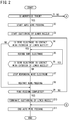
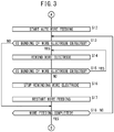
- FIGS. 2 and 3 are flowcharts showing the flow of auto wire feeding process in the controller 18.
- the controller 18 determines whether or not the thickness of the workpiece 14 is thick. If the workpiece 14 is thick, the control proceeds to step S2, and if the workpiece 14 is thin, the control goes to step S12.
- step S2 the controller 18 drives the motor 46, the motor 54 and the motor 70 to start auto wire feeding of the wire electrode 12, and the control proceeds to step S3.
- step S3 the controller 18 drives the pump 36 to suction a working fluid through the lower nozzle 32, and the control proceeds to step S4.
- step S4 the controller 18 determines whether or not the wire electrode 12 touches the exterior of the lower nozzle 32, based on the presence or absence of a detection signal from the contact detector 76.
- the controller 18 determines that the auto wire feeding has failed, by receiving the detection signal from the contact detector 76.
- the control proceeds to step S5.
- the control goes to step S9.
- step S5 the controller 18 drives the motor 46 and the motor 54 to rewind the wire electrode 12, and the control proceeds to step S6.
- step S6 the controller 18 determines whether or not the wire electrode 12 is in contact with the exterior of the lower nozzle 32, based on the presence or absence of a detection signal from the contact detector 76. If the wire electrode 12 is in contact with the exterior of the lower nozzle 32, the control returns to step S5. If the wire electrode 12 is not in contact with the exterior of the lower nozzle 32, the control goes to step S7.
- step S7 the controller 18 stops the motor 46 and the motor 54 to stop rewinding the wire electrode 12, and the control proceeds to step S8.
- step S8 the controller 18 drives the motor 46, the motor 54 and the motor 70 to restart the auto wire feeding of the wire electrode 12, and the control proceeds to step S9.
- step S9 the controller 18 determines whether or not the auto wire feeding of the wire electrode 12 is completed, based on the presence or absence of a detection signal from the AWF detector 78. When the auto wire feeding of the wire electrode 12 is completed, the control proceeds to step S10, and when the auto wire feeding of the wire electrode 12 has not yet been completed, the control returns to step S4.
- step S10 the controller 18 stops the pump 36 to complete suctioning of a working fluid through the lower nozzle 32, and the control proceeds to step S11.
- step S11 the controller 18 stops the motor 46, the motor 54 and the motor 70, terminates the auto wire feeding of the wire electrode 12, and ends the auto wire feeding process.
- electrical discharge machining may be subsequently performed without stopping the motor 46, the motor 54 and the motor 70.
- step S12 the controller 18 drives the motor 46, the motor 54 and the motor 70 to start auto wire feeding of the wire electrode 12, and the control proceeds to step S13.
- step S13 the controller 18 determines whether or not bending occurs in the wire electrode 12, based on the presence or absence of a detection signal from the flexure detector 72. The controller 18 determines that auto wire feeding has failed, by receiving the detection signal from the flexure detector 72. When bending occurs in the wire electrode 12, the control proceeds to step S14. When no bending is occurring in the wire electrode 12, the control goes to step S18.
- step S14 the controller 18 drives the motor 46 and the motor 54 to rewind the wire electrode 12, and the control proceeds to step S15.
- step S15 the controller 18 determines whether or not bending occurs in the wire electrode 12, based on the presence or absence of a detection signal from the flexure detector 72. When bending occurs in the wire electrode 12, the control returns to step S14. When no bending is occurring in the wire electrode 12, the control goes to step S16.
- step S16 the controller 18 stops the motor 46 and the motor 54 to stop rewinding of the wire electrode 12, and the control proceeds to step S17.
- step S17 the controller 18 drives the motor 46, the motor 54 and the motor 70 to restart auto wire feeding of the wire electrode 12, and the control proceeds to step S18.
- step S18 the controller 18 determines whether or not the wire feeding of the wire electrode 12 is completed, based on the presence or absence of a detection signal from the AWF detector 78. When the wire feeding of the wire electrode 12 is completed, the control proceeds to step S11, and when the wire feeding of the wire electrode 12 has not yet been completed, the control returns to step S13.
- the controller 18 may be configured to determine that the workpiece 14 is thick when the thickness of the workpiece 14 is 200 [mm] or more and that the workpiece 14 is thin when the thickness of the workpiece 14 is less than 200 [mm]. Further, the controller 18 may be configured to determine that the workpiece 14 is thick when the thickness of the workpiece 14 is 250 [mm] or more and that the workpiece 14 is thin when the thickness of the workpiece 14 is less than 250 [mm]. Furthermore, the controller 18 may be configured to determine that the workpiece 14 is thick when the thickness of the workpiece 14 is 300 [mm] or more and that the workpiece 14 is thin when the thickness of the workpiece 14 is less than 300 [mm].
- step S1 it is determined at step S1 whether the workpiece 14 is thick or thin, and the process of steps S2 to S9 and the process of step S12 to step S18 are executed separately, depending on the thickness.
- steps S2 to S9 and the process of step S12 to step S18 are executed separately, depending on the thickness.
- only the process from step S2 to step S9 may be performed regardless of the workpiece thickness.
- the working fluid In a state that the working fluid has been discharged from the work-pan 20, the working fluid is supplied to the upper nozzle 28 by the pump 36 and then ejected from the nozzle hole of the upper nozzle 28, and the wire electrode 12 is fed. In this case, the straightness of the wire electrode 12 is enhanced so that the success rate of auto wire feeding can be improved.
- the wire electrode 12 is broken during electrical discharge machining on the workpiece 14, if auto wire feeding is performed with the working fluid having been discharged from the work-pan 20, it is necessary to discharge and supply the working fluid before and after auto wire feeding, which takes a long time until restart of electrical discharge machining. To deal with this, in the present embodiment, auto wire feeding is performed with the work-pan 20 containing therein the working fluid, aiming at shortening the time required until restart of electrical discharge machining.
- the success rate of the auto wire feeding is improved while the rewinding length of the wire electrode 12 at the time of unsuccessful auto wire feeding is shortened.
- FIG. 4 is a graph showing the relationship between the thickness of the workpiece 14 and the success rate of auto wire feeding.
- FIG. 4 shows the success rate of auto wire feeding performed when the working fluid is stored in the work-pan 20 without any suction of working fluid from the lower nozzle 32.
- the thickness of the workpiece 14 becomes thicker, the distance between the upper nozzle 28 and the lower nozzle 32 becomes longer, so that the success rate of auto wire feeding decreases accordingly.
- the diameter of the wire electrode 12 becomes smaller, the straightness of the wire electrode 12 that is fed from the upper nozzle 28 becomes worse, so that the success rate of auto wire feeding decreases accordingly.
- the success rate of auto wire feeding decreases, compared to when the thickness is less than 150 [mm].
- the thickness of the workpiece 14 is 150 [mm] or more
- auto wire feeding is performed while working fluid is drawn into the lower nozzle 32 by the pump 36.
- the tip of the wire electrode 12 sent from the upper nozzle 28 can be guided to the nozzle hole of the lower nozzle 32 along the flow of working fluid toward the nozzle hole of the lower nozzle 32, and hence the success rate of auto wire feeding can be improved.
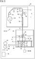
- FIG. 5 is a schematic diagram of the main machine body 16, showing a state in which the tip of the wire electrode 12 touches the exterior of the lower nozzle 32 and the wire electrode 12 bends when the workpiece 14 is thin (less than 150 [mm]).
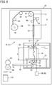
- FIG. 6 is a schematic diagram of the main machine body 16, showing a state in which the tip of the wire electrode 12 touches the exterior of the lower nozzle 32 and the wire electrode 12 bends when the workpiece 14 is thick (150 [mm] or more).
- the length, designated at A, of the wire electrode 12 between the brake roller 52 and the flexure detector 72 is greater than the length, designated at B, of the wire electrode 12 between the upper wire guide 24 and the lower wire guide 26, as shown in FIG. 5 . Therefore, the wire electrode 12 is prone to bend between the guide roller 56 and the AWF pipe 58. In this case, the flexure detector 72 can detect the bending of the wire electrode 12.
- the length A of the wire electrode 12 between the brake roller 52 and the flexure detector 72 is shorter than the length, designated at C, of the wire electrode 12 between the upper wire guide 24 and the lower wire guide 26, as shown in FIG. 6 . Therefore, the wire electrode 12 is prone to bend between the upper wire guide 24 and the lower wire guide 26. In this case, the flexure detector 72 cannot detect the bending of the wire electrode 12.
- the contact detector 76 in the lower nozzle 32 can detect abutment of the tip of the wire electrode 12 against the exterior of the lower nozzle 32.
- the wire electrode 12 may move along the exterior of the lower nozzle 32 and move downward below the lower wire guide 26 in some cases. In this case, since the wire electrode 12 does not bend, it is impossible for the controller 18 to detect a failure of auto wire feeding from the detection signal of the flexure detector 72. On the other hand, since the contact detector 76 of the lower nozzle 32 can detect that the wire electrode 12 is in contact with the exterior of the lower nozzle 32, the controller 18 can determine that auto wire feeding has failed from the detection signal of the contact detector 76.
- the controller 18 determines a failure of auto wire feeding without using the contact detector 76, when the flexure detector 72 cannot detect bending of the wire electrode 12. That is, if no detection signal is received from the AWF detector 78 even when the wire electrode 12 has been fed a predetermined length or more from the bobbin 40 after start of auto wire feeding, the controller 18 determine that the auto wire feeding has failed.
- the predetermined length may be designated in conformity with the length from the upper wire guide 24 to the AWF detector 78 on the running path of the wire electrode 12.
- the controller 18 can determine failure of auto wire feeding when the wire electrode 12 touches the exterior of the lower nozzle 32, based on the detection signal from the contact detector 76. Thus, it is possible to shorten the rewinding length of the wire electrode 12.
- the present embodiment is configured such that when the contact detector 76 detects contact of the wire electrode 12 with the exterior of the lower nozzle 32, the wire electrode 12 is rewound until the contact detector 76 no longer detects contact of the wire electrode 12 with the exterior of the lower nozzle 32.
- rewinding of the wire electrode 12 is performed until the tip of the wire electrode 12 is returned to a position just before the insertion position of the wire electrode 12 into the nozzle hole of the lower nozzle 32, so that the rewinding length of the wire electrode 12 can be shortened.
- the tip of the wire electrode 12 can be positioned near the nozzle hole of the lower nozzle 32, where the suction force into the lower nozzle 32 is strong. Therefore, the tip of the wire electrode 12 can be guided along the flow of working fluid toward the nozzle hole of the lower nozzle 32, and thus the success rate of auto wire feeding can be improved.
- the present embodiment is configured such that when the contact detector 76 detects contact of the wire electrode 12 with the exterior of the lower nozzle 32, a predetermined length of the wire electrode 12 is rewound. Thereby, it is possible to shorten the rewinding time of the wire electrode 12.
- FIG. 7 is a flowchart showing the flow of an auto wire feeding process in the controller 18. The flow of processing from step S1 to step S11 is the same as that described with reference to the flowcharts of FIGS. 2 and 3 in the first embodiment.
- step S12 the controller 18 drives the motor 46, the motor 54 and the motor 70 to start auto wire feeding of the wire electrode 12, and the control advances to step S21.
- the controller 18 determines whether or not the wire electrode 12 is subjected to bending, based on the presence or absence of a detection signal from the flexure detector 72, or determines whether or not the wire electrode 12 is in contact with the exterior of the lower nozzle 32, based on the presence or absence of a detection signal from the contact detector 76. If the wire electrode 12 is subjected to bending or the wire electrode 12 is in contact with the exterior of the lower nozzle 32, the control proceeds to step S14. When the wire electrode 12 is neither subjected to bending nor in contact with the exterior of the lower nozzle 32, the control proceeds to step S18.
- step S14 the controller 18 drives the motor 46 and the motor 54 to rewind the wire electrode 12, and the control proceeds to step S22.
- the controller 18 determines whether or not the wire electrode 12 is subjected to bending, based on the presence or absence of a detection signal from the flexure detector 72 or determines whether or not the wire electrode 12 is in contact with the exterior of the lower nozzle 32, based on the presence or absence of a detection signal from the contact detector 76. If the wire electrode 12 is subjected to bending or the wire electrode 12 is in contact with the exterior of the lower nozzle 32, the control returns to step S14. When the wire electrode 12 is neither subjected to bending nor in contact with the exterior of the lower nozzle 32, the control proceeds to step S16.
- step S16 to step S18 is the same as the processing flow described with reference to the flowcharts of FIGS. 2 and 3 in the first embodiment.
- FIGS. 8 and 9 are flowcharts showing the flow of an auto wire feeding process in the controller 18.
- step S5 the controller 18 drives the motor 46 and the motor 54 to rewind the wire electrode 12, and the control proceeds to step S31.
- the controller 18 determines whether or not the wire electrode 12 is out of contact with the exterior of the lower nozzle 32, based on the presence or absence of a detection signal from the contact detector 76, or determines whether or not a predetermined length of the wire electrode 12 has been rewound, based on the amount of rewinding of the motor 54 of the brake roller 52.
- the control proceeds to step S7.
- the control returns to step S5.
- step S14 the controller 18 drives the motor 46 and the motor 54 to rewind the wire electrode 12, and the control proceeds to step S32.
- the controller 18 determines whether or not a predetermined length of the wire electrode 12 has been rewound, based on the amount of rewinding of the motor 54 of the brake roller 52. When a predetermined length of the wire electrode 12 has been rewound, the control proceeds to step S16. When a predetermined length of the wire electrode 12 has not yet been rewound, the control returns to step S14.
- step S16 to step S18 is the same as the processing flow described with reference to the flowcharts of FIGS. 2 and 3 in the first embodiment.
- the wire electrical discharge machine (10) includes: the work-pan (20) configured to store working fluid; the table (22) disposed in the work-pan (20), the workpiece (14) being placed on the table (22); the lower nozzle (32) disposed under the table (22) and having the nozzle hole into which the wire electrode (12) is inserted; the contact detector (76) disposed at the lower nozzle (32) and configured to detect contact of the wire electrode (12) with the exterior of the lower nozzle (32); the suction unit (38) configured to suction working fluid into the lower nozzle (32); and the wire feeding mechanism (45) configured to pass the wire electrode (12) through the machining hole in the workpiece (14) and feed the wire electrode (12) toward the lower nozzle (32).
- the auto wire feeding method may include the steps of: when auto wire feeding is performed with the work-pan (20) containing working fluid, feeding the wire electrode (12) toward the lower nozzle (32) by the wire feeding mechanism (45) while suctioning the working fluid into the lower nozzle (32) by the suction unit (38); and rewinding the wire electrode (12) by the wire feeding mechanism (45) when the contact detector (76) detects contact of the wire electrode (12) with the exterior of the lower nozzle (32).
- the wire electrode (12) when the thickness of the workpiece (14) is 150 [mm] or more and when auto wire feeding is performed with the work-pan (20) containing working fluid, the wire electrode (12) may be fed toward the lower nozzle (32) by the wire feeding mechanism (45) while the suction unit (38) may suction the working fluid into the lower nozzle (32), and the wire electrode (12) may be rewound by the wire feeding mechanism (45) when the contact detector (76) detects contact of the wire electrode (12) with the exterior of the lower nozzle (32). This makes it possible to shorten the time required to complete the auto wire feeding of the wire electrode (12).
- the wire electrode (12) when the thickness of the workpiece (14) is 200 [mm] or more and when auto wire feeding is performed with the work-pan (20) containing working fluid, the wire electrode (12) may be fed toward the lower nozzle (32) by the wire feeding mechanism (45) while the suction unit (38) may suction the working fluid into the lower nozzle (32), and the wire electrode (12) may be rewound by the wire feeding mechanism (45) when the contact detector (76) detects contact of the wire electrode (12) with the exterior of the lower nozzle (32). This makes it possible to shorten the time required to complete the auto wire feeding of the wire electrode (12).
- the contact detector (76) detects contact of the wire electrode (12) with the exterior of the lower nozzle (32)
- the wire electrode (12) may be rewound until the contact detector (76) no longer detects contact of the wire electrode (12) with the exterior of the lower nozzle (32).
- a predetermined length of the wire electrode (12) may be rewound when the contact detector (76) detects contact of the wire electrode (12) with the exterior of the lower nozzle (32). Thereby, it is possible to shorten the rewinding time of the wire electrode (12).
- the wire electrical discharge machine (10) includes: the work-pan (20) configured to store working fluid; the table (22) disposed in the work-pan (20), a workpiece (14) being placed on the table (22); the lower nozzle (32) disposed under the table (22) and having the nozzle hole into which the wire electrode (12) is inserted; the contact detector (76) disposed at the lower nozzle (32) and configured to detect contact of the wire electrode (12) with the exterior of the lower nozzle (32); the suction unit (38) configured to suction working fluid into the lower nozzle (32); the wire feeding mechanism (45) configured to pass the wire electrode (12) through the machining hole in the workpiece (14) and feed the wire electrode (12) toward the lower nozzle (32); and the auto wire feeding control unit (19) configured to, when auto wire feeding is performed with the work-pan (20) containing working fluid, control the wire feeding mechanism (45) to feed the wire electrode (12) toward the lower nozzle (32) while controlling the suction unit (38) to suction the working fluid into the lower nozzle (32), and further configured to
- the above wire electrical discharge machine (10) may be configured such that, when the contact detector (76) detects contact of the wire electrode (12) with the exterior of the lower nozzle (32), the auto wire feeding control unit (19) controls the wire feeding mechanism (45) to rewind the wire electrode (12) until the contact detector (76) no longer detects contact of the wire electrode (12) with the exterior of the lower nozzle (32). As a result, it is possible to shorten the time required to complete the auto wire feeding of the wire electrode (12).
Landscapes
- Engineering & Computer Science (AREA)
- Mechanical Engineering (AREA)
- Chemical & Material Sciences (AREA)
- Chemical Kinetics & Catalysis (AREA)
- Electrochemistry (AREA)
- Manufacturing & Machinery (AREA)
- Electrical Discharge Machining, Electrochemical Machining, And Combined Machining (AREA)
Abstract
A wire electrical discharge machine (10) includes a contact detector (76) provided at a lower nozzle (32) and configured to detect contact of a wire electrode (12) with the exterior of the lower nozzle (32), a suction unit (38) configured to suction working fluid into the lower nozzle (32), and a wire feeding mechanism (45) configured to pass the wire electrode (12) through a machining hole in a workpiece (14) and feed the wire electrode (12) toward the lower nozzle (32). When auto wire feeding is performed with a work-pan (20) containing working fluid, the wire electrode (12) is fed toward the lower nozzle (32) by the wire feeding mechanism (45) while the suction unit (38) suctions the working fluid into the lower nozzle (32). When the contact detector (76) detects contact of the wire electrode (12) with the exterior of the lower nozzle (32), the wire electrode (12) is rewound by the wire feeding mechanism (45) .
Description
- The present invention relates to an auto wire feeding method for automatically feeding a wire electrode, as well as relating to a wire electrical discharge machine. Description of the Related Art:
Japanese Laid-Open Patent Publication No.58-177234 - In the technology disclosed in Japanese Laid-Open Patent Publication No.
58-177234 - The present invention has been devised to solve the above problem, and it is therefore an object of the present invention to provide an auto wire feeding method and a wire electrical discharge machine capable of shortening the time required for completion of auto feeding of a wire electrode and improving the success rate of auto wire feeding.
- An aspect of the present invention resides in an auto wire feeding method for performing auto wire feeding of a wire electrode in a wire electrical discharge machine. The wire electrical discharge machine includes: a work-pan configured to store working fluid; a table disposed in the work-pan, a workpiece being placed on the table; a lower nozzle disposed under the table and having a nozzle hole into which the wire electrode is inserted; a contact detector disposed at the lower nozzle and configured to detect contact of the wire electrode with the exterior of the lower nozzle; a suction unit configured to suction working fluid into the lower nozzle; and a wire feeding mechanism configured to pass the wire electrode through a machining hole in the workpiece and feed the wire electrode toward the lower nozzle. The auto wire feeding method includes the steps of: when auto wire feeding is performed with the work-pan containing working fluid, feeding the wire electrode toward the lower nozzle by the wire feeding mechanism while suctioning the working fluid into the lower nozzle by the suction unit; and rewinding the wire electrode by the wire feeding mechanism when the contact detector detects contact of the wire electrode with the exterior of the lower nozzle.
- According to the present invention, it is possible to shorten the time required to complete the auto wire feeding of the wire electrode.
- The above and other objects, features, and advantages of the present invention will become more apparent from the following description when taken in conjunction with the accompanying drawings in which a preferred embodiment of the present invention is shown by way of illustrative example.
-
-
FIG. 1 is a schematic diagram of a wire electrical discharge machine; -
FIG. 2 is a flowchart showing the flow of an auto wire feeding process performed by a controller; -
FIG. 3 is a flowchart showing the flow of the auto wire feeding process performed by the controller; -
FIG. 4 is a graph showing the relationship between the thickness of a workpiece and the success rate of auto wire feeding; -
FIG. 5 is a schematic diagram of the wire electrical discharge machine showing a state in which a tip of a wire electrode touches the exterior of a lower nozzle and the wire electrode bends; -
FIG. 6 is a schematic diagram of the wire electrical discharge machine showing a state in which the tip of the wire electrode touches the exterior of the lower nozzle and the wire electrode bends; -
FIG. 7 is a flowchart showing the flow of an auto wire feeding process performed by the controller; -
FIG. 8 is a flowchart showing the flow of the auto wire feeding process performed by the controller; and -
FIG. 9 is a flowchart showing the flow of the auto wire feeding process performed by the controller. -
FIG. 1 is a schematic diagram of a wireelectrical discharge machine 10. The wireelectrical discharge machine 10 is a machine tool for performing electrical discharge machining on aworkpiece 14 by applying voltage between awire electrode 12 and theworkpiece 14 to thereby generate electrical discharge. Thewire electrode 12 is formed of, for example, metal material such as tungsten-based, copper-alloy based and brass-based material. On the other hand, the material of theworkpiece 14 is metal material such as iron-based material or superhard material (tungsten carbide). - The wire
electrical discharge machine 10, at least, includes amain machine body 16 and acontroller 18. Themain machine body 16 is provided with a work-pan 20 capable of storing a dielectric working fluid (hereinafter simply referred to as a working fluid) such as deionized water or oil used for electrical discharge machining on theworkpiece 14. The work-pan 20 contains therein a table 22 on which theworkpiece 14 is fixed. The work-pan 20 is movable on a horizontal plane by an unillustrated servo motor. As the work-pan 20 is moved, theworkpiece 14 fixed on the table 22 moves relative to thewire electrode 12 accordingly. By performing electrical discharge machining on theworkpiece 14 while moving the workpiece relative to thewire electrode 12, it is possible to machine theworkpiece 14 into a desired shape. - The
main machine body 16 has anupper wire guide 24 and alower wire guide 26. Theupper wire guide 24 is arranged above theworkpiece 14, and thelower wire guide 26 is arranged under theworkpiece 14. Theupper wire guide 24 has anupper nozzle 28 for ejecting a working fluid through a nozzle hole thereof into which thewire electrode 12 is inserted, and anupper electrode pin 30 through which electric power is supplied to thewire electrode 12. Thelower wire guide 26 has alower nozzle 32 for suctioning and ejecting a working fluid through a nozzle hole thereof into which thewire electrode 12 is inserted, and alower electrode pin 34 through which electric power is supplied to thewire electrode 12. - The
upper nozzle 28 and thelower nozzle 32 are connected to apump 36 which is driven under control of thecontroller 18. Thepump 36 supplies a working fluid into the interior of theupper nozzle 28 and thelower nozzle 32 and suctions a working fluid into thelower nozzle 32. Thepump 36 constitutes asuction unit 38. - The
main machine body 16 has arunning mechanism 44 for feeding thewire electrode 12 from abobbin 40 through the machining hole of theworkpiece 14 to acollecting box 42. Therunning mechanism 44 includes, in order from the upstream side in the running direction of thewire electrode 12, thebobbin 40, aguide roller 48, aguide roller 50, abrake roller 52, aguide roller 56, an auto wire feeding (AWF)pipe 58, theupper wire guide 24, thelower wire guide 26, aguide roller 62, alower pipe 64, apinch roller 66 and afeed roller 68. Thisrunning mechanism 44 defines a running path of thewire electrode 12. Therunning mechanism 44 constitutes awire feeding mechanism 45. - The
bobbin 40 is rotated by a torque applied from amotor 46 which is driven under control of thecontroller 18. Along wire electrode 12 is wound on thebobbin 40, and thewire electrode 12 is supplied or fed from thebobbin 40 as thebobbin 40 rotates. - The
wire electrode 12 supplied from thebobbin 40 is extended on and along theguide roller 48 and theguide roller 50. Theguide roller 48 and theguide roller 50 change the running direction of thewire electrode 12 fed out from thebobbin 40, and guide thewire electrode 12 toward thebrake roller 52. - The
brake roller 52 is rotated by a torque applied from amotor 54 which is driven under control of thecontroller 18. Thebrake roller 52 can feed thewire electrode 12 without slipping, and it is possible to apply a braking force to thewire electrode 12 by adjusting the torque applied from themotor 46 to thebrake roller 52. - The
wire electrode 12 sent from thebrake roller 52 is extended on theguide roller 56 and then sent to the AWFpipe 58. Atension detector 60 is disposed between thebrake roller 52 and theguide roller 56. Thetension detector 60 is a sensor for detecting the tension of thewire electrode 12. Thewire electrode 12 sent to the AWFpipe 58 passes therethrough and is sent to theupper wire guide 24. Thewire electrode 12 sent to theupper wire guide 24 passes through the machining hole of theworkpiece 14 and is sent to thelower wire guide 26. - The
wire electrode 12 sent to thelower wire guide 26 is extended over theguide roller 62 provided in thelower wire guide 26 and then sent to thelower pipe 64. Thewire electrode 12 sent to thelower pipe 64, after passing through thelower pipe 64, is sent into thecollecting box 42 by thepinch roller 66 and thefeed roller 68 that hold and sandwich thewire electrode 12 therebetween. Thefeed roller 68 is rotated by a torque applied from amotor 70 which is driven under control of thecontroller 18. - When the
wire electrode 12 is subjected to breakage during electrical discharge machining on theworkpiece 14, therunning mechanism 44 automatically feeds the wire electrode 12 (auto wire feeding). Auto wire feeding is performed in a state in which the working fluid is stored in the work-pan 20. When the auto wire feeding fails, thewire electrode 12 is rewound, and thewire electrode 12 is then automatically fed again. As a sensor for detecting failures of auto wire feeding, in the present embodiment, aflexure detector 72 and acontact detector 76 are provided in themain machine body 16. - During the auto wire feeding, the tip of the
wire electrode 12 travels on path segments without guiding action of the guides or the rollers. Of the segments, a segment between theupper nozzle 28 and thelower nozzle 32 is the longest. Therefore, when thewire electrode 12 is fed from theupper nozzle 28 toward thelower nozzle 32, failure of auto wire feeding tends to occur due to the tip of thewire electrode 12 deviating from the nozzle hole of thelower nozzle 32. - The
flexure detector 72 is disposed between theguide roller 56 and theAWF pipe 58, and is a sensor for detecting bending of thewire electrode 12 that is caused when the tip of thewire electrode 12 deviates from the nozzle hole of thelower nozzle 32 and touches the exterior of thelower nozzle 32. Thecontact detector 76 is disposed on thelower nozzle 32, and is a sensor for detecting contact of thewire electrode 12 with the exterior of thelower nozzle 32. - In the present embodiment, an
AWF detector 78 is provided as a sensor for detecting completion of auto wire feeding. TheAWF detector 78 is disposed between the collectingbox 42 and thepinch roller 66 andfeed roller 68, and is a sensor for detecting arrival of the tip of thewire electrode 12 at the position of theAWF detector 78. - Next, description will be given concerning a process by the
controller 18 for performing auto wire feeding while the working fluid resides in the work-pan 20 when thewire electrode 12 is subjected to breakage during electrical discharge machining on theworkpiece 14. When theworkpiece 14 is thick, thecontroller 18 controls thepump 36 and the runningmechanism 44 to thereby perform auto wire feeding while suctioning the working fluid through thelower nozzle 32. - When the thickness of the
workpiece 14 is 150 [mm] or more, thecontroller 18 determines that theworkpiece 14 is thick. When the thickness of theworkpiece 14 is less than 150 [mm], thecontroller 18 determines that theworkpiece 14 is thin. The thickness of theworkpiece 14 is input to thecontroller 18 by the operator operating an input device or the like, before the electrical discharge machining on theworkpiece 14 is started. Alternatively, a thickness measuring mechanism for automatically measuring the thickness of theworkpiece 14 may be provided so that the thickness of theworkpiece 14 is input from the thickness measuring mechanism to thecontroller 18. Thecontroller 18 constitutes an auto wirefeeding control unit 19. -
FIGS. 2 and3 are flowcharts showing the flow of auto wire feeding process in thecontroller 18. At step S1, thecontroller 18 determines whether or not the thickness of theworkpiece 14 is thick. If theworkpiece 14 is thick, the control proceeds to step S2, and if theworkpiece 14 is thin, the control goes to step S12. - At step S2, the
controller 18 drives themotor 46, themotor 54 and themotor 70 to start auto wire feeding of thewire electrode 12, and the control proceeds to step S3. At step S3, thecontroller 18 drives thepump 36 to suction a working fluid through thelower nozzle 32, and the control proceeds to step S4. - At step S4, the
controller 18 determines whether or not thewire electrode 12 touches the exterior of thelower nozzle 32, based on the presence or absence of a detection signal from thecontact detector 76. Thecontroller 18 determines that the auto wire feeding has failed, by receiving the detection signal from thecontact detector 76. When thewire electrode 12 is in contact with the exterior of thelower nozzle 32, the control proceeds to step S5. When thewire electrode 12 is not in contact with the exterior of thelower nozzle 32, the control goes to step S9. - At step S5, the
controller 18 drives themotor 46 and themotor 54 to rewind thewire electrode 12, and the control proceeds to step S6. At step S6, thecontroller 18 determines whether or not thewire electrode 12 is in contact with the exterior of thelower nozzle 32, based on the presence or absence of a detection signal from thecontact detector 76. If thewire electrode 12 is in contact with the exterior of thelower nozzle 32, the control returns to step S5. If thewire electrode 12 is not in contact with the exterior of thelower nozzle 32, the control goes to step S7. - At step S7, the
controller 18 stops themotor 46 and themotor 54 to stop rewinding thewire electrode 12, and the control proceeds to step S8. At step S8, thecontroller 18 drives themotor 46, themotor 54 and themotor 70 to restart the auto wire feeding of thewire electrode 12, and the control proceeds to step S9. At step S9, thecontroller 18 determines whether or not the auto wire feeding of thewire electrode 12 is completed, based on the presence or absence of a detection signal from theAWF detector 78. When the auto wire feeding of thewire electrode 12 is completed, the control proceeds to step S10, and when the auto wire feeding of thewire electrode 12 has not yet been completed, the control returns to step S4. - At step S10, the
controller 18 stops thepump 36 to complete suctioning of a working fluid through thelower nozzle 32, and the control proceeds to step S11. At step S11, thecontroller 18 stops themotor 46, themotor 54 and themotor 70, terminates the auto wire feeding of thewire electrode 12, and ends the auto wire feeding process. At step S11, electrical discharge machining may be subsequently performed without stopping themotor 46, themotor 54 and themotor 70. - At step S12, the
controller 18 drives themotor 46, themotor 54 and themotor 70 to start auto wire feeding of thewire electrode 12, and the control proceeds to step S13. At step S13, thecontroller 18 determines whether or not bending occurs in thewire electrode 12, based on the presence or absence of a detection signal from theflexure detector 72. Thecontroller 18 determines that auto wire feeding has failed, by receiving the detection signal from theflexure detector 72. When bending occurs in thewire electrode 12, the control proceeds to step S14. When no bending is occurring in thewire electrode 12, the control goes to step S18. - At step S14, the
controller 18 drives themotor 46 and themotor 54 to rewind thewire electrode 12, and the control proceeds to step S15. At step S15, thecontroller 18 determines whether or not bending occurs in thewire electrode 12, based on the presence or absence of a detection signal from theflexure detector 72. When bending occurs in thewire electrode 12, the control returns to step S14. When no bending is occurring in thewire electrode 12, the control goes to step S16. - At step S16, the
controller 18 stops themotor 46 and themotor 54 to stop rewinding of thewire electrode 12, and the control proceeds to step S17. At step S17, thecontroller 18 drives themotor 46, themotor 54 and themotor 70 to restart auto wire feeding of thewire electrode 12, and the control proceeds to step S18. At step S18, thecontroller 18 determines whether or not the wire feeding of thewire electrode 12 is completed, based on the presence or absence of a detection signal from theAWF detector 78. When the wire feeding of thewire electrode 12 is completed, the control proceeds to step S11, and when the wire feeding of thewire electrode 12 has not yet been completed, the control returns to step S13. - It is noted that the
controller 18 may be configured to determine that theworkpiece 14 is thick when the thickness of theworkpiece 14 is 200 [mm] or more and that theworkpiece 14 is thin when the thickness of theworkpiece 14 is less than 200 [mm]. Further, thecontroller 18 may be configured to determine that theworkpiece 14 is thick when the thickness of theworkpiece 14 is 250 [mm] or more and that theworkpiece 14 is thin when the thickness of theworkpiece 14 is less than 250 [mm]. Furthermore, thecontroller 18 may be configured to determine that theworkpiece 14 is thick when the thickness of theworkpiece 14 is 300 [mm] or more and that theworkpiece 14 is thin when the thickness of theworkpiece 14 is less than 300 [mm]. - In the above embodiment, it is determined at step S1 whether the
workpiece 14 is thick or thin, and the process of steps S2 to S9 and the process of step S12 to step S18 are executed separately, depending on the thickness. However, only the process from step S2 to step S9 may be performed regardless of the workpiece thickness. - In a state that the working fluid has been discharged from the work-
pan 20, the working fluid is supplied to theupper nozzle 28 by thepump 36 and then ejected from the nozzle hole of theupper nozzle 28, and thewire electrode 12 is fed. In this case, the straightness of thewire electrode 12 is enhanced so that the success rate of auto wire feeding can be improved. However, when thewire electrode 12 is broken during electrical discharge machining on theworkpiece 14, if auto wire feeding is performed with the working fluid having been discharged from the work-pan 20, it is necessary to discharge and supply the working fluid before and after auto wire feeding, which takes a long time until restart of electrical discharge machining. To deal with this, in the present embodiment, auto wire feeding is performed with the work-pan 20 containing therein the working fluid, aiming at shortening the time required until restart of electrical discharge machining. - In the case where auto wire feeding is performed with the work-
pan 20 containing therein the working fluid, auto wire feeding is more likely to fail than the case where auto wire feeing is performed with the working fluid emptied from the work-pan 20. This is because even if thewire electrode 12 is advanced while working fluid is ejected from the nozzle hole of theupper nozzle 28, the flow of working fluid from the nozzle hole of theupper nozzle 28 quickly slows in the working fluid, so that the straightness of thewire electrode 12 cannot be sufficiently enhanced. In addition, this is also because thewire electrode 12 easily floats due to buoyancy in the working fluid. - In the present embodiment, in order to shorten the time required for completing the auto wire feeding in the case where auto wire feeding is performed with working fluid stored in the work-
pan 20, the success rate of the auto wire feeding is improved while the rewinding length of thewire electrode 12 at the time of unsuccessful auto wire feeding is shortened. -
FIG. 4 is a graph showing the relationship between the thickness of theworkpiece 14 and the success rate of auto wire feeding.FIG. 4 shows the success rate of auto wire feeding performed when the working fluid is stored in the work-pan 20 without any suction of working fluid from thelower nozzle 32. As shown inFIG. 4 , as the thickness of theworkpiece 14 becomes thicker, the distance between theupper nozzle 28 and thelower nozzle 32 becomes longer, so that the success rate of auto wire feeding decreases accordingly. Further, as the diameter of thewire electrode 12 becomes smaller, the straightness of thewire electrode 12 that is fed from theupper nozzle 28 becomes worse, so that the success rate of auto wire feeding decreases accordingly. - As shown in
FIG. 4 , regardless of the diameter of thewire electrode 12, when the thickness of theworkpiece 14 is 150 [mm] or more, the success rate of auto wire feeding decreases, compared to when the thickness is less than 150 [mm]. Based on this, in the present embodiment, when the thickness of theworkpiece 14 is 150 [mm] or more, auto wire feeding is performed while working fluid is drawn into thelower nozzle 32 by thepump 36. As a result, the tip of thewire electrode 12 sent from theupper nozzle 28 can be guided to the nozzle hole of thelower nozzle 32 along the flow of working fluid toward the nozzle hole of thelower nozzle 32, and hence the success rate of auto wire feeding can be improved. - When the thickness of the
workpiece 14 is large (150 [mm] or more), cases occur where theflexure detector 72 cannot detect bending of thewire electrode 12 caused by abutment against the exterior of thelower nozzle 32. -
FIG. 5 is a schematic diagram of themain machine body 16, showing a state in which the tip of thewire electrode 12 touches the exterior of thelower nozzle 32 and thewire electrode 12 bends when theworkpiece 14 is thin (less than 150 [mm]).FIG. 6 is a schematic diagram of themain machine body 16, showing a state in which the tip of thewire electrode 12 touches the exterior of thelower nozzle 32 and thewire electrode 12 bends when theworkpiece 14 is thick (150 [mm] or more). - When auto wire feeding fails and the tip of the
wire electrode 12 abuts against the exterior of thelower nozzle 32, movement of the tip of thewire electrode 12 is restricted, and as a result, thewire electrode 12 bends when thewire electrode 12 continues to be fed from thebobbin 40. Thewire electrode 12 is likely to bend in a longer one of the segments of thewire electrode 12 between two adjacent support points supporting thewire electrode 12. - When the
workpiece 14 is thin (less than 150 [mm]), the length, designated at A, of thewire electrode 12 between thebrake roller 52 and theflexure detector 72 is greater than the length, designated at B, of thewire electrode 12 between theupper wire guide 24 and thelower wire guide 26, as shown inFIG. 5 . Therefore, thewire electrode 12 is prone to bend between theguide roller 56 and theAWF pipe 58. In this case, theflexure detector 72 can detect the bending of thewire electrode 12. - When the
workpiece 14 is thick (150 [mm] or more), the length A of thewire electrode 12 between thebrake roller 52 and theflexure detector 72 is shorter than the length, designated at C, of thewire electrode 12 between theupper wire guide 24 and thelower wire guide 26, as shown inFIG. 6 . Therefore, thewire electrode 12 is prone to bend between theupper wire guide 24 and thelower wire guide 26. In this case, theflexure detector 72 cannot detect the bending of thewire electrode 12. - However, in the present embodiment, even if the bending of the
wire electrode 12 cannot be detected by theflexure detector 72, thecontact detector 76 in thelower nozzle 32 can detect abutment of the tip of thewire electrode 12 against the exterior of thelower nozzle 32. - Further, when the tip of the
wire electrode 12 deviates from the nozzle hole of thelower nozzle 32, thewire electrode 12 may move along the exterior of thelower nozzle 32 and move downward below thelower wire guide 26 in some cases. In this case, since thewire electrode 12 does not bend, it is impossible for thecontroller 18 to detect a failure of auto wire feeding from the detection signal of theflexure detector 72. On the other hand, since thecontact detector 76 of thelower nozzle 32 can detect that thewire electrode 12 is in contact with the exterior of thelower nozzle 32, thecontroller 18 can determine that auto wire feeding has failed from the detection signal of thecontact detector 76. - It should be noted that it is possible for the
controller 18 to determine a failure of auto wire feeding without using thecontact detector 76, when theflexure detector 72 cannot detect bending of thewire electrode 12. That is, if no detection signal is received from theAWF detector 78 even when thewire electrode 12 has been fed a predetermined length or more from thebobbin 40 after start of auto wire feeding, thecontroller 18 determine that the auto wire feeding has failed. The predetermined length may be designated in conformity with the length from theupper wire guide 24 to theAWF detector 78 on the running path of thewire electrode 12. - However, in this case, there is a concern that it takes long time to complete auto wire feeding because the length of the
wire electrode 12 to be rewound becomes long. In the present embodiment, thecontroller 18 can determine failure of auto wire feeding when thewire electrode 12 touches the exterior of thelower nozzle 32, based on the detection signal from thecontact detector 76. Thus, it is possible to shorten the rewinding length of thewire electrode 12. - Further, the present embodiment is configured such that when the
contact detector 76 detects contact of thewire electrode 12 with the exterior of thelower nozzle 32, thewire electrode 12 is rewound until thecontact detector 76 no longer detects contact of thewire electrode 12 with the exterior of thelower nozzle 32. As a result, rewinding of thewire electrode 12 is performed until the tip of thewire electrode 12 is returned to a position just before the insertion position of thewire electrode 12 into the nozzle hole of thelower nozzle 32, so that the rewinding length of thewire electrode 12 can be shortened. In addition, the tip of thewire electrode 12 can be positioned near the nozzle hole of thelower nozzle 32, where the suction force into thelower nozzle 32 is strong. Therefore, the tip of thewire electrode 12 can be guided along the flow of working fluid toward the nozzle hole of thelower nozzle 32, and thus the success rate of auto wire feeding can be improved. - Further, the present embodiment is configured such that when the
contact detector 76 detects contact of thewire electrode 12 with the exterior of thelower nozzle 32, a predetermined length of thewire electrode 12 is rewound. Thereby, it is possible to shorten the rewinding time of thewire electrode 12. - In
Modification 1, the procedures at steps S13 and S15 inFIG. 3 of the first embodiment are replaced by procedures of steps S21 and S22 as described later.FIG. 7 is a flowchart showing the flow of an auto wire feeding process in thecontroller 18. The flow of processing from step S1 to step S11 is the same as that described with reference to the flowcharts ofFIGS. 2 and3 in the first embodiment. - At step S12, the
controller 18 drives themotor 46, themotor 54 and themotor 70 to start auto wire feeding of thewire electrode 12, and the control advances to step S21. - At step S21, the
controller 18 determines whether or not thewire electrode 12 is subjected to bending, based on the presence or absence of a detection signal from theflexure detector 72, or determines whether or not thewire electrode 12 is in contact with the exterior of thelower nozzle 32, based on the presence or absence of a detection signal from thecontact detector 76. If thewire electrode 12 is subjected to bending or thewire electrode 12 is in contact with the exterior of thelower nozzle 32, the control proceeds to step S14. When thewire electrode 12 is neither subjected to bending nor in contact with the exterior of thelower nozzle 32, the control proceeds to step S18. - At step S14, the
controller 18 drives themotor 46 and themotor 54 to rewind thewire electrode 12, and the control proceeds to step S22. - At step S22, the
controller 18 determines whether or not thewire electrode 12 is subjected to bending, based on the presence or absence of a detection signal from theflexure detector 72 or determines whether or not thewire electrode 12 is in contact with the exterior of thelower nozzle 32, based on the presence or absence of a detection signal from thecontact detector 76. If thewire electrode 12 is subjected to bending or thewire electrode 12 is in contact with the exterior of thelower nozzle 32, the control returns to step S14. When thewire electrode 12 is neither subjected to bending nor in contact with the exterior of thelower nozzle 32, the control proceeds to step S16. - The processing flow from step S16 to step S18 is the same as the processing flow described with reference to the flowcharts of
FIGS. 2 and3 in the first embodiment. - In
Modification 2, the procedures at step S6 inFIG. 2 and step S15 inFIG. 3 of the first embodiment are replaced by procedures of step S31 and step S32 as described later.FIGS. 8 and9 are flowcharts showing the flow of an auto wire feeding process in thecontroller 18. - The processing flow at steps S1 to S4 is the same as that described with reference to the flowcharts of
FIGS. 2 and3 in the first embodiment. At step S5, thecontroller 18 drives themotor 46 and themotor 54 to rewind thewire electrode 12, and the control proceeds to step S31. - At step S31, the
controller 18 determines whether or not thewire electrode 12 is out of contact with the exterior of thelower nozzle 32, based on the presence or absence of a detection signal from thecontact detector 76, or determines whether or not a predetermined length of thewire electrode 12 has been rewound, based on the amount of rewinding of themotor 54 of thebrake roller 52. When thewire electrode 12 is out of contact with the exterior of thelower nozzle 32 or when a predetermined length of thewire electrode 12 has been rewound, the control proceeds to step S7. When thewire electrode 12 is in contact with the exterior of thelower nozzle 32 and a predetermined length of thewire electrode 12 has not yet been rewound, the control returns to step S5. - The processing flow from step S7 to step S13 is the same as the processing flow described with reference to the flowcharts of
FIGS. 2 and3 in the first embodiment. At step S14, thecontroller 18 drives themotor 46 and themotor 54 to rewind thewire electrode 12, and the control proceeds to step S32. - At step S32, the
controller 18 determines whether or not a predetermined length of thewire electrode 12 has been rewound, based on the amount of rewinding of themotor 54 of thebrake roller 52. When a predetermined length of thewire electrode 12 has been rewound, the control proceeds to step S16. When a predetermined length of thewire electrode 12 has not yet been rewound, the control returns to step S14. - The processing flow from step S16 to step S18 is the same as the processing flow described with reference to the flowcharts of
FIGS. 2 and3 in the first embodiment. - Technical concepts that can be grasped from the above embodiment will be described below.
- In the auto wire feeding method for performing auto wire feeding of the wire electrode (12) in the wire electrical discharge machine (10), the wire electrical discharge machine (10) includes: the work-pan (20) configured to store working fluid; the table (22) disposed in the work-pan (20), the workpiece (14) being placed on the table (22); the lower nozzle (32) disposed under the table (22) and having the nozzle hole into which the wire electrode (12) is inserted; the contact detector (76) disposed at the lower nozzle (32) and configured to detect contact of the wire electrode (12) with the exterior of the lower nozzle (32); the suction unit (38) configured to suction working fluid into the lower nozzle (32); and the wire feeding mechanism (45) configured to pass the wire electrode (12) through the machining hole in the workpiece (14) and feed the wire electrode (12) toward the lower nozzle (32). The auto wire feeding method may include the steps of: when auto wire feeding is performed with the work-pan (20) containing working fluid, feeding the wire electrode (12) toward the lower nozzle (32) by the wire feeding mechanism (45) while suctioning the working fluid into the lower nozzle (32) by the suction unit (38); and rewinding the wire electrode (12) by the wire feeding mechanism (45) when the contact detector (76) detects contact of the wire electrode (12) with the exterior of the lower nozzle (32). With this method, it is possible to shorten the time required to complete the auto wire feeding of the wire electrode (12).
- In the above auto wire feeding method, when the thickness of the workpiece (14) is 150 [mm] or more and when auto wire feeding is performed with the work-pan (20) containing working fluid, the wire electrode (12) may be fed toward the lower nozzle (32) by the wire feeding mechanism (45) while the suction unit (38) may suction the working fluid into the lower nozzle (32), and the wire electrode (12) may be rewound by the wire feeding mechanism (45) when the contact detector (76) detects contact of the wire electrode (12) with the exterior of the lower nozzle (32). This makes it possible to shorten the time required to complete the auto wire feeding of the wire electrode (12).
- In the above auto wire feeding method, when the thickness of the workpiece (14) is 200 [mm] or more and when auto wire feeding is performed with the work-pan (20) containing working fluid, the wire electrode (12) may be fed toward the lower nozzle (32) by the wire feeding mechanism (45) while the suction unit (38) may suction the working fluid into the lower nozzle (32), and the wire electrode (12) may be rewound by the wire feeding mechanism (45) when the contact detector (76) detects contact of the wire electrode (12) with the exterior of the lower nozzle (32). This makes it possible to shorten the time required to complete the auto wire feeding of the wire electrode (12).
- In the above auto wire feeding method, when the contact detector (76) detects contact of the wire electrode (12) with the exterior of the lower nozzle (32), the wire electrode (12) may be rewound until the contact detector (76) no longer detects contact of the wire electrode (12) with the exterior of the lower nozzle (32). As a result, it is possible to shorten the time required to complete the auto wire feeding of the wire electrode (12).
- In the above auto wire feeding method, a predetermined length of the wire electrode (12) may be rewound when the contact detector (76) detects contact of the wire electrode (12) with the exterior of the lower nozzle (32). Thereby, it is possible to shorten the rewinding time of the wire electrode (12).
- The wire electrical discharge machine (10) includes: the work-pan (20) configured to store working fluid; the table (22) disposed in the work-pan (20), a workpiece (14) being placed on the table (22); the lower nozzle (32) disposed under the table (22) and having the nozzle hole into which the wire electrode (12) is inserted; the contact detector (76) disposed at the lower nozzle (32) and configured to detect contact of the wire electrode (12) with the exterior of the lower nozzle (32); the suction unit (38) configured to suction working fluid into the lower nozzle (32); the wire feeding mechanism (45) configured to pass the wire electrode (12) through the machining hole in the workpiece (14) and feed the wire electrode (12) toward the lower nozzle (32); and the auto wire feeding control unit (19) configured to, when auto wire feeding is performed with the work-pan (20) containing working fluid, control the wire feeding mechanism (45) to feed the wire electrode (12) toward the lower nozzle (32) while controlling the suction unit (38) to suction the working fluid into the lower nozzle (32), and further configured to, when the contact detector (76) detects contact of the wire electrode (12) with the exterior of the lower nozzle (32), control the wire feeding mechanism (45) to rewind the wire electrode (12). This configuration makes it possible to shorten the time required to complete the auto wire feeding of the wire electrode (12) .
- The above wire electrical discharge machine (10) may be configured such that, when the contact detector (76) detects contact of the wire electrode (12) with the exterior of the lower nozzle (32), the auto wire feeding control unit (19) controls the wire feeding mechanism (45) to rewind the wire electrode (12) until the contact detector (76) no longer detects contact of the wire electrode (12) with the exterior of the lower nozzle (32). As a result, it is possible to shorten the time required to complete the auto wire feeding of the wire electrode (12).
Claims (7)
- An auto wire feeding method for performing auto wire feeding of a wire electrode (12) in a wire electrical discharge machine (10),
the wire electrical discharge machine comprising:a work-pan (20) configured to store working fluid;a table (22) disposed in the work-pan, a workpiece (14) being placed on the table (22);a lower nozzle (32) disposed under the table and having a nozzle hole into which the wire electrode (12) is inserted;a contact detector (76) disposed at the lower nozzle and configured to detect contact of the wire electrode with an exterior of the lower nozzle;a suction unit (38) configured to suction working fluid into the lower nozzle; anda wire feeding mechanism (45) configured to pass the wire electrode through a machining hole in the workpiece and feed the wire electrode toward the lower nozzle,the auto wire feeding method comprising the steps of:when auto wire feeding is performed with the work-pan containing working fluid,feeding the wire electrode toward the lower nozzle by the wire feeding mechanism while suctioning the working fluid into the lower nozzle by the suction unit; andrewinding the wire electrode by the wire feeding mechanism when the contact detector detects contact of the wire electrode with the exterior of the lower nozzle. - The auto wire feeding method according to claim 1, wherein, when the thickness of the workpiece is 150 [mm] or more and when auto wire feeding is performed with the work-pan containing working fluid, the wire electrode is fed toward the lower nozzle by the wire feeding mechanism while the suction unit suctions the working fluid into the lower nozzle, and the wire electrode is rewound by the wire feeding mechanism when the contact detector detects contact of the wire electrode with the exterior of the lower nozzle.
- The auto wire feeding method according to claim 1, wherein, when the thickness of the workpiece is 200 [mm] or more and when auto wire feeding is performed with the work-pan containing working fluid, the wire electrode is fed toward the lower nozzle by the wire feeding mechanism while the suction unit suctions the working fluid into the lower nozzle, and the wire electrode is rewound by the wire feeding mechanism when the contact detector detects contact of the wire electrode with the exterior of the lower nozzle.
- The auto wire feeding method according to claim 1 or 2, wherein, when the contact detector detects contact of the wire electrode with the exterior of the lower nozzle, the wire electrode is rewound until the contact detector no longer detects contact of the wire electrode with the exterior of the lower nozzle.
- The auto wire feeding method according to claim 1 or 2, wherein a predetermined length of the wire electrode is rewound when the contact detector detects contact of the wire electrode with the exterior of the lower nozzle.
- A wire electrical discharge machine (10) comprising:a work-pan (20) configured to store working fluid;a table (22) disposed in the work-pan, a workpiece (14) being placed on the table (22);a lower nozzle (32) disposed under the table and having a nozzle hole into which a wire electrode (12) is inserted;a contact detector (76) disposed at the lower nozzle and configured to detect contact of the wire electrode with an exterior of the lower nozzle;a suction unit (38) configured to suction working fluid into the lower nozzle;a wire feeding mechanism (45) configured to pass the wire electrode through a machining hole in the workpiece and feed the wire electrode toward the lower nozzle; andan auto wire feeding control unit (19) configured to, when auto wire feeding is performed with the work-pan containing working fluid, control the wire feeding mechanism to feed the wire electrode toward the lower nozzle while controlling the suction unit to suction the working fluid into the lower nozzle, and further configured to, when the contact detector detects contact of the wire electrode with the exterior of the lower nozzle, control the wire feeding mechanism to rewind the wire electrode.
- The wire electrical discharge machine according to claim 6, wherein, when the contact detector detects contact of the wire electrode with the exterior of the lower nozzle, the auto wire feeding control unit controls the wire feeding mechanism to rewind the wire electrode until the contact detector no longer detects contact of the wire electrode with the exterior of the lower nozzle.
Applications Claiming Priority (1)
| Application Number | Priority Date | Filing Date | Title |
|---|---|---|---|
| JP2017175317A JP2019051561A (en) | 2017-09-13 | 2017-09-13 | Automatic wire connection method and wire electric discharge machine |
Publications (1)
| Publication Number | Publication Date |
|---|---|
| EP3456455A1 true EP3456455A1 (en) | 2019-03-20 |
Family
ID=63556193
Family Applications (1)
| Application Number | Title | Priority Date | Filing Date |
|---|---|---|---|
| EP18193410.0A Withdrawn EP3456455A1 (en) | 2017-09-13 | 2018-09-10 | Auto wire feeding method and wire electrical discharge machine |
Country Status (6)
| Country | Link |
|---|---|
| US (1) | US20190076946A1 (en) |
| EP (1) | EP3456455A1 (en) |
| JP (1) | JP2019051561A (en) |
| KR (1) | KR20190030173A (en) |
| CN (1) | CN109482988A (en) |
| TW (1) | TW201919800A (en) |
Cited By (1)
| Publication number | Priority date | Publication date | Assignee | Title |
|---|---|---|---|---|
| CN110988633A (en) * | 2019-12-20 | 2020-04-10 | 中南大学 | Multifunctional monitoring method for self-adaptive adjustment of wire cut electrical discharge machining process |
Families Citing this family (5)
| Publication number | Priority date | Publication date | Assignee | Title |
|---|---|---|---|---|
| JP7201521B2 (en) * | 2019-04-19 | 2023-01-10 | ファナック株式会社 | Wire electric discharge machine and automatic wire connection method |
| CN110948066B (en) * | 2019-11-29 | 2025-01-17 | 苏州三光科技股份有限公司 | A wire unwinding and rewinding detection mechanism for an automatic wire-threading wire cutting machine |
| CN111168169B (en) * | 2020-01-10 | 2021-03-16 | 安徽工业大学 | Electrolytic cathode, cathode processing method, electrolysis system containing the cathode, and method of using the system |
| CN112496483B (en) * | 2020-12-15 | 2024-07-30 | 牧野机床(中国)有限公司 | Automatic wiring mechanism for linear cutting machine and linear cutting machine |
| CN119634857B (en) * | 2025-02-05 | 2025-07-15 | 苏州瑞钧智能科技有限公司 | A wire feeding wire cutting machine tool wire unwinding and rewinding detection mechanism |
Citations (4)
| Publication number | Priority date | Publication date | Assignee | Title |
|---|---|---|---|---|
| JPS58177234A (en) | 1982-04-07 | 1983-10-17 | Mitsubishi Electric Corp | Automatic supply method of wire in wire cut electric discharge machining device |
| US4465915A (en) * | 1980-07-15 | 1984-08-14 | Ateliers Des Charmilles S.A. | Method and apparatus for threading an electrode wire through an aperture in a workpiece |
| US5001321A (en) * | 1988-08-16 | 1991-03-19 | Mitsubishi Denki Kabushiki Kaisha | Wire electrode supplying device for use in a wire cut electric discharge machining apparatus |
| EP2027961A2 (en) * | 2007-08-24 | 2009-02-25 | Seibu Electric & Machinery Co., Ltd. | Wire feed in wire-cut electrical discharge machine |
-
2017
- 2017-09-13 JP JP2017175317A patent/JP2019051561A/en active Pending
-
2018
- 2018-09-06 US US16/123,330 patent/US20190076946A1/en not_active Abandoned
- 2018-09-10 EP EP18193410.0A patent/EP3456455A1/en not_active Withdrawn
- 2018-09-11 TW TW107131801A patent/TW201919800A/en unknown
- 2018-09-11 KR KR1020180108181A patent/KR20190030173A/en not_active Withdrawn
- 2018-09-12 CN CN201811062387.8A patent/CN109482988A/en active Pending
Patent Citations (4)
| Publication number | Priority date | Publication date | Assignee | Title |
|---|---|---|---|---|
| US4465915A (en) * | 1980-07-15 | 1984-08-14 | Ateliers Des Charmilles S.A. | Method and apparatus for threading an electrode wire through an aperture in a workpiece |
| JPS58177234A (en) | 1982-04-07 | 1983-10-17 | Mitsubishi Electric Corp | Automatic supply method of wire in wire cut electric discharge machining device |
| US5001321A (en) * | 1988-08-16 | 1991-03-19 | Mitsubishi Denki Kabushiki Kaisha | Wire electrode supplying device for use in a wire cut electric discharge machining apparatus |
| EP2027961A2 (en) * | 2007-08-24 | 2009-02-25 | Seibu Electric & Machinery Co., Ltd. | Wire feed in wire-cut electrical discharge machine |
Cited By (2)
| Publication number | Priority date | Publication date | Assignee | Title |
|---|---|---|---|---|
| CN110988633A (en) * | 2019-12-20 | 2020-04-10 | 中南大学 | Multifunctional monitoring method for self-adaptive adjustment of wire cut electrical discharge machining process |
| CN110988633B (en) * | 2019-12-20 | 2021-10-26 | 中南大学 | Multifunctional monitoring method for self-adaptive adjustment of wire cut electrical discharge machining process |
Also Published As
| Publication number | Publication date |
|---|---|
| US20190076946A1 (en) | 2019-03-14 |
| JP2019051561A (en) | 2019-04-04 |
| CN109482988A (en) | 2019-03-19 |
| KR20190030173A (en) | 2019-03-21 |
| TW201919800A (en) | 2019-06-01 |
Similar Documents
| Publication | Publication Date | Title |
|---|---|---|
| US20190076946A1 (en) | Auto wire feeding method and wire electrical discharge machine | |
| US11110532B2 (en) | Wire electrical discharge machine and auto wire feeding method | |
| CN101372060B (en) | Wire feeding method for wire electrical discharge processing machine | |
| US9884383B2 (en) | Wire-cut electrical discharge machining machine in which position of liquid level of machining fluid is adjusted at time of automatic wire threading | |
| US20150367437A1 (en) | Wire electric discharge machine provided with disconnection repairing unit | |
| JP6986114B1 (en) | Winding equipment and operating method of winding equipment | |
| US11033975B2 (en) | Wire electrical discharge machine and machining condition adjustment method | |
| EP0581493B1 (en) | Wire refeeding device and method for wire-cut electroerosion apparatus | |
| US20180056420A1 (en) | Wire electrical discharge machine and measuring method | |
| EP0159361A1 (en) | Wire electrode clamping mechanism for wire-cut electric discharge machine | |
| JP2017035744A (en) | Wire electric discharge machine detecting deflection of wire electrode during automatic wire connection | |
| EP3269484B1 (en) | Wire electrical discharge machine | |
| EP3505285B1 (en) | Wire electrical discharge machine and auto wire feeding method of wire electrical discharge machine | |
| JP4037490B2 (en) | Wire cut electric discharge machine | |
| CN116867594B (en) | Device and method for estimating the location of a broken wire | |
| JP5551060B2 (en) | Automatic wire feeding method in wire electric discharge machine | |
| JP5683978B2 (en) | Automatic wire feeding method in wire electric discharge machine | |
| CN113878187A (en) | Wire management method for high-speed wire-moving cutting |
Legal Events
| Date | Code | Title | Description |
|---|---|---|---|
| PUAI | Public reference made under article 153(3) epc to a published international application that has entered the european phase |
Free format text: ORIGINAL CODE: 0009012 |
|
| STAA | Information on the status of an ep patent application or granted ep patent |
Free format text: STATUS: THE APPLICATION HAS BEEN PUBLISHED |
|
| AK | Designated contracting states |
Kind code of ref document: A1 Designated state(s): AL AT BE BG CH CY CZ DE DK EE ES FI FR GB GR HR HU IE IS IT LI LT LU LV MC MK MT NL NO PL PT RO RS SE SI SK SM TR |
|
| AX | Request for extension of the european patent |
Extension state: BA ME |
|
| STAA | Information on the status of an ep patent application or granted ep patent |
Free format text: STATUS: THE APPLICATION IS DEEMED TO BE WITHDRAWN |
|
| 18D | Application deemed to be withdrawn |
Effective date: 20190921 |