EP3456038B1 - Peaking headroom for flat panel displays - Google Patents
Peaking headroom for flat panel displays Download PDFInfo
- Publication number
- EP3456038B1 EP3456038B1 EP16826737.5A EP16826737A EP3456038B1 EP 3456038 B1 EP3456038 B1 EP 3456038B1 EP 16826737 A EP16826737 A EP 16826737A EP 3456038 B1 EP3456038 B1 EP 3456038B1
- Authority
- EP
- European Patent Office
- Prior art keywords
- signal
- video
- peaking
- gain
- video signal
- Prior art date
- Legal status (The legal status is an assumption and is not a legal conclusion. Google has not performed a legal analysis and makes no representation as to the accuracy of the status listed.)
- Active
Links
Images



Classifications
-
- H—ELECTRICITY
- H04—ELECTRIC COMMUNICATION TECHNIQUE
- H04N—PICTORIAL COMMUNICATION, e.g. TELEVISION
- H04N23/00—Cameras or camera modules comprising electronic image sensors; Control thereof
- H04N23/60—Control of cameras or camera modules
- H04N23/67—Focus control based on electronic image sensor signals
- H04N23/673—Focus control based on electronic image sensor signals based on contrast or high frequency components of image signals, e.g. hill climbing method
-
- H—ELECTRICITY
- H04—ELECTRIC COMMUNICATION TECHNIQUE
- H04N—PICTORIAL COMMUNICATION, e.g. TELEVISION
- H04N23/00—Cameras or camera modules comprising electronic image sensors; Control thereof
- H04N23/57—Mechanical or electrical details of cameras or camera modules specially adapted for being embedded in other devices
-
- H—ELECTRICITY
- H04—ELECTRIC COMMUNICATION TECHNIQUE
- H04N—PICTORIAL COMMUNICATION, e.g. TELEVISION
- H04N23/00—Cameras or camera modules comprising electronic image sensors; Control thereof
- H04N23/60—Control of cameras or camera modules
- H04N23/63—Control of cameras or camera modules by using electronic viewfinders
- H04N23/631—Graphical user interfaces [GUI] specially adapted for controlling image capture or setting capture parameters
-
- H—ELECTRICITY
- H04—ELECTRIC COMMUNICATION TECHNIQUE
- H04N—PICTORIAL COMMUNICATION, e.g. TELEVISION
- H04N5/00—Details of television systems
- H04N5/14—Picture signal circuitry for video frequency region
- H04N5/20—Circuitry for controlling amplitude response
- H04N5/205—Circuitry for controlling amplitude response for correcting amplitude versus frequency characteristic
- H04N5/208—Circuitry for controlling amplitude response for correcting amplitude versus frequency characteristic for compensating for attenuation of high frequency components, e.g. crispening, aperture distortion correction
Definitions
- the present disclosure relates generally to an apparatus that assists in focusing camera viewfinders particularly, to an apparatus to reducing and limiting the video gain in the viewfinder processing to provide more contrast for focusing techniques such as aperture correction or edge enhancement.
- HD high definition
- various techniques have been developed for camera viewfinders to help camera operator focus the camera lens. For example, one technique displays a magnified portion of a scene in a viewfinder whereby the camera lens is adjusted to bring the magnified portion into sharp focus.
- the basis for this technique is that the larger magnified portion provides more detail in the vicinity of the region of interest from which to focus thereby facilitating focusing.
- Another technique particularly useful for automatic focusing implements specific video processing to enhance contours in a viewfinder to obtain stressed contours when the viewfinder signal is correctly focused.
- CTR cathode ray tube
- JP2010050592 discloses in the image display unit, a video signal path for the signal to be supplied to the liquid crystal display panel 10 includes an attenuator circuit 7 and a peaking circuit 8, a peaked video signal is supplied to the liquid crystal display panel 10 after the attenuator circuit 7 makes amplitude small to thereby expand an apparent dynamic range, preventing the video signal from saturating on the liquid crystal display panel 10.
- US5496106 discloses a system for generating and displaying a contrast false color overlay as a focus assist includes a signal divider, an automatic gain control unit, an adder, a signal reducer and a signal combiner.
- An aspect of the invention is a focus assist circuit according to claim 1.
- a further aspect of the invention is a method of providing peaking headroom for a camera viewfinder according to claim 5.
- processors include microprocessors, microcontrollers, graphics processing units (GPUs), central processing units (CPUs), application processors, digital signal processors (DSPs), reduced instruction set computing (RISC) processors, systems on a chip (SoC), baseband processors, field programmable gate arrays (FPGAs), programmable logic devices (PLDs), state machines, gated logic, discrete hardware circuits, and other suitable hardware configured to perform the various functionality described throughout this disclosure.
- processors in the processing system may execute software.
- Software shall be construed broadly to mean instructions, instruction sets, code, code segments, program code, programs, subprograms, software components, applications, software applications, software packages, routines, subroutines, objects, executables, threads of execution, procedures, functions, etc., whether referred to as software, firmware, middleware, microcode, hardware description language, or otherwise.
- the functions described may be implemented in hardware, software, or any combination thereof. If implemented in software, the functions may be stored on or encoded as one or more instructions or code on a computer-readable medium.
- Computer-readable media may include transitory or non-transitory computer storage media for carrying or having computer-executable instructions or data structures stored thereon. Both transitory and non-transitory storage media may be any available media that can be accessed by a computer as part of the processing system.
- such computer-readable media can comprise a random-access memory (RAM), a read-only memory (ROM), an electrically erasable programmable ROM (EEPROM), optical disk storage, magnetic disk storage, other magnetic storage devices, combinations of the aforementioned types of computer-readable media, or any other medium that can be used to store computer executable code in the form of instructions or data structures that can be accessed by a computer.
- RAM random-access memory
- ROM read-only memory
- EEPROM electrically erasable programmable ROM
- optical disk storage magnetic disk storage
- magnetic disk storage other magnetic storage devices
- combinations of the aforementioned types of computer-readable media or any other medium that can be used to store computer executable code in the form of instructions or data structures that can be accessed by a computer.
- RAM random-access memory
- ROM read-only memory
- EEPROM electrically erasable programmable ROM
- optical disk storage magnetic disk storage
- magnetic disk storage other magnetic storage devices
- CRT based viewfinders do not distort peaking signals that exceed a 100% luminance of non-peaking signals.
- CRT viewfinders set at a 100% luminance may illuminate peaking signals with a high luminance than 100%. This means that peaking signals may illuminate brighter than non-peaking signal even when peaking signals are pegged at 100% luminance.
- Focus assist video processing circuitry e.g., peaking, contour, sharpness, or aperture make use of this property in CRT based viewfinders to assist in focusing a lens.
- CRT viewfinders are configured to convert an analog video signal into an electron beam that bombards a phosphorescent screen with electrons to produce images.
- LCD viewfinders for example, do not emit light directly and instead rely on a backlight or a reflector to emit images through a liquid crystal.
- the peaking signals and non-peaking signals of LCD viewfinders may not exceed the maximum luminance of the backlight (e.g., 100% luminance). This means that signals that exceed 100% luminance may be clipped and indistinguishable from other peaking signals that also exceed 100% luminance. This inability to distinguish particular signals makes focusing difficult.
- the video signal differs between CRT viewfinders and FPD viewfinders.
- the video signal applied to the CRT is analog and can be overdriven (e.g., luminance greater than 100%) for some time without immediately destroying or wearing out the phosphor. This is a property carefully utilized in CRT viewfinders to distinguish peaking signals that exceed 100% luminance.
- the signal applied to FPDs is digital and cannot overdrive beyond a maximum value (e.g., FFh). For example, applying a digital signal FFh (e.g., 100% luminance) for R,G and B results in a maximum white screen and any signal (e.g., peaking signal) in excess of FFh is interpreted a maximum white screen with a value of FFh.
- flat panel viewfinders may provide much higher resolution than CRT viewfinders.
- flat panel viewfinders e.g., light emitting diode, and OLEDs
- flat panel viewfinders tend to have a higher light output with significantly lower power draw than CRTs.
- signal distortions such as clipping.
- focusing flat panel viewfinders is challenging compared to their CRT counterparts.
- One technique to assist in focusing and preventing signal distortion (e.g., clipping) in an output video signal is to implement peaking headroom in focusing assist apparatus circuitry, which restricts the output luminosity to provide headroom in the viewfinders luminance for peaking signals.
- FIG. 1A illustrates an example of a viewfinder with peaking headroom disabled in the camera focus assist circuitry.
- the viewfinder 100 displays the viewing region 102 that shows the image captured by the camera sensors (e.g., CMOS sensor, CCD sensor) and the graphical user interface (GUI) 104. As depicted, viewing region 102 captures an image of a circular disc with concentric interference patterns.
- the viewfinder 100 may be a touch screen with GUI controls (e.g., peaking amplitude, peaking headroom, contrast) that may be touch activated by a finger, stylus and the like.
- the GUI 104 may include user interface elements such as input controls, navigation components, information components, and containers.
- GUI 104 includes peaking amplitude control 108, peaking headroom control 114, and contrast control 120. Further, input controls include peaking amplitude slider 106, peaking headroom slider 112, and contrast slider 118 for adjusting the input control. Conceivably, other input controls for GUI 104 may be buttons (e.g., radio buttons, dropdown buttons), selectors (e.g., dropdown lists, checkboxes, list boxes, date and time pickers, etc.), sliders, toggles, and the like. The input controls may also include indicators such as peaking amplitude indicator 110, peaking headroom indicator 116, and contrast indicator 122.
- buttons e.g., radio buttons, dropdown buttons
- selectors e.g., dropdown lists, checkboxes, list boxes, date and time pickers, etc.
- the input controls may also include indicators such as peaking amplitude indicator 110, peaking headroom indicator 116, and contrast indicator 122.
- viewfinder 100 may be a screen that includes buttons, switches, and other electrical devices (e.g., mouse, trackball) to navigate various menus, input controls, navigation components, information components, and containers.
- a user interface may include scrolling to various menus displayed on LCD viewfinder using a scroll switch and selecting various menus may be actuated depressing a button.
- peaking headroom slider 112 is positioned to disable the peaking headroom circuitry as displayed in peaking headroom indicator 116 of 0%. Consequently, peaking signals of the captured image may be distorted (e.g., clipped) and indistinguishable from non-peaking images displayed in the viewing region 102 of viewfinder 100. As depicted, the signal peaks from the edge regions of the concentric interference patterns blend in with the background of the circular disc pattern image.
- FIG. 1B illustrates an example of a LCD viewfinder with peaking headroom enabled in the camera focus assist circuitry.
- peaking headroom slider 112 is positioned to 50% peaking headroom as displayed on peaking headroom indicator 116. This results in less peaking signals of the captured image being clipped, which provides for more distinguishable peaking signals displayed in the viewing region 102 of viewfinder 100.
- the additional headroom of 50% provides the peaking signals to illuminate without distortion.
- the signal peaks emphasize the edge regions of the concentric interference patterns in the center region of the captured image alongside the non-peaking signals in the periphery that are darker.
- the video image of FIG. 1B provides more distinguishable features at the edges (e.g., crisp image), which facilitates focusing the camera lens.
- a color may overlay the peaking regions to highlight the peaking region.
- a fluorescent green or fluorescent yellow may be applied to the region of FIG. 1A that corresponds to peaking region. This provides a visible distinguishing feature on the display.
- a fluorescent green or fluorescent yellow may overlay the peaking regions that are being clipped by viewfinder 100.
- FIG. 2 is a diagram illustrating an example of the connectivity between GUI, software modules, and hardware components of a camera focus assist circuitry.
- GUI 204 includes peaking amplitude control 208, a peaking amplitude slider 206, a peaking amplitude indicator 210, peaking headroom control 214, a peaking headroom slider 212, a peaking headroom indicator 215, and contrast control 220, a contrast slider 218, and a contrast indicator 222.
- peaking amplitude control 208 receives user input and provides a selected peaking amplitude value to peaking processor 236.
- Peaking amplitude control 208 may be the means for controlling peaking amplitude. For example, a user may adjust peaking amplitude slider 206 to select a peaking amplitude value of 50% to be applied to peaking processor 236.
- peaking processor 236 is a software module that output a peaking signal from the video input 242.
- Peaking headroom control 214 may receive input from a user and provide a selected peaking headroom value to maximum gain calculator 228.
- the peaking headroom control 214 provides means for controlling peaking headroom. That is, a user may adjust peaking headroom slider 212 to select a peaking headroom value of 50% to be provided to maximum gain calculator 228.
- maximum gain calculator 228 may calculate the maximum gain that video gain signal generator 226 may apply based on the peaking headroom value. For example, in some instances a circuit may only support a maximum gain (e.g., 10 out of 10) before distortions (e.g., clipping) occurs in a LCD viewfinder. In such an example, maximum gain calculator 228 may determine that maximum gain (e.g., 5 out of 10) may be applied for a peaking headroom value of 50%.
- Video gain controller 230 may include video gain signal generator 226 and maximum gain calculator 228.
- the video gain signal generator 226 may be a hardware or software module with means for limiting the video gain signal such as limiting a range for the video gain signal.
- the video gain signal generator 226 may limit the gain range based on the maximum gain determined by maximum gain calculator 228.
- maximum gain calculator 228 may set the maximum gain value (e.g., gain of 5 out of 10 for peaking headroom of 50%) for video gain signal generator 226.
- video gain signal generator 226 may not exceed gain of 50% (e.g., gain of 5 out of 10), which corresponds to contrast of 100% (e.g., full contrast).
- Maximum gain calculator 228 may be a hardware of software module such as a programmable firmware encoded on a programmable electronic device.
- maximum gain calculator 228 is a hardware module configured to receive a peaking heading value from peaking headroom control 214 and provide a maximum gain setting for video gain signal generator 226.
- Peaking headroom slider 212 may adjust the gain for maximum gain calculator 228, which may be circuitry (e.g., resistance limiter, current limiter, voltage limiter) configured to limit the maximum gain that video gain controller 230 may apply to video amplifier 238.
- Contrast control 220 may receive input from a user and provides a selected contrast value to video gain signal generator 226.
- a user may adjust the position of contrast slider 218 to select a contrast value of 100% to be provided to video gain signal generator 226.
- contrast slider 218 may set a contrast to 100% for video gain signal generator 226, which adjusts the gain signal to half the maximum gain value provided by maximum gain calculator 228 (e.g., based on maximum gain calculator 228 set at 50%).
- video gain controller 230 may include maximum gain calculator 228 that provides a maximum gain value to video gain signal generator 226.
- peaking headroom control 214 may provide peaking headroom value to maximum gain calculator 228, which in turn determines the maximum gain based on the peaking headroom value and maximum the luminance of the viewfinder. For example, a peaking headroom value of 50% provides a maximum gain value of half the maximum the luminance of the viewfinder to video gain signal generator 226.
- the video gain controller 230 and/or the video gain signal generator 226 may provide the means for adjusting gain of the amplifying means to provide peaking headroom. That is, for example, a user may adjust the peaking headroom slider 212, which causes maximum gain calculator 228 to change the maximum gain value. Further, the video gain signal generator 226 adjusts the gain signal based on the maximum gain value.
- the video gain controller 230 may be the means for limiting the video gain signal and may be configured to use maximum gain calculator 228 to limit the video gain signal based on the peaking headroom control 214. It should be appreciated that adjusting the contrast slider 218 may also causes the video gain signal generator 226 to adjust the gain signal.
- video gain controller 230 is a software module.
- video gain controller 230 is set of instructions encoded on programmable firmware of an electronic device.
- video gain controller 230 is a hardware module configured to receive a contrast value from contrast control 220 and provide a maximum gain setting for video gain controller 230.
- video gain controller 230 is the means for adjusting gain and may include video gain signal generator 226 as the means for generating a video gain signal. Further, the video gain signal generator 226 may use the video gain signal for adjusting the gain of the means based on user input from contrast control 220.
- Peaking processor 236 may receive input from video input 242 and peaking amplitude value from peaking amplitude control 208 and outputs a peaking signal to signal combiner 240.
- peaking processor 236 is a high-pass filter configured to filter out low frequency signals from the input video signal to signal combiner 240 for combination with an amplified input signal from video amplifier 238.
- peaking processor 236 is a transversal filter configured to increase the steepness of amplitude transitions of video signals. In such a transversal filter, a desired amplitude or phase characteristic (or both) as a function of frequency may be formed substantially without introducing phase non-linearity or phase distortion.
- Peaking amplitude control 208 may input a peaking amplitude value in peaking processor 236 to adjust the filter based on user input control from peaking amplitude control 208.
- Video amplifier 238 may receive input from video input 242 and video gain controller 230 and outputs an amplified signal to signal combiner 240. That is, video amplifier 238 may provide the amplification means for amplifying a video signal. In some embodiments, video amplifier 238 is configured to amplify a video signal from video input 242 based on a gain value from video gain signal generator 226 of video gain controller 230. In some cases, the video gain signal generator 226 may adjust the video gain applied to video amplifier 238 based on user inputs from peaking headroom control 214 and contrast control 220. The amplified output video signal of video amplifier 238 feeds into signal combiner 240.
- Signal combiner 240 may receive input from peaking processor 236 and video amplifier 238.
- Signal combiner 240 may be a module or circuit that is configured to with the means for adjusting the amplified video signal. That is, signal combiner 240 is the means for combining the amplified video signal with a peaking processing signal.
- signal combiner 240 is configured to receive the amplified video signal from video amplifier 238. In turn, signal combiner 240 outputs a superposition of the video signal from peaking processor 236 and video amplifier 238.
- the configuration to combine a video peaking signal and an amplified video signal is not limited to a viewfinder.
- peaking processing may be implemented in a camera.
- the mechanisms to implement peaking headroom may vary.
- peaking headroom may be applied by reducing and limiting the video gain in the viewfinder processing. That is, in an 8 bit viewfinder display system the 256 luminance levels may be compressed to 128 luminance levels by the video gain controller 230. As such, the remaining levels may be reserved as headroom for the peaking signals that are added to the video signal after contrast control 220.
- a camera captures an unfocused video image signal of horizontal square-wave pattern (e.g., steep transition edges).
- the video signal is unfocused on the square-wave patter, which causes the transition edges blend together and produce a blurred pattern without sharp definitive edge transitions.
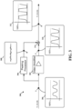
- FIG. 3 is a diagram illustrating an example of a unfocused video signal at various nodes within the processing components 300 of a camera focus assist circuitry.
- contrast slider 218 is set to 100% and the peaking headroom slider 212 is set to 0%. Consequently, the amplitude of the video signal is 100% as depicted in signal block 310 at node C of FIG. 3 .
- the transition edges of the square-wave pattern blend together and produce a pattern as illustrated at node A in signal block 306. This reduction in edge transitions broadens the transition edges, which provides less high frequency components (e.g., Fourier series).
- Peaking processor 304 may receive the unfocused video image signal and provide the peaking signal to signal combiner 314. In particular, peaking processor 304 filters out the low frequency components to provide the peaking signal (e.g., high frequency components) to signal combiner 314. Signal block 308 of the video signal at node B depicts the video signal after peaking processor filters the input signal to the peaking signal. The peaks of peaking signal have lower amplitude because the blurred image does not provide as many high frequency components as a focused video signal.
- Video amplifier 302 may amplify the unfocused video image signal and provide the amplified signal to signal combiner 314.
- Signal block 310 of the video signal at node C depicts the amplified video signal after video amplifier 302 amplifies the input signal. As such, the video signal of signal block 310 has been amplified from the video signal of signal block 306.
- Signal combiner 314 combines the peaking signal from peaking processor 304 with the amplified signal from video amplifier 302. As depicted in signal block 312 at node D, the peaks of the peaking signal add to the amplified signal. In this instance, the broadening effect of the video signal caused by the lens being unfocused does not produce high amplitude peaks in the output video signal. As depicted, the broadened peaking signal do not exceed 100% luminance and therefore does not distort (e.g., clip) the output video signal.
- a camera captures a focused video image signal of horizontal square-wave pattern (e.g., steep transition edges).
- the camera includes focus assist circuitry, however, the peaking headroom is disabled (e.g., 0% peaking headroom) similar to the settings depicted in viewfinder 100 of FIG. 1A .
- the video signal is focused on the square-wave pattern as indicated by sharp definitive transition edge transitions.
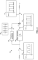
- FIG. 4 is a diagram illustrating an example of signals at various nodes within the hardware components of a camera focus assist circuitry with peaking headroom disabled for a focused video signal.
- contrast slider 218 is set to 100% and the peaking headroom slider 212 is set to 0%. Consequently, the amplitude of the video signal is 100% as depicted in signal block 410 at node C of FIG. 4 .
- the transition edges of the square-wave pattern are steep (e.g., sharp) and produce a pattern as illustrated at node A in signal block 406.
- the steep transition edges include more high frequency components (e.g., Fourier series) than the unfocused video signal ( FIG. 3 at signal block 306).
- Peaking processor 404 may receive the focused video image signal and provides the peaking signal to signal combiner 414. Peaking processor 404 filters out the low frequency components to provide the peaking signal (e.g., high frequency components) to signal combiner 414. Signal block 408 at node B depicts the video signal after peaking processor filters the input signal to the peaking signal. In this instance, the peaks of peaking signal are spikes with high amplitude that correspond to the high frequency components of the edge transitions.
- Video amplifier 402 may amplify the focused video image signal and provide the amplified signal to signal combiner 414.
- Signal block 410 at node C depicts the amplified video signal after video amplifier 402 amplifies the input signal. As such, the video signal of signal block 410 has been amplified from the video signal of signal block 406.
- Signal combiner 414 is configured to combine the peaking signal from peaking processor 404 with the amplified signal from video amplifier 402. As depicted in signal block 412 at node D, the peaks of the peaking signal of node B add to the amplified signal of node C. In this instance, the spikes in the peaking signal produce high amplitude peaks in the output video signal and peaks that exceed 100% luminance and are clipped, which distorts (e.g., clips) output video signal for the viewfinder. This means that the distorted video signal peaks (e.g., clipped peaks) may become indistinguishable from non-peaks of the video signal as the viewfinder processes and renders the video signal into viewable pixels as illustrated in viewfinder 100 of FIG. 1A .
- a camera captures a focused video image signal of horizontal square-wave pattern (e.g., steep transition edges).
- the camera includes focus assist circuitry with the peaking headroom set to 50% similar to the settings depicted in viewfinder 100 of FIG. 1B .
- the video signal is focused on the square-wave pattern as indicated by sharp definitive transition edge transitions.
- FIG. 5 is a diagram illustrating an example of signals at various nodes within the hardware components of a camera focus assist circuitry with peaking head room set to 50% for a focused video signal.
- the focused video signal causes the transition edges of the square-wave pattern to be steep (e.g., sharp) and produce a pattern as illustrated at node A in signal block 506.
- the steep transition edges include more high frequency components (e.g., Fourier series) than the unfocused video signal ( FIG. 3 at signal block 306).
- Peaking processor 504 may receive the focused video image signal and may provide the peaking signal to signal combiner 514. In particular, peaking processor 504 filters out the low frequency components to provide the peaking signal (e.g., high frequency components) to signal combiner 514.
- Signal block 508 at node B depicts the video signal after peaking processor filters the input signal to the peaking signal. In this instance, the peaks of peaking signal are spikes with a high amplitude that correspond to the high frequency components of the edge transitions.
- Video amplifier 502 may amplify the focused video image signal and provide the amplified signal to signal combiner 514.
- peaking headroom has been enabled and set to 50%, which limits the gain applied to video amplifier 502.
- Signal block 510 at node C depicts the amplified video signal after video amplifier 502 amplifies the input signal with the gain limited to provide 50% headroom for peaks.
- the video signal of signal block 510 has been amplified from the video signal of signal block 506.
- the amplitude of the video signal depicted in signal block 510 has been restricted to provide 50% peaking headroom.
- Signal combiner 514 is configured to combine the peaking signal from peaking processor 504 with the amplified signal from video amplifier 502. As depicted in signal block 512 at node D, the peaks of the peaking signal of node B add to the amplified signal of node C. In this instance, the spikes in the peaking signal produce high amplitude peaks in the output video signal and peaks that may exceed 100% luminance. However, the 50% more headroom has been provide to reduce signal distortions in output video signal. Providing 50% more peaking headroom as depicted in signal block 512 results in less distortion (e.g., clipping) the output video signal than the output video signal depicted in signal block 412 of peaking headroom disabled ( FIG. 4 ).
- output video signal of signal block 512 at node D provides more distinguishable signal peaks than output video signal of signal block 412 at node D ( FIG. 4 ).
- the distinction between output video signal of signal block 512 at node D and the output video signal of signal block 412 at node D ( FIG. 4 ) is clearly distinguishable by comparing the viewing region 102 with 50% peaking headroom ( FIG. 1B ) to the viewing region 102 with 0% peaking headroom ( FIG. 1A ).
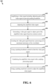
- FIG. 6 is a flowchart of a method of providing peaking headroom for a viewfinder 100.
- the viewfinder 100 may be a flat panel viewfinder such as an LCD, LED, OLED, and the like.
- the viewfinder 100 may include focus assist circuitry configured to provide headroom for peaking signals.
- the focus assist circuitry may include circuitry configured to amplify a video signal including adjusting gain of the video signal to provide peaking headroom.
- the focus assists circuitry may include video amplifier 238, 302, 402, 502 configured to amplify an input video signal from a camera or other video media device.
- the circuitry may limit the gain of video amplifier 238, 302, 402, 502 to provide headroom for peaking signals.
- video gain controller 230 may be configured to limit the gain that video amplifier 238, 302, 402, 502 applies to the amplified signal.
- video gain controller 230 may determine the gain based on user input controls (e.g., peaking headroom control 214 and contrast control 220).
- the focus assist circuitry may include circuitry configured to adjust the amplified video signal.
- the focus assist circuitry may include signal combiner 240 that is configured to combine an amplified video signal with a peaking signal.
- peaking processor 236, 304, 404, 504 may be a high-pass filter configured to filter out low frequency signals from the input video signal for combination with an amplified input signal from video amplifier 238, 302, 402, 502. In such instances, peaking processor 236, 304, 404, 504 combines high frequency peaking components of the input signal with an amplified video signal.
- the video gain controller 230 configured to adjust gain of the video signal may include circuitry to generate a video gain signal for adjusting the gain of the video signal based on contrast control.
- video gain controller 230 may be configured to generate a video gain signal to video amplifier 238 based on user input from contrast control. For example, a user may set contrast to 50% in contrast control 220 and in turn, video gain controller 230 may generate a gain signal for half the gain range (e.g., 50% of max gain determined by maximum gain calculator 228).
- video gain controller 230 may include video gain signal generator 226 that is configured to generate a gain signal for video amplifier 238, 302, 402, 502 based on a contrast value from contrast control 220.
- the video gain controller 230 configured to adjust gain of the video signal may include circuitry to adjust gain of the video signal. In some instances, this may include limiting the video gain signal based on a percentage of a maximum luminance of the viewfinder.
- the focus assist circuitry may be designed for a specific flat panel viewfinder (e.g., LCD, LED, OLED). As such, the focus assist circuitry may implement the maximum luminance of the viewfinder as a parameter for the circuit design. To provide built in headroom for the circuit design a percentage of a maximum luminance of the viewfinder may be set.
- video gain controller 230 may be configured to dynamically limit the generated video gain signal based on a percentage of a maximum luminance of the viewfinder and on control inputs from a user (e.g., peaking headroom control, contrast control).
- maximum gain calculator 228 may take in to account maximum luminance of the viewfinder when providing the video gain signal generator the maximum gain value. Further, in some instances, the video gain signal may be based on a percentage of a maximum luminance of the viewfinder
- the video gain controller 230 configured to adjust gain of the video signal may include circuitry to use a peaking headroom control to limit the video gain signal.
- the video gain controller 230 may be configured to limit the generated video gain signal based on peaking headroom control 214 (e.g., peaking headroom slider 212) of the user interface.
- peaking headroom control 214 may provide a peaking headroom value to maximum gain calculator 228 in order to determine the maximum gain and limit the generated video gain signal independent of contrast.
- the signal combiner 240 configured to adjust gain of the video signal may include circuitry to combine the amplified video signal with a peaking processing signal.
- the focus assist circuitry may include signal combiner 240, 314, 414, 514 to superimpose a pealing signal from peaking processor 236, 304, 404, 504 and an amplified input signal from video amplifier 238, 302, 402, 502.
- the peaking processor 236, 304, 404, 504 may adjust the peaking signal in response to changes in a peaking control signal.
- the adjustments by a user at peaking amplitude control 208 may initiate changes in the peaking control signal.
- the focus assist circuitry may use a peaking amplitude control circuit or module to adjust the amplified video signal.
- peaking amplitude control 208 may be configured to provide a peaking amplitude value to peaking processor 236 in order to adjust the output peaking signal.
- the aspects of the present disclosure are presented with reference to systems and methods used to configure various components of a media production system that may be used for production of television programming or at sports events.
- the various concepts presented throughout this disclosure may be implemented across a broad variety of media production/advertisement systems.
Landscapes
- Engineering & Computer Science (AREA)
- Multimedia (AREA)
- Signal Processing (AREA)
- Human Computer Interaction (AREA)
- Studio Devices (AREA)
- Controls And Circuits For Display Device (AREA)
Description
- The present disclosure relates generally to an apparatus that assists in focusing camera viewfinders particularly, to an apparatus to reducing and limiting the video gain in the viewfinder processing to provide more contrast for focusing techniques such as aperture correction or edge enhancement.
- In high definition (HD) broadcast camera systems, various techniques have been developed for camera viewfinders to help camera operator focus the camera lens. For example, one technique displays a magnified portion of a scene in a viewfinder whereby the camera lens is adjusted to bring the magnified portion into sharp focus. The basis for this technique is that the larger magnified portion provides more detail in the vicinity of the region of interest from which to focus thereby facilitating focusing. Another technique particularly useful for automatic focusing implements specific video processing to enhance contours in a viewfinder to obtain stressed contours when the viewfinder signal is correctly focused.
- The majority of these techniques have been developed for cathode ray tube (CRT) viewfinders that may accommodate peaking signals well above 100% of operating luminosity. As such, these techniques are less effective and may be inadequate for more modern technologies such as liquid crystal displays (LCD) and organic light emitting diodes (OLEDs).
-
JP2010050592 -
US5496106 discloses a system for generating and displaying a contrast false color overlay as a focus assist includes a signal divider, an automatic gain control unit, an adder, a signal reducer and a signal combiner. - The following presents a simplified summary of one or more aspects in order to provide a basic understanding of such aspects. This summary is not an extensive overview of all contemplated aspects, and is intended to neither identify key or critical elements of all aspects nor delineate the scope of any or all aspects. Its sole purpose is to present some concepts of one or more aspects in a simplified form as a prelude to the more detailed description that is presented later.
- An aspect of the invention is a focus assist circuit according to claim 1.
- A further aspect of the invention is a method of providing peaking headroom for a camera viewfinder according to claim 5.
- Additional advantages and novel features of these aspects will be set forth in part in the description that follows, and in part will become more apparent to those skilled in the art upon examination of the following or upon learning by practice of the invention.
- For a better understanding of the various described aspects, reference should be made to the description below, in conjunction with the following figures in which like reference numerals refer to corresponding parts throughout the figures.
-
FIG. 1A illustrates an example of a LCD viewfinder with peaking headroom disabled in the camera focus assist circuitry. -
FIG. 1B illustrates an example of a LCD viewfinder with peaking headroom enabled in the camera focus assist circuitry. -
FIG. 2 is a diagram illustrating an example of the connectivity between GUI, software modules, and hardware components of a camera focus assist circuitry. -
FIG. 3 is a diagram illustrating an example of unfocused video signals at various nodes within the processing components of a camera focus assist circuitry. -
FIG. 4 is a diagram illustrating an example of signals at various nodes within the hardware components of a camera focus assist circuitry with peaking head room disabled for a focused video signal. -
FIG. 5 is a diagram illustrating an example of signals at various nodes within the hardware components of a camerafocus assist apparatus 100 with peaking head room set to 50% for a focused video signal. -
FIG. 6 is a flowchart of a method of providing peaking headroom for a camera viewfinder. - The detailed description set forth below in connection with the appended drawings is intended as a description of various configurations and is not intended to represent the only configurations in which the concepts described herein may be practiced. The detailed description includes specific details for the purpose of providing a thorough understanding of various concepts. However, it will be apparent to those skilled in the art that these concepts may be practiced without these specific details. In some instances, well known structures and components are shown in block diagram form in order to avoid obscuring such concepts.
- Aspects of video production systems will now be presented with reference to various apparatus and methods. These apparatus and methods will be described in the following detailed description and illustrated in the accompanying drawing by various blocks, components, circuits, steps, processes, algorithms, etc. (collectively referred to as "elements"). These elements may be implemented using electronic hardware, computer software, or any combination thereof. Whether such elements are implemented as hardware or software depends upon the particular application and design constraints imposed on the overall system.
- By way of example, an element, or any portion of an element, or any combination of elements may be implemented as a "processing system" that includes one or more processors. Examples of processors include microprocessors, microcontrollers, graphics processing units (GPUs), central processing units (CPUs), application processors, digital signal processors (DSPs), reduced instruction set computing (RISC) processors, systems on a chip (SoC), baseband processors, field programmable gate arrays (FPGAs), programmable logic devices (PLDs), state machines, gated logic, discrete hardware circuits, and other suitable hardware configured to perform the various functionality described throughout this disclosure. One or more processors in the processing system may execute software. Software shall be construed broadly to mean instructions, instruction sets, code, code segments, program code, programs, subprograms, software components, applications, software applications, software packages, routines, subroutines, objects, executables, threads of execution, procedures, functions, etc., whether referred to as software, firmware, middleware, microcode, hardware description language, or otherwise.
- Accordingly, in one or more example embodiments, the functions described may be implemented in hardware, software, or any combination thereof. If implemented in software, the functions may be stored on or encoded as one or more instructions or code on a computer-readable medium. Computer-readable media may include transitory or non-transitory computer storage media for carrying or having computer-executable instructions or data structures stored thereon. Both transitory and non-transitory storage media may be any available media that can be accessed by a computer as part of the processing system. By way of example, and not limitation, such computer-readable media can comprise a random-access memory (RAM), a read-only memory (ROM), an electrically erasable programmable ROM (EEPROM), optical disk storage, magnetic disk storage, other magnetic storage devices, combinations of the aforementioned types of computer-readable media, or any other medium that can be used to store computer executable code in the form of instructions or data structures that can be accessed by a computer. Further, when information is transferred or provided over a network or another communications connection (either hardwired, wireless, or combination thereof) to a computer, the computer or processing system properly determines the connection as a transitory or non-transitory computer-readable medium, depending on the particular medium. Thus, any such connection is properly termed a computer-readable medium. Combinations of the above should also be included within the scope of the computer-readable media. Non-transitory computer-readable media excludes signals per se and the air interface.
- One property of CRT based viewfinders is that they do not distort peaking signals that exceed a 100% luminance of non-peaking signals. As such, CRT viewfinders set at a 100% luminance may illuminate peaking signals with a high luminance than 100%. This means that peaking signals may illuminate brighter than non-peaking signal even when peaking signals are pegged at 100% luminance. Focus assist video processing circuitry (e.g., peaking, contour, sharpness, or aperture) make use of this property in CRT based viewfinders to assist in focusing a lens.
- By comparison, the light emitting mechanisms differ between CRT viewfinders and flat panel displays (FPD) viewfinders. CRT viewfinders are configured to convert an analog video signal into an electron beam that bombards a phosphorescent screen with electrons to produce images. Whereas LCD viewfinders, for example, do not emit light directly and instead rely on a backlight or a reflector to emit images through a liquid crystal. As such, the peaking signals and non-peaking signals of LCD viewfinders may not exceed the maximum luminance of the backlight (e.g., 100% luminance). This means that signals that exceed 100% luminance may be clipped and indistinguishable from other peaking signals that also exceed 100% luminance. This inability to distinguish particular signals makes focusing difficult.
- In addition, the video signal differs between CRT viewfinders and FPD viewfinders. The video signal applied to the CRT is analog and can be overdriven (e.g., luminance greater than 100%) for some time without immediately destroying or wearing out the phosphor. This is a property carefully utilized in CRT viewfinders to distinguish peaking signals that exceed 100% luminance. In contrast, the signal applied to FPDs is digital and cannot overdrive beyond a maximum value (e.g., FFh). For example, applying a digital signal FFh (e.g., 100% luminance) for R,G and B results in a maximum white screen and any signal (e.g., peaking signal) in excess of FFh is interpreted a maximum white screen with a value of FFh.
- Recent improvements in flat panel display technologies have made flat panel viewfinders much more appealing than CRTs. For one, flat panel viewfinders may provide much higher resolution than CRT viewfinders. For another, flat panel viewfinders (e.g., light emitting diode, and OLEDs) tend to have a higher light output with significantly lower power draw than CRTs. Despite the these benefits, flat panel viewfinders are still susceptible to signal distortions such as clipping. As such, focusing flat panel viewfinders is challenging compared to their CRT counterparts.
- One technique to assist in focusing and preventing signal distortion (e.g., clipping) in an output video signal is to implement peaking headroom in focusing assist apparatus circuitry, which restricts the output luminosity to provide headroom in the viewfinders luminance for peaking signals.
-
FIG. 1A illustrates an example of a viewfinder with peaking headroom disabled in the camera focus assist circuitry. Theviewfinder 100 displays theviewing region 102 that shows the image captured by the camera sensors (e.g., CMOS sensor, CCD sensor) and the graphical user interface (GUI) 104. As depicted,viewing region 102 captures an image of a circular disc with concentric interference patterns. Theviewfinder 100 may be a touch screen with GUI controls (e.g., peaking amplitude, peaking headroom, contrast) that may be touch activated by a finger, stylus and the like. TheGUI 104 may include user interface elements such as input controls, navigation components, information components, and containers. As input controls,GUI 104 includes peakingamplitude control 108, peakingheadroom control 114, andcontrast control 120. Further, input controls include peakingamplitude slider 106, peakingheadroom slider 112, andcontrast slider 118 for adjusting the input control. Conceivably, other input controls forGUI 104 may be buttons (e.g., radio buttons, dropdown buttons), selectors (e.g., dropdown lists, checkboxes, list boxes, date and time pickers, etc.), sliders, toggles, and the like. The input controls may also include indicators such as peakingamplitude indicator 110, peakingheadroom indicator 116, andcontrast indicator 122. - It should be appreciated that aspects of
viewfinder 100 and camera focus assist circuitry are not limited to GUI interface. For instance, in some embodiments,viewfinder 100 may be a screen that includes buttons, switches, and other electrical devices (e.g., mouse, trackball) to navigate various menus, input controls, navigation components, information components, and containers. As such, a user interface may include scrolling to various menus displayed on LCD viewfinder using a scroll switch and selecting various menus may be actuated depressing a button. - In reference to the example of
FIG. 1A , peakingheadroom slider 112 is positioned to disable the peaking headroom circuitry as displayed in peakingheadroom indicator 116 of 0%. Consequently, peaking signals of the captured image may be distorted (e.g., clipped) and indistinguishable from non-peaking images displayed in theviewing region 102 ofviewfinder 100. As depicted, the signal peaks from the edge regions of the concentric interference patterns blend in with the background of the circular disc pattern image. -
FIG. 1B illustrates an example of a LCD viewfinder with peaking headroom enabled in the camera focus assist circuitry. In this example, peakingheadroom slider 112 is positioned to 50% peaking headroom as displayed on peakingheadroom indicator 116. This results in less peaking signals of the captured image being clipped, which provides for more distinguishable peaking signals displayed in theviewing region 102 ofviewfinder 100. As depicted, the additional headroom of 50% provides the peaking signals to illuminate without distortion. The signal peaks emphasize the edge regions of the concentric interference patterns in the center region of the captured image alongside the non-peaking signals in the periphery that are darker. By comparison withFIG. 1A , the video image ofFIG. 1B provides more distinguishable features at the edges (e.g., crisp image), which facilitates focusing the camera lens. - In some embodiments, a color may overlay the peaking regions to highlight the peaking region. For example, a fluorescent green or fluorescent yellow may be applied to the region of
FIG. 1A that corresponds to peaking region. This provides a visible distinguishing feature on the display. In some cases, a fluorescent green or fluorescent yellow may overlay the peaking regions that are being clipped byviewfinder 100. -
FIG. 2 is a diagram illustrating an example of the connectivity between GUI, software modules, and hardware components of a camera focus assist circuitry. As depicted,GUI 204 includes peakingamplitude control 208, a peakingamplitude slider 206, a peakingamplitude indicator 210, peakingheadroom control 214, a peakingheadroom slider 212, a peaking headroom indicator 215, andcontrast control 220, acontrast slider 218, and acontrast indicator 222. - As depicted, peaking
amplitude control 208 receives user input and provides a selected peaking amplitude value to peakingprocessor 236.Peaking amplitude control 208 may be the means for controlling peaking amplitude. For example, a user may adjust peakingamplitude slider 206 to select a peaking amplitude value of 50% to be applied to peakingprocessor 236. In some embodiments, peakingprocessor 236 is a software module that output a peaking signal from thevideo input 242. -
Peaking headroom control 214 may receive input from a user and provide a selected peaking headroom value tomaximum gain calculator 228. The peakingheadroom control 214 provides means for controlling peaking headroom. That is, a user may adjust peakingheadroom slider 212 to select a peaking headroom value of 50% to be provided tomaximum gain calculator 228. In turn,maximum gain calculator 228 may calculate the maximum gain that videogain signal generator 226 may apply based on the peaking headroom value. For example, in some instances a circuit may only support a maximum gain (e.g., 10 out of 10) before distortions (e.g., clipping) occurs in a LCD viewfinder. In such an example,maximum gain calculator 228 may determine that maximum gain (e.g., 5 out of 10) may be applied for a peaking headroom value of 50%. -
Video gain controller 230 may include videogain signal generator 226 andmaximum gain calculator 228. The videogain signal generator 226 may be a hardware or software module with means for limiting the video gain signal such as limiting a range for the video gain signal. In addition, the videogain signal generator 226 may limit the gain range based on the maximum gain determined bymaximum gain calculator 228. For example,maximum gain calculator 228 may set the maximum gain value (e.g., gain of 5 out of 10 for peaking headroom of 50%) for videogain signal generator 226. In such an example, videogain signal generator 226 may not exceed gain of 50% (e.g., gain of 5 out of 10), which corresponds to contrast of 100% (e.g., full contrast). -
Maximum gain calculator 228 may be a hardware of software module such as a programmable firmware encoded on a programmable electronic device. In some embodiments, for example,maximum gain calculator 228 is a hardware module configured to receive a peaking heading value from peakingheadroom control 214 and provide a maximum gain setting for videogain signal generator 226. Peakingheadroom slider 212 may adjust the gain formaximum gain calculator 228, which may be circuitry (e.g., resistance limiter, current limiter, voltage limiter) configured to limit the maximum gain thatvideo gain controller 230 may apply tovideo amplifier 238. -
Contrast control 220 may receive input from a user and provides a selected contrast value to videogain signal generator 226. In particular, a user may adjust the position ofcontrast slider 218 to select a contrast value of 100% to be provided to videogain signal generator 226. As depicted inFIG. 2 , for example,contrast slider 218 may set a contrast to 100% for videogain signal generator 226, which adjusts the gain signal to half the maximum gain value provided by maximum gain calculator 228 (e.g., based onmaximum gain calculator 228 set at 50%). - As depicted in
FIG. 2 ,video gain controller 230 may includemaximum gain calculator 228 that provides a maximum gain value to videogain signal generator 226. In particular, peakingheadroom control 214 may provide peaking headroom value tomaximum gain calculator 228, which in turn determines the maximum gain based on the peaking headroom value and maximum the luminance of the viewfinder. For example, a peaking headroom value of 50% provides a maximum gain value of half the maximum the luminance of the viewfinder to videogain signal generator 226. - Further, the
video gain controller 230 and/or the videogain signal generator 226 may provide the means for adjusting gain of the amplifying means to provide peaking headroom. That is, for example, a user may adjust the peakingheadroom slider 212, which causesmaximum gain calculator 228 to change the maximum gain value. Further, the videogain signal generator 226 adjusts the gain signal based on the maximum gain value. In some embodiments, thevideo gain controller 230 may be the means for limiting the video gain signal and may be configured to usemaximum gain calculator 228 to limit the video gain signal based on the peakingheadroom control 214. It should be appreciated that adjusting thecontrast slider 218 may also causes the videogain signal generator 226 to adjust the gain signal. - In some embodiments,
video gain controller 230 is a software module. For example,video gain controller 230 is set of instructions encoded on programmable firmware of an electronic device. In other embodiments,video gain controller 230 is a hardware module configured to receive a contrast value fromcontrast control 220 and provide a maximum gain setting forvideo gain controller 230. In some embodiments,video gain controller 230 is the means for adjusting gain and may include videogain signal generator 226 as the means for generating a video gain signal. Further, the videogain signal generator 226 may use the video gain signal for adjusting the gain of the means based on user input fromcontrast control 220. -
Peaking processor 236 may receive input fromvideo input 242 and peaking amplitude value from peakingamplitude control 208 and outputs a peaking signal to signalcombiner 240. In some embodiments, peakingprocessor 236 is a high-pass filter configured to filter out low frequency signals from the input video signal to signalcombiner 240 for combination with an amplified input signal fromvideo amplifier 238. In some embodiments, peakingprocessor 236 is a transversal filter configured to increase the steepness of amplitude transitions of video signals. In such a transversal filter, a desired amplitude or phase characteristic (or both) as a function of frequency may be formed substantially without introducing phase non-linearity or phase distortion.Peaking amplitude control 208 may input a peaking amplitude value in peakingprocessor 236 to adjust the filter based on user input control from peakingamplitude control 208. -
Video amplifier 238 may receive input fromvideo input 242 andvideo gain controller 230 and outputs an amplified signal to signalcombiner 240. That is,video amplifier 238 may provide the amplification means for amplifying a video signal. In some embodiments,video amplifier 238 is configured to amplify a video signal fromvideo input 242 based on a gain value from videogain signal generator 226 ofvideo gain controller 230. In some cases, the videogain signal generator 226 may adjust the video gain applied tovideo amplifier 238 based on user inputs from peakingheadroom control 214 andcontrast control 220. The amplified output video signal ofvideo amplifier 238 feeds intosignal combiner 240. -
Signal combiner 240 may receive input from peakingprocessor 236 andvideo amplifier 238.Signal combiner 240 may be a module or circuit that is configured to with the means for adjusting the amplified video signal. That is,signal combiner 240 is the means for combining the amplified video signal with a peaking processing signal. In some embodiments,signal combiner 240 is configured to receive the amplified video signal fromvideo amplifier 238. In turn,signal combiner 240 outputs a superposition of the video signal from peakingprocessor 236 andvideo amplifier 238. - It should be appreciated that the configuration to combine a video peaking signal and an amplified video signal is not limited to a viewfinder. For example, peaking processing may be implemented in a camera. In addition, it should be appreciated that the mechanisms to implement peaking headroom may vary.
- In another approach, peaking headroom may be applied by reducing and limiting the video gain in the viewfinder processing. That is, in an 8 bit viewfinder display system the 256 luminance levels may be compressed to 128 luminance levels by the
video gain controller 230. As such, the remaining levels may be reserved as headroom for the peaking signals that are added to the video signal aftercontrast control 220. - In this example, a camera captures an unfocused video image signal of horizontal square-wave pattern (e.g., steep transition edges). The video signal is unfocused on the square-wave patter, which causes the transition edges blend together and produce a blurred pattern without sharp definitive edge transitions.
-
FIG. 3 is a diagram illustrating an example of a unfocused video signal at various nodes within theprocessing components 300 of a camera focus assist circuitry. In this instance,contrast slider 218 is set to 100% and the peakingheadroom slider 212 is set to 0%. Consequently, the amplitude of the video signal is 100% as depicted insignal block 310 at node C ofFIG. 3 . Because the image is unfocused, the transition edges of the square-wave pattern blend together and produce a pattern as illustrated at node A insignal block 306. This reduction in edge transitions broadens the transition edges, which provides less high frequency components (e.g., Fourier series). -
Peaking processor 304 may receive the unfocused video image signal and provide the peaking signal to signalcombiner 314. In particular, peakingprocessor 304 filters out the low frequency components to provide the peaking signal (e.g., high frequency components) to signalcombiner 314.Signal block 308 of the video signal at node B depicts the video signal after peaking processor filters the input signal to the peaking signal. The peaks of peaking signal have lower amplitude because the blurred image does not provide as many high frequency components as a focused video signal. -
Video amplifier 302 may amplify the unfocused video image signal and provide the amplified signal to signalcombiner 314.Signal block 310 of the video signal at node C depicts the amplified video signal aftervideo amplifier 302 amplifies the input signal. As such, the video signal ofsignal block 310 has been amplified from the video signal ofsignal block 306. -
Signal combiner 314 combines the peaking signal from peakingprocessor 304 with the amplified signal fromvideo amplifier 302. As depicted insignal block 312 at node D, the peaks of the peaking signal add to the amplified signal. In this instance, the broadening effect of the video signal caused by the lens being unfocused does not produce high amplitude peaks in the output video signal. As depicted, the broadened peaking signal do not exceed 100% luminance and therefore does not distort (e.g., clip) the output video signal. - In this example, a camera captures a focused video image signal of horizontal square-wave pattern (e.g., steep transition edges). The camera includes focus assist circuitry, however, the peaking headroom is disabled (e.g., 0% peaking headroom) similar to the settings depicted in
viewfinder 100 ofFIG. 1A . The video signal is focused on the square-wave pattern as indicated by sharp definitive transition edge transitions. -
FIG. 4 is a diagram illustrating an example of signals at various nodes within the hardware components of a camera focus assist circuitry with peaking headroom disabled for a focused video signal. In this instance,contrast slider 218 is set to 100% and the peakingheadroom slider 212 is set to 0%. Consequently, the amplitude of the video signal is 100% as depicted insignal block 410 at node C ofFIG. 4 . Because the video signal is focused the transition edges of the square-wave pattern are steep (e.g., sharp) and produce a pattern as illustrated at node A insignal block 406. The steep transition edges include more high frequency components (e.g., Fourier series) than the unfocused video signal (FIG. 3 at signal block 306). -
Peaking processor 404 may receive the focused video image signal and provides the peaking signal to signalcombiner 414.Peaking processor 404 filters out the low frequency components to provide the peaking signal (e.g., high frequency components) to signalcombiner 414.Signal block 408 at node B depicts the video signal after peaking processor filters the input signal to the peaking signal. In this instance, the peaks of peaking signal are spikes with high amplitude that correspond to the high frequency components of the edge transitions. -
Video amplifier 402 may amplify the focused video image signal and provide the amplified signal to signalcombiner 414.Signal block 410 at node C depicts the amplified video signal aftervideo amplifier 402 amplifies the input signal. As such, the video signal ofsignal block 410 has been amplified from the video signal ofsignal block 406. -
Signal combiner 414 is configured to combine the peaking signal from peakingprocessor 404 with the amplified signal fromvideo amplifier 402. As depicted insignal block 412 at node D, the peaks of the peaking signal of node B add to the amplified signal of node C. In this instance, the spikes in the peaking signal produce high amplitude peaks in the output video signal and peaks that exceed 100% luminance and are clipped, which distorts (e.g., clips) output video signal for the viewfinder. This means that the distorted video signal peaks (e.g., clipped peaks) may become indistinguishable from non-peaks of the video signal as the viewfinder processes and renders the video signal into viewable pixels as illustrated inviewfinder 100 ofFIG. 1A . - In this example, a camera captures a focused video image signal of horizontal square-wave pattern (e.g., steep transition edges). The camera includes focus assist circuitry with the peaking headroom set to 50% similar to the settings depicted in
viewfinder 100 ofFIG. 1B . The video signal is focused on the square-wave pattern as indicated by sharp definitive transition edge transitions. -
FIG. 5 is a diagram illustrating an example of signals at various nodes within the hardware components of a camera focus assist circuitry with peaking head room set to 50% for a focused video signal. In this instance, the focused video signal causes the transition edges of the square-wave pattern to be steep (e.g., sharp) and produce a pattern as illustrated at node A insignal block 506. The steep transition edges include more high frequency components (e.g., Fourier series) than the unfocused video signal (FIG. 3 at signal block 306). -
Peaking processor 504 may receive the focused video image signal and may provide the peaking signal to signalcombiner 514. In particular, peakingprocessor 504 filters out the low frequency components to provide the peaking signal (e.g., high frequency components) to signalcombiner 514.Signal block 508 at node B depicts the video signal after peaking processor filters the input signal to the peaking signal. In this instance, the peaks of peaking signal are spikes with a high amplitude that correspond to the high frequency components of the edge transitions. -
Video amplifier 502 may amplify the focused video image signal and provide the amplified signal to signalcombiner 514. In this instance peaking headroom has been enabled and set to 50%, which limits the gain applied tovideo amplifier 502.Signal block 510 at node C depicts the amplified video signal aftervideo amplifier 502 amplifies the input signal with the gain limited to provide 50% headroom for peaks. As such, the video signal ofsignal block 510 has been amplified from the video signal ofsignal block 506. By comparison withsignal block 410 ofFIG. 4 , the amplitude of the video signal depicted insignal block 510 has been restricted to provide 50% peaking headroom. -
Signal combiner 514 is configured to combine the peaking signal from peakingprocessor 504 with the amplified signal fromvideo amplifier 502. As depicted insignal block 512 at node D, the peaks of the peaking signal of node B add to the amplified signal of node C. In this instance, the spikes in the peaking signal produce high amplitude peaks in the output video signal and peaks that may exceed 100% luminance. However, the 50% more headroom has been provide to reduce signal distortions in output video signal. Providing 50% more peaking headroom as depicted insignal block 512 results in less distortion (e.g., clipping) the output video signal than the output video signal depicted insignal block 412 of peaking headroom disabled (FIG. 4 ). As such, output video signal ofsignal block 512 at node D provides more distinguishable signal peaks than output video signal ofsignal block 412 at node D (FIG. 4 ). The distinction between output video signal ofsignal block 512 at node D and the output video signal ofsignal block 412 at node D (FIG. 4 ) is clearly distinguishable by comparing theviewing region 102 with 50% peaking headroom (FIG. 1B ) to theviewing region 102 with 0% peaking headroom (FIG. 1A ). -
FIG. 6 is a flowchart of a method of providing peaking headroom for aviewfinder 100. Theviewfinder 100 may be a flat panel viewfinder such as an LCD, LED, OLED, and the like. Theviewfinder 100 may include focus assist circuitry configured to provide headroom for peaking signals. - In one embodiment, at
block 602, the focus assist circuitry may include circuitry configured to amplify a video signal including adjusting gain of the video signal to provide peaking headroom. In particular, the focus assists circuitry may includevideo amplifier video amplifier video gain controller 230 may be configured to limit the gain thatvideo amplifier video gain controller 230 may determine the gain based on user input controls (e.g., peakingheadroom control 214 and contrast control 220). - In one embodiment, at
block 604, the focus assist circuitry may include circuitry configured to adjust the amplified video signal. For example, the focus assist circuitry may includesignal combiner 240 that is configured to combine an amplified video signal with a peaking signal. In some instances, peakingprocessor video amplifier processor - In one embodiment, at
block 606, thevideo gain controller 230 configured to adjust gain of the video signal may include circuitry to generate a video gain signal for adjusting the gain of the video signal based on contrast control. As discussed above with respect toFIG. 2 ,video gain controller 230 may be configured to generate a video gain signal tovideo amplifier 238 based on user input from contrast control. For example, a user may set contrast to 50% incontrast control 220 and in turn,video gain controller 230 may generate a gain signal for half the gain range (e.g., 50% of max gain determined by maximum gain calculator 228). In some embodiments,video gain controller 230 may include videogain signal generator 226 that is configured to generate a gain signal forvideo amplifier contrast control 220. - In one embodiment, at
block 608, thevideo gain controller 230 configured to adjust gain of the video signal may include circuitry to adjust gain of the video signal. In some instances, this may include limiting the video gain signal based on a percentage of a maximum luminance of the viewfinder. For example, the focus assist circuitry may be designed for a specific flat panel viewfinder (e.g., LCD, LED, OLED). As such, the focus assist circuitry may implement the maximum luminance of the viewfinder as a parameter for the circuit design. To provide built in headroom for the circuit design a percentage of a maximum luminance of the viewfinder may be set. Further,video gain controller 230 may be configured to dynamically limit the generated video gain signal based on a percentage of a maximum luminance of the viewfinder and on control inputs from a user (e.g., peaking headroom control, contrast control). - In some instances,
maximum gain calculator 228 may take in to account maximum luminance of the viewfinder when providing the video gain signal generator the maximum gain value. Further, in some instances, the video gain signal may be based on a percentage of a maximum luminance of the viewfinder - In one embodiment, at
block 610, thevideo gain controller 230 configured to adjust gain of the video signal may include circuitry to use a peaking headroom control to limit the video gain signal. For example, thevideo gain controller 230 may be configured to limit the generated video gain signal based on peaking headroom control 214 (e.g., peaking headroom slider 212) of the user interface. In reference toFIG. 2 , in some instances, peakingheadroom control 214 may provide a peaking headroom value tomaximum gain calculator 228 in order to determine the maximum gain and limit the generated video gain signal independent of contrast. - In one embodiment, at
block 612, thesignal combiner 240 configured to adjust gain of the video signal may include circuitry to combine the amplified video signal with a peaking processing signal. For example, the focus assist circuitry may includesignal combiner processor video amplifier processor amplitude control 208, for example, may initiate changes in the peaking control signal. - In one embodiment, at
block 614, the focus assist circuitry may use a peaking amplitude control circuit or module to adjust the amplified video signal. For example, as discussed above with respect toFIG. 2 , peakingamplitude control 208 may be configured to provide a peaking amplitude value to peakingprocessor 236 in order to adjust the output peaking signal. - By way of example and without limitation, the aspects of the present disclosure are presented with reference to systems and methods used to configure various components of a media production system that may be used for production of television programming or at sports events. The various concepts presented throughout this disclosure may be implemented across a broad variety of media production/advertisement systems.
- It is understood that the specific order or hierarchy of blocks in the processes / flowcharts disclosed is an illustration of example approaches. Based upon design preferences, it is understood that the specific order or hierarchy of blocks in the processes / flowcharts may be rearranged. Further, some blocks may be combined or omitted. The accompanying method claims present elements of the various blocks in a sample order, and are not meant to be limited to the specific order or hierarchy presented.
- The previous description is provided to enable any person skilled in the art to practice the various aspects described herein. The invention is defined by the appended claims.
Claims (8)
- A focus assist circuit for a camera viewfinder having an LCD, LED or OLED flat panel display, the focus assist circuit comprising:a video amplifier (238, 302, 402, 502) configured to amplify a video signal;a video gain controller (230) configured to adjust a gain of the video amplifier (238, 302, 402, 502) to provide peaking headroom;a user interface including a contrast control and a peaking headroom control; anda peaking processor (236, 304, 404, 504) configured to adjust the amplified video signal to generate an output signal with distinguishing illuminated signal peaks when the output signal is emitted based on the LCD, the LED or the OLED flat panel display,wherein the video gain controller (230) comprises a video gain signal generator (226) configured to generate a video gain signal for adjusting the gain of the video amplifier (238, 302, 402, 502) based on a value of the contrast control selected by the user interface, andwherein the video gain controller (230) further comprises a video gain limiter configured to limit the video gain signal based on a percentage of a maximum luminance of the camera viewfinder and based on the peaking headroom control selected by the user interface.
- The circuit of claim 1, further comprising a signal combiner configured to receive the amplified video signal from the video amplifier (238, 302, 402, 502), and wherein the peaking processor (236, 304, 404, 504) is further configured to adjust the amplified video signal through the signal combiner.
- The circuit of claim 1, wherein the user interface further includes a peaking amplitude control, and wherein the peaking processor (236, 304, 404, 504) is further configured to adjust the amplified video signal from the video amplifier (238, 302, 402, 502) based on the peaking amplitude control.
- The focus assist circuit of claim 1, wherein the adjusted and amplified video signal is output to be displayed on the LCD, LED or OLED flat panel display of the camera viewfinder without distortion.
- A method of providing peaking headroom for a camera viewfinder having an LCD, LED or OLED flat panel display, comprising:amplifying a video signal including adjusting gain of the video signal to provide peaking headroom; andadjusting the amplified video signal to generate an output signal with distinguishing illuminated signal peaks when the output signal is emitted based on the LCD, the LED or the OLED flat panel display,wherein adjusting the gain of the video signal comprises generating a video gain signal for adjusting the gain of the video signal based on a contrast control value selected by a user interface, andwherein adjusting the gain of the video signal further comprises limiting the video gain signal based on a percentage of a maximum luminance of the camera viewfinder and based on a peaking headroom control.
- The method of claim 5, wherein the adjusting of the amplified video signal comprises combining the amplified video signal with a peaking processing signal.
- The method of claim 5, wherein the adjusting of the amplified video signal comprises using a peaking amplitude control to adjust the amplified video signal.
- The method of claim 5, further comprising displaying the adjusted and amplified video signal on the LCD, LED or OLED flat panel display of the camera viewfinder without distortion.
Applications Claiming Priority (2)
| Application Number | Priority Date | Filing Date | Title |
|---|---|---|---|
| US15/154,893 US10003733B2 (en) | 2016-05-13 | 2016-05-13 | Peaking headroom for flat panel displays |
| PCT/EP2016/082573 WO2017194180A1 (en) | 2016-05-13 | 2016-12-23 | Peaking headroom for flat panel displays |
Publications (2)
| Publication Number | Publication Date |
|---|---|
| EP3456038A1 EP3456038A1 (en) | 2019-03-20 |
| EP3456038B1 true EP3456038B1 (en) | 2023-05-03 |
Family
ID=57821922
Family Applications (1)
| Application Number | Title | Priority Date | Filing Date |
|---|---|---|---|
| EP16826737.5A Active EP3456038B1 (en) | 2016-05-13 | 2016-12-23 | Peaking headroom for flat panel displays |
Country Status (4)
| Country | Link |
|---|---|
| US (2) | US10003733B2 (en) |
| EP (1) | EP3456038B1 (en) |
| CA (1) | CA3023774A1 (en) |
| WO (1) | WO2017194180A1 (en) |
Family Cites Families (15)
| Publication number | Priority date | Publication date | Assignee | Title |
|---|---|---|---|---|
| US3742376A (en) * | 1970-05-15 | 1973-06-26 | Rca Corp | Video amplifiers |
| KR920007607B1 (en) * | 1989-09-01 | 1992-09-08 | 삼성전자 주식회사 | Contrast Adjustment Circuit in Digital Television Receivers |
| DE4015446C2 (en) | 1990-05-14 | 1994-01-05 | Broadcast Television Syst | Television camera |
| DE4018492C2 (en) | 1990-06-09 | 1999-02-04 | Philips Broadcast Television S | Television camera |
| US5496106A (en) * | 1994-12-13 | 1996-03-05 | Apple Computer, Inc. | System and method for generating a contrast overlay as a focus assist for an imaging device |
| WO1999011057A2 (en) | 1997-08-21 | 1999-03-04 | Koninklijke Philips Electronics N.V. | Viewfinder aperture correction |
| JP2001238127A (en) * | 2000-02-21 | 2001-08-31 | Fuji Photo Film Co Ltd | Camera |
| JP4141800B2 (en) * | 2002-11-01 | 2008-08-27 | 株式会社リコー | Digital camera |
| JP4245019B2 (en) * | 2006-09-04 | 2009-03-25 | ソニー株式会社 | Viewfinder, imaging device, and display signal generation circuit |
| JP4508256B2 (en) * | 2008-03-19 | 2010-07-21 | ソニー株式会社 | Video signal processing apparatus, imaging apparatus, and video signal processing method |
| JP2010050592A (en) * | 2008-08-20 | 2010-03-04 | Canon Inc | Image display unit, imaging apparatus, and display method |
| US8421897B2 (en) * | 2009-04-08 | 2013-04-16 | Canon Kabushiki Kaisha | Image capturing apparatus and control method therefor |
| JP2011091602A (en) * | 2009-10-22 | 2011-05-06 | Canon Inc | Image display device, imaging apparatus and method for displaying image |
| JP6172428B2 (en) * | 2012-06-15 | 2017-08-02 | 株式会社リコー | Imaging apparatus and imaging method |
| JP5995637B2 (en) * | 2012-10-04 | 2016-09-21 | キヤノン株式会社 | IMAGING DEVICE, IMAGING DEVICE CONTROL METHOD, PROGRAM, AND STORAGE MEDIUM |
-
2016
- 2016-05-13 US US15/154,893 patent/US10003733B2/en active Active
- 2016-12-23 WO PCT/EP2016/082573 patent/WO2017194180A1/en not_active Ceased
- 2016-12-23 EP EP16826737.5A patent/EP3456038B1/en active Active
- 2016-12-23 CA CA3023774A patent/CA3023774A1/en active Pending
-
2018
- 2018-05-21 US US15/984,726 patent/US10721389B2/en active Active
Also Published As
| Publication number | Publication date |
|---|---|
| EP3456038A1 (en) | 2019-03-20 |
| CA3023774A1 (en) | 2017-11-16 |
| US20170332002A1 (en) | 2017-11-16 |
| US20180278833A1 (en) | 2018-09-27 |
| US10003733B2 (en) | 2018-06-19 |
| US10721389B2 (en) | 2020-07-21 |
| WO2017194180A1 (en) | 2017-11-16 |
Similar Documents
| Publication | Publication Date | Title |
|---|---|---|
| JP5072087B2 (en) | Liquid crystal display device and liquid crystal display method | |
| KR102379601B1 (en) | Method and apparatus for controling video data | |
| US8937631B2 (en) | Image processing circuit and image display apparatus | |
| JP6758891B2 (en) | Image display device and image display method | |
| US9501979B2 (en) | Image display apparatus and control method thereof | |
| US11107439B2 (en) | Image processing apparatus, method of controlling image processing apparatus, and storage medium | |
| JP2006033656A (en) | User interface providing device | |
| KR102349384B1 (en) | Transparent display apparatus, method for controlling the same and computer-readable recording medium | |
| JP2017227775A (en) | Display device and control method thereof | |
| JP2017182702A (en) | Image processing apparatus, control method thereof, and program | |
| US8654257B2 (en) | Image processing apparatus, projector, image processing method, and method for controlling image processing apparatus | |
| US10721389B2 (en) | Peaking headroom for flat panel displays | |
| US10741131B2 (en) | Display apparatus and display method | |
| JP2019053208A (en) | Display device and control method thereof | |
| JPWO2005122558A1 (en) | Image quality control device, method thereof, image quality processing device, program thereof, and recording medium recording the program | |
| US20020051089A1 (en) | Image display apparatus | |
| JP2011158499A (en) | Display control device, display system and display control method | |
| JP2018026606A (en) | Image processing device | |
| JP5901769B2 (en) | Video display device | |
| US20190114994A1 (en) | Image processing apparatus, image processing method, and non-transitory computer readable medium | |
| US9736417B2 (en) | Control system | |
| JP2011158498A (en) | Display control device, display system and display control method | |
| JP2009300886A (en) | Video display device | |
| JP2018056611A (en) | Image processing device and control method thereof | |
| JP2006287636A (en) | Image quality adjustment apparatus, image quality adjustment method, and display apparatus |
Legal Events
| Date | Code | Title | Description |
|---|---|---|---|
| STAA | Information on the status of an ep patent application or granted ep patent |
Free format text: STATUS: UNKNOWN |
|
| STAA | Information on the status of an ep patent application or granted ep patent |
Free format text: STATUS: THE INTERNATIONAL PUBLICATION HAS BEEN MADE |
|
| PUAI | Public reference made under article 153(3) epc to a published international application that has entered the european phase |
Free format text: ORIGINAL CODE: 0009012 |
|
| STAA | Information on the status of an ep patent application or granted ep patent |
Free format text: STATUS: REQUEST FOR EXAMINATION WAS MADE |
|
| 17P | Request for examination filed |
Effective date: 20181109 |
|
| AK | Designated contracting states |
Kind code of ref document: A1 Designated state(s): AL AT BE BG CH CY CZ DE DK EE ES FI FR GB GR HR HU IE IS IT LI LT LU LV MC MK MT NL NO PL PT RO RS SE SI SK SM TR |
|
| AX | Request for extension of the european patent |
Extension state: BA ME |
|
| DAV | Request for validation of the european patent (deleted) | ||
| DAX | Request for extension of the european patent (deleted) | ||
| STAA | Information on the status of an ep patent application or granted ep patent |
Free format text: STATUS: EXAMINATION IS IN PROGRESS |
|
| 17Q | First examination report despatched |
Effective date: 20191204 |
|
| GRAP | Despatch of communication of intention to grant a patent |
Free format text: ORIGINAL CODE: EPIDOSNIGR1 |
|
| STAA | Information on the status of an ep patent application or granted ep patent |
Free format text: STATUS: GRANT OF PATENT IS INTENDED |
|
| INTG | Intention to grant announced |
Effective date: 20220810 |
|
| RAP1 | Party data changed (applicant data changed or rights of an application transferred) |
Owner name: GRASS VALLEY CANADA |
|
| GRAS | Grant fee paid |
Free format text: ORIGINAL CODE: EPIDOSNIGR3 |
|
| GRAA | (expected) grant |
Free format text: ORIGINAL CODE: 0009210 |
|
| STAA | Information on the status of an ep patent application or granted ep patent |
Free format text: STATUS: THE PATENT HAS BEEN GRANTED |
|
| AK | Designated contracting states |
Kind code of ref document: B1 Designated state(s): AL AT BE BG CH CY CZ DE DK EE ES FI FR GB GR HR HU IE IS IT LI LT LU LV MC MK MT NL NO PL PT RO RS SE SI SK SM TR |
|
| REG | Reference to a national code |
Ref country code: GB Ref legal event code: FG4D |
|
| REG | Reference to a national code |
Ref country code: DE Ref legal event code: R096 Ref document number: 602016079217 Country of ref document: DE |
|
| REG | Reference to a national code |
Ref country code: AT Ref legal event code: REF Ref document number: 1565654 Country of ref document: AT Kind code of ref document: T Effective date: 20230515 Ref country code: CH Ref legal event code: EP |
|
| REG | Reference to a national code |
Ref country code: IE Ref legal event code: FG4D |
|
| REG | Reference to a national code |
Ref country code: LT Ref legal event code: MG9D |
|
| REG | Reference to a national code |
Ref country code: NL Ref legal event code: MP Effective date: 20230503 |
|
| REG | Reference to a national code |
Ref country code: AT Ref legal event code: MK05 Ref document number: 1565654 Country of ref document: AT Kind code of ref document: T Effective date: 20230503 |
|
| PG25 | Lapsed in a contracting state [announced via postgrant information from national office to epo] |
Ref country code: SE Free format text: LAPSE BECAUSE OF FAILURE TO SUBMIT A TRANSLATION OF THE DESCRIPTION OR TO PAY THE FEE WITHIN THE PRESCRIBED TIME-LIMIT Effective date: 20230503 Ref country code: PT Free format text: LAPSE BECAUSE OF FAILURE TO SUBMIT A TRANSLATION OF THE DESCRIPTION OR TO PAY THE FEE WITHIN THE PRESCRIBED TIME-LIMIT Effective date: 20230904 Ref country code: NO Free format text: LAPSE BECAUSE OF FAILURE TO SUBMIT A TRANSLATION OF THE DESCRIPTION OR TO PAY THE FEE WITHIN THE PRESCRIBED TIME-LIMIT Effective date: 20230803 Ref country code: NL Free format text: LAPSE BECAUSE OF FAILURE TO SUBMIT A TRANSLATION OF THE DESCRIPTION OR TO PAY THE FEE WITHIN THE PRESCRIBED TIME-LIMIT Effective date: 20230503 Ref country code: ES Free format text: LAPSE BECAUSE OF FAILURE TO SUBMIT A TRANSLATION OF THE DESCRIPTION OR TO PAY THE FEE WITHIN THE PRESCRIBED TIME-LIMIT Effective date: 20230503 Ref country code: AT Free format text: LAPSE BECAUSE OF FAILURE TO SUBMIT A TRANSLATION OF THE DESCRIPTION OR TO PAY THE FEE WITHIN THE PRESCRIBED TIME-LIMIT Effective date: 20230503 |
|
| PG25 | Lapsed in a contracting state [announced via postgrant information from national office to epo] |
Ref country code: RS Free format text: LAPSE BECAUSE OF FAILURE TO SUBMIT A TRANSLATION OF THE DESCRIPTION OR TO PAY THE FEE WITHIN THE PRESCRIBED TIME-LIMIT Effective date: 20230503 Ref country code: PL Free format text: LAPSE BECAUSE OF FAILURE TO SUBMIT A TRANSLATION OF THE DESCRIPTION OR TO PAY THE FEE WITHIN THE PRESCRIBED TIME-LIMIT Effective date: 20230503 Ref country code: LV Free format text: LAPSE BECAUSE OF FAILURE TO SUBMIT A TRANSLATION OF THE DESCRIPTION OR TO PAY THE FEE WITHIN THE PRESCRIBED TIME-LIMIT Effective date: 20230503 Ref country code: LT Free format text: LAPSE BECAUSE OF FAILURE TO SUBMIT A TRANSLATION OF THE DESCRIPTION OR TO PAY THE FEE WITHIN THE PRESCRIBED TIME-LIMIT Effective date: 20230503 Ref country code: IS Free format text: LAPSE BECAUSE OF FAILURE TO SUBMIT A TRANSLATION OF THE DESCRIPTION OR TO PAY THE FEE WITHIN THE PRESCRIBED TIME-LIMIT Effective date: 20230903 Ref country code: HR Free format text: LAPSE BECAUSE OF FAILURE TO SUBMIT A TRANSLATION OF THE DESCRIPTION OR TO PAY THE FEE WITHIN THE PRESCRIBED TIME-LIMIT Effective date: 20230503 Ref country code: GR Free format text: LAPSE BECAUSE OF FAILURE TO SUBMIT A TRANSLATION OF THE DESCRIPTION OR TO PAY THE FEE WITHIN THE PRESCRIBED TIME-LIMIT Effective date: 20230804 |
|
| PG25 | Lapsed in a contracting state [announced via postgrant information from national office to epo] |
Ref country code: FI Free format text: LAPSE BECAUSE OF FAILURE TO SUBMIT A TRANSLATION OF THE DESCRIPTION OR TO PAY THE FEE WITHIN THE PRESCRIBED TIME-LIMIT Effective date: 20230503 |
|
| PG25 | Lapsed in a contracting state [announced via postgrant information from national office to epo] |
Ref country code: SK Free format text: LAPSE BECAUSE OF FAILURE TO SUBMIT A TRANSLATION OF THE DESCRIPTION OR TO PAY THE FEE WITHIN THE PRESCRIBED TIME-LIMIT Effective date: 20230503 |
|
| PGFP | Annual fee paid to national office [announced via postgrant information from national office to epo] |
Ref country code: GB Payment date: 20231227 Year of fee payment: 8 |
|
| PG25 | Lapsed in a contracting state [announced via postgrant information from national office to epo] |
Ref country code: SM Free format text: LAPSE BECAUSE OF FAILURE TO SUBMIT A TRANSLATION OF THE DESCRIPTION OR TO PAY THE FEE WITHIN THE PRESCRIBED TIME-LIMIT Effective date: 20230503 Ref country code: SK Free format text: LAPSE BECAUSE OF FAILURE TO SUBMIT A TRANSLATION OF THE DESCRIPTION OR TO PAY THE FEE WITHIN THE PRESCRIBED TIME-LIMIT Effective date: 20230503 Ref country code: RO Free format text: LAPSE BECAUSE OF FAILURE TO SUBMIT A TRANSLATION OF THE DESCRIPTION OR TO PAY THE FEE WITHIN THE PRESCRIBED TIME-LIMIT Effective date: 20230503 Ref country code: EE Free format text: LAPSE BECAUSE OF FAILURE TO SUBMIT A TRANSLATION OF THE DESCRIPTION OR TO PAY THE FEE WITHIN THE PRESCRIBED TIME-LIMIT Effective date: 20230503 Ref country code: DK Free format text: LAPSE BECAUSE OF FAILURE TO SUBMIT A TRANSLATION OF THE DESCRIPTION OR TO PAY THE FEE WITHIN THE PRESCRIBED TIME-LIMIT Effective date: 20230503 Ref country code: CZ Free format text: LAPSE BECAUSE OF FAILURE TO SUBMIT A TRANSLATION OF THE DESCRIPTION OR TO PAY THE FEE WITHIN THE PRESCRIBED TIME-LIMIT Effective date: 20230503 |
|
| REG | Reference to a national code |
Ref country code: DE Ref legal event code: R097 Ref document number: 602016079217 Country of ref document: DE |
|
| PLBE | No opposition filed within time limit |
Free format text: ORIGINAL CODE: 0009261 |
|
| STAA | Information on the status of an ep patent application or granted ep patent |
Free format text: STATUS: NO OPPOSITION FILED WITHIN TIME LIMIT |
|
| 26N | No opposition filed |
Effective date: 20240206 |
|
| PGFP | Annual fee paid to national office [announced via postgrant information from national office to epo] |
Ref country code: DE Payment date: 20231229 Year of fee payment: 8 |
|
| PG25 | Lapsed in a contracting state [announced via postgrant information from national office to epo] |
Ref country code: SI Free format text: LAPSE BECAUSE OF FAILURE TO SUBMIT A TRANSLATION OF THE DESCRIPTION OR TO PAY THE FEE WITHIN THE PRESCRIBED TIME-LIMIT Effective date: 20230503 |
|
| PG25 | Lapsed in a contracting state [announced via postgrant information from national office to epo] |
Ref country code: SI Free format text: LAPSE BECAUSE OF FAILURE TO SUBMIT A TRANSLATION OF THE DESCRIPTION OR TO PAY THE FEE WITHIN THE PRESCRIBED TIME-LIMIT Effective date: 20230503 Ref country code: IT Free format text: LAPSE BECAUSE OF FAILURE TO SUBMIT A TRANSLATION OF THE DESCRIPTION OR TO PAY THE FEE WITHIN THE PRESCRIBED TIME-LIMIT Effective date: 20230503 |
|
| REG | Reference to a national code |
Ref country code: CH Ref legal event code: PL |
|
| PG25 | Lapsed in a contracting state [announced via postgrant information from national office to epo] |
Ref country code: LU Free format text: LAPSE BECAUSE OF NON-PAYMENT OF DUE FEES Effective date: 20231223 |
|
| PG25 | Lapsed in a contracting state [announced via postgrant information from national office to epo] |
Ref country code: MC Free format text: LAPSE BECAUSE OF FAILURE TO SUBMIT A TRANSLATION OF THE DESCRIPTION OR TO PAY THE FEE WITHIN THE PRESCRIBED TIME-LIMIT Effective date: 20230503 |
|
| REG | Reference to a national code |
Ref country code: BE Ref legal event code: MM Effective date: 20231231 |
|
| PG25 | Lapsed in a contracting state [announced via postgrant information from national office to epo] |
Ref country code: MC Free format text: LAPSE BECAUSE OF FAILURE TO SUBMIT A TRANSLATION OF THE DESCRIPTION OR TO PAY THE FEE WITHIN THE PRESCRIBED TIME-LIMIT Effective date: 20230503 Ref country code: LU Free format text: LAPSE BECAUSE OF NON-PAYMENT OF DUE FEES Effective date: 20231223 |
|
| REG | Reference to a national code |
Ref country code: IE Ref legal event code: MM4A |
|
| PG25 | Lapsed in a contracting state [announced via postgrant information from national office to epo] |
Ref country code: IE Free format text: LAPSE BECAUSE OF NON-PAYMENT OF DUE FEES Effective date: 20231223 |
|
| PG25 | Lapsed in a contracting state [announced via postgrant information from national office to epo] |
Ref country code: BE Free format text: LAPSE BECAUSE OF NON-PAYMENT OF DUE FEES Effective date: 20231231 |
|
| PG25 | Lapsed in a contracting state [announced via postgrant information from national office to epo] |
Ref country code: FR Free format text: LAPSE BECAUSE OF NON-PAYMENT OF DUE FEES Effective date: 20231231 |
|
| PG25 | Lapsed in a contracting state [announced via postgrant information from national office to epo] |
Ref country code: CH Free format text: LAPSE BECAUSE OF NON-PAYMENT OF DUE FEES Effective date: 20231231 |
|
| PG25 | Lapsed in a contracting state [announced via postgrant information from national office to epo] |
Ref country code: IE Free format text: LAPSE BECAUSE OF NON-PAYMENT OF DUE FEES Effective date: 20231223 Ref country code: FR Free format text: LAPSE BECAUSE OF NON-PAYMENT OF DUE FEES Effective date: 20231231 Ref country code: CH Free format text: LAPSE BECAUSE OF NON-PAYMENT OF DUE FEES Effective date: 20231231 Ref country code: BE Free format text: LAPSE BECAUSE OF NON-PAYMENT OF DUE FEES Effective date: 20231231 |
|
| PG25 | Lapsed in a contracting state [announced via postgrant information from national office to epo] |
Ref country code: BG Free format text: LAPSE BECAUSE OF FAILURE TO SUBMIT A TRANSLATION OF THE DESCRIPTION OR TO PAY THE FEE WITHIN THE PRESCRIBED TIME-LIMIT Effective date: 20230503 |
|
| PG25 | Lapsed in a contracting state [announced via postgrant information from national office to epo] |
Ref country code: BG Free format text: LAPSE BECAUSE OF FAILURE TO SUBMIT A TRANSLATION OF THE DESCRIPTION OR TO PAY THE FEE WITHIN THE PRESCRIBED TIME-LIMIT Effective date: 20230503 |
|
| REG | Reference to a national code |
Ref country code: DE Ref legal event code: R119 Ref document number: 602016079217 Country of ref document: DE |
|
| PG25 | Lapsed in a contracting state [announced via postgrant information from national office to epo] |
Ref country code: CY Free format text: LAPSE BECAUSE OF FAILURE TO SUBMIT A TRANSLATION OF THE DESCRIPTION OR TO PAY THE FEE WITHIN THE PRESCRIBED TIME-LIMIT; INVALID AB INITIO Effective date: 20161223 |
|
| PG25 | Lapsed in a contracting state [announced via postgrant information from national office to epo] |
Ref country code: HU Free format text: LAPSE BECAUSE OF FAILURE TO SUBMIT A TRANSLATION OF THE DESCRIPTION OR TO PAY THE FEE WITHIN THE PRESCRIBED TIME-LIMIT; INVALID AB INITIO Effective date: 20161223 |
|
| GBPC | Gb: european patent ceased through non-payment of renewal fee |
Effective date: 20241223 |
|
| PG25 | Lapsed in a contracting state [announced via postgrant information from national office to epo] |
Ref country code: DE Free format text: LAPSE BECAUSE OF NON-PAYMENT OF DUE FEES Effective date: 20250701 |
|
| PG25 | Lapsed in a contracting state [announced via postgrant information from national office to epo] |
Ref country code: GB Free format text: LAPSE BECAUSE OF NON-PAYMENT OF DUE FEES Effective date: 20241223 |
|
| PG25 | Lapsed in a contracting state [announced via postgrant information from national office to epo] |
Ref country code: TR Free format text: LAPSE BECAUSE OF FAILURE TO SUBMIT A TRANSLATION OF THE DESCRIPTION OR TO PAY THE FEE WITHIN THE PRESCRIBED TIME-LIMIT Effective date: 20230503 |