EP3455486B1 - Fuel pump - Google Patents
Fuel pump Download PDFInfo
- Publication number
- EP3455486B1 EP3455486B1 EP17723964.7A EP17723964A EP3455486B1 EP 3455486 B1 EP3455486 B1 EP 3455486B1 EP 17723964 A EP17723964 A EP 17723964A EP 3455486 B1 EP3455486 B1 EP 3455486B1
- Authority
- EP
- European Patent Office
- Prior art keywords
- inlet
- fluid communication
- pressure
- high pressure
- fuel
- Prior art date
- Legal status (The legal status is an assumption and is not a legal conclusion. Google has not performed a legal analysis and makes no representation as to the accuracy of the status listed.)
- Active
Links
- 239000000446 fuel Substances 0.000 title claims description 82
- 238000004891 communication Methods 0.000 claims description 98
- 239000012530 fluid Substances 0.000 claims description 98
- 230000006835 compression Effects 0.000 claims description 34
- 238000007906 compression Methods 0.000 claims description 34
- 230000001105 regulatory effect Effects 0.000 claims description 25
- 101150097577 OPR1 gene Proteins 0.000 claims description 7
- 238000002347 injection Methods 0.000 claims description 7
- 239000007924 injection Substances 0.000 claims description 7
- 101150037114 OPR2 gene Proteins 0.000 claims description 5
- 101100028078 Oryza sativa subsp. japonica OPR1 gene Proteins 0.000 claims description 5
- 230000000295 complement effect Effects 0.000 claims description 5
- 230000001276 controlling effect Effects 0.000 claims description 4
- 238000002485 combustion reaction Methods 0.000 claims description 3
- 230000003247 decreasing effect Effects 0.000 claims description 2
- 230000033228 biological regulation Effects 0.000 description 31
- 230000006870 function Effects 0.000 description 26
- 238000005086 pumping Methods 0.000 description 6
- 230000002093 peripheral effect Effects 0.000 description 4
- 239000002828 fuel tank Substances 0.000 description 3
- 230000033001 locomotion Effects 0.000 description 2
- 230000001902 propagating effect Effects 0.000 description 2
- 241001433879 Camarea Species 0.000 description 1
- 230000001133 acceleration Effects 0.000 description 1
- 230000005534 acoustic noise Effects 0.000 description 1
- 230000010455 autoregulation Effects 0.000 description 1
- 230000007423 decrease Effects 0.000 description 1
- 230000001419 dependent effect Effects 0.000 description 1
- 238000010586 diagram Methods 0.000 description 1
- 238000006073 displacement reaction Methods 0.000 description 1
- 239000003502 gasoline Substances 0.000 description 1
- 230000008450 motivation Effects 0.000 description 1
- 230000010349 pulsation Effects 0.000 description 1
- 238000007789 sealing Methods 0.000 description 1
- GOLXNESZZPUPJE-UHFFFAOYSA-N spiromesifen Chemical compound CC1=CC(C)=CC(C)=C1C(C(O1)=O)=C(OC(=O)CC(C)(C)C)C11CCCC1 GOLXNESZZPUPJE-UHFFFAOYSA-N 0.000 description 1
- 238000013519 translation Methods 0.000 description 1
- 230000014616 translation Effects 0.000 description 1
- 238000011144 upstream manufacturing Methods 0.000 description 1
- 238000003466 welding Methods 0.000 description 1
Images




Classifications
-
- F—MECHANICAL ENGINEERING; LIGHTING; HEATING; WEAPONS; BLASTING
- F02—COMBUSTION ENGINES; HOT-GAS OR COMBUSTION-PRODUCT ENGINE PLANTS
- F02M—SUPPLYING COMBUSTION ENGINES IN GENERAL WITH COMBUSTIBLE MIXTURES OR CONSTITUENTS THEREOF
- F02M63/00—Other fuel-injection apparatus having pertinent characteristics not provided for in groups F02M39/00 - F02M57/00 or F02M67/00; Details, component parts, or accessories of fuel-injection apparatus, not provided for in, or of interest apart from, the apparatus of groups F02M39/00 - F02M61/00 or F02M67/00; Combination of fuel pump with other devices, e.g. lubricating oil pump
- F02M63/0012—Valves
- F02M63/0031—Valves characterized by the type of valves, e.g. special valve member details, valve seat details, valve housing details
- F02M63/004—Sliding valves, e.g. spool valves, i.e. whereby the closing member has a sliding movement along a seat for opening and closing
- F02M63/0042—Sliding valves, e.g. spool valves, i.e. whereby the closing member has a sliding movement along a seat for opening and closing combined with valve seats of the lift valve type
-
- F—MECHANICAL ENGINEERING; LIGHTING; HEATING; WEAPONS; BLASTING
- F02—COMBUSTION ENGINES; HOT-GAS OR COMBUSTION-PRODUCT ENGINE PLANTS
- F02M—SUPPLYING COMBUSTION ENGINES IN GENERAL WITH COMBUSTIBLE MIXTURES OR CONSTITUENTS THEREOF
- F02M59/00—Pumps specially adapted for fuel-injection and not provided for in groups F02M39/00 -F02M57/00, e.g. rotary cylinder-block type of pumps
- F02M59/02—Pumps specially adapted for fuel-injection and not provided for in groups F02M39/00 -F02M57/00, e.g. rotary cylinder-block type of pumps of reciprocating-piston or reciprocating-cylinder type
- F02M59/022—Pumps specially adapted for fuel-injection and not provided for in groups F02M39/00 -F02M57/00, e.g. rotary cylinder-block type of pumps of reciprocating-piston or reciprocating-cylinder type having an accumulator storing pressurised fuel during pumping stroke of the piston for subsequent delivery to the injector
-
- F—MECHANICAL ENGINEERING; LIGHTING; HEATING; WEAPONS; BLASTING
- F02—COMBUSTION ENGINES; HOT-GAS OR COMBUSTION-PRODUCT ENGINE PLANTS
- F02M—SUPPLYING COMBUSTION ENGINES IN GENERAL WITH COMBUSTIBLE MIXTURES OR CONSTITUENTS THEREOF
- F02M37/00—Apparatus or systems for feeding liquid fuel from storage containers to carburettors or fuel-injection apparatus; Arrangements for purifying liquid fuel specially adapted for, or arranged on, internal-combustion engines
- F02M37/0011—Constructional details; Manufacturing or assembly of elements of fuel systems; Materials therefor
- F02M37/0023—Valves in the fuel supply and return system
-
- F—MECHANICAL ENGINEERING; LIGHTING; HEATING; WEAPONS; BLASTING
- F02—COMBUSTION ENGINES; HOT-GAS OR COMBUSTION-PRODUCT ENGINE PLANTS
- F02M—SUPPLYING COMBUSTION ENGINES IN GENERAL WITH COMBUSTIBLE MIXTURES OR CONSTITUENTS THEREOF
- F02M59/00—Pumps specially adapted for fuel-injection and not provided for in groups F02M39/00 -F02M57/00, e.g. rotary cylinder-block type of pumps
- F02M59/20—Varying fuel delivery in quantity or timing
-
- F—MECHANICAL ENGINEERING; LIGHTING; HEATING; WEAPONS; BLASTING
- F02—COMBUSTION ENGINES; HOT-GAS OR COMBUSTION-PRODUCT ENGINE PLANTS
- F02M—SUPPLYING COMBUSTION ENGINES IN GENERAL WITH COMBUSTIBLE MIXTURES OR CONSTITUENTS THEREOF
- F02M59/00—Pumps specially adapted for fuel-injection and not provided for in groups F02M39/00 -F02M57/00, e.g. rotary cylinder-block type of pumps
- F02M59/20—Varying fuel delivery in quantity or timing
- F02M59/205—Quantity of fuel admitted to pumping elements being metered by an auxiliary metering device
-
- F—MECHANICAL ENGINEERING; LIGHTING; HEATING; WEAPONS; BLASTING
- F02—COMBUSTION ENGINES; HOT-GAS OR COMBUSTION-PRODUCT ENGINE PLANTS
- F02M—SUPPLYING COMBUSTION ENGINES IN GENERAL WITH COMBUSTIBLE MIXTURES OR CONSTITUENTS THEREOF
- F02M59/00—Pumps specially adapted for fuel-injection and not provided for in groups F02M39/00 -F02M57/00, e.g. rotary cylinder-block type of pumps
- F02M59/20—Varying fuel delivery in quantity or timing
- F02M59/34—Varying fuel delivery in quantity or timing by throttling of passages to pumping elements or of overflow passages, e.g. throttling by means of a pressure-controlled sliding valve having liquid stop or abutment
-
- F—MECHANICAL ENGINEERING; LIGHTING; HEATING; WEAPONS; BLASTING
- F02—COMBUSTION ENGINES; HOT-GAS OR COMBUSTION-PRODUCT ENGINE PLANTS
- F02M—SUPPLYING COMBUSTION ENGINES IN GENERAL WITH COMBUSTIBLE MIXTURES OR CONSTITUENTS THEREOF
- F02M59/00—Pumps specially adapted for fuel-injection and not provided for in groups F02M39/00 -F02M57/00, e.g. rotary cylinder-block type of pumps
- F02M59/44—Details, components parts, or accessories not provided for in, or of interest apart from, the apparatus of groups F02M59/02 - F02M59/42; Pumps having transducers, e.g. to measure displacement of pump rack or piston
- F02M59/46—Valves
-
- F—MECHANICAL ENGINEERING; LIGHTING; HEATING; WEAPONS; BLASTING
- F02—COMBUSTION ENGINES; HOT-GAS OR COMBUSTION-PRODUCT ENGINE PLANTS
- F02M—SUPPLYING COMBUSTION ENGINES IN GENERAL WITH COMBUSTIBLE MIXTURES OR CONSTITUENTS THEREOF
- F02M59/00—Pumps specially adapted for fuel-injection and not provided for in groups F02M39/00 -F02M57/00, e.g. rotary cylinder-block type of pumps
- F02M59/44—Details, components parts, or accessories not provided for in, or of interest apart from, the apparatus of groups F02M59/02 - F02M59/42; Pumps having transducers, e.g. to measure displacement of pump rack or piston
- F02M59/46—Valves
- F02M59/464—Inlet valves of the check valve type
-
- F—MECHANICAL ENGINEERING; LIGHTING; HEATING; WEAPONS; BLASTING
- F02—COMBUSTION ENGINES; HOT-GAS OR COMBUSTION-PRODUCT ENGINE PLANTS
- F02M—SUPPLYING COMBUSTION ENGINES IN GENERAL WITH COMBUSTIBLE MIXTURES OR CONSTITUENTS THEREOF
- F02M63/00—Other fuel-injection apparatus having pertinent characteristics not provided for in groups F02M39/00 - F02M57/00 or F02M67/00; Details, component parts, or accessories of fuel-injection apparatus, not provided for in, or of interest apart from, the apparatus of groups F02M39/00 - F02M61/00 or F02M67/00; Combination of fuel pump with other devices, e.g. lubricating oil pump
- F02M63/0012—Valves
- F02M63/0031—Valves characterized by the type of valves, e.g. special valve member details, valve seat details, valve housing details
- F02M63/005—Pressure relief valves
-
- F—MECHANICAL ENGINEERING; LIGHTING; HEATING; WEAPONS; BLASTING
- F04—POSITIVE - DISPLACEMENT MACHINES FOR LIQUIDS; PUMPS FOR LIQUIDS OR ELASTIC FLUIDS
- F04B—POSITIVE-DISPLACEMENT MACHINES FOR LIQUIDS; PUMPS
- F04B1/00—Multi-cylinder machines or pumps characterised by number or arrangement of cylinders
- F04B1/04—Multi-cylinder machines or pumps characterised by number or arrangement of cylinders having cylinders in star- or fan-arrangement
- F04B1/053—Multi-cylinder machines or pumps characterised by number or arrangement of cylinders having cylinders in star- or fan-arrangement with actuating or actuated elements at the inner ends of the cylinders
-
- F—MECHANICAL ENGINEERING; LIGHTING; HEATING; WEAPONS; BLASTING
- F04—POSITIVE - DISPLACEMENT MACHINES FOR LIQUIDS; PUMPS FOR LIQUIDS OR ELASTIC FLUIDS
- F04B—POSITIVE-DISPLACEMENT MACHINES FOR LIQUIDS; PUMPS
- F04B1/00—Multi-cylinder machines or pumps characterised by number or arrangement of cylinders
- F04B1/04—Multi-cylinder machines or pumps characterised by number or arrangement of cylinders having cylinders in star- or fan-arrangement
- F04B1/06—Control
- F04B1/08—Control regulated by delivery pressure
-
- F—MECHANICAL ENGINEERING; LIGHTING; HEATING; WEAPONS; BLASTING
- F04—POSITIVE - DISPLACEMENT MACHINES FOR LIQUIDS; PUMPS FOR LIQUIDS OR ELASTIC FLUIDS
- F04B—POSITIVE-DISPLACEMENT MACHINES FOR LIQUIDS; PUMPS
- F04B49/00—Control, e.g. of pump delivery, or pump pressure of, or safety measures for, machines, pumps, or pumping installations, not otherwise provided for, or of interest apart from, groups F04B1/00 - F04B47/00
- F04B49/08—Regulating by delivery pressure
-
- F—MECHANICAL ENGINEERING; LIGHTING; HEATING; WEAPONS; BLASTING
- F04—POSITIVE - DISPLACEMENT MACHINES FOR LIQUIDS; PUMPS FOR LIQUIDS OR ELASTIC FLUIDS
- F04B—POSITIVE-DISPLACEMENT MACHINES FOR LIQUIDS; PUMPS
- F04B49/00—Control, e.g. of pump delivery, or pump pressure of, or safety measures for, machines, pumps, or pumping installations, not otherwise provided for, or of interest apart from, groups F04B1/00 - F04B47/00
- F04B49/22—Control, e.g. of pump delivery, or pump pressure of, or safety measures for, machines, pumps, or pumping installations, not otherwise provided for, or of interest apart from, groups F04B1/00 - F04B47/00 by means of valves
-
- F—MECHANICAL ENGINEERING; LIGHTING; HEATING; WEAPONS; BLASTING
- F04—POSITIVE - DISPLACEMENT MACHINES FOR LIQUIDS; PUMPS FOR LIQUIDS OR ELASTIC FLUIDS
- F04B—POSITIVE-DISPLACEMENT MACHINES FOR LIQUIDS; PUMPS
- F04B53/00—Component parts, details or accessories not provided for in, or of interest apart from, groups F04B1/00 - F04B23/00 or F04B39/00 - F04B47/00
- F04B53/16—Casings; Cylinders; Cylinder liners or heads; Fluid connections
-
- F—MECHANICAL ENGINEERING; LIGHTING; HEATING; WEAPONS; BLASTING
- F04—POSITIVE - DISPLACEMENT MACHINES FOR LIQUIDS; PUMPS FOR LIQUIDS OR ELASTIC FLUIDS
- F04B—POSITIVE-DISPLACEMENT MACHINES FOR LIQUIDS; PUMPS
- F04B7/00—Piston machines or pumps characterised by having positively-driven valving
- F04B7/02—Piston machines or pumps characterised by having positively-driven valving the valving being fluid-actuated
-
- F—MECHANICAL ENGINEERING; LIGHTING; HEATING; WEAPONS; BLASTING
- F04—POSITIVE - DISPLACEMENT MACHINES FOR LIQUIDS; PUMPS FOR LIQUIDS OR ELASTIC FLUIDS
- F04B—POSITIVE-DISPLACEMENT MACHINES FOR LIQUIDS; PUMPS
- F04B9/00—Piston machines or pumps characterised by the driving or driven means to or from their working members
- F04B9/02—Piston machines or pumps characterised by the driving or driven means to or from their working members the means being mechanical
- F04B9/04—Piston machines or pumps characterised by the driving or driven means to or from their working members the means being mechanical the means being cams, eccentrics or pin-and-slot mechanisms
- F04B9/042—Piston machines or pumps characterised by the driving or driven means to or from their working members the means being mechanical the means being cams, eccentrics or pin-and-slot mechanisms the means being cams
-
- F—MECHANICAL ENGINEERING; LIGHTING; HEATING; WEAPONS; BLASTING
- F02—COMBUSTION ENGINES; HOT-GAS OR COMBUSTION-PRODUCT ENGINE PLANTS
- F02D—CONTROLLING COMBUSTION ENGINES
- F02D1/00—Controlling fuel-injection pumps, e.g. of high pressure injection type
- F02D2001/0085—Arrangements using fuel pressure for controlling fuel delivery in quantity or timing
-
- F—MECHANICAL ENGINEERING; LIGHTING; HEATING; WEAPONS; BLASTING
- F02—COMBUSTION ENGINES; HOT-GAS OR COMBUSTION-PRODUCT ENGINE PLANTS
- F02M—SUPPLYING COMBUSTION ENGINES IN GENERAL WITH COMBUSTIBLE MIXTURES OR CONSTITUENTS THEREOF
- F02M39/00—Arrangements of fuel-injection apparatus with respect to engines; Pump drives adapted to such arrangements
- F02M39/005—Arrangements of fuel feed-pumps with respect to fuel injection apparatus
-
- F—MECHANICAL ENGINEERING; LIGHTING; HEATING; WEAPONS; BLASTING
- F02—COMBUSTION ENGINES; HOT-GAS OR COMBUSTION-PRODUCT ENGINE PLANTS
- F02M—SUPPLYING COMBUSTION ENGINES IN GENERAL WITH COMBUSTIBLE MIXTURES OR CONSTITUENTS THEREOF
- F02M55/00—Fuel-injection apparatus characterised by their fuel conduits or their venting means; Arrangements of conduits between fuel tank and pump F02M37/00
- F02M55/02—Conduits between injection pumps and injectors, e.g. conduits between pump and common-rail or conduits between common-rail and injectors
- F02M55/025—Common rails
-
- F—MECHANICAL ENGINEERING; LIGHTING; HEATING; WEAPONS; BLASTING
- F04—POSITIVE - DISPLACEMENT MACHINES FOR LIQUIDS; PUMPS FOR LIQUIDS OR ELASTIC FLUIDS
- F04B—POSITIVE-DISPLACEMENT MACHINES FOR LIQUIDS; PUMPS
- F04B17/00—Pumps characterised by combination with, or adaptation to, specific driving engines or motors
- F04B17/05—Pumps characterised by combination with, or adaptation to, specific driving engines or motors driven by internal-combustion engines
-
- F—MECHANICAL ENGINEERING; LIGHTING; HEATING; WEAPONS; BLASTING
- F04—POSITIVE - DISPLACEMENT MACHINES FOR LIQUIDS; PUMPS FOR LIQUIDS OR ELASTIC FLUIDS
- F04B—POSITIVE-DISPLACEMENT MACHINES FOR LIQUIDS; PUMPS
- F04B2203/00—Motor parameters
- F04B2203/06—Motor parameters of internal combustion engines
- F04B2203/0604—Power
-
- F—MECHANICAL ENGINEERING; LIGHTING; HEATING; WEAPONS; BLASTING
- F04—POSITIVE - DISPLACEMENT MACHINES FOR LIQUIDS; PUMPS FOR LIQUIDS OR ELASTIC FLUIDS
- F04B—POSITIVE-DISPLACEMENT MACHINES FOR LIQUIDS; PUMPS
- F04B2205/00—Fluid parameters
- F04B2205/03—Pressure in the compression chamber
-
- F—MECHANICAL ENGINEERING; LIGHTING; HEATING; WEAPONS; BLASTING
- F04—POSITIVE - DISPLACEMENT MACHINES FOR LIQUIDS; PUMPS FOR LIQUIDS OR ELASTIC FLUIDS
- F04B—POSITIVE-DISPLACEMENT MACHINES FOR LIQUIDS; PUMPS
- F04B23/00—Pumping installations or systems
- F04B23/02—Pumping installations or systems having reservoirs
- F04B23/025—Pumping installations or systems having reservoirs the pump being located directly adjacent the reservoir
Definitions
- the present invention relates to a self-regulated fuel pump.
- Fuel injection equipment of internal combustion engine comprise high pressure pump fluidly connected between a low pressure fuel system such as a transfer pump immersed in a fuel tank, and a high pressure system comprising a reservoir, such as a well-known common-rail, in which is stored pressurized fuel prior to be delivered and sprayed by fuel injectors into compression chambers of the engine.
- a low pressure fuel system such as a transfer pump immersed in a fuel tank
- a high pressure system comprising a reservoir, such as a well-known common-rail, in which is stored pressurized fuel prior to be delivered and sprayed by fuel injectors into compression chambers of the engine.
- a command unit receiving a plurality of information signals from the engine and the vehicle generates command signals for adjusting operational parameters of the injection equipment to the engine demand.
- the quantity and pressure of fuel to be sprayed is computed by the command unit which in turn generates orders commanding each component of the injection equipment, transfer pump, high pressure pump, injectors, an operational behavior adapted to said engine demand.
- said quantity and volume of pressurized fuel is regulated by the command unit via electrical means such as an electrical pump or an electrical spill valve.
- electrical means such as an electrical pump or an electrical spill valve.
- Self-regulated fuel pumps are known from WO2012089511 A1 and JP2010163888 A .
- a self-regulated fuel pump assembly of a fuel injection system of an internal combustion engine the pump assembly being adapted to be arranged between a low pressure tank and a high pressure reservoir
- the pump comprising a pump body defining and inlet fluid communication controlled by an inlet valve for enabling in use, an inlet fuel quantity to enter a compression chamber, wherein said fuel is pressurized by a piston varying the volume of said compression chamber and, wherefrom pressurized fuel is expelled and delivered into a high pressure space, comprising the high pressure reservoir, via an outlet fluid communication controlled by an outlet valve.
- the fuel pump further comprises a mechanical regulating valve arranged in the pump body and adapted to modulate, in use, the pressure in a high pressure space so that, said pressure matches the engine demand, said modulation requiring adjustment of the inlet fuel quantity, adjustment of the volume of the high pressure space wherein is stored the pressurized fuel and, control of a return fluid communication enabling fuel to exit the high pressure reservoir.
- a mechanical regulating valve arranged in the pump body and adapted to modulate, in use, the pressure in a high pressure space so that, said pressure matches the engine demand, said modulation requiring adjustment of the inlet fuel quantity, adjustment of the volume of the high pressure space wherein is stored the pressurized fuel and, control of a return fluid communication enabling fuel to exit the high pressure reservoir.
- the mechanical regulating valve is active within an operational pressure range extending between a first pressure threshold below which the inlet fluid communication is fully open and, a second pressure threshold above which opens the return fluid communication.
- the pressure in the high pressure reservoir is adjusted to match the engine demand by adjusting the volume of the high pressure space as a function of the pressure in said high pressure space.
- the pressure in the high pressure reservoir is further adjusted to the engine demand by restricting the inlet fluid communication thus decreasing the inlet quantity of fuel entering in the compression chamber.
- the inlet fluid communication is continuously varied within said lower sub-range.
- the pressure in the high pressure reservoir is further adjusted to match the engine demand by closing the inlet fluid communication thus preventing fuel entry in the compression chamber.
- the lower sub-range extends from the first pressure threshold to an intermediate pressure threshold and, the higher sub-range extends from said intermediate pressure threshold to the second pressure threshold.
- the mechanical regulating valve comprises a spool valve member slidably arranged in a valve bore provided in the pump body, said arrangement controlling the inlet fluid communication, the volume of the high pressure space and, the return fluid communication.
- the mechanical regulating valve further comprises a valve spring biasing the spool valve member toward a first extreme position where the inlet fluid communication is fully open and the return fluid communication is closed, and wherein in use, the pressure in the high pressure space bias the spool valve member toward a second extreme position where the inlet fluid communication is closed and the return fluid communication is open, the biasing force of the spring being opposed to the biasing force of the outlet pressure.
- the spool valve member has a cylindrical lateral face extending from a front end, or outlet end, to a back end, or inlet end, said front end being provided with a closing member adapted to sealingly seat against a seating face of the pump body, said seating face surrounding a relief opening of the return fluid communication and wherein, when the spool valve member is in the first extreme position the closing member sealingly seats on the seating face closing said relief opening.
- the return fluid communication is further provided with a rear opening defined at an end of a spill channel arranged in the spool valve member the opening entry of said spill channel being in the front end of the spool valve member, in the close vicinity to the closing member and wherein, said rear opening only opens when the spool valve member is in the second extreme position enabling fuel to return from the relief chamber to the low pressure inlet.
- the end of said spill channel opens in the lateral face of the spool valve member, the opening of said end being closed by the face of the valve bore against which complementary slides the lateral face of the spool valve member and wherein, the rear opening of the return fluid communication only opens when the spool valve member is in the second extreme position, the rear end of the spill channel facing the opening of the return conduit.
- the spool valve member further comprises an inner inlet channel extending inside the spool valve member from the back end toward an opening in the lateral face of the spool valve member and wherein, the controlled inlet channel wherein is arranged the inlet valve opens at one end in the compression chamber and, at the opposite end in the valve bore face via an inlet aperture, the inlet fluid communication being open when said opening of the inner inlet channel faces said inlet aperture.
- said opening of the inner inlet channel is defined in an annular inlet groove provided in the lateral face of the spool member and wherein, when being in the first extreme position of the spool valve member, the inlet aperture faces said inlet groove.
- the spool valve member slides in the valve bore, the cylindrical lateral face of the spool member partially covering the inlet aperture of the controlled inlet channel, restricting the inlet fluid communication.
- the spool valve member slides in the valve bore the cylindrical lateral face totally covering the inlet aperture of the controlled inlet channel thus closing the inlet fluid communication.
- the volume of the high pressure space increases by the additional space of a relief chamber comprised between the front end of the spool valve member and the seating face of the pump body.
- the inlet valve is a one-way check valve forbidding to fuel pressurized in the compression chamber to flow back toward the inlet and wherein, the outlet valve is another one-way check valve forbidding high pressure fuel contained in the high pressure space to flow back to the compression chamber.
- a self-regulated high pressure pump assembly 10 adapted to be arranged in fluid communication in an injection fuel equipment, not represented.
- a low pressure system comprising a low pressure fuel tank 12 and a transfer pump
- a high pressure system for storing and delivering the pressurized fuel, said system typically comprising a high pressure reservoir, often referred as a "common rail" to which are fluidly connected a plurality of fuel injectors.
- the general hydraulic diagram of figure 1 enables to schematically identify the functions fulfilled by the self-regulated pump 10 and its components.
- the pump 10 has a pump body 14 provided with a pump inlet 16 and a pump outlet 18 and, between said inlet and outlet, are arranged a regulation unit 20 and a pressurizing unit 22.
- the pressurizing unit 22 comprises a bore 24 in which a plunger 26, forming piston, is adapted to reciprocal translations along a pumping axis X performing therein a pumping cycle between a bottom dead centre (BDC) position and a top dead centre (TDC) position.
- a compression chamber 28, which inner volume is varied during said pumping cycle, is defined between an end of the bore 24 and the piston 26.
- Said controlled channel 34 opens in a final outlet channel 38 extending toward the pump outlet 18 adapted to be connected to a pipe, not represented, connecting to the high pressure reservoir.
- Said final outlet channel 38 is part of a high pressure space HPS comprising the high pressure reservoir, the connecting pipe and this final outlet channel 38 integral to the pump body 14.
- Both inlet and outlet valves 32, 36 are non-return check valves wherein a ball, or alternatively other known type of valve member, biased by a coil spring in abutment against a seating face close an orifice.
- the coil spring have low stiffness limited to maintaining the ball in closed position against their seating face when the ball is not subject to any counter force.
- the two check-valves 32, 36 are arranged to allow fuel flow in a one-way direction globally from the inlet 16 to the outlet 18 and, to forbid counter flow. Between the lateral face of the piston 26 and the bore 24 is kept a functional clearance through which, in use, fuel leaks from the compression chamber 28, said leaks being collected into a return leak channel 40 flowing back toward the pump inlet 16.
- the regulation unit 20 is arranged in the pump body 14 in fluid communication between the pump inlet 16 and controlled inlet channel 30. It aims at regulating the pressure in the high pressure space HPS by fulfilling functions further detailed afterward.
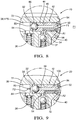
- Said regulation unit 20 takes the form of a mechanically regulated valve 42, represented on the figures 6 to 11 , having a spool valve member 44 slidably adjusted in a valve bore 46 and therein adapted to translate between a first extreme position P1 and, a second extreme position P2.
- the spool valve member 44 is urged toward the first extreme position P1 by a valve spring 48 pushing on an inlet end 50 of the spool member, figure 8 , and, in the opposite direction the spool 44 is urged toward the second extreme position P2, figure 11 , by the pressure in the final outlet channel 38, some pressurized fuel being deviated from said final channel 38 to push onto an outlet end 52 of the spool member.
- the first PT1 and second PT2 pressure thresholds define an operational pressure range OPR of the regulation unit 20. Conclusive tests have been conducted where said range OPR extended between 50 and 100 bars.
- the regulation unit 20 controls the pressure in the high pressure space HPS by controlling an inlet fluid communication F1 enabling access of inlet fuel to the compression chamber 28.
- an inlet aperture 54 is defined as the opening controlled inlet channel 30 into the valve bore 46.
- the movements of the spool member 44 restrict said inlet fluid communication F1 by partially closing said inlet aperture 54 from a non-restricted state or, fully open state, when the spool member 44 is in the first extreme position P1 to, a closed state forbidding any entry of fuel into the compression chamber 28 when the spool member 44 reaches an intermediate position Pi, the pressure in the high pressure space HPS being at an intermediate pressure threshold PTi inferior to the second threshold PT2. Above said intermediate position Pi the inlet fluid communication F1 remains closed.
- the spool member 44 is divided in four cells referenced from right to left C1 to C4. This first function is sketched in figure 1 by the four cells where in cell C1 the inlet is fully open, in the second cell C2 the inlet is limited, while it is fully closed in the third cell C3 and remains closed to the final cell C4.
- Figure 2 illustrates this first function. It is an X-Y graph plotting the evolution of the inlet fluid communication F1 controlling the inlet quantity of fuel admitted in the compression chamber as a function of the pressure in the high pressure space HPS.
- the inlet fluid communication F1 fully closes and no more fuel is admitted the compression chamber, this state being symbolized on the Y axis by number "0".
- said closure of the first fluid communication F1 is indeed limited to some fuel leakages.
- the regulation unit 20 further controls the pressure in the high pressure space HPS by increasing the volume of said high pressure space HPS in opening a second fluid communication F2 to a relief chamber 56 which inner volume adds up to the volume of the high pressure space HPS.
- the regulation unit 20 further controls the pressure in the high pressure space HPS since, the volume of said relief chamber 56 permanently self-adapts to the pressure in the final outlet channel 38, the volume of the relief chamber ranging from null when the second fluid communication F2 is closed, the spool member 44 being in the first extreme position P1 to, a maximum volume when the spool 44 is in the second extreme position P2.
- This auto-regulation, or self-adaptation, of the volume of the high pressure space HPS to the pressure of the high pressure space HPS acts as a damper enabling to amortize pressure waves propagating in the pressurized fuel contained in the high pressure space HPS.
- Figure 3 illustrates the second and third functions in another X-Y graph plot of the evolution of the volume of the high pressure space HPS as a function of the pressure in the high pressure space HPS.
- the second fluid communication F2 is closed, this being symbolized by number "0" on the Y axis and, the volume of the high pressure space HPS is minimal.
- the second fluid communication F2 When the outlet pressure is within the operational pressure range OPR, between the first PT1 and the second PT2 pressure thresholds, the second fluid communication F2 is open and the volume of the relief chamber 56 regularly increases up to a maximum, "MAX" on the Y axis, when pressure in the high pressure space HPS rises to the second pressure threshold PT2, the spool member 44 reaching the second extreme position P2.
- the regulation unit 20 finally controls the pressure in the high pressure space HPS by opening a return fluid communication F3 when the spool member 44 reaches the second extreme position P2.
- the regulation unit 20 further defines a spill channel 58 enabling exit of excess fuel contained in the relief chamber 56 and therefore in the high pressure space HPS. In the second extreme position P2 said spill channel 58 is open, otherwise it is closed.
- the second, third and fourth functions are depicted on figure 1 throughout the cells C1-C4 of the spool, the return fluid communication F3 only opening in the final cell C4 and, between the first C1 and fourth C4 cells the second fluid communication F2 opens the high pressure space HPS to the relief chamber 56 which volumes varies and damps the pressure pulsations propagating within the pressurized fuel.
- Figure 4 illustrates the fourth function in yet another X-Y graph plotting the evolution of the return fluid communication F3 as a function of the pressure in the high pressure space HPS.
- the return fluid communication F3 is closed, "0" on the Y axis and, when the pressure in the high pressure space HPS reaches the second pressure threshold PT2 said return fluid communications F3 opens, symbolized by number "1" on the Y axis.
- the inlet fluid communication F1 is permanently fully open, the second fluid communication F2 is permanently closed and the return fluid communication is also permanently closed.
- the inlet fluid communication F1 is permanently closed, the second fluid communication F2 is open and the volume of the relief chamber 56 is maximum and, the return fluid communication F3 is open.
- the pressure in the high pressure space HPS is regulated by adjusting the inlet fluid communication F1 thus adjusting the inlet flow as a function of the pressure in the high pressure space HPS, and also by increasing the volume of the relief chamber 56 also as a function of the pressure in the high pressure space HPS.
- the pressure in the high pressure space HPS When the pressure in the high pressure space HPS increases into a higher sub-range OPR2 of the operational pressure range OPR, between the intermediate pressure threshold PTi and the second pressure threshold PT2, the pressure in the high pressure space HPS is regulated by closing the inlet fluid communication F1 and jointly increasing the volume of relief chamber 56 still as a function of the pressure in the high pressure space HPS. This continuous increase in relief chamber volume pursues the pressure regulation by tending lowering said pressure when indeed said pressure continues to rise.
- the pump assembly 10 is represented in BDC in figure 6 and in TDC in figure 7 , the pressurizing unit 22 being on the bottom part of the figures while the regulation unit 20 is fixed on the top of it.
- the pressurizing unit 22 comprises a cylindrical body 60 having a large top portion and a downwardly extending narrower turret.
- the bore 24, provided in said pressurizing body 22, extends along the pumping axis X both through the large portion and through the turret, the bore 24 opening in the upper face 62 of the pressurizing body as well as at the lower end of the turret. In the upper face 62, the bore opens in a shallow recess forming a gallery 64 enlarging said opening of the bore.
- the top part of the plunger 26 is slidably arranged in the bore 24 while the bottom end downwardly protrudes out of the pressurizing body 60 toward an end provided with a cam follower 66, or slider, adapted to follow the profile of a cam, not represented.
- a cam follower 66 or slider
- a lip seal 68 preventing fuel leaks to exit and flow out of the pump where oil lubricates the cam area. Said leaks, as mentioned previously, downwardly flow between the plunger 26 and the bore 24 and are collected in the leak return channel 40 provided in the pressurizing body 60 that redirect in the upward direction said fuel leaks toward the pump inlet 16.
- the leak return channel 40 comprises a lower portion in the pressurizing body 60 and an upper portion above.
- the regulation unit 20 also comprises a body 72 provided on its part with a recess defining a cylindrical lateral wall 74 and a bottom face 76, said recess being complementary adjusted to receive the pressurizing body 60 which is engaged and fixed in said recess.
- the upper face 62 of the pressurizing body is sealingly compressed against the bottom face 76 of the recess and, the lateral male cylindrical face of the pressurizing body lies against the lateral female inner face of the wall 74.
- Fixation of the bodies 60, 72 can be done by welding or screwing, provided that complementary threads are provided on the male and female cylindrical faces of the bodies.
- the pump body 14 is the integral assembly of the pressurizing body 60 and of the regulation body 72.
- the central area of the bottom face 76 of the recess, area that is right above the top opening of the bore 24 and above the gallery 64 forms a ceiling 78 for the compression chamber 28.
- the peripheral area surrounding said ceiling 78 is compressed in surface contact against the complementary peripheral area of the upper face 62 of the pressurizing body ensuring sealing of the area.
- the regulation body 72 is further provided, in its upper region, with the valve bore 46 and with the final outlet channel 38 that are horizontally aligned, the valve bore 46 opening on the lateral outer face of the body 72, right of the figure, and the final outlet channel 38 opening at the opposite, left of the figure.
- the second fluid communication F2 takes the form of an opening 80 joining the right end of the final outlet channel 38 to left end of the valve bore 46.
- said opening, or relief opening 80 is surrounded by a seating face 82 that can be rounded or conical and which is provided on the side of the valve bore 46.
- the regulating body 72 is further provided with the controlled inlet channel 30, right of the figure, and with the controlled outlet channel 34, left of the figure, that are both vertically upwardly extend from the ceiling 78 of the compression chamber.
- the controlled inlet channel 30 opens in the valve bore 46 through the inlet aperture 54 that joins the top end of the controlled inlet channel 30 to the horizontal lateral face of the valve bore 46.
- the inlet aperture 54 is surrounded by the seating face previously mentioned when describing the non-return inlet check valve 32.
- said inlet valve 32 which ball is upwardly biased by the inlet valve coil spring against said seating face, thus closing the inlet aperture 54.
- An annular member, press-fitted in the lower region of the controlled inlet channel 30 forms an annular shoulder face against which the bottom end of the spring can bear and be compressed.
- the controlled outlet channel 34 opens in the final outlet channel 38, via an aperture 84 that vertically joins the top end of the controlled outlet channel 34 to the horizontal lateral face of the final outlet channel 38. Also, as already mentioned, in the controlled outlet channel 34 is arranged said outlet valve 36 which ball is downwardly biased by the outlet valve coil spring against a seating face provided with another annular member press-fitted in the lower region of the controlled outlet channel 34. In the upper region, in the vicinity to said aperture 84, the upper end outlet valve coil spring bears against a washer member forming another annular shoulder face against which said spring is compressed.
- the arrangement of the inlet 32 and outlet 36 check valves is done to only enable fuel flow from the inlet toward the compression chamber and, from said compression chamber toward the outlet. The reverse flow is prevented by the check valves.
- the two coil springs have low stiffness just enabling to maintain the ball in place against their seating face but, as soon as fuel pushes the ball in the opening direction, said pushing force overcomes the spring force that further compresses, opening said fuel passage.
- the piston 26 is in BDC and inlet flow enters the compression chamber.
- the inlet valve 32 is open while the outlet valve 36 is closed.
- valve bore 46 is slidably arranged the spool valve member 44 provided on its outlet end 52, left end on the figure, with a ball 86 forming a closing member adapted to sealingly bear against the seating face 82, thus closing the second fluid communication F2.
- the valve spring 48 pushes the spool member 44 in said closing position of the second fluid communication F2.
- the valve spring 48 is compressed between said inlet end 50 of the spool member 44 and an annular member 88 press-fitted in an inlet pipe 90 connected to the pump inlet 16.
- the upper portion of the leak return channel 40 extends in the regulation body 72 from a connection in the lower portion to an outer opening arranged of the pump inlet opening within this inlet pipe 90. Therefore, fuel leakage during operation flows from the compression chamber around the plunger 26, then it reaches the return leak channel 40 prior to exit in the inlet pipe 90 where said leaks merges with the low pressure fuel inlet entering the pump.
- the regulation body 72 is further provided with a tubular outlet connection member 92 fixed around the pump outlet 18 at the opening end, left end of the figure, of the final outlet channel 38.
- the connection member 92 is threaded to enable tightening of the connecting pipe, not represented that, along with the high pressure reservoir is part of the high pressure space HPS.
- the regulating valve 42 and the spool member 44 are now further described in reference to the figures 8 to 11 .
- the spool member 44 is a cylindrical member horizontally adjusted to slide within the valve bore 46.
- the opening end of the bore 46 in the peripheral face of the regulation body 72 is slightly enlarged, the leak return channel 40 opening in said enlarged entry 94, further motivation for having said enlarged entry 94 of the bore being explained afterward.
- the spool member 44 extends from its inlet end 50, right end of the figure, to its outlet end 52, left end, wherein is crimped the ball 86 forming the closing member of the second fluid communication F2. About half way between its inlet and outlet ends, the spool member 44 is further provided with a surrounding annular inlet groove 96 opening in the outer cylindrical face of the spool.
- the spool member 44 is further provided with an inner inlet channel 98 extending from the inlet end 50 of the spool member to an opening provided in a side face of the inlet groove 96.
- the spill channel 58 is arranged within the spool member 44, opening in the outlet end 52, beside the ball 86, and extending to a rear end opening 100 that is arranged in the cylindrical peripheral face of the spool member, in the close vicinity to the inlet end 50.
- said spill channel 58 comprises a front portion that surrounds the ball 86, then a straight axial portion and finally a radial portion leading to said rear end opening 100.
- the inner inlet channel 98 could only comprise one straight portion drilled angularly from the rear end opening 100 to the outlet end 52 of the spool member.
- Figure 8 illustrates the first function of the regulation unit 20, where the pressure in the high pressure space HPS is below the first pressure threshold PT1, the spool member 44 being in the first extreme position P1, the inlet fluid communication F1 is fully open, the second fluid communication F2 and the outlet fluid communication F3 are closed.
- the inlet aperture 54 opens in the inlet groove 96 and the fuel flowing from the inlet pipe 90 to the compression chamber 28 has a non-restricted path, this is represented on the figure by the large arrow A1. Said fuel easily flows in the inner inlet channel 98 then, in the inlet groove 96, it passes the inlet aperture 54 easily pushing the ball of the inlet valve 32 to flow in the controlled inlet channel 30 prior to entering the compression chamber 28.
- An advantage for having the inlet groove 96 over a simple radial opening is that whatever is the angular position of the spool member 44 in the valve bore, the inlet aperture 54 always opens in said inlet groove. Consequently angular positioning of the spool member relative to the valve bore is not required. In the situation of figure 8 , the pressure in the high pressure space HPS is not regulated, all parameters being constant.
- Figure 9 illustrates the second function of the regulation unit 20, where the pressure in the high pressure space HPS is superior to the first pressure threshold PT1, within the lower sub-range OPR1, the inlet fluid communication F1 is restricted, the second fluid communication F2 is open and the outlet fluid communication F3 is closed.
- the pressure in the high pressure space HPS is regulated by the addition of the volume of the relief chamber to the high pressure space HPS and also by, the restriction of the inlet flow. Both said addition and said restriction are continuous function dependent upon the pressure in the high pressure space HPS.
- Figure 10 illustrates the third function of the regulation unit 20, where the pressure in the high pressure space HPS has reached the intermediate pressure threshold PTi, the inlet fluid communication F1 is closed, the second fluid communication F2 is open and the outlet fluid communication F3 is closed.
- the pressure in the high pressure space HPS is regulated by the further continuous addition of the volume of the relief chamber to the high pressure space HPS and, by closing the inlet flow.
- Figure 11 illustrates the fourth function of the regulation unit 20, where the pressure in the high pressure space HPS has reached the second pressure threshold PT2, the inlet fluid communication F1 remains closed, the second fluid communication F2 is open and the outlet fluid communication F3 is now open.
- the spool member 44 of the described embodiment is further presented in the figures 12 to 15 enabling to visualize the inner inlet channel 98, the spill channel 56, the ball 86, the outer cylindrical face and the inlet groove 96.
- the rear opening 100 of the spill channel indeed opens in a spill groove 102 provided in the spool member
- said inlet end 50 is provided with a protrusion 104 around which the last turns of the valve spring 48 engage.
Landscapes
- Engineering & Computer Science (AREA)
- Mechanical Engineering (AREA)
- General Engineering & Computer Science (AREA)
- Chemical & Material Sciences (AREA)
- Combustion & Propulsion (AREA)
- Fuel-Injection Apparatus (AREA)
- Safety Valves (AREA)
Description
- The present invention relates to a self-regulated fuel pump.
- Fuel injection equipment of internal combustion engine comprise high pressure pump fluidly connected between a low pressure fuel system such as a transfer pump immersed in a fuel tank, and a high pressure system comprising a reservoir, such as a well-known common-rail, in which is stored pressurized fuel prior to be delivered and sprayed by fuel injectors into compression chambers of the engine.
- A command unit receiving a plurality of information signals from the engine and the vehicle generates command signals for adjusting operational parameters of the injection equipment to the engine demand.
- For instance, to match the engine demand for speed, acceleration or deceleration of the vehicle, the quantity and pressure of fuel to be sprayed is computed by the command unit which in turn generates orders commanding each component of the injection equipment, transfer pump, high pressure pump, injectors, an operational behavior adapted to said engine demand.
- In gasoline engines, said quantity and volume of pressurized fuel is regulated by the command unit via electrical means such as an electrical pump or an electrical spill valve. In addition to the cost incurred because of said electrical actuators, the acoustic noise generated by the motions commanded has become a major issue.
- Self-regulated fuel pumps are known from
WO2012089511 A1 andJP2010163888 A - Accordingly, it is an object of the present invention to resolve the above mentioned problems in providing a self-regulated fuel pump assembly of a fuel injection system of an internal combustion engine, the pump assembly being adapted to be arranged between a low pressure tank and a high pressure reservoir, the pump comprising a pump body defining and inlet fluid communication controlled by an inlet valve for enabling in use, an inlet fuel quantity to enter a compression chamber, wherein said fuel is pressurized by a piston varying the volume of said compression chamber and, wherefrom pressurized fuel is expelled and delivered into a high pressure space, comprising the high pressure reservoir, via an outlet fluid communication controlled by an outlet valve.
- The fuel pump further comprises a mechanical regulating valve arranged in the pump body and adapted to modulate, in use, the pressure in a high pressure space so that, said pressure matches the engine demand, said modulation requiring adjustment of the inlet fuel quantity, adjustment of the volume of the high pressure space wherein is stored the pressurized fuel and, control of a return fluid communication enabling fuel to exit the high pressure reservoir.
- Also, in use, the mechanical regulating valve is active within an operational pressure range extending between a first pressure threshold below which the inlet fluid communication is fully open and, a second pressure threshold above which opens the return fluid communication.
- Also, in use, throughout the operational pressure range the pressure in the high pressure reservoir is adjusted to match the engine demand by adjusting the volume of the high pressure space as a function of the pressure in said high pressure space.
- Also, in use, when the pressure in the high pressure space is within a lower sub-range closer to the first pressure threshold of the operational pressure range, the pressure in the high pressure reservoir is further adjusted to the engine demand by restricting the inlet fluid communication thus decreasing the inlet quantity of fuel entering in the compression chamber.
- Also, the inlet fluid communication is continuously varied within said lower sub-range.
- Also, in use, when the pressure in the high pressure space is within a higher sub-range closer to the second pressure threshold of the operational pressure range, the pressure in the high pressure reservoir is further adjusted to match the engine demand by closing the inlet fluid communication thus preventing fuel entry in the compression chamber.
- Also, the lower sub-range extends from the first pressure threshold to an intermediate pressure threshold and, the higher sub-range extends from said intermediate pressure threshold to the second pressure threshold.
- Also, the mechanical regulating valve comprises a spool valve member slidably arranged in a valve bore provided in the pump body, said arrangement controlling the inlet fluid communication, the volume of the high pressure space and, the return fluid communication.
- Also, the mechanical regulating valve further comprises a valve spring biasing the spool valve member toward a first extreme position where the inlet fluid communication is fully open and the return fluid communication is closed, and wherein in use, the pressure in the high pressure space bias the spool valve member toward a second extreme position where the inlet fluid communication is closed and the return fluid communication is open, the biasing force of the spring being opposed to the biasing force of the outlet pressure.
- Also, the spool valve member has a cylindrical lateral face extending from a front end, or outlet end, to a back end, or inlet end, said front end being provided with a closing member adapted to sealingly seat against a seating face of the pump body, said seating face surrounding a relief opening of the return fluid communication and wherein, when the spool valve member is in the first extreme position the closing member sealingly seats on the seating face closing said relief opening.
- Also, the return fluid communication is further provided with a rear opening defined at an end of a spill channel arranged in the spool valve member the opening entry of said spill channel being in the front end of the spool valve member, in the close vicinity to the closing member and wherein, said rear opening only opens when the spool valve member is in the second extreme position enabling fuel to return from the relief chamber to the low pressure inlet.
- Also, the end of said spill channel opens in the lateral face of the spool valve member, the opening of said end being closed by the face of the valve bore against which complementary slides the lateral face of the spool valve member and wherein, the rear opening of the return fluid communication only opens when the spool valve member is in the second extreme position, the rear end of the spill channel facing the opening of the return conduit.
- Also, the spool valve member further comprises an inner inlet channel extending inside the spool valve member from the back end toward an opening in the lateral face of the spool valve member and wherein, the controlled inlet channel wherein is arranged the inlet valve opens at one end in the compression chamber and, at the opposite end in the valve bore face via an inlet aperture, the inlet fluid communication being open when said opening of the inner inlet channel faces said inlet aperture.
- Also, said opening of the inner inlet channel is defined in an annular inlet groove provided in the lateral face of the spool member and wherein, when being in the first extreme position of the spool valve member, the inlet aperture faces said inlet groove.
- Also, when the pressure in the high pressure space varies within the lower sub-range of the operational pressure range, the spool valve member slides in the valve bore, the cylindrical lateral face of the spool member partially covering the inlet aperture of the controlled inlet channel, restricting the inlet fluid communication.
- Also, when the pressure in the high pressure space increases within the higher sub-range of the operational pressure range, the spool valve member slides in the valve bore the cylindrical lateral face totally covering the inlet aperture of the controlled inlet channel thus closing the inlet fluid communication.
- Also, when the pressure in the high pressure space rises, the volume of the high pressure space increases by the additional space of a relief chamber comprised between the front end of the spool valve member and the seating face of the pump body.
- Also, the inlet valve is a one-way check valve forbidding to fuel pressurized in the compression chamber to flow back toward the inlet and wherein, the outlet valve is another one-way check valve forbidding high pressure fuel contained in the high pressure space to flow back to the compression chamber.
- The present invention is now described by way of example with reference to the accompanying drawings in which:
-
Figure 1 is a schematic hydraulic of a fuel injection system as per the invention. -
Figure 2 is a plot of evolution of an inlet fluid communication of the equipment offigure 1 as a function of pressure. -
Figure 3 is a plot of evolution of the volume of a high pressure space of the equipment offigure 1 as a function of pressure. -
Figure 4 is a plot of evolution of a return fluid communication of the equipment offigure 1 as a function of pressure. -
Figure 5 is a table summarizing the domain in which regulation of the pressure in the high pressure space occurs for the equipment offigure 1 . -
Figures 6 and 7 are axial sections of a pump as per a preferred embodiment of the invention,figure 6 representing the pump in BDT andfigure 7 in TDC. -
Figures 8 to 11 are magnified area of the pump offigures 6 and 7 , the figures illustrating different phase of operation of a regulation unit of the pump. -
Figure 12 to 15 are further details of a spool valve member of the regulation unit of the pump offigures 6 to 11 . - In reference to the figures is described a self-regulated high
pressure pump assembly 10 adapted to be arranged in fluid communication in an injection fuel equipment, not represented. Upstream thepump 10 is a low pressure system comprising a lowpressure fuel tank 12 and a transfer pump and, downstream thepump 10 is a high pressure system for storing and delivering the pressurized fuel, said system typically comprising a high pressure reservoir, often referred as a "common rail" to which are fluidly connected a plurality of fuel injectors. - The general hydraulic diagram of
figure 1 enables to schematically identify the functions fulfilled by the self-regulatedpump 10 and its components. - The
pump 10 has apump body 14 provided with apump inlet 16 and apump outlet 18 and, between said inlet and outlet, are arranged aregulation unit 20 and a pressurizingunit 22. - The pressurizing
unit 22 comprises abore 24 in which aplunger 26, forming piston, is adapted to reciprocal translations along a pumping axis X performing therein a pumping cycle between a bottom dead centre (BDC) position and a top dead centre (TDC) position. Acompression chamber 28, which inner volume is varied during said pumping cycle, is defined between an end of thebore 24 and thepiston 26. - Fuel at low pressure, few bars for instance, enters the
pump body 14 via thepump inlet 16, flows through theregulation unit 20 that is described afterward and, enters thecompression chamber 28 via a controlledinlet channel 30 controlled by aninlet valve 32. Once pressurized, for instance at 100 bars, the fuel exits thecompression chamber 28 via a controlledoutlet channel 34 controlled by anoutlet valve 36. Said controlledchannel 34 opens in afinal outlet channel 38 extending toward thepump outlet 18 adapted to be connected to a pipe, not represented, connecting to the high pressure reservoir. Saidfinal outlet channel 38 is part of a high pressure space HPS comprising the high pressure reservoir, the connecting pipe and thisfinal outlet channel 38 integral to thepump body 14. - Both inlet and
outlet valves valves inlet 16 to theoutlet 18 and, to forbid counter flow. Between the lateral face of thepiston 26 and thebore 24 is kept a functional clearance through which, in use, fuel leaks from thecompression chamber 28, said leaks being collected into areturn leak channel 40 flowing back toward thepump inlet 16. - The
regulation unit 20 is arranged in thepump body 14 in fluid communication between thepump inlet 16 and controlledinlet channel 30. It aims at regulating the pressure in the high pressure space HPS by fulfilling functions further detailed afterward. - Said
regulation unit 20 takes the form of a mechanically regulatedvalve 42, represented on thefigures 6 to 11 , having aspool valve member 44 slidably adjusted in avalve bore 46 and therein adapted to translate between a first extreme position P1 and, a second extreme position P2. Thespool valve member 44 is urged toward the first extreme position P1 by avalve spring 48 pushing on aninlet end 50 of the spool member,figure 8 , and, in the opposite direction thespool 44 is urged toward the second extreme position P2,figure 11 , by the pressure in thefinal outlet channel 38, some pressurized fuel being deviated from saidfinal channel 38 to push onto anoutlet end 52 of the spool member. - Below a first pressure threshold PT1 in the high pressure space HPS, the force of the
valve spring 48 overcomes the opposite force of the pressure and, thespool member 44 remains in the first extreme position P1. - When the pressure in the high pressure space HPS overcomes the first threshold PT1, the force urged on the
outlet end 52 of the spool member surpasses the spring force and thespool member 44 lifts off the first extreme position P1. - When the pressure in the high pressure space HPS continues to rise and reaches a second pressure threshold PT2, the force urged by said pressure overcomes the spring force that is fully compressed and, the
spool member 44 is pushed to the second extreme position P2. - The first PT1 and second PT2 pressure thresholds define an operational pressure range OPR of the
regulation unit 20. Conclusive tests have been conducted where said range OPR extended between 50 and 100 bars. - The functions fulfilled by the
regulation unit 20 are now described in reference tofigure 1 and tofigures 2 to 5 . - Firstly, the
regulation unit 20 controls the pressure in the high pressure space HPS by controlling an inlet fluid communication F1 enabling access of inlet fuel to thecompression chamber 28. Indeed, between thepump inlet 16 and the controlledinlet channel 30, aninlet aperture 54 is defined as the opening controlledinlet channel 30 into the valve bore 46. The movements of thespool member 44 restrict said inlet fluid communication F1 by partially closing saidinlet aperture 54 from a non-restricted state or, fully open state, when thespool member 44 is in the first extreme position P1 to, a closed state forbidding any entry of fuel into thecompression chamber 28 when thespool member 44 reaches an intermediate position Pi, the pressure in the high pressure space HPS being at an intermediate pressure threshold PTi inferior to the second threshold PT2. Above said intermediate position Pi the inlet fluid communication F1 remains closed. - In
figure 1 thespool member 44 is divided in four cells referenced from right to left C1 to C4. This first function is sketched infigure 1 by the four cells where in cell C1 the inlet is fully open, in the second cell C2 the inlet is limited, while it is fully closed in the third cell C3 and remains closed to the final cell C4. -
Figure 2 illustrates this first function. It is an X-Y graph plotting the evolution of the inlet fluid communication F1 controlling the inlet quantity of fuel admitted in the compression chamber as a function of the pressure in the high pressure space HPS. - When the outlet pressure, on the horizontal X axis, is below the first pressure threshold PT1, the inlet fluid communication F1 is fully open and the inlet quantity is maximum, this being symbolized on the Y axis by the number "1".
- When the outlet pressure is between the first PT1 and the intermediate PTi pressure thresholds the inlet fluid communication F1 restricts and the inlet quantity decreases. The plot of
figure 2 is a straight line for this portion of the curve while in reality the function may show more roundness. - Above the intermediate pressure threshold PTi, the inlet fluid communication F1 fully closes and no more fuel is admitted the compression chamber, this state being symbolized on the Y axis by number "0". Considering the embodiment detailed below, said closure of the first fluid communication F1 is indeed limited to some fuel leakages.
- Secondly, the
regulation unit 20 further controls the pressure in the high pressure space HPS by increasing the volume of said high pressure space HPS in opening a second fluid communication F2 to arelief chamber 56 which inner volume adds up to the volume of the high pressure space HPS. - Thirdly, the
regulation unit 20 further controls the pressure in the high pressure space HPS since, the volume of saidrelief chamber 56 permanently self-adapts to the pressure in thefinal outlet channel 38, the volume of the relief chamber ranging from null when the second fluid communication F2 is closed, thespool member 44 being in the first extreme position P1 to, a maximum volume when thespool 44 is in the second extreme position P2. This auto-regulation, or self-adaptation, of the volume of the high pressure space HPS to the pressure of the high pressure space HPS acts as a damper enabling to amortize pressure waves propagating in the pressurized fuel contained in the high pressure space HPS. -
Figure 3 illustrates the second and third functions in another X-Y graph plot of the evolution of the volume of the high pressure space HPS as a function of the pressure in the high pressure space HPS. - As long as the outlet pressure is below the first pressure threshold PT1, the second fluid communication F2 is closed, this being symbolized by number "0" on the Y axis and, the volume of the high pressure space HPS is minimal.
- When the outlet pressure is within the operational pressure range OPR, between the first PT1 and the second PT2 pressure thresholds, the second fluid communication F2 is open and the volume of the
relief chamber 56 regularly increases up to a maximum, "MAX" on the Y axis, when pressure in the high pressure space HPS rises to the second pressure threshold PT2, thespool member 44 reaching the second extreme position P2. - Fourthly, the
regulation unit 20 finally controls the pressure in the high pressure space HPS by opening a return fluid communication F3 when thespool member 44 reaches the second extreme position P2. Indeed, theregulation unit 20 further defines aspill channel 58 enabling exit of excess fuel contained in therelief chamber 56 and therefore in the high pressure space HPS. In the second extreme position P2 saidspill channel 58 is open, otherwise it is closed. - The second, third and fourth functions are depicted on
figure 1 throughout the cells C1-C4 of the spool, the return fluid communication F3 only opening in the final cell C4 and, between the first C1 and fourth C4 cells the second fluid communication F2 opens the high pressure space HPS to therelief chamber 56 which volumes varies and damps the pressure pulsations propagating within the pressurized fuel. -
Figure 4 illustrates the fourth function in yet another X-Y graph plotting the evolution of the return fluid communication F3 as a function of the pressure in the high pressure space HPS. - As long as the pressure in the high pressure space HPS is below the second pressure threshold PT2, the return fluid communication F3 is closed, "0" on the Y axis and, when the pressure in the high pressure space HPS reaches the second pressure threshold PT2 said return fluid communications F3 opens, symbolized by number "1" on the Y axis.
- Regulation of the pressure in the high pressure space HPS is achieved by combining all the functions. This is summarized in
figure 5 that is a table in which: - the first line is the pressure in the high pressure space HPS as it is scaled in X axis of the plots of
figures 2, 3 and 4 ; - the second line is the state of the inlet fluid communication F1 as plotted in
figure 2 ; - the third line is the state of the second fluid communication and the volume of the
relief chamber 56 as plotted infigure 3 ; - the fourth line is the state of the return fluid communication F3 as plotted in
figure 4 and, - the bottom line is the state of regulation of the pressure in the high pressure space HPS where, outside the operational pressure range OPR there is no regulation provided since none of the parameters varies but, when return fluid communication F3 opens the actual pressure in the high pressure space HPS cannot increase any more.
- Below the first pressure threshold PT1 the inlet fluid communication F1 is permanently fully open, the second fluid communication F2 is permanently closed and the return fluid communication is also permanently closed.
- Above the second pressure threshold PT2 the inlet fluid communication F1 is permanently closed, the second fluid communication F2 is open and the volume of the
relief chamber 56 is maximum and, the return fluid communication F3 is open. - Within the operational pressure range OPR, in a lower sub-range OPR1 between the first pressure threshold PT1 and the intermediate pressure threshold PTi, the pressure in the high pressure space HPS is regulated by adjusting the inlet fluid communication F1 thus adjusting the inlet flow as a function of the pressure in the high pressure space HPS, and also by increasing the volume of the
relief chamber 56 also as a function of the pressure in the high pressure space HPS. These two parameters combine and tend to regulate the pressure in the high pressure space HPS by lowering said pressure when indeed it is trying to increase. - When the pressure in the high pressure space HPS increases into a higher sub-range OPR2 of the operational pressure range OPR, between the intermediate pressure threshold PTi and the second pressure threshold PT2, the pressure in the high pressure space HPS is regulated by closing the inlet fluid communication F1 and jointly increasing the volume of
relief chamber 56 still as a function of the pressure in the high pressure space HPS. This continuous increase in relief chamber volume pursues the pressure regulation by tending lowering said pressure when indeed said pressure continues to rise. - A non-limiting embodiment is now described more in detailed in reference to
figures 6 to 15 . - The
pump assembly 10 is represented in BDC infigure 6 and in TDC infigure 7 , the pressurizingunit 22 being on the bottom part of the figures while theregulation unit 20 is fixed on the top of it. - The pressurizing
unit 22 comprises acylindrical body 60 having a large top portion and a downwardly extending narrower turret. Thebore 24, provided in said pressurizingbody 22, extends along the pumping axis X both through the large portion and through the turret, thebore 24 opening in theupper face 62 of the pressurizing body as well as at the lower end of the turret. In theupper face 62, the bore opens in a shallow recess forming agallery 64 enlarging said opening of the bore. The top part of theplunger 26 is slidably arranged in thebore 24 while the bottom end downwardly protrudes out of the pressurizingbody 60 toward an end provided with acam follower 66, or slider, adapted to follow the profile of a cam, not represented. In the turret is arranged alip seal 68 preventing fuel leaks to exit and flow out of the pump where oil lubricates the cam area. Said leaks, as mentioned previously, downwardly flow between theplunger 26 and thebore 24 and are collected in theleak return channel 40 provided in the pressurizingbody 60 that redirect in the upward direction said fuel leaks toward thepump inlet 16. As visible on the figures, theleak return channel 40 comprises a lower portion in the pressurizingbody 60 and an upper portion above. Amain valve spring 70 engaged around the turret and compressed between a face of the top portion of thebody 60 and thecam follower 66 urges theplunger 26 toward the BDC position and ensures that the cam follower remains in contact with the cam. In use, when the cam rotates it imparts to theplunger 26, via thecam follower 66 the pumping cycle displacements between BDC and TDC. - The
regulation unit 20 also comprises abody 72 provided on its part with a recess defining a cylindrical lateral wall 74 and abottom face 76, said recess being complementary adjusted to receive the pressurizingbody 60 which is engaged and fixed in said recess. Theupper face 62 of the pressurizing body is sealingly compressed against thebottom face 76 of the recess and, the lateral male cylindrical face of the pressurizing body lies against the lateral female inner face of the wall 74. Fixation of thebodies pump body 14 is the integral assembly of the pressurizingbody 60 and of theregulation body 72. The central area of thebottom face 76 of the recess, area that is right above the top opening of thebore 24 and above thegallery 64 forms a ceiling 78 for thecompression chamber 28. The peripheral area surrounding said ceiling 78 is compressed in surface contact against the complementary peripheral area of theupper face 62 of the pressurizing body ensuring sealing of the area. - As visible on the figure, and following the non-limiting and non-binding top-down orientation presented, the
regulation body 72 is further provided, in its upper region, with the valve bore 46 and with thefinal outlet channel 38 that are horizontally aligned, the valve bore 46 opening on the lateral outer face of thebody 72, right of the figure, and thefinal outlet channel 38 opening at the opposite, left of the figure. The second fluid communication F2 takes the form of anopening 80 joining the right end of thefinal outlet channel 38 to left end of the valve bore 46. Furthermore, said opening, orrelief opening 80, is surrounded by aseating face 82 that can be rounded or conical and which is provided on the side of the valve bore 46. - The regulating
body 72 is further provided with the controlledinlet channel 30, right of the figure, and with the controlledoutlet channel 34, left of the figure, that are both vertically upwardly extend from the ceiling 78 of the compression chamber. - The controlled
inlet channel 30 opens in the valve bore 46 through theinlet aperture 54 that joins the top end of the controlledinlet channel 30 to the horizontal lateral face of the valve bore 46. At the end of the controlledinlet channel 30, theinlet aperture 54 is surrounded by the seating face previously mentioned when describing the non-returninlet check valve 32. Also, as already mentioned, in the controlledinlet channel 30 is arranged saidinlet valve 32 which ball is upwardly biased by the inlet valve coil spring against said seating face, thus closing theinlet aperture 54. An annular member, press-fitted in the lower region of the controlledinlet channel 30 forms an annular shoulder face against which the bottom end of the spring can bear and be compressed. - The controlled
outlet channel 34 opens in thefinal outlet channel 38, via anaperture 84 that vertically joins the top end of the controlledoutlet channel 34 to the horizontal lateral face of thefinal outlet channel 38. Also, as already mentioned, in the controlledoutlet channel 34 is arranged saidoutlet valve 36 which ball is downwardly biased by the outlet valve coil spring against a seating face provided with another annular member press-fitted in the lower region of the controlledoutlet channel 34. In the upper region, in the vicinity to saidaperture 84, the upper end outlet valve coil spring bears against a washer member forming another annular shoulder face against which said spring is compressed. - The arrangement of the
inlet 32 andoutlet 36 check valves is done to only enable fuel flow from the inlet toward the compression chamber and, from said compression chamber toward the outlet. The reverse flow is prevented by the check valves. The two coil springs have low stiffness just enabling to maintain the ball in place against their seating face but, as soon as fuel pushes the ball in the opening direction, said pushing force overcomes the spring force that further compresses, opening said fuel passage. - In
figure 6 thepiston 26 is in BDC and inlet flow enters the compression chamber. Theinlet valve 32 is open while theoutlet valve 36 is closed. - In
figure 7 the piston has moved upwardly to the TDC, the fuel in the compression chamber is pressurized, the inlet valve is closed and the outlet valve is open. - In the valve bore 46 is slidably arranged the
spool valve member 44 provided on itsoutlet end 52, left end on the figure, with aball 86 forming a closing member adapted to sealingly bear against theseating face 82, thus closing the second fluid communication F2. On theinlet end 50, right end on the figure, thevalve spring 48 pushes thespool member 44 in said closing position of the second fluid communication F2. Thevalve spring 48 is compressed between saidinlet end 50 of thespool member 44 and anannular member 88 press-fitted in aninlet pipe 90 connected to thepump inlet 16. - Also, as previously mentioned, the upper portion of the
leak return channel 40 extends in theregulation body 72 from a connection in the lower portion to an outer opening arranged of the pump inlet opening within thisinlet pipe 90. Therefore, fuel leakage during operation flows from the compression chamber around theplunger 26, then it reaches thereturn leak channel 40 prior to exit in theinlet pipe 90 where said leaks merges with the low pressure fuel inlet entering the pump. - The
regulation body 72 is further provided with a tubularoutlet connection member 92 fixed around thepump outlet 18 at the opening end, left end of the figure, of thefinal outlet channel 38. Theconnection member 92 is threaded to enable tightening of the connecting pipe, not represented that, along with the high pressure reservoir is part of the high pressure space HPS. - The regulating
valve 42 and thespool member 44 are now further described in reference to thefigures 8 to 11 . - As represented on said figures, the
spool member 44 is a cylindrical member horizontally adjusted to slide within the valve bore 46. The opening end of thebore 46 in the peripheral face of theregulation body 72 is slightly enlarged, theleak return channel 40 opening in saidenlarged entry 94, further motivation for having saidenlarged entry 94 of the bore being explained afterward. - The
spool member 44 extends from itsinlet end 50, right end of the figure, to itsoutlet end 52, left end, wherein is crimped theball 86 forming the closing member of the second fluid communication F2. About half way between its inlet and outlet ends, thespool member 44 is further provided with a surroundingannular inlet groove 96 opening in the outer cylindrical face of the spool. - The
spool member 44 is further provided with aninner inlet channel 98 extending from theinlet end 50 of the spool member to an opening provided in a side face of theinlet groove 96. - Furthermore, the
spill channel 58 is arranged within thespool member 44, opening in theoutlet end 52, beside theball 86, and extending to a rear end opening 100 that is arranged in the cylindrical peripheral face of the spool member, in the close vicinity to theinlet end 50. As visible on the figure, saidspill channel 58 comprises a front portion that surrounds theball 86, then a straight axial portion and finally a radial portion leading to saidrear end opening 100. Alternatively, theinner inlet channel 98 could only comprise one straight portion drilled angularly from the rear end opening 100 to the outlet end 52 of the spool member. -
Figure 8 illustrates the first function of theregulation unit 20, where the pressure in the high pressure space HPS is below the first pressure threshold PT1, thespool member 44 being in the first extreme position P1, the inlet fluid communication F1 is fully open, the second fluid communication F2 and the outlet fluid communication F3 are closed. - Indeed, in said position of the spool member, the
inlet aperture 54 opens in theinlet groove 96 and the fuel flowing from theinlet pipe 90 to thecompression chamber 28 has a non-restricted path, this is represented on the figure by the large arrow A1. Said fuel easily flows in theinner inlet channel 98 then, in theinlet groove 96, it passes theinlet aperture 54 easily pushing the ball of theinlet valve 32 to flow in the controlledinlet channel 30 prior to entering thecompression chamber 28. An advantage for having theinlet groove 96 over a simple radial opening is that whatever is the angular position of thespool member 44 in the valve bore, theinlet aperture 54 always opens in said inlet groove. Consequently angular positioning of the spool member relative to the valve bore is not required. In the situation offigure 8 , the pressure in the high pressure space HPS is not regulated, all parameters being constant. -
Figure 9 illustrates the second function of theregulation unit 20, where the pressure in the high pressure space HPS is superior to the first pressure threshold PT1, within the lower sub-range OPR1, the inlet fluid communication F1 is restricted, the second fluid communication F2 is open and the outlet fluid communication F3 is closed. - Indeed, in said position of the
spool member 44, theball 86 no longer seats on theseating face 82, therelief opening 80 is open and the high pressure space HPS increases by the volume of therelief chamber 56 that is between the spool member and therelief opening 80. Also, theinlet groove 96 having also moved backward toward the inlet, theinlet aperture 54 is now partially covered and partially closed by the outer cylindrical face of the spool member, therefore the inlet path above described is restricted, this being represented on the figure by the thinner arrow A2. - Furthermore, as in the situation of
figure 8 , therear opening 100 of the spill orifice is closed by the cylindrical face of the valve bore 46. The fuel that has entered therelief chamber 56 cannot exit, the third fluid communication F3 remaining closed. - In the situation of
figure 9 , the pressure in the high pressure space HPS is regulated by the addition of the volume of the relief chamber to the high pressure space HPS and also by, the restriction of the inlet flow. Both said addition and said restriction are continuous function dependent upon the pressure in the high pressure space HPS. -
Figure 10 illustrates the third function of theregulation unit 20, where the pressure in the high pressure space HPS has reached the intermediate pressure threshold PTi, the inlet fluid communication F1 is closed, the second fluid communication F2 is open and the outlet fluid communication F3 is closed. - Indeed, in said position of the
spool member 44 has moved backward in regards offigure 9 , theinlet groove 96 has continued to move backward and theinlet aperture 54 is now totally covered and totally closed by the outer cylindrical face of the spool member, therefore the inlet path above described is closed, this being represented by the very thin arrow A3 and the "X" marking said closure. Also therelief chamber 56 has continued to enlarge offering even more space to the high pressure space HPS. - Furthermore, as in the previous situations of
figures 8 and 9 , therear opening 100 of the spill orifice remains closed by the cylindrical face of the valve bore 46. The fuel in therelief chamber 56 cannot exit, the third fluid communication F3 remaining closed. - In the situation of
figure 10 , the pressure in the high pressure space HPS is regulated by the further continuous addition of the volume of the relief chamber to the high pressure space HPS and, by closing the inlet flow. -
Figure 11 illustrates the fourth function of theregulation unit 20, where the pressure in the high pressure space HPS has reached the second pressure threshold PT2, the inlet fluid communication F1 remains closed, the second fluid communication F2 is open and the outlet fluid communication F3 is now open. - Indeed, in said position of the
spool member 44 has moved backward to the second extreme position P2, theinlet aperture 54 is totally covered closed by the outer cylindrical face of the spool member, therelief chamber 56 has continued to enlarge offering even more space to the high pressure space HPS and, therear opening 100 of thespill channel 58 is now in theenlarged entry 94 of the bore which opens thespill orifice 58 and the return fluid communication F3, this being represented by arrow A4. - In the situation of
figure 11 , the pressure in the high pressure space HPS is rapidly lowered by enabling excess of fuel to return toward the low pressure inlet. This opening of the return fluid communication F3 is a safety function preventing the pressure to rise too much, especially in so called hot soak condition when, a hot engine is stopped, the heat continuing to transfer to the high pressure space HPS wherein fuel remains. Under said heat condition pressure of the fuel rises and but is limited by opening of said return fluid communication F3. - The
spool member 44 of the described embodiment is further presented in thefigures 12 to 15 enabling to visualize theinner inlet channel 98, thespill channel 56, theball 86, the outer cylindrical face and theinlet groove 96. - For similar advantage of non-angular orientation of the spool member in the valve bore, the
rear opening 100 of the spill channel indeed opens in aspill groove 102 provided in the spool member - To secure the positioning of the
valve spring 48 against theinlet end 50 of the spool member, saidinlet end 50 is provided with aprotrusion 104 around which the last turns of thevalve spring 48 engage. -
- X
- pumping axis
- BDC
- bottom dead centre
- TDC
- top dead centre
- P1
- first extreme position
- P2
- second extreme position
- Pi
- intermediate position
- HPS
- high pressure space
- PT1
- first pressure threshold
- PT2
- second pressure threshold
- PTi
- intermediate pressure threshold
- OPR
- operational pressure range
- OPR1
- lower sub-range
- OPR2
- higher sub-range
- F1
- inlet fluid communication
- F2
- second fluid communication
- F3
- return fluid communication
- 10
- pump assembly
- 12
- low pressure fuel tank
- 14
- pump body
- 16
- pump inlet
- 18
- pump outlet
- 20
- regulation unit
- 22
- pressurizing unit
- 24
- bore
- 26
- plunger - piston
- 28
- compression chamber
- 30
- controlled inlet channel
- 32
- inlet valve
- 34
- controlled outlet channel
- 36
- outlet valve
- 38
- final outlet channel
- 40
- leak return channel
- 42
- mechanically regulated valve
- 44
- spool valve member
- 46
- valve bore
- 48
- valve spring
- 50
- inlet end of the spool member
- 52
- outlet end of the spool member
- 54
- inlet aperture
- 56
- relief chamber
- 58
- spill channel
- 60
- pressurizing body
- 62
- upper face of the pressurizing body
- 64
- gallery
- 66
- cam follower
- 68
- lip seal
- 70
- main valve spring
- 72
- regulation body
- 74
- cylindrical lateral wall
- 76
- bottom face
- 78
- ceiling of the compression chamber
- 80
- opening - relief opening
- 82
- seating face
- 84
- aperture of the controlled outel channel
- 86
- ball - closing member of the spool
- 88
- annular member
- 90
- inlet pipe
- 92
- outlet connection member
- 94
- enlarged entry of the bore
- 96
- inlet groove
- 98
- inner inlet channel
- 100
- rear opening of the spill channel
- 102
- spill groove
- 104
- protrusion
Claims (14)
- Self-regulated fuel pump assembly (10) of a fuel injection system of an internal combustion engine, the pump assembly (10) being adapted to be arranged between a low pressure tank (12) and a high pressure reservoir, the pump comprising a pump body (14, 60, 72) defining an inlet fluid communication (F1) controlled by an inlet valve (32) for enabling in use, an inlet fuel quantity to enter a compression chamber (28), wherein said fuel is pressurized by a piston (26) varying the volume of said compression chamber (28) and, wherefrom pressurized fuel is expelled and delivered into a high pressure space (HPS), comprising the high pressure reservoir, via an outlet fluid communication controlled by an outlet valve (36), wherein the fuel pump (10) further comprises a mechanical regulating valve (42) arranged in the pump body (14) and adapted to modulate, in use, the pressure in a high pressure space (HPS) so that, said pressure matches the engine demand, said modulation requiring adjustment of the inlet fuel quantity, adjustment of the volume of the high pressure space (HPS) wherein is stored the pressurized fuel and, control of a return fluid communication (F3) enabling fuel to exit the high pressure reservoir and,
wherein the mechanical regulating valve (42) comprises a spool valve member (44) slidably arranged in a valve bore (46) provided in the pump body (14), said arrangement controlling the inlet fluid communication (F1), the volume of the high pressure space (HPS) and, the return fluid communication and,
wherein the mechanical regulating valve (42) further comprises a valve spring (48) biasing the spool valve member (44) toward a first extreme position (P1) where the inlet fluid communication (F1) is fully open and the return fluid communication is closed, and wherein in use, the pressure in the high pressure space (HPS) bias the spool valve member (44) toward a second extreme position (P2) where the inlet fluid communication (F1) is closed and the return fluid communication (F3) is open, the biasing force of the spring being opposed to the biasing force of the outlet pressure and,
wherein the spool valve member (44) has a cylindrical lateral face (74) extending from a front end, or outlet end (52), to a back end, or inlet end (50), said front end being provided with a closing member adapted to sealingly seat against a seating face (82) of the pump body (14), said seating face (82) surrounding a relief opening (80) of the return fluid communication (F3) and wherein, when the spool valve member (44) is in the first extreme position (P1) the closing member sealingly seats on the seating face (82) closing said relief opening (80) and, characterized in that, the return fluid communication (F3) is further provided with a rear opening (100) defined at an end of a spill channel arranged in the spool valve member (44) the opening entry of said spill channel (58) being in the front end of the spool valve member (44), in the close vicinity to the closing member (86) and wherein, said rear opening (100) only opens when the spool valve member (44) is in the second extreme position (P2) enabling fuel to return from the relief chamber (56) to the low pressure inlet. - Fuel pump assembly (10) as claimed in the preceding claim wherein, in use, the mechanical regulating valve (42) is active within an operational pressure range (OPR) extending between a first pressure threshold (PT1) below which the inlet fluid communication (F1) is fully open and, a second pressure threshold (PT2) above which opens the return fluid communication (F3).
- Fuel pump assembly (10) as claimed in claim 2 wherein, in use, throughout the operational pressure range (OPR) the pressure in the high pressure reservoir is adjusted to match the engine demand by adjusting the volume of the high pressure space (HPS) as a function of the pressure in said high pressure space (HPS).
- Fuel pump assembly (10) as claimed in claim 3 wherein, in use, when the pressure in the high pressure space (HPS) is within a lower sub-range (OPR1) closer to the first pressure threshold (PT1) of the operational pressure range (OPR), the pressure in the high pressure reservoir is further adjusted to the engine demand by restricting the inlet fluid communication (F1) thus decreasing the inlet quantity of fuel entering in the compression chamber (28).
- Fuel pump assembly (10) as claimed in claim 4 wherein the inlet fluid communication (F1) is continuously varied within said lower sub-range (OPR1).
- Fuel pump assembly (10) as claimed in any one of the claims 3 to 5 wherein, in use, when the pressure in the high pressure space (HPS) is within a higher sub-range (OPR2) closer to the second pressure threshold (PT2) of the operational pressure range (OPR), the pressure in the high pressure reservoir is further adjusted to match the engine demand by closing the inlet fluid communication (F1) thus preventing fuel entry in the compression chamber (28).
- Fuel pump assembly (10) as claimed in the combination of claims 4 or 5, and 6 wherein the lower sub-range (OPR1) extends from the first pressure threshold (PT1) to an intermediate pressure threshold (PTi) and, the higher sub-range (OPR2) extends from said intermediate pressure threshold (PTi) to the second pressure threshold (PT2).
- Fuel pump assembly (10) as claimed in claim 1 wherein the end of said spill channel (58) opens in the lateral face of the spool valve member (44), the opening (80) of said end being closed by the face of the valve bore (46) against which complementary slides the lateral face of the spool valve member (44) and wherein, the rear opening of the return fluid communication (F3) only opens when the spool valve member (44) is in the second extreme position (P2), the rear end of the spill channel facing the opening (80) of the return conduit.
- Fuel pump assembly (10) as claimed in any one of the claims 1 to 8 wherein the spool valve member (44) further comprises an inner inlet channel (98) extending inside the spool valve member (44) from the back end toward an opening (80) in the lateral face of the spool valve member and wherein, the controlled inlet channel (30) wherein is arranged the inlet valve (32) opens at one end in the compression chamber (28) and, at the opposite end in the valve bore (46) face via an inlet aperture (54), the inlet fluid communication (F1) being open when said opening of the inner inlet channel (40) faces said inlet aperture (54).
- Fuel pump assembly (10) as claimed in claim 9 wherein said opening of the inner inlet channel is defined in an annular inlet groove (96) provided in the lateral face of the spool member and wherein, when being in the first extreme position (P1) of the spool valve member (44), the inlet aperture (54) faces said inlet groove (96).
- Fuel pump (10) as claimed in claim 10 in combination with claim 7 wherein, when the pressure in the high pressure space (HPS) varies within the lower sub-range (OPR1) of the operational pressure range (OPR), the spool valve member (44) slides in the valve bore (46), the cylindrical lateral face (74) of the spool member partially covering the inlet aperture (54) of the controlled inlet channel (30), restricting the inlet fluid communication (F1).
- Fuel pump (10) as claimed in claim 11 in combination with claim 7 wherein, when the pressure in the high pressure space (HPS) increases within the higher sub-range (OPR2) of the operational pressure range (OPR), the spool valve member (44) slides in the valve bore (46), the cylindrical lateral face (74) totally covering the inlet aperture (54) of the controlled inlet channel (30) thus closing the inlet fluid communication (F1).
- Fuel pump (10) as claimed in any one of the claims 1 to 12 wherein when the pressure in the high pressure space (HPS) rises, the volume of the high pressure space (HPS) increases by the additional space of a relief chamber (56) comprised between the front end of the spool valve member (44) and the seating face (82) of the pump body (14).
- Fuel pump (10) as claimed in any one of the preceding claims wherein the inlet valve (32) is a one-way check valve forbidding to fuel pressurized in the compression chamber (28) to flow back toward the inlet (32) and wherein, the outlet valve (36) is another one-way check valve forbidding high pressure fuel contained in the high pressure space (HPS) to flow back to the compression chamber (28).
Applications Claiming Priority (2)
| Application Number | Priority Date | Filing Date | Title |
|---|---|---|---|
| GB1608141.6A GB2550144A (en) | 2016-05-10 | 2016-05-10 | Fuel pump |
| PCT/EP2017/060723 WO2017194389A1 (en) | 2016-05-10 | 2017-05-04 | Fuel pump |
Publications (2)
| Publication Number | Publication Date |
|---|---|
| EP3455486A1 EP3455486A1 (en) | 2019-03-20 |
| EP3455486B1 true EP3455486B1 (en) | 2020-04-08 |
Family
ID=56297422
Family Applications (1)
| Application Number | Title | Priority Date | Filing Date |
|---|---|---|---|
| EP17723964.7A Active EP3455486B1 (en) | 2016-05-10 | 2017-05-04 | Fuel pump |
Country Status (5)
| Country | Link |
|---|---|
| US (1) | US10648437B2 (en) |
| EP (1) | EP3455486B1 (en) |
| CN (1) | CN109416010B (en) |
| GB (1) | GB2550144A (en) |
| WO (1) | WO2017194389A1 (en) |
Families Citing this family (6)
| Publication number | Priority date | Publication date | Assignee | Title |
|---|---|---|---|---|
| DE102015215186B3 (en) | 2015-08-10 | 2016-12-15 | Continental Automotive Gmbh | High-pressure fuel pump |
| US10871136B2 (en) | 2018-07-05 | 2020-12-22 | Delphi Technologies Ip Limited | Fuel pump and inlet valve assembly thereof |
| CN113464397A (en) * | 2020-03-30 | 2021-10-01 | 福爱电子(贵州)有限公司 | Double-pulse pump liquid injection device |
| US11660626B2 (en) * | 2020-10-06 | 2023-05-30 | Bell Sports, Inc. | Reciprocal pumps |
| CN116591924B (en) * | 2023-05-11 | 2025-12-16 | 浙江大学 | Active pressure compensator for deep sea sampling and pressure compensation method thereof |
| GB2640114A (en) * | 2023-12-21 | 2025-10-15 | Combined Pumps Corp Ltd | Check valve arrangement for a transfer pump and a method of using the same |
Family Cites Families (11)
| Publication number | Priority date | Publication date | Assignee | Title |
|---|---|---|---|---|
| AT2958U3 (en) * | 1998-06-05 | 2002-05-27 | Avl List Gmbh | INJECTION |
| US8037686B2 (en) * | 2002-11-01 | 2011-10-18 | George Lasker | Uncoupled, thermal-compressor, gas-turbine engine |
| DE102007022219A1 (en) * | 2007-05-11 | 2008-11-13 | Robert Bosch Gmbh | Fuel system comprises fuel pump linked to fuel source that includes adjustment system |
| US8206131B2 (en) * | 2007-10-12 | 2012-06-26 | Nippon Soken, Inc. | Fuel pump |
| JP4595996B2 (en) * | 2007-11-16 | 2010-12-08 | トヨタ自動車株式会社 | High pressure fuel supply device for internal combustion engine |
| JP2010163888A (en) * | 2009-01-13 | 2010-07-29 | Toyota Motor Corp | Fuel supply device for internal combustion engine |
| JP2011132941A (en) * | 2009-11-26 | 2011-07-07 | Nippon Soken Inc | Pressure control valve |
| IT1402821B1 (en) * | 2010-11-10 | 2013-09-27 | Magneti Marelli Spa | METHOD TO DETERMINE THE LAW OF INJECTION OF A FUEL INJECTOR USING A ROLLER BENCH |
| IT1402820B1 (en) * | 2010-11-10 | 2013-09-27 | Magneti Marelli Spa | METHOD TO DETERMINE THE LAW OF INJECTION OF A FUEL INJECTOR |
| DE102010064219A1 (en) * | 2010-12-27 | 2012-06-28 | Robert Bosch Gmbh | Pressure control arrangement of a fuel injection system with a valve arranged on the pressure side of a pump |
| US9926875B2 (en) * | 2016-05-31 | 2018-03-27 | Ford Global Technologies, Llc | Fuel tank pressure sensor rationality testing using V2X technology |
-
2016
- 2016-05-10 GB GB1608141.6A patent/GB2550144A/en not_active Withdrawn
-
2017
- 2017-05-04 US US16/300,343 patent/US10648437B2/en active Active
- 2017-05-04 CN CN201780037877.XA patent/CN109416010B/en not_active Expired - Fee Related
- 2017-05-04 WO PCT/EP2017/060723 patent/WO2017194389A1/en not_active Ceased
- 2017-05-04 EP EP17723964.7A patent/EP3455486B1/en active Active
Non-Patent Citations (1)
| Title |
|---|
| None * |
Also Published As
| Publication number | Publication date |
|---|---|
| WO2017194389A1 (en) | 2017-11-16 |
| GB201608141D0 (en) | 2016-06-22 |
| US20190145365A1 (en) | 2019-05-16 |
| GB2550144A8 (en) | 2018-01-24 |
| EP3455486A1 (en) | 2019-03-20 |
| CN109416010A (en) | 2019-03-01 |
| GB2550144A (en) | 2017-11-15 |
| US10648437B2 (en) | 2020-05-12 |
| CN109416010B (en) | 2021-03-19 |
Similar Documents
| Publication | Publication Date | Title |
|---|---|---|
| US10648437B2 (en) | Fuel pump | |
| EP1898084B1 (en) | High-pressure fuel supply pump | |
| AU2014204548B2 (en) | Dual fuel system for internal combustion engine and leakage limiting seal strategy for same | |
| US7690588B2 (en) | Fuel injector nozzle with flow restricting device | |
| US10941741B2 (en) | High-pressure fuel supply pump | |
| EP3135900B1 (en) | High-pressure fuel supply pump | |
| JP4940329B2 (en) | High pressure fuel supply pump | |
| KR20140147101A (en) | Flow restrictor with ball and throttle | |
| US11002236B2 (en) | High-pressure fuel supply pump | |
| US20200284229A1 (en) | High-pressure fuel supply pump | |
| JP2014105669A (en) | High pressure fuel supply pump | |
| JP6934519B2 (en) | High pressure fuel pump | |
| JP2010071266A (en) | High-pressure fuel supply system | |
| JP2021188544A (en) | Fuel pump | |
| JP2020133490A (en) | High-pressure fuel supply pump and relief valve mechanism | |
| JP2019090365A (en) | Fuel supply pump | |
| JP6817117B2 (en) | Relief valve mechanism and fuel supply pump equipped with it | |
| JP2011163174A (en) | Fuel supply device | |
| JP7089399B2 (en) | Manufacturing method of fuel supply pump and fuel supply pump | |
| GB2544974B (en) | An accumulator for use in a fuel line to attenuate pressure peaks | |
| WO2015124340A1 (en) | Fuel injector | |
| JP2014148980A (en) | High-pressure fuel supply pump |
Legal Events
| Date | Code | Title | Description |
|---|---|---|---|
| STAA | Information on the status of an ep patent application or granted ep patent |
Free format text: STATUS: UNKNOWN |
|
| STAA | Information on the status of an ep patent application or granted ep patent |
Free format text: STATUS: THE INTERNATIONAL PUBLICATION HAS BEEN MADE |
|
| PUAI | Public reference made under article 153(3) epc to a published international application that has entered the european phase |
Free format text: ORIGINAL CODE: 0009012 |
|
| STAA | Information on the status of an ep patent application or granted ep patent |
Free format text: STATUS: REQUEST FOR EXAMINATION WAS MADE |
|
| 17P | Request for examination filed |
Effective date: 20181210 |
|
| AK | Designated contracting states |
Kind code of ref document: A1 Designated state(s): AL AT BE BG CH CY CZ DE DK EE ES FI FR GB GR HR HU IE IS IT LI LT LU LV MC MK MT NL NO PL PT RO RS SE SI SK SM TR |
|
| AX | Request for extension of the european patent |
Extension state: BA ME |
|
| DAV | Request for validation of the european patent (deleted) | ||
| DAX | Request for extension of the european patent (deleted) | ||
| GRAP | Despatch of communication of intention to grant a patent |
Free format text: ORIGINAL CODE: EPIDOSNIGR1 |
|
| STAA | Information on the status of an ep patent application or granted ep patent |
Free format text: STATUS: GRANT OF PATENT IS INTENDED |
|
| INTG | Intention to grant announced |
Effective date: 20191030 |
|
| GRAS | Grant fee paid |
Free format text: ORIGINAL CODE: EPIDOSNIGR3 |
|
| GRAA | (expected) grant |
Free format text: ORIGINAL CODE: 0009210 |
|
| STAA | Information on the status of an ep patent application or granted ep patent |
Free format text: STATUS: THE PATENT HAS BEEN GRANTED |
|
| AK | Designated contracting states |
Kind code of ref document: B1 Designated state(s): AL AT BE BG CH CY CZ DE DK EE ES FI FR GB GR HR HU IE IS IT LI LT LU LV MC MK MT NL NO PL PT RO RS SE SI SK SM TR |
|
| REG | Reference to a national code |
Ref country code: CH Ref legal event code: EP Ref country code: AT Ref legal event code: REF Ref document number: 1254716 Country of ref document: AT Kind code of ref document: T Effective date: 20200415 |
|
| REG | Reference to a national code |
Ref country code: DE Ref legal event code: R096 Ref document number: 602017014448 Country of ref document: DE |
|
| REG | Reference to a national code |
Ref country code: IE Ref legal event code: FG4D |
|
| REG | Reference to a national code |
Ref country code: NL Ref legal event code: MP Effective date: 20200408 |
|
| REG | Reference to a national code |
Ref country code: LT Ref legal event code: MG4D |
|
| PG25 | Lapsed in a contracting state [announced via postgrant information from national office to epo] |
Ref country code: NL Free format text: LAPSE BECAUSE OF FAILURE TO SUBMIT A TRANSLATION OF THE DESCRIPTION OR TO PAY THE FEE WITHIN THE PRESCRIBED TIME-LIMIT Effective date: 20200408 Ref country code: LT Free format text: LAPSE BECAUSE OF FAILURE TO SUBMIT A TRANSLATION OF THE DESCRIPTION OR TO PAY THE FEE WITHIN THE PRESCRIBED TIME-LIMIT Effective date: 20200408 Ref country code: PT Free format text: LAPSE BECAUSE OF FAILURE TO SUBMIT A TRANSLATION OF THE DESCRIPTION OR TO PAY THE FEE WITHIN THE PRESCRIBED TIME-LIMIT Effective date: 20200817 Ref country code: GR Free format text: LAPSE BECAUSE OF FAILURE TO SUBMIT A TRANSLATION OF THE DESCRIPTION OR TO PAY THE FEE WITHIN THE PRESCRIBED TIME-LIMIT Effective date: 20200709 Ref country code: FI Free format text: LAPSE BECAUSE OF FAILURE TO SUBMIT A TRANSLATION OF THE DESCRIPTION OR TO PAY THE FEE WITHIN THE PRESCRIBED TIME-LIMIT Effective date: 20200408 Ref country code: NO Free format text: LAPSE BECAUSE OF FAILURE TO SUBMIT A TRANSLATION OF THE DESCRIPTION OR TO PAY THE FEE WITHIN THE PRESCRIBED TIME-LIMIT Effective date: 20200708 Ref country code: IS Free format text: LAPSE BECAUSE OF FAILURE TO SUBMIT A TRANSLATION OF THE DESCRIPTION OR TO PAY THE FEE WITHIN THE PRESCRIBED TIME-LIMIT Effective date: 20200808 Ref country code: SE Free format text: LAPSE BECAUSE OF FAILURE TO SUBMIT A TRANSLATION OF THE DESCRIPTION OR TO PAY THE FEE WITHIN THE PRESCRIBED TIME-LIMIT Effective date: 20200408 |
|
| REG | Reference to a national code |
Ref country code: AT Ref legal event code: MK05 Ref document number: 1254716 Country of ref document: AT Kind code of ref document: T Effective date: 20200408 |
|
| PG25 | Lapsed in a contracting state [announced via postgrant information from national office to epo] |
Ref country code: BG Free format text: LAPSE BECAUSE OF FAILURE TO SUBMIT A TRANSLATION OF THE DESCRIPTION OR TO PAY THE FEE WITHIN THE PRESCRIBED TIME-LIMIT Effective date: 20200708 Ref country code: HR Free format text: LAPSE BECAUSE OF FAILURE TO SUBMIT A TRANSLATION OF THE DESCRIPTION OR TO PAY THE FEE WITHIN THE PRESCRIBED TIME-LIMIT Effective date: 20200408 Ref country code: RS Free format text: LAPSE BECAUSE OF FAILURE TO SUBMIT A TRANSLATION OF THE DESCRIPTION OR TO PAY THE FEE WITHIN THE PRESCRIBED TIME-LIMIT Effective date: 20200408 Ref country code: LV Free format text: LAPSE BECAUSE OF FAILURE TO SUBMIT A TRANSLATION OF THE DESCRIPTION OR TO PAY THE FEE WITHIN THE PRESCRIBED TIME-LIMIT Effective date: 20200408 |
|
| PG25 | Lapsed in a contracting state [announced via postgrant information from national office to epo] |
Ref country code: AL Free format text: LAPSE BECAUSE OF FAILURE TO SUBMIT A TRANSLATION OF THE DESCRIPTION OR TO PAY THE FEE WITHIN THE PRESCRIBED TIME-LIMIT Effective date: 20200408 |
|
| REG | Reference to a national code |
Ref country code: DE Ref legal event code: R097 Ref document number: 602017014448 Country of ref document: DE |
|
| PG25 | Lapsed in a contracting state [announced via postgrant information from national office to epo] |
Ref country code: IT Free format text: LAPSE BECAUSE OF FAILURE TO SUBMIT A TRANSLATION OF THE DESCRIPTION OR TO PAY THE FEE WITHIN THE PRESCRIBED TIME-LIMIT Effective date: 20200408 Ref country code: LI Free format text: LAPSE BECAUSE OF NON-PAYMENT OF DUE FEES Effective date: 20200531 Ref country code: RO Free format text: LAPSE BECAUSE OF FAILURE TO SUBMIT A TRANSLATION OF THE DESCRIPTION OR TO PAY THE FEE WITHIN THE PRESCRIBED TIME-LIMIT Effective date: 20200408 Ref country code: ES Free format text: LAPSE BECAUSE OF FAILURE TO SUBMIT A TRANSLATION OF THE DESCRIPTION OR TO PAY THE FEE WITHIN THE PRESCRIBED TIME-LIMIT Effective date: 20200408 Ref country code: CZ Free format text: LAPSE BECAUSE OF FAILURE TO SUBMIT A TRANSLATION OF THE DESCRIPTION OR TO PAY THE FEE WITHIN THE PRESCRIBED TIME-LIMIT Effective date: 20200408 Ref country code: AT Free format text: LAPSE BECAUSE OF FAILURE TO SUBMIT A TRANSLATION OF THE DESCRIPTION OR TO PAY THE FEE WITHIN THE PRESCRIBED TIME-LIMIT Effective date: 20200408 Ref country code: DK Free format text: LAPSE BECAUSE OF FAILURE TO SUBMIT A TRANSLATION OF THE DESCRIPTION OR TO PAY THE FEE WITHIN THE PRESCRIBED TIME-LIMIT Effective date: 20200408 Ref country code: EE Free format text: LAPSE BECAUSE OF FAILURE TO SUBMIT A TRANSLATION OF THE DESCRIPTION OR TO PAY THE FEE WITHIN THE PRESCRIBED TIME-LIMIT Effective date: 20200408 Ref country code: SM Free format text: LAPSE BECAUSE OF FAILURE TO SUBMIT A TRANSLATION OF THE DESCRIPTION OR TO PAY THE FEE WITHIN THE PRESCRIBED TIME-LIMIT Effective date: 20200408 Ref country code: CH Free format text: LAPSE BECAUSE OF NON-PAYMENT OF DUE FEES Effective date: 20200531 Ref country code: MC Free format text: LAPSE BECAUSE OF FAILURE TO SUBMIT A TRANSLATION OF THE DESCRIPTION OR TO PAY THE FEE WITHIN THE PRESCRIBED TIME-LIMIT Effective date: 20200408 |
|
| PLBE | No opposition filed within time limit |
Free format text: ORIGINAL CODE: 0009261 |
|
| STAA | Information on the status of an ep patent application or granted ep patent |
Free format text: STATUS: NO OPPOSITION FILED WITHIN TIME LIMIT |
|
| PG25 | Lapsed in a contracting state [announced via postgrant information from national office to epo] |
Ref country code: SK Free format text: LAPSE BECAUSE OF FAILURE TO SUBMIT A TRANSLATION OF THE DESCRIPTION OR TO PAY THE FEE WITHIN THE PRESCRIBED TIME-LIMIT Effective date: 20200408 Ref country code: PL Free format text: LAPSE BECAUSE OF FAILURE TO SUBMIT A TRANSLATION OF THE DESCRIPTION OR TO PAY THE FEE WITHIN THE PRESCRIBED TIME-LIMIT Effective date: 20200408 |
|
| 26N | No opposition filed |
Effective date: 20210112 |
|
| REG | Reference to a national code |
Ref country code: BE Ref legal event code: MM Effective date: 20200531 |
|
| PG25 | Lapsed in a contracting state [announced via postgrant information from national office to epo] |
Ref country code: LU Free format text: LAPSE BECAUSE OF NON-PAYMENT OF DUE FEES Effective date: 20200504 |
|
| PG25 | Lapsed in a contracting state [announced via postgrant information from national office to epo] |
Ref country code: IE Free format text: LAPSE BECAUSE OF NON-PAYMENT OF DUE FEES Effective date: 20200504 |
|
| PG25 | Lapsed in a contracting state [announced via postgrant information from national office to epo] |
Ref country code: SI Free format text: LAPSE BECAUSE OF FAILURE TO SUBMIT A TRANSLATION OF THE DESCRIPTION OR TO PAY THE FEE WITHIN THE PRESCRIBED TIME-LIMIT Effective date: 20200408 Ref country code: BE Free format text: LAPSE BECAUSE OF NON-PAYMENT OF DUE FEES Effective date: 20200531 |
|
| PG25 | Lapsed in a contracting state [announced via postgrant information from national office to epo] |
Ref country code: TR Free format text: LAPSE BECAUSE OF FAILURE TO SUBMIT A TRANSLATION OF THE DESCRIPTION OR TO PAY THE FEE WITHIN THE PRESCRIBED TIME-LIMIT Effective date: 20200408 Ref country code: MT Free format text: LAPSE BECAUSE OF FAILURE TO SUBMIT A TRANSLATION OF THE DESCRIPTION OR TO PAY THE FEE WITHIN THE PRESCRIBED TIME-LIMIT Effective date: 20200408 Ref country code: CY Free format text: LAPSE BECAUSE OF FAILURE TO SUBMIT A TRANSLATION OF THE DESCRIPTION OR TO PAY THE FEE WITHIN THE PRESCRIBED TIME-LIMIT Effective date: 20200408 |
|
| PG25 | Lapsed in a contracting state [announced via postgrant information from national office to epo] |
Ref country code: MK Free format text: LAPSE BECAUSE OF FAILURE TO SUBMIT A TRANSLATION OF THE DESCRIPTION OR TO PAY THE FEE WITHIN THE PRESCRIBED TIME-LIMIT Effective date: 20200408 |
|
| P01 | Opt-out of the competence of the unified patent court (upc) registered |
Effective date: 20230327 |
|
| PGFP | Annual fee paid to national office [announced via postgrant information from national office to epo] |
Ref country code: FR Payment date: 20230412 Year of fee payment: 7 Ref country code: DE Payment date: 20230412 Year of fee payment: 7 |
|
| PGFP | Annual fee paid to national office [announced via postgrant information from national office to epo] |
Ref country code: GB Payment date: 20230412 Year of fee payment: 7 |
|
| REG | Reference to a national code |
Ref country code: GB Ref legal event code: 732E Free format text: REGISTERED BETWEEN 20240718 AND 20240724 |
|
| REG | Reference to a national code |
Ref country code: DE Ref legal event code: R081 Ref document number: 602017014448 Country of ref document: DE Owner name: PHINIA DELPHI LUXEMBOURG SARL, LU Free format text: FORMER OWNER: DELPHI AUTOMOTIVE SYSTEMS LUXEMBOURG SA, BASCHARAGE, LU |
|
| REG | Reference to a national code |
Ref country code: DE Ref legal event code: R119 Ref document number: 602017014448 Country of ref document: DE |
|
| GBPC | Gb: european patent ceased through non-payment of renewal fee |
Effective date: 20240504 |
|
| PG25 | Lapsed in a contracting state [announced via postgrant information from national office to epo] |
Ref country code: DE Free format text: LAPSE BECAUSE OF NON-PAYMENT OF DUE FEES Effective date: 20241203 |
|
| PG25 | Lapsed in a contracting state [announced via postgrant information from national office to epo] |
Ref country code: FR Free format text: LAPSE BECAUSE OF NON-PAYMENT OF DUE FEES Effective date: 20240531 |
|
| PG25 | Lapsed in a contracting state [announced via postgrant information from national office to epo] |
Ref country code: GB Free format text: LAPSE BECAUSE OF NON-PAYMENT OF DUE FEES Effective date: 20240504 |