EP3455338B1 - Support vessels for single use bioreactors and mixers - Google Patents
Support vessels for single use bioreactors and mixers Download PDFInfo
- Publication number
- EP3455338B1 EP3455338B1 EP17722786.5A EP17722786A EP3455338B1 EP 3455338 B1 EP3455338 B1 EP 3455338B1 EP 17722786 A EP17722786 A EP 17722786A EP 3455338 B1 EP3455338 B1 EP 3455338B1
- Authority
- EP
- European Patent Office
- Prior art keywords
- hollow profile
- heat exchange
- wall
- bioreactor
- profile wall
- Prior art date
- Legal status (The legal status is an assumption and is not a legal conclusion. Google has not performed a legal analysis and makes no representation as to the accuracy of the status listed.)
- Active
Links
Images





Classifications
-
- C—CHEMISTRY; METALLURGY
- C12—BIOCHEMISTRY; BEER; SPIRITS; WINE; VINEGAR; MICROBIOLOGY; ENZYMOLOGY; MUTATION OR GENETIC ENGINEERING
- C12M—APPARATUS FOR ENZYMOLOGY OR MICROBIOLOGY; APPARATUS FOR CULTURING MICROORGANISMS FOR PRODUCING BIOMASS, FOR GROWING CELLS OR FOR OBTAINING FERMENTATION OR METABOLIC PRODUCTS, i.e. BIOREACTORS OR FERMENTERS
- C12M23/00—Constructional details, e.g. recesses, hinges
- C12M23/40—Manifolds; Distribution pieces
-
- C—CHEMISTRY; METALLURGY
- C12—BIOCHEMISTRY; BEER; SPIRITS; WINE; VINEGAR; MICROBIOLOGY; ENZYMOLOGY; MUTATION OR GENETIC ENGINEERING
- C12M—APPARATUS FOR ENZYMOLOGY OR MICROBIOLOGY; APPARATUS FOR CULTURING MICROORGANISMS FOR PRODUCING BIOMASS, FOR GROWING CELLS OR FOR OBTAINING FERMENTATION OR METABOLIC PRODUCTS, i.e. BIOREACTORS OR FERMENTERS
- C12M23/00—Constructional details, e.g. recesses, hinges
- C12M23/02—Form or structure of the vessel
- C12M23/14—Bags
-
- C—CHEMISTRY; METALLURGY
- C12—BIOCHEMISTRY; BEER; SPIRITS; WINE; VINEGAR; MICROBIOLOGY; ENZYMOLOGY; MUTATION OR GENETIC ENGINEERING
- C12M—APPARATUS FOR ENZYMOLOGY OR MICROBIOLOGY; APPARATUS FOR CULTURING MICROORGANISMS FOR PRODUCING BIOMASS, FOR GROWING CELLS OR FOR OBTAINING FERMENTATION OR METABOLIC PRODUCTS, i.e. BIOREACTORS OR FERMENTERS
- C12M23/00—Constructional details, e.g. recesses, hinges
- C12M23/26—Constructional details, e.g. recesses, hinges flexible
-
- C—CHEMISTRY; METALLURGY
- C12—BIOCHEMISTRY; BEER; SPIRITS; WINE; VINEGAR; MICROBIOLOGY; ENZYMOLOGY; MUTATION OR GENETIC ENGINEERING
- C12M—APPARATUS FOR ENZYMOLOGY OR MICROBIOLOGY; APPARATUS FOR CULTURING MICROORGANISMS FOR PRODUCING BIOMASS, FOR GROWING CELLS OR FOR OBTAINING FERMENTATION OR METABOLIC PRODUCTS, i.e. BIOREACTORS OR FERMENTERS
- C12M23/00—Constructional details, e.g. recesses, hinges
- C12M23/28—Constructional details, e.g. recesses, hinges disposable or single use
-
- C—CHEMISTRY; METALLURGY
- C12—BIOCHEMISTRY; BEER; SPIRITS; WINE; VINEGAR; MICROBIOLOGY; ENZYMOLOGY; MUTATION OR GENETIC ENGINEERING
- C12M—APPARATUS FOR ENZYMOLOGY OR MICROBIOLOGY; APPARATUS FOR CULTURING MICROORGANISMS FOR PRODUCING BIOMASS, FOR GROWING CELLS OR FOR OBTAINING FERMENTATION OR METABOLIC PRODUCTS, i.e. BIOREACTORS OR FERMENTERS
- C12M23/00—Constructional details, e.g. recesses, hinges
- C12M23/48—Holding appliances; Racks; Supports
Definitions
- the present invention relates to single use bioreactors and mixers for use in bioprocess applications and in particular to support vessels for such single use bioreactors and mixers.
- the invention also relates to hollow profile segments and sections that can be assembled to form side walls of support vessels.
- bioreactors and mixers are typically designed as jacketed allowing for heat transfer to achieve temperature control for process liquids such as cell cultures, cell culture media or buffers by either cooling or heating a heat exchange (HX) fluid circulating through the jacket.
- HX heat exchange
- This design is applied also to single-use applications where the internal of the vessel is fitted with a single use closed plastic bag holding the liquid.
- US2015029815A1 GE Healthcare Biosciences AB
- US2015029815A1 GE Healthcare Biosciences AB
- a mixing system comprising a vessel for housing a disposable fluid mixing bag where the vessel comprises a base supporting the fluid mixing bag and a sidewall with double walls within which a heated or cooled liquid is arranged to flow.
- US4197689 discloses a storage vessel suitable for storing agricultural prodcuts,chemicals and other bulk mineral products, where said vessel is constructed by assembling a plurality of sheet metal wall segments to form circular subassemblies which are then flange interconnected to provide a cylindrical vessel.
- said cylindrical vessel would not be suitable for use in the field of bioreactors where temperature control feature is required.
- Inexpensive hollow (e.g. extruded) extruded profiles can be used to produce elongated hollow structures that serve as conduits for the heat exchange fluid. By arranging multiple hollow profiles adjacent to each other, a wall structure can be formed that resembles a conventional jacketed wall of a vessel.
- One aspect of the invention is to provide a hollow profile wall segment allowing the cost-effective construction of a jacketed bioreactor or mixer support vessel.
- a wall segment comprising a base profile with two parallel wide sides, two narrow sides and at least one heat exchange channel which extends in a longitudinal direction of the base profile through an interior space in the profile.
- the wall segment is adapted to be joined with similar wall segments to form a side wall of a bioreactor or mixer support vessel and each narrow side comprises at least one coupling member capable of securing the wall segment side by side with similar wall segments.
- One advantage is that the manufacturing cost of the profiles is low. Further advantages are that they can easily be assembled to form jacketed vessel walls and that it is possible to provide a wide range of different flow path patterns.
- a second aspect of the invention is a side wall of a bioreactor or mixer support vessel, which comprises a plurality of hollow profile wall segments, each comprising a base profile with two parallel wide sides, two narrow sides and at least one heat exchange channel extending in a longitudinal direction of the base profile through an interior space in the base profile, where the wall segments are joined side by side.
- a third aspect of the invention is to provide a bioreactor or mixer support vessel comprising a side wall as discussed above, a bottom wall and top and bottom distribution manifolds, fluidically connecting a plurality of the heat exchange channels with an inlet and an outlet.
- a fourth aspect of the invention is to provide a bioreactor or mixer comprising a flexible bag mounted in a support vessel as discussed above.
- a fifth aspect of the invention is to provide hollow profile wall section for a cylindrical bioreactor or mixer support vessel, which comprises a base tubular section with an inner surface, an outer surface and a plurality of heat exchange channels extending in an axial direction through the base tubular section, wherein the wall section is arranged to be stacked with similar wall sections.
- a sixth aspect of the invention is to provide a cylindrical side wall of a bioreactor or mixer support vessel, comprising a plurality of stacked hollow profile wall sections as discussed above, wherein the heat exchange channels of the stacked sections are in register with each other.
- a seventh aspect of the invention is to provide a bioreactor or mixer support vessel comprising the cylindrical side wall as discussed above, a bottom wall and top and bottom distribution manifolds, fluidically connecting a plurality of the heat exchange channels with an inlet and an outlet
- directional terms such as “up”, down”, “top”, “bottom”, “vertical”, “horizontal”, as well as any other directional terms, refer to those directions of a bioreactor or mixer as used in the normal operational position.
- the present invention discloses an elongated hollow profile wall segment 1 for a bioreactor or mixer support vessel 2 ; 2a ; 2b .
- the wall segment comprises a base profile 3 with two parallel wide sides 4 , 5 ; two narrow sides 6 , 7 and at least one heat exchange channel 8 that extends in a longitudinal direction of the base profile through an interior space 9 in the base profile.
- the length ratio W / N of the wide sides to the narrow sides may e.g. be at least about 5, such as at least about 10, and/or the ratio of the segment length L to the wide side length W may e.g. be at least about 5, such as at least about 10.
- the base profile may have a substantially constant cross section geometry along a longitudinal axis 13 , e.g. over at least 80% or at least 90% of the length of the profile or over the entire length of the profile.
- the wall segment is further adapted to be joined with similar wall segments to form a side wall 12 of a bioreactor or mixer support vessel 2 ; 2a ; 2b and each narrow side comprises at least one coupling member 10 , 11 capable of securing the wall segment side by side with similar wall segments.
- the segments can comprise along their sides a fixation functionality or coupling member such as recesses, tracks and protrusions. These can be employed to lock the elements against each other, for example by longitudinally sliding the elements into each other or by bending the elements from an attachment to a locking angle.
- a first narrow side 6 may e.g. comprise a male coupling member 10 and a second narrow side 7 may comprise a female coupling member 11 ; 11a .
- the coupling members may e.g. comprise a recess, a track and/or a protrusion. If both coupling members are protruding from the narrow side (as in Figs 1 and 12 b ), the joints may have some angular flexibility, which facilitates the joining. In this case it may be desirable to apply seal strips (not shown) over the joint to provide a smooth surface. If one coupling member is protruding and the other recessed in the narrow side (as in Figs.
- a less flexible joint will be formed and seal strips may not be needed, particularly if the two narrow sides are in abutment with each other.
- This will also be the case for the embodiments shown in Fig. 12 c) , where both segments have recessed female coupling elements 11a joined together by a separate coupling profile 151 with two male coupling elements 10a arranged to engage elements 11a by longitudinally sliding the male coupling elements 10a into the female coupling elements 11a .
- the two narrow sides may each comprise a genderless or hermaphroditic coupling member 150 .
- the wall segment may be generally shaped as a sector of a circular tubular cylinder (i.e.
- the wall segment may have a generally rectangular shape, with straight sides. This allows for assembly of vessels of polygonal prism shape, such as a right polygonal prism. With a large number of rectangular wall elements, e.g. eight or higher, such a polygonal prism shape may approximate a circular cylindrical shape. In this case, vessel walls of different diameters may be assembled using a single type of wall segment.
- the hollow profile wall segment is an extruded profile, such as an extruded metal profile or an extruded plastic profile. Aluminium and aluminium alloys are commonly used in extruded profiles and the hollow profile wall segment can suitably be an extruded aluminium or aluminium alloy profile.
- the hollow profile wall segment may be manufactured from sheet metal, such as stainless steel sheet, e.g. by roll forming and (automated) welding. Metals, such as aluminium or aluminium alloys, have generally high thermal conductivities which is beneficial for the heat transfer efficiency.
- the at least one heat exchange channel 8 contains one or more internal baffle elements (not shown). These promote turbulence and thereby achieve good heat transfer from the HX flow path.
- the baffle elements can e.g. be tortuous inserts acting as static mixer elements, e.g. inserts having a helical structure. Examples of such tortuous inserts are shown in e.g. US3286992 and US3635444 .
- the baffle elements can however also be bulk fillers (particles), elongated structures, Raschig rings etc.
- one of the wide sides 4 comprises a baffle 17 protruding from the wide side 4 (the concave side if the segment is arc-formed).
- the baffle may e.g. have a triangular cross section.
- the baffle can also comprise a longitudinal baffle heat exchange channel 14 , or a heat exchange channel 8 may also extend through the baffle as well as through the main body of the segment. This provides good heat exchange also via the baffle.
- the hollow wall profile segment 1 comprises one or more additional insulation channels 308 .
- the insulation channel(s) can suitably be located adjacent to one 5 of the wide sides, such as the convex side 5 if the segment has a circular arc cross section.
- the insulation channel(s) can then be located adjacent the outside 19 of a side wall composed of a plurality of profile segments, while the heat exchange channel(s) 8 for heat exchange fluid can be located near the inside 18 of the wall.
- This arrangement provides good temperature control and good external insulation.
- the insulation channel(s) may be filled with a thermal insulation material, such as e.g. a foam (e.g. polyurethane foam) or a fibrous material (e.g. glass wool or mineral wool).
- the profile segment may have a single insulation channel as shown in Fig. 10 , but it may also have a plurality of insulation channels, suitably distributed along the (outer) wide side 5 .
- the latter arrangement may provide higher mechanical stability due to the presence of internal walls between the insulation channels.
- the invention discloses a side wall 12 ; 112 of a bioreactor or mixer support vessel 2 ; 2a ; 2b ; 102 , which comprises a plurality of laterally joined hollow profile wall segments 1 ; 101 .
- the segments e.g. each segment, comprises a base profile 3 ; 103 with two parallel wide sides 4 , 5 ; 104 , 105 , two narrow sides 6 , 7 ; 106 , 107 and at least one heat exchange channel 8 ; 108 that extends in a longitudinal direction of the base profile through an interior space 9 ; 109 in the base profile.
- the length ratio W / N of the wide sides to the narrow sides may e.g.
- the base profile may also have a substantially constant cross section geometry along a longitudinal axis 13 , e.g. over at least 80% or at least 90% of the length of the profile or over the entire length of the profile.
- the wall segments are joined side by side to form the side wall, e.g. via the coupling members.
- the joints can suitably be capable of withstanding the hydrostatic pressure from a liquid-filled flexible bag on the inside of the side wall.
- the wall segments can be as discussed in the embodiments above but they can also have other types of geometries.
- tubes 103 can be tubes 103 with rectangular or arc-shaped cross section, a hollow interior (heat exchange channel) 108 and a tube wall composed of two parallel wide sides 104 , 105 and two narrow sides 106 , 107 .
- the tubes 103 may be joined side by side, e.g. by welding or soldering the respective narrow sides to each other.
- the side wall can be cylindrical, e.g. circular cylindrical (i.e. with an essentially circular cross section), or alternatively it can have a polygonal prism shape (i.e. having a polygonal cross section). It can further comprise an external cover 15 , which may e.g. comprise a thermal insulation layer.
- the side wall can also comprise an internal cover 16 , comprising e.g. a sheet-formed material such as a metal sheet, e.g. of stainless steel, or a plastic sheet. If a metal sheet comprising a different metal than the wall segments is used, a non-metallic protective layer or extra sheet may be provided to prevent the formation of galvanic elements.
- the internal cover can provide a smooth surface for contacting a flexible bag and it may also provide corrosion protection for the wall segments in case of bag leakage.
- the side wall may comprise a plurality of internal seal strips covering the coupling members to provide a smooth surface. It is also possible to apply one or more support rings (hoops) on the outside 19 or the external cover 15 , to provide additional support against internal pressures.
- the side wall comprises a plurality of hollow profile wall segments each having a baffle 17 protruding from a wide side 4 on an inside 18 of the side wall and a plurality of hollow profile wall segments without baffles.
- the baffled segments can suitably be interspersed with non-baffle segments in such a way that the baffles are evenly distributed along the inside of the side wall.
- the side wall may e.g. comprise 2, 3, 4, 5 or 6 baffles.
- the baffles may contribute to the heat exchange via baffle heat exchange channels 14 or heat exchange channels 8 extending through the baffles.
- the invention discloses a bioreactor or mixer support vessel 2 ; 2a ; 2b ; 102 , comprising the side wall 12 ; 112 as discussed in the embodiments above.
- the inner volume of the vessel may e.g. be at least 25 1, such as 25-2000 1, 50-2000 1 or 50-1000 1.
- An advantageous concept to manage the distribution of HX fluid over the individual segments is to build a barrel like construction (for the example a cylindrical vessel) and to connect the hollow segments at top and bottom to a circular or annular structure that provides mechanical support and fixation, liquid connections and the fluid distribution features desired.
- the support vessel comprises a bottom wall 20 and top 21 and bottom 22 distribution manifolds, which may be annular, where the manifolds fluidically connect a plurality of the heat exchange channels 8 with an inlet 23 and an outlet 24 .
- the manifolds 21 , 22 also called distribution manifolds, are used in order to guide the HX fluid, providing uniform efficiency over the jacketed area of the vessel. The area covered by individual segments is selected such that the temperature loss along the segment is optimal.
- the top and bottom distribution manifolds may suitably comprise an inlet 23 or outlet 24 fluidically connected to a plurality of heat exchange channel connector ports 25 in register with the heat exchange channels 8 .
- the top and bottom distribution manifolds may comprise an inlet 23 fluidically connected to a first heat exchange channel connector port 27a in register with a first heat exchange channel 8a and a plurality of heat exchange channel interconnector conduits 26 , each of which is fluidically connected with two adjacent heat exchange channels 8 via heat exchange channel interconnector ports 27 in register with said two adjacent heat exchange channels.
- a last heat exchange channel 8b may then be fluidically connected via a last heat exchange channel connector port 27b to an outlet 24 .
- the support vessel 2b may also comprise one or more further manifolds 28 , as illustrated by Fig. 6 c) , where a third manifold 28 distributes heat exchange fluid from inlet 23 in both upwards and downwards directions via the heat exchange channels 8 to the outlets 24 . It is also possible to arrange fluidic connection between heat exchange channels by lateral ports (not shown) in the wall segments. In this case, at least two adjacent hollow profile wall segments comprise lateral ports, fluidically connecting the heat exchange channels 8 of the segments with each other.
- the invention discloses a bioreactor or mixer comprising a flexible bag 30 mounted in the support vessel 2 as discussed in the embodiments above.
- the flexible bag may e.g. be manufactured from a plastic laminate and may e.g. be loaded into the vessel from the top of the vessel.
- cells can be cultivated or process liquids, e.g. buffers can be mixed.
- Through one or more ports 34 in the bag fluids can be added and removed as needed in the process.
- the bag may also comprise a magnetically driven impeller 31 for agitation, which may be driven by a magnetic drive unit 32 in or adjacent to the support vessel.
- the flexible bag may be supplied pre-sterilized, e.g.
- inlet 23 and outlet 24 are suitably fluidically connected to a supply of HX fluid, such that HX fluid of suitable temperature is circulated through the manifolds 21 , 22 , 23 ; 221 , 222 and the heat exchange channels 8 , 8a , 14 ; 208 to maintain the content of the flexible bag 30 (e.g. a cell culture or a process liquid) at a desired temperature.
- the desired temperature is often in the 30-40 °C range, but temperatures outside this range, e.g. 0-60 °C, may also be used, particularly for mixers or for cultivation of thermophilic or psychrophilic organisms.
- the invention discloses a hollow profile wall section 201 for a cylindrical bioreactor or mixer support vessel 202 side wall, which comprises a base tubular section 203 with an inner surface 204 , an outer surface 205 and a plurality of heat exchange channels 208 extending in an axial direction through the base tubular section, wherein the hollow profile wall section is arranged to be stacked with similar hollow profile wall sections.
- the tubular sections could be annular, but they could also cover a larger or substantially the complete cylindrical surface to provide also a bottom structure of a vessel, for example.
- the tubular sections may be manufactured e.g. by extrusion, such as by extrusion of aluminium or an aluminium alloy.
- the invention discloses a cylindrical side wall 202 of a bioreactor or mixer support vessel, comprising a plurality of stacked hollow profile wall sections as discussed in the embodiments above, wherein the heat exchange channels of the stacked sections are in register with each other.
- the invention discloses a bioreactor or mixer support vessel comprising a cylindrical side wall 202 as discussed in the embodiments above, a bottom wall 220 and top 221 and bottom 222 distribution manifolds, fluidically connecting a plurality of the heat exchange channels with an inlet 223 and an outlet 224 .
- Fig. 8 shows a parallel flow arrangement, it is equally possible to obtain serial flow by an arrangement analogous to Fig. 6 b) .
- a flexible bag may be mounted in the support vessel as illustrated in Fig. 9 , to be used as a bioreactor or mixer as discussed above for the vessels having side walls made up of segments joined side by side.
- the invention discloses a method of cultivating cells in the bioreactors disclosed above.
- the method comprises providing a bioreactor with a flexible bag as discussed above.
- the flexible bag can suitably be supplied pre-sterilized.
- the method further comprises adding cells and culture medium to the flexible bag, suitably under aseptic conditions and cultivating said cells in the flexible bag. Cultivation of said cells is done suitably under agitation with addition and removal of gases (e.g. air and carbon dioxide) and under thermostatic conditions.
- gases e.g. air and carbon dioxide
Landscapes
- Health & Medical Sciences (AREA)
- Organic Chemistry (AREA)
- Life Sciences & Earth Sciences (AREA)
- Engineering & Computer Science (AREA)
- Bioinformatics & Cheminformatics (AREA)
- Chemical & Material Sciences (AREA)
- Zoology (AREA)
- Wood Science & Technology (AREA)
- Sustainable Development (AREA)
- Microbiology (AREA)
- Biotechnology (AREA)
- Biomedical Technology (AREA)
- Biochemistry (AREA)
- General Engineering & Computer Science (AREA)
- General Health & Medical Sciences (AREA)
- Genetics & Genomics (AREA)
- Clinical Laboratory Science (AREA)
- Apparatus Associated With Microorganisms And Enzymes (AREA)
Description
- The present invention relates to single use bioreactors and mixers for use in bioprocess applications and in particular to support vessels for such single use bioreactors and mixers. The invention also relates to hollow profile segments and sections that can be assembled to form side walls of support vessels.
- In the bioprocess field, bioreactors and mixers are typically designed as jacketed allowing for heat transfer to achieve temperature control for process liquids such as cell cultures, cell culture media or buffers by either cooling or heating a heat exchange (HX) fluid circulating through the jacket. This design is applied also to single-use applications where the internal of the vessel is fitted with a single use closed plastic bag holding the liquid. One such system is disclosed in
US2015029815A1 (GE Healthcare Biosciences AB), which describes a mixing system comprising a vessel for housing a disposable fluid mixing bag where the vessel comprises a base supporting the fluid mixing bag and a sidewall with double walls within which a heated or cooled liquid is arranged to flow. - The cost of the re-usable jacketed tank used in single-use applications, however, is equally expensive as the equivalent equipment in traditional (non-single use) processes as the design principles and manufacturing technologies for building the jacketed applied today are identical. Stainless steel constructions are laminated by extensive welding operations.
-
US4197689 (DeMuth Steel Products company) discloses a storage vessel suitable for storing agricultural prodcuts,chemicals and other bulk mineral products, where said vessel is constructed by assembling a plurality of sheet metal wall segments to form circular subassemblies which are then flange interconnected to provide a cylindrical vessel. However, said cylindrical vessel would not be suitable for use in the field of bioreactors where temperature control feature is required. - Accordingly, there is a need for a more cost-efficient design of jacketed support vessels for single use flexible bags, in order to fully exploit the simplicity and cost reductions enabled by single-use technology.
- Inexpensive hollow (e.g. extruded) extruded profiles can be used to produce elongated hollow structures that serve as conduits for the heat exchange fluid. By arranging multiple hollow profiles adjacent to each other, a wall structure can be formed that resembles a conventional jacketed wall of a vessel.
- The scope of the invention is defined in the appended set of claims. The alternative design can take advantage of the fact that the fluid is no longer in direct contact with the vessel wall when employing single-use bags. Materials and surface structures can thereby be different compared to traditional processing equipment.
- One aspect of the invention is to provide a hollow profile wall segment allowing the cost-effective construction of a jacketed bioreactor or mixer support vessel. This is achieved with a wall segment comprising a base profile with two parallel wide sides, two narrow sides and at least one heat exchange channel which extends in a longitudinal direction of the base profile through an interior space in the profile. The wall segment is adapted to be joined with similar wall segments to form a side wall of a bioreactor or mixer support vessel and each narrow side comprises at least one coupling member capable of securing the wall segment side by side with similar wall segments.
- One advantage is that the manufacturing cost of the profiles is low. Further advantages are that they can easily be assembled to form jacketed vessel walls and that it is possible to provide a wide range of different flow path patterns.
- A second aspect of the invention is a side wall of a bioreactor or mixer support vessel, which comprises a plurality of hollow profile wall segments, each comprising a base profile with two parallel wide sides, two narrow sides and at least one heat exchange channel extending in a longitudinal direction of the base profile through an interior space in the base profile, where the wall segments are joined side by side.
- A third aspect of the invention is to provide a bioreactor or mixer support vessel comprising a side wall as discussed above, a bottom wall and top and bottom distribution manifolds, fluidically connecting a plurality of the heat exchange channels with an inlet and an outlet.
- A fourth aspect of the invention is to provide a bioreactor or mixer comprising a flexible bag mounted in a support vessel as discussed above.
- A fifth aspect of the invention is to provide hollow profile wall section for a cylindrical bioreactor or mixer support vessel, which comprises a base tubular section with an inner surface, an outer surface and a plurality of heat exchange channels extending in an axial direction through the base tubular section, wherein the wall section is arranged to be stacked with similar wall sections.
- A sixth aspect of the invention is to provide a cylindrical side wall of a bioreactor or mixer support vessel, comprising a plurality of stacked hollow profile wall sections as discussed above, wherein the heat exchange channels of the stacked sections are in register with each other.
- A seventh aspect of the invention is to provide a bioreactor or mixer support vessel comprising the cylindrical side wall as discussed above, a bottom wall and top and bottom distribution manifolds, fluidically connecting a plurality of the heat exchange channels with an inlet and an outlet
- Further suitable embodiments of the invention are described in the dependent claims.
-
-
Fig. 1 shows a hollow profile segment (module) of the invention with locking/coupling elements at both sides. Different alternatives for hollow internal conduits/ heat exchange channels for guiding a HX fluid are shown, here cylindrical and rectangular. -
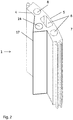
Fig. 2 shows a segment of the invention with a triangular baffle on the side facing inwards. -
Fig. 3 shows hollow profile segments (modules) forming a rigid cylindrical vessel side wall comprising heat exchange (HX) functionality. -
Fig. 4 shows the side wall ofFig. 3 with additional internal and external covers. -
Fig. 5 shows a) an alternative hollow profile segment and b) a rigid cylindrical vessel side wall made up of these segments. -
Fig. 6 shows cylindrical support vessels with axially aligned hollow profile segments that are connected to a top and bottom fluid manifold and to a bottom wall. a) parallel connection of heat exchange channels, b) serial connection of heat exchange channels, c) parallel connection with an intermediate manifold. -
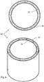
Fig. 7 shows extruded, ring shaped, elements stacked on top of each other to build a side wall for a cylindrical vessel. Rectangular or other geometries could be made accordingly. The fluid flow inside the elements can be mangaged both axially and laterally depending on the module configuration and the sealing and intermediate plates that could be stacked in between the extruded modules. -
Fig. 8 shows a cylindrical vessel with the side wall ofFig 7 and top and bottom manifolds and a bottom wall. -
Fig. 9 shows a bioreactor/mixer of the invention, with a flexible bag mounted in a support vessel. -
Fig. 10 shows a hollow profile segment (module) of the invention with an additional insulation channel. -
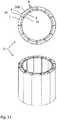
Fig. 11 shows a side wall of the invention with additional insulation channels in the hollow profile segments (modules). -
Fig. 12 shows different varieties (cross sections) of locking/coupling elements for segments of the invention. a) Protruding male element and recessed female element, b) Protruding male and female elements, c) Recessed female elements on segments and male elements on separate coupling profile, d) Genderless elements. - To more clearly and concisely describe and point out the subject matter of the claimed invention, the following definitions are provided for specific terms that are used in the following description and the claims appended hereto.
- The singular forms "a" "an" and "the" include plural referents unless the context clearly dictates otherwise. Approximating language, as used herein throughout the specification and claims, may be applied to modify any quantitative representation that could permissibly vary without resulting in a change in the basic function to which it is related. Accordingly, a value modified by a term such as "about" is not to be limited to the precise value specified. Unless otherwise indicated, all numbers expressing quantities of ingredients, properties such as molecular weight, reaction conditions, so forth used in the specification and claims are to be understood as being modified in all instances by the term "about." Accordingly, unless indicated to the contrary, the numerical parameters set forth in the following specification and attached claims are approximations that may vary depending upon the desired properties sought to be obtained by the embodiments of the present invention. At the very least each numerical parameter should at least be construed in light of the number of reported significant digits and by applying ordinary rounding techniques.
- As used herein to describe the present invention, directional terms such as "up", down", "top", "bottom", "vertical", "horizontal", as well as any other directional terms, refer to those directions of a bioreactor or mixer as used in the normal operational position.
- In one aspect, illustrated by
Figs. 1-4 , the present invention discloses an elongated hollowprofile wall segment 1 for a bioreactor ormixer support vessel 2;2a;2b. The wall segment comprises abase profile 3 with two parallelwide sides narrow sides heat exchange channel 8 that extends in a longitudinal direction of the base profile through aninterior space 9 in the base profile. The length ratio W/N of the wide sides to the narrow sides may e.g. be at least about 5, such as at least about 10, and/or the ratio of the segment length L to the wide side length W may e.g. be at least about 5, such as at least about 10. The base profile may have a substantially constant cross section geometry along alongitudinal axis 13, e.g. over at least 80% or at least 90% of the length of the profile or over the entire length of the profile. The wall segment is further adapted to be joined with similar wall segments to form aside wall 12 of a bioreactor ormixer support vessel 2;2a;2b and each narrow side comprises at least onecoupling member narrow side 6 may e.g. comprise amale coupling member 10 and a secondnarrow side 7 may comprise afemale coupling member 11;11a. The coupling members may e.g. comprise a recess, a track and/or a protrusion. If both coupling members are protruding from the narrow side (as inFigs 1 and12 b ), the joints may have some angular flexibility, which facilitates the joining. In this case it may be desirable to apply seal strips (not shown) over the joint to provide a smooth surface. If one coupling member is protruding and the other recessed in the narrow side (as inFigs. 3 and12 a ), a less flexible joint will be formed and seal strips may not be needed, particularly if the two narrow sides are in abutment with each other. This will also be the case for the embodiments shown inFig. 12 c) , where both segments have recessedfemale coupling elements 11a joined together by aseparate coupling profile 151 with twomale coupling elements 10a arranged to engageelements 11a by longitudinally sliding themale coupling elements 10a into thefemale coupling elements 11a. Alternatively, the two narrow sides may each comprise a genderless orhermaphroditic coupling member 150. The wall segment may be generally shaped as a sector of a circular tubular cylinder (i.e. with a cross section corresponding to a circular arc, with the segment having aconcave side 4 and a convex side 5), which allows for assembly of a circularcylindrical side wall 12;112 with theconcave sides 4 forming the inside 18 of the wall and theconvex sides 5 forming the outside 19 of the wall. Alternatively, the wall segment may have a generally rectangular shape, with straight sides. This allows for assembly of vessels of polygonal prism shape, such as a right polygonal prism. With a large number of rectangular wall elements, e.g. eight or higher, such a polygonal prism shape may approximate a circular cylindrical shape. In this case, vessel walls of different diameters may be assembled using a single type of wall segment. - In some embodiments, the hollow profile wall segment is an extruded profile, such as an extruded metal profile or an extruded plastic profile. Aluminium and aluminium alloys are commonly used in extruded profiles and the hollow profile wall segment can suitably be an extruded aluminium or aluminium alloy profile. Alternatively, the hollow profile wall segment may be manufactured from sheet metal, such as stainless steel sheet, e.g. by roll forming and (automated) welding. Metals, such as aluminium or aluminium alloys, have generally high thermal conductivities which is beneficial for the heat transfer efficiency.
- In certain embodiments, the at least one
heat exchange channel 8 contains one or more internal baffle elements (not shown). These promote turbulence and thereby achieve good heat transfer from the HX flow path. The baffle elements can e.g. be tortuous inserts acting as static mixer elements, e.g. inserts having a helical structure. Examples of such tortuous inserts are shown in e.g.US3286992 andUS3635444 . The baffle elements can however also be bulk fillers (particles), elongated structures, Raschig rings etc. - In some embodiments, illustrated by
Fig. 2 , one of thewide sides 4 comprises abaffle 17 protruding from the wide side 4 (the concave side if the segment is arc-formed). The baffle may e.g. have a triangular cross section. The baffle can also comprise a longitudinal baffleheat exchange channel 14, or aheat exchange channel 8 may also extend through the baffle as well as through the main body of the segment. This provides good heat exchange also via the baffle. - In certain embodiments, illustrated by
Figs. 10 and11 , the hollowwall profile segment 1 comprises one or moreadditional insulation channels 308. The insulation channel(s) can suitably be located adjacent to one 5 of the wide sides, such as theconvex side 5 if the segment has a circular arc cross section. The insulation channel(s) can then be located adjacent the outside 19 of a side wall composed of a plurality of profile segments, while the heat exchange channel(s) 8 for heat exchange fluid can be located near the inside 18 of the wall. This arrangement provides good temperature control and good external insulation. The insulation channel(s) may be filled with a thermal insulation material, such as e.g. a foam (e.g. polyurethane foam) or a fibrous material (e.g. glass wool or mineral wool). The profile segment may have a single insulation channel as shown inFig. 10 , but it may also have a plurality of insulation channels, suitably distributed along the (outer)wide side 5. The latter arrangement may provide higher mechanical stability due to the presence of internal walls between the insulation channels. - In a second aspect, illustrated by
Figs.3-6 , the invention discloses aside wall 12;112 of a bioreactor ormixer support vessel 2;2a;2b;102, which comprises a plurality of laterally joined hollowprofile wall segments 1;101. The segments, e.g. each segment, comprises abase profile 3;103 with two parallelwide sides narrow sides heat exchange channel 8;108 that extends in a longitudinal direction of the base profile through aninterior space 9;109 in the base profile. As above, the length ratio W/N of the wide sides to the narrow sides may e.g. be at least about 5, such as at least about 10, and/or the ratio of the segment length L to the wide side length W may e.g. be at least about 5, such as at least about 10. The base profile may also have a substantially constant cross section geometry along alongitudinal axis 13, e.g. over at least 80% or at least 90% of the length of the profile or over the entire length of the profile. The wall segments are joined side by side to form the side wall, e.g. via the coupling members. The joints can suitably be capable of withstanding the hydrostatic pressure from a liquid-filled flexible bag on the inside of the side wall. The wall segments can be as discussed in the embodiments above but they can also have other types of geometries. For example, they can betubes 103 with rectangular or arc-shaped cross section, a hollow interior (heat exchange channel) 108 and a tube wall composed of two parallelwide sides narrow sides tubes 103 may be joined side by side, e.g. by welding or soldering the respective narrow sides to each other. The side wall can be cylindrical, e.g. circular cylindrical (i.e. with an essentially circular cross section), or alternatively it can have a polygonal prism shape (i.e. having a polygonal cross section). It can further comprise anexternal cover 15, which may e.g. comprise a thermal insulation layer. Alternatively, or additionally, the side wall can also comprise aninternal cover 16, comprising e.g. a sheet-formed material such as a metal sheet, e.g. of stainless steel, or a plastic sheet. If a metal sheet comprising a different metal than the wall segments is used, a non-metallic protective layer or extra sheet may be provided to prevent the formation of galvanic elements. The internal cover can provide a smooth surface for contacting a flexible bag and it may also provide corrosion protection for the wall segments in case of bag leakage. In addition to, or as an alternative to the internal cover, the side wall may comprise a plurality of internal seal strips covering the coupling members to provide a smooth surface. It is also possible to apply one or more support rings (hoops) on the outside 19 or theexternal cover 15, to provide additional support against internal pressures. - In some embodiments, the side wall comprises a plurality of hollow profile wall segments each having a
baffle 17 protruding from awide side 4 on an inside 18 of the side wall and a plurality of hollow profile wall segments without baffles. The baffled segments can suitably be interspersed with non-baffle segments in such a way that the baffles are evenly distributed along the inside of the side wall. The side wall may e.g. comprise 2, 3, 4, 5 or 6 baffles. As discussed above, the baffles may contribute to the heat exchange via baffleheat exchange channels 14 orheat exchange channels 8 extending through the baffles. - In a third aspect, illustrated by
Figs.6 a) - c) , the invention discloses a bioreactor ormixer support vessel 2;2a;2b;102, comprising theside wall 12;112 as discussed in the embodiments above. The inner volume of the vessel may e.g. be at least 25 1, such as 25-2000 1, 50-2000 1 or 50-1000 1. An advantageous concept to manage the distribution of HX fluid over the individual segments is to build a barrel like construction (for the example a cylindrical vessel) and to connect the hollow segments at top and bottom to a circular or annular structure that provides mechanical support and fixation, liquid connections and the fluid distribution features desired. The support vessel comprises abottom wall 20 and top 21 and bottom 22 distribution manifolds, which may be annular, where the manifolds fluidically connect a plurality of theheat exchange channels 8 with aninlet 23 and anoutlet 24. Themanifolds inlet 23 oroutlet 24 fluidically connected to a plurality of heat exchangechannel connector ports 25 in register with theheat exchange channels 8. This arrangement provides a parallel coupling of the heat exchange channels such that heat exchange fluid can pass from the inlet to the outlet via a parallel set of heat exchange channels. Alternatively, the top and bottom distribution manifolds may comprise aninlet 23 fluidically connected to a first heat exchangechannel connector port 27a in register with a firstheat exchange channel 8a and a plurality of heat exchangechannel interconnector conduits 26, each of which is fluidically connected with two adjacentheat exchange channels 8 via heat exchangechannel interconnector ports 27 in register with said two adjacent heat exchange channels. A lastheat exchange channel 8b may then be fluidically connected via a last heat exchangechannel connector port 27b to anoutlet 24. This allows serial coupling of the heat exchange channels, such that the heat exchange fluid passes from the inlet through one heat exchange channel after another before reaching the outlet. In addition to the top and bottom manifolds, thesupport vessel 2b may also comprise one or morefurther manifolds 28, as illustrated byFig. 6 c) , where athird manifold 28 distributes heat exchange fluid frominlet 23 in both upwards and downwards directions via theheat exchange channels 8 to theoutlets 24. It is also possible to arrange fluidic connection between heat exchange channels by lateral ports (not shown) in the wall segments. In this case, at least two adjacent hollow profile wall segments comprise lateral ports, fluidically connecting theheat exchange channels 8 of the segments with each other. This could for example be achieved by creating an opening perpendicular to the direction of extrusion (by drilling or cutting) and fitting a sealing to this opening. Multiple segments could then be joined through such adjacent openings and sealings, the segments could be clamped against each other like the staves of a barrel. - In a fourth aspect, illustrated by
Fig. 9 , the invention discloses a bioreactor or mixer comprising aflexible bag 30 mounted in thesupport vessel 2 as discussed in the embodiments above. The flexible bag may e.g. be manufactured from a plastic laminate and may e.g. be loaded into the vessel from the top of the vessel. In the interior volume of thebag 33, cells can be cultivated or process liquids, e.g. buffers can be mixed. Through one ormore ports 34 in the bag, fluids can be added and removed as needed in the process. The bag may also comprise a magnetically drivenimpeller 31 for agitation, which may be driven by amagnetic drive unit 32 in or adjacent to the support vessel. The flexible bag may be supplied pre-sterilized, e.g. by gamma irradiation and may be used a single-use item, obviating the need for cleaning and cleaning validation of reusable vessels. During operation of the bioreactor or mixer,inlet 23 andoutlet 24 are suitably fluidically connected to a supply of HX fluid, such that HX fluid of suitable temperature is circulated through themanifolds heat exchange channels - In a fifth aspect, illustrated by
Figs. 7-8 , the invention discloses a hollowprofile wall section 201 for a cylindrical bioreactor ormixer support vessel 202 side wall, which comprises a basetubular section 203 with aninner surface 204, anouter surface 205 and a plurality ofheat exchange channels 208 extending in an axial direction through the base tubular section, wherein the hollow profile wall section is arranged to be stacked with similar hollow profile wall sections. The tubular sections could be annular, but they could also cover a larger or substantially the complete cylindrical surface to provide also a bottom structure of a vessel, for example. The tubular sections may be manufactured e.g. by extrusion, such as by extrusion of aluminium or an aluminium alloy. - In a sixth aspect, illustrated by
Figs. 7-8 , the invention discloses acylindrical side wall 202 of a bioreactor or mixer support vessel, comprising a plurality of stacked hollow profile wall sections as discussed in the embodiments above, wherein the heat exchange channels of the stacked sections are in register with each other. - In a seventh aspect, illustrated by
Fig. 8 , the invention discloses a bioreactor or mixer support vessel comprising acylindrical side wall 202 as discussed in the embodiments above, abottom wall 220 and top 221 and bottom 222 distribution manifolds, fluidically connecting a plurality of the heat exchange channels with aninlet 223 and anoutlet 224. AlthoughFig. 8 shows a parallel flow arrangement, it is equally possible to obtain serial flow by an arrangement analogous toFig. 6 b) . Further, a flexible bag may be mounted in the support vessel as illustrated inFig. 9 , to be used as a bioreactor or mixer as discussed above for the vessels having side walls made up of segments joined side by side. - In an eighth aspect, the invention discloses a method of cultivating cells in the bioreactors disclosed above. The method comprises providing a bioreactor with a flexible bag as discussed above. The flexible bag can suitably be supplied pre-sterilized. The method further comprises adding cells and culture medium to the flexible bag, suitably under aseptic conditions and cultivating said cells in the flexible bag. Cultivation of said cells is done suitably under agitation with addition and removal of gases (e.g. air and carbon dioxide) and under thermostatic conditions.
Claims (16)
- A hollow profile wall segment (1) for a bioreactor or mixer support vessel (2;2a;2b), comprising an extruded aluminium or aluminium alloy base profile (3) with two parallel wide sides (4,5), two narrow sides (6,7) and at least one heat exchange channel (8) extending in a longitudinal direction of said base profile through an interior space (9) in said base profile, wherein said hollow profile wall segment is adapted to be joined with similar hollow profile wall segments to form a side wall (12) of a bioreactor or mixer support vessel (2) and wherein each narrow side comprises at least one coupling member (10,11;11a;150) capable of securing said hollow profile wall segment side by side with similar hollow profile wall segments.
- The hollow profile wall segment of claim 1, wherein said at least one heat exchange channel contains one or more internal baffle elements.
- The hollow profile wall segment of any preceding claim, wherein a first narrow side (6) comprises a male coupling member (10) and a second narrow side (7) comprises a female coupling member (11), and/or wherein said coupling member comprises a recess, a track or a protrusion.
- The hollow profile wall segment of any preceding claim, wherein one of said wide sides (4) comprises a baffle (17) protruding from said wide side (4) wherein optionally said baffle has a triangular cross section.
- The hollow profile wall segment of any preceding claim, generally shaped as a sector of a circular tubular cylinder, or which is generally rectangular.
- The hollow profile wall segment of any preceding claim, further comprising one or more insulation channels (308), optionally comprising a thermal insulation material in said one or more insulation channels.
- A side wall (12;112) of a bioreactor or mixer support vessel (2;2a;2b;102), comprising a plurality of hollow profile wall segments (1;101) as defined in any preceding claim, wherein said plurality of hollow profile wall segments (1;101) are joined side by side.
- The side wall of claim 7, further comprising:a) an external cover (15);b) an internal cover (16); and/orc) a plurality of internal seal strips covering said coupling members.
- The side wall of claim 7 or 8, comprising a plurality of hollow profile wall segments each having a baffle protruding from a wide side (4) on an inside (17) of said cylindrical wall and a plurality of hollow profile wall segments without baffles.
- A bioreactor or mixer support vessel (2;2a;2b) comprising the side wall of any one of claims 7-9, a bottom wall (20) and top (21) and bottom (22) distribution manifolds, fluidically connecting a plurality of said heat exchange channels with an inlet (23) and at least one outlet (24), wherein optionally said top and bottom distribution manifolds are annular.
- The support vessel of claim 10, wherein:a) said top and bottom distribution manifolds comprise an inlet or outlet fluidically connected to a first heat exchange channel connector port in register with a first heat exchange channel (8a) and a plurality of heat exchange channel interconnector conduits (26), each fluidically connected with two adjacent heat exchange channels (8) via heat exchange channel interconnector ports (27);b) the support vessel further comprises a third distribution manifold (28), fluidically connecting a plurality of said heat exchange channels (8) with an inlet (23) or an outlet (24); and/orc) at least two adjacent hollow profile wall segments comprise lateral ports, fluidically connecting the heat exchange channels (8) of said segments with each other.
- A hollow profile wall section (201) for a cylindrical bioreactor or mixer support vessel, comprising a base tubular section (203) with an inner surface (204), an outer surface (205) and a plurality of heat exchange channels (208) extending in an axial direction through said base tubular section, wherein said hollow profile wall section is arranged to be stacked with similar hollow profile wall sections, wherein said base tubular section is an extruded aluminium or aluminium alloy section.
- A cylindrical side wall (202) of a bioreactor or mixer support vessel, comprising a plurality of stacked hollow profile wall sections according to claim 12, wherein the heat exchange channels of the stacked sections are in register with each other.
- A bioreactor or mixer support vessel comprising the cylindrical side wall (202) of claim 13, a bottom wall (220) and top (221) and bottom (222) distribution manifolds, fluidically connecting a plurality of said heat exchange channels (208) with an inlet (223) and an outlet (224).
- A bioreactor or mixer comprising the support vessel of any one of claims 10, 11 and 14 and a flexible bag (30) mounted in said support vessel.
- A method of cell cultivation, comprising the steps of:a) providing the bioreactor of claim 15;b) adding cells and culture medium to said flexible bag; andc) cultivating cells in said flexible bag.
Applications Claiming Priority (2)
| Application Number | Priority Date | Filing Date | Title |
|---|---|---|---|
| US201662336301P | 2016-05-13 | 2016-05-13 | |
| PCT/EP2017/061276 WO2017194652A1 (en) | 2016-05-13 | 2017-05-11 | Support vessels for single use bioreactors and mixers |
Publications (2)
| Publication Number | Publication Date |
|---|---|
| EP3455338A1 EP3455338A1 (en) | 2019-03-20 |
| EP3455338B1 true EP3455338B1 (en) | 2021-09-22 |
Family
ID=58699149
Family Applications (1)
| Application Number | Title | Priority Date | Filing Date |
|---|---|---|---|
| EP17722786.5A Active EP3455338B1 (en) | 2016-05-13 | 2017-05-11 | Support vessels for single use bioreactors and mixers |
Country Status (4)
| Country | Link |
|---|---|
| US (1) | US12084645B2 (en) |
| EP (1) | EP3455338B1 (en) |
| CN (1) | CN109072160B (en) |
| WO (1) | WO2017194652A1 (en) |
Families Citing this family (4)
| Publication number | Priority date | Publication date | Assignee | Title |
|---|---|---|---|---|
| WO2020260092A1 (en) * | 2019-06-24 | 2020-12-30 | Global Life Sciences Solutions Usa Llc | Bioreactor support system |
| EP3926036A1 (en) * | 2020-06-15 | 2021-12-22 | ESTR Biosystems GmbH | Tank for a bio-pharma process |
| JP7801309B2 (en) * | 2021-03-26 | 2026-01-16 | テルモ株式会社 | Cell Culture Systems |
| EP4660291A1 (en) * | 2024-06-07 | 2025-12-10 | Sartorius Stedim Biotech GmbH | Bioreactor and bioreactor vessel |
Family Cites Families (14)
| Publication number | Priority date | Publication date | Assignee | Title |
|---|---|---|---|---|
| BE754657Q (en) | 1965-11-29 | 1971-01-18 | Kenics Corp | MIXER APPLIANCE |
| US3635444A (en) | 1970-09-08 | 1972-01-18 | Amvit | Static mixer |
| US4282861A (en) * | 1977-06-28 | 1981-08-11 | Roark Charles F | Water heating system using solar energy |
| US4197689A (en) * | 1978-01-13 | 1980-04-15 | Demuth Steel Products Company | Bulk storage vessels |
| US5668922A (en) * | 1995-11-16 | 1997-09-16 | Rheem Manufacturing Company | Water heater having molded plastic storage tank and associated fabrication methods |
| CN1185554A (en) | 1996-12-20 | 1998-06-24 | 日野自动车工业株式会社 | Sealing washer |
| CN2612674Y (en) | 2003-04-18 | 2004-04-21 | 杨洪举 | Combined glass fibre reinforced plastic methane tank |
| US7870891B2 (en) * | 2004-05-29 | 2011-01-18 | Kilr-Chilr, Llc | Systems, devices and methods for regulating temperatures of tanks, containers and contents therein |
| US9534196B2 (en) * | 2009-03-25 | 2017-01-03 | Ge Healthcare Bio-Sciences Corp. | Temperature controlled support surfaces for single use flexible wall systems |
| US9340763B2 (en) * | 2008-03-25 | 2016-05-17 | Ge Healthcare Bio-Sciences Corp. | Temperature controlling surfaces and support structures |
| CN202089981U (en) | 2011-06-03 | 2011-12-28 | 甘肃宏鑫农业科技有限公司 | Waste agricultural film regeneration leakage-proof thermal insulation type methane tank |
| US9441365B2 (en) * | 2011-11-24 | 2016-09-13 | Cfs Concrete Forming Systems Inc. | Stay-in-place formwork with anti-deformation panels |
| CN104168993B (en) | 2012-03-16 | 2016-07-06 | 通用电气健康护理生物科学股份公司 | Hybrid system |
| WO2014089000A2 (en) | 2012-12-03 | 2014-06-12 | Ge Healthcare Bio-Sciences Corp. | Temperature controlling surfaces and support structures |
-
2017
- 2017-05-11 CN CN201780029291.9A patent/CN109072160B/en active Active
- 2017-05-11 WO PCT/EP2017/061276 patent/WO2017194652A1/en not_active Ceased
- 2017-05-11 EP EP17722786.5A patent/EP3455338B1/en active Active
- 2017-05-11 US US16/301,150 patent/US12084645B2/en active Active
Also Published As
| Publication number | Publication date |
|---|---|
| WO2017194652A1 (en) | 2017-11-16 |
| EP3455338A1 (en) | 2019-03-20 |
| CN109072160A (en) | 2018-12-21 |
| CN109072160B (en) | 2022-03-01 |
| US20190194589A1 (en) | 2019-06-27 |
| US12084645B2 (en) | 2024-09-10 |
Similar Documents
| Publication | Publication Date | Title |
|---|---|---|
| US12084645B2 (en) | Support vessels for single use bioreactors and mixers | |
| US12454671B2 (en) | Heat transfer baffle system and uses thereof | |
| US20230294054A1 (en) | Methods for operating a bioreactor with impeller assembly and related bioreactors | |
| JP5583010B2 (en) | Heat exchanger | |
| EP2594884B1 (en) | Plate heat exchanger and method for manufacturing of a plate heat exchanger | |
| EP2853584B1 (en) | Single-use bioreactor with baffles and a process for manufacturing and operating the same | |
| EP3616785B1 (en) | Baffling tube box, continuous flow reactor, continuous flow reaction system and control system | |
| US5586599A (en) | Heat exchanger | |
| JP2001525532A (en) | Enamelled almost flat metal heat exchanger | |
| CN111770790A (en) | Reactor system | |
| CN104903674A (en) | Temperature Control Surfaces and Support Structures | |
| EP2797682B1 (en) | System for controlling the temperature of a bioreactor | |
| JP5004444B2 (en) | Microreactor | |
| AU2022330672B2 (en) | Hollow-fiber membrane module unit | |
| CN211365716U (en) | Novel glass fiber reinforced plastic storage tank | |
| EP4636068A1 (en) | Single-use closed bioreactor for culturing, fermenting or processing a biomass | |
| CN220670266U (en) | Sanitary-grade high-efficiency double-tube-plate heat exchanger | |
| CN219914084U (en) | But pull heat exchanger | |
| US20240075449A1 (en) | Polymerization vessel and method for manufacturing the same | |
| WO2025219543A1 (en) | Single-use closed bioreactor for culturing, fermenting or processing a biomass | |
| JP2018017405A (en) | Heat exchanger and cultivation system |
Legal Events
| Date | Code | Title | Description |
|---|---|---|---|
| STAA | Information on the status of an ep patent application or granted ep patent |
Free format text: STATUS: UNKNOWN |
|
| STAA | Information on the status of an ep patent application or granted ep patent |
Free format text: STATUS: THE INTERNATIONAL PUBLICATION HAS BEEN MADE |
|
| PUAI | Public reference made under article 153(3) epc to a published international application that has entered the european phase |
Free format text: ORIGINAL CODE: 0009012 |
|
| STAA | Information on the status of an ep patent application or granted ep patent |
Free format text: STATUS: REQUEST FOR EXAMINATION WAS MADE |
|
| 17P | Request for examination filed |
Effective date: 20181106 |
|
| AK | Designated contracting states |
Kind code of ref document: A1 Designated state(s): AL AT BE BG CH CY CZ DE DK EE ES FI FR GB GR HR HU IE IS IT LI LT LU LV MC MK MT NL NO PL PT RO RS SE SI SK SM TR |
|
| AX | Request for extension of the european patent |
Extension state: BA ME |
|
| STAA | Information on the status of an ep patent application or granted ep patent |
Free format text: STATUS: EXAMINATION IS IN PROGRESS |
|
| DAV | Request for validation of the european patent (deleted) | ||
| DAX | Request for extension of the european patent (deleted) | ||
| 17Q | First examination report despatched |
Effective date: 20190820 |
|
| RAP1 | Party data changed (applicant data changed or rights of an application transferred) |
Owner name: CYTIVA SWEDEN AB |
|
| GRAP | Despatch of communication of intention to grant a patent |
Free format text: ORIGINAL CODE: EPIDOSNIGR1 |
|
| STAA | Information on the status of an ep patent application or granted ep patent |
Free format text: STATUS: GRANT OF PATENT IS INTENDED |
|
| INTG | Intention to grant announced |
Effective date: 20210412 |
|
| GRAS | Grant fee paid |
Free format text: ORIGINAL CODE: EPIDOSNIGR3 |
|
| GRAA | (expected) grant |
Free format text: ORIGINAL CODE: 0009210 |
|
| STAA | Information on the status of an ep patent application or granted ep patent |
Free format text: STATUS: THE PATENT HAS BEEN GRANTED |
|
| AK | Designated contracting states |
Kind code of ref document: B1 Designated state(s): AL AT BE BG CH CY CZ DE DK EE ES FI FR GB GR HR HU IE IS IT LI LT LU LV MC MK MT NL NO PL PT RO RS SE SI SK SM TR |
|
| REG | Reference to a national code |
Ref country code: GB Ref legal event code: FG4D |
|
| REG | Reference to a national code |
Ref country code: IE Ref legal event code: FG4D |
|
| REG | Reference to a national code |
Ref country code: DE Ref legal event code: R096 Ref document number: 602017046362 Country of ref document: DE |
|
| REG | Reference to a national code |
Ref country code: CH Ref legal event code: EP Ref country code: AT Ref legal event code: REF Ref document number: 1432348 Country of ref document: AT Kind code of ref document: T Effective date: 20211015 |
|
| REG | Reference to a national code |
Ref country code: LT Ref legal event code: MG9D |
|
| REG | Reference to a national code |
Ref country code: NL Ref legal event code: MP Effective date: 20210922 |
|
| PG25 | Lapsed in a contracting state [announced via postgrant information from national office to epo] |
Ref country code: HR Free format text: LAPSE BECAUSE OF FAILURE TO SUBMIT A TRANSLATION OF THE DESCRIPTION OR TO PAY THE FEE WITHIN THE PRESCRIBED TIME-LIMIT Effective date: 20210922 Ref country code: SE Free format text: LAPSE BECAUSE OF FAILURE TO SUBMIT A TRANSLATION OF THE DESCRIPTION OR TO PAY THE FEE WITHIN THE PRESCRIBED TIME-LIMIT Effective date: 20210922 Ref country code: RS Free format text: LAPSE BECAUSE OF FAILURE TO SUBMIT A TRANSLATION OF THE DESCRIPTION OR TO PAY THE FEE WITHIN THE PRESCRIBED TIME-LIMIT Effective date: 20210922 Ref country code: NO Free format text: LAPSE BECAUSE OF FAILURE TO SUBMIT A TRANSLATION OF THE DESCRIPTION OR TO PAY THE FEE WITHIN THE PRESCRIBED TIME-LIMIT Effective date: 20211222 Ref country code: FI Free format text: LAPSE BECAUSE OF FAILURE TO SUBMIT A TRANSLATION OF THE DESCRIPTION OR TO PAY THE FEE WITHIN THE PRESCRIBED TIME-LIMIT Effective date: 20210922 Ref country code: BG Free format text: LAPSE BECAUSE OF FAILURE TO SUBMIT A TRANSLATION OF THE DESCRIPTION OR TO PAY THE FEE WITHIN THE PRESCRIBED TIME-LIMIT Effective date: 20211222 Ref country code: LT Free format text: LAPSE BECAUSE OF FAILURE TO SUBMIT A TRANSLATION OF THE DESCRIPTION OR TO PAY THE FEE WITHIN THE PRESCRIBED TIME-LIMIT Effective date: 20210922 |
|
| REG | Reference to a national code |
Ref country code: AT Ref legal event code: MK05 Ref document number: 1432348 Country of ref document: AT Kind code of ref document: T Effective date: 20210922 |
|
| PG25 | Lapsed in a contracting state [announced via postgrant information from national office to epo] |
Ref country code: LV Free format text: LAPSE BECAUSE OF FAILURE TO SUBMIT A TRANSLATION OF THE DESCRIPTION OR TO PAY THE FEE WITHIN THE PRESCRIBED TIME-LIMIT Effective date: 20210922 Ref country code: GR Free format text: LAPSE BECAUSE OF FAILURE TO SUBMIT A TRANSLATION OF THE DESCRIPTION OR TO PAY THE FEE WITHIN THE PRESCRIBED TIME-LIMIT Effective date: 20211223 |
|
| PG25 | Lapsed in a contracting state [announced via postgrant information from national office to epo] |
Ref country code: AT Free format text: LAPSE BECAUSE OF FAILURE TO SUBMIT A TRANSLATION OF THE DESCRIPTION OR TO PAY THE FEE WITHIN THE PRESCRIBED TIME-LIMIT Effective date: 20210922 |
|
| PG25 | Lapsed in a contracting state [announced via postgrant information from national office to epo] |
Ref country code: IS Free format text: LAPSE BECAUSE OF FAILURE TO SUBMIT A TRANSLATION OF THE DESCRIPTION OR TO PAY THE FEE WITHIN THE PRESCRIBED TIME-LIMIT Effective date: 20220122 Ref country code: SK Free format text: LAPSE BECAUSE OF FAILURE TO SUBMIT A TRANSLATION OF THE DESCRIPTION OR TO PAY THE FEE WITHIN THE PRESCRIBED TIME-LIMIT Effective date: 20210922 Ref country code: RO Free format text: LAPSE BECAUSE OF FAILURE TO SUBMIT A TRANSLATION OF THE DESCRIPTION OR TO PAY THE FEE WITHIN THE PRESCRIBED TIME-LIMIT Effective date: 20210922 Ref country code: PT Free format text: LAPSE BECAUSE OF FAILURE TO SUBMIT A TRANSLATION OF THE DESCRIPTION OR TO PAY THE FEE WITHIN THE PRESCRIBED TIME-LIMIT Effective date: 20220124 Ref country code: PL Free format text: LAPSE BECAUSE OF FAILURE TO SUBMIT A TRANSLATION OF THE DESCRIPTION OR TO PAY THE FEE WITHIN THE PRESCRIBED TIME-LIMIT Effective date: 20210922 Ref country code: NL Free format text: LAPSE BECAUSE OF FAILURE TO SUBMIT A TRANSLATION OF THE DESCRIPTION OR TO PAY THE FEE WITHIN THE PRESCRIBED TIME-LIMIT Effective date: 20210922 Ref country code: ES Free format text: LAPSE BECAUSE OF FAILURE TO SUBMIT A TRANSLATION OF THE DESCRIPTION OR TO PAY THE FEE WITHIN THE PRESCRIBED TIME-LIMIT Effective date: 20210922 Ref country code: EE Free format text: LAPSE BECAUSE OF FAILURE TO SUBMIT A TRANSLATION OF THE DESCRIPTION OR TO PAY THE FEE WITHIN THE PRESCRIBED TIME-LIMIT Effective date: 20210922 Ref country code: CZ Free format text: LAPSE BECAUSE OF FAILURE TO SUBMIT A TRANSLATION OF THE DESCRIPTION OR TO PAY THE FEE WITHIN THE PRESCRIBED TIME-LIMIT Effective date: 20210922 Ref country code: AL Free format text: LAPSE BECAUSE OF FAILURE TO SUBMIT A TRANSLATION OF THE DESCRIPTION OR TO PAY THE FEE WITHIN THE PRESCRIBED TIME-LIMIT Effective date: 20210922 |
|
| REG | Reference to a national code |
Ref country code: DE Ref legal event code: R097 Ref document number: 602017046362 Country of ref document: DE |
|
| PG25 | Lapsed in a contracting state [announced via postgrant information from national office to epo] |
Ref country code: DK Free format text: LAPSE BECAUSE OF FAILURE TO SUBMIT A TRANSLATION OF THE DESCRIPTION OR TO PAY THE FEE WITHIN THE PRESCRIBED TIME-LIMIT Effective date: 20210922 |
|
| PLBE | No opposition filed within time limit |
Free format text: ORIGINAL CODE: 0009261 |
|
| STAA | Information on the status of an ep patent application or granted ep patent |
Free format text: STATUS: NO OPPOSITION FILED WITHIN TIME LIMIT |
|
| 26N | No opposition filed |
Effective date: 20220623 |
|
| PG25 | Lapsed in a contracting state [announced via postgrant information from national office to epo] |
Ref country code: SI Free format text: LAPSE BECAUSE OF FAILURE TO SUBMIT A TRANSLATION OF THE DESCRIPTION OR TO PAY THE FEE WITHIN THE PRESCRIBED TIME-LIMIT Effective date: 20210922 |
|
| REG | Reference to a national code |
Ref country code: CH Ref legal event code: PL |
|
| REG | Reference to a national code |
Ref country code: BE Ref legal event code: MM Effective date: 20220531 |
|
| PG25 | Lapsed in a contracting state [announced via postgrant information from national office to epo] |
Ref country code: MC Free format text: LAPSE BECAUSE OF FAILURE TO SUBMIT A TRANSLATION OF THE DESCRIPTION OR TO PAY THE FEE WITHIN THE PRESCRIBED TIME-LIMIT Effective date: 20210922 Ref country code: LU Free format text: LAPSE BECAUSE OF NON-PAYMENT OF DUE FEES Effective date: 20220511 Ref country code: LI Free format text: LAPSE BECAUSE OF NON-PAYMENT OF DUE FEES Effective date: 20220531 Ref country code: IT Free format text: LAPSE BECAUSE OF FAILURE TO SUBMIT A TRANSLATION OF THE DESCRIPTION OR TO PAY THE FEE WITHIN THE PRESCRIBED TIME-LIMIT Effective date: 20210922 Ref country code: CH Free format text: LAPSE BECAUSE OF NON-PAYMENT OF DUE FEES Effective date: 20220531 |
|
| PG25 | Lapsed in a contracting state [announced via postgrant information from national office to epo] |
Ref country code: IE Free format text: LAPSE BECAUSE OF NON-PAYMENT OF DUE FEES Effective date: 20220511 |
|
| PG25 | Lapsed in a contracting state [announced via postgrant information from national office to epo] |
Ref country code: BE Free format text: LAPSE BECAUSE OF NON-PAYMENT OF DUE FEES Effective date: 20220531 |
|
| P01 | Opt-out of the competence of the unified patent court (upc) registered |
Effective date: 20230526 |
|
| PG25 | Lapsed in a contracting state [announced via postgrant information from national office to epo] |
Ref country code: HU Free format text: LAPSE BECAUSE OF FAILURE TO SUBMIT A TRANSLATION OF THE DESCRIPTION OR TO PAY THE FEE WITHIN THE PRESCRIBED TIME-LIMIT; INVALID AB INITIO Effective date: 20170511 |
|
| PG25 | Lapsed in a contracting state [announced via postgrant information from national office to epo] |
Ref country code: SM Free format text: LAPSE BECAUSE OF FAILURE TO SUBMIT A TRANSLATION OF THE DESCRIPTION OR TO PAY THE FEE WITHIN THE PRESCRIBED TIME-LIMIT Effective date: 20210922 Ref country code: MK Free format text: LAPSE BECAUSE OF FAILURE TO SUBMIT A TRANSLATION OF THE DESCRIPTION OR TO PAY THE FEE WITHIN THE PRESCRIBED TIME-LIMIT Effective date: 20210922 Ref country code: CY Free format text: LAPSE BECAUSE OF FAILURE TO SUBMIT A TRANSLATION OF THE DESCRIPTION OR TO PAY THE FEE WITHIN THE PRESCRIBED TIME-LIMIT Effective date: 20210922 |
|
| PG25 | Lapsed in a contracting state [announced via postgrant information from national office to epo] |
Ref country code: TR Free format text: LAPSE BECAUSE OF FAILURE TO SUBMIT A TRANSLATION OF THE DESCRIPTION OR TO PAY THE FEE WITHIN THE PRESCRIBED TIME-LIMIT Effective date: 20210922 |
|
| PG25 | Lapsed in a contracting state [announced via postgrant information from national office to epo] |
Ref country code: MT Free format text: LAPSE BECAUSE OF FAILURE TO SUBMIT A TRANSLATION OF THE DESCRIPTION OR TO PAY THE FEE WITHIN THE PRESCRIBED TIME-LIMIT Effective date: 20210922 |
|
| PGFP | Annual fee paid to national office [announced via postgrant information from national office to epo] |
Ref country code: DE Payment date: 20250528 Year of fee payment: 9 |
|
| PGFP | Annual fee paid to national office [announced via postgrant information from national office to epo] |
Ref country code: FR Payment date: 20250526 Year of fee payment: 9 |
|
| PGFP | Annual fee paid to national office [announced via postgrant information from national office to epo] |
Ref country code: GB Payment date: 20260304 Year of fee payment: 10 |