EP3454554A1 - Method and device for evaluating quality of digital image - Google Patents
Method and device for evaluating quality of digital image Download PDFInfo
- Publication number
- EP3454554A1 EP3454554A1 EP17795493.0A EP17795493A EP3454554A1 EP 3454554 A1 EP3454554 A1 EP 3454554A1 EP 17795493 A EP17795493 A EP 17795493A EP 3454554 A1 EP3454554 A1 EP 3454554A1
- Authority
- EP
- European Patent Office
- Prior art keywords
- space
- evaluated
- pixel
- digital image
- pixel group
- Prior art date
- Legal status (The legal status is an assumption and is not a legal conclusion. Google has not performed a legal analysis and makes no representation as to the accuracy of the status listed.)
- Ceased
Links
Images

Classifications
-
- G—PHYSICS
- G06—COMPUTING OR CALCULATING; COUNTING
- G06T—IMAGE DATA PROCESSING OR GENERATION, IN GENERAL
- G06T3/00—Geometric image transformations in the plane of the image
- G06T3/02—Affine transformations
-
- H—ELECTRICITY
- H04—ELECTRIC COMMUNICATION TECHNIQUE
- H04N—PICTORIAL COMMUNICATION, e.g. TELEVISION
- H04N19/00—Methods or arrangements for coding, decoding, compressing or decompressing digital video signals
- H04N19/10—Methods or arrangements for coding, decoding, compressing or decompressing digital video signals using adaptive coding
- H04N19/134—Methods or arrangements for coding, decoding, compressing or decompressing digital video signals using adaptive coding characterised by the element, parameter or criterion affecting or controlling the adaptive coding
- H04N19/154—Measured or subjectively estimated visual quality after decoding, e.g. measurement of distortion
-
- G—PHYSICS
- G06—COMPUTING OR CALCULATING; COUNTING
- G06T—IMAGE DATA PROCESSING OR GENERATION, IN GENERAL
- G06T7/00—Image analysis
- G06T7/0002—Inspection of images, e.g. flaw detection
-
- H—ELECTRICITY
- H04—ELECTRIC COMMUNICATION TECHNIQUE
- H04N—PICTORIAL COMMUNICATION, e.g. TELEVISION
- H04N17/00—Diagnosis, testing or measuring for television systems or their details
- H04N17/004—Diagnosis, testing or measuring for television systems or their details for digital television systems
-
- H—ELECTRICITY
- H04—ELECTRIC COMMUNICATION TECHNIQUE
- H04N—PICTORIAL COMMUNICATION, e.g. TELEVISION
- H04N19/00—Methods or arrangements for coding, decoding, compressing or decompressing digital video signals
- H04N19/50—Methods or arrangements for coding, decoding, compressing or decompressing digital video signals using predictive coding
- H04N19/597—Methods or arrangements for coding, decoding, compressing or decompressing digital video signals using predictive coding specially adapted for multi-view video sequence encoding
-
- G—PHYSICS
- G06—COMPUTING OR CALCULATING; COUNTING
- G06T—IMAGE DATA PROCESSING OR GENERATION, IN GENERAL
- G06T2207/00—Indexing scheme for image analysis or image enhancement
- G06T2207/10—Image acquisition modality
- G06T2207/10016—Video; Image sequence
-
- G—PHYSICS
- G06—COMPUTING OR CALCULATING; COUNTING
- G06T—IMAGE DATA PROCESSING OR GENERATION, IN GENERAL
- G06T2207/00—Indexing scheme for image analysis or image enhancement
- G06T2207/30—Subject of image; Context of image processing
- G06T2207/30168—Image quality inspection
Definitions
- This patent belongs to the field of communication technology, and more specifically speaking, it is a method for evaluating the quality of a digital image in the case where the representation space of digital images is different from corresponding observation space.
- digital image signal is a two-dimensional signal arranged in space.
- a window is utilized to collect pixel samples in the spatial domain to form a digital image.
- the images collected at different times are arranged in chronological order to form a moving digital image sequence.
- An important purpose of digital images is to be used for watching, and the objective quality evaluation of digital images affects the loss of compression, transmission and other process of digital images.
- observation space The space of scene captured by camera is defined as observation space, which reflects the actual pictures captured by human eyes. But the space of observation space varies from its design to multi-camera system. Considering the convenience of signal processing, we usually project image expressed in the observation space to the representation space as the conversion to unify the signal format. Those images in the representation space are more convenient to be processed (the most common representation space is the two-dimensional plane).
- representation space is consistent with the observation space (the connection between the representation space and the presentation space can be established by affine transformation), meaning that the processing image is consistent with the observing image. Therefore, characteristics of the observation space need no extra processing when conventional digital images are processed.
- To evaluate the quality of a signal in the space to be evaluated we need to specify a standard reference space to indicate the best signal. Then signal quality, the distortion of signal in the space to be evaluated, can be evaluated by comparing the difference between the signal in the representation space and the reference space.
- the objective quality of the basic processing unit A 1 in the digital image can be evaluated by the most popular objective quality evaluation method.
- the objective quality (distortion)
- the difference function can be summing the absolute value of differences of each pixel belonging to A 1 and A o , or may be the mean squared error of A 1 and A o , or the peak signal-to-noise ratio of A 1 and A o .
- the difference function is not limited to those mentioned above.
- the digital image space we have observed is no longer limited to two-dimensional plane any more, Naked-eye 3D technology, panoramic digital image technology, 360-degree virtual reality technology and many other innovations have created various modes of presentation.
- high-dimensional signal will be converted to 2D plane through the projection transformation so that the signal can be processed in an easier way.
- video coding standard can only encode two-dimensional content for now.
- a common operation is that project high-dimensional space to a two-dimensional plane, and then encode the two-dimensional content.
- the patent proposes an evaluation scheme for digital image quality based on an observation space.
- the relationship between the representation space and the observation space of the digital image cannot be represented by affine transformation.
- the first technical solution of the present invention is to provide a digital image quality evaluation method for measuring the quality of a digital image in the space to be evaluated.
- This method comprising: summing the absolute value of the pixel values of the respective pixel group of the digital images in the space to be evaluated and the digital images in the reference space pixel by pixel to obtain the distortion values.
- the described pixel group comprises at least one of the following expressions:
- the described method to obtain the absolute value of the digital images comprises at least one of the following processing methods:
- the distortion values of the digital images in the space to be evaluated are processed according to the distribution of pixel groups in observation space.
- the method to process the distortion value of the digital images in the space to be evaluated according to the distribution of the pixel groups in observation space comprises at least one of the following processing methods:
- the method to locate the relevant area corresponding to the pixel group comprises at least one of the following methods:
- the quality of the digital images in the space to be evaluated is measured by using the distortion value of the pixel groups of the entire digital image to be evaluated after the processing.
- the second technical solution of the present invention is to provide a digital image quality evaluation apparatus for measuring the quality of a digital image in the space to be evaluated.
- This apparatus comprising: summing the absolute value of the pixel values of each pixel group of the digital image in the space to be evaluated and the digital image in the reference space pixel by pixel to obtain the distortion value.
- the described pixel group comprises at least one of the following expressions:
- the input of the distortion generation module is the reference spatial digital image and the space to be evaluated and the output is distortion corresponding to the pixel group in the space to be evaluated.
- the method to obtain the absolute value of the digital image comprises at least one of the following processing methods:
- a weighted distortion processing module processes the distortion value according to the distribution of the pixel group of the digital image in the space to be evaluated on the observation space, the input of which is the space to be evaluated and the output space is the corresponding weights of the pixel group in the space to be evaluated.
- the method to process the distortion value according to the distribution in the observation space of the pixel group of the digital image in the space to be evaluated comprises at least one of the following processing methods:
- the method to locate the correlation area corresponding to the pixel group comprises at least one of the following methods:
- the processed distortion corresponding to the pixel group of the digital image of the entire image to be evaluated and the corresponding weights of the digital image are utilized to evaluate the quality of the digital image to be evaluated
- the input of quality evaluation module is the corresponding weights of the pixel group and the distortion value corresponding to the pixel group in the space to be evaluated and output is the quality of the digital image in the observation space.
- the third technical solution of the present invention is to provide a digital image quality evaluation method for measuring the quality of a digital image in the space to be evaluated.
- This method comprising: obtaining the distortion values of each pixel group in the digital image by using the pixel values of the respective pixel groups of the digital images in the space to be evaluated and reference space.
- the method to obtain the distortion values of each pixel group in the digital image comprises at least one of the following processing methods:
- the distortion values of the pixel groups of the digital images in the space to be evaluated are processed according to the distribution in observation space.
- the method to process the distortion value of the pixel groups of the digital images in the space to be evaluated according to the distribution in observation space comprises at least one of the following processing methods:
- the method to locate the relevant area corresponding to the pixel group comprises at least one of the following methods:
- the quality of the digital images in the space to be evaluated is measured by using the distortion value of the pixel group of the entire digital image to be evaluated after the processing.
- the fourth technical solution of the present invention is to provide a digital image quality evaluation apparatus for measuring the quality of a digital image in the space to be evaluated.
- This apparatus comprising: the pixel values of each pixel group in the digital image to be evaluated is calculated pixel by pixel with the corresponding pixel values of the digital image in the reference space to obtain the distortion value, which is the distortion generation module; the input is the digital images in reference space and the space to be evaluated and the output is distortion values for the pixel group in the space to be evaluated.
- the method to obtain the distortion value of the digital image in distortion generation module comprises at least one of the following processing methods:
- a weighted distortion processing module processes the distortion value of the pixel group of the digital image in the space to be evaluated according to the distribution in the observation space, the input of which are the distribution of pixel group in the digital image to be evaluated and the observation space and the output is the corresponding weights of the pixel group in the space to be evaluated.
- the method to obtain the result of quality evaluation in quality evaluation module comprises at least one of the following processing methods:
- the method to locate the relevant area corresponding to the pixel group comprises at least one of the following methods:
- the processed distortion corresponding to the pixel group of the digital image of the entire image to be evaluated and the corresponding weights of the digital image are utilized to measure the quality of the digital image to be evaluated, input is the corresponding weights of the pixel group and the distortion value corresponding to the pixel group in the space to be evaluated and output is the quality of the digital image in the observation space.
- Benefit of this invention is that the distribution of the corresponding processing unit in the observation space is introduced the evaluation of digital images quality in the representation space compared with the conventional technique. Compared with the prior methods, the problem caused by selection of points in observation space uniformly is avoided (uniform sampling on the sphere is an extremely difficult problem), which is converted to the problem of the area of the processing unit. The area can be calculated offline or online. What's more, this kind of design reduces the error introduced by the conversion between representation spaces. For the case where the representation space of the reference digital image W rep and the representation space of the digital image to be evaluated W t can be linearly represented, no conversion is required.
- the processing units in the following embodiments may have different sizes and shapes, such as WxH rectangles, WxW squares, 1x1 single pixels, and other special shapes such as triangles, hexagons, etc.
- Each processing unit comprises only one image component (e.g., R or G or B, Y or U or V), and may comprise all components of one image. Last but not least, the processing unit here can not represent the entire image.
- observation space in the following embodiments are defined as a sphere. Followings are some typical mapping space.
- CMP cube map projection
- a cube having exterior contact with the sphere is utilized to describe the spherical scene.
- Points on the cube are defined as the intersection of cube plane and lines starting from the center of the sphere and terminating on the point of the sphere.
- the point on the cube can specify the unique corresponding point on the sphere.
- This CMP format is represented by cube space.
- the rectangular pyramid format in the following embodiments is defined as follows: a rectangular pyramid having exterior contact with the sphere is utilized to describe the spherical scene. Points on the rectangular pyramid are defined as the intersection of rectangular pyramid plane and lines starting from the center of the sphere and terminating on the point of the sphere. The point on the rectangular pyramid can specify the unique corresponding point on the sphere.
- This rectangular pyramid format is represented by rectangular pyramid space.
- N-face format in the following embodiments is defined as follows: a N-face having exterior contact with the sphere is utilized to describe the spherical scene. Points on the N-face are defined as the intersection of N-face plane and lines starting from the center of the sphere and terminating on the point of the sphere. The point on the N-face can specify the unique corresponding point on the sphere. This N-face format is represented by N-face space.
- difference function Diff ( A 1 , A 2 ) in embodiments is defined as followings: firstly, the precondition is that the representation space W 1 where A 1 belonging to must be linear to the representation space W 2 where A 2 belonging to and each pixel in A 1 must have unique corresponding pixel in A 2 .
- Difference function Diff ( A 1 , A 2 ) can be the sum of the absolute value of differences of each pixel belonging to A 1 and A 2 , or may be the mean squared error of A 1 and A 2 , or the peak signal-to-noise ratio of A 1 and A 2 .
- the difference function is not limited to those mentioned above.
- the first embodiment of the patent relates to a digital image quality evaluation method.
- the observation space W o to present observing digital images is a sphere.
- the representation space of digital images to be evaluated W t is equi rectangular projection (ERP) format.
- the representation space of reference digital images W rep is ERP format.
- the objective quality of digital images in the space to be evaluated is calculated as follows:
- the second embodiment of the patent relates to a digital image quality evaluation method.
- the observation space W o to present observing digital images is a sphere.
- the representation space of digital images to be evaluated W t is equi rectangular projection (ERP) format.
- the representation space of reference digital images W rep is ERP format.
- the objective quality of digital images in the space to be evaluated is calculated as follows:
- the third embodiment of the patent relates to a digital image quality evaluation method.
- the observation space W o to present observing digital images is a sphere.
- the representation space of digital images to be evaluated W t is equi rectangular projection (ERP) format.
- the representation space of reference digital images W rep is ERP format.
- the objective quality of digital images in the space to be evaluated is calculated as follows:
- the fourth embodiment of the patent relates to a digital image quality evaluation method.
- the observation space W o to present observing digital images is a sphere.
- the representation space of digital images to be evaluated W t is equi rectangular projection (ERP) format.
- the representation space of reference digital images W rep is ERP format.
- the objective quality of digital images in the space to be evaluated is calculated as follows:
- the fifth embodiment of the patent relates to a digital image quality evaluation method.
- the observation space W o to present observing digital images is a sphere.
- the representation space of digital images to be evaluated W t is equi rectangular projection (ERP) format.
- the representation space of reference digital images W rep is ERP format.
- the objective quality of digital images in the space to be evaluated is calculated as follows:
- the sixth embodiment of the patent relates to a digital image quality evaluation method.
- the observation space W o to present observing digital images is a sphere.
- the representation space of digital images to be evaluated W t is equi rectangular projection (ERP) format.
- the representation space of reference digital images W rep is ERP format.
- the objective quality of digital images in the space to be evaluated is calculated as follows:
- the seventh embodiment of the patent relates to a digital image quality evaluation method.
- the observation space W o to present observing digital images is a sphere.
- the representation space of digital images to be evaluated W t is equi rectangular projection (ERP) format.
- the representation space of reference digital images W rep is ERP format.
- the objective quality of digital images in the space to be evaluated is calculated as follows:
- the eighth embodiment of the patent relates to a digital image quality evaluation method.
- the observation space W o to present observing digital images is a sphere.
- the representation space of digital images to be evaluated W t is equi rectangular projection (ERP) format.
- the representation space of reference digital images W rep is ERP format.
- the objective quality of digital images in the space to be evaluated is calculated as follows:
- the ninth embodiment of the patent relates to a digital image quality evaluation method.
- the observation space W o to present observing digital images is a sphere.
- the representation space of digital images to be evaluated W t is equi rectangular projection (ERP) format.
- the representation space of reference digital images W rep is ERP format.
- the objective quality of digital images in the space to be evaluated is calculated as follows:
- the tenth embodiment of the patent relates to a digital image quality evaluation method.
- the observation space W o to present observing digital images is a sphere.
- the representation space of digital images to be evaluated W t is equi rectangular projection (ERP) format.
- the representation space of reference digital images W rep is ERP format.
- the objective quality of digital images in the space to be evaluated is calculated as follows:
- the eleventh embodiment of the patent relates to a digital image quality evaluation method.
- the observation space W o to present observing digital images is a sphere.
- the representation space of digital images to be evaluated W t is equi rectangular projection (ERP) format.
- the representation space of reference digital images W rep is ERP format.
- the objective quality of digital images in the space to be evaluated is calculated as follows:
- the twelfth embodiment of the patent relates to a digital image quality evaluation method.
- the observation space W o to present observing digital images is a sphere.
- the representation space of digital images to be evaluated W t is equi rectangular projection (ERP) format.
- the representation space of reference digital images W rep is ERP format.
- the objective quality of digital images in the space to be evaluated is calculated as follows:
- the thirteenth embodiment of the patent relates to a digital image quality evaluation method.
- the observation space W o to present observing digital images is a sphere.
- the representation space of digital images to be evaluated W t is cube map projection (CMP) format.
- the representation space of reference digital images W rep is CMP format.
- the objective quality of digital images in the space to be evaluated is calculated as follows:
- the fourteenth embodiment of the patent relates to a digital image quality evaluation method.
- the observation space W o to present observing digital images is a sphere.
- the representation space of digital images to be evaluated W t is cube map projection (CMP) format.
- the representation space of reference digital images W rep is CMP format.
- the objective quality of digital images in the space to be evaluated is calculated as follows:
- the fifteenth embodiment of the patent relates to a digital image quality evaluation method.
- the observation space W o to present observing digital images is a sphere.
- the representation space of digital images to be evaluated W t is cube map projection (CMP) format.
- the representation space of reference digital images W rep is CMP format.
- the objective quality of digital images in the space to be evaluated is calculated as follows:
- the sixteenth embodiment of the patent relates to a digital image quality evaluation method.
- the observation space W o to present observing digital images is a sphere.
- the representation space of digital images to be evaluated W t is cube map projection (CMP) format.
- the representation space of reference digital images W rep is CMP format.
- the objective quality of digital images in the space to be evaluated is calculated as follows:
- the seventeenth embodiment of the patent relates to a digital image quality evaluation method.
- the observation space W o to present observing digital images is a sphere.
- the representation space of digital images to be evaluated W t is cube map projection (CMP) format.
- the representation space of reference digital images W rep is CMP format.
- the objective quality of digital images in the space to be evaluated is calculated as follows:
- the eighteenth embodiment of the patent relates to a digital image quality evaluation method.
- the observation space W o to present observing digital images is a sphere.
- the representation space of digital images to be evaluated W t is cube map projection (CMP) format.
- the representation space of reference digital images W rep is CMP format.
- the objective quality of digital images in the space to be evaluated is calculated as follows:
- the nineteenth embodiment of the patent relates to a digital image quality evaluation method.
- the observation space W o to present observing digital images is a sphere.
- the representation space of digital images to be evaluated W t is cube map projection (CMP) format.
- the representation space of reference digital images W rep is CMP format.
- the objective quality of digital images in the space to be evaluated is calculated as follows:
- the twentieth embodiment of the patent relates to a digital image quality evaluation method.
- the observation space W o to present observing digital images is a sphere.
- the representation space of digital images to be evaluated W t is cube map projection (CMP) format.
- the representation space of reference digital images W rep is CMP format.
- the objective quality of digital images in the space to be evaluated is calculated as follows:
- the twenty-first embodiment of the patent relates to a digital image quality evaluation method.
- the observation space W o to present observing digital images is a sphere.
- the representation space of digital images to be evaluated W t is cube map projection (CMP) format.
- the representation space of reference digital images W rep is CMP format.
- the objective quality of digital images in the space to be evaluated is calculated as follows:
- the twenty-second embodiment of the patent relates to a digital image quality evaluation method.
- the observation space W o to present observing digital images is a sphere.
- the representation space of digital images to be evaluated W t is cube map projection (CMP) format.
- the representation space of reference digital images W rep is CMP format.
- the objective quality of digital images in the space to be evaluated is calculated as follows:
- the twenty-third embodiment of the patent relates to a digital image quality evaluation method.
- the observation space W o to present observing digital images is a sphere.
- the representation space of digital images to be evaluated W t is cube map projection (CMP) format.
- the representation space of reference digital images W rep is CMP format.
- the objective quality of digital images in the space to be evaluated is calculated as follows:
- the twenty-fourth embodiment of the patent relates to a digital image quality evaluation method.
- the observation space W o to present observing digital images is a sphere.
- the representation space of digital images to be evaluated W t is cube map projection (CMP) format.
- the representation space of reference digital images W rep is CMP format.
- the objective quality of digital images in the space to be evaluated is calculated as follows:
- the twenty-fifth embodiment of the patent relates to a digital image quality evaluation method.
- the observation space of digital images is W o .
- the representation space of digital images is W rep and the representation space of reference digital images is W rep .
- the combination of W t , W o and W rep can be (ERP, sphere, ERP), (CMP, sphere, ERP), (ERP, sphere, CMP), (CMP, sphere, CMP), (rectangular pyramid, sphere, ERP), (ERP, sphere, rectangular pyramid), (rectangular pyramid, sphere, rectangular pyramid), (N-face format, sphere, M-face format), (ERP, sphere, M-face format) and (M-face format, sphere, ERP). But combinations are not limited to the above examples.
- the objective quality of digital images in the space to be evaluated is calculated as follows:
- the twenty-sixth embodiment of the patent relates to a digital image quality evaluation method.
- the observation space of digital images is W o .
- the representation space of digital images is W rep and the representation space of reference digital images is W rep .
- the combination of W t , W o and W rep can be (ERP, sphere, ERP), (CMP, sphere, ERP), (ERP, sphere, CMP), (CMP, sphere, CMP), (rectangular pyramid, sphere, ERP), (ERP, sphere, rectangular pyramid), (rectangular pyramid, sphere, rectangular pyramid), (N-face format, sphere, M-face format), (ERP, sphere, M-face format) and (M-face format, sphere, ERP). But combinations are not limited to the above examples.
- the objective quality of digital images in the space to be evaluated is calculated as follows:
- the twenty-seventh embodiment of the patent relates to a digital image quality evaluation method.
- the observation space of digital images is W o .
- the representation space of digital images is W rep and the representation space of reference digital images is W rep .
- the combination of W t , W o and W rep can be (ERP, sphere, ERP), (CMP, sphere, ERP), (ERP, sphere, CMP), (CMP, sphere, CMP), (rectangular pyramid, sphere, ERP), (ERP, sphere, rectangular pyramid), (rectangular pyramid, sphere, rectangular pyramid), (N-face format, sphere, M-face format), (ERP, sphere, M-face format) and (M-face format, sphere, ERP). But combinations are not limited to the above examples.
- the objective quality of digital images in the space to be evaluated is calculated as follows:
- the twenty-eighth embodiment of the patent relates to a digital image quality evaluation method.
- the observation space of digital images is W o .
- the representation space of digital images is W t and the representation space of reference digital images is W rep .
- the combination of W t , W o and W rep can be (ERP, sphere, ERP), (CMP, sphere, ERP), (ERP, sphere, CMP), (CMP, sphere, CMP), (rectangular pyramid, sphere, ERP), (ERP, sphere, rectangular pyramid), (rectangular pyramid, sphere, rectangular pyramid), (N-face format, sphere, M-face format), (ERP, sphere, M-face format) and (M-face format, sphere, ERP). But combinations are not limited to the above examples.
- the objective quality of digital images in the space to be evaluated is calculated as follows:
- the twenty-ninth embodiment of the patent relates to a digital image quality evaluation method.
- the observation space of digital images is W o .
- the representation space of digital images is W t and the representation space of reference digital images is W rep .
- the combination of W t , W o and W rep can be (ERP, sphere, ERP), (CMP, sphere, ERP), (ERP, sphere, CMP), (CMP, sphere, CMP), (rectangular pyramid, sphere, ERP), (ERP, sphere, rectangular pyramid), (rectangular pyramid, sphere, rectangular pyramid), (N-face format, sphere, M-face format), (ERP, sphere, M-face format) and (M-face format, sphere, ERP). But combinations are not limited to the above examples.
- the objective quality of digital images in the space to be evaluated is calculated as follows:
- the thirtieth embodiment of the patent relates to a digital image quality evaluation method.
- the observation space of digital images is W o .
- the representation space of digital images is W t and the representation space of reference digital images is W rep .
- the combination of W t , W o and W rep can be (ERP, sphere, ERP), (CMP, sphere, ERP), (ERP, sphere, CMP), (CMP, sphere, CMP), (rectangular pyramid, sphere, ERP), (ERP, sphere, rectangular pyramid), (rectangular pyramid, sphere, rectangular pyramid), (N-face format, sphere, M-face format), (ERP, sphere, M-face format) and (M-face format, sphere, ERP). But combinations are not limited to the above examples.
- the objective quality of digital images in the space to be evaluated is calculated as follows:
- the thirty-first embodiment of the patent relates to a digital image quality evaluation method.
- the observation space of digital images is W o .
- the representation space of digital images is W t and the representation space of reference digital images is W rep .
- the combination of W t , W o and W rep can be (ERP, sphere, ERP), (CMP, sphere, ERP), (ERP, sphere, CMP), (CMP, sphere, CMP), (rectangular pyramid, sphere, ERP), (ERP, sphere, rectangular pyramid), (rectangular pyramid, sphere, rectangular pyramid), (N-face format, sphere, M-face format), (ERP, sphere, M-face format) and (M-face format, sphere, ERP). But combinations are not limited to the above examples.
- the objective quality of digital images in the space to be evaluated is calculated as follows:
- the thirty-second embodiment of the patent relates to a digital image quality evaluation method.
- the observation space of digital images is W o .
- the representation space of digital images is W t and the representation space of reference digital images is W rep .
- the combination of W t ,W o and W rep can be (ERP, sphere, ERP), (CMP, sphere, ERP), (ERP, sphere, CMP), (CMP, sphere, CMP), (rectangular pyramid, sphere, ERP), (ERP, sphere, rectangular pyramid), (rectangular pyramid, sphere, rectangular pyramid), (N-face format, sphere, M-face format), (ERP, sphere, M-face format) and (M-face format, sphere, ERP). But combinations are not limited to the above examples.
- the objective quality of digital images in the space to be evaluated is calculated as follows:
- the thirty-third embodiment of the patent relates to a digital image quality evaluation method.
- the observation space of digital images is W o .
- the representation space of digital images is W t and the representation space of reference digital images is W rep .
- the combination of W t ,W o and W rep can be (ERP, sphere, ERP), (CMP, sphere, ERP), (ERP, sphere, CMP), (CMP, sphere, CMP), (rectangular pyramid, sphere, ERP), (ERP, sphere, rectangular pyramid), (rectangular pyramid, sphere, rectangular pyramid), (N-face format, sphere, M-face format), (ERP, sphere, M-face format) and (M-face format, sphere, ERP). But combinations are not limited to the above examples.
- the objective quality of digital images in the space to be evaluated is calculated as follows:
- the thirty-fourth embodiment of the patent relates to a digital image quality evaluation method.
- the observation space of digital images is W o .
- the representation space of digital images is W t and the representation space of reference digital images is W rep .
- the combination of W t ,W o and W rep can be (ERP, sphere, ERP), (CMP, sphere, ERP), (ERP, sphere, CMP), (CMP, sphere, CMP), (rectangular pyramid, sphere, ERP), (ERP, sphere, rectangular pyramid), (rectangular pyramid, sphere, rectangular pyramid), (N-face format, sphere, M-face format), (ERP, sphere, M-face format) and (M-face format, sphere, ERP). But combinations are not limited to the above examples.
- the objective quality of digital images in the space to be evaluated is calculated as follows:
- the thirty-fifth embodiment of the patent relates to a digital image quality evaluation method.
- the observation space of digital images is W o .
- the representation space of digital images is W t and the representation space of reference digital images is W rep .
- the combination of W t ,W o and W rep can be (ERP, sphere, ERP), (CMP, sphere, ERP), (ERP, sphere, CMP), (CMP, sphere, CMP), (rectangular pyramid, sphere, ERP), (ERP, sphere, rectangular pyramid), (rectangular pyramid, sphere, rectangular pyramid), (N-face format, sphere, M-face format), (ERP, sphere, M-face format) and (M-face format, sphere, ERP). But combinations are not limited to the above examples.
- the objective quality of digital images in the space to be evaluated is calculated as follows:
- the thirty-sixth embodiment of the patent relates to a digital image quality evaluation method.
- the observation space of digital images is W o .
- the representation space of digital images is W t and the representation space of reference digital images is W rep .
- the combination of W t ,W o and W rep can be (ERP, sphere, ERP), (CMP, sphere, ERP), (ERP, sphere, CMP), (CMP, sphere, CMP), (rectangular pyramid, sphere, ERP), (ERP, sphere, rectangular pyramid), (rectangular pyramid, sphere, rectangular pyramid), (N-face format, sphere, M-face format), (ERP, sphere, M-face format) and (M-face format, sphere, ERP). But combinations are not limited to the above examples.
- the objective quality of digital images in the space to be evaluated is calculated as follows:
- the thirty-seventh embodiment of the patent relates to a digital image quality evaluation apparatus.
- the observation space of digital images is W o .
- the representation space of digital images is W t and the representation space of reference digital images is W rep .
- the combination of W t ,W o and W rep can be (ERP, sphere, ERP), (CMP, sphere, ERP), (ERP, sphere, CMP), (CMP, sphere, CMP), (rectangular pyramid, sphere, ERP), (ERP, sphere, rectangular pyramid), (rectangular pyramid, sphere, rectangular pyramid), (N-face format, sphere, M-face format), (ERP, sphere, M-face format) and (M-face format, sphere, ERP). But combinations are not limited to the above examples.
- the objective quality module of digital images in the space to be evaluated is described as follows:
- the thirty-eighth embodiment of the patent relates to a digital image quality evaluation apparatus.
- the observation space of digital images is W o .
- the representation space of digital images is W t and the representation space of reference digital images is W rep .
- the combination of W t ,W o and W rep can be (ERP, sphere, ERP), (CMP, sphere, ERP), (ERP, sphere, CMP), (CMP, sphere, CMP), (rectangular pyramid, sphere, ERP), (ERP, sphere, rectangular pyramid), (rectangular pyramid, sphere, rectangular pyramid), (N-face format, sphere, M-face format), (ERP, sphere, M-face format) and (M-face format, sphere, ERP). But combinations are not limited to the above examples.
- the objective quality module of digital images in the space to be evaluated is described as follows:
- the thirty-ninth embodiment of the patent relates to a digital image quality evaluation apparatus.
- the observation space of digital images is W o .
- the representation space of digital images is W t and the representation space of reference digital images is W rep .
- the combination of W t ,W o and W rep can be (ERP, sphere, ERP), (CMP, sphere, ERP), (ERP, sphere, CMP), (CMP, sphere, CMP), (rectangular pyramid, sphere, ERP), (ERP, sphere, rectangular pyramid), (rectangular pyramid, sphere, rectangular pyramid), (N-face format, sphere, M-face format), (ERP, sphere, M-face format) and (M-face format, sphere, ERP). But combinations are not limited to the above examples.
- the objective quality module of digital images in the space to be evaluated is described as follows:
- the fortieth embodiment of the patent relates to a digital image quality evaluation apparatus.
- the observation space of digital images is W o .
- the representation space of digital images is W t and the representation space of reference digital images is W rep .
- the combination of W t , W o and W rep can be (ERP, sphere, ERP), (CMP, sphere, ERP), (ERP, sphere, CMP), (CMP, sphere, CMP), (rectangular pyramid, sphere, ERP), (ERP, sphere, rectangular pyramid), (rectangular pyramid, sphere, rectangular pyramid), (N-face format, sphere, M-face format), (ERP, sphere, M-face format) and (M-face format, sphere, ERP). But combinations are not limited to the above examples.
- the objective quality module of digital images in the space to be evaluated is described as follows:
- the forty-first embodiment of the patent relates to a digital image quality evaluation apparatus.
- the observation space of digital images is W o .
- the representation space of digital images is W t and the representation space of reference digital images is W rep .
- the combination of W t ,W o and W rep can be (ERP, sphere, ERP), (CMP, sphere, ERP), (ERP, sphere, CMP), (CMP, sphere, CMP), (rectangular pyramid, sphere, ERP), (ERP, sphere, rectangular pyramid), (rectangular pyramid, sphere, rectangular pyramid), (N-face format, sphere, M-face format), (ERP, sphere, M-face format) and (M-face format, sphere, ERP). But combinations are not limited to the above examples.
- the objective quality module of digital images in the space to be evaluated is described as follows:
- the forty-second embodiment of the patent relates to a digital image quality evaluation apparatus.
- the observation space of digital images is W o .
- the representation space of digital images is W t and the representation space of reference digital images is W rep .
- the combination of W t ,W o and W rep can be (ERP, sphere, ERP), (CMP, sphere, ERP), (ERP, sphere, CMP), (CMP, sphere, CMP), (rectangular pyramid, sphere, ERP), (ERP, sphere, rectangular pyramid), (rectangular pyramid, sphere, rectangular pyramid), (N-face format, sphere, M-face format), (ERP, sphere, M-face format) and (M-face format, sphere, ERP). But combinations are not limited to the above examples.
- the objective quality module of digital images in the space to be evaluated is described as follows:
- the forty-third embodiment of the patent relates to a digital image quality evaluation apparatus.
- the observation space of digital images is W o .
- the representation space of digital images is W t and the representation space of reference digital images is W rep .
- the combination of W t ,W o and W rep can be (ERP, sphere, ERP), (CMP, sphere, ERP), (ERP, sphere, CMP), (CMP, sphere, CMP), (rectangular pyramid, sphere, ERP), (ERP, sphere, rectangular pyramid), (rectangular pyramid, sphere, rectangular pyramid), (N-face format, sphere, M-face format), (ERP, sphere, M-face format) and (M-face format, sphere, ERP). But combinations are not limited to the above examples.
- the objective quality module of digital images in the space to be evaluated is described as follows:
- the forty-fourth embodiment of the patent relates to a digital image quality evaluation apparatus.
- the observation space of digital images is W o .
- the representation space of digital images is W t and the representation space of reference digital images is W rep .
- the combination of W t ,W o and W rep can be (ERP, sphere, ERP), (CMP, sphere, ERP), (ERP, sphere, CMP), (CMP, sphere, CMP), (rectangular pyramid, sphere, ERP), (ERP, sphere, rectangular pyramid), (rectangular pyramid, sphere, rectangular pyramid), (N-face format, sphere, M-face format), (ERP, sphere, M-face format) and (M-face format, sphere, ERP). But combinations are not limited to the above examples.
- the objective quality module of digital images in the space to be evaluated is described as follows:
- the forty-fifth embodiment of the patent relates to a digital image quality evaluation apparatus.
- the observation space of digital images is W o .
- the representation space of digital images is W t and the representation space of reference digital images is W rep .
- the combination of W t ,W o and W rep can be (ERP, sphere, ERP), (CMP, sphere, ERP), (ERP, sphere, CMP), (CMP, sphere, CMP), (rectangular pyramid, sphere, ERP), (ERP, sphere, rectangular pyramid), (rectangular pyramid, sphere, rectangular pyramid), (N-face format, sphere, M-face format), (ERP, sphere, M-face format) and (M-face format, sphere, ERP). But combinations are not limited to the above examples.
- the objective quality module of digital images in the space to be evaluated is described as follows:
- the forty-sixth embodiment of the patent relates to a digital image quality evaluation apparatus.
- the observation space of digital images is W o .
- the representation space of digital images is W t and the representation space of reference digital images is W rep .
- the combination of W t ,W o and W rep can be (ERP, sphere, ERP), (CMP, sphere, ERP), (ERP, sphere, CMP), (CMP, sphere, CMP), (rectangular pyramid, sphere, ERP), (ERP, sphere, rectangular pyramid), (rectangular pyramid, sphere, rectangular pyramid), (N-face format, sphere, M-face format), (ERP, sphere, M-face format) and (M-face format, sphere, ERP). But combinations are not limited to the above examples.
- the objective quality module of digital images in the space to be evaluated is described as follows:
- the forty-seventh embodiment of the patent relates to a digital image quality evaluation apparatus.
- the observation space of digital images is W o .
- the representation space of digital images is W t and the representation space of reference digital images is W rep .
- the combination of W t ,W o and W rep can be (ERP, sphere, ERP), (CMP, sphere, ERP), (ERP, sphere, CMP), (CMP, sphere, CMP), (rectangular pyramid, sphere, ERP), (ERP, sphere, rectangular pyramid), (rectangular pyramid, sphere, rectangular pyramid), (N-face format, sphere, M-face format), (ERP, sphere, M-face format) and (M-face format, sphere, ERP). But combinations are not limited to the above examples.
- the objective quality module of digital images in the space to be evaluated is described as follows:
- the forty-eighth embodiment of the patent relates to a digital image quality evaluation apparatus.
- the observation space of digital images is W o .
- the representation space of digital images is W t and the representation space of reference digital images is W rep .
- the combination of W t ,W o and W rep can be (ERP, sphere, ERP), (CMP, sphere, ERP), (ERP, sphere, CMP), (CMP, sphere, CMP), (rectangular pyramid, sphere, ERP), (ERP, sphere, rectangular pyramid), (rectangular pyramid, sphere, rectangular pyramid), (N-face format, sphere, M-face format), (ERP, sphere, M-face format) and (M-face format, sphere, ERP). But combinations are not limited to the above examples.
- the objective quality module of digital images in the space to be evaluated is described as follows:
- the forty-ninth embodiment of the patent relates to a digital image quality evaluation method.
- the observation space of digital images is W o .
- the representation space of digital images is W t and the representation space of reference digital images is W rep .
- W t and W rep are the same, meaning that the images in reference space and the space to be evaluated share same format and resolution.
- images in W t and W rep are both ERP or CMP.
- the observation space is difference from reference space or the space to be evaluated, e.g., sphere.
- the objective quality of digital images in the space to be evaluated is calculated as follows:
- the fiftieth embodiment of the patent relates to a digital image quality evaluation method.
- the observation space of digital images is W o .
- the representation space of digital images is W t and the representation space of reference digital images is W rep .
- W t and W rep are the same, meaning that the images in reference space and the space to be evaluated share same format and resolution.
- images in W t and W rep are both ERP or CMP.
- the observation space is difference from reference space or the space to be evaluated, e.g., sphere.
- the objective quality of digital images in the space to be evaluated is calculated as follows:
- the fifty-first embodiment of the patent relates to a digital image quality evaluation method.
- the observation space of digital images is W o .
- the representation space of digital images is W t and the representation space of reference digital images is W rep .
- W t and W rep are the same, meaning that the images in reference space and the space to be evaluated share same format and resolution.
- images in W t and W rep are both ERP or CMP.
- the observation space is difference from reference space or the space to be evaluated, e.g., sphere.
- the objective quality of digital images in the space to be evaluated is calculated as follows:
- the fifty-second embodiment of the patent relates to a digital image quality evaluation method.
- the observation space of digital images is W o .
- the representation space of digital images is W t and the representation space of reference digital images is W rep .
- W t and W rep are the same, meaning that the images in reference space and the space to be evaluated share same format and resolution.
- images in W t and W rep are both ERP or CMP.
- the observation space is difference from reference space or the space to be evaluated, e.g., sphere.
- the objective quality of digital images in the space to be evaluated is calculated as follows:
- the fifty-third embodiment of the patent relates to a digital image quality evaluation apparatus.
- the observation space of digital images is W o .
- the representation space of digital images is W t and the representation space of reference digital images is W rep .
- W t and W rep are the same, meaning that the images in reference space and the space to be evaluated share same format and resolution.
- images in W t and W rep are both ERP or CMP.
- the observation space is difference from reference space or the space to be evaluated, e.g., sphere.
- the objective quality module of digital images in the space to be evaluated is described as follows:
- the fifty-fourth embodiment of the patent relates to a digital image quality evaluation apparatus.
- the observation space of digital images is W o .
- the representation space of digital images is W t and the representation space of reference digital images is W rep .
- W t and W rep are the same, meaning that the images in reference space and the space to be evaluated share same format and resolution.
- images in W t and W rep are both ERP or CMP.
- the observation space is difference from reference space or the space to be evaluated, e.g., sphere.
- the objective quality module of digital images in the space to be evaluated is described as follows:
- the fifty-fifth embodiment of the patent relates to a digital image quality evaluation apparatus.
- the observation space of digital images is W o .
- the representation space of digital images is W t and the representation space of reference digital images is W rep .
- W t and W rep are the same, meaning that the images in reference space and the space to be evaluated share same format and resolution.
- images in W t and W rep are both ERP or CMP.
- the observation space is difference from reference space or the space to be evaluated, e.g., sphere.
- the objective quality module of digital images in the space to be evaluated is described as follows:
- the fifty-sixth embodiment of the patent relates to a digital image quality evaluation apparatus.
- the observation space of digital images is W o .
- the representation space of digital images is W t and the representation space of reference digital images is W rep .
- W t and W rep are the same, meaning that the images in reference space and the space to be evaluated share same format and resolution.
- images in W t and W rep are both ERP or CMP.
- the observation space is difference from reference space or the space to be evaluated, e.g., sphere.
- the objective quality module of digital images in the space to be evaluated is described as follows:
Landscapes
- Engineering & Computer Science (AREA)
- Signal Processing (AREA)
- Multimedia (AREA)
- Physics & Mathematics (AREA)
- General Physics & Mathematics (AREA)
- Theoretical Computer Science (AREA)
- Computer Vision & Pattern Recognition (AREA)
- Quality & Reliability (AREA)
- Health & Medical Sciences (AREA)
- Biomedical Technology (AREA)
- General Health & Medical Sciences (AREA)
- Image Processing (AREA)
- Image Analysis (AREA)
Abstract
Description
- This patent belongs to the field of communication technology, and more specifically speaking, it is a method for evaluating the quality of a digital image in the case where the representation space of digital images is different from corresponding observation space.
- Essentially, digital image signal is a two-dimensional signal arranged in space. A window is utilized to collect pixel samples in the spatial domain to form a digital image. The images collected at different times are arranged in chronological order to form a moving digital image sequence. An important purpose of digital images is to be used for watching, and the objective quality evaluation of digital images affects the loss of compression, transmission and other process of digital images.
- The role of the camera is to simulate the image observed by human eye in the corresponding position. The space of scene captured by camera is defined as observation space, which reflects the actual pictures captured by human eyes. But the space of observation space varies from its design to multi-camera system. Considering the convenience of signal processing, we usually project image expressed in the observation space to the representation space as the conversion to unify the signal format. Those images in the representation space are more convenient to be processed (the most common representation space is the two-dimensional plane).
- For the conventional digital image, representation space is consistent with the observation space (the connection between the representation space and the presentation space can be established by affine transformation), meaning that the processing image is consistent with the observing image. Therefore, characteristics of the observation space need no extra processing when conventional digital images are processed. To evaluate the quality of a signal in the space to be evaluated, we need to specify a standard reference space to indicate the best signal. Then signal quality, the distortion of signal in the space to be evaluated, can be evaluated by comparing the difference between the signal in the representation space and the reference space.
- For example, the objective quality of the basic processing unit A 1 in the digital image can be evaluated by the most popular objective quality evaluation method. As a distortion calculation method, it is based on the following assumptions that A 1 is corresponding to original reference Ao, then the objective quality (distortion), can be expressed as a difference function Q=Diff(A 1 ,Ao )per pixels belonging to A 1 and Ao. Where the difference function can be summing the absolute value of differences of each pixel belonging to A 1 and Ao , or may be the mean squared error of A 1 and Ao , or the peak signal-to-noise ratio of A 1 and Ao . The difference function is not limited to those mentioned above.
- With the development of digital image and display technology, the digital image space we have observed is no longer limited to two-dimensional plane any more, Naked-eye 3D technology, panoramic digital image technology, 360-degree virtual reality technology and many other innovations have created various modes of presentation. In order to inherit the original digital image processing technology and simplify the difficulty to deal with digital image signal in high-dimensional space, usually high-dimensional signal will be converted to 2D plane through the projection transformation so that the signal can be processed in an easier way. (For example, video coding standard can only encode two-dimensional content for now. In order to cooperate with the current compression standard, a common operation is that project high-dimensional space to a two-dimensional plane, and then encode the two-dimensional content. During the process that images are mapped to the two-dimensional plane, areas at different positions of the two-dimensional images not only have corresponding relationship with images presented in high-dimensional space but also may have different degree of stretching. For example, current spherical video scene needs to be mapped to a rectangular area, a representation of the panorama image - equi rectangular projection (ERP) format is one choice. For ERP format, however, stretching deformation of dipolar areas is much larger than the equator areas, while in the spherical observation space each direction is isotropic.
- With the introduction of new digital image display and presentation technology, the relationship between the representation space and the observation space of digital image is no longer linear. For the new application scenario, to evaluate the quality of a digital image sequence is no longer simply accumulating the differences of signal units in the representation space. When it comes to the digital images for observation, we pay more attention to the quality of digital images in the observation space. Quality of digital images can only be accurately evaluated if differences of each pixel in digital images are processed in the observation space.
- Current technology requires specification of the type of observation space, and then uniform sampling will be operated in the observation space. Furthermore, locate corresponding points in the observation space of each pixel in the reference image and the image to be evaluated. Eventually, difference of pixels in the reference image and the image to be evaluated will be calculated based on those uniformly distribution points in the observation space. This method has following shortcomings: a) uniform sampling of the observation space is an extremely difficult problem, such as the spherical uniform sampling, usually the best we can get is approximate solution, and the calculation is complex; interpolation and other operations will be involved during the conversion process, which will introduce some error, unless interpolation method with better performance but much longer processing time is applied. The number of characterization pixels of the processing unit in the space to be evaluated can be different from reference space, meaning that it is difficult to determine the number of uniform points in the observation space.
- To solve the technical problem mentioned above, the patent proposes an evaluation scheme for digital image quality based on an observation space. In this scheme, the relationship between the representation space and the observation space of the digital image cannot be represented by affine transformation.
- The first technical solution of the present invention is to provide a digital image quality evaluation method for measuring the quality of a digital image in the space to be evaluated. This method comprising: summing the absolute value of the pixel values of the respective pixel group of the digital images in the space to be evaluated and the digital images in the reference space pixel by pixel to obtain the distortion values. The described pixel group comprises at least one of the following expressions:
- a) one pixel;
- b) one set of spatially continuous pixels in the space;
- c) one set of temporally discontinuous pixels in the space.
- The described method to obtain the absolute value of the digital images comprises at least one of the following processing methods:
- a) converting the digital image in the space to be evaluated into the same space as the reference space, after calculating each difference of each pixel value between the corresponding pixel in the pixel group of the digital image in the space to be evaluated and the corresponding pixel in the pixel group of the digital image in the reference space, summing the absolute value of differences calculated before;
- b) converting the digital image in the reference space into the same space as the space to be converted, after calculating each difference of each pixel value between the corresponding pixel in the pixel group of the digital image in the converted reference space and the corresponding pixel in the pixel group of the digital image in the space to be evaluated, summing the absolute value of differences calculated before;
- c) converting the digital image in the reference space and the digital image in the space to be evaluated into the same space which is different from the observation space, after calculating each difference between the corresponding pixel value of the pixel group of the digital image in the converted reference space and the corresponding pixel value of the pixel group of the digital image in the space to be evaluated after conversion, summing the absolute value of differences calculated before;
- d) in the case where the space to be evaluated is exactly same as the reference space, conversion is not necessary, after calculating each difference between the corresponding pixel value of the pixel group of the digital image in the space to be evaluated and the corresponding pixel value of the pixel group of the digital image in the reference space, summing the absolute value of differences calculated before.
- The distortion values of the digital images in the space to be evaluated are processed according to the distribution of pixel groups in observation space. the method to process the distortion value of the digital images in the space to be evaluated according to the distribution of the pixel groups in observation space comprises at least one of the following processing methods:
- a) projecting the relevant area corresponding to the pixel group of digital image in the space to be evaluated into the observation space and calculate the ratio of the corresponding area to the total area of the image in the observation space; calculating the result by multiplying the ratio and the distortion value;
- b) projecting the relevant area corresponding to the pixel group of digital image in the space to be evaluated into the observation space corresponding to the pixel group of digital image in the reference space into the observation space and calculate the ratio of the corresponding area to the total area of the image in the observation space; calculating the result by multiplying the ratio and the distortion value.
- The method to locate the relevant area corresponding to the pixel group comprises at least one of the following methods:
- a) taking the area of three nearest pixel groups of this pixel group;
- b) taking the area of four nearest pixel groups of the pixel group;
- c) taking the area enclosed by three nearest pixel groups of the pixel group and the midpoints of these pixel groups;
- d) taking the area enclosed by four nearest pixel groups of the pixel group and the midpoints of these pixel groups;
- e) taking the area enclosed by the pixel group on each axis that does not exceed the unit distance between the pixels and the pixel group;
- f) taking the area enclosed by the midpoint of the pixel group and the pixel group on each axis that does not exceed the unit distance between the pixels and the pixel group;
- g) when the pixel group is one pixel, taking the area determined by the micro unit at the center point of the pixel.
- The quality of the digital images in the space to be evaluated is measured by using the distortion value of the pixel groups of the entire digital image to be evaluated after the processing.
- The second technical solution of the present invention is to provide a digital image quality evaluation apparatus for measuring the quality of a digital image in the space to be evaluated. This apparatus comprising: summing the absolute value of the pixel values of each pixel group of the digital image in the space to be evaluated and the digital image in the reference space pixel by pixel to obtain the distortion value. The described pixel group comprises at least one of the following expressions:
- a) one pixel;
- b) one set of spatially continuous pixels in the space;
- c) one set of temporally discontinuous pixels in the space.
- The input of the distortion generation module is the reference spatial digital image and the space to be evaluated and the output is distortion corresponding to the pixel group in the space to be evaluated. The method to obtain the absolute value of the digital image comprises at least one of the following processing methods:
- a) converting the digital image in the space to be evaluated into the same space as the reference space, after calculating each difference between the corresponding pixel value of the pixel group of the digital image in the space to be evaluated and the corresponding pixel value of the pixel group of the digital image in the reference space, summing the absolute value of differences calculated before;
- b) converting the digital image in the reference space into the same space as the space to be converted, after calculating each difference between the corresponding pixel value of the pixel group of the digital image in the converted reference space and the corresponding pixel value of the pixel group of the digital image in the space to be evaluated, summing the absolute value of differences calculated before;
- c) converting the digital image in the reference space and the digital image in the space to be evaluated into the same space which is different with the observation space, after calculating each difference between the corresponding pixel value of the pixel group of the digital image in the converted reference space and the corresponding pixel value of the pixel group of the digital image in the space to be evaluated after conversion, summing the absolute value of differences calculated before;
- d) in the case where the space to be evaluated is exactly same as the reference space, conversion is not necessary, after calculating each difference between the corresponding pixel value of the pixel group of the digital image in the space to be evaluated and the corresponding pixel value of the pixel group of the digital image in the reference space, summing the absolute value of differences calculated before.
- A weighted distortion processing module processes the distortion value according to the distribution of the pixel group of the digital image in the space to be evaluated on the observation space, the input of which is the space to be evaluated and the output space is the corresponding weights of the pixel group in the space to be evaluated. The method to process the distortion value according to the distribution in the observation space of the pixel group of the digital image in the space to be evaluated comprises at least one of the following processing methods:
- a) projecting the relevant area corresponding to the pixel group of digital image in the space to be evaluated into the observation space and calculate the ratio of the corresponding area to the total area of the image in the observation space; calculating the result by multiplying the ratio and the distortion value;
- b) projecting the relevant area corresponding to the pixel group of digital image in the space to be evaluated into the observation space corresponding to the pixel group of digital image in the reference space into the observation space and calculate the ratio of the corresponding area to the total area of the image in the observation space; calculating the result by multiplying the ratio and the distortion value.
- The method to locate the correlation area corresponding to the pixel group comprises at least one of the following methods:
- a) taking the area of three nearest pixel groups of this pixel group;
- b) taking the area of four nearest pixel groups of the pixel group;
- c) taking the area enclosed by three nearest pixel groups of the pixel group and the midpoints of these pixel groups;
- d) taking the area enclosed by four nearest pixel groups of the pixel group and the midpoints of these pixel groups;
- e) taking the area enclosed by the pixel group on each axis that does not exceed the unit distance between the pixels and the pixel group;
- f) taking the area enclosed by the midpoint of the pixel group and the pixel group on each axis that does not exceed the unit distance between the pixels and the pixel group;
- g) when the pixel group is one pixel, taking the area determined by the micro unit at the center point of the pixel.
- For the quality evaluation module, the processed distortion corresponding to the pixel group of the digital image of the entire image to be evaluated and the corresponding weights of the digital image are utilized to evaluate the quality of the digital image to be evaluated, the input of quality evaluation module is the corresponding weights of the pixel group and the distortion value corresponding to the pixel group in the space to be evaluated and output is the quality of the digital image in the observation space.
- The third technical solution of the present invention is to provide a digital image quality evaluation method for measuring the quality of a digital image in the space to be evaluated. This method comprising: obtaining the distortion values of each pixel group in the digital image by using the pixel values of the respective pixel groups of the digital images in the space to be evaluated and reference space.
- The method to obtain the distortion values of each pixel group in the digital image comprises at least one of the following processing methods:
- a) converting the digital image in the space to be evaluated into the same space as the reference space, after calculating each difference between the corresponding pixel value of the pixel group of the digital image in the space to be evaluated and the corresponding pixel value of the pixel group of the digital image in the reference space, summing the absolute value of differences calculated before;
- b) converting the digital image in the reference space into the same space as the space to be converted, after calculating each difference between the corresponding pixel value of the pixel group of the digital image in the converted reference space and the corresponding pixel value of the pixel group of the digital image in the space to be evaluated, summing the absolute value of differences calculated before;
- c) converting the digital image in the reference space and the digital image in the space to be evaluated into the same space which is different with the observation space, after calculating each difference between the corresponding pixel value of the pixel group of the digital image in the converted reference space and the corresponding pixel value of the pixel group of the digital image in the space to be evaluated after conversion, summing the absolute value of differences calculated before;
- d) in the case where the space to be evaluated is exactly the same as the reference space, conversion is not necessary; after calculating each difference between the corresponding pixel value of the pixel group of the digital image in the space to be evaluated and the corresponding pixel value of the pixel group of the digital image in the reference space, summing the absolute value of differences calculated before.
- The distortion values of the pixel groups of the digital images in the space to be evaluated are processed according to the distribution in observation space. The method to process the distortion value of the pixel groups of the digital images in the space to be evaluated according to the distribution in observation space comprises at least one of the following processing methods:
- a) projecting the relevant area corresponding to the pixel group of digital image in the space to be evaluated into the observation space and calculate the ratio of the corresponding area to the total area of the image in the observation space; calculating the result by multiplying the ratio and the distortion value, the result is the processed distortion value;
- b) projecting the relevant area corresponding to the pixel group of digital image in the space to be evaluated into the observation space and calculate the stretching ratio of the pixel group of digital image in the space to be evaluated; calculating the result by multiplying the stretching ratio and the distortion value, the result is the processed distortion value.
- The method to locate the relevant area corresponding to the pixel group comprises at least one of the following methods:
- a) taking the area of three nearest pixel groups of this pixel group;
- b) taking the area of four nearest pixel groups of the pixel group;
- c) taking the area enclosed by three nearest pixel groups of the pixel group and the midpoints of these pixel groups;
- d) taking the area enclosed by four nearest pixel groups of the pixel group and the midpoints of these pixel groups;
- e) taking the area enclosed by the pixel group on each axis that does not exceed the unit distance between the pixels and the pixel group;
- f) taking the area enclosed by the midpoint of the pixel group and the pixel group on each axis that does not exceed the unit distance between the pixels and the pixel group;
- g) when the pixel group is one pixel, taking the area determined by the micro unit at the center point of the pixel.
- The quality of the digital images in the space to be evaluated is measured by using the distortion value of the pixel group of the entire digital image to be evaluated after the processing.
- The fourth technical solution of the present invention is to provide a digital image quality evaluation apparatus for measuring the quality of a digital image in the space to be evaluated. This apparatus comprising: the pixel values of each pixel group in the digital image to be evaluated is calculated pixel by pixel with the corresponding pixel values of the digital image in the reference space to obtain the distortion value, which is the distortion generation module; the input is the digital images in reference space and the space to be evaluated and the output is distortion values for the pixel group in the space to be evaluated.
- The method to obtain the distortion value of the digital image in distortion generation module comprises at least one of the following processing methods:
- a) converting the digital image in the space to be evaluated into the same space as the reference space, after calculating each difference between the corresponding pixel value of the pixel group of the digital image in the space to be evaluated and the corresponding pixel value of the pixel group of the digital image in the reference space, summing the absolute value of differences calculated before;
- b) converting the digital image in the reference space into the same space as the space to be converted, after calculating each difference between the corresponding pixel value of the pixel group of the digital image in the converted reference space and the corresponding pixel value of the pixel group of the digital image in the space to be evaluated, summing the absolute value of differences calculated before;
- c) converting the digital image in the reference space and the digital image in the space to be evaluated into the same space which is different with the observation space, after calculating each difference between the corresponding pixel value of the pixel group of the digital image in the converted reference space and the corresponding pixel value of the pixel group of the digital image in the space to be evaluated after conversion, summing the absolute value of differences calculated before;
- d) in the case where the space to be evaluated is exactly the same as the reference space, conversion is not necessary; after calculating each difference between the corresponding pixel value of the pixel group of the digital image in the space to be evaluated and the corresponding pixel value of the pixel group of the digital image in the reference space, summing the absolute value of differences calculated before.
- A weighted distortion processing module processes the distortion value of the pixel group of the digital image in the space to be evaluated according to the distribution in the observation space, the input of which are the distribution of pixel group in the digital image to be evaluated and the observation space and the output is the corresponding weights of the pixel group in the space to be evaluated. The method to obtain the result of quality evaluation in quality evaluation module comprises at least one of the following processing methods:
- a) projecting the relevant area corresponding to the pixel group of digital image in the space to be evaluated into the observation space and calculate the ratio of the corresponding area to the total area of the image in the observation space; calculating the result by multiplying the ratio and the distortion value, the result is the processed distortion value;
- b) projecting the relevant area corresponding to the pixel group of digital image in the space to be evaluated into the observation space and calculate the stretching ratio of the pixel group of digital image in the space to be evaluated; calculating the result by multiplying the stretching ratio and the distortion value, the result is the processed distortion value.
- The method to locate the relevant area corresponding to the pixel group comprises at least one of the following methods:
- a) taking the area of three nearest pixel groups of this pixel group;
- b) taking the area of four nearest pixel groups of the pixel group;
- c) taking the area enclosed by three nearest pixel groups of the pixel group and the midpoints of these pixel groups;
- d) taking the area enclosed by four nearest pixel groups of the pixel group and the midpoints of these pixel groups;
- e) taking the area enclosed by the pixel group on each axis that does not exceed the unit distance between the pixels and the pixel group;
- f) taking the area enclosed by the midpoint of the pixel group and the pixel group on each axis that does not exceed the unit distance between the pixels and the pixel group;
- g) when the pixel group is one pixel, taking the area determined by the micro unit at the center point of the pixel.
- For the quality evaluation module, the processed distortion corresponding to the pixel group of the digital image of the entire image to be evaluated and the corresponding weights of the digital image are utilized to measure the quality of the digital image to be evaluated, input is the corresponding weights of the pixel group and the distortion value corresponding to the pixel group in the space to be evaluated and output is the quality of the digital image in the observation space.
- Benefit of this invention is that the distribution of the corresponding processing unit in the observation space is introduced the evaluation of digital images quality in the representation space compared with the conventional technique. Compared with the prior methods, the problem caused by selection of points in observation space uniformly is avoided (uniform sampling on the sphere is an extremely difficult problem), which is converted to the problem of the area of the processing unit. The area can be calculated offline or online. What's more, this kind of design reduces the error introduced by the conversion between representation spaces. For the case where the representation space of the reference digital image Wrep and the representation space of the digital image to be evaluated Wt can be linearly represented, no conversion is required. But for the case where the representation space of the reference digital image Wrep and the representation space of the digital image to be evaluated Wt cannot be linearly represented, only one conversion is required. The conversion error is much smaller than the existing method (conversion between observation space of the digital image to be observed Wo and the representation space of the digital image to be evaluated Wt are required twice for every evaluation).
- According to these figures, other features and advantages of the present invention will become more apparent from the following description of the selected embodiments as further introduction.
- Drawings mentioned following provide a further understanding of the invention, which should also be treated as a part of this application, and the illustrative embodiments of the invention and its description are intended to account for the invention which will not construct limitations of the invention. For figures:
-
Figure 1 is a definition of the latitude and longitude diagram with respect to the sphere used in embodiments of the present invention; -
Figure 2 is an illustration of the correspondence relationship of the latitude and longitude image to be evaluated and the sphere in the observation space in embodiments of the present invention; -
Figure 3 is an illustration of structural relationship of digital image quality evaluation apparatus of the present invention; - For the sake of simplicity of presentation, the processing units in the following embodiments may have different sizes and shapes, such as WxH rectangles, WxW squares, 1x1 single pixels, and other special shapes such as triangles, hexagons, etc. Each processing unit comprises only one image component (e.g., R or G or B, Y or U or V), and may comprise all components of one image. Last but not least, the processing unit here can not represent the entire image.
- For the sake of simplicity of presentation, without loss of generality, observation space in the following embodiments are defined as a sphere. Followings are some typical mapping space.
- For the sake of simplicity of presentation, the cube map projection (CMP) format in the following embodiments is defined as follows: a cube having exterior contact with the sphere is utilized to describe the spherical scene. Points on the cube are defined as the intersection of cube plane and lines starting from the center of the sphere and terminating on the point of the sphere. The point on the cube can specify the unique corresponding point on the sphere. This CMP format is represented by cube space.
- For the sake of simplicity of presentation, the rectangular pyramid format in the following embodiments is defined as follows: a rectangular pyramid having exterior contact with the sphere is utilized to describe the spherical scene. Points on the rectangular pyramid are defined as the intersection of rectangular pyramid plane and lines starting from the center of the sphere and terminating on the point of the sphere. The point on the rectangular pyramid can specify the unique corresponding point on the sphere. This rectangular pyramid format is represented by rectangular pyramid space.
- For the sake of simplicity of presentation, the N-face format in the following embodiments is defined as follows: a N-face having exterior contact with the sphere is utilized to describe the spherical scene. Points on the N-face are defined as the intersection of N-face plane and lines starting from the center of the sphere and terminating on the point of the sphere. The point on the N-face can specify the unique corresponding point on the sphere. This N-face format is represented by N-face space.
- For the sake of simplicity of presentation, difference function Diff(A 1,A 2) in embodiments is defined as followings: firstly, the precondition is that the representation space W 1 where A 1 belonging to must be linear to the representation space W 2 where A 2 belonging to and each pixel in A 1 must have unique corresponding pixel in A 2. Difference function Diff (A 1 , A 2) can be the sum of the absolute value of differences of each pixel belonging to A 1 and A 2, or may be the mean squared error of A 1 and A 2, or the peak signal-to-noise ratio of A 1 and A 2. The difference function is not limited to those mentioned above.
- The first embodiment of the patent relates to a digital image quality evaluation method. Several basic definitions need to be made. The observation space Wo to present observing digital images is a sphere. The representation space of digital images to be evaluated Wt is equi rectangular projection (ERP) format. The representation space of reference digital images Wrep is ERP format. The objective quality of digital images in the space to be evaluated is calculated as follows:
- (1) The space to be evaluated Wt and the reference space Wrep can be represented by affine transformation. To make sure that each pixel in the space to be evaluated Wt has corresponding pixel in the reference space Wrep, up-sampling and down-sampling can be operated if it is necessary, after which reference space Wrep is converted to new reference space


- (2) One pixel (θo ,ϕo ) in reference space Wrep is corresponding to


- (3) In the reference space, the ratio of current processing unit


- (4) The quality Q of





- (5) The quality of the entire image is presented as

- The second embodiment of the patent relates to a digital image quality evaluation method. Several basic definitions need to be made. The observation space Wo to present observing digital images is a sphere. The representation space of digital images to be evaluated Wt is equi rectangular projection (ERP) format. The representation space of reference digital images Wrep is ERP format. The objective quality of digital images in the space to be evaluated is calculated as follows:
- (1) The space to be evaluated Wt and the reference space Wrep can be represented by affine transformation. To make sure that each pixel in the space to be evaluated Wt has corresponding pixel in the reference space Wrep , up-sampling and down-sampling can be operated if it is necessary, after which reference space Wrep is converted to new reference space


- (2) One pixel (θt ,ϕt ) in the space to be evaluated Wt is corresponding to
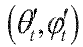


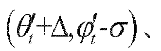


Area surrounded by those four points

where, ϑ(Δ,σ) is function of Δ, σ, when Δ and σ are constant, ϑ(Δ,σ) is also a constant as
- (3) In the space to be evaluated, the ratio of current processing unit


- (4) The quality Q of


- (5) The quality of the entire image is presented as

- The third embodiment of the patent relates to a digital image quality evaluation method. Several basic definitions need to be made. The observation space Wo to present observing digital images is a sphere. The representation space of digital images to be evaluated Wt is equi rectangular projection (ERP) format. The representation space of reference digital images Wrep is ERP format. The objective quality of digital images in the space to be evaluated is calculated as follows:
- (1) The space to be evaluated Wt and the reference space Wrep can be represented by affine transformation. To make sure that each pixel in the space to be evaluated Wt has corresponding pixel in the reference space Wrep , up-sampling and down-sampling can be operated if it is necessary, after which reference space Wrep is converted to new reference space


- (2) One pixel (θo ,ϕo ) in reference space Wrep is corresponding to


- (3) In the reference space, the ratio of current processing unit




- (4) The quality Q of


- (5) The quality of the entire image is presented as
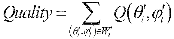
- The fourth embodiment of the patent relates to a digital image quality evaluation method. Several basic definitions need to be made. The observation space Wo to present observing digital images is a sphere. The representation space of digital images to be evaluated Wt is equi rectangular projection (ERP) format. The representation space of reference digital images Wrep is ERP format. The objective quality of digital images in the space to be evaluated is calculated as follows:
- (1) The space to be evaluated Wt and the reference space Wrep can be represented by affine transformation. To make sure that each pixel in the space to be evaluated Wt has corresponding pixel in the reference space Wrep, up-sampling and down-sampling can be operated if it is necessary, after which reference space Wrep is converted to new reference space


- (2) One pixel (θt ,ϕt ) in the space to be evaluated Wt is corresponding to







- (3) In the space to be evaluated, the ratio of current processing unit


- (4) The quality Q of
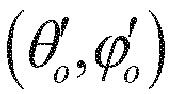


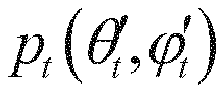


- (5) The quality of the entire image is presented as

- The fifth embodiment of the patent relates to a digital image quality evaluation method. Several basic definitions need to be made. The observation space Wo to present observing digital images is a sphere. The representation space of digital images to be evaluated Wt is equi rectangular projection (ERP) format. The representation space of reference digital images Wrep is ERP format. The objective quality of digital images in the space to be evaluated is calculated as follows:
- (1) The space to be evaluated Wt and the reference space Wrep can be represented by affine transformation. To make sure that each pixel in the space to be evaluated Wt has corresponding pixel in the reference space Wrep , up-sampling and down-sampling can be operated if it is necessary, after which reference space Wrep is converted to new reference space


- (2) One pixel (θo ,ϕo ) in reference space Wrep is corresponding to


In the reference space, the ratio of current processing unit


- (3) The quality Q of


- (4) The quality of the entire image is presented as

- The sixth embodiment of the patent relates to a digital image quality evaluation method. Several basic definitions need to be made. The observation space Wo to present observing digital images is a sphere. The representation space of digital images to be evaluated Wt is equi rectangular projection (ERP) format. The representation space of reference digital images Wrep is ERP format. The objective quality of digital images in the space to be evaluated is calculated as follows:
- (1) The space to be evaluated Wt and the reference space Wrep can be represented by affine transformation. To make sure that each pixel in the space to be evaluated Wt has corresponding pixel in the reference space Wrep, up-sampling and down-sampling can be operated if it is necessary, after which reference space Wrep is converted to new reference space


- (2) One pixel (θo ,ϕo ) in reference space Wrep is corresponding to



In the reference space, the ratio of current processing unit


- (3) The quality Q of

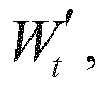





- (4) The quality of the entire image is presented as

- The seventh embodiment of the patent relates to a digital image quality evaluation method. Several basic definitions need to be made. The observation space Wo to present observing digital images is a sphere. The representation space of digital images to be evaluated Wt is equi rectangular projection (ERP) format. The representation space of reference digital images Wrep is ERP format. The objective quality of digital images in the space to be evaluated is calculated as follows:
- (1) The space to be evaluated Wt and the reference space Wrep can be represented by affine transformation. To make sure that each pixel in the space to be evaluated Wt has corresponding pixel in the reference space Wrep , up-sampling and down-sampling can be operated if it is necessary, after which reference space Wrep is converted to new reference space


- (2) One pixel (θo ,ϕo ) in reference space Wrep is corresponding to


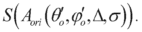
In the reference space, the ratio of current processing unit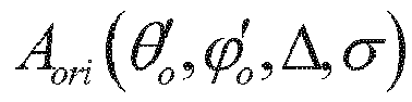



- (3) The quality Q of


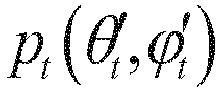


- (4) The quality of the entire image is presented as

- The eighth embodiment of the patent relates to a digital image quality evaluation method. Several basic definitions need to be made. The observation space Wo to present observing digital images is a sphere. The representation space of digital images to be evaluated Wt is equi rectangular projection (ERP) format. The representation space of reference digital images Wrep is ERP format. The objective quality of digital images in the space to be evaluated is calculated as follows:
- (1) The space to be evaluated Wt and the reference space Wrep can be represented by affine transformation. To make sure that each pixel in the space to be evaluated Wt has corresponding pixel in the reference space Wrep , up-sampling and down-sampling can be operated if it is necessary, after which reference space Wrep is converted to new reference space


- (2) One pixel (θo ,ϕo ) in reference space Wrep is corresponding to


In the reference space, the ratio of current processing unit


- (3) The quality Q of


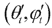
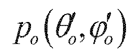

- (4) The quality of the entire image is presented as

- The ninth embodiment of the patent relates to a digital image quality evaluation method. Several basic definitions need to be made. The observation space Wo to present observing digital images is a sphere. The representation space of digital images to be evaluated Wt is equi rectangular projection (ERP) format. The representation space of reference digital images Wrep is ERP format. The objective quality of digital images in the space to be evaluated is calculated as follows:
- (1) The space to be evaluated Wt and the reference space Wrep can be represented by affine transformation. To make sure that each pixel in the space to be evaluated Wt has corresponding pixel in the reference space Wrep , up-sampling and down-sampling can be operated if it is necessary, after which reference space Wrep is converted to new reference space


- (2) One pixel (θt ,ϕt ) in the space to be evaluated Wt is corresponding to



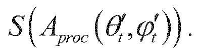
- (3) In the space to be evaluated, the ratio of current processing unit


- (4) The quality Q of


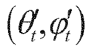


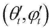


- (5) The quality of the entire image is presented as

- The tenth embodiment of the patent relates to a digital image quality evaluation method. Several basic definitions need to be made. The observation space Wo to present observing digital images is a sphere. The representation space of digital images to be evaluated Wt is equi rectangular projection (ERP) format. The representation space of reference digital images Wrep is ERP format. The objective quality of digital images in the space to be evaluated is calculated as follows:
- (1) The space to be evaluated Wt and the reference space Wrep can be represented by affine transformation. To make sure that each pixel in the space to be evaluated Wt has corresponding pixel in the reference space Wrep, up-sampling and down-sampling can be operated if it is necessary, after which reference space Wrep is converted to new reference space


- (2) One pixel (θt ,ϕt ) in the space to be evaluated Wt is corresponding to


- (3) In the space to be evaluated, the ratio of current processing unit


- (4) The quality Q of



- (5) The quality of the entire image is presented as

- The eleventh embodiment of the patent relates to a digital image quality evaluation method. Several basic definitions need to be made. The observation space Wo to present observing digital images is a sphere. The representation space of digital images to be evaluated Wt is equi rectangular projection (ERP) format. The representation space of reference digital images Wrep is ERP format. The objective quality of digital images in the space to be evaluated is calculated as follows:
- (1) The space to be evaluated Wt and the reference space Wrep can be represented by affine transformation. To make sure that each pixel in the space to be evaluated Wt has corresponding pixel in the reference space Wrep , up-sampling and down-sampling can be operated if it is necessary, after which reference space Wrep is converted to new reference space


- (2) One pixel (θt ,ϕt ) in the space to be evaluated Wt is corresponding to


- (3) In the space to be evaluated, the ratio of current processing unit


- (4) The quality Q of


- (5) The quality of the entire image is presented as

- The twelfth embodiment of the patent relates to a digital image quality evaluation method. Several basic definitions need to be made. The observation space Wo to present observing digital images is a sphere. The representation space of digital images to be evaluated Wt is equi rectangular projection (ERP) format. The representation space of reference digital images Wrep is ERP format. The objective quality of digital images in the space to be evaluated is calculated as follows:
- (1) The space to be evaluated Wt and the reference space Wrep can be represented by affine transformation. To make sure that each pixel in the space to be evaluated Wt has corresponding pixel in the reference space Wrep, up-sampling and down-sampling can be operated if it is necessary, after which reference space Wrep is converted to new reference space


- (2) One pixel (θt ,ϕt ) in the space to be evaluated Wt is corresponding to

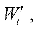


- (3) In the space to be evaluated, the ratio of current processing unit


- (4) The quality Q of


- (5) The quality of the entire image is presented as

- The thirteenth embodiment of the patent relates to a digital image quality evaluation method. Several basic definitions need to be made. The observation space Wo to present observing digital images is a sphere. The representation space of digital images to be evaluated Wt is cube map projection (CMP) format. The representation space of reference digital images Wrep is CMP format. The objective quality of digital images in the space to be evaluated is calculated as follows:
- (1) The space to be evaluated Wt and the reference space Wrep can be represented by affine transformation. To make sure that each pixel in the space to be evaluated Wt has corresponding pixel in the reference space Wrep , up-sampling and down-sampling can be operated if it is necessary, after which reference space Wrep is converted to new reference space


- (2) One pixel (xo ,yo ,zo ) in reference space Wrep is corresponding to




- (3) In the reference space, the ratio of current processing unit



- (4) The quality Q of





- (5) The quality of the entire image is presented as

- The fourteenth embodiment of the patent relates to a digital image quality evaluation method. Several basic definitions need to be made. The observation space Wo to present observing digital images is a sphere. The representation space of digital images to be evaluated Wt is cube map projection (CMP) format. The representation space of reference digital images Wrep is CMP format. The objective quality of digital images in the space to be evaluated is calculated as follows:
- (1) The space to be evaluated Wt and the reference space Wrep can be represented by affine transformation. To make sure that each pixel in the space to be evaluated Wt has corresponding pixel in the reference space Wrep, up-sampling and down-sampling can be operated if it is necessary, after which reference space Wrep is converted to new reference space


- (2) One pixel (xt ,yt ,zt ) in the space to be evaluated Wt is corresponding to


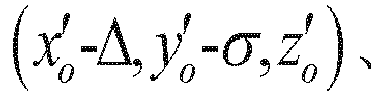


- (3) In the space to be evaluated, the ratio of current processing unit


- (4) The quality Q of


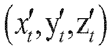


- (5) The quality of the entire image is presented as

- The fifteenth embodiment of the patent relates to a digital image quality evaluation method. Several basic definitions need to be made. The observation space Wo to present observing digital images is a sphere. The representation space of digital images to be evaluated Wt is cube map projection (CMP) format. The representation space of reference digital images Wrep is CMP format. The objective quality of digital images in the space to be evaluated is calculated as follows:
- (1) The space to be evaluated Wt and the reference space Wrep can be represented by affine transformation. To make sure that each pixel in the space to be evaluated Wt has corresponding pixel in the reference space Wrep , up-sampling and down-sampling can be operated if it is necessary, after which reference space Wrep is converted to new reference space


- (2) One pixel (xo,y o ,z o ) in reference space Wrep is corresponding to


- (3) In the reference space, the ratio of current processing unit


- (4) The quality Q of


- (5) The quality of the entire image is presented as

- The sixteenth embodiment of the patent relates to a digital image quality evaluation method. Several basic definitions need to be made. The observation space Wo to present observing digital images is a sphere. The representation space of digital images to be evaluated Wt is cube map projection (CMP) format. The representation space of reference digital images Wrep is CMP format. The objective quality of digital images in the space to be evaluated is calculated as follows:
- (1) The space to be evaluated Wt and the reference space Wrep can be represented by affine transformation. To make sure that each pixel in the space to be evaluated Wt has corresponding pixel in the reference space Wrep , up-sampling and down-sampling can be operated if it is necessary, after which reference space Wrep is converted to new reference space


- (2) One pixel (xt ,y t ,z t ) in the space to be evaluated Wt is corresponding to


- (3) In the space to be evaluated, the ratio of current processing unit


- (4) The quality Q of

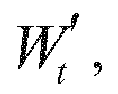
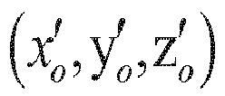


- (5) The quality of the entire image is presented as

- The seventeenth embodiment of the patent relates to a digital image quality evaluation method. Several basic definitions need to be made. The observation space Wo to present observing digital images is a sphere. The representation space of digital images to be evaluated Wt is cube map projection (CMP) format. The representation space of reference digital images Wrep is CMP format. The objective quality of digital images in the space to be evaluated is calculated as follows:
- (1) The space to be evaluated Wt and the reference space Wrep can be represented by affine transformation. To make sure that each pixel in the space to be evaluated Wt has corresponding pixel in the reference space Wrep , up-sampling and down-sampling can be operated if it is necessary, after which reference space Wrep is converted to new reference space


- (2) One pixel (xo ,y o ,z o ) in reference space Wrep is corresponding to


- (3) In the reference space, the ratio of current processing unit


- (4) The quality Q of


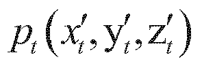


- (5) The quality of the entire image is presented as

- The eighteenth embodiment of the patent relates to a digital image quality evaluation method. Several basic definitions need to be made. The observation space Wo to present observing digital images is a sphere. The representation space of digital images to be evaluated Wt is cube map projection (CMP) format. The representation space of reference digital images Wrep is CMP format. The objective quality of digital images in the space to be evaluated is calculated as follows:
- (1) The space to be evaluated Wt and the reference space Wrep can be represented by affine transformation. To make sure that each pixel in the space to be evaluated Wt has corresponding pixel in the reference space Wrep, up-sampling and down-sampling can be operated if it is necessary, after which reference space Wrep is converted to new reference space


- (2) One pixel (xo,y o ,z o ) in reference space Wrep is corresponding to


- (3) In the reference space, the ratio of current processing unit


- (4) The quality Q of


- (5) The quality of the entire image is presented as

- The nineteenth embodiment of the patent relates to a digital image quality evaluation method. Several basic definitions need to be made. The observation space Wo to present observing digital images is a sphere. The representation space of digital images to be evaluated Wt is cube map projection (CMP) format. The representation space of reference digital images Wrep is CMP format. The objective quality of digital images in the space to be evaluated is calculated as follows:
- (1) The space to be evaluated Wt and the reference space Wrep can be represented by affine transformation. To make sure that each pixel in the space to be evaluated Wt has corresponding pixel in the reference space Wrep, up-sampling and down-sampling can be operated if it is necessary, after which reference space Wrep is converted to new reference space


- (2) One pixel (xo,y o ,z o ) in reference space Wrep is corresponding to



- (3) In the reference space, the ratio of current processing unit


- (4) The quality Q of

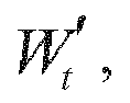
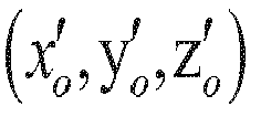




- (5) The quality of the entire image is presented as

- The twentieth embodiment of the patent relates to a digital image quality evaluation method. Several basic definitions need to be made. The observation space Wo to present observing digital images is a sphere. The representation space of digital images to be evaluated Wt is cube map projection (CMP) format. The representation space of reference digital images Wrep is CMP format. The objective quality of digital images in the space to be evaluated is calculated as follows:
- (1) The space to be evaluated Wt and the reference space Wrep can be represented by affine transformation. To make sure that each pixel in the space to be evaluated Wt has corresponding pixel in the reference space Wrep, up-sampling and down-sampling can be operated if it is necessary, after which reference space Wrep is converted to new reference space


- (2) One pixel (xo,y o ,z o ) in reference space Wrep is corresponding to


- (3) In the reference space, the ratio of current processing unit


- (4) The quality Q of


- (5) The quality of the entire image is presented as

- The twenty-first embodiment of the patent relates to a digital image quality evaluation method. Several basic definitions need to be made. The observation space Wo to present observing digital images is a sphere. The representation space of digital images to be evaluated Wt is cube map projection (CMP) format. The representation space of reference digital images Wrep is CMP format. The objective quality of digital images in the space to be evaluated is calculated as follows:
- (1) The space to be evaluated Wt and the reference space Wrep can be represented by affine transformation. To make sure that each pixel in the space to be evaluated Wt has corresponding pixel in the reference space Wrep, up-sampling and down-sampling can be operated if it is necessary, after which reference space Wrep is converted to new reference space


- (2) One pixel (xt ,y t ,z t ) in the space to be evaluated Wt is corresponding to


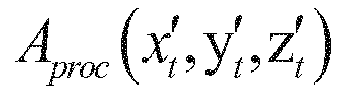

- (3) In the space to be evaluated, the ratio of current processing unit


- (4) The quality Q of


- (5) The quality of the entire image is presented as

- The twenty-second embodiment of the patent relates to a digital image quality evaluation method. Several basic definitions need to be made. The observation space Wo to present observing digital images is a sphere. The representation space of digital images to be evaluated Wt is cube map projection (CMP) format. The representation space of reference digital images Wrep is CMP format. The objective quality of digital images in the space to be evaluated is calculated as follows:
- (1) The space to be evaluated Wt and the reference space Wrep can be represented by affine transformation. To make sure that each pixel in the space to be evaluated Wt has corresponding pixel in the reference space Wrep, up-sampling and down-sampling can be operated if it is necessary, after which reference space Wrep is converted to new reference space


- (2) One pixel (x t ,y t ,z t ) in the space to be evaluated Wt is corresponding to


- (3) In the space to be evaluated, the ratio of current processing unit


- (4) The quality Q of


- (5) The quality of the entire image is presented as

- The twenty-third embodiment of the patent relates to a digital image quality evaluation method. Several basic definitions need to be made. The observation space Wo to present observing digital images is a sphere. The representation space of digital images to be evaluated Wt is cube map projection (CMP) format. The representation space of reference digital images Wrep is CMP format. The objective quality of digital images in the space to be evaluated is calculated as follows:
- (1) The space to be evaluated Wt and the reference space Wrep can be represented by affine transformation. To make sure that each pixel in the space to be evaluated Wt has corresponding pixel in the reference space Wrep, up-sampling and down-sampling can be operated if it is necessary, after which reference space Wrep is converted to new reference space


- (2) One pixel (x t ,y t ,z t ) in the space to be evaluated Wt is corresponding to


- (3) In the space to be evaluated, the ratio of current processing unit


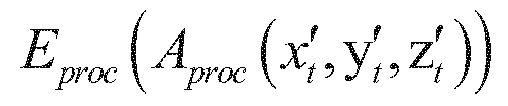
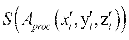
- (4) The quality Q of


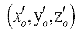


- (5) The quality of the entire image is presented as

- The twenty-fourth embodiment of the patent relates to a digital image quality evaluation method. Several basic definitions need to be made. The observation space Wo to present observing digital images is a sphere. The representation space of digital images to be evaluated Wt is cube map projection (CMP) format. The representation space of reference digital images Wrep is CMP format. The objective quality of digital images in the space to be evaluated is calculated as follows:
- (1) The space to be evaluated Wt and the reference space Wrep can be represented by affine transformation. To make sure that each pixel in the space to be evaluated Wt has corresponding pixel in the reference space Wrep, up-sampling and down-sampling can be operated if it is necessary, after which reference space Wrep is converted to new reference space


- (2) One pixel (xt ,y t ,z t ) in the space to be evaluated Wt is corresponding to


- (3) In the space to be evaluated, the ratio of current processing unit
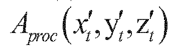


- (4) The quality Q of





- (5) The quality of the entire image is presented as

- The twenty-fifth embodiment of the patent relates to a digital image quality evaluation method. Several basic definitions need to be made. The observation space of digital images is Wo . The representation space of digital images is Wrep and the representation space of reference digital images is Wrep . The combination of Wt ,Wo and Wrep can be (ERP, sphere, ERP), (CMP, sphere, ERP), (ERP, sphere, CMP), (CMP, sphere, CMP), (rectangular pyramid, sphere, ERP), (ERP, sphere, rectangular pyramid), (rectangular pyramid, sphere, rectangular pyramid), (N-face format, sphere, M-face format), (ERP, sphere, M-face format) and (M-face format, sphere, ERP). But combinations are not limited to the above examples. The objective quality of digital images in the space to be evaluated is calculated as follows:
- (1) The space to be evaluated Wt and the reference space Wrep can be represented by affine transformation. To make sure that each pixel in the space to be evaluated Wt has corresponding pixel in the reference space Wrep, up-sampling and down-sampling can be operated if it is necessary, after which reference space Wrep is converted to new reference space


- (2) One pixel xo in reference space Wrep is corresponding to


- (3) In the reference space, the ratio of current processing unit


- (4) The quality Q of


- (5) The quality of the entire image is presented as

- The twenty-sixth embodiment of the patent relates to a digital image quality evaluation method. Several basic definitions need to be made. The observation space of digital images is Wo . The representation space of digital images is Wrep and the representation space of reference digital images is Wrep . The combination of Wt ,Wo and Wrep can be (ERP, sphere, ERP), (CMP, sphere, ERP), (ERP, sphere, CMP), (CMP, sphere, CMP), (rectangular pyramid, sphere, ERP), (ERP, sphere, rectangular pyramid), (rectangular pyramid, sphere, rectangular pyramid), (N-face format, sphere, M-face format), (ERP, sphere, M-face format) and (M-face format, sphere, ERP). But combinations are not limited to the above examples. The objective quality of digital images in the space to be evaluated is calculated as follows:
- (1) The space to be evaluated Wt and the reference space Wrep can be represented by affine transformation. To make sure that each pixel in the space to be evaluated Wt has corresponding pixel in the reference space Wrep , up-sampling and down-sampling can be operated if it is necessary, after which reference space Wrep is converted to new reference space


- (2) One pixel xo in reference space Wrep is corresponding to


- (3) In the reference space, the ratio of current processing unit


- (4) The quality Q of


- (5) The quality of the entire image is presented as
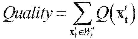
- The twenty-seventh embodiment of the patent relates to a digital image quality evaluation method. Several basic definitions need to be made. The observation space of digital images is Wo . The representation space of digital images is Wrep and the representation space of reference digital images is Wrep . The combination of Wt ,Wo and Wrep can be (ERP, sphere, ERP), (CMP, sphere, ERP), (ERP, sphere, CMP), (CMP, sphere, CMP), (rectangular pyramid, sphere, ERP), (ERP, sphere, rectangular pyramid), (rectangular pyramid, sphere, rectangular pyramid), (N-face format, sphere, M-face format), (ERP, sphere, M-face format) and (M-face format, sphere, ERP). But combinations are not limited to the above examples. The objective quality of digital images in the space to be evaluated is calculated as follows:
- (1) The space to be evaluated Wt and the reference space Wrep can be represented by affine transformation. To make sure that each pixel in the space to be evaluated Wt has corresponding pixel in the reference space Wrep , up-sampling and down-sampling can be operated if it is necessary, after which reference space Wrep is converted to new reference space


- (2) One pixel xo in reference space Wrep is corresponding to

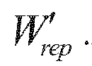


- (3) In the reference space, the ratio of current processing unit

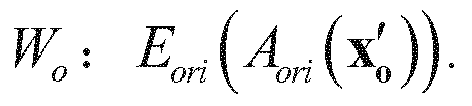


- (4) The quality Q of







- (5) The quality of the entire image is presented as

- The twenty-eighth embodiment of the patent relates to a digital image quality evaluation method. Several basic definitions need to be made. The observation space of digital images is Wo . The representation space of digital images is Wt and the representation space of reference digital images is Wrep . The combination of Wt ,Wo and Wrep can be (ERP, sphere, ERP), (CMP, sphere, ERP), (ERP, sphere, CMP), (CMP, sphere, CMP), (rectangular pyramid, sphere, ERP), (ERP, sphere, rectangular pyramid), (rectangular pyramid, sphere, rectangular pyramid), (N-face format, sphere, M-face format), (ERP, sphere, M-face format) and (M-face format, sphere, ERP). But combinations are not limited to the above examples. The objective quality of digital images in the space to be evaluated is calculated as follows:
- (1) The space to be evaluated Wt and the reference space Wrep can be represented by affine transformation. To make sure that each pixel in the space to be evaluated Wt has corresponding pixel in the reference space Wrep , up-sampling and down-sampling can be operated if it is necessary, after which reference space Wrep is converted to new reference space


- (2) One pixel xo in reference space Wrep is corresponding to


- (3) In the reference space, the ratio of current processing unit
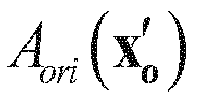


- (4) The quality Q of


- (5) The quality of the entire image is presented as

- The twenty-ninth embodiment of the patent relates to a digital image quality evaluation method. Several basic definitions need to be made. The observation space of digital images is Wo . The representation space of digital images is Wt and the representation space of reference digital images is Wrep . The combination of Wt ,Wo and Wrep can be (ERP, sphere, ERP), (CMP, sphere, ERP), (ERP, sphere, CMP), (CMP, sphere, CMP), (rectangular pyramid, sphere, ERP), (ERP, sphere, rectangular pyramid), (rectangular pyramid, sphere, rectangular pyramid), (N-face format, sphere, M-face format), (ERP, sphere, M-face format) and (M-face format, sphere, ERP). But combinations are not limited to the above examples. The objective quality of digital images in the space to be evaluated is calculated as follows:
- (1) The space to be evaluated Wt and the reference space Wrep can be represented by affine transformation. To make sure that each pixel in the space to be evaluated Wt has corresponding pixel in the reference space Wrep , up-sampling and down-sampling can be operated if it is necessary, after which reference space Wo is converted to new reference space


- (2) One pixel xo in reference space Wrep is corresponding to


- (3) In the reference space, the ratio of current processing unit
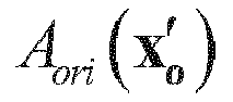


- (4) The quality Q of

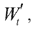


- (5) The quality of the entire image is presented as

- The thirtieth embodiment of the patent relates to a digital image quality evaluation method. Several basic definitions need to be made. The observation space of digital images is Wo . The representation space of digital images is Wt and the representation space of reference digital images is Wrep . The combination of Wt ,Wo and Wrep can be (ERP, sphere, ERP), (CMP, sphere, ERP), (ERP, sphere, CMP), (CMP, sphere, CMP), (rectangular pyramid, sphere, ERP), (ERP, sphere, rectangular pyramid), (rectangular pyramid, sphere, rectangular pyramid), (N-face format, sphere, M-face format), (ERP, sphere, M-face format) and (M-face format, sphere, ERP). But combinations are not limited to the above examples. The objective quality of digital images in the space to be evaluated is calculated as follows:
- (1) The space to be evaluated Wt and the reference space Wrep can be represented by affine transformation. To make sure that each pixel in the space to be evaluated Wt has corresponding pixel in the reference space Wrep, up-sampling and down-sampling can be operated if it is necessary, after which reference space Wrep is converted to new reference space


- (2) One pixel xo in reference space Wrep is corresponding to


- (3) In the reference space, the ratio of current processing unit


- (4) The quality Q of


- (5) The quality of the entire image is presented as

- The thirty-first embodiment of the patent relates to a digital image quality evaluation method. Several basic definitions need to be made. The observation space of digital images is Wo. The representation space of digital images is Wt and the representation space of reference digital images is Wrep .The combination of Wt ,Wo and Wrep can be (ERP, sphere, ERP), (CMP, sphere, ERP), (ERP, sphere, CMP), (CMP, sphere, CMP), (rectangular pyramid, sphere, ERP), (ERP, sphere, rectangular pyramid), (rectangular pyramid, sphere, rectangular pyramid), (N-face format, sphere, M-face format), (ERP, sphere, M-face format) and (M-face format, sphere, ERP). But combinations are not limited to the above examples. The objective quality of digital images in the space to be evaluated is calculated as follows:
- (1) The space to be evaluated Wt and the reference space Wrep can be represented by affine transformation. To make sure that each pixel in the space to be evaluated Wt has corresponding pixel in the reference space Wrep, up-sampling and down-sampling can be operated if it is necessary, after which reference space Wrep is converted to new reference space


- (2) One pixel xt in the space to be evaluated Wt is corresponding to


- (3) In the space to be evaluated, the ratio of area of


- (4) The quality Q of


- (5) The quality of the entire image is presented as

- The thirty-second embodiment of the patent relates to a digital image quality evaluation method. Several basic definitions need to be made. The observation space of digital images is Wo. The representation space of digital images is Wt and the representation space of reference digital images is Wrep . The combination of Wt,Wo and Wrep can be (ERP, sphere, ERP), (CMP, sphere, ERP), (ERP, sphere, CMP), (CMP, sphere, CMP), (rectangular pyramid, sphere, ERP), (ERP, sphere, rectangular pyramid), (rectangular pyramid, sphere, rectangular pyramid), (N-face format, sphere, M-face format), (ERP, sphere, M-face format) and (M-face format, sphere, ERP). But combinations are not limited to the above examples. The objective quality of digital images in the space to be evaluated is calculated as follows:
- (1) The space to be evaluated Wt and the reference space Wrep can be represented by affine transformation. To make sure that each pixel in the space to be evaluated Wt has corresponding pixel in the reference space Wrep, up-sampling and down-sampling can be operated if it is necessary, after which reference space Wrep is converted to new reference space


- (2) One pixel X t in the space to be evaluated Wt is corresponding to


- (3) In the space to be evaluated, the ratio of area of


- (4) The quality Q of


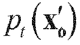

- (5) The quality of the entire image is presented as

- The thirty-third embodiment of the patent relates to a digital image quality evaluation method. Several basic definitions need to be made. The observation space of digital images is Wo . The representation space of digital images is Wt and the representation space of reference digital images is Wrep . The combination of Wt,Wo and Wrep can be (ERP, sphere, ERP), (CMP, sphere, ERP), (ERP, sphere, CMP), (CMP, sphere, CMP), (rectangular pyramid, sphere, ERP), (ERP, sphere, rectangular pyramid), (rectangular pyramid, sphere, rectangular pyramid), (N-face format, sphere, M-face format), (ERP, sphere, M-face format) and (M-face format, sphere, ERP). But combinations are not limited to the above examples. The objective quality of digital images in the space to be evaluated is calculated as follows:
- (1) The space to be evaluated Wt and the reference space Wrep can be represented by affine transformation. To make sure that each pixel in the space to be evaluated Wt has corresponding pixel in the reference space Wrep , up-sampling and down-sampling can be operated if it is necessary, after which reference space Wrep is converted to new reference space


- (2) One pixel X t in the space to be evaluated Wt is corresponding to


- (3) In the space to be evaluated, the ratio of area of


- (4) The quality Q of


- (5) The quality of the entire image is presented as

- The thirty-fourth embodiment of the patent relates to a digital image quality evaluation method. Several basic definitions need to be made. The observation space of digital images is Wo . The representation space of digital images is Wt and the representation space of reference digital images is Wrep .The combination of Wt,Wo and Wrep can be (ERP, sphere, ERP), (CMP, sphere, ERP), (ERP, sphere, CMP), (CMP, sphere, CMP), (rectangular pyramid, sphere, ERP), (ERP, sphere, rectangular pyramid), (rectangular pyramid, sphere, rectangular pyramid), (N-face format, sphere, M-face format), (ERP, sphere, M-face format) and (M-face format, sphere, ERP). But combinations are not limited to the above examples. The objective quality of digital images in the space to be evaluated is calculated as follows:
- (1) The space to be evaluated Wt and the reference space Wrep can be represented by affine transformation. To make sure that each pixel in the space to be evaluated Wt has corresponding pixel in the reference space Wrep, up-sampling and down-sampling can be operated if it is necessary, after which reference space Wrep is converted to new reference space


- (2) One pixel X t in the space to be evaluated Wt is corresponding to

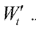


- (3) In the space to be evaluated, the ratio of area of


- (4) The quality Q of


- (5) The quality of the entire image is presented as

- The thirty-fifth embodiment of the patent relates to a digital image quality evaluation method. Several basic definitions need to be made. The observation space of digital images is Wo . The representation space of digital images is Wt and the representation space of reference digital images is Wrep .The combination of Wt,Wo and Wrep can be (ERP, sphere, ERP), (CMP, sphere, ERP), (ERP, sphere, CMP), (CMP, sphere, CMP), (rectangular pyramid, sphere, ERP), (ERP, sphere, rectangular pyramid), (rectangular pyramid, sphere, rectangular pyramid), (N-face format, sphere, M-face format), (ERP, sphere, M-face format) and (M-face format, sphere, ERP). But combinations are not limited to the above examples. The objective quality of digital images in the space to be evaluated is calculated as follows:
- (1) The space to be evaluated Wt and the reference space Wrep can be represented by affine transformation. To make sure that each pixel in the space to be evaluated Wt has corresponding pixel in the reference space Wrep, up-sampling and down-sampling can be operated if it is necessary, after which reference space Wrep is converted to new reference space


- (2) One pixel X t in the space to be evaluated Wt is corresponding to


- (3) In the space to be evaluated, the ratio of area of


- (4) The quality Q of


- (5) The quality of the entire image is presented as

- The thirty-sixth embodiment of the patent relates to a digital image quality evaluation method. Several basic definitions need to be made. The observation space of digital images is Wo . The representation space of digital images is Wt and the representation space of reference digital images is Wrep . The combination of Wt,Wo and Wrep can be (ERP, sphere, ERP), (CMP, sphere, ERP), (ERP, sphere, CMP), (CMP, sphere, CMP), (rectangular pyramid, sphere, ERP), (ERP, sphere, rectangular pyramid), (rectangular pyramid, sphere, rectangular pyramid), (N-face format, sphere, M-face format), (ERP, sphere, M-face format) and (M-face format, sphere, ERP). But combinations are not limited to the above examples. The objective quality of digital images in the space to be evaluated is calculated as follows:
- (1) The space to be evaluated Wt and the reference space Wrep can be represented by affine transformation. To make sure that each pixel in the space to be evaluated Wt has corresponding pixel in the reference space Wrep, up-sampling and down-sampling can be operated if it is necessary, after which reference space Wrep is converted to new reference space


- (2) One pixel X t in the space to be evaluated Wt is corresponding to


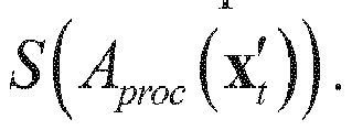
- (3) In the space to be evaluated, the ratio of area of

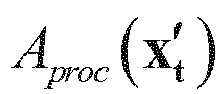


- (4) The quality Q of


- (5) The quality of the entire image is presented as

- The thirty-seventh embodiment of the patent relates to a digital image quality evaluation apparatus. Several basic definitions need to be made. The observation space of digital images is Wo . The representation space of digital images is Wt and the representation space of reference digital images is Wrep. The combination of Wt,Wo and Wrep can be (ERP, sphere, ERP), (CMP, sphere, ERP), (ERP, sphere, CMP), (CMP, sphere, CMP), (rectangular pyramid, sphere, ERP), (ERP, sphere, rectangular pyramid), (rectangular pyramid, sphere, rectangular pyramid), (N-face format, sphere, M-face format), (ERP, sphere, M-face format) and (M-face format, sphere, ERP). But combinations are not limited to the above examples. The objective quality module of digital images in the space to be evaluated is described as follows:
- (1) Distortion generation module, convert current processing unit Aproc in the space to be evaluated Wt to the new space to be evaluated


- (2) Weighted distortion processing module, map the current processing unit Aproc in the space to be evaluated Wt to the observation space, the ratio of area S(Aproc ) in current processing unit Aproc of space to be evaluated to observation space Wo can be presented as Eproc (Aproc ), and Eproc (Aproc ) is relate to the location of S(Aproc ) in the observation space Wo , which is not a constant;
- (3) The region surrounded by three nearest processing units of current processing unit is marked as Bproc. Mapping this region into observation space, the area is S(Bproc ). And the ratio of this mapping area on whole sphere is Eproc (Aproc )= S(Bproc )/whole area on observation space. The distortion value is multiplied by this ratio Eproc (Aproc ).
- (4) Quality evaluation module, using the processed distortion


- The thirty-eighth embodiment of the patent relates to a digital image quality evaluation apparatus. Several basic definitions need to be made. The observation space of digital images is Wo . The representation space of digital images is Wt and the representation space of reference digital images is Wrep .The combination of Wt,Wo and Wrep can be (ERP, sphere, ERP), (CMP, sphere, ERP), (ERP, sphere, CMP), (CMP, sphere, CMP), (rectangular pyramid, sphere, ERP), (ERP, sphere, rectangular pyramid), (rectangular pyramid, sphere, rectangular pyramid), (N-face format, sphere, M-face format), (ERP, sphere, M-face format) and (M-face format, sphere, ERP). But combinations are not limited to the above examples. The objective quality module of digital images in the space to be evaluated is described as follows:
- (1) Distortion generation module, convert current processing unit Aproc in the space to be evaluated Wt to the new space to be evaluated


- (2) Weighted distortion processing module, map the current processing unit Aori in reference space Wrep to the observation space, the ratio of area S(Aori ) in current processing unit Aori of reference space to observation space Wo can be presented as Eori (Aori ), and Eori (Aori ) is relate to the location of S(Aori ) in the observation space Wo , which is not a constant;
- (3) The region surrounded by three nearest processing units of current processing unit is marked as Bori . Mapping this region into observation space, the area is S(Bori ). And the ratio of this mapping area on whole sphere is Eori (Aori )= S(Bori )/whole area on observation space. The distortion value is multiplied by this ratio Eori (Aori ).
- (4) Quality evaluation module, using the processed distortion


- The thirty-ninth embodiment of the patent relates to a digital image quality evaluation apparatus. Several basic definitions need to be made. The observation space of digital images is Wo . The representation space of digital images is Wt and the representation space of reference digital images is Wrep . The combination of Wt,Wo and Wrep can be (ERP, sphere, ERP), (CMP, sphere, ERP), (ERP, sphere, CMP), (CMP, sphere, CMP), (rectangular pyramid, sphere, ERP), (ERP, sphere, rectangular pyramid), (rectangular pyramid, sphere, rectangular pyramid), (N-face format, sphere, M-face format), (ERP, sphere, M-face format) and (M-face format, sphere, ERP). But combinations are not limited to the above examples. The objective quality module of digital images in the space to be evaluated is described as follows:
- (1) Distortion generation module, convert current processing unit Aproc in the space to be evaluated Wt to the new space to be evaluated


- (2) Weighted distortion processing module, map the current processing unit Aproc in the space to be evaluated Wt to the observation space, the ratio of area S(Aproc ) in current processing unit Aproc of space to be evaluated to observation space Wo can be presented as Eproc (Aproc ), and Eproc (Aproc ) is relate to the location of S(Aproc ) in the observation space Wo , which is not a constant;
- (3) The region surrounded by four nearest processing units of current processing unit is marked as Bproc. Mapping this region into observation space, the area is S(Bproc ). And the ratio of this mapping area on whole sphere is Eproc (Aproc )= S(Bproc )/whole area on observation space. The distortion value is multiplied by this ratio Eproc (Aproc ).
- (4) Quality evaluation module, using the processed distortion


- The fortieth embodiment of the patent relates to a digital image quality evaluation apparatus. Several basic definitions need to be made. The observation space of digital images is Wo . The representation space of digital images is Wt and the representation space of reference digital images is Wrep .The combination of Wt, Wo and Wrep can be (ERP, sphere, ERP), (CMP, sphere, ERP), (ERP, sphere, CMP), (CMP, sphere, CMP), (rectangular pyramid, sphere, ERP), (ERP, sphere, rectangular pyramid), (rectangular pyramid, sphere, rectangular pyramid), (N-face format, sphere, M-face format), (ERP, sphere, M-face format) and (M-face format, sphere, ERP). But combinations are not limited to the above examples. The objective quality module of digital images in the space to be evaluated is described as follows:
- (1) Distortion generation module, convert current processing unit Aproc in the space to be evaluated Wt to the new space to be evaluated



- (2) Weighted distortion processing module, map the current processing unit Aori in reference space Wrep to the observation space, the ratio of area S(Aori ) in current processing unit Aori of reference space to observation space Wo can be presented as Eori (Aori ), and Eori (Aori ) is relate to the location of S(Aori ) in the observation space Wo , which is not a constant;
- (3) The region surrounded by four nearest processing units of current processing unit is marked as Bori. Mapping this region into observation space, the area is S(Bori ). And the ratio of this mapping area on whole sphere is Eori (Aori ) = S(Bori )/whole area on observation space. The distortion value is multiplied by this ratio Eori (Aori ).
- (4) Quality evaluation module, using the processed distortion


- The forty-first embodiment of the patent relates to a digital image quality evaluation apparatus. Several basic definitions need to be made. The observation space of digital images is Wo . The representation space of digital images is Wt and the representation space of reference digital images is Wrep. The combination of Wt,Wo and Wrep can be (ERP, sphere, ERP), (CMP, sphere, ERP), (ERP, sphere, CMP), (CMP, sphere, CMP), (rectangular pyramid, sphere, ERP), (ERP, sphere, rectangular pyramid), (rectangular pyramid, sphere, rectangular pyramid), (N-face format, sphere, M-face format), (ERP, sphere, M-face format) and (M-face format, sphere, ERP). But combinations are not limited to the above examples. The objective quality module of digital images in the space to be evaluated is described as follows:
- (1) Distortion generation module, convert current processing unit Aproc in the space to be evaluated Wt to the new space to be evaluated


- (2) Weighted distortion processing module, map the current processing unit Aproc in the space to be evaluated Wt to the observation space, the ratio of area S(Aproc ) in current processing unit Aproc of space to be evaluated to observation space Wo can be presented as Eproc (Aproc ), and Eproc (Aproc ) is relate to the location of S(Aproc ) in the observation space Wo , which is not a constant;
- (3) The region surrounded by three nearest processing units and the center point of current processing unit is marked as Bproc. Mapping this region into observation space, the area is S(Bproc ). And the ratio of this mapping area on whole sphere is Eproc (Aproc ) = S(Bproc )/whole area on observation space. The distortion value is multiplied by this ratio Eproc (Aproc ) .
- (4) Quality evaluation module, using the processed distortion


- The forty-second embodiment of the patent relates to a digital image quality evaluation apparatus. Several basic definitions need to be made. The observation space of digital images is Wo . The representation space of digital images is Wt and the representation space of reference digital images is Wrep. The combination of Wt,Wo and Wrep can be (ERP, sphere, ERP), (CMP, sphere, ERP), (ERP, sphere, CMP), (CMP, sphere, CMP), (rectangular pyramid, sphere, ERP), (ERP, sphere, rectangular pyramid), (rectangular pyramid, sphere, rectangular pyramid), (N-face format, sphere, M-face format), (ERP, sphere, M-face format) and (M-face format, sphere, ERP). But combinations are not limited to the above examples. The objective quality module of digital images in the space to be evaluated is described as follows:
- (1) Distortion generation module, convert current processing unit Aproc in the space to be evaluated Wt to the new space to be evaluated

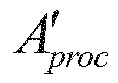

- (2) Weighted distortion processing module, map the current processing unit Aori in reference space Wrep to the observation space, the ratio of area S(Aori ) in current processing unit Aori of reference space to observation space Wo can be presented as Eori (Aori ), and Eori (Aori ) is relate to the location of S(Aori ) in the observation space Wo , which is not a constant;
- (3) The region surrounded by three nearest processing units and the center point of current processing unit is marked as Bori. Mapping this region into observation space, the area is S(Bori ). And the ratio of this mapping area on whole sphere is Eori (Aori ) = S(Bori )/whole area on observation space. The distortion value is multiplied by this ratio Eori (Aori ).
- (4) Quality evaluation module, using the processed distortion


- The forty-third embodiment of the patent relates to a digital image quality evaluation apparatus. Several basic definitions need to be made. The observation space of digital images is Wo . The representation space of digital images is Wt and the representation space of reference digital images is Wrep . The combination of Wt,Wo and Wrep can be (ERP, sphere, ERP), (CMP, sphere, ERP), (ERP, sphere, CMP), (CMP, sphere, CMP), (rectangular pyramid, sphere, ERP), (ERP, sphere, rectangular pyramid), (rectangular pyramid, sphere, rectangular pyramid), (N-face format, sphere, M-face format), (ERP, sphere, M-face format) and (M-face format, sphere, ERP). But combinations are not limited to the above examples. The objective quality module of digital images in the space to be evaluated is described as follows:
- (1) Distortion generation module, convert current processing unit Aproc in the space to be evaluated Wt to the new space to be evaluated


- (2) Weighted distortion processing module, map the current processing unit Aproc in the space to be evaluated Wt to the observation space, the ratio of area S(Aproc ) in current processing unit Aproc of space to be evaluated to observation space Wo can be presented as Eproc (Aproc ), and Eproc (Aproc ) is relate to the location of S(Aproc ) in the observation space Wo , which is not a constant;
- (3) The region surrounded by four nearest processing units and the center point of current processing unit is marked as Bproc. Mapping this region into observation space, the area is S(Bproc ). And the ratio of this mapping area on whole sphere is Eproc (Aproc ) = S(Bproc )/whole area on observation space. The distortion value is multiplied by this ratio Eproc (Aproc ) .
- (4) Quality evaluation module, using the processed distortion


- The forty-fourth embodiment of the patent relates to a digital image quality evaluation apparatus. Several basic definitions need to be made. The observation space of digital images is Wo . The representation space of digital images is Wt and the representation space of reference digital images is Wrep. The combination of Wt,Wo and Wrep can be (ERP, sphere, ERP), (CMP, sphere, ERP), (ERP, sphere, CMP), (CMP, sphere, CMP), (rectangular pyramid, sphere, ERP), (ERP, sphere, rectangular pyramid), (rectangular pyramid, sphere, rectangular pyramid), (N-face format, sphere, M-face format), (ERP, sphere, M-face format) and (M-face format, sphere, ERP). But combinations are not limited to the above examples. The objective quality module of digital images in the space to be evaluated is described as follows:
- (1) Distortion generation module, convert current processing unit Aproc in the space to be evaluated Wt to the new space to be evaluated


- (2) Weighted distortion processing module, map the current processing unit Aori in reference space Wrep to the observation space, the ratio of area S(Aori ) in current processing unit Aori of reference space to observation space Wo can be presented as Eori (Aori ), and Eori (Aori ) is relate to the location of S(Aori ) in the observation space Wo , which is not a constant;
- (3) The region surrounded by four nearest processing units and the center point of current processing unit is marked as Bori. Mapping this region into observation space, the area is S(Bori ). And the ratio of this mapping area on whole sphere is Eori (Aori ) = S(Bori )/whole area on observation space. The distortion value is multiplied by this ratio Eori (Aori ).
- (4) Quality evaluation module, using the processed distortion


- The forty-fifth embodiment of the patent relates to a digital image quality evaluation apparatus. Several basic definitions need to be made. The observation space of digital images is Wo . The representation space of digital images is Wt and the representation space of reference digital images is Wrep. The combination of Wt,Wo and Wrep can be (ERP, sphere, ERP), (CMP, sphere, ERP), (ERP, sphere, CMP), (CMP, sphere, CMP), (rectangular pyramid, sphere, ERP), (ERP, sphere, rectangular pyramid), (rectangular pyramid, sphere, rectangular pyramid), (N-face format, sphere, M-face format), (ERP, sphere, M-face format) and (M-face format, sphere, ERP). But combinations are not limited to the above examples. The objective quality module of digital images in the space to be evaluated is described as follows:
- (1) Distortion generation module, convert current processing unit Aproc in the space to be evaluated Wt to the new space to be evaluated


- (2) Weighted distortion processing module, map the current processing unit Aproc in the space to be evaluated Wt to the observation space, the ratio of area S(Aproc ) in current processing unit Aproc of space to be evaluated to observation space Wo can be presented as Eproc (Aproc ), and Eproc (Aproc ) is relate to the location of S(Aproc ) in the observation space Wo , which is not a constant;
- (3) The region within unit length of current processing unit is marked as Bproc. Mapping this region into observation space, the area is S(Bproc ). And the ratio of this mapping area on whole sphere is Eproc (Aproc ) = S(Bproc )/whole area on observation space. The distortion value is multiplied by this ratio Eproc (A proc ).
- (4) Quality evaluation module, using the processed distortion


- The forty-sixth embodiment of the patent relates to a digital image quality evaluation apparatus. Several basic definitions need to be made. The observation space of digital images is Wo . The representation space of digital images is Wt and the representation space of reference digital images is Wrep .The combination of Wt,Wo and Wrep can be (ERP, sphere, ERP), (CMP, sphere, ERP), (ERP, sphere, CMP), (CMP, sphere, CMP), (rectangular pyramid, sphere, ERP), (ERP, sphere, rectangular pyramid), (rectangular pyramid, sphere, rectangular pyramid), (N-face format, sphere, M-face format), (ERP, sphere, M-face format) and (M-face format, sphere, ERP). But combinations are not limited to the above examples. The objective quality module of digital images in the space to be evaluated is described as follows:
- (1) Distortion generation module, convert current processing unit Aproc in the space to be evaluated Wt to the new space to be evaluated


- (2) Weighted distortion processing module, map the current processing unit Aori in reference space Wrep to the observation space, the ratio of area S(Aori ) in current processing unit Aori of reference space to observation space Wo can be presented as Eori (Aori ), and Eori (Aori ) is relate to the location of S(Aori ) in the observation space Wo , which is not a constant;
- (3) The region within unit length of current processing unit is marked as Bori. Mapping this region into observation space, the area is S(Bori ). And the ratio of this mapping area on whole sphere is Eori (Aori ) = S(Bori )/whole area on observation space. The distortion value is multiplied by this ratio Eori (Aori ).
- (4) Quality evaluation module, using the processed distortion


- The forty-seventh embodiment of the patent relates to a digital image quality evaluation apparatus. Several basic definitions need to be made. The observation space of digital images is Wo . The representation space of digital images is Wt and the representation space of reference digital images is Wrep .The combination of Wt,Wo and Wrep can be (ERP, sphere, ERP), (CMP, sphere, ERP), (ERP, sphere, CMP), (CMP, sphere, CMP), (rectangular pyramid, sphere, ERP), (ERP, sphere, rectangular pyramid), (rectangular pyramid, sphere, rectangular pyramid), (N-face format, sphere, M-face format), (ERP, sphere, M-face format) and (M-face format, sphere, ERP). But combinations are not limited to the above examples. The objective quality module of digital images in the space to be evaluated is described as follows:
- (1) Distortion generation module, convert current processing unit Aproc in the space to be evaluated Wt to the new space to be evaluated


- (2) Weighted distortion processing module, map the current processing unit Aproc in the space to be evaluated Wt to the observation space, the ratio of area S (Aproc) in current processing unit Aproc of space to be evaluated to observation space Wo can be presented as Eproc (Aproc ), and Eproc (Aproc ) is relate to the location of S(Aproc ) in the observation space Wo , which is not a constant;
- (3) The region covered within unit length of current processing unit and center point of current processing unit is marked as Bproc . Mapping this region into observation space, the area is S(Bproc ). And the ratio of this mapping area on whole sphere is Eproc (Aproc ) = S(Bproc )/whole area on observation space. The distortion value is multiplied by this ratio Eproc (Aproc ).
- (4) Quality evaluation module, using the processed distortion


- The forty-eighth embodiment of the patent relates to a digital image quality evaluation apparatus. Several basic definitions need to be made. The observation space of digital images is Wo . The representation space of digital images is Wt and the representation space of reference digital images is Wrep. The combination of Wt,Wo and Wrep can be (ERP, sphere, ERP), (CMP, sphere, ERP), (ERP, sphere, CMP), (CMP, sphere, CMP), (rectangular pyramid, sphere, ERP), (ERP, sphere, rectangular pyramid), (rectangular pyramid, sphere, rectangular pyramid), (N-face format, sphere, M-face format), (ERP, sphere, M-face format) and (M-face format, sphere, ERP). But combinations are not limited to the above examples. The objective quality module of digital images in the space to be evaluated is described as follows:
- (1) Distortion generation module, convert current processing unit Aproc in the space to be evaluated Wt to the new space to be evaluated



- (2) Weighted distortion processing module, map the current processing unit Aori in reference space Wrep to the observation space, the ratio of area S(Aori ) in current processing unit Aori of reference space to observation space Wo can be presented as Eori (Aori ), and Eori (Aori ) is relate to the location of S(Aori ) in the observation space Wo , which is not a constant;
- (3) The region covered within unit length of current processing unit and center point of current processing unit is marked as Bori. Mapping this region into observation space, the area is S(Bori ). And the ratio of this mapping area on whole sphere is Eori (Aori ) = S(Bori )/whole area on observation space. The distortion value is multiplied by this ratio Eori (Aori ).
- (4) Quality evaluation module, using the processed distortion


- The forty-ninth embodiment of the patent relates to a digital image quality evaluation method. Several basic definitions need to be made. The observation space of digital images is Wo . The representation space of digital images is Wt and the representation space of reference digital images is Wrep . Wt and Wrep are the same, meaning that the images in reference space and the space to be evaluated share same format and resolution. For example, images in Wt and Wrep are both ERP or CMP. The observation space is difference from reference space or the space to be evaluated, e.g., sphere. The objective quality of digital images in the space to be evaluated is calculated as follows:
- (1) According to the mapping function between reference space or the space to be evaluated and observation space, the stretching ratio SR(x,y) of each position (x,y) in the space to be evaluated or reference space can be obtained. And the stretching ratio SR(x,y) is the ratio of mapping micro area δSrep of (x,y) in observation space to the micro area δS t/o of (x, y) in the space to be evaluated or reference space, i.e., δSrep /δS t/ o.
- (2) Determine the weight w(i,j) of each pixel in (i,j) in the space to be evaluated or reference space. The weight for quality evaluation is the stretching ratio SR(x,y) of each pixel. And the stretching ratio SR(x,y) of each pixel using the stretching ratio of center point in (x,y), which can be obtained according the mapping function between (i,j) and (x,y). It can be derived according to step 1. For example, the weights w(i,j) of ERP equal to

- (3) The objective quality of image with resolution of width * height is calculated as follows:

- The fiftieth embodiment of the patent relates to a digital image quality evaluation method. Several basic definitions need to be made. The observation space of digital images is Wo . The representation space of digital images is Wt and the representation space of reference digital images is Wrep . Wt and Wrep are the same, meaning that the images in reference space and the space to be evaluated share same format and resolution. For example, images in Wt and Wrep are both ERP or CMP. The observation space is difference from reference space or the space to be evaluated, e.g., sphere. The objective quality of digital images in the space to be evaluated is calculated as follows:
- (1) According to the mapping function between reference space or the space to be evaluated and observation space, the stretching ratio SR(x, y) of each position (x, y) in the space to be evaluated or reference space can be obtained. And the stretching ratio SR(x, y) is the ratio of mapping micro area δSrep of (x, y) in observation space to the micro area δS t/o of (x, y) in the space to be evaluated or reference space, i.e., δSrep / δS t/o .
- (2) Determine the weight w(i, j) of each pixel in (i, j) in the space to be evaluated or reference space. The weight for quality evaluation is the stretching ratio SR(x, y) of each pixel. And the stretching ratio SR(x, y) of each pixel using the average stretching ratio of pixel in (x, y), i.e. the region of (w, h): {(w,h)| i-0.5<=w<=i+0.5, j-0.5<=h<=j+0.5}. This can be obtained according the mapping function between (i, j) and (x, y). It can be derived according to step 1. For example, the weights w(i, j) of ERP equal to

- (3) The objective quality of image with resolution of width*height is calculated as follows:

- The fifty-first embodiment of the patent relates to a digital image quality evaluation method. Several basic definitions need to be made. The observation space of digital images is Wo . The representation space of digital images is Wt and the representation space of reference digital images is Wrep . Wt and Wrep are the same, meaning that the images in reference space and the space to be evaluated share same format and resolution. For example, images in Wt and Wrep are both ERP or CMP. The observation space is difference from reference space or the space to be evaluated, e.g., sphere. The objective quality of digital images in the space to be evaluated is calculated as follows:
- (1) According to the mapping function between reference space or the space to be evaluated and observation space, the stretching ratio SR(x, y) of each position (x, y) in the space to be evaluated or reference space can be obtained. And the stretching ratio SR(x, y) is the ratio of mapping micro area δSrep of (x, y) in observation space to the micro area δS t/o of (x, y) in the space to be evaluated or reference space, i.e., δSrep / δS t/ o.
- (2) Determine the weight w(i, j) of each pixel in (i, j) in the space to be evaluated or reference space. The weight for quality evaluation is the normalized stretching ratio SR(x, y) of each pixel so the sum of weights is 1. And the stretching ratio SR(x, y) of each pixel using the stretching ratio of center point in (x, y), which can be obtained according the mapping function between (i, j) and (x, y). It can be derived according to step 1.
- (3) The objective quality of image with resolution of width*height is calculated as follows:

- The fifty-second embodiment of the patent relates to a digital image quality evaluation method. Several basic definitions need to be made. The observation space of digital images is Wo . The representation space of digital images is Wt and the representation space of reference digital images is Wrep . Wt and Wrep are the same, meaning that the images in reference space and the space to be evaluated share same format and resolution. For example, images in Wt and Wrep are both ERP or CMP. The observation space is difference from reference space or the space to be evaluated, e.g., sphere. The objective quality of digital images in the space to be evaluated is calculated as follows:
- (1) According to the mapping function between reference space or the space to be evaluated and observation space, the stretching ratio SR(x, y) of each position (x, y) in the space to be evaluated or reference space can be obtained. And the stretching ratio SR(x, y) is the ratio of mapping micro area δSrep of (x, y) in observation space to the micro area δS t/o of (x, y) in the space to be evaluated or reference space, i.e., δSrep / δS t/ o.
- (2) Determine the weight w(i, j) of each pixel in (i, j) in the space to be evaluated or reference space. The weight for quality evaluation is the normalized stretching ratio SR(x, y) of each pixel so the sum of weights is 1. And the stretching ratio SR(x, y) of each pixel using the average stretching ratio of pixel in (x, y), i.e. the region of (w,h): {(w,h)|i-0.5<=w<=i+0.5, j-0.5<=h<=j+0.5}. This can be obtained according the mapping function between (i, j) and (x, y). It can be derived according to step 1.
- (3) The objective quality of image with resolution of width*height is calculated as follows:

- The fifty-third embodiment of the patent relates to a digital image quality evaluation apparatus. Several basic definitions need to be made. The observation space of digital images is Wo . The representation space of digital images is Wt and the representation space of reference digital images is Wrep. Wt and Wrep are the same, meaning that the images in reference space and the space to be evaluated share same format and resolution. For example, images in Wt and Wrep are both ERP or CMP. The observation space is difference from reference space or the space to be evaluated, e.g., sphere. The objective quality module of digital images in the space to be evaluated is described as follows:
- (1) The input of distortion generation module are images in the space to be evaluated and reference space, and output is distortion value. As the space to be evaluated and reference space are the same, the distortion can be directly obtained.
- (2) The input of weighted distortion processing module are image format and position, and the output is quality evaluation weights in different position. According to the mapping function between reference space or the space to be evaluated and observation space, the stretching ratio SR(x, y) of each position (x, y) in the space to be evaluated or reference space can be obtained. And the stretching ratio SR(x, y) is the ratio of mapping micro area δSrep of (x, y) in observation space to the micro area δS t/o of (x, y) in the space to be evaluated or reference space, i.e., δSrep / δS t/o .
- (3) Determine the weight w(i, j) of each pixel in (i, j) in the space to be evaluated or reference space. The weight for quality evaluation is the stretching ratio SR(x, y) of each pixel. And the stretching ratio SR(x, y) of each pixel using the stretching ratio of center point in (x, y), which can be obtained according the mapping function between (i, j) and (x, y). It can be derived according to step 1. For example, the weights w(i, j) of ERP equal to

- (4) The input of quality evaluation module are distortion values and weights. And output is the results of quality evaluation. The objective quality of image with resolution of width*height is calculated as follows:

- The fifty-fourth embodiment of the patent relates to a digital image quality evaluation apparatus. Several basic definitions need to be made. The observation space of digital images is Wo . The representation space of digital images is Wt and the representation space of reference digital images is Wrep. Wt and Wrep are the same, meaning that the images in reference space and the space to be evaluated share same format and resolution. For example, images in Wt and Wrep are both ERP or CMP. The observation space is difference from reference space or the space to be evaluated, e.g., sphere. The objective quality module of digital images in the space to be evaluated is described as follows:
- (1) The input of distortion generation module are images in the space to be evaluated and reference space, and output is distortion value. As the space to be evaluated and reference space are the same, the distortion can be directly obtained.
- (2) The input of weighted distortion processing module are image format and position, and the output is quality evaluation weights in different position. According to the mapping function between reference space or the space to be evaluated and observation space, the stretching ratio SR(x, y) of each position (x, y) in the space to be evaluated or reference space can be obtained. And the stretching ratio SR(x, y) is the ratio of mapping micro area δSrep of (x, y) in observation space to the micro area δS t/o of (x, y) in the space to be evaluated or reference space, i.e., δSrep / δS t/o .
- (3) Determine the weight w(i, j) of each pixel in (i, j) in the space to be evaluated or reference space. The weight for quality evaluation is the stretching ratio SR(x, y) of each pixel. And the stretching ratio SR(x, y) of each pixel using the average stretching ratio of pixel in (x, y), i.e. the region of (w,h): {(w,h)|i-0.5<=w<=i+0.5, j-0.5<=h<=j+0.5}. This can be obtained according the mapping function between (i, j) and (x,y). It can be derived according to step 1. For example, the weights w(i, j) of ERP equal to

- (4) The input of quality evaluation module are distortion values and weights. And output is the results of quality evaluation. The objective quality of image with resolution of width*height is calculated as follows:

- The fifty-fifth embodiment of the patent relates to a digital image quality evaluation apparatus. Several basic definitions need to be made. The observation space of digital images is Wo . The representation space of digital images is Wt and the representation space of reference digital images is Wrep . Wt and Wrep are the same, meaning that the images in reference space and the space to be evaluated share same format and resolution. For example, images in Wt and Wrep are both ERP or CMP. The observation space is difference from reference space or the space to be evaluated, e.g., sphere. The objective quality module of digital images in the space to be evaluated is described as follows:
- (1) The input of distortion generation module are images in the space to be evaluated and reference space, and output is distortion value. As the space to be evaluated and reference space are the same, the distortion can be directly obtained.
- (2) The input of weighted distortion processing module are image format and position, and the output is quality evaluation weights in different position. According to the mapping function between reference space or the space to be evaluated and observation space, the stretching ratio SR(x, y) of each position (x, y) in the space to be evaluated or reference space can be obtained. And the stretching ratio SR(x,y) is the ratio of mapping micro area δSrep of (x, y) in observation space to the micro area δS t/o of (x, y) in the space to be evaluated or reference space, i.e., δSrep / δS t/o .
- (3) Determine the weight w(i, j) of each pixel in (i, j) in the space to be evaluated or reference space. The weight for quality evaluation is the normalized stretching ratio SR(x, y) of each pixel so the sum of weights is 1. And the stretching ratio SR(x, y) of each pixel using the stretching ratio of center point in (x, y),which can be obtained according the mapping function between (i, j) and (x, y). It can be derived according to step 1. For example, the weights w(i, j ) of ERP equal to

- (4) The input of quality evaluation module are distortion values and weights. And output is the results of quality evaluation. The objective quality of image with resolution of width*height is calculated as follows:

- The fifty-sixth embodiment of the patent relates to a digital image quality evaluation apparatus. Several basic definitions need to be made. The observation space of digital images is Wo . The representation space of digital images is Wt and the representation space of reference digital images is Wrep. Wt and Wrep are the same, meaning that the images in reference space and the space to be evaluated share same format and resolution. For example, images in Wt and Wrep are both ERP or CMP. The observation space is difference from reference space or the space to be evaluated, e.g., sphere. The objective quality module of digital images in the space to be evaluated is described as follows:
- (1) The input of distortion generation module are images in the space to be evaluated and reference space, and output is distortion value. As the space to be evaluated and reference space are the same, the distortion can be directly obtained.
- (2) The input of weighted distortion processing module are image format and position, and the output is quality evaluation weights in different position. According to the mapping function between reference space or the space to be evaluated and observation space, the stretching ratio SR(x, y) of each position (x, y) in the space to be evaluated or reference space can be obtained. And the stretching ratio SR(x, y) is the ratio of mapping micro area δSrep of (x, y) in observation space to the micro area δS t/o of (x, y) in the space to be evaluated or reference space, i.e., δSrep / δS t/o .
- (3) Determine the weight w(i, j) of each pixel in (i, j) in the space to be evaluated or reference space. The weight for quality evaluation is the normalized stretching ratio SR(x, y) of each pixel so the sum of weights is 1. And the stretching ratio SR(x, y) of each pixel using the average stretching ratio of pixel in (x, y), i.e. the region of (w,h): {(w,h)|i-0.5<=w<=i+0.5, j-0.5<=h<=j+0.5}. This can be obtained according the mapping function between (i, j) and (x, y). It can be derived according to step 1. For example, the weights w(i, j) of ERP equal to

- (4) The input of quality evaluation module are distortion values and weights. And output is the results of quality evaluation. The objective quality of image with resolution of width*height is calculated as follows:

- It should be noted that the above embodiments are only used to illustrate the technical solutions of the present invention, and are not limited the embodiments; although the present invention has been described in detail with the embodiments, ordinary technicians in this field should understand that the technical solutions described in the foregoing embodiments can be modified, or equivalently substituted on some of the technical features; and the modifications or substitutions do not deviate from the scope of the technical solutions of the embodiments of the present invention.
Claims (18)
- A digital image quality evaluation method for measuring the quality of a digital image to be evaluated in observation space, the method comprising:summing the absolute value of the pixel values of the respective pixel group of the digital images in the space to be evaluated and the digital images in the reference space pixel by pixel to obtain the distortion values; processing the distortion values of the digital images in the space to be evaluated according to the distribution of pixel groups in observation space; measuring the quality of the digital images in the space to be evaluated by using the distortion value of the pixel groups of the entire digital image to be evaluated after the processing.
- The method of claim 1, wherein the pixel group comprises at least one of the following expressions:a) one pixel;b) one set of spatially continuous pixels in the space;c) one set of temporally discontinuous pixels in the space.
- The method of claim 1, wherein the method to obtain the absolute value comprises at least one of the following processing methods:a) converting the digital image in the space to be evaluated into the same space as the reference space, after calculating each difference of each pixel value between the corresponding pixel in the pixel group of the digital image in the space to be evaluated and the corresponding pixel in the pixel group of the digital image in the reference space, summing the absolute value of differences calculated before;b) converting the digital image in the reference space into the same space as the space to be converted, after calculating each difference of each pixel value between the corresponding pixel in the pixel group of the digital image in the converted reference space and the corresponding pixel in the pixel group of the digital image in the space to be evaluated, summing the absolute value of differences calculated before;c) converting the digital image in the reference space and the digital image in the space to be evaluated into the same space which is different from the observation space, after calculating each difference between the corresponding pixel value of the pixel group of the digital image in the converted reference space and the corresponding pixel value of the pixel group of the digital image in the space to be evaluated after conversion, summing the absolute value of differences calculated before;d) in the case where the space to be evaluated is exactly same as the reference space, conversion is not necessary, after calculating each difference between the corresponding pixel value of the pixel group of the digital image in the space to be evaluated and the corresponding pixel value of the pixel group of the digital image in the reference space, summing the absolute value of differences calculated before.
- The method of claim 1, wherein the method to process the distortion value of the digital images in the space to be evaluated according to the distribution of the pixel groups in observation space comprises at least one of the following processing methods:a) projecting the relevant area corresponding to the pixel group of digital image in the space to be evaluated into the observation space and calculate the ratio of the corresponding area to the total area of the image in the observation space; calculating the result by multiplying the ratio and the distortion value;b) projecting the relevant area corresponding to the pixel group of digital image in the space to be evaluated into the observation space corresponding to the pixel group of digital image in the reference space into the observation space and calculate the ratio of the corresponding area to the total area of the image in the observation space; calculating the result by multiplying the ratio and the distortion value.
- The method of claim 4, wherein the method to locate the relevant area corresponding to the pixel group comprises at least one of the following methods:a) taking the area of three nearest pixel groups of this pixel group;b) taking the area of four nearest pixel groups of the pixel group;c) taking the area enclosed by three nearest pixel groups of the pixel group and the midpoints of these pixel groups;d) taking the area enclosed by four nearest pixel groups of the pixel group and the midpoints of these pixel groups;e) taking the area enclosed by the pixel group on each axis that does not exceed the unit distance between the pixels and the pixel group;f) taking the area enclosed by the midpoint of the pixel group and the pixel group on each axis that does not exceed the unit distance between the pixels and the pixel group;g) when the pixel group is one pixel, taking the area determined by the micro unit at the center point of the pixel.
- A digital image quality evaluation apparatus comprising:a distortion generation module to sum the absolute value of the pixel values of each pixel group of the digital image in the space to be evaluated and the digital image in the reference space pixel by pixel to obtain the distortion value; the input is the reference spatial digital image and the space to be evaluated and the output is distortion corresponding to the pixel group in the space to be evaluated;a weighted distortion processing module to process the distortion value according to the distribution of the pixel group of the digital image in the space to be evaluated on the observation space, the input of which is the space to be evaluated and the output is the corresponding weights of the pixel group in the space to be evaluated;a quality evaluation module that uses the processed distortion corresponding to the pixel group of the digital image of the entire image to be evaluated and the corresponding weights of the digital image to evaluate the quality of the digital image to be evaluated; the input is the corresponding weights of the pixel group and the distortion value corresponding to the pixel group in the space to be evaluated, and the output is the quality of the digital image in the observation space.
- The apparatus of claim 6, wherein the pixel group comprises at least one of the following expressions:a) one pixel;b) one set of spatially continuous pixels in the space;c) one set of temporally discontinuous pixels in the space.
- The apparatus of claim 6, wherein the method to obtain the absolute value of the pixel values comprises at least one of the following processing methods:a) converting the digital image in the space to be evaluated into the same space as the reference space, after calculating each difference between the corresponding pixel value of the pixel group of the digital image in the space to be evaluated and the corresponding pixel value of the pixel group of the digital image in the reference space, summing the absolute value of differences calculated before;b) converting the digital image in the reference space into the same space as the space to be converted, after calculating each difference between the corresponding pixel value of the pixel group of the digital image in the converted reference space and the corresponding pixel value of the pixel group of the digital image in the space to be evaluated, summing the absolute value of differences calculated before;c) converting the digital image in the reference space and the digital image in the space to be evaluated into the same space which is different with the observation space, after calculating each difference between the corresponding pixel value of the pixel group of the digital image in the converted reference space and the corresponding pixel value of the pixel group of the digital image in the space to be evaluated after conversion, summing the absolute value of differences calculated before;d) in the case where the space to be evaluated is exactly same as the reference space, conversion is not necessary, after calculating each difference between the corresponding pixel value of the pixel group of the digital image in the space to be evaluated and the corresponding pixel value of the pixel group of the digital image in the reference space, summing the absolute value of differences calculated before.
- The apparatus of claim 6, wherein the module to process the distortion value according to the distribution in the observation space of the pixel group of the digital image in the space to be evaluated comprises at least one of the following processing methods:a) projecting the relevant area corresponding to the pixel group of digital image in the space to be evaluated into the observation space and calculate the ratio of the corresponding area to the total area of the image in the observation space; calculating the result by multiplying the ratio and the distortion value;b) projecting the relevant area corresponding to the pixel group of digital image in the space to be evaluated into the observation space corresponding to the pixel group of digital image in the reference space into the observation space and calculate the ratio of the corresponding area to the total area of the image in the observation space; calculating the result by multiplying the ratio and the distortion value.
- The apparatus of claim 9, wherein the method to locate the relevant area corresponding to the pixel group comprises at least one of the following methods:a) taking the area of three nearest pixel groups of this pixel group;b) taking the area of four nearest pixel groups of the pixel group;c) taking the area enclosed by three nearest pixel groups of the pixel group and the midpoints of these pixel groups;d) taking the area enclosed by four nearest pixel groups of the pixel group and the midpoints of these pixel groups;e) taking the area enclosed by the pixel group on each axis that does not exceed the unit distance between the pixels and the pixel group;f) taking the area enclosed by the midpoint of the pixel group and the pixel group on each axis that does not exceed the unit distance between the pixels and the pixel group;g) when the pixel group is one pixel, taking the area determined by the micro unit at the center point of the pixel.
- A digital image quality evaluation method for measuring the quality of a digital image to be evaluated in observation space of a digital image to be evaluated, the method comprising:obtaining the distortion values of each pixel group in the digital image by using the pixel values of the respective pixel groups of the digital images in the space to be evaluated and reference space; processing the distortion values of the pixel groups of the digital images in the space to be evaluated according to the distribution in observation space; measuring the quality of the digital images in the space to be evaluated by using the distortion value of the pixel group of the entire digital image to be evaluated after the processing.
- The method of claim 11, wherein the method to obtain the distortion values of each pixel group in the digital image comprises at least one of the following processing methods:a) converting the digital image in the space to be evaluated into the same space as the reference space, after calculating each difference between the corresponding pixel value of the pixel group of the digital image in the space to be evaluated and the corresponding pixel value of the pixel group of the digital image in the reference space, summing the absolute value of differences calculated before;b) converting the digital image in the reference space into the same space as the space to be converted, after calculating each difference between the corresponding pixel value of the pixel group of the digital image in the converted reference space and the corresponding pixel value of the pixel group of the digital image in the space to be evaluated, summing the absolute value of differences calculated before;c) converting the digital image in the reference space and the digital image in the space to be evaluated into the same space which is different with the observation space, after calculating each difference between the corresponding pixel value of the pixel group of the digital image in the converted reference space and the corresponding pixel value of the pixel group of the digital image in the space to be evaluated after conversion, summing the absolute value of differences calculated before;d) in the case where the space to be evaluated is exactly the same as the reference space, conversion is not necessary; after calculating each difference between the corresponding pixel value of the pixel group of the digital image in the space to be evaluated and the corresponding pixel value of the pixel group of the digital image in the reference space, summing the absolute value of differences calculated before.
- The method of claim 11, wherein the method to process the distortion values of the pixel groups of the digital images in the space to be evaluated according to the distribution in observation space comprises at least one of the following processing methods:a) projecting the relevant area corresponding to the pixel group of digital image in the space to be evaluated into the observation space and calculate the ratio of the corresponding area to the total area of the image in the observation space; calculating the result by multiplying the ratio and the distortion value, the result is the processed distortion value;b) projecting the relevant area corresponding to the pixel group of digital image in the space to be evaluated into the observation space and calculate the stretching ratio of the pixel group of digital image in the space to be evaluated; calculating the result by multiplying the stretching ratio and the distortion value, the result is the processed distortion value.
- The method of claim 13, wherein the method to locate the relevant area corresponding to the pixel group comprises at least one of the following methods:a) taking the area of three nearest pixel groups of this pixel group;b) taking the area of four nearest pixel groups of the pixel group;c) taking the area enclosed by three nearest pixel groups of the pixel group and the midpoints of these pixel groups;d) taking the area enclosed by four nearest pixel groups of the pixel group and the midpoints of these pixel groups;e) taking the area enclosed by the pixel group on each axis that does not exceed the unit distance between the pixels and the pixel group;f) taking the area enclosed by the midpoint of the pixel group and the pixel group on each axis that does not exceed the unit distance between the pixels and the pixel group;g) when the pixel group is one pixel, taking the area determined by the micro unit at the center point of the pixel.
- A digital image quality evaluation apparatus comprising:a distortion generation module to obtain the distortion value of the pixel values of each pixel group in the digital image to be evaluated pixel by pixel with the corresponding pixel values of the digital image in the reference space; the input is the digital images in reference space and the space to be evaluated and the output is distortion values for the pixel group in the space to be evaluated;a weighted distortion processing module to process the distortion value of the pixel group of the digital image in the space to be evaluated according to the distribution in the observation space, the input of which are the distribution of pixel group in the digital image to be evaluated and the observation space, and the output is the corresponding weights of the pixel group in the space to be evaluated;a quality evaluation module that uses the processed distortion corresponding to the pixel group of the digital image of the entire image to be evaluated and the corresponding weights of the digital image are utilized to measure the quality of the digital image to be evaluated; the input is the corresponding weights of the pixel group and the distortion values corresponding to the pixel group in the space to be evaluated, and the output is the quality of the digital image in the observation space.
- The apparatus of claim 15, wherein the method to obtain the distortion value of the pixel values comprises at least one of the following processing methods:a) converting the digital image in the space to be evaluated into the same space as the reference space, after calculating each difference between the corresponding pixel value of the pixel group of the digital image in the space to be evaluated and the corresponding pixel value of the pixel group of the digital image in the reference space, summing the absolute value of differences calculated before;b) converting the digital image in the reference space into the same space as the space to be converted, after calculating each difference between the corresponding pixel value of the pixel group of the digital image in the converted reference space and the corresponding pixel value of the pixel group of the digital image in the space to be evaluated, summing the absolute value of differences calculated before;c) converting the digital image in the reference space and the digital image in the space to be evaluated into the same space which is different with the observation space, after calculating each difference between the corresponding pixel value of the pixel group of the digital image in the converted reference space and the corresponding pixel value of the pixel group of the digital image in the space to be evaluated after conversion, summing the absolute value of differences calculated before;d) in the case where the space to be evaluated is exactly same as the reference space, conversion is not necessary, after calculating each difference between the corresponding pixel value of the pixel group of the digital image in the space to be evaluated and the corresponding pixel value of the pixel group of the digital image in the reference space, summing the absolute value of differences calculated before.
- The apparatus of claim 15, wherein the module to process the distortion value of the pixel group of the digital image in the space to be evaluated according to the distribution in the observation space comprises at least one of the following processing methods:a) projecting the relevant area corresponding to the pixel group of digital image in the space to be evaluated into the observation space and calculate the ratio of the corresponding area to the total area of the image in the observation space; calculating the result by multiplying the ratio and the distortion value, the result is the processed distortion value;b) projecting the relevant area corresponding to the pixel group of digital image in the space to be evaluated into the observation space and calculate the stretching ratio of the pixel group of digital image in the space to be evaluated; calculating the result by multiplying the stretching ratio and the distortion value, the result is the processed distortion value.
- The apparatus of claim 17, wherein the method to locate the relevant area corresponding to the pixel group comprises at least one of the following methods:a) taking the area of three nearest pixel groups of this pixel group;b) taking the area of four nearest pixel groups of the pixel group;c) taking the area enclosed by three nearest pixel groups of the pixel group and the midpoints of these pixel groups;d) taking the area enclosed by four nearest pixel groups of the pixel group and the midpoints of these pixel groups;e) taking the area enclosed by the pixel group on each axis that does not exceed the unit distance between the pixels and the pixel group;f) taking the area enclosed by the midpoint of the pixel group and the pixel group on each axis that does not exceed the unit distance between the pixels and the pixel group;g) when the pixel group is one pixel, taking the area determined by the micro unit at the center point of the pixel.
Applications Claiming Priority (2)
| Application Number | Priority Date | Filing Date | Title |
|---|---|---|---|
| CN201610301953.0A CN107346529A (en) | 2016-05-07 | 2016-05-07 | A kind of digital picture quality evaluation method and device |
| PCT/CN2017/083264 WO2017193875A1 (en) | 2016-05-07 | 2017-05-05 | Method and device for evaluating quality of digital image |
Publications (2)
| Publication Number | Publication Date |
|---|---|
| EP3454554A4 EP3454554A4 (en) | 2019-03-13 |
| EP3454554A1 true EP3454554A1 (en) | 2019-03-13 |
Family
ID=60254487
Family Applications (1)
| Application Number | Title | Priority Date | Filing Date |
|---|---|---|---|
| EP17795493.0A Ceased EP3454554A1 (en) | 2016-05-07 | 2017-05-05 | Method and device for evaluating quality of digital image |
Country Status (4)
| Country | Link |
|---|---|
| US (1) | US20190158849A1 (en) |
| EP (1) | EP3454554A1 (en) |
| CN (2) | CN107346529A (en) |
| WO (1) | WO2017193875A1 (en) |
Families Citing this family (5)
| Publication number | Priority date | Publication date | Assignee | Title |
|---|---|---|---|---|
| WO2018066982A1 (en) | 2016-10-04 | 2018-04-12 | 김기백 | Image data encoding/decoding method and apparatus |
| US12587689B2 (en) | 2016-10-04 | 2026-03-24 | B1 Institute Of Image Technology, Inc. | Method and apparatus for reconstructing 360-degree image according to projection format |
| US11303923B2 (en) * | 2018-06-15 | 2022-04-12 | Intel Corporation | Affine motion compensation for current picture referencing |
| CN110279415B (en) * | 2019-07-01 | 2021-11-02 | 西安电子科技大学 | Image Distortion Threshold Coefficient Estimation Method Based on EEG Signals |
| CN115695799B (en) * | 2022-10-18 | 2025-04-15 | 电子科技大学 | A zero-delay panoramic video bitrate control method considering time domain distortion propagation |
Family Cites Families (9)
| Publication number | Priority date | Publication date | Assignee | Title |
|---|---|---|---|---|
| US9084568B2 (en) * | 2009-08-05 | 2015-07-21 | Telesystems Co., Ltd. | Radiation imaging apparatus and imaging method using radiation |
| CN101695141B (en) * | 2009-10-20 | 2012-05-23 | 浙江大学 | A video quality assessment method and device |
| CN102073985B (en) * | 2010-12-23 | 2012-05-09 | 清华大学 | Method and device for objective quality evaluation of zoomed images based on pixel point matching |
| CN102169576B (en) * | 2011-04-02 | 2013-01-16 | 北京理工大学 | Quantified evaluation method of image mosaic algorithms |
| CN102163343B (en) * | 2011-04-11 | 2013-11-06 | 西安交通大学 | Three-dimensional model optimal viewpoint automatic obtaining method based on internet image |
| CN102209257B (en) * | 2011-06-17 | 2013-11-20 | 宁波大学 | Stereo image quality objective evaluation method |
| EP2889833A1 (en) * | 2013-12-26 | 2015-07-01 | Thomson Licensing | Method and apparatus for image quality assessment |
| US9972121B2 (en) * | 2014-04-22 | 2018-05-15 | Google Llc | Selecting time-distributed panoramic images for display |
| CN105528776B (en) * | 2015-08-07 | 2019-05-10 | 上海仙梦软件技术有限公司 | Quality evaluation method for significant detail preservation of JPEG image format |
-
2016
- 2016-05-07 CN CN201610301953.0A patent/CN107346529A/en active Pending
-
2017
- 2017-05-05 EP EP17795493.0A patent/EP3454554A1/en not_active Ceased
- 2017-05-05 WO PCT/CN2017/083264 patent/WO2017193875A1/en not_active Ceased
- 2017-05-05 CN CN201780024934.0A patent/CN109874303B/en active Active
- 2017-05-05 US US16/099,491 patent/US20190158849A1/en not_active Abandoned
Also Published As
| Publication number | Publication date |
|---|---|
| CN109874303A (en) | 2019-06-11 |
| CN107346529A (en) | 2017-11-14 |
| WO2017193875A1 (en) | 2017-11-16 |
| CN109874303B (en) | 2021-01-12 |
| EP3454554A4 (en) | 2019-03-13 |
| US20190158849A1 (en) | 2019-05-23 |
Similar Documents
| Publication | Publication Date | Title |
|---|---|---|
| US20190158849A1 (en) | Method and apparatus for digital image quality evalutation | |
| Zhou et al. | Reduced-reference quality assessment of point clouds via content-oriented saliency projection | |
| Lubin | A human vision system model for objective picture quality measurements | |
| CN112703532B (en) | Image processing method, device, equipment and storage medium | |
| Orych | Review of methods for determining the spatial resolution of UAV sensors | |
| WO2018147329A1 (en) | Free-viewpoint image generation method and free-viewpoint image generation system | |
| CN101273634A (en) | Motion detection apparatus | |
| JP2001506113A (en) | Adaptive oblique interpolation for enhanced image resolution | |
| JP2003501850A (en) | Method and apparatus for estimating digital image quality without using reference image | |
| US10909387B2 (en) | Method and system for predicting dynamical flows from control inputs and limited observations | |
| JP2000078618A (en) | How to evaluate video image quality | |
| Huang et al. | Spatial displacement tracking of vibrating structure using multiple feature points assisted binocular visual reconstruction | |
| CN114898120B (en) | 360-degree image salient object detection method based on convolutional neural network | |
| JP2014203162A (en) | Inclination angle estimation device, mtf measuring apparatus, inclination angle estimation program and mtf measurement program | |
| CN105374017A (en) | Polarimetric SAR image filtering method through combination of polarimetric decomposition vector statistical distribution | |
| Boris et al. | Searching High-Redshift Large-Scale Structures: Photometry of Four Fields around Quasar Pairs at z~ 1 | |
| Seshadrinathan et al. | New vistas in image and video quality | |
| CN101739563A (en) | Information source variable single-pixel constraint ICA-based mixed pixel decomposition method | |
| CN117054095B (en) | Engine vibration perception and fault diagnosis method, system, equipment and medium | |
| Jyoti et al. | Remote sensing of river velocity using drone video and optical flow algorithm | |
| CN103903242A (en) | Self-adaption target compression sensing, fusing and tracking method based on video sensor network | |
| Bondzulic et al. | Gradient-based image quality assessment | |
| Jun et al. | Study on super-resolution of images obtained by micro satellite with CMOS sensor | |
| Takeyama et al. | Hyperspectral and multispectral data fusion by a regularization considering | |
| CN113572710A (en) | WVD time-frequency analysis cross item suppression method and system based on generation countermeasure network and storage medium |
Legal Events
| Date | Code | Title | Description |
|---|---|---|---|
| STAA | Information on the status of an ep patent application or granted ep patent |
Free format text: STATUS: THE INTERNATIONAL PUBLICATION HAS BEEN MADE |
|
| PUAI | Public reference made under article 153(3) epc to a published international application that has entered the european phase |
Free format text: ORIGINAL CODE: 0009012 |
|
| STAA | Information on the status of an ep patent application or granted ep patent |
Free format text: STATUS: REQUEST FOR EXAMINATION WAS MADE |
|
| 17P | Request for examination filed |
Effective date: 20181207 |
|
| A4 | Supplementary search report drawn up and despatched |
Effective date: 20190212 |
|
| AK | Designated contracting states |
Kind code of ref document: A1 Designated state(s): AL AT BE BG CH CY CZ DE DK EE ES FI FR GB GR HR HU IE IS IT LI LT LU LV MC MK MT NL NO PL PT RO RS SE SI SK SM TR |
|
| AX | Request for extension of the european patent |
Extension state: BA ME |
|
| DAV | Request for validation of the european patent (deleted) | ||
| DAX | Request for extension of the european patent (deleted) | ||
| STAA | Information on the status of an ep patent application or granted ep patent |
Free format text: STATUS: EXAMINATION IS IN PROGRESS |
|
| 17Q | First examination report despatched |
Effective date: 20191217 |
|
| REG | Reference to a national code |
Ref country code: DE Ref legal event code: R003 |
|
| STAA | Information on the status of an ep patent application or granted ep patent |
Free format text: STATUS: THE APPLICATION HAS BEEN REFUSED |
|
| 18R | Application refused |
Effective date: 20230924 |