EP3454481B1 - Submarine communication cable and method for identifying an optical fiber - Google Patents
Submarine communication cable and method for identifying an optical fiber Download PDFInfo
- Publication number
- EP3454481B1 EP3454481B1 EP17306168.0A EP17306168A EP3454481B1 EP 3454481 B1 EP3454481 B1 EP 3454481B1 EP 17306168 A EP17306168 A EP 17306168A EP 3454481 B1 EP3454481 B1 EP 3454481B1
- Authority
- EP
- European Patent Office
- Prior art keywords
- optical
- cable
- tagging
- optical fiber
- reflector
- Prior art date
- Legal status (The legal status is an assumption and is not a legal conclusion. Google has not performed a legal analysis and makes no representation as to the accuracy of the status listed.)
- Active
Links
Images
Classifications
-
- H—ELECTRICITY
- H04—ELECTRIC COMMUNICATION TECHNIQUE
- H04B—TRANSMISSION
- H04B10/00—Transmission systems employing electromagnetic waves other than radio-waves, e.g. infrared, visible or ultraviolet light, or employing corpuscular radiation, e.g. quantum communication
- H04B10/07—Arrangements for monitoring or testing transmission systems; Arrangements for fault measurement of transmission systems
- H04B10/071—Arrangements for monitoring or testing transmission systems; Arrangements for fault measurement of transmission systems using a reflected signal, e.g. using optical time domain reflectometers [OTDR]
-
- G—PHYSICS
- G01—MEASURING; TESTING
- G01M—TESTING STATIC OR DYNAMIC BALANCE OF MACHINES OR STRUCTURES; TESTING OF STRUCTURES OR APPARATUS, NOT OTHERWISE PROVIDED FOR
- G01M11/00—Testing of optical apparatus; Testing structures by optical methods not otherwise provided for
- G01M11/30—Testing of optical devices, constituted by fibre optics or optical waveguides
- G01M11/31—Testing of optical devices, constituted by fibre optics or optical waveguides with a light emitter and a light receiver being disposed at the same side of a fibre or waveguide end-face, e.g. reflectometers
- G01M11/3109—Reflectometers detecting the back-scattered light in the time-domain, e.g. OTDR
-
- G—PHYSICS
- G01—MEASURING; TESTING
- G01M—TESTING STATIC OR DYNAMIC BALANCE OF MACHINES OR STRUCTURES; TESTING OF STRUCTURES OR APPARATUS, NOT OTHERWISE PROVIDED FOR
- G01M11/00—Testing of optical apparatus; Testing structures by optical methods not otherwise provided for
- G01M11/30—Testing of optical devices, constituted by fibre optics or optical waveguides
- G01M11/31—Testing of optical devices, constituted by fibre optics or optical waveguides with a light emitter and a light receiver being disposed at the same side of a fibre or waveguide end-face, e.g. reflectometers
- G01M11/3109—Reflectometers detecting the back-scattered light in the time-domain, e.g. OTDR
- G01M11/3127—Reflectometers detecting the back-scattered light in the time-domain, e.g. OTDR using multiple or wavelength variable input source
-
- G—PHYSICS
- G02—OPTICS
- G02B—OPTICAL ELEMENTS, SYSTEMS OR APPARATUS
- G02B6/00—Light guides; Structural details of arrangements comprising light guides and other optical elements, e.g. couplings
- G02B6/24—Coupling light guides
- G02B6/241—Light guide terminations
-
- G—PHYSICS
- G02—OPTICS
- G02B—OPTICAL ELEMENTS, SYSTEMS OR APPARATUS
- G02B6/00—Light guides; Structural details of arrangements comprising light guides and other optical elements, e.g. couplings
- G02B6/24—Coupling light guides
- G02B6/26—Optical coupling means
- G02B6/28—Optical coupling means having data bus means, i.e. plural waveguides interconnected and providing an inherently bidirectional system by mixing and splitting signals
- G02B6/293—Optical coupling means having data bus means, i.e. plural waveguides interconnected and providing an inherently bidirectional system by mixing and splitting signals with wavelength selective means
- G02B6/29379—Optical coupling means having data bus means, i.e. plural waveguides interconnected and providing an inherently bidirectional system by mixing and splitting signals with wavelength selective means characterised by the function or use of the complete device
- G02B6/29389—Bandpass filtering, e.g. 1x1 device rejecting or passing certain wavelengths
-
- G—PHYSICS
- G02—OPTICS
- G02B—OPTICAL ELEMENTS, SYSTEMS OR APPARATUS
- G02B6/00—Light guides; Structural details of arrangements comprising light guides and other optical elements, e.g. couplings
- G02B6/44—Mechanical structures for providing tensile strength and external protection for fibres, e.g. optical transmission cables
- G02B6/4401—Optical cables
- G02B6/4415—Cables for special applications
- G02B6/4416—Heterogeneous cables
-
- G—PHYSICS
- G02—OPTICS
- G02B—OPTICAL ELEMENTS, SYSTEMS OR APPARATUS
- G02B6/00—Light guides; Structural details of arrangements comprising light guides and other optical elements, e.g. couplings
- G02B6/44—Mechanical structures for providing tensile strength and external protection for fibres, e.g. optical transmission cables
- G02B6/4401—Optical cables
- G02B6/4415—Cables for special applications
- G02B6/4427—Pressure resistant cables, e.g. undersea cables
Definitions
- the invention relates to the technical field of optical communications systems, and more particularly, but not exclusively, to submarine communication cables and methods for identifying optical fibers in a submarine communication cable.
- a submarine communication cable comprises several fiber pairs.
- the individual optical fibers may be coated with a colored layer, e.g. a pigment layer on the fiber cladding, to aid in identifying a particular one of the fibers.
- a colored layer e.g. a pigment layer on the fiber cladding
- coloring each optical fiber in a different color is costly and may increase optical attenuation of a transmitted optical signal in a colored optical fiber.
- US2015/0171958 discloses a submarine optical repeater assembly comprising a first optical fiber and a second optical fiber. Optical signals of the first optical fiber travels from a first terminal to a second terminal. Optical signals of the second optical fiber travels from the second terminal to the first terminal.
- XP000621002 discloses an optical fiber identification system using fiber Braggs gratings.
- the inventors disclose various apparatuses and methods that may be beneficially applied to transmission and reception of optical communications signals.
- aspects of the disclosure are based on the idea of making possible rapid and cost-effective identification of optical fibers in an optical cable, for example a submarine optical cable or a terrestrial optical cable, without the need for color-coding individual ones of the optical fibers.
- the invention provides an optical cable for transmitting optical signals according to claim 1. Further embodiments of the optical cable of the invention are found in the dependent claims.
- the first and second optical reflectors enable the first and second optical fibers to be tagged. Thanks to these features, a tagged optical fiber can be identified at low cost. Moreover, the tagged optical fiber does not have a substantial additional attenuation of a transmitted optical signal compared to an optical fiber tagged by fiber coloring process. Therefore the tagged optical fiber of the optical cable offers a substantial gain of system performance that could be used to reduce the cost or increase the capacity and/or the distance of the transmission system.
- the first optical fiber may be easily identified in a reparation process wherever an accidental cut has happened on the span of the first optical fiber.
- such an optical cable can comprise one or more of the features below.
- the first optical reflector is optically coupled to the first optical fiber via a first optical splitter/coupler
- the second optical reflector is optically coupled to the second optical fiber via a second optical splitter/coupler.
- the optical reflector is transparent to a Wavelength Division Multiplexing (WDM) signal spectrum.
- WDM Wavelength Division Multiplexing
- the optical fibers are configured to transmit WDM optical signals in the WDM signal spectrum.
- the DBG optical reflector or each respective DBG optical reflector is formed at the end of the respective optical fiber.
- an additional optical reflector is further formed near the opposite end of one or more respective optical fibers, the additional reflector having the same properties as the optical reflector formed near the one end of the respective optical fiber.
- one or more of the optical reflectors is a DBG optical reflector directly formed on a respective optical coupler, or the respective optical reflector is carried by the respective optical coupler in order to be arranged on the respective optical fiber.
- the optical coupler may synonymously be referred to as a splitter/coupler.
- the respective optical reflector may be a DBG formed within the optical path of the optical coupler, which may be a planar optical device, or may be formed within a short optical fiber coupled to the optical coupler.
- the optical fiber(s) may be selected from the list consisting of single mode optical fibers, multimode optical fibers, mono-core or multi-core optical fibers, and silica optical fibers.
- the optical fibers of the pair of optical fibers are not color-coded.
- the fibers all have a same-colored (or uncolored) jacket or cladding.
- fiber identification by color-coding is not possible.
- the optical cable comprises a third optical fiber, wherein the number of optical reflectors is fewer than the number of optical fibers. In other words, in such an embodiment, no optical reflector is located near either end of at least one optical fiber of the span of optical cable.
- one or more of the optical reflectors are tunable in reflection wavelength.
- the first one of the pair of optical fibers is adapted to transmit first wavelength-multiplexed optical signals
- the second one of the pair of optical fibers is adapted to transmit second wavelength-multiplexed optical signals
- the optical reflector is adapted to transmit the first wavelength-multiplexed optical signals and the second optical reflector is adapted to transmit the second wavelength-multiplexed optical signals.
- the optical cable further comprises a third optical reflector optically coupled to the first optical fiber near a second end of the span, and a fourth optical reflector optically coupled to the second optical fiber near the second end of the span.
- the invention also provides a use of the optical cable at least partially submerged under water.
- the number of other pairs of optical fibers in the submarine cable may be any number. In an embodiment, the number is equal to one.
- the tagging wavelength(s) may be selected in the same wavelength band as the wavelengths of the wavelength-multiplexed optical signals, while in the claimed invention said tagging wavelengths lie in a different wavelength band.
- the tagging wavelength(s) may be selected in the S band.
- the wavelengths of the wavelength-multiplexed optical signals may be selected in the C or L bands.
- the S band is generally considered to be the wavelength band comprised between 1460nm and 1530nm
- the C band is generally considered to be the wavelength band comprised between 1530nm and 1565nm
- the L band is the wavelength band comprised between 1565nm and 1625nm.
- such a submarine cable can comprise one or more of the features below.
- the submarine cable further comprises an electrical wire in the water and pressure resistant tube, e.g. to provide power to electrically-powered optical amplifiers located along the submarine cable.
- the submarine cable is further adapted to be connected to a submarine repeater for amplifying wavelength-multiplexed optical signals.
- the length of the submarine cable is longer than 150 km.
- the invention also provides an identifying device for identifying an optical fiber among a set of candidate optical fibers, the identifying device comprising:
- the optical tagging device comprises an optical time domain reflectometer (OTDR).
- OTDR optical time domain reflectometer
- the invention also provides a method for identifying a tagged optical fiber to be selected in a set of candidate optical fibers according to claim 8.
- such a method can comprise one or more of the features below.
- the candidate optical fibers are not color-coded.
- said candidate optical fibers are located within a submarine optical cable.
- said candidate optical fibers are configured to carry optical communication signals in a first optical communication band, and said first tagging wavelength is located within a second different optical communication band.
- the method further comprises rejecting the candidate optical fiber in response to not receiving a reflection of the optical tagging pulse.
- optical communication cable in which one or more optical fibers are tagged for enabling the identification of the optical fibers.
- example is directed to a submarine cable
- the optical cable described below may be comprised in any kind of cable including, but not limited to, a terrestrial cable or a subsurface cable.
- a communication cable 10 e.g. a submarine cable, will be described according to various embodiments.
- the optical communication cable 10 is a cable adapted to be laid on the sea bed between land-based stations to carry telecommunication signals across the sea between the land-based stations.
- the land-based stations may be separated by an ocean.
- the submarine communication cable is connected typically to optical submarine repeaters laid on the sea bed as well.
- the optical communication cable 10 comprises an optical cable comprising two pairs of optical fibers 1, 2, and 3, 4, the optical cable being arranged into a petroleum jelly inside an aluminum tube 13.
- the optical communication cable 10 further comprises stranded steel wires 14 arranged all around the aluminum tube 13.
- the stranded steel wires 14 are wrapped with electrical layer 15 of copper wires and the whole optical communication cable 10 further comprises a polyethylene sleeve 16 protecting against salted water and bumps.
- the electrical layer 15 is adapted to transmit electrical power to submarine repeaters and/or electrical communication signals from one end to another.
- the pairs of optical fibers 1, 2 and 3, 4 are adapted to transmit optical signals from one end to another.
- a first optical fiber 1 of the pair of optical fibers 1, 2 is adapted to transmit an optical signal in a direction from one end to another, e.g. east (W) to west (E), whereas a second optical fiber 2 of the pair of optical fiber 1, 2 is adapted to transmit an optical signal in the opposite direction, e.g. E to W.
- W east
- E west
- E opposite direction
- optical fiber 1 With reference to Figure 2 , the optical fiber 1 will be further described, according to various embodiments.
- the optical fiber 1 comprises two ends 11 and 12.
- the optical fiber 1 includes a flexible silica fiber adapted to transmit an optical signal between the two ends 11 and 12.
- the optical signal may be carried by any wavelength in a defined bandwidth spectrum.
- the loops represented on the optical fiber 1 schematically depicts that the span of the optical fiber 1 is typically very long, for example is about 155 km.
- the optical fiber 1 may be a Conventional Single Mode Fiber (CSF fiber).
- the first end 11 of the optical fiber 1 is equipped with a first optical reflector 111 and the second end 12 of the optical fiber 2 is equipped with a second optical reflector 112.
- the first optical reflector 111 is located near the first end 11.
- Near it is meant that the reflector 111 is physically coupled to a portion of the optical fiber 1 that is outside any surrounding protective layers of a cable of which the optical fiber 1 is a part.
- the optical fibers 1-4 have been exposed by removal of the tube 13, wires 14 and sleeve 15.
- the first optical reflector 111 is located near the end of the fiber 1 when the reflector 111 is located in or coupled to a portion of the fiber 1 that is exposed after the removal of these layers.
- the reflectors 111, 112 may be coupled to the fiber 1 by a respective splitter/coupler, or as described in greater detail below may be formed within the fiber 1.
- the first and the second optical reflectors 111 and 112 are adapted to reflect optical signals or part of optical signals carried by a tagging wavelength ⁇ 1 .
- optical reflectors 111 and 112 are adapted to transmit, or pass, optical signals or part of optical signals carried by one or more wavelengths of the defined bandwidth spectrum.
- Figure 7 illustrates in greater detail the relationship between an optical fiber, e.g. the fiber 1, and an optical reflector, e.g. the reflector 112.
- a splitter/coupler 1120 diverts a portion of light received via the fiber 1 to the reflector 112.
- the splitter/coupler 1120 may be referred to for brevity as coupler 1120 without loss of generality.
- light reflected by the optical reflector 112 is coupled by the coupler 1120 to the fiber 1.
- the coupler 1120 is presumed to be present unless otherwise described.
- the reflector 112 may be a distributed Bragg grating (DBG) formed in an optical fiber or in a planar waveguide. The reflector 112 is described in greater detail below with reference to Figure 6 .
- DBG distributed Bragg grating
- Figure 3 is a schematic view of an optical communication cable 110 connected to an optical submarine repeater 200, according to various embodiments.
- the optical communication cable 110 comprises a plurality of bundled pairs of optical fibers extending from one end 301 of the optical communication cable 110, e.g. west, to another end 302 of the optical communication cable 110, e.g. east.
- the optical fibers of a first pair 101 and a second pair 102 of optical fibers are similar to the optical fibers 1, 2, 3 and 4 described with reference to Figures 1 and 2 .
- the optical fibers of the first pair 101 and of the second pair 102 are referenced by the same reference numbers as in Figures 1 and 2 .
- an optical communication cable may have n optical fibers arranged as pairs.
- a tagging wavelength is assigned to each optical fiber 1, 2, 3, 4 to n.
- an instance of the optical reflector is coupled to each of the n optical fibers at only one end, e.g. east, of the optical communication cable 110.
- an optical reflector may also be coupled to the optical fibers at the other end, e.g. west, of the optical communication cable 110, as described for the optical fiber 1 with reference to Figure 2 .
- the optical reflector coupled to a particular optical fiber reflects only the tagging wavelength assigned to that fiber.
- the optical reflector is transparent to the spectrum of wavelengths of optical communication signals carried by that fiber.
- an optical reflector 112 1 of the first optical fiber 1 is adapted to reflect a tagging wavelength ⁇ 1 .
- the tagging wavelength ⁇ 1 may therefore be used as a tag for identifying the first optical fiber 1.
- an optical reflector 112 i of an i th optical fiber is adapted to reflect a corresponding tagging wavelength ⁇ i , wherein none of the optical fibers share a same tagging wavelength. Therefore each tagging wavelength ⁇ i may be used to as a tag for identifying the corresponding i th optical fiber, wherein i is an integer from 1 to n.
- the optical submarine repeater 200 comprises optical amplifiers 1001, 1002, 1003, 1004 etc. adapted to amplify a received attenuated optical signal respectively carried by the respective optical fibres 1, 2, 3, 4 etc.
- a first optical fiber of a pair of optical fiber is adapted to transmit a first optical signal in a direction from one end to another, e.g. west to east, whereas a second optical fiber of the pair of optical fiber is adapted to transmit a second optical signal in the opposite direction, e.g. east to west.
- each optical fiber of each pair of optical fibers may be connected to a corresponding pair of optical amplifiers at the east end of the optical communication cable 110, one configured to receive an eastbound signal from one fiber of the pair, and one configured to transmit a westbound signal to the other fiber of the pair.
- Optical amplifiers may be similarly located at the opposite, e.g. west, end of the optical communication cable 110.
- a first optical fiber for example optical fiber 1, of a pair of optical fibers, for example the pair of optical fibers 101, is connected to a first optical amplifier, for example optical amplifier 1001, of a pair of optical amplifiers, for example the pair comprising the optical amplifiers 1001 and 1002.
- the first optical amplifier is configured to amplify an optical signal which is received from the first optical fiber.
- a second optical fiber, for example optical fiber 2, of the pair of optical fibers is connected to a second optical amplifier, for example optical amplifier 1002.
- the second optical amplifier is configured to amplify an optical signal to be transmitted to the second optical fiber.
- the two optical amplifiers of a pair of optical amplifiers are adapted to amplify optical signals received in two opposite directions, e.g. west to east and east to west.
- the corresponding optical reflectors are used as tagging devices for tagging the optical fiber in the method described below.
- the method to identify the optical fiber 1 comprises an Optical Time Domain Reflectometer (OTDR) measurement using a tag-identifying optical pulse that includes the tagging wavelength of the optical fiber.
- OTDR Optical Time Domain Reflectometer
- an operator may couple the tag-identifying optical pulse into an optical fiber to be identified, and measure a reflection of the optical pulse using the OTDR measurement device. More specifically, for example, the operator may couple a light pulse including ⁇ 1 into the optical fiber 1 at an input end, e.g. the left (west) side of Figure 3 . After propagating east the length of the fiber 1, a portion of the signal is diverted by the coupler 1120 ( Figure 7 ) to the optical reflector 112 1 . Light in the pulse having the wavelength ⁇ 1 is reflected by the optical reflector 112 1 , and coupled back to the fiber 1 and propagates back to the input (west) end of the fiber. The portion of the signal not diverted by the coupler 1120 will propagate to the amplifier 1001.
- optical fiber 1 may be uniquely identified among the various optical fibers.
- this principle may be extended to identify each of the other optical fibers using corresponding pulses of ⁇ 1 , ⁇ 2 , ⁇ 3 ,... ⁇ n .
- the optical coupler and reflector may be omitted from one of the optical fibers, as this optical fiber may be known after the other fibers are identified.
- Figure 4 schematically represents a measured OTDR trace of a tag identifying optical pulse having any tagging wavelength other than ⁇ 1 in the optical fiber 1, e.g. ⁇ 2 .
- the OTDR measure of a tag identifying optical pulse having the tagging wavelength ⁇ 2 shows no reflection peak at the end of the optical fiber 1.
- Figure 5 schematically represents a measured OTDR trace of a tag identifying optical pulse having a tagging wavelength ⁇ 1 in the optical fiber 1.
- the OTDR trace shows a reflection peak 50 corresponding to the round-trip time between launching the optical pulse at the input (e.g. west) end of the optical fiber 1, and the return of the pulse reflected by the reflector 112.
- the slopes 41, 51 pictured on Figures 4 and 5 show the absorption of the optical fiber 1, respectively for the tagging wavelength ⁇ 2 and tagging wavelength ⁇ 1 .
- the operator deduces that the optical fiber to determined is the optical fiber 1.
- OTDR traces will show a reflection peak for the optical fiber 2 when coupling with a tag-identifying optical pulse having a tagging wavelength ⁇ 2 and so on for the other fibers.
- a method for determining a particular tagged optical fiber in a set of candidate optical fibers of an optical cable e.g. a submarine communication cable, is described below.
- the tagged optical fiber is uniquely associated with a corresponding tagging optical wavelength.
- the operator selects a candidate optical fiber in the set of candidate optical fibers.
- the operator launches an OTDR measurement on the selected candidate optical fiber at the tagging wavelength corresponding to the tagged optical fiber.
- the candidate optical fiber is determined to be the tagged optical fiber.
- the operator selects a new candidate optical fiber and launches a new OTDR measurement at the tagging wavelength, until an OTDR trace of a candidate optical fiber shows the reflection peak.
- the method above described is very useful to identify the optical fibers in any optical cable, for example in a submarine communication cable, namely during assembly process of the submarine communication cable or during a submarine communication cable repair.
- the last optical fiber which optionally has no reflector, may be identified in the submarine communication cable by the fact that no reflection peak is observed when a pulse of light of any tagging wavelength is sent in the last optical fiber.
- the reflectors tagging each optical fiber 1, 2, 3, 4 etc. may each be a DBG reflector coupled to the corresponding optical fiber by a splitter/coupler.
- the DBG may be formed in a planar optical waveguide, or may be formed in a short optical fiber connected to the splitter/coupler.
- a DBG formed in an optical fiber is sometimes referred to as a fiber Bragg grating (FBG).
- FBG fiber Bragg grating
- the FBG may be formed directly in the corresponding optical fiber, in which cases the splitter/coupler is not needed.
- wavelengths other than the reflected wavelength, e.g. communication signals will pass through the FBG to the amplifier connected to the optical fiber.
- An FBG reflector formed within an optical fiber is defined for the purpose of this discussion and the claims as being coupled to the optical fiber in which it is formed.
- Figure 6 shows an example of a FBG that may be used in some embodiments.
- An optical fiber comprises a core having a refractive index n 2 and a cladding having a refractive index n 1 .
- a refractive index no represents a buffer, jacket or air.
- a periodic variation of the refractive index of the core has been created within the core using methods well-known to those skilled in the art.
- the period of the variation is referenced on the Figure 6 by letter L.
- the refractive index of the core alternates from a first refractive index n 2 to a second refractive index n 3 on each period L.
- This periodic variation in the refractive index of the core generates a wavelength-specific dielectric mirror which selectively reflects a corresponding one of the tagging wavelengths while passing other wavelengths.
- one or more reflectors may include an optical ring resonator structure, such as may be formed on a planar optical device. Such resonators may be used, e.g. when the reflector is coupled to the associated optical fiber via a splitter/coupler. Reflectors based on a ring resonator may provide an advantage in some cases by providing tunability of the reflection wavelength. It is expected that such reflectors may be more easily implemented in terrestrial cable environments, but embodiments are not limited to such implementations. Any other well-known method of tuning may be used, depending on the DBG implementation, e.g. thermal control or fiber tension.
- the tagging wavelengths may be selected out-of-band of the spectrum amplified by the amplifiers 1001, 1002 etc., or at an unused optical band as for example in the S or in the L band in order to avoid spectrum waste.
Landscapes
- Physics & Mathematics (AREA)
- Electromagnetism (AREA)
- Engineering & Computer Science (AREA)
- Computer Networks & Wireless Communication (AREA)
- Signal Processing (AREA)
- Optics & Photonics (AREA)
- Chemical & Material Sciences (AREA)
- Analytical Chemistry (AREA)
- General Physics & Mathematics (AREA)
- Optical Communication System (AREA)
Description
- The invention relates to the technical field of optical communications systems, and more particularly, but not exclusively, to submarine communication cables and methods for identifying optical fibers in a submarine communication cable.
- This section introduces aspects that may be helpful to facilitating a better understanding of the inventions. Accordingly, the statements of this section are to be read in this light and are not to be understood as admissions about what is in the prior art or what is not in the prior art.
- In modern submarine communication systems, a submarine communication cable comprises several fiber pairs.
- During assembly process of the submarine communication cable in the factory, and during repairing process of the submarine communication cable when a cable cut or a default occurs, a major issue is to correctly identify each optical fiber inside the submarine communication cable.
- In some conventional approaches, the individual optical fibers may be coated with a colored layer, e.g. a pigment layer on the fiber cladding, to aid in identifying a particular one of the fibers. However, coloring each optical fiber in a different color is costly and may increase optical attenuation of a transmitted optical signal in a colored optical fiber.
-
US2015/0171958 discloses a submarine optical repeater assembly comprising a first optical fiber and a second optical fiber. Optical signals of the first optical fiber travels from a first terminal to a second terminal. Optical signals of the second optical fiber travels from the second terminal to the first terminal. - XP000621002 discloses an optical fiber identification system using fiber Braggs gratings.
- The inventors disclose various apparatuses and methods that may be beneficially applied to transmission and reception of optical communications signals.
- While such embodiments may be expected to provide improvements in performance and/or reduction of cost of such apparatuses and methods, no
particular result is a requirement of the present invention unless explicitly recited in a particular claim. - Aspects of the disclosure are based on the idea of making possible rapid and cost-effective identification of optical fibers in an optical cable, for example a submarine optical cable or a terrestrial optical cable, without the need for color-coding individual ones of the optical fibers.
- The invention provides an optical cable for transmitting optical signals according to
claim 1. Further embodiments of the optical cable of the invention are found in the dependent claims. - The first and second optical reflectors enable the first and second optical fibers to be tagged. Thanks to these features, a tagged optical fiber can be identified at low cost. Moreover, the tagged optical fiber does not have a substantial additional attenuation of a transmitted optical signal compared to an optical fiber tagged by fiber coloring process. Therefore the tagged optical fiber of the optical cable offers a substantial gain of system performance that could be used to reduce the cost or increase the capacity and/or the distance of the transmission system.
- Thanks to these features, the first optical fiber may be easily identified in a reparation process wherever an accidental cut has happened on the span of the first optical fiber.
- According to embodiments, such an optical cable can comprise one or more of the features below.
- In embodiments, the first optical reflector is optically coupled to the first optical fiber via a first optical splitter/coupler, and the second optical reflector is optically coupled to the second optical fiber via a second optical splitter/coupler.
- In embodiments, the optical reflector is transparent to a Wavelength Division Multiplexing (WDM) signal spectrum.
- In embodiments, the optical fibers are configured to transmit WDM optical signals in the WDM signal spectrum.
- In an embodiment, the DBG optical reflector or each respective DBG optical reflector is formed at the end of the respective optical fiber.
- In embodiments, an additional optical reflector is further formed near the opposite end of one or more respective optical fibers, the additional reflector having the same properties as the optical reflector formed near the one end of the respective optical fiber.
- In an example, one or more of the optical reflectors is a DBG optical reflector directly formed on a respective optical coupler, or the respective optical reflector is carried by the respective optical coupler in order to be arranged on the respective optical fiber. The optical coupler may synonymously be referred to as a splitter/coupler.
- In an example, the respective optical reflector may be a DBG formed within the optical path of the optical coupler, which may be a planar optical device, or may be formed within a short optical fiber coupled to the optical coupler.
- In embodiments, the optical fiber(s) may be selected from the list consisting of single mode optical fibers, multimode optical fibers, mono-core or multi-core optical fibers, and silica optical fibers.
- In embodiments, the optical fibers of the pair of optical fibers are not color-coded. For example, the fibers all have a same-colored (or uncolored) jacket or cladding. Thus, fiber identification by color-coding is not possible.
- In embodiments, the optical cable comprises a third optical fiber, wherein the number of optical reflectors is fewer than the number of optical fibers. In other words, in such an embodiment, no optical reflector is located near either end of at least one optical fiber of the span of optical cable.
- In embodiments, one or more of the optical reflectors are tunable in reflection wavelength.
- In embodiments, the first one of the pair of optical fibers is adapted to transmit first wavelength-multiplexed optical signals, and the second one of the pair of optical fibers is adapted to transmit second wavelength-multiplexed optical signals.
- In embodiments, the optical reflector is adapted to transmit the first wavelength-multiplexed optical signals and the second optical reflector is adapted to transmit the second wavelength-multiplexed optical signals.
- In embodiments, the optical cable further comprises a third optical reflector optically coupled to the first optical fiber near a second end of the span, and a fourth optical reflector optically coupled to the second optical fiber near the second end of the span.
- The invention also provides a use of the optical cable at least partially submerged under water.
- The number of other pairs of optical fibers in the submarine cable may be any number. In an embodiment, the number is equal to one. In embodiments not covered by the scope of the claims, the tagging wavelength(s) may be selected in the same wavelength band as the wavelengths of the wavelength-multiplexed optical signals, while in the claimed invention said tagging wavelengths lie in a different wavelength band. For example, the tagging wavelength(s) may be selected in the S band. For example, the wavelengths of the wavelength-multiplexed optical signals may be selected in the C or L bands. The S band is generally considered to be the wavelength band comprised between 1460nm and 1530nm The C band is generally considered to be the wavelength band comprised between 1530nm and 1565nm and the L band is the wavelength band comprised between 1565nm and 1625nm.
- Various embodiments also provide a submarine cable comprising:
- -- a water and pressure resistant tube, and
- the optical cable according to any one of the embodiments hereinabove described arranged in the tube.
- According to embodiments, such a submarine cable can comprise one or more of the features below.
- In embodiments, the submarine cable further comprises an electrical wire in the water and pressure resistant tube, e.g. to provide power to electrically-powered optical amplifiers located along the submarine cable.
- In an embodiment, the submarine cable is further adapted to be connected to a submarine repeater for amplifying wavelength-multiplexed optical signals.
- In an embodiment, the length of the submarine cable is longer than 150 km.
- In embodiments, the invention also provides an identifying device for identifying an optical fiber among a set of candidate optical fibers, the identifying device comprising:
- the optical cable according to embodiments hereinabove described, wherein the set of candidate optical fibers comprises at least two of the optical fibers of the optical cable, and
- an optical tagging device,
- the optical tagging device comprising an optical pulse generator adapted to generate a first optical tagging pulse having the first tagging wavelength, the optical pulse generator being coupled to the other end of the first optical fiber opposite to the one end in order to send the first optical tagging pulse in the first optical fiber,
- the optical tagging device further comprising an optical pulse detector, the optical pulse detector being coupled to the other end of the first optical fiber, the optical pulse detector being adapted to detect a reflected optical tagging pulse which is the reflection of the first optical tagging pulse on the optical reflector arranged on the first optical fiber.
- In embodiments, the optical tagging device comprises an optical time domain reflectometer (OTDR).
- The invention also provides a method for identifying a tagged optical fiber to be selected in a set of candidate optical fibers according to claim 8.
- According to embodiments, such a method can comprise one or more of the features below.
- In embodiments, the candidate optical fibers are not color-coded.
- In embodiments, said candidate optical fibers are located within a submarine optical cable.
- In the present invention, said candidate optical fibers are configured to carry optical communication signals in a first optical communication band, and said first tagging wavelength is located within a second different optical communication band.
- In embodiments, the method further comprises rejecting the candidate optical fiber in response to not receiving a reflection of the optical tagging pulse.
- These and other aspects of the invention will be apparent from and elucidated with reference to the embodiments described hereinafter, by way of example, with reference to the drawings.
-
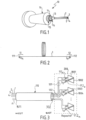
Figure 1 is a picture of a cross section of a submarine communication cable. -
Figure 2 is a schematic view of an optical fiber of the submarine communication cable offigure 1 . -
Figure 3 is a schematic view of a submarine communication cable connected to an optical submarine repeater. -
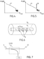
Figure 4 is the schematic of a trace of an Optical Time Domain Reflectometer (OTDR) when a measurement is performed on the optical fiber ofFigure 2 , in which is coupled an optical pulse having a wavelength different from the tagging wavelength of the optical fiber. -
Figure 5 is the schematic of a trace of an Optical Time Domain Reflectometer (OTDR) when a measurement is performed on the optical fiber ofFigure 2 , in which is coupled an optical pulse having the tagging wavelength of the optical fiber. -
Figure 6 is a schematic representation of an end of a span of the optical fiber of theFigure 2 , for the case that a distributed Bragg grating reflector is formed directly in the fiber. -
Figure 7 is a schematic representation of an optical splitter/coupler configured to direct a portion of an incident tagging pulse from a candidate fiber to a reflector, and coupling a reflection of the pulse from the reflector back to the candidate fiber. - The description hereinbelow is directed to an optical communication cable in which one or more optical fibers are tagged for enabling the identification of the optical fibers. Although the example is directed to a submarine cable, the optical cable described below may be comprised in any kind of cable including, but not limited to, a terrestrial cable or a subsurface cable.
- With reference to
Figure 1 , acommunication cable 10, e.g. a submarine cable, will be described according to various embodiments. - The
optical communication cable 10 is a cable adapted to be laid on the sea bed between land-based stations to carry telecommunication signals across the sea between the land-based stations. For example, the land-based stations may be separated by an ocean. In such a case, the submarine communication cable is connected typically to optical submarine repeaters laid on the sea bed as well. - As represented, the
optical communication cable 10 comprises an optical cable comprising two pairs ofoptical fibers 1, 2, and 3, 4, the optical cable being arranged into a petroleum jelly inside analuminum tube 13. Theoptical communication cable 10 further comprises strandedsteel wires 14 arranged all around thealuminum tube 13. The strandedsteel wires 14 are wrapped withelectrical layer 15 of copper wires and the wholeoptical communication cable 10 further comprises apolyethylene sleeve 16 protecting against salted water and bumps. - The
electrical layer 15 is adapted to transmit electrical power to submarine repeaters and/or electrical communication signals from one end to another. - The pairs of
optical fibers 1, 2 and 3, 4 are adapted to transmit optical signals from one end to another. - A first
optical fiber 1 of the pair ofoptical fibers 1, 2 is adapted to transmit an optical signal in a direction from one end to another, e.g. east (W) to west (E), whereas a second optical fiber 2 of the pair ofoptical fiber 1, 2 is adapted to transmit an optical signal in the opposite direction, e.g. E to W. The same applies to the pair of optical fibers 3, 4. - With reference to
Figure 2 , theoptical fiber 1 will be further described, according to various embodiments. - The
optical fiber 1 comprises two ends 11 and 12. Theoptical fiber 1 includes a flexible silica fiber adapted to transmit an optical signal between the two ends 11 and 12.The optical signal may be carried by any wavelength in a defined bandwidth spectrum. The loops represented on theoptical fiber 1 schematically depicts that the span of theoptical fiber 1 is typically very long, for example is about 155 km. Theoptical fiber 1 may be a Conventional Single Mode Fiber (CSF fiber). - As represented, the
first end 11 of theoptical fiber 1 is equipped with a firstoptical reflector 111 and thesecond end 12 of the optical fiber 2 is equipped with a secondoptical reflector 112. The firstoptical reflector 111 is located near thefirst end 11. By "near", it is meant that thereflector 111 is physically coupled to a portion of theoptical fiber 1 that is outside any surrounding protective layers of a cable of which theoptical fiber 1 is a part. In the example embodiment of the cable 10 (Figure 1 ), the optical fibers 1-4 have been exposed by removal of thetube 13,wires 14 andsleeve 15. The firstoptical reflector 111 is located near the end of thefiber 1 when thereflector 111 is located in or coupled to a portion of thefiber 1 that is exposed after the removal of these layers. Thereflectors fiber 1 by a respective splitter/coupler, or as described in greater detail below may be formed within thefiber 1. - The first and the second
optical reflectors - Moreover, the
optical reflectors -
Figure 7 illustrates in greater detail the relationship between an optical fiber, e.g. thefiber 1, and an optical reflector, e.g. thereflector 112. A splitter/coupler 1120 diverts a portion of light received via thefiber 1 to thereflector 112. The splitter/coupler 1120 may be referred to for brevity ascoupler 1120 without loss of generality. Conversely, light reflected by theoptical reflector 112 is coupled by thecoupler 1120 to thefiber 1. Although not shown explicitly inFigure 2 and inFigure 3 below, thecoupler 1120 is presumed to be present unless otherwise described. Thereflector 112 may be a distributed Bragg grating (DBG) formed in an optical fiber or in a planar waveguide. Thereflector 112 is described in greater detail below with reference toFigure 6 . -
Figure 3 is a schematic view of anoptical communication cable 110 connected to anoptical submarine repeater 200, according to various embodiments. - As represented, the
optical communication cable 110 comprises a plurality of bundled pairs of optical fibers extending from oneend 301 of theoptical communication cable 110, e.g. west, to anotherend 302 of theoptical communication cable 110, e.g. east. - For the sake of simplicity, the optical fibers of a
first pair 101 and asecond pair 102 of optical fibers are similar to theoptical fibers 1, 2, 3 and 4 described with reference toFigures 1 and 2 . For the sake of simplicity, the optical fibers of thefirst pair 101 and of thesecond pair 102 are referenced by the same reference numbers as inFigures 1 and 2 . - In general an optical communication cable may have n optical fibers arranged as pairs. In an embodiment a tagging wavelength is assigned to each
optical fiber 1, 2, 3, 4 to n. In the illustrated embodiment an instance of the optical reflector is coupled to each of the n optical fibers at only one end, e.g. east, of theoptical communication cable 110. In other embodiments, an optical reflector may also be coupled to the optical fibers at the other end, e.g. west, of theoptical communication cable 110, as described for theoptical fiber 1 with reference toFigure 2 . The optical reflector coupled to a particular optical fiber reflects only the tagging wavelength assigned to that fiber. Moreover, the optical reflector is transparent to the spectrum of wavelengths of optical communication signals carried by that fiber. - Thus, for example, an
optical reflector 1121 of the firstoptical fiber 1 is adapted to reflect a tagging wavelength λ1. As described in greater detail below, the tagging wavelength λ1 may therefore be used as a tag for identifying the firstoptical fiber 1. - Stated more generally, an
optical reflector 112 i of an i th optical fiber is adapted to reflect a corresponding tagging wavelength λi, wherein none of the optical fibers share a same tagging wavelength. Therefore each tagging wavelength λi may be used to as a tag for identifying the corresponding i th optical fiber, wherein i is an integer from 1 to n. - The
optical submarine repeater 200 comprisesoptical amplifiers optical fibres 1, 2, 3, 4 etc. - As previously described with reference to
Figure 1 , a first optical fiber of a pair of optical fiber is adapted to transmit a first optical signal in a direction from one end to another, e.g. west to east, whereas a second optical fiber of the pair of optical fiber is adapted to transmit a second optical signal in the opposite direction, e.g. east to west. - Therefore each optical fiber of each pair of optical fibers may be connected to a corresponding pair of optical amplifiers at the east end of the
optical communication cable 110, one configured to receive an eastbound signal from one fiber of the pair, and one configured to transmit a westbound signal to the other fiber of the pair. Optical amplifiers may be similarly located at the opposite, e.g. west, end of theoptical communication cable 110. - More precisely, a first optical fiber, for example
optical fiber 1, of a pair of optical fibers, for example the pair ofoptical fibers 101, is connected to a first optical amplifier, for exampleoptical amplifier 1001, of a pair of optical amplifiers, for example the pair comprising theoptical amplifiers - A second optical fiber, for example optical fiber 2, of the pair of optical fibers is connected to a second optical amplifier, for example
optical amplifier 1002. The second optical amplifier is configured to amplify an optical signal to be transmitted to the second optical fiber. - The two optical amplifiers of a pair of optical amplifiers are adapted to amplify optical signals received in two opposite directions, e.g. west to east and east to west.
- For each
optical fiber 1, 2, 3, 4 etc., the corresponding optical reflectors are used as tagging devices for tagging the optical fiber in the method described below. - The method to identify the
optical fiber 1 comprises an Optical Time Domain Reflectometer (OTDR) measurement using a tag-identifying optical pulse that includes the tagging wavelength of the optical fiber. - For example, an operator may couple the tag-identifying optical pulse into an optical fiber to be identified, and measure a reflection of the optical pulse using the OTDR measurement device. More specifically, for example, the operator may couple a light pulse including λ1 into the
optical fiber 1 at an input end, e.g. the left (west) side ofFigure 3 . After propagating east the length of thefiber 1, a portion of the signal is diverted by the coupler 1120 (Figure 7 ) to theoptical reflector 1121. Light in the pulse having the wavelength λ1 is reflected by theoptical reflector 1121, and coupled back to thefiber 1 and propagates back to the input (west) end of the fiber. The portion of the signal not diverted by thecoupler 1120 will propagate to theamplifier 1001. If the pulse only includes light at λ1, and is coupled to another one of the optical fibers, the pulse will not be reflected by the optical reflector coupled to that optical fiber. Thusoptical fiber 1 may be uniquely identified among the various optical fibers. Of course, this principle may be extended to identify each of the other optical fibers using corresponding pulses of λ1, λ2, λ3,... λn. Optionally, the optical coupler and reflector may be omitted from one of the optical fibers, as this optical fiber may be known after the other fibers are identified. - The two cases are described with reference to
Figures 4 and 5 with the example ofoptical fiber 1. -
Figure 4 schematically represents a measured OTDR trace of a tag identifying optical pulse having any tagging wavelength other than λ1 in theoptical fiber 1, e.g. λ2. As pictured, the OTDR measure of a tag identifying optical pulse having the tagging wavelength λ2 shows no reflection peak at the end of theoptical fiber 1.Figure 5 schematically represents a measured OTDR trace of a tag identifying optical pulse having a tagging wavelength λ1 in theoptical fiber 1. In this case the OTDR trace shows areflection peak 50 corresponding to the round-trip time between launching the optical pulse at the input (e.g. west) end of theoptical fiber 1, and the return of the pulse reflected by thereflector 112. - The
slopes 41, 51 pictured onFigures 4 and 5 show the absorption of theoptical fiber 1, respectively for the tagging wavelength λ2 and tagging wavelength λ1. - Several useful advantages of the described method are apparent. First, coloring of the optical fibers for the purpose of fiber identification may be eliminated. Second, even very long span optical fibers, for example 155 km long optical fibers, can be tagged and identified in a very short time, for example in less than one minute. Third, the method does not impact the assembly process operation. Finally, an optical fiber may be easily identified in a reparation process following an accidental cut of the optical cable. For example, an accidental cut of the optical cable of the submarine cable may be caused by a trawler.
- By detecting the
reflection peak 50 only when coupling theoptical fiber 1 with a tag identifying optical pulse having the tagging wavelength λ1, the operator deduces that the optical fiber to determined is theoptical fiber 1. - Similarly, OTDR traces will show a reflection peak for the optical fiber 2 when coupling with a tag-identifying optical pulse having a tagging wavelength λ2 and so on for the other fibers.
- A method for determining a particular tagged optical fiber in a set of candidate optical fibers of an optical cable, e.g. a submarine communication cable, is described below. The tagged optical fiber is uniquely associated with a corresponding tagging optical wavelength.
- The operator selects a candidate optical fiber in the set of candidate optical fibers.
- The operator launches an OTDR measurement on the selected candidate optical fiber at the tagging wavelength corresponding to the tagged optical fiber.
- If the OTDR trace shows a reflection peak at the end of the candidate optical fiber, the candidate optical fiber is determined to be the tagged optical fiber.
- If the OTDR trace does not show any reflection peak at the end of the candidate optical fiber, the operator selects a new candidate optical fiber and launches a new OTDR measurement at the tagging wavelength, until an OTDR trace of a candidate optical fiber shows the reflection peak.
- The method above described is very useful to identify the optical fibers in any optical cable, for example in a submarine communication cable, namely during assembly process of the submarine communication cable or during a submarine communication cable repair.
- The last optical fiber, which optionally has no reflector, may be identified in the submarine communication cable by the fact that no reflection peak is observed when a pulse of light of any tagging wavelength is sent in the last optical fiber.
- The reflectors tagging each
optical fiber 1, 2, 3, 4 etc. may each be a DBG reflector coupled to the corresponding optical fiber by a splitter/coupler. In this case, the DBG may be formed in a planar optical waveguide, or may be formed in a short optical fiber connected to the splitter/coupler. A DBG formed in an optical fiber is sometimes referred to as a fiber Bragg grating (FBG). In some alternate embodiments the FBG may be formed directly in the corresponding optical fiber, in which cases the splitter/coupler is not needed. In such embodiments, wavelengths other than the reflected wavelength, e.g. communication signals, will pass through the FBG to the amplifier connected to the optical fiber. An FBG reflector formed within an optical fiber is defined for the purpose of this discussion and the claims as being coupled to the optical fiber in which it is formed. -
Figure 6 shows an example of a FBG that may be used in some embodiments. An optical fiber comprises a core having a refractive index n2 and a cladding having a refractive index n1. A refractive index no represents a buffer, jacket or air. - A periodic variation of the refractive index of the core has been created within the core using methods well-known to those skilled in the art. The period of the variation is referenced on the
Figure 6 by letter L. The refractive index of the core alternates from a first refractive index n2 to a second refractive index n3 on each period L. This periodic variation in the refractive index of the core generates a wavelength-specific dielectric mirror which selectively reflects a corresponding one of the tagging wavelengths while passing other wavelengths. - In some other embodiments, one or more reflectors may include an optical ring resonator structure, such as may be formed on a planar optical device. Such resonators may be used, e.g. when the reflector is coupled to the associated optical fiber via a splitter/coupler. Reflectors based on a ring resonator may provide an advantage in some cases by providing tunability of the reflection wavelength. It is expected that such reflectors may be more easily implemented in terrestrial cable environments, but embodiments are not limited to such implementations. Any other well-known method of tuning may be used, depending on the DBG implementation, e.g. thermal control or fiber tension.
- Embodiments of the invention are not limited to those described above. The appended claims are to be construed as embodying all modification and alternative constructions that may be occurred to one skilled in the art, which fairly fall within the basic teaching here, set forth. For example, the tagging wavelengths may be selected out-of-band of the spectrum amplified by the
amplifiers - The use of the verb "to comprise" or "to include" and its conjugations does not exclude the presence of elements or steps other than those stated in a claim. Furthermore, the use of the article "a" or "an" preceding an element or step does not exclude the presence of a plurality of such elements or steps.
- In the claims, any reference signs placed between parentheses shall not be construed as limiting the scope of the claims.
Claims (10)
- An optical cable (110) for transmitting optical signals, the optical cable (110) comprising an optical cable span having a first end and a second end, said optical cable span including a first optical fiber (1) and a second optical fiber (2); the first and second optical fibers extending from the first end of the optical cable span to the second end of the optical cable span, wherein said first and second optical fibers are configured to propagate optical communications signals in a first optical communication band, the optical cable (110) comprising:a first optical reflector (112) optically coupled to said first optical fiber near the first end (302) of said optical cable span and configured to reflect a first tagging wavelength (λ1) of light; anda second optical reflector (112) optically coupled to said second optical fiber near said first end (302) of said optical cable span, wherein at least one of the optical reflectors comprises a distributed Bragg grating (DBG),characterized in that the second optical reflector is configured to reflect a second different tagging wavelength (λ2) of light,the DBG being formed in an optical fiber core, , and the optical reflectors being transparent to the first optical communication band, wherein said first and second tagging wavelengths are located within a second different optical communication band.
- An optical cable according to claim 1, wherein said first optical reflector is optically coupled to said first optical fiber via a first optical splitter/coupler (1120), and said second optical reflector is optically coupled to said second optical fiber via a second optical splitter/coupler (1120).
- An optical cable according to claim 1, wherein the optical fibers are not color-coded.
- An optical cable according to claim 1, comprising a third optical fiber, wherein the number of optical reflectors is fewer than the number of optical fibers.
- An optical cable according to claim 1, wherein one or more of the optical reflectors are tunable in reflection wavelength.
- An optical cable according to any one of claims 1 to 5, further comprising a third optical reflector optically coupled to said first optical fiber near a second end (12) of said span, and a fourth optical reflector optically coupled to said second optical fiber near said second end (12) of said span.
- Use of an optical cable according to any one of claims 1 to 6, wherein said optical cable is at least partially submerged under water.
- A method for identifying tagged optical fibers (1) in an optical cable (110) including a set of candidate optical fibers (1, 2, 3, 4, n) that extend from a first end of the optical cable to a second end of the optical cable, the method comprising:- providing a set of candidate optical fibers (1, 2, 3, 4, n), wherein a first optical reflector (112) is coupled to a first one of said optical fibers near the first end (302) of the optical cable, the first optical reflector (112) being configured to reflect a first tagging wavelength (λ1) at the first end (302), wherein a second optical reflector (112) is coupled to a second one of said optical fibers near the one end (302) of the optical cable, the second optical reflector (112) being configured to reflect a second different tagging wavelength (λ2) at the one end (302), at least one of the first and second optical reflectors comprising a distributed Bragg grating (DBG), the DBG being formed in an optical fiber core, said candidate optical fibers being configured to carry optical communication signals in a first optical communication band, and said first and second tagging wavelengths being located within a second different optical communication band,- directing the first optical tagging pulse including said first tagging wavelength to the first one of said optical fibers at the second end (301) of the optical cable , and- receiving a reflection of said first optical tagging pulse at said second end,- directing a second optical tagging pulse including said second tagging wavelength to said second one of said optical fibers at the second end (301) of the optical cable, and- receiving a reflection of said second optical tagging pulse at said second end.
- A method according to claim 8, wherein the candidate optical fibers are not color-coded.
- A method according any of claims 8 to 9, wherein said candidate optical fibers are located within a submarine optical cable.
Priority Applications (1)
| Application Number | Priority Date | Filing Date | Title |
|---|---|---|---|
| EP17306168.0A EP3454481B1 (en) | 2017-09-11 | 2017-09-11 | Submarine communication cable and method for identifying an optical fiber |
Applications Claiming Priority (1)
| Application Number | Priority Date | Filing Date | Title |
|---|---|---|---|
| EP17306168.0A EP3454481B1 (en) | 2017-09-11 | 2017-09-11 | Submarine communication cable and method for identifying an optical fiber |
Publications (2)
| Publication Number | Publication Date |
|---|---|
| EP3454481A1 EP3454481A1 (en) | 2019-03-13 |
| EP3454481B1 true EP3454481B1 (en) | 2024-11-06 |
Family
ID=59887178
Family Applications (1)
| Application Number | Title | Priority Date | Filing Date |
|---|---|---|---|
| EP17306168.0A Active EP3454481B1 (en) | 2017-09-11 | 2017-09-11 | Submarine communication cable and method for identifying an optical fiber |
Country Status (1)
| Country | Link |
|---|---|
| EP (1) | EP3454481B1 (en) |
Families Citing this family (2)
| Publication number | Priority date | Publication date | Assignee | Title |
|---|---|---|---|---|
| CN116719135A (en) * | 2023-06-08 | 2023-09-08 | 烽火通信科技股份有限公司 | Identifiable optical cable |
| CN119070896B (en) * | 2024-08-14 | 2025-11-28 | 国网安徽省电力有限公司淮北供电公司 | Optical cable fault position diagnosis system |
Family Cites Families (3)
| Publication number | Priority date | Publication date | Assignee | Title |
|---|---|---|---|---|
| FR2837288B1 (en) * | 2002-03-14 | 2004-11-05 | Cit Alcatel | METHOD FOR IDENTIFYING OPTICAL FIBERS IN A CABLE |
| EP1952561B1 (en) * | 2005-10-24 | 2018-04-04 | Exfo Inc. | Method and apparatus for identification of multiple fibers using an otdr |
| US9831943B2 (en) * | 2013-12-17 | 2017-11-28 | Neptune Subsea Ip Limited | Repeater OTDR using repeater based raman pumps |
-
2017
- 2017-09-11 EP EP17306168.0A patent/EP3454481B1/en active Active
Also Published As
| Publication number | Publication date |
|---|---|
| EP3454481A1 (en) | 2019-03-13 |
Similar Documents
| Publication | Publication Date | Title |
|---|---|---|
| US12235139B2 (en) | Cable system | |
| JP5170909B2 (en) | Optical transmission system and multi-core optical fiber | |
| JP2022191168A (en) | Extending dynamic acoustic sensing range and localization in undersea cables using loopbacks | |
| EP4160941A1 (en) | Distributed sensing and monitoring using amplified optical links | |
| US20050244116A1 (en) | Cables and cable installations | |
| EP3205033B1 (en) | Apparatus for optical time-domain reflectometry | |
| Mori et al. | Applicability of standard cladding diameter multi-core fiber cables for terrestrial field | |
| EP3454481A1 (en) | Submarine communication cable and method for identifying an optical fiber | |
| US20090154870A1 (en) | Optical Fiber Sensor Connected To Optical Fiber Communication Line | |
| Yamamoto | Practical aspects of G. 654. E fibers for terrestrial long haul transmission | |
| US12571673B2 (en) | Multi-span optical fiber das system with amplified-filtered loopback (AFLB) | |
| Downie et al. | O-band transmission over high-cutoff G. 654. C fiber | |
| US7835604B2 (en) | Fiber Bragg grating element | |
| André et al. | Evaluation of the fuse effect propagation in networks infrastructures with different types of fibers | |
| Yamamoto et al. | Low loss optical fibers for terrestrial long-haul networks, PureAdvance | |
| Nakamura et al. | Impact of Optical Loopback on Backward Crosstalk and Fault Localisation in Multi-Core Fiber Submarine Systems | |
| Kawaguchi et al. | Behavior of Inter-core Crosstalk of Two-core Fiber in Submarine Cable | |
| US20250110281A1 (en) | Device for transmitting data from solid core optical fibers to a hollow core fiber and method of use thereof | |
| Imada et al. | Applicability of Homogeneous/Heterogeneous Multi-core Fibers for Submarine Cables | |
| US20250266904A1 (en) | Method for Fault Localization in an Optical Network | |
| Nakamura et al. | Identification of loss factors by evaluating backscattered modal loss ratio obtained with 1-μm-band mode-detection OTDR | |
| Takahashi et al. | Brillouin Gain Spectral Manipulation by Modal Brillouin Interaction for FMF Measurement | |
| JP2005221388A (en) | Optical fiber communication line test system and method | |
| Nakamura et al. | Identification of loss factors by evaluating backscattered modal loss ratio obtained with 1-µm-band mode-detection OTDR | |
| Sasaki et al. | Combined fiber optic network for communication and measurement using a hetero-core spliced fiber optic sensor |
Legal Events
| Date | Code | Title | Description |
|---|---|---|---|
| PUAI | Public reference made under article 153(3) epc to a published international application that has entered the european phase |
Free format text: ORIGINAL CODE: 0009012 |
|
| STAA | Information on the status of an ep patent application or granted ep patent |
Free format text: STATUS: THE APPLICATION HAS BEEN PUBLISHED |
|
| AK | Designated contracting states |
Kind code of ref document: A1 Designated state(s): AL AT BE BG CH CY CZ DE DK EE ES FI FR GB GR HR HU IE IS IT LI LT LU LV MC MK MT NL NO PL PT RO RS SE SI SK SM TR |
|
| AX | Request for extension of the european patent |
Extension state: BA ME |
|
| STAA | Information on the status of an ep patent application or granted ep patent |
Free format text: STATUS: REQUEST FOR EXAMINATION WAS MADE |
|
| 17P | Request for examination filed |
Effective date: 20190913 |
|
| RBV | Designated contracting states (corrected) |
Designated state(s): AL AT BE BG CH CY CZ DE DK EE ES FI FR GB GR HR HU IE IS IT LI LT LU LV MC MK MT NL NO PL PT RO RS SE SI SK SM TR |
|
| STAA | Information on the status of an ep patent application or granted ep patent |
Free format text: STATUS: EXAMINATION IS IN PROGRESS |
|
| 17Q | First examination report despatched |
Effective date: 20210218 |
|
| GRAP | Despatch of communication of intention to grant a patent |
Free format text: ORIGINAL CODE: EPIDOSNIGR1 |
|
| STAA | Information on the status of an ep patent application or granted ep patent |
Free format text: STATUS: GRANT OF PATENT IS INTENDED |
|
| INTG | Intention to grant announced |
Effective date: 20240607 |
|
| GRAS | Grant fee paid |
Free format text: ORIGINAL CODE: EPIDOSNIGR3 |
|
| GRAA | (expected) grant |
Free format text: ORIGINAL CODE: 0009210 |
|
| STAA | Information on the status of an ep patent application or granted ep patent |
Free format text: STATUS: THE PATENT HAS BEEN GRANTED |
|
| AK | Designated contracting states |
Kind code of ref document: B1 Designated state(s): AL AT BE BG CH CY CZ DE DK EE ES FI FR GB GR HR HU IE IS IT LI LT LU LV MC MK MT NL NO PL PT RO RS SE SI SK SM TR |
|
| REG | Reference to a national code |
Ref country code: GB Ref legal event code: FG4D |
|
| REG | Reference to a national code |
Ref country code: CH Ref legal event code: EP |
|
| REG | Reference to a national code |
Ref country code: DE Ref legal event code: R096 Ref document number: 602017085907 Country of ref document: DE |
|
| REG | Reference to a national code |
Ref country code: IE Ref legal event code: FG4D |
|
| REG | Reference to a national code |
Ref country code: LT Ref legal event code: MG9D |
|
| REG | Reference to a national code |
Ref country code: NL Ref legal event code: MP Effective date: 20241106 |
|
| PG25 | Lapsed in a contracting state [announced via postgrant information from national office to epo] |
Ref country code: IS Free format text: LAPSE BECAUSE OF FAILURE TO SUBMIT A TRANSLATION OF THE DESCRIPTION OR TO PAY THE FEE WITHIN THE PRESCRIBED TIME-LIMIT Effective date: 20250306 Ref country code: HR Free format text: LAPSE BECAUSE OF FAILURE TO SUBMIT A TRANSLATION OF THE DESCRIPTION OR TO PAY THE FEE WITHIN THE PRESCRIBED TIME-LIMIT Effective date: 20241106 Ref country code: PT Free format text: LAPSE BECAUSE OF FAILURE TO SUBMIT A TRANSLATION OF THE DESCRIPTION OR TO PAY THE FEE WITHIN THE PRESCRIBED TIME-LIMIT Effective date: 20250306 |
|
| PG25 | Lapsed in a contracting state [announced via postgrant information from national office to epo] |
Ref country code: FI Free format text: LAPSE BECAUSE OF FAILURE TO SUBMIT A TRANSLATION OF THE DESCRIPTION OR TO PAY THE FEE WITHIN THE PRESCRIBED TIME-LIMIT Effective date: 20241106 Ref country code: NL Free format text: LAPSE BECAUSE OF FAILURE TO SUBMIT A TRANSLATION OF THE DESCRIPTION OR TO PAY THE FEE WITHIN THE PRESCRIBED TIME-LIMIT Effective date: 20241106 |
|
| REG | Reference to a national code |
Ref country code: AT Ref legal event code: MK05 Ref document number: 1740530 Country of ref document: AT Kind code of ref document: T Effective date: 20241106 |
|
| PG25 | Lapsed in a contracting state [announced via postgrant information from national office to epo] |
Ref country code: BG Free format text: LAPSE BECAUSE OF FAILURE TO SUBMIT A TRANSLATION OF THE DESCRIPTION OR TO PAY THE FEE WITHIN THE PRESCRIBED TIME-LIMIT Effective date: 20241106 |
|
| PG25 | Lapsed in a contracting state [announced via postgrant information from national office to epo] |
Ref country code: ES Free format text: LAPSE BECAUSE OF FAILURE TO SUBMIT A TRANSLATION OF THE DESCRIPTION OR TO PAY THE FEE WITHIN THE PRESCRIBED TIME-LIMIT Effective date: 20241106 |
|
| PG25 | Lapsed in a contracting state [announced via postgrant information from national office to epo] |
Ref country code: NO Free format text: LAPSE BECAUSE OF FAILURE TO SUBMIT A TRANSLATION OF THE DESCRIPTION OR TO PAY THE FEE WITHIN THE PRESCRIBED TIME-LIMIT Effective date: 20250206 |
|
| PG25 | Lapsed in a contracting state [announced via postgrant information from national office to epo] |
Ref country code: AT Free format text: LAPSE BECAUSE OF FAILURE TO SUBMIT A TRANSLATION OF THE DESCRIPTION OR TO PAY THE FEE WITHIN THE PRESCRIBED TIME-LIMIT Effective date: 20241106 Ref country code: LV Free format text: LAPSE BECAUSE OF FAILURE TO SUBMIT A TRANSLATION OF THE DESCRIPTION OR TO PAY THE FEE WITHIN THE PRESCRIBED TIME-LIMIT Effective date: 20241106 Ref country code: GR Free format text: LAPSE BECAUSE OF FAILURE TO SUBMIT A TRANSLATION OF THE DESCRIPTION OR TO PAY THE FEE WITHIN THE PRESCRIBED TIME-LIMIT Effective date: 20250207 |
|
| PG25 | Lapsed in a contracting state [announced via postgrant information from national office to epo] |
Ref country code: PL Free format text: LAPSE BECAUSE OF FAILURE TO SUBMIT A TRANSLATION OF THE DESCRIPTION OR TO PAY THE FEE WITHIN THE PRESCRIBED TIME-LIMIT Effective date: 20241106 |
|
| PG25 | Lapsed in a contracting state [announced via postgrant information from national office to epo] |
Ref country code: RS Free format text: LAPSE BECAUSE OF FAILURE TO SUBMIT A TRANSLATION OF THE DESCRIPTION OR TO PAY THE FEE WITHIN THE PRESCRIBED TIME-LIMIT Effective date: 20250206 |
|
| PG25 | Lapsed in a contracting state [announced via postgrant information from national office to epo] |
Ref country code: SM Free format text: LAPSE BECAUSE OF FAILURE TO SUBMIT A TRANSLATION OF THE DESCRIPTION OR TO PAY THE FEE WITHIN THE PRESCRIBED TIME-LIMIT Effective date: 20241106 |
|
| PG25 | Lapsed in a contracting state [announced via postgrant information from national office to epo] |
Ref country code: DK Free format text: LAPSE BECAUSE OF FAILURE TO SUBMIT A TRANSLATION OF THE DESCRIPTION OR TO PAY THE FEE WITHIN THE PRESCRIBED TIME-LIMIT Effective date: 20241106 |
|
| PG25 | Lapsed in a contracting state [announced via postgrant information from national office to epo] |
Ref country code: EE Free format text: LAPSE BECAUSE OF FAILURE TO SUBMIT A TRANSLATION OF THE DESCRIPTION OR TO PAY THE FEE WITHIN THE PRESCRIBED TIME-LIMIT Effective date: 20241106 |
|
| PG25 | Lapsed in a contracting state [announced via postgrant information from national office to epo] |
Ref country code: RO Free format text: LAPSE BECAUSE OF FAILURE TO SUBMIT A TRANSLATION OF THE DESCRIPTION OR TO PAY THE FEE WITHIN THE PRESCRIBED TIME-LIMIT Effective date: 20241106 |
|
| PG25 | Lapsed in a contracting state [announced via postgrant information from national office to epo] |
Ref country code: SK Free format text: LAPSE BECAUSE OF FAILURE TO SUBMIT A TRANSLATION OF THE DESCRIPTION OR TO PAY THE FEE WITHIN THE PRESCRIBED TIME-LIMIT Effective date: 20241106 |
|
| PG25 | Lapsed in a contracting state [announced via postgrant information from national office to epo] |
Ref country code: CZ Free format text: LAPSE BECAUSE OF FAILURE TO SUBMIT A TRANSLATION OF THE DESCRIPTION OR TO PAY THE FEE WITHIN THE PRESCRIBED TIME-LIMIT Effective date: 20241106 |
|
| PG25 | Lapsed in a contracting state [announced via postgrant information from national office to epo] |
Ref country code: IT Free format text: LAPSE BECAUSE OF FAILURE TO SUBMIT A TRANSLATION OF THE DESCRIPTION OR TO PAY THE FEE WITHIN THE PRESCRIBED TIME-LIMIT Effective date: 20241106 |
|
| REG | Reference to a national code |
Ref country code: DE Ref legal event code: R097 Ref document number: 602017085907 Country of ref document: DE |
|
| PG25 | Lapsed in a contracting state [announced via postgrant information from national office to epo] |
Ref country code: SE Free format text: LAPSE BECAUSE OF FAILURE TO SUBMIT A TRANSLATION OF THE DESCRIPTION OR TO PAY THE FEE WITHIN THE PRESCRIBED TIME-LIMIT Effective date: 20241106 |
|
| PLBE | No opposition filed within time limit |
Free format text: ORIGINAL CODE: 0009261 |
|
| STAA | Information on the status of an ep patent application or granted ep patent |
Free format text: STATUS: NO OPPOSITION FILED WITHIN TIME LIMIT |
|
| 26N | No opposition filed |
Effective date: 20250807 |
|
| PGFP | Annual fee paid to national office [announced via postgrant information from national office to epo] |
Ref country code: GB Payment date: 20250731 Year of fee payment: 9 |
|
| PGFP | Annual fee paid to national office [announced via postgrant information from national office to epo] |
Ref country code: FR Payment date: 20250808 Year of fee payment: 9 |
|
| REG | Reference to a national code |
Ref country code: CH Ref legal event code: H13 Free format text: ST27 STATUS EVENT CODE: U-0-0-H10-H13 (AS PROVIDED BY THE NATIONAL OFFICE) Effective date: 20260504 |