EP3454473A1 - Nfc ring - Google Patents
Nfc ring Download PDFInfo
- Publication number
- EP3454473A1 EP3454473A1 EP17190052.5A EP17190052A EP3454473A1 EP 3454473 A1 EP3454473 A1 EP 3454473A1 EP 17190052 A EP17190052 A EP 17190052A EP 3454473 A1 EP3454473 A1 EP 3454473A1
- Authority
- EP
- European Patent Office
- Prior art keywords
- nfc
- ring
- processing unit
- nfc ring
- functions
- Prior art date
- Legal status (The legal status is an assumption and is not a legal conclusion. Google has not performed a legal analysis and makes no representation as to the accuracy of the status listed.)
- Granted
Links
Images


Classifications
-
- G—PHYSICS
- G06—COMPUTING OR CALCULATING; COUNTING
- G06K—GRAPHICAL DATA READING; PRESENTATION OF DATA; RECORD CARRIERS; HANDLING RECORD CARRIERS
- G06K19/00—Record carriers for use with machines and with at least a part designed to carry digital markings
- G06K19/06—Record carriers for use with machines and with at least a part designed to carry digital markings characterised by the kind of the digital marking, e.g. shape, nature, code
- G06K19/067—Record carriers with conductive marks, printed circuits or semiconductor circuit elements, e.g. credit or identity cards also with resonating or responding marks without active components
- G06K19/07—Record carriers with conductive marks, printed circuits or semiconductor circuit elements, e.g. credit or identity cards also with resonating or responding marks without active components with integrated circuit chips
- G06K19/077—Constructional details, e.g. mounting of circuits in the carrier
- G06K19/07749—Constructional details, e.g. mounting of circuits in the carrier the record carrier being capable of non-contact communication, e.g. constructional details of the antenna of a non-contact smart card
- G06K19/07758—Constructional details, e.g. mounting of circuits in the carrier the record carrier being capable of non-contact communication, e.g. constructional details of the antenna of a non-contact smart card arrangements for adhering the record carrier to further objects or living beings, functioning as an identification tag
- G06K19/07762—Constructional details, e.g. mounting of circuits in the carrier the record carrier being capable of non-contact communication, e.g. constructional details of the antenna of a non-contact smart card arrangements for adhering the record carrier to further objects or living beings, functioning as an identification tag the adhering arrangement making the record carrier wearable, e.g. having the form of a ring, watch, glove or bracelet
-
- G—PHYSICS
- G06—COMPUTING OR CALCULATING; COUNTING
- G06K—GRAPHICAL DATA READING; PRESENTATION OF DATA; RECORD CARRIERS; HANDLING RECORD CARRIERS
- G06K19/00—Record carriers for use with machines and with at least a part designed to carry digital markings
- G06K19/06—Record carriers for use with machines and with at least a part designed to carry digital markings characterised by the kind of the digital marking, e.g. shape, nature, code
- G06K19/067—Record carriers with conductive marks, printed circuits or semiconductor circuit elements, e.g. credit or identity cards also with resonating or responding marks without active components
- G06K19/07—Record carriers with conductive marks, printed circuits or semiconductor circuit elements, e.g. credit or identity cards also with resonating or responding marks without active components with integrated circuit chips
- G06K19/077—Constructional details, e.g. mounting of circuits in the carrier
- G06K19/07749—Constructional details, e.g. mounting of circuits in the carrier the record carrier being capable of non-contact communication, e.g. constructional details of the antenna of a non-contact smart card
- G06K19/07773—Antenna details
-
- H—ELECTRICITY
- H04—ELECTRIC COMMUNICATION TECHNIQUE
- H04B—TRANSMISSION
- H04B5/00—Near-field transmission systems, e.g. inductive or capacitive transmission systems
- H04B5/20—Near-field transmission systems, e.g. inductive or capacitive transmission systems characterised by the transmission technique; characterised by the transmission medium
-
- H—ELECTRICITY
- H04—ELECTRIC COMMUNICATION TECHNIQUE
- H04B—TRANSMISSION
- H04B5/00—Near-field transmission systems, e.g. inductive or capacitive transmission systems
- H04B5/40—Near-field transmission systems, e.g. inductive or capacitive transmission systems characterised by components specially adapted for near-field transmission
- H04B5/48—Transceivers
-
- H—ELECTRICITY
- H04—ELECTRIC COMMUNICATION TECHNIQUE
- H04B—TRANSMISSION
- H04B5/00—Near-field transmission systems, e.g. inductive or capacitive transmission systems
- H04B5/70—Near-field transmission systems, e.g. inductive or capacitive transmission systems specially adapted for specific purposes
-
- A—HUMAN NECESSITIES
- A44—HABERDASHERY; JEWELLERY
- A44C—PERSONAL ADORNMENTS, e.g. JEWELLERY; COINS
- A44C9/00—Finger-rings
- A44C9/0053—Finger-rings having special functions
Definitions
- NFC rings are rings that include an NFC chip and an NFC antenna.
- NFC rings may be used, for example, to unlock an NFC-enabled mobile device or another object (e.g., a vehicle or a door), to authorize certain transactions such as fare payments, to share data with other devices, and to start certain applications with custom settings.
- NFC rings are often not very flexible, in the sense that their functionality cannot be changed very easily.
- a near field communication (NFC) ring comprising a processing unit and one or more rotatable components, wherein said processing unit is configured to perform one or more predefined functions in response to one or more predefined rotations of said components.
- NFC near field communication
- one of said components is an outer portion of said NFC ring, said outer portion being arranged to rotate with respect to an inner portion of said NFC ring.
- the processing unit is configured to determine an angle of rotation between the outer portion and the inner portion, and to select one or more functions in dependence on said angle.
- said angle of rotation falls within an angle range associated with said one or more functions.
- the processing unit is configured to determine said angle of rotation by comparing a field dampening effect caused by the rotation with one or more stored reference values.
- said reference values are stored in a memory unit of an NFC chip of said NFC ring.
- the memory is an electrically erasable programmable read-only memory.
- the NFC ring further comprises a visual aid for showing the angle of rotation to a user.
- one of said components is a recoiling spring equipped with a sensor.
- the processing unit is configured to determine a sequence of clockwise and anticlockwise rotations of the recoiling spring, and to select one or more functions in dependence on said sequence.
- one of said functions comprises disabling the NFC ring.
- a method of operating a near field communication (NFC) ring comprising a processing unit and one or more rotatable components, wherein said processing unit performs one or more predefined functions in response to one or more predefined rotations of said components.
- NFC near field communication
- a computer program comprising non-transient executable instructions that, when executed by a processing unit, carry out or control a method of the kind set forth.
- a non-transitory computer-readable medium comprises said computer program.
- Fig. 1A shows an example of an NFC system 100.
- the NFC system 100 comprises an NFC ring 102 that is configured to carry out near field communication (NFC) with an NFC reader 104.
- the NFC reader 104 may, for example, be a standalone device or a device embedded in a mobile device.
- the NFC ring 102 includes an NFC chip (not shown) and an NFC antenna (not shown).
- the NFC ring 102 may be used, for example, to unlock an NFC-enabled mobile device or another object, to authorize certain transactions such as fare payments, to share data with other devices, and to start certain applications with custom settings.
- the NFC ring 102 may take the form of a material ring, i.e. a small circular band worn on a finger as an ornament or a token of, for example, marriage, engagement, or authority. As mentioned above, the NFC ring 102 may not be very flexible, in the sense that its functionality cannot be changed very easily.
- Fig. 1B shows an example of an NFC ring.
- This NFC ring is marketed under the trademark NFC Ring ®.
- an NFC ring comprising a processing unit and one or more rotatable components, wherein the processing unit is configured to perform one or more predefined functions in response to one or more rotations of said components.
- the functionality of the NFC ring can be changed quickly and easily.
- Fig. 2 shows an illustrative embodiment of an NFC ring 200.
- the NFC ring 200 comprises one or more rotatable components 202.
- the NFC ring 200 comprises a processing unit 204.
- the processing unit 204 is configured to perform one or more predefined functions in response to one or more rotations of said components 202.
- a first function may comprise unlocking an NFC-enabled mobile device
- a second function may comprise unlocking a door
- a third function may comprise authorizing a certain transaction, etc.
- Fig. 3 shows an illustrative embodiment of an operating method 300.
- the NFC ring component or components 202 perform, at 302, one or more predefined rotations. These rotations may be initiated by a user, as will be shown with examples hereinbelow.
- the processing unit 204 performs one or more predefined functions in response to the predefined rotation or rotations of the components 202.
- the method 300 may be carried out or controlled by a computer program executed by the processing unit 204.
- Fig. 4 shows another illustrative embodiment of an NFC ring 400.
- the NFC ring 400 comprises an inner portion 402 (i.e., an inner ring or inner circle) and an outer portion 400 (i.e., an outer ring or outer circle).
- one of said components is an outer portion of said NFC ring, said outer portion being arranged to rotate with respect to an inner portion of said NFC ring.
- This embodiment which is shown in Fig. 4 , results in a practical and efficient implementation. More specifically, the outer ring or outer circle can slide over the inner ring or inner circle.
- the processing unit is configured to determine an angle of rotation between the outer portion 400 and the inner portion 402, and to select one or more functions in dependence on said angle.
- the angle of rotation is a suitable parameter which can easily be determined. For instance, as shown in Fig. 4 , the angle of rotation can be determined by measuring a field dampening effect caused by the rotation. More specifically, a rotation of the outer portion 400 with respect to the inner portion 402 causes that a specific field dampening material 406 - i.e., R1, R2, R3, or R4 - is brought into proximity of a field drop measuring sensor 408.
- the NFC chip may comprise a processing unit of the kind set forth. Furthermore, the NFC chip may read out the field dampening effect measured by the field drop measuring sensor 408, and may select one or more functions in dependence on the measured value provided by the field drop measuring sensor 408. More specifically, the field dampening effect may be determined by measuring, directly or indirectly, a capacitance increase or capacitance reduction which is caused by a different dielectric medium (i.e., field dampening material) coming into proximity of the sensor 408. The processing unit may select said functions by comparing the received measured value with one or more stored reference values, for example, and select the function or functions associated with the matching reference value.
- the angle of rotation falls within a range associated with said one or more functions.
- a range associated with said one or more functions For instance, in Fig. 4 , four angle ranges (not shown) may be defined, wherein each of the angle ranges comprises one of the field dampening materials 406.
- each angle range corresponds to a different field dampening effect.
- the circle formed by the ring may be split into predefined (e.g., equal) angle ranges. These angle ranges may be regarded as slices or pies. Each angle range may have a different field dampening effect. These effects may be pre-calibrated into a memory unit of the NFC chip, i.e. in the form of stored reference values.
- the processing unit may compare measured field dampening effects with stored reference values, and, in case of a match, select the corresponding function or functions.
- the memory unit is an electrically erasable programmable read-only memory (EEPROM).
- EEPROM electrically erasable programmable read-only memory
- the NFC ring 400 comprises a visual aid 410 to identify the option of rotation.
- the NFC ring 400 comprises a visual aid 410 that shows the angle of rotation to a user. In this way, the user may easily select a desired functionality.
- Fig. 5 shows a further illustrative embodiment of an NFC ring 500.
- the NFC ring 500 comprises two recoiling springs with a sensor 504, and an NFC chip 502.
- the NFC ring 500 comprises a display screen 506.
- one of the NFC ring components is a recoiling spring equipped with a sensor.
- This embodiment which is shown in Fig. 5 , is another practical and efficient implementation of a rotatable component.
- two recoiling springs 504 are shown as an example. The rotation of the spring or springs is measured by sensors attached to the springs.
- the measured value is provided to a processing unit (not shown) of the NFC chip 502, which compares said measured value with one or more stored reference values and selects one or more functions in dependence on the result of the comparison.
- the display screen 506 may be configured to show the selected function or functions.
- the processing unit is configured to determine a sequence of clockwise and anticlockwise rotations of the recoiling spring, and to select one or more functions in dependence on said sequence.
- one of said functions comprises disabling the NFC ring. In this way, the NFC ring can be temporarily disabled and easily reactivated by rotating the ring's component or components.
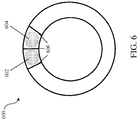
- Fig. 6 shows a further illustrative embodiment of an NFC ring 600.
- sensors may be attached to the recoiling springs 504 shown in Fig. 5 .
- These sensors may measure a capacitance increase or capacitance reduction of a first capacitor 602 and a second capacitor 604.
- the first and second capacitor 604 may be formed by dielectric materials between metal plates 606. Two of said plates 606 may be stationary and one of said plates 606 may be movable. Alternatively, one of said plates 606 may be stationary and two of said plates 606 may be movable.
- a deformation of a spring causes the movable plate or plates to move with respect to the stationary plate or plates, such that one of the dielectric materials is compressed and the other dielectric material is expanded.
- the resulting capacitance changes of the first capacitor 602 and second capacitor 604 can be measured by any suitable sensor.
- the skilled person will appreciate that other sensors can equally well be applied to the embodiment shown in Fig. 5 .
- the systems and methods described herein may at least partly be embodied by a computer program or a plurality of computer programs, which may exist in a variety of forms both active and inactive in a single computer system or across multiple computer systems.
- they may exist as software program(s) comprised of program instructions in source code, object code, executable code or other formats for performing some of the steps.
- Any of the above may be embodied on a computer-readable medium, which may include storage devices and signals, in compressed or uncompressed form.
- the term “mobile device” refers to any type of portable electronic device, including a cellular telephone, a Personal Digital Assistant (PDA), smartphone, tablet etc.
- the term “computer” refers to any electronic device comprising a processor, such as a general-purpose central processing unit (CPU), a specific-purpose processor or a microcontroller.
- CPU central processing unit
- a computer is capable of receiving data (an input), of performing a sequence of predetermined operations thereupon, and of producing thereby a result in the form of information or signals (an output).
- the term “computer” will mean either a processor in particular or more generally a processor in association with an assemblage of interrelated elements contained within a single case or housing.
- processor or “processing unit” refers to a data processing circuit that may be a microprocessor, a co-processor, a microcontroller, a microcomputer, a central processing unit, a field programmable gate array (FPGA), a programmable logic circuit, and/or any circuit that manipulates signals (analog or digital) based on operational instructions that are stored in a memory.
- memory or “memory unit” refers to a storage circuit or multiple storage circuits such as read-only memory, random access memory, volatile memory, non-volatile memory, static memory, dynamic memory, Flash memory, cache memory, and/or any circuit that stores digital information.
- a "computer-readable medium” or “storage medium” may be any means that can contain, store, communicate, propagate, or transport a computer program for use by or in connection with the instruction execution system, apparatus, or device.
- the computer-readable medium may be, for example but not limited to, an electronic, magnetic, optical, electromagnetic, infrared, or semiconductor system, apparatus, device, or propagation medium.
- the computer-readable medium may include the following: an electrical connection having one or more wires, a portable computer diskette, a random access memory (RAM), a read-only memory (ROM), an erasable programmable read-only memory (EPROM or Flash memory), an optical fiber, a portable compact disc read-only memory (CDROM), a digital versatile disc (DVD), a Blu-ray disc (BD), and a memory card.
- RAM random access memory
- ROM read-only memory
- EPROM or Flash memory erasable programmable read-only memory
- CDROM compact disc read-only memory
- DVD digital versatile disc
- BD Blu-ray disc
Landscapes
- Engineering & Computer Science (AREA)
- Computer Networks & Wireless Communication (AREA)
- Signal Processing (AREA)
- Computer Hardware Design (AREA)
- Microelectronics & Electronic Packaging (AREA)
- Physics & Mathematics (AREA)
- General Physics & Mathematics (AREA)
- Theoretical Computer Science (AREA)
- Telephone Function (AREA)
- User Interface Of Digital Computer (AREA)
Abstract
Description
- The present disclosure relates to a near field communication (NFC) ring. Furthermore, the present disclosure relates to a method of operating an NFC ring, and to a corresponding computer program. NFC rings are rings that include an NFC chip and an NFC antenna. NFC rings may be used, for example, to unlock an NFC-enabled mobile device or another object (e.g., a vehicle or a door), to authorize certain transactions such as fare payments, to share data with other devices, and to start certain applications with custom settings. NFC rings are often not very flexible, in the sense that their functionality cannot be changed very easily.
- In accordance with a first aspect of the present disclosure, a near field communication (NFC) ring is provided, comprising a processing unit and one or more rotatable components, wherein said processing unit is configured to perform one or more predefined functions in response to one or more predefined rotations of said components.
- In an embodiment, one of said components is an outer portion of said NFC ring, said outer portion being arranged to rotate with respect to an inner portion of said NFC ring.
- In an embodiment, the processing unit is configured to determine an angle of rotation between the outer portion and the inner portion, and to select one or more functions in dependence on said angle.
- In an embodiment, said angle of rotation falls within an angle range associated with said one or more functions.
- In an embodiment, the processing unit is configured to determine said angle of rotation by comparing a field dampening effect caused by the rotation with one or more stored reference values.
- In an embodiment, said reference values are stored in a memory unit of an NFC chip of said NFC ring.
- In an embodiment, the memory is an electrically erasable programmable read-only memory.
- In an embodiment, the NFC ring further comprises a visual aid for showing the angle of rotation to a user.
- In an embodiment, one of said components is a recoiling spring equipped with a sensor.
- In an embodiment, the processing unit is configured to determine a sequence of clockwise and anticlockwise rotations of the recoiling spring, and to select one or more functions in dependence on said sequence.
- In an embodiment, one of said functions comprises disabling the NFC ring.
- In accordance with a second aspect of the present disclosure, a method of operating a near field communication (NFC) ring is conceived, said NFC ring comprising a processing unit and one or more rotatable components, wherein said processing unit performs one or more predefined functions in response to one or more predefined rotations of said components.
- In accordance with a third aspect of the present disclosure, a computer program comprising non-transient executable instructions is provided that, when executed by a processing unit, carry out or control a method of the kind set forth.
- In an embodiment, a non-transitory computer-readable medium comprises said computer program.
- Embodiments will be described in more detail with reference to the appended drawings, in which:
- Fig. 1A
- shows an example of an NFC system;
- Fig. 1B
- shows an example of an NFC ring;
- Fig. 2
- shows an illustrative embodiment of an NFC ring;
- Fig. 3
- shows an illustrative embodiment of an operating method;
- Fig. 4
- shows another illustrative embodiment of an NFC ring;
- Fig. 5
- shows a further illustrative embodiment of an NFC ring;
- Fig. 6
- shows a further illustrative embodiment of an NFC ring.
-
Fig. 1A shows an example of anNFC system 100. TheNFC system 100 comprises anNFC ring 102 that is configured to carry out near field communication (NFC) with anNFC reader 104. TheNFC reader 104 may, for example, be a standalone device or a device embedded in a mobile device. TheNFC ring 102 includes an NFC chip (not shown) and an NFC antenna (not shown). TheNFC ring 102 may be used, for example, to unlock an NFC-enabled mobile device or another object, to authorize certain transactions such as fare payments, to share data with other devices, and to start certain applications with custom settings. The NFCring 102 may take the form of a material ring, i.e. a small circular band worn on a finger as an ornament or a token of, for example, marriage, engagement, or authority. As mentioned above, the NFCring 102 may not be very flexible, in the sense that its functionality cannot be changed very easily. -
Fig. 1B shows an example of an NFC ring. This NFC ring is marketed under the trademark NFC Ring ®. - In accordance with the present disclosure, an NFC ring is provided, comprising a processing unit and one or more rotatable components, wherein the processing unit is configured to perform one or more predefined functions in response to one or more rotations of said components. In this way, the functionality of the NFC ring can be changed quickly and easily.
-
Fig. 2 shows an illustrative embodiment of anNFC ring 200. TheNFC ring 200 comprises one or morerotatable components 202. Furthermore, theNFC ring 200 comprises aprocessing unit 204. Theprocessing unit 204 is configured to perform one or more predefined functions in response to one or more rotations ofsaid components 202. For example, a first function may comprise unlocking an NFC-enabled mobile device, a second function may comprise unlocking a door, a third function may comprise authorizing a certain transaction, etc. -
Fig. 3 shows an illustrative embodiment of anoperating method 300. In particular, it shows a method of operating anNFC ring 200 of the kind shown inFig. 2 . In operation, the NFC ring component orcomponents 202 perform, at 302, one or more predefined rotations. These rotations may be initiated by a user, as will be shown with examples hereinbelow. Furthermore, at 304, theprocessing unit 204 performs one or more predefined functions in response to the predefined rotation or rotations of thecomponents 202. In a practical and efficient implementation, themethod 300 may be carried out or controlled by a computer program executed by theprocessing unit 204. -
Fig. 4 shows another illustrative embodiment of anNFC ring 400. TheNFC ring 400 comprises an inner portion 402 (i.e., an inner ring or inner circle) and an outer portion 400 (i.e., an outer ring or outer circle). As mentioned above, in an embodiment, one of said components is an outer portion of said NFC ring, said outer portion being arranged to rotate with respect to an inner portion of said NFC ring. This embodiment, which is shown inFig. 4 , results in a practical and efficient implementation. More specifically, the outer ring or outer circle can slide over the inner ring or inner circle. Furthermore, in an embodiment, the processing unit is configured to determine an angle of rotation between theouter portion 400 and theinner portion 402, and to select one or more functions in dependence on said angle. The angle of rotation is a suitable parameter which can easily be determined. For instance, as shown inFig. 4 , the angle of rotation can be determined by measuring a field dampening effect caused by the rotation. More specifically, a rotation of theouter portion 400 with respect to theinner portion 402 causes that a specific field dampening material 406 - i.e., R1, R2, R3, or R4 - is brought into proximity of a fielddrop measuring sensor 408. Each of the differentfield dampening materials 406 may cause a different field dampening effect, so that a rotation effectively causes different field dampening effects depending on the angle of rotation. The NFC chip may comprise a processing unit of the kind set forth. Furthermore, the NFC chip may read out the field dampening effect measured by the fielddrop measuring sensor 408, and may select one or more functions in dependence on the measured value provided by the fielddrop measuring sensor 408. More specifically, the field dampening effect may be determined by measuring, directly or indirectly, a capacitance increase or capacitance reduction which is caused by a different dielectric medium (i.e., field dampening material) coming into proximity of thesensor 408. The processing unit may select said functions by comparing the received measured value with one or more stored reference values, for example, and select the function or functions associated with the matching reference value. - In a practical and efficient implementation, the angle of rotation falls within a range associated with said one or more functions. For instance, in
Fig. 4 , four angle ranges (not shown) may be defined, wherein each of the angle ranges comprises one of thefield dampening materials 406. In other words, each angle range corresponds to a different field dampening effect. Thus, more generally speaking, the circle formed by the ring may be split into predefined (e.g., equal) angle ranges. These angle ranges may be regarded as slices or pies. Each angle range may have a different field dampening effect. These effects may be pre-calibrated into a memory unit of the NFC chip, i.e. in the form of stored reference values. The processing unit may compare measured field dampening effects with stored reference values, and, in case of a match, select the corresponding function or functions. In a practical and efficient implementation, the memory unit is an electrically erasable programmable read-only memory (EEPROM). Furthermore, in this example, theNFC ring 400 comprises avisual aid 410 to identify the option of rotation. In other words, theNFC ring 400 comprises avisual aid 410 that shows the angle of rotation to a user. In this way, the user may easily select a desired functionality. -
Fig. 5 shows a further illustrative embodiment of anNFC ring 500. TheNFC ring 500 comprises two recoiling springs with a sensor 504, and anNFC chip 502. In addition, theNFC ring 500 comprises a display screen 506. As mentioned above, in an embodiment, one of the NFC ring components is a recoiling spring equipped with a sensor. This embodiment, which is shown inFig. 5 , is another practical and efficient implementation of a rotatable component. InFig. 5 two recoiling springs 504 are shown as an example. The rotation of the spring or springs is measured by sensors attached to the springs. The measured value is provided to a processing unit (not shown) of theNFC chip 502, which compares said measured value with one or more stored reference values and selects one or more functions in dependence on the result of the comparison. The display screen 506 may be configured to show the selected function or functions. In an embodiment, the processing unit is configured to determine a sequence of clockwise and anticlockwise rotations of the recoiling spring, and to select one or more functions in dependence on said sequence. Thus, since many different sequences of this kind are possible, many different functions can be selected by the user. Furthermore, in an embodiment, one of said functions comprises disabling the NFC ring. In this way, the NFC ring can be temporarily disabled and easily reactivated by rotating the ring's component or components. -
Fig. 6 shows a further illustrative embodiment of anNFC ring 600. In particular, it shows an example of a sensing principle that can be applied in the embodiment shown inFig. 5 . As mentioned above, sensors may be attached to the recoiling springs 504 shown inFig. 5 . These sensors may measure a capacitance increase or capacitance reduction of afirst capacitor 602 and asecond capacitor 604. The first andsecond capacitor 604 may be formed by dielectric materials betweenmetal plates 606. Two of saidplates 606 may be stationary and one of saidplates 606 may be movable. Alternatively, one of saidplates 606 may be stationary and two of saidplates 606 may be movable. In any case, a deformation of a spring causes the movable plate or plates to move with respect to the stationary plate or plates, such that one of the dielectric materials is compressed and the other dielectric material is expanded. The resulting capacitance changes of thefirst capacitor 602 andsecond capacitor 604 can be measured by any suitable sensor. The skilled person will appreciate that other sensors can equally well be applied to the embodiment shown inFig. 5 . - The systems and methods described herein may at least partly be embodied by a computer program or a plurality of computer programs, which may exist in a variety of forms both active and inactive in a single computer system or across multiple computer systems. For example, they may exist as software program(s) comprised of program instructions in source code, object code, executable code or other formats for performing some of the steps. Any of the above may be embodied on a computer-readable medium, which may include storage devices and signals, in compressed or uncompressed form.
- As used herein, the term "mobile device" refers to any type of portable electronic device, including a cellular telephone, a Personal Digital Assistant (PDA), smartphone, tablet etc. Furthermore, the term "computer" refers to any electronic device comprising a processor, such as a general-purpose central processing unit (CPU), a specific-purpose processor or a microcontroller. A computer is capable of receiving data (an input), of performing a sequence of predetermined operations thereupon, and of producing thereby a result in the form of information or signals (an output). Depending on the context, the term "computer" will mean either a processor in particular or more generally a processor in association with an assemblage of interrelated elements contained within a single case or housing.
- The term "processor" or "processing unit" refers to a data processing circuit that may be a microprocessor, a co-processor, a microcontroller, a microcomputer, a central processing unit, a field programmable gate array (FPGA), a programmable logic circuit, and/or any circuit that manipulates signals (analog or digital) based on operational instructions that are stored in a memory. The term "memory" or "memory unit" refers to a storage circuit or multiple storage circuits such as read-only memory, random access memory, volatile memory, non-volatile memory, static memory, dynamic memory, Flash memory, cache memory, and/or any circuit that stores digital information.
- As used herein, a "computer-readable medium" or "storage medium" may be any means that can contain, store, communicate, propagate, or transport a computer program for use by or in connection with the instruction execution system, apparatus, or device. The computer-readable medium may be, for example but not limited to, an electronic, magnetic, optical, electromagnetic, infrared, or semiconductor system, apparatus, device, or propagation medium. More specific examples (non-exhaustive list) of the computer-readable medium may include the following: an electrical connection having one or more wires, a portable computer diskette, a random access memory (RAM), a read-only memory (ROM), an erasable programmable read-only memory (EPROM or Flash memory), an optical fiber, a portable compact disc read-only memory (CDROM), a digital versatile disc (DVD), a Blu-ray disc (BD), and a memory card.
- It is noted that the embodiments above have been described with reference to different subject-matters. In particular, some embodiments may have been described with reference to method-type claims whereas other embodiments may have been described with reference to apparatus-type claims. However, a person skilled in the art will gather from the above that, unless otherwise indicated, in addition to any combination of features belonging to one type of subject-matter also any combination of features relating to different subject-matters, in particular a combination of features of the method-type claims and features of the apparatus-type claims, is considered to be disclosed with this document.
- Furthermore, it is noted that the drawings are schematic. In different drawings, similar or identical elements are provided with the same reference signs. Furthermore, it is noted that in an effort to provide a concise description of the illustrative embodiments, implementation details which fall into the customary practice of the skilled person may not have been described. It should be appreciated that in the development of any such implementation, as in any engineering or design project, numerous implementation-specific decisions must be made in order to achieve the developers' specific goals, such as compliance with system-related and business-related constraints, which may vary from one implementation to another. Moreover, it should be appreciated that such a development effort might be complex and time consuming, but would nevertheless be a routine undertaking of design, fabrication, and manufacture for those of ordinary skill.
- Finally, it is noted that the skilled person will be able to design many alternative embodiments without departing from the scope of the appended claims. In the claims, any reference sign placed between parentheses shall not be construed as limiting the claim. The word "comprise(s)" or "comprising" does not exclude the presence of elements or steps other than those listed in a claim. The word "a" or "an" preceding an element does not exclude the presence of a plurality of such elements. Measures recited in the claims may be implemented by means of hardware comprising several distinct elements and/or by means of a suitably programmed processor. In a device claim enumerating several means, several of these means may be embodied by one and the same item of hardware. The mere fact that certain measures are recited in mutually different dependent claims does not indicate that a combination of these measures cannot be used to advantage.
-
- 100
- NFC system
- 102
- NFC ring
- 104
- NFC reader
- 106
- NFC ring
- 200
- NFC ring
- 202
- rotatable component(s)
- 204
- processing unit
- 300
- operating method
- 302
- predefined rotation(s) of NFC ring component(s)
- 304
- processing unit performs predefined function(s) in response to predefined rotation(s)
- 400
- NFC ring
- 400
- outer portion
- 402
- inner portion
- 404
- NFC chip and antenna
- 406
- field dampening materials
- 408
- field drop measuring sensor
- 410
- visual aid to identify the option of rotation
- 500
- NFC ring
- 502
- NFC chip with antenna
- 504
- recoiling springs with sensor
- 506
- display screen
- 600
- NFC ring
- 602
- first capacitor
- 604
- second capacitor
- 606
- metal plates
Claims (14)
- A near field communication, NFC, ring, comprising a processing unit and one or more rotatable components, wherein said processing unit is configured to perform one or more predefined functions in response to one or more predefined rotations of said components.
- The NFC ring of claim 1, wherein one of said components is an outer portion of said NFC ring, said outer portion being arranged to rotate with respect to an inner portion of said NFC ring.
- The NFC ring of claim 2, wherein the processing unit is configured to determine an angle of rotation between the outer portion and the inner portion, and to select one or more functions in dependence on said angle.
- The NFC ring of claim 3, wherein said angle of rotation falls within an angle range associated with said one or more functions.
- The NFC ring of claim 3 or 4, wherein the processing unit is configured to determine said angle of rotation by comparing a field dampening effect caused by the rotation with one or more stored reference values.
- The NFC ring of claim 5, wherein said reference values are stored in a memory unit of an NFC chip of said NFC ring.
- The NFC ring of claim 6, wherein the memory is an electrically erasable programmable read-only memory.
- The NFC ring of any one of claims 3 to 7, further comprising a visual aid for showing the angle of rotation to a user.
- The NFC ring of any preceding claim, wherein one of said components is a recoiling spring equipped with a sensor.
- The NFC ring of claim 9, wherein the processing unit is configured to determine a sequence of clockwise and anticlockwise rotations of the recoiling spring, and to select one or more functions in dependence on said sequence.
- The NFC ring of any preceding claim, wherein one of said functions comprises disabling the NFC ring.
- A method of operating a near field communication, NFC, ring, said NFC ring comprising a processing unit and one or more rotatable components, wherein said processing unit performs one or more predefined functions in response to one or more predefined rotations of said components.
- A computer program comprising non-transient executable instructions that, when executed by a processing unit, carry out or control the method of claim 12.
- A non-transitory computer-readable medium comprising the computer program of claim 13.
Priority Applications (3)
| Application Number | Priority Date | Filing Date | Title |
|---|---|---|---|
| EP17190052.5A EP3454473B1 (en) | 2017-09-08 | 2017-09-08 | Nfc ring |
| CN201811043588.3A CN109474310B (en) | 2017-09-08 | 2018-09-07 | NFC ring |
| US16/125,679 US10572794B2 (en) | 2017-09-08 | 2018-09-08 | NFC ring |
Applications Claiming Priority (1)
| Application Number | Priority Date | Filing Date | Title |
|---|---|---|---|
| EP17190052.5A EP3454473B1 (en) | 2017-09-08 | 2017-09-08 | Nfc ring |
Publications (2)
| Publication Number | Publication Date |
|---|---|
| EP3454473A1 true EP3454473A1 (en) | 2019-03-13 |
| EP3454473B1 EP3454473B1 (en) | 2020-11-11 |
Family
ID=59846418
Family Applications (1)
| Application Number | Title | Priority Date | Filing Date |
|---|---|---|---|
| EP17190052.5A Not-in-force EP3454473B1 (en) | 2017-09-08 | 2017-09-08 | Nfc ring |
Country Status (3)
| Country | Link |
|---|---|
| US (1) | US10572794B2 (en) |
| EP (1) | EP3454473B1 (en) |
| CN (1) | CN109474310B (en) |
Families Citing this family (4)
| Publication number | Priority date | Publication date | Assignee | Title |
|---|---|---|---|---|
| US11328283B2 (en) | 2020-07-16 | 2022-05-10 | Block, Inc. | Systems and methods for performing payment transactions |
| USD1002420S1 (en) * | 2022-07-25 | 2023-10-24 | Kayvey Mellard | Bracelet |
| US12613577B2 (en) * | 2023-07-21 | 2026-04-28 | Conzumex Industries Private Limited | Wearable ring device with rotating interface for performing communication operation |
| USD1065542S1 (en) * | 2023-10-23 | 2025-03-04 | Lotus Laboratories Inc. | Device and system controlling ring |
Citations (2)
| Publication number | Priority date | Publication date | Assignee | Title |
|---|---|---|---|---|
| US9450306B1 (en) * | 2015-05-07 | 2016-09-20 | Nxp B.V. | Antenna for wireless communications |
| WO2017135550A1 (en) * | 2016-02-01 | 2017-08-10 | 삼성전자 주식회사 | Ring-type wearable device |
Family Cites Families (11)
| Publication number | Priority date | Publication date | Assignee | Title |
|---|---|---|---|---|
| US20110210931A1 (en) * | 2007-08-19 | 2011-09-01 | Ringbow Ltd. | Finger-worn device and interaction methods and communication methods |
| US9477313B2 (en) * | 2012-11-20 | 2016-10-25 | Samsung Electronics Co., Ltd. | User gesture input to wearable electronic device involving outward-facing sensor of device |
| US20140279528A1 (en) * | 2013-03-15 | 2014-09-18 | Motorola Mobility Llc | Wearable Authentication Device |
| DE102013012339A1 (en) * | 2013-07-25 | 2015-01-29 | Giesecke & Devrient Gmbh | External secure unit |
| EP3074838A4 (en) * | 2013-11-29 | 2017-08-02 | Motiv Inc. | Wearable computing device |
| KR101933289B1 (en) * | 2014-04-01 | 2018-12-27 | 애플 인크. | Devices and methods for a ring computing device |
| CN204013533U (en) * | 2014-07-18 | 2014-12-10 | 丁绍杰 | A narrow and safe NFC ring device |
| KR20160031896A (en) * | 2014-09-15 | 2016-03-23 | 엘지전자 주식회사 | Mobile terminal |
| US20160156603A1 (en) * | 2014-11-28 | 2016-06-02 | Craig Janik | Low Power Secure User Identity Authentication Ring |
| US10166123B2 (en) * | 2015-06-29 | 2019-01-01 | International Business Machines Corporation | Controlling prosthetic devices with smart wearable technology |
| US9696822B2 (en) * | 2015-06-29 | 2017-07-04 | International Business Machines Corporation | Rotating ring for device control |
-
2017
- 2017-09-08 EP EP17190052.5A patent/EP3454473B1/en not_active Not-in-force
-
2018
- 2018-09-07 CN CN201811043588.3A patent/CN109474310B/en not_active Expired - Fee Related
- 2018-09-08 US US16/125,679 patent/US10572794B2/en not_active Expired - Fee Related
Patent Citations (2)
| Publication number | Priority date | Publication date | Assignee | Title |
|---|---|---|---|---|
| US9450306B1 (en) * | 2015-05-07 | 2016-09-20 | Nxp B.V. | Antenna for wireless communications |
| WO2017135550A1 (en) * | 2016-02-01 | 2017-08-10 | 삼성전자 주식회사 | Ring-type wearable device |
Also Published As
| Publication number | Publication date |
|---|---|
| CN109474310B (en) | 2021-10-15 |
| CN109474310A (en) | 2019-03-15 |
| US20190080220A1 (en) | 2019-03-14 |
| EP3454473B1 (en) | 2020-11-11 |
| US10572794B2 (en) | 2020-02-25 |
Similar Documents
| Publication | Publication Date | Title |
|---|---|---|
| US10572794B2 (en) | NFC ring | |
| KR102675737B1 (en) | Method for setting date and time of electronic device and electronic device thereof | |
| US10657241B2 (en) | Mobile authentication using a wearable device | |
| CN108475171B (en) | Electronic device with flexible display and method for operating an electronic device | |
| US10089504B2 (en) | Near field communication device | |
| US12105946B2 (en) | Presentation and control of user interaction with a slider-based user interface element | |
| GB2524881A (en) | Wearable device authentication and operation | |
| KR102646892B1 (en) | Method for performing payment and electronic device supporting the same | |
| KR102588521B1 (en) | Apparatus and method for displaying data in an eletronic device | |
| US10409249B2 (en) | Method for controlling power supply and electronic device implementing the same | |
| KR102591683B1 (en) | Method and electronic device for managing secure element | |
| EP3404602A1 (en) | Electronic device and method for performing payment | |
| KR102684523B1 (en) | Electric device and method for controlling biological sensor | |
| KR102586874B1 (en) | Electronic device and image display method thereof | |
| KR102582923B1 (en) | Contents securing method and electronic device supporting the same | |
| CN105938596B (en) | Apparatus and method for facilitating transactions | |
| KR102594847B1 (en) | Apparatus and method for providing payment information | |
| KR20170094895A (en) | Method and electronic device for verifying fingerprint | |
| US20180076855A1 (en) | Nfc device, reader/writer device and methods for authorizing and performing an update | |
| US9489509B2 (en) | Electronic device and method for unlocking objects of electronic device | |
| US10163282B2 (en) | Systems and methods for authentication | |
| KR102596177B1 (en) | Electronic device and method for processing touch input of the same | |
| KR102503422B1 (en) | Electronic device for providing a character input function and method for controlling thereof | |
| CN114026528A (en) | Touch panel system and display | |
| KR20220061634A (en) | Apparatus and method for detecting breast mass |
Legal Events
| Date | Code | Title | Description |
|---|---|---|---|
| PUAI | Public reference made under article 153(3) epc to a published international application that has entered the european phase |
Free format text: ORIGINAL CODE: 0009012 |
|
| STAA | Information on the status of an ep patent application or granted ep patent |
Free format text: STATUS: THE APPLICATION HAS BEEN PUBLISHED |
|
| AK | Designated contracting states |
Kind code of ref document: A1 Designated state(s): AL AT BE BG CH CY CZ DE DK EE ES FI FR GB GR HR HU IE IS IT LI LT LU LV MC MK MT NL NO PL PT RO RS SE SI SK SM TR |
|
| AX | Request for extension of the european patent |
Extension state: BA ME |
|
| STAA | Information on the status of an ep patent application or granted ep patent |
Free format text: STATUS: REQUEST FOR EXAMINATION WAS MADE |
|
| 17P | Request for examination filed |
Effective date: 20190913 |
|
| RBV | Designated contracting states (corrected) |
Designated state(s): AL AT BE BG CH CY CZ DE DK EE ES FI FR GB GR HR HU IE IS IT LI LT LU LV MC MK MT NL NO PL PT RO RS SE SI SK SM TR |
|
| RIC1 | Information provided on ipc code assigned before grant |
Ipc: H04B 5/00 20060101AFI20200420BHEP Ipc: A44C 9/00 20060101ALI20200420BHEP |
|
| GRAP | Despatch of communication of intention to grant a patent |
Free format text: ORIGINAL CODE: EPIDOSNIGR1 |
|
| STAA | Information on the status of an ep patent application or granted ep patent |
Free format text: STATUS: GRANT OF PATENT IS INTENDED |
|
| INTG | Intention to grant announced |
Effective date: 20200602 |
|
| RAP1 | Party data changed (applicant data changed or rights of an application transferred) |
Owner name: NXP B.V. |
|
| GRAS | Grant fee paid |
Free format text: ORIGINAL CODE: EPIDOSNIGR3 |
|
| GRAA | (expected) grant |
Free format text: ORIGINAL CODE: 0009210 |
|
| STAA | Information on the status of an ep patent application or granted ep patent |
Free format text: STATUS: THE PATENT HAS BEEN GRANTED |
|
| AK | Designated contracting states |
Kind code of ref document: B1 Designated state(s): AL AT BE BG CH CY CZ DE DK EE ES FI FR GB GR HR HU IE IS IT LI LT LU LV MC MK MT NL NO PL PT RO RS SE SI SK SM TR |
|
| REG | Reference to a national code |
Ref country code: GB Ref legal event code: FG4D |
|
| REG | Reference to a national code |
Ref country code: CH Ref legal event code: EP |
|
| REG | Reference to a national code |
Ref country code: AT Ref legal event code: REF Ref document number: 1334443 Country of ref document: AT Kind code of ref document: T Effective date: 20201115 |
|
| REG | Reference to a national code |
Ref country code: DE Ref legal event code: R096 Ref document number: 602017027265 Country of ref document: DE |
|
| REG | Reference to a national code |
Ref country code: IE Ref legal event code: FG4D |
|
| REG | Reference to a national code |
Ref country code: NL Ref legal event code: MP Effective date: 20201111 |
|
| REG | Reference to a national code |
Ref country code: AT Ref legal event code: MK05 Ref document number: 1334443 Country of ref document: AT Kind code of ref document: T Effective date: 20201111 |
|
| PG25 | Lapsed in a contracting state [announced via postgrant information from national office to epo] |
Ref country code: GR Free format text: LAPSE BECAUSE OF FAILURE TO SUBMIT A TRANSLATION OF THE DESCRIPTION OR TO PAY THE FEE WITHIN THE PRESCRIBED TIME-LIMIT Effective date: 20210212 Ref country code: FI Free format text: LAPSE BECAUSE OF FAILURE TO SUBMIT A TRANSLATION OF THE DESCRIPTION OR TO PAY THE FEE WITHIN THE PRESCRIBED TIME-LIMIT Effective date: 20201111 Ref country code: NO Free format text: LAPSE BECAUSE OF FAILURE TO SUBMIT A TRANSLATION OF THE DESCRIPTION OR TO PAY THE FEE WITHIN THE PRESCRIBED TIME-LIMIT Effective date: 20210211 Ref country code: RS Free format text: LAPSE BECAUSE OF FAILURE TO SUBMIT A TRANSLATION OF THE DESCRIPTION OR TO PAY THE FEE WITHIN THE PRESCRIBED TIME-LIMIT Effective date: 20201111 Ref country code: PT Free format text: LAPSE BECAUSE OF FAILURE TO SUBMIT A TRANSLATION OF THE DESCRIPTION OR TO PAY THE FEE WITHIN THE PRESCRIBED TIME-LIMIT Effective date: 20210311 |
|
| PG25 | Lapsed in a contracting state [announced via postgrant information from national office to epo] |
Ref country code: SE Free format text: LAPSE BECAUSE OF FAILURE TO SUBMIT A TRANSLATION OF THE DESCRIPTION OR TO PAY THE FEE WITHIN THE PRESCRIBED TIME-LIMIT Effective date: 20201111 Ref country code: BG Free format text: LAPSE BECAUSE OF FAILURE TO SUBMIT A TRANSLATION OF THE DESCRIPTION OR TO PAY THE FEE WITHIN THE PRESCRIBED TIME-LIMIT Effective date: 20210211 Ref country code: LV Free format text: LAPSE BECAUSE OF FAILURE TO SUBMIT A TRANSLATION OF THE DESCRIPTION OR TO PAY THE FEE WITHIN THE PRESCRIBED TIME-LIMIT Effective date: 20201111 Ref country code: PL Free format text: LAPSE BECAUSE OF FAILURE TO SUBMIT A TRANSLATION OF THE DESCRIPTION OR TO PAY THE FEE WITHIN THE PRESCRIBED TIME-LIMIT Effective date: 20201111 Ref country code: IS Free format text: LAPSE BECAUSE OF FAILURE TO SUBMIT A TRANSLATION OF THE DESCRIPTION OR TO PAY THE FEE WITHIN THE PRESCRIBED TIME-LIMIT Effective date: 20210311 Ref country code: AT Free format text: LAPSE BECAUSE OF FAILURE TO SUBMIT A TRANSLATION OF THE DESCRIPTION OR TO PAY THE FEE WITHIN THE PRESCRIBED TIME-LIMIT Effective date: 20201111 |
|
| REG | Reference to a national code |
Ref country code: LT Ref legal event code: MG9D |
|
| PG25 | Lapsed in a contracting state [announced via postgrant information from national office to epo] |
Ref country code: HR Free format text: LAPSE BECAUSE OF FAILURE TO SUBMIT A TRANSLATION OF THE DESCRIPTION OR TO PAY THE FEE WITHIN THE PRESCRIBED TIME-LIMIT Effective date: 20201111 |
|
| PG25 | Lapsed in a contracting state [announced via postgrant information from national office to epo] |
Ref country code: EE Free format text: LAPSE BECAUSE OF FAILURE TO SUBMIT A TRANSLATION OF THE DESCRIPTION OR TO PAY THE FEE WITHIN THE PRESCRIBED TIME-LIMIT Effective date: 20201111 Ref country code: CZ Free format text: LAPSE BECAUSE OF FAILURE TO SUBMIT A TRANSLATION OF THE DESCRIPTION OR TO PAY THE FEE WITHIN THE PRESCRIBED TIME-LIMIT Effective date: 20201111 Ref country code: SM Free format text: LAPSE BECAUSE OF FAILURE TO SUBMIT A TRANSLATION OF THE DESCRIPTION OR TO PAY THE FEE WITHIN THE PRESCRIBED TIME-LIMIT Effective date: 20201111 Ref country code: LT Free format text: LAPSE BECAUSE OF FAILURE TO SUBMIT A TRANSLATION OF THE DESCRIPTION OR TO PAY THE FEE WITHIN THE PRESCRIBED TIME-LIMIT Effective date: 20201111 Ref country code: RO Free format text: LAPSE BECAUSE OF FAILURE TO SUBMIT A TRANSLATION OF THE DESCRIPTION OR TO PAY THE FEE WITHIN THE PRESCRIBED TIME-LIMIT Effective date: 20201111 Ref country code: SK Free format text: LAPSE BECAUSE OF FAILURE TO SUBMIT A TRANSLATION OF THE DESCRIPTION OR TO PAY THE FEE WITHIN THE PRESCRIBED TIME-LIMIT Effective date: 20201111 |
|
| REG | Reference to a national code |
Ref country code: DE Ref legal event code: R097 Ref document number: 602017027265 Country of ref document: DE |
|
| PG25 | Lapsed in a contracting state [announced via postgrant information from national office to epo] |
Ref country code: DK Free format text: LAPSE BECAUSE OF FAILURE TO SUBMIT A TRANSLATION OF THE DESCRIPTION OR TO PAY THE FEE WITHIN THE PRESCRIBED TIME-LIMIT Effective date: 20201111 |
|
| PLBE | No opposition filed within time limit |
Free format text: ORIGINAL CODE: 0009261 |
|
| STAA | Information on the status of an ep patent application or granted ep patent |
Free format text: STATUS: NO OPPOSITION FILED WITHIN TIME LIMIT |
|
| 26N | No opposition filed |
Effective date: 20210812 |
|
| PG25 | Lapsed in a contracting state [announced via postgrant information from national office to epo] |
Ref country code: IT Free format text: LAPSE BECAUSE OF FAILURE TO SUBMIT A TRANSLATION OF THE DESCRIPTION OR TO PAY THE FEE WITHIN THE PRESCRIBED TIME-LIMIT Effective date: 20201111 Ref country code: AL Free format text: LAPSE BECAUSE OF FAILURE TO SUBMIT A TRANSLATION OF THE DESCRIPTION OR TO PAY THE FEE WITHIN THE PRESCRIBED TIME-LIMIT Effective date: 20201111 Ref country code: NL Free format text: LAPSE BECAUSE OF FAILURE TO SUBMIT A TRANSLATION OF THE DESCRIPTION OR TO PAY THE FEE WITHIN THE PRESCRIBED TIME-LIMIT Effective date: 20201111 |
|
| PG25 | Lapsed in a contracting state [announced via postgrant information from national office to epo] |
Ref country code: SI Free format text: LAPSE BECAUSE OF FAILURE TO SUBMIT A TRANSLATION OF THE DESCRIPTION OR TO PAY THE FEE WITHIN THE PRESCRIBED TIME-LIMIT Effective date: 20201111 |
|
| PG25 | Lapsed in a contracting state [announced via postgrant information from national office to epo] |
Ref country code: ES Free format text: LAPSE BECAUSE OF FAILURE TO SUBMIT A TRANSLATION OF THE DESCRIPTION OR TO PAY THE FEE WITHIN THE PRESCRIBED TIME-LIMIT Effective date: 20201111 |
|
| REG | Reference to a national code |
Ref country code: CH Ref legal event code: PL |
|
| REG | Reference to a national code |
Ref country code: BE Ref legal event code: MM Effective date: 20210930 |
|
| GBPC | Gb: european patent ceased through non-payment of renewal fee |
Effective date: 20210908 |
|
| PG25 | Lapsed in a contracting state [announced via postgrant information from national office to epo] |
Ref country code: IS Free format text: LAPSE BECAUSE OF FAILURE TO SUBMIT A TRANSLATION OF THE DESCRIPTION OR TO PAY THE FEE WITHIN THE PRESCRIBED TIME-LIMIT Effective date: 20210311 Ref country code: MC Free format text: LAPSE BECAUSE OF FAILURE TO SUBMIT A TRANSLATION OF THE DESCRIPTION OR TO PAY THE FEE WITHIN THE PRESCRIBED TIME-LIMIT Effective date: 20201111 |
|
| PG25 | Lapsed in a contracting state [announced via postgrant information from national office to epo] |
Ref country code: LU Free format text: LAPSE BECAUSE OF NON-PAYMENT OF DUE FEES Effective date: 20210908 Ref country code: IE Free format text: LAPSE BECAUSE OF NON-PAYMENT OF DUE FEES Effective date: 20210908 Ref country code: GB Free format text: LAPSE BECAUSE OF NON-PAYMENT OF DUE FEES Effective date: 20210908 Ref country code: BE Free format text: LAPSE BECAUSE OF NON-PAYMENT OF DUE FEES Effective date: 20210930 |
|
| PG25 | Lapsed in a contracting state [announced via postgrant information from national office to epo] |
Ref country code: LI Free format text: LAPSE BECAUSE OF NON-PAYMENT OF DUE FEES Effective date: 20210930 Ref country code: CH Free format text: LAPSE BECAUSE OF NON-PAYMENT OF DUE FEES Effective date: 20210930 |
|
| PGFP | Annual fee paid to national office [announced via postgrant information from national office to epo] |
Ref country code: DE Payment date: 20220616 Year of fee payment: 6 |
|
| PGFP | Annual fee paid to national office [announced via postgrant information from national office to epo] |
Ref country code: FR Payment date: 20220818 Year of fee payment: 6 |
|
| PG25 | Lapsed in a contracting state [announced via postgrant information from national office to epo] |
Ref country code: CY Free format text: LAPSE BECAUSE OF FAILURE TO SUBMIT A TRANSLATION OF THE DESCRIPTION OR TO PAY THE FEE WITHIN THE PRESCRIBED TIME-LIMIT Effective date: 20201111 |
|
| PG25 | Lapsed in a contracting state [announced via postgrant information from national office to epo] |
Ref country code: HU Free format text: LAPSE BECAUSE OF FAILURE TO SUBMIT A TRANSLATION OF THE DESCRIPTION OR TO PAY THE FEE WITHIN THE PRESCRIBED TIME-LIMIT; INVALID AB INITIO Effective date: 20170908 |
|
| REG | Reference to a national code |
Ref country code: DE Ref legal event code: R119 Ref document number: 602017027265 Country of ref document: DE |
|
| PG25 | Lapsed in a contracting state [announced via postgrant information from national office to epo] |
Ref country code: MK Free format text: LAPSE BECAUSE OF FAILURE TO SUBMIT A TRANSLATION OF THE DESCRIPTION OR TO PAY THE FEE WITHIN THE PRESCRIBED TIME-LIMIT Effective date: 20201111 |
|
| PG25 | Lapsed in a contracting state [announced via postgrant information from national office to epo] |
Ref country code: FR Free format text: LAPSE BECAUSE OF NON-PAYMENT OF DUE FEES Effective date: 20230930 Ref country code: DE Free format text: LAPSE BECAUSE OF NON-PAYMENT OF DUE FEES Effective date: 20240403 |
|
| PG25 | Lapsed in a contracting state [announced via postgrant information from national office to epo] |
Ref country code: MT Free format text: LAPSE BECAUSE OF FAILURE TO SUBMIT A TRANSLATION OF THE DESCRIPTION OR TO PAY THE FEE WITHIN THE PRESCRIBED TIME-LIMIT Effective date: 20201111 |
|
| PG25 | Lapsed in a contracting state [announced via postgrant information from national office to epo] |
Ref country code: TR Free format text: LAPSE BECAUSE OF FAILURE TO SUBMIT A TRANSLATION OF THE DESCRIPTION OR TO PAY THE FEE WITHIN THE PRESCRIBED TIME-LIMIT Effective date: 20201111 |