EP3454409A1 - Air-cooled battery pack having improved assembly structure - Google Patents
Air-cooled battery pack having improved assembly structure Download PDFInfo
- Publication number
- EP3454409A1 EP3454409A1 EP17880468.8A EP17880468A EP3454409A1 EP 3454409 A1 EP3454409 A1 EP 3454409A1 EP 17880468 A EP17880468 A EP 17880468A EP 3454409 A1 EP3454409 A1 EP 3454409A1
- Authority
- EP
- European Patent Office
- Prior art keywords
- air
- battery pack
- air duct
- bms
- coupling groove
- Prior art date
- Legal status (The legal status is an assumption and is not a legal conclusion. Google has not performed a legal analysis and makes no representation as to the accuracy of the status listed.)
- Granted
Links
Images



Classifications
-
- H—ELECTRICITY
- H01—ELECTRIC ELEMENTS
- H01M—PROCESSES OR MEANS, e.g. BATTERIES, FOR THE DIRECT CONVERSION OF CHEMICAL ENERGY INTO ELECTRICAL ENERGY
- H01M10/00—Secondary cells; Manufacture thereof
- H01M10/42—Methods or arrangements for servicing or maintenance of secondary cells or secondary half-cells
-
- H—ELECTRICITY
- H01—ELECTRIC ELEMENTS
- H01M—PROCESSES OR MEANS, e.g. BATTERIES, FOR THE DIRECT CONVERSION OF CHEMICAL ENERGY INTO ELECTRICAL ENERGY
- H01M10/00—Secondary cells; Manufacture thereof
- H01M10/42—Methods or arrangements for servicing or maintenance of secondary cells or secondary half-cells
- H01M10/425—Structural combination with electronic components, e.g. electronic circuits integrated to the outside of the casing
-
- H—ELECTRICITY
- H01—ELECTRIC ELEMENTS
- H01M—PROCESSES OR MEANS, e.g. BATTERIES, FOR THE DIRECT CONVERSION OF CHEMICAL ENERGY INTO ELECTRICAL ENERGY
- H01M10/00—Secondary cells; Manufacture thereof
- H01M10/60—Heating or cooling; Temperature control
- H01M10/61—Types of temperature control
- H01M10/613—Cooling or keeping cold
-
- H—ELECTRICITY
- H01—ELECTRIC ELEMENTS
- H01M—PROCESSES OR MEANS, e.g. BATTERIES, FOR THE DIRECT CONVERSION OF CHEMICAL ENERGY INTO ELECTRICAL ENERGY
- H01M10/00—Secondary cells; Manufacture thereof
- H01M10/60—Heating or cooling; Temperature control
- H01M10/64—Heating or cooling; Temperature control characterised by the shape of the cells
- H01M10/647—Prismatic or flat cells, e.g. pouch cells
-
- H—ELECTRICITY
- H01—ELECTRIC ELEMENTS
- H01M—PROCESSES OR MEANS, e.g. BATTERIES, FOR THE DIRECT CONVERSION OF CHEMICAL ENERGY INTO ELECTRICAL ENERGY
- H01M10/00—Secondary cells; Manufacture thereof
- H01M10/60—Heating or cooling; Temperature control
- H01M10/65—Means for temperature control structurally associated with the cells
- H01M10/655—Solid structures for heat exchange or heat conduction
- H01M10/6556—Solid parts with flow channel passages or pipes for heat exchange
-
- H—ELECTRICITY
- H01—ELECTRIC ELEMENTS
- H01M—PROCESSES OR MEANS, e.g. BATTERIES, FOR THE DIRECT CONVERSION OF CHEMICAL ENERGY INTO ELECTRICAL ENERGY
- H01M10/00—Secondary cells; Manufacture thereof
- H01M10/60—Heating or cooling; Temperature control
- H01M10/65—Means for temperature control structurally associated with the cells
- H01M10/655—Solid structures for heat exchange or heat conduction
- H01M10/6556—Solid parts with flow channel passages or pipes for heat exchange
- H01M10/6557—Solid parts with flow channel passages or pipes for heat exchange arranged between the cells
-
- H—ELECTRICITY
- H01—ELECTRIC ELEMENTS
- H01M—PROCESSES OR MEANS, e.g. BATTERIES, FOR THE DIRECT CONVERSION OF CHEMICAL ENERGY INTO ELECTRICAL ENERGY
- H01M10/00—Secondary cells; Manufacture thereof
- H01M10/60—Heating or cooling; Temperature control
- H01M10/65—Means for temperature control structurally associated with the cells
- H01M10/656—Means for temperature control structurally associated with the cells characterised by the type of heat-exchange fluid
- H01M10/6561—Gases
-
- H—ELECTRICITY
- H01—ELECTRIC ELEMENTS
- H01M—PROCESSES OR MEANS, e.g. BATTERIES, FOR THE DIRECT CONVERSION OF CHEMICAL ENERGY INTO ELECTRICAL ENERGY
- H01M10/00—Secondary cells; Manufacture thereof
- H01M10/60—Heating or cooling; Temperature control
- H01M10/65—Means for temperature control structurally associated with the cells
- H01M10/656—Means for temperature control structurally associated with the cells characterised by the type of heat-exchange fluid
- H01M10/6561—Gases
- H01M10/6562—Gases with free flow by convection only
-
- H—ELECTRICITY
- H01—ELECTRIC ELEMENTS
- H01M—PROCESSES OR MEANS, e.g. BATTERIES, FOR THE DIRECT CONVERSION OF CHEMICAL ENERGY INTO ELECTRICAL ENERGY
- H01M10/00—Secondary cells; Manufacture thereof
- H01M10/60—Heating or cooling; Temperature control
- H01M10/65—Means for temperature control structurally associated with the cells
- H01M10/656—Means for temperature control structurally associated with the cells characterised by the type of heat-exchange fluid
- H01M10/6561—Gases
- H01M10/6563—Gases with forced flow, e.g. by blowers
- H01M10/6565—Gases with forced flow, e.g. by blowers with recirculation or U-turn in the flow path, i.e. back and forth
-
- H—ELECTRICITY
- H01—ELECTRIC ELEMENTS
- H01M—PROCESSES OR MEANS, e.g. BATTERIES, FOR THE DIRECT CONVERSION OF CHEMICAL ENERGY INTO ELECTRICAL ENERGY
- H01M10/00—Secondary cells; Manufacture thereof
- H01M10/60—Heating or cooling; Temperature control
- H01M10/65—Means for temperature control structurally associated with the cells
- H01M10/656—Means for temperature control structurally associated with the cells characterised by the type of heat-exchange fluid
- H01M10/6561—Gases
- H01M10/6566—Means within the gas flow to guide the flow around one or more cells, e.g. manifolds, baffles or other barriers
-
- H—ELECTRICITY
- H01—ELECTRIC ELEMENTS
- H01M—PROCESSES OR MEANS, e.g. BATTERIES, FOR THE DIRECT CONVERSION OF CHEMICAL ENERGY INTO ELECTRICAL ENERGY
- H01M50/00—Constructional details or processes of manufacture of the non-active parts of electrochemical cells other than fuel cells, e.g. hybrid cells
- H01M50/20—Mountings; Secondary casings or frames; Racks, modules or packs; Suspension devices; Shock absorbers; Transport or carrying devices; Holders
- H01M50/204—Racks, modules or packs for multiple batteries or multiple cells
- H01M50/207—Racks, modules or packs for multiple batteries or multiple cells characterised by their shape
- H01M50/209—Racks, modules or packs for multiple batteries or multiple cells characterised by their shape adapted for prismatic or rectangular cells
-
- H—ELECTRICITY
- H01—ELECTRIC ELEMENTS
- H01M—PROCESSES OR MEANS, e.g. BATTERIES, FOR THE DIRECT CONVERSION OF CHEMICAL ENERGY INTO ELECTRICAL ENERGY
- H01M50/00—Constructional details or processes of manufacture of the non-active parts of electrochemical cells other than fuel cells, e.g. hybrid cells
- H01M50/20—Mountings; Secondary casings or frames; Racks, modules or packs; Suspension devices; Shock absorbers; Transport or carrying devices; Holders
- H01M50/204—Racks, modules or packs for multiple batteries or multiple cells
- H01M50/207—Racks, modules or packs for multiple batteries or multiple cells characterised by their shape
- H01M50/211—Racks, modules or packs for multiple batteries or multiple cells characterised by their shape adapted for pouch cells
-
- H—ELECTRICITY
- H01—ELECTRIC ELEMENTS
- H01M—PROCESSES OR MEANS, e.g. BATTERIES, FOR THE DIRECT CONVERSION OF CHEMICAL ENERGY INTO ELECTRICAL ENERGY
- H01M50/00—Constructional details or processes of manufacture of the non-active parts of electrochemical cells other than fuel cells, e.g. hybrid cells
- H01M50/20—Mountings; Secondary casings or frames; Racks, modules or packs; Suspension devices; Shock absorbers; Transport or carrying devices; Holders
- H01M50/218—Mountings; Secondary casings or frames; Racks, modules or packs; Suspension devices; Shock absorbers; Transport or carrying devices; Holders characterised by the material
- H01M50/22—Mountings; Secondary casings or frames; Racks, modules or packs; Suspension devices; Shock absorbers; Transport or carrying devices; Holders characterised by the material of the casings or racks
- H01M50/222—Inorganic material
- H01M50/224—Metals
-
- H—ELECTRICITY
- H01—ELECTRIC ELEMENTS
- H01M—PROCESSES OR MEANS, e.g. BATTERIES, FOR THE DIRECT CONVERSION OF CHEMICAL ENERGY INTO ELECTRICAL ENERGY
- H01M50/00—Constructional details or processes of manufacture of the non-active parts of electrochemical cells other than fuel cells, e.g. hybrid cells
- H01M50/20—Mountings; Secondary casings or frames; Racks, modules or packs; Suspension devices; Shock absorbers; Transport or carrying devices; Holders
- H01M50/218—Mountings; Secondary casings or frames; Racks, modules or packs; Suspension devices; Shock absorbers; Transport or carrying devices; Holders characterised by the material
- H01M50/22—Mountings; Secondary casings or frames; Racks, modules or packs; Suspension devices; Shock absorbers; Transport or carrying devices; Holders characterised by the material of the casings or racks
- H01M50/227—Organic material
-
- H—ELECTRICITY
- H01—ELECTRIC ELEMENTS
- H01M—PROCESSES OR MEANS, e.g. BATTERIES, FOR THE DIRECT CONVERSION OF CHEMICAL ENERGY INTO ELECTRICAL ENERGY
- H01M50/00—Constructional details or processes of manufacture of the non-active parts of electrochemical cells other than fuel cells, e.g. hybrid cells
- H01M50/20—Mountings; Secondary casings or frames; Racks, modules or packs; Suspension devices; Shock absorbers; Transport or carrying devices; Holders
- H01M50/258—Modular batteries; Casings provided with means for assembling
-
- H—ELECTRICITY
- H01—ELECTRIC ELEMENTS
- H01M—PROCESSES OR MEANS, e.g. BATTERIES, FOR THE DIRECT CONVERSION OF CHEMICAL ENERGY INTO ELECTRICAL ENERGY
- H01M50/00—Constructional details or processes of manufacture of the non-active parts of electrochemical cells other than fuel cells, e.g. hybrid cells
- H01M50/20—Mountings; Secondary casings or frames; Racks, modules or packs; Suspension devices; Shock absorbers; Transport or carrying devices; Holders
- H01M50/262—Mountings; Secondary casings or frames; Racks, modules or packs; Suspension devices; Shock absorbers; Transport or carrying devices; Holders with fastening means, e.g. locks
-
- H—ELECTRICITY
- H01—ELECTRIC ELEMENTS
- H01M—PROCESSES OR MEANS, e.g. BATTERIES, FOR THE DIRECT CONVERSION OF CHEMICAL ENERGY INTO ELECTRICAL ENERGY
- H01M10/00—Secondary cells; Manufacture thereof
- H01M10/42—Methods or arrangements for servicing or maintenance of secondary cells or secondary half-cells
- H01M10/425—Structural combination with electronic components, e.g. electronic circuits integrated to the outside of the casing
- H01M2010/4271—Battery management systems including electronic circuits, e.g. control of current or voltage to keep battery in healthy state, cell balancing
-
- Y—GENERAL TAGGING OF NEW TECHNOLOGICAL DEVELOPMENTS; GENERAL TAGGING OF CROSS-SECTIONAL TECHNOLOGIES SPANNING OVER SEVERAL SECTIONS OF THE IPC; TECHNICAL SUBJECTS COVERED BY FORMER USPC CROSS-REFERENCE ART COLLECTIONS [XRACs] AND DIGESTS
- Y02—TECHNOLOGIES OR APPLICATIONS FOR MITIGATION OR ADAPTATION AGAINST CLIMATE CHANGE
- Y02E—REDUCTION OF GREENHOUSE GAS [GHG] EMISSIONS, RELATED TO ENERGY GENERATION, TRANSMISSION OR DISTRIBUTION
- Y02E60/00—Enabling technologies; Technologies with a potential or indirect contribution to GHG emissions mitigation
- Y02E60/10—Energy storage using batteries
Definitions
- a battery pack includes a plurality of cells aggregated by serial and/or parallel connections.
- the battery pack typically includes a cell assembly having a plurality of cells arranged in one direction and a frame having a plate capable of surrounding the cell assembly.
- the conventional battery pack is generally configured so that a cooling air is introduced through an inlet at one side of a housing accommodating a cell assembly, is moved through an air gap and then is discharged through a cooling fin to an outlet at the other side.
- a circuit board plate 1 having an electrical component group mounted thereto is simply assembled at a top edge of a stacked cell structure of a cell assembly 2 by means of bolting (see the circle mark).
- the assembling structure using a bolting process as shown in FIG. 1 has many processes since the bolting process is added, and also material costs are increased to raise a product price.
- the present disclosure is designed to solve the problems of the related art, and therefore the present disclosure is directed to providing a battery pack having an improved assembling structure so that a circuit board plate may be attached to or detached from the battery pack without a bolting process.
- the present disclosure is also directed to providing a battery pack, to which a circuit board plate may be mounted to improve the cooling performance by cooling cell edges with high thermal conductivity and to enhance the space utilization in the cell stacking direction.
- an air-cooling battery pack comprising: a cell assembly having a plurality of cells stacked therein; an air duct disposed to contact the cell assembly and having an air passage formed therein to allow a cooling air to move therethrough; a coupling groove formed at the air duct to elongate in a longitudinal direction; and a battery management system (BMS) plate having a BMS for managing the cells and assembled to the air duct by a slider slidably inserted into the coupling groove.
- BMS battery management system
- the slider may be respectively provided at both side edges of the BMS plate, and the coupling groove may be provided at the top of the air duct.
- a guide rib elongating in a longitudinal direction may be formed at a top surface of the air duct to be integrated with the air duct, and the coupling groove may have a section with a ' ⁇ ' shape and be formed at the guide rib so that an opening thereof is oriented toward the inside of the battery pack.
- the air duct may be made of aluminum material, and the slider may be made of plastic material and is inserted into the coupling groove.
- the slider may have a gradient structure with a gradually increasing thickness in a direction opposite to an inserting direction thereof.
- the air-cooling battery pack according to the present disclosure may further comprise a fixing portion having a hole or groove form; and a stopper having a hook form and provided at a part of the BMS plate with plastic material, the stopper being coupled to the fixing portion in a state where the slider is completely inserted.
- a truss structure may be provided inside the air duct.
- the air-cooling battery pack gives the following effects.
- the BMS plate may be tightly coupled to the air duct.
- the assembled state of the BMS plate may be firmly fixed by means of a hooking structure.
- FIG. 2 is a perspective view showing an air-cooling battery pack according to an embodiment of the present disclosure.
- a battery pack according to an embodiment of the present disclosure includes a cell assembly 10 having a plurality of cells, air ducts 20 disposed to contact both side edges of the cell assembly 10, and a BMS plate 30 detachably assembled to coupling grooves 22 formed at the top of the air ducts 20.
- Each cell of the cell assembly 10 has a thin plate-like body and preferably has a pouch cell structure.
- the pouch cell includes a positive electrode, a separator and a negative electrode, which are alternately stacked so that an electrode tab is drawn out from at least one side thereof.
- the positive electrode and the negative electrode are fabricated by coating slurry containing an electrode active material, a binder resin, a conductive agent and other additives to at least one side of a current collector.
- a common positive electrode active material such as a lithium-containing transition metal oxide may be used as the electrode active material.
- a common negative electrode active material such as a lithium metal capable of intercalating and de-intercalating lithium ions, a carbonaceous material, a metal compound, or compounds thereof may be used as the electrode active material.
- the separator may adopt a common porous polymer film used in a lithium secondary battery.
- a common electrolyte for a lithium secondary battery may be employed as the electrolyte contained in a pouch case together with the electrode assembly.
- the pouch case is formed of sheet material and has an accommodating portion for accommodating the electrode assembly.
- the pouch case is formed by coupling a first case and a second case, which are prepared by processing a sheet material into a predetermined shape.
- the sheet material of the pouch case has a multi-layered structure including an outer resin layer provided at an outermost side and made of an insulating material such as polyethylene terephthalate (PET) or nylon, a metal layer made of an aluminum material to maintain mechanical strength and prevent penetration of moisture and oxygen, and an inner resin layer made of a polyolefin-based material and serving as a sealing material due to thermal adhesiveness.
- PET polyethylene terephthalate
- nylon a metal layer made of an aluminum material to maintain mechanical strength and prevent penetration of moisture and oxygen
- an inner resin layer made of a polyolefin-based material and serving as a sealing material due to thermal adhesive
- a predetermined adhesive resin layer may be interposed between the inner resin layer and the metal layer and between the outer resin layer and the metal layer, if necessary.
- the adhesive resin layer is intended for smooth attachment between different kinds of materials and is formed as a single layer or a multilayer.
- the adhesive material may be commonly made of a polyolefin resin, or a polyurethane resin for smooth processing, or a mixture thereof.
- the plurality of cells are disposed at predetermined intervals in the thickness direction to form a substantially stacked structure.
- the air duct 20 is for air-cooling the cell assembly 10 and includes a duct made of an aluminum material and having an air passage for moving a cooling air. An outer surface of the air duct 20 oriented toward the cell assembly 10 is disposed in contact with the edge portion of the cell assembly 10. At this time, it is preferable that a heat transfer material made of a thermal interface material (TIM) having high thermal conductivity is interposed between the edge portion of the cell assembly 10 and the air duct 20.
- TIM thermal interface material
- a truss structure 21 formed by repeatedly arranging frames to form a substantially triangular shape is provided inside the duct of the air duct 20 to improve the cooling performance and provide sufficient mechanical rigidity for protecting the cell assembly 10 from an external impact or the like.
- a plurality of uneven patterns are formed on the surface of the truss structure 21 of the air duct 20.
- the uneven patterns improve the cooling performance by increasing the internal surface area of the air duct 20.
- the air duct 20 is provided on both sides of the cell assembly 10, respectively, and is disposed so that the longitudinal direction thereof is extended identical to the longitudinal direction of the cell assembly 10.
- a coupling groove 22 to which the BMS plate 30 may be assembled is provided at the top of the air duct 20.
- the coupling groove 22 may be provided by a guide rib 23 formed at the top of the air duct 20.
- the guide rib 23 is formed integrally with the air duct 20 to extend in the longitudinal direction at the top surface of the air duct 20, and the coupling groove 22 is formed at the guide rib 23 such that the coupling groove 22 has a section of a ' ⁇ ' shape and its opening is oriented toward the inside of the battery pack.
- the BMS plate 30 is a circuit board assembly to which a battery management system (BMS) for managing the cells and various electrical components required for the battery pack are mounted.
- BMS battery management system
- the BMS plate 30 may be provided as a single plate or a plurality of plates assembled.
- the BMS plate 30 is disposed at an upper portion of the stacked structure of the cell assembly and both side edges of the BMS plate 30 are assembled by being slidably inserted into the coupling groove 22 of the air duct 20.
- a bar-type slider 31 shaped and sized to be inserted into the coupling groove 22 is formed at both side edges of the BMS plate 30 to extend in the longitudinal direction of the BMS plate 30.
- the slider 31 is preferably integrally formed at the BMS plate 30 by plastic injection molding.
- a gradient structure 32 inclined to have a gradually increasing thickness in a direction opposite to the inserting direction is formed in a portion of the slider 31.
- the gradient structure 32 is for pressing the slider 31 into the coupling groove 22 and prevents the BMS plate 30 from being separated from the air duct 20 due to external vibration or impact or being damaged by shaking.
- the guide rib 23 forming the coupling groove 22 is made of aluminum material integrally with the air duct 20, it is preferable that the slider 31 is made of plastic material and tightly inserted into the coupling groove 22. It is preferable that the gradient structure 32 is located close to a rear portion of the slider 31 so that the slider 31 is tightly fitted into the coupling groove 22 and simultaneously the BMS plate 30 is completely inserted.
- a stopper 33 having a hook structure and made of plastic material is provided on a part of the BMS plate 30.
- the stopper 33 may be integrally formed when the BMS plate 30 is formed.
- a fixing plate 34 having a hole or groove form corresponding to the stopper 33 is provided at the air duct 20 or a predetermined support plate located under the BMS plate 30.
- the battery pack configured as above is assembled by disposing the air ducts 20 at both side edges of the cell assembly 10 and then slidably coupling the BMS plate 30 to the air duct 20 at a location above the cell assembly 10.
- the truss structure 21 is provided inside the air duct 20 to secure sufficient rigidity and increase the heat transfer area. In addition, due to the plurality of uneven patterns formed at the truss structure 21, the heat transfer area is further increased to improve the cooling performance.
- the cooling air introduced into one opening of the air duct 20 moves along the air passage inside the air duct 20 and is forcibly discharged out at the opposite opening, during which, the cell assembly 1 is air-cooled.
- the BMS plate 30 is gradually inserted more tightly due to the gradient structure 32 of the slider 31, and finally the stopper 33 is hooked to the fixing portion 34 to fix the assembled state.
- the heat generated from the BMS plate 30 may be efficiently conducted to the air duct 20 and cooled.
- the battery pack according to the present disclosure may simplify the assembling process and reduce the material cost since the bolting process may be omitted when the BMS plate 30 is coupled, compared to the conventional battery pack.
- the battery pack is cooled by the air ducts 20 disposed at both sides of the cell assembly, the space utilization in the cell thickness direction may be enhanced. Also, by means of the truss structure 21 provided inside the air duct 20, it is possible to sufficiently secure the mechanical stiffness and improve the cooling performance.
- the assembling work for inserting the BMS plate into the battery pack is improved, thereby reducing a process number and material costs, compared to the conventional bolting assembling work.
Landscapes
- Chemical & Material Sciences (AREA)
- Chemical Kinetics & Catalysis (AREA)
- Electrochemistry (AREA)
- General Chemical & Material Sciences (AREA)
- Engineering & Computer Science (AREA)
- Manufacturing & Machinery (AREA)
- Microelectronics & Electronic Packaging (AREA)
- Inorganic Chemistry (AREA)
- Secondary Cells (AREA)
- Battery Mounting, Suspending (AREA)
Abstract
Description
- The present application claims priority to Korean Patent Application No.
10-2016-0170653 filed on December 14, 2016 - Generally, a battery pack includes a plurality of cells aggregated by serial and/or parallel connections. The battery pack typically includes a cell assembly having a plurality of cells arranged in one direction and a frame having a plate capable of surrounding the cell assembly.
- In a conventional battery pack, if a cooling channel is separately designed in an air cooling type for cooling battery cells, the space occupied by the cooling channel is separately required. For this reason, it is difficult to simplify the structure and the capacity of cells to be mounted is limited.
- In other words, the conventional battery pack is generally configured so that a cooling air is introduced through an inlet at one side of a housing accommodating a cell assembly, is moved through an air gap and then is discharged through a cooling fin to an outlet at the other side.
- However, it is difficult to reduce the weight of the battery pack configured as above. Moreover, a large space is required for installing components in the battery pack, and the space utilization in the thickness direction of the cells is reduced, thereby reducing the capacity and lowering the cooling performance due to low thermal conductivity. In addition, since the air gap and the cooling fin are required, the cost increases.
- In addition, in the conventional battery pack, as shown in
FIG. 1 , acircuit board plate 1 having an electrical component group mounted thereto is simply assembled at a top edge of a stacked cell structure of acell assembly 2 by means of bolting (see the circle mark). - However, the assembling structure using a bolting process as shown in
FIG. 1 has many processes since the bolting process is added, and also material costs are increased to raise a product price. In addition, there should be provided a space forcoupling bolts 3 at regular intervals at circumferential edges of thecircuit board plate 1, which results in a complicated configuration. For this reason, its technique alternative is demanded. - The present disclosure is designed to solve the problems of the related art, and therefore the present disclosure is directed to providing a battery pack having an improved assembling structure so that a circuit board plate may be attached to or detached from the battery pack without a bolting process.
- The present disclosure is also directed to providing a battery pack, to which a circuit board plate may be mounted to improve the cooling performance by cooling cell edges with high thermal conductivity and to enhance the space utilization in the cell stacking direction.
- In one aspect of the present disclosure, there is provided an air-cooling battery pack, comprising: a cell assembly having a plurality of cells stacked therein; an air duct disposed to contact the cell assembly and having an air passage formed therein to allow a cooling air to move therethrough; a coupling groove formed at the air duct to elongate in a longitudinal direction; and a battery management system (BMS) plate having a BMS for managing the cells and assembled to the air duct by a slider slidably inserted into the coupling groove.
- The slider may be respectively provided at both side edges of the BMS plate, and the coupling groove may be provided at the top of the air duct.
- A guide rib elongating in a longitudinal direction may be formed at a top surface of the air duct to be integrated with the air duct, and the coupling groove may have a section with a '⊂' shape and be formed at the guide rib so that an opening thereof is oriented toward the inside of the battery pack.
- The air duct may be made of aluminum material, and the slider may be made of plastic material and is inserted into the coupling groove.
- Preferably, the slider may have a gradient structure with a gradually increasing thickness in a direction opposite to an inserting direction thereof.
- The air-cooling battery pack according to the present disclosure may further comprise a fixing portion having a hole or groove form; and a stopper having a hook form and provided at a part of the BMS plate with plastic material, the stopper being coupled to the fixing portion in a state where the slider is completely inserted.
- A truss structure may be provided inside the air duct.
- According to the present disclosure, the air-cooling battery pack gives the following effects.
- First, since the BMS plate is completely assembled just by pushing the BMS plate into the battery pack, it is possible to reduce a process number and material costs in comparison to the conventional bolting assembling work.
- Second, it is possible to stably support sliding of the BMS plate by using the air duct disposed in contact with the cell assembly.
- Third, due to the truss structure provided in the air duct, it is possible to improve the cooling performance and reinforce the mechanical rigidity.
- Fourth, since the gradient structure having a gradually increasing thickness in a direction opposite to the inserting direction of the slider is provided, the BMS plate may be tightly coupled to the air duct.
- Fifth, the assembled state of the BMS plate may be firmly fixed by means of a hooking structure.
- Sixth, since both side edges of the BMS plate are contacted and coupled to the air duct, the heat generated from the BMS plate may be effectively dissipated to the air duct.
- The accompanying drawings illustrate a preferred embodiment of the present disclosure and together with the foregoing disclosure, serve to provide further understanding of the technical features of the present disclosure, and thus, the present disclosure is not construed as being limited to the drawing.
-
FIG. 1 is a perspective view showing a conventional battery pack. -
FIG. 2 is a perspective view showing an air-cooling battery pack according to an embodiment of the present disclosure. -
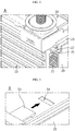
FIG. 3 is an enlarged perspective view showing a portion A ofFIG. 2 . -
FIG. 4 is a perspective view showing a state where the slider ofFIG. 3 is inserted a little further. -
FIG. 5 is an enlarged perspective view showing a portion B ofFIG. 2 . -
FIG. 6 is a perspective view showing a state where the stopper ofFIG. 5 is hooked to the fixing portion. -
FIG. 2 is a perspective view showing an air-cooling battery pack according to an embodiment of the present disclosure. - Referring to
FIG. 2 , a battery pack according to an embodiment of the present disclosure includes acell assembly 10 having a plurality of cells,air ducts 20 disposed to contact both side edges of thecell assembly 10, and aBMS plate 30 detachably assembled to couplinggrooves 22 formed at the top of theair ducts 20. - Each cell of the
cell assembly 10 has a thin plate-like body and preferably has a pouch cell structure. The pouch cell includes a positive electrode, a separator and a negative electrode, which are alternately stacked so that an electrode tab is drawn out from at least one side thereof. The positive electrode and the negative electrode are fabricated by coating slurry containing an electrode active material, a binder resin, a conductive agent and other additives to at least one side of a current collector. In the case of a positive electrode, a common positive electrode active material such as a lithium-containing transition metal oxide may be used as the electrode active material. In the case of a negative electrode, a common negative electrode active material such as a lithium metal capable of intercalating and de-intercalating lithium ions, a carbonaceous material, a metal compound, or compounds thereof may be used as the electrode active material. In addition, the separator may adopt a common porous polymer film used in a lithium secondary battery. - A common electrolyte for a lithium secondary battery may be employed as the electrolyte contained in a pouch case together with the electrode assembly. The pouch case is formed of sheet material and has an accommodating portion for accommodating the electrode assembly. Preferably, the pouch case is formed by coupling a first case and a second case, which are prepared by processing a sheet material into a predetermined shape. The sheet material of the pouch case has a multi-layered structure including an outer resin layer provided at an outermost side and made of an insulating material such as polyethylene terephthalate (PET) or nylon, a metal layer made of an aluminum material to maintain mechanical strength and prevent penetration of moisture and oxygen, and an inner resin layer made of a polyolefin-based material and serving as a sealing material due to thermal adhesiveness.
- In the sheet material of the pouch case, a predetermined adhesive resin layer may be interposed between the inner resin layer and the metal layer and between the outer resin layer and the metal layer, if necessary. The adhesive resin layer is intended for smooth attachment between different kinds of materials and is formed as a single layer or a multilayer. The adhesive material may be commonly made of a polyolefin resin, or a polyurethane resin for smooth processing, or a mixture thereof.
- In the
cell assembly 10, the plurality of cells are disposed at predetermined intervals in the thickness direction to form a substantially stacked structure. - The
air duct 20 is for air-cooling thecell assembly 10 and includes a duct made of an aluminum material and having an air passage for moving a cooling air. An outer surface of theair duct 20 oriented toward thecell assembly 10 is disposed in contact with the edge portion of thecell assembly 10. At this time, it is preferable that a heat transfer material made of a thermal interface material (TIM) having high thermal conductivity is interposed between the edge portion of thecell assembly 10 and theair duct 20. - A
truss structure 21 formed by repeatedly arranging frames to form a substantially triangular shape is provided inside the duct of theair duct 20 to improve the cooling performance and provide sufficient mechanical rigidity for protecting thecell assembly 10 from an external impact or the like. - In addition, a plurality of uneven patterns are formed on the surface of the
truss structure 21 of theair duct 20. The uneven patterns improve the cooling performance by increasing the internal surface area of theair duct 20. - The
air duct 20 is provided on both sides of thecell assembly 10, respectively, and is disposed so that the longitudinal direction thereof is extended identical to the longitudinal direction of thecell assembly 10. - A
coupling groove 22 to which theBMS plate 30 may be assembled is provided at the top of theair duct 20. Preferably, thecoupling groove 22 may be provided by aguide rib 23 formed at the top of theair duct 20. Theguide rib 23 is formed integrally with theair duct 20 to extend in the longitudinal direction at the top surface of theair duct 20, and thecoupling groove 22 is formed at theguide rib 23 such that thecoupling groove 22 has a section of a '⊂' shape and its opening is oriented toward the inside of the battery pack. - The
BMS plate 30 is a circuit board assembly to which a battery management system (BMS) for managing the cells and various electrical components required for the battery pack are mounted. TheBMS plate 30 may be provided as a single plate or a plurality of plates assembled. - The
BMS plate 30 is disposed at an upper portion of the stacked structure of the cell assembly and both side edges of theBMS plate 30 are assembled by being slidably inserted into thecoupling groove 22 of theair duct 20. For this, as shown inFIG. 3 , a bar-type slider 31 shaped and sized to be inserted into thecoupling groove 22 is formed at both side edges of theBMS plate 30 to extend in the longitudinal direction of theBMS plate 30. - The
slider 31 is preferably integrally formed at theBMS plate 30 by plastic injection molding. Agradient structure 32 inclined to have a gradually increasing thickness in a direction opposite to the inserting direction is formed in a portion of theslider 31. Thegradient structure 32 is for pressing theslider 31 into thecoupling groove 22 and prevents theBMS plate 30 from being separated from theair duct 20 due to external vibration or impact or being damaged by shaking. - Since the
guide rib 23 forming thecoupling groove 22 is made of aluminum material integrally with theair duct 20, it is preferable that theslider 31 is made of plastic material and tightly inserted into thecoupling groove 22. It is preferable that thegradient structure 32 is located close to a rear portion of theslider 31 so that theslider 31 is tightly fitted into thecoupling groove 22 and simultaneously theBMS plate 30 is completely inserted. - In order to fix the position of the
BMS plate 30 assembled in a sliding manner more firmly, astopper 33 having a hook structure and made of plastic material is provided on a part of theBMS plate 30. Thestopper 33 may be integrally formed when theBMS plate 30 is formed. In addition, a fixingplate 34 having a hole or groove form corresponding to thestopper 33 is provided at theair duct 20 or a predetermined support plate located under theBMS plate 30. When theslider 31 is completely inserted, thestopper 33 is hooked to the fixingportion 34 to effectively prevent movement of theBMS plate 30. - The battery pack configured as above according to an embodiment of the present disclosure is assembled by disposing the
air ducts 20 at both side edges of thecell assembly 10 and then slidably coupling theBMS plate 30 to theair duct 20 at a location above thecell assembly 10. - The
truss structure 21 is provided inside theair duct 20 to secure sufficient rigidity and increase the heat transfer area. In addition, due to the plurality of uneven patterns formed at thetruss structure 21, the heat transfer area is further increased to improve the cooling performance. - The cooling air introduced into one opening of the
air duct 20 moves along the air passage inside theair duct 20 and is forcibly discharged out at the opposite opening, during which, thecell assembly 1 is air-cooled. - In the assembling process of the
BMS plate 30, a front end of theslider 31 provided at the edge of theBMS plate 30 is pushed and inserted into thecoupling groove 22 of theguide rib 23 integrated at the top of theair duct 20 so that theplate 30 is disposed at the upper portion of thecell assembly 10. - Immediately before the
BMS plate 30 is completely inserted into theair duct 20, theBMS plate 30 is gradually inserted more tightly due to thegradient structure 32 of theslider 31, and finally thestopper 33 is hooked to the fixingportion 34 to fix the assembled state. - By means of the structure in which both side edges of the
BMS plate 30 are coupled in contact with theair duct 20, the heat generated from theBMS plate 30 may be efficiently conducted to theair duct 20 and cooled. - The battery pack according to the present disclosure may simplify the assembling process and reduce the material cost since the bolting process may be omitted when the
BMS plate 30 is coupled, compared to the conventional battery pack. - In addition, since the battery pack is cooled by the
air ducts 20 disposed at both sides of the cell assembly, the space utilization in the cell thickness direction may be enhanced. Also, by means of thetruss structure 21 provided inside theair duct 20, it is possible to sufficiently secure the mechanical stiffness and improve the cooling performance. - The present disclosure has been described in detail. However, it should be understood that the detailed description and specific examples, while indicating preferred embodiments of the disclosure, are given by way of illustration only, since various changes and modifications within the scope of the disclosure will become apparent to those skilled in the art from this detailed description.
- If the present disclosure is applied, the assembling work for inserting the BMS plate into the battery pack is improved, thereby reducing a process number and material costs, compared to the conventional bolting assembling work.
Claims (8)
- An air-cooling battery pack, comprising:a cell assembly having a plurality of cells stacked therein;an air duct disposed to contact the cell assembly and having an air passage formed therein to allow a cooling air to move therethrough;a coupling groove formed at the air duct to elongate in a longitudinal direction; anda battery management system (BMS) plate having a BMS for managing the cells and assembled to the air duct by a slider slidably inserted into the coupling groove.
- The air-cooling battery pack according to claim 1,
wherein the air duct is respectively disposed at both side edges of the cell assembly. - The air-cooling battery pack according to claim 2,
wherein the slider is respectively provided at both side edges of the BMS plate, and
wherein the coupling groove is provided at the top of the air duct. - The air-cooling battery pack according to claim 3,
wherein a guide rib elongating in a longitudinal direction is formed at a top surface of the air duct to be integrated with the air duct, and
wherein the coupling groove has a section with a '⊂' shape and is formed at the guide rib so that an opening thereof is oriented toward the inside of the battery pack. - The air-cooling battery pack according to claim 4,
wherein the slider has a gradient structure with a gradually increasing thickness in a direction opposite to an inserting direction thereof. - The air-cooling battery pack according to claim 5,
wherein the air duct is made of aluminum material, and
wherein the slider is made of plastic material and is inserted into the coupling groove. - The air-cooling battery pack according to claim 6, further comprising:a fixing portion having a hole or groove form; anda stopper having a hook form and provided at a part of the BMS plate with plastic material, the stopper being coupled to the fixing portion in a state where the slider is completely inserted.
- The air-cooling battery pack according to claim 2,
wherein a truss structure is provided inside the air duct.
Priority Applications (1)
| Application Number | Priority Date | Filing Date | Title |
|---|---|---|---|
| PL17880468T PL3454409T3 (en) | 2016-12-14 | 2017-12-06 | Air-cooled battery pack having improved assembly structure |
Applications Claiming Priority (2)
| Application Number | Priority Date | Filing Date | Title |
|---|---|---|---|
| KR1020160170653A KR102172516B1 (en) | 2016-12-14 | 2016-12-14 | Air cooling type secondary battery pack |
| PCT/KR2017/014254 WO2018110896A1 (en) | 2016-12-14 | 2017-12-06 | Air-cooled battery pack having improved assembly structure |
Publications (3)
| Publication Number | Publication Date |
|---|---|
| EP3454409A1 true EP3454409A1 (en) | 2019-03-13 |
| EP3454409A4 EP3454409A4 (en) | 2019-05-01 |
| EP3454409B1 EP3454409B1 (en) | 2021-02-03 |
Family
ID=62558895
Family Applications (1)
| Application Number | Title | Priority Date | Filing Date |
|---|---|---|---|
| EP17880468.8A Active EP3454409B1 (en) | 2016-12-14 | 2017-12-06 | Air-cooled battery pack having improved assembly structure |
Country Status (7)
| Country | Link |
|---|---|
| US (1) | US11177517B2 (en) |
| EP (1) | EP3454409B1 (en) |
| JP (1) | JP6719595B2 (en) |
| KR (1) | KR102172516B1 (en) |
| CN (1) | CN109314288B (en) |
| PL (1) | PL3454409T3 (en) |
| WO (1) | WO2018110896A1 (en) |
Cited By (1)
| Publication number | Priority date | Publication date | Assignee | Title |
|---|---|---|---|---|
| CN111653702A (en) * | 2020-06-11 | 2020-09-11 | 鹏盛国能(深圳)新能源集团有限公司 | An all-oxide solid-state silicon carbon lithium tantalum battery structure |
Families Citing this family (5)
| Publication number | Priority date | Publication date | Assignee | Title |
|---|---|---|---|---|
| CN110571486A (en) * | 2019-09-27 | 2019-12-13 | 深圳市驰普科达科技有限公司 | battery box |
| KR102349108B1 (en) * | 2019-12-05 | 2022-01-12 | 주식회사 호원 | Battery assembly |
| KR102812829B1 (en) | 2020-03-05 | 2025-05-23 | 주식회사 엘지에너지솔루션 | Battery pack with structure of improved convenience for carrying and assembling and improved safety |
| CN113471568B (en) * | 2021-07-08 | 2022-09-20 | 奇瑞商用车(安徽)有限公司 | A heat dissipation structure of a lithium battery pack and a heat dissipation method thereof |
| CN116565376B (en) * | 2023-05-04 | 2024-02-20 | 江苏果下科技有限公司 | A battery box cooling device that diverts hot air |
Family Cites Families (22)
| Publication number | Priority date | Publication date | Assignee | Title |
|---|---|---|---|---|
| EP1969655B1 (en) * | 2005-12-27 | 2011-11-23 | LG Chem, Ltd. | Frame member and battery pack employed with the same |
| JP5518386B2 (en) * | 2009-07-17 | 2014-06-11 | 三洋電機株式会社 | Battery system |
| JP5496576B2 (en) | 2009-08-26 | 2014-05-21 | 三洋電機株式会社 | Battery pack |
| KR20110024954A (en) * | 2009-09-03 | 2011-03-09 | 삼성전자주식회사 | Secondary Battery Module with Cooling Channel |
| JP5417162B2 (en) * | 2009-12-28 | 2014-02-12 | 株式会社日立製作所 | Power storage device |
| KR101256296B1 (en) * | 2010-12-30 | 2013-04-18 | 주식회사 포스코아이씨티 | Battery system |
| KR101355961B1 (en) | 2011-04-25 | 2014-02-03 | 주식회사 엘지화학 | Apparatus for containing battery pack and apparatus for cooling power storage battery pack using it |
| WO2013048060A2 (en) | 2011-09-29 | 2013-04-04 | 주식회사 엘지화학 | Battery pack having a novel cooling structure |
| KR101866345B1 (en) * | 2011-12-02 | 2018-06-12 | 에스케이이노베이션 주식회사 | Battery Module |
| JP6234929B2 (en) * | 2012-08-30 | 2017-11-22 | 三洋電機株式会社 | Power supply device, vehicle equipped with power supply device, power storage device, and method of manufacturing power supply device |
| KR20140075465A (en) * | 2012-12-11 | 2014-06-19 | 삼성전자주식회사 | Fuel cell stack having cooling plate for improving temperature distribution |
| KR101650027B1 (en) | 2013-09-27 | 2016-08-22 | 주식회사 엘지화학 | Secondary Battery Pack Having PCM |
| KR20150044800A (en) | 2013-10-17 | 2015-04-27 | 주식회사 엘지화학 | Battery pack |
| KR101707976B1 (en) | 2013-10-29 | 2017-02-17 | 주식회사 엘지화학 | Battery module equipped with sensing modules having an improved coupling structure |
| CN203631621U (en) | 2013-12-05 | 2014-06-04 | 宁德时代新能源科技有限公司 | Battery module |
| KR101773105B1 (en) * | 2014-07-31 | 2017-08-30 | 주식회사 엘지화학 | Battery module |
| KR102171350B1 (en) | 2014-09-03 | 2020-10-29 | 에스케이이노베이션 주식회사 | Battery tray provided in energy storage system |
| US20160093861A1 (en) * | 2014-09-29 | 2016-03-31 | Apple Inc. | Battery busbar for connection and disconnection |
| CN105633501B (en) | 2014-11-04 | 2017-11-28 | 北京理工大学 | Electric vehicle dynamic cell group liquid stream heat management device, management system and its control method |
| KR20160139807A (en) | 2015-05-28 | 2016-12-07 | 삼성에스디아이 주식회사 | Battery pack |
| CN205621775U (en) * | 2016-01-30 | 2016-10-05 | 华南理工大学 | Multiple exit batteries of electric vehicle air cooling battery box of fin is equipped with |
| CN205609703U (en) * | 2016-02-18 | 2016-09-28 | 宁德时代新能源科技股份有限公司 | Battery module |
-
2016
- 2016-12-14 KR KR1020160170653A patent/KR102172516B1/en active Active
-
2017
- 2017-12-06 PL PL17880468T patent/PL3454409T3/en unknown
- 2017-12-06 US US16/303,252 patent/US11177517B2/en active Active
- 2017-12-06 WO PCT/KR2017/014254 patent/WO2018110896A1/en not_active Ceased
- 2017-12-06 JP JP2018561971A patent/JP6719595B2/en active Active
- 2017-12-06 EP EP17880468.8A patent/EP3454409B1/en active Active
- 2017-12-06 CN CN201780036926.8A patent/CN109314288B/en active Active
Cited By (1)
| Publication number | Priority date | Publication date | Assignee | Title |
|---|---|---|---|---|
| CN111653702A (en) * | 2020-06-11 | 2020-09-11 | 鹏盛国能(深圳)新能源集团有限公司 | An all-oxide solid-state silicon carbon lithium tantalum battery structure |
Also Published As
| Publication number | Publication date |
|---|---|
| KR20180068705A (en) | 2018-06-22 |
| CN109314288A (en) | 2019-02-05 |
| JP2019517114A (en) | 2019-06-20 |
| WO2018110896A1 (en) | 2018-06-21 |
| JP6719595B2 (en) | 2020-07-08 |
| EP3454409A4 (en) | 2019-05-01 |
| US11177517B2 (en) | 2021-11-16 |
| KR102172516B1 (en) | 2020-10-30 |
| US20190207277A1 (en) | 2019-07-04 |
| EP3454409B1 (en) | 2021-02-03 |
| PL3454409T3 (en) | 2021-07-05 |
| CN109314288B (en) | 2021-12-17 |
Similar Documents
| Publication | Publication Date | Title |
|---|---|---|
| US11177517B2 (en) | Air-cooling battery pack having improved assembling structure | |
| US11133551B2 (en) | Battery pack | |
| EP3392957B1 (en) | Air-cooling battery module | |
| EP3062361B1 (en) | Frame for secondary battery and battery module comprising same | |
| EP3467903B1 (en) | Battery pack | |
| EP2432045B1 (en) | Battery cartridge having elastic pressing member, and battery module cotaining the same | |
| US9799862B2 (en) | Battery pack | |
| EP3382790B1 (en) | Battery module having cooling channel, and assembling method and frame assembly thereof | |
| US10658631B2 (en) | Secondary battery | |
| KR102076168B1 (en) | Battery module assembly | |
| KR20220126349A (en) | Manufacturing method of pocketing anode body and pocketing anode body | |
| US20250239739A1 (en) | Battery pack | |
| EP4664606A1 (en) | Battery pack and device including same | |
| KR20230051884A (en) | Battery module and battery pack including the same |
Legal Events
| Date | Code | Title | Description |
|---|---|---|---|
| STAA | Information on the status of an ep patent application or granted ep patent |
Free format text: STATUS: THE INTERNATIONAL PUBLICATION HAS BEEN MADE |
|
| PUAI | Public reference made under article 153(3) epc to a published international application that has entered the european phase |
Free format text: ORIGINAL CODE: 0009012 |
|
| STAA | Information on the status of an ep patent application or granted ep patent |
Free format text: STATUS: REQUEST FOR EXAMINATION WAS MADE |
|
| 17P | Request for examination filed |
Effective date: 20181204 |
|
| AK | Designated contracting states |
Kind code of ref document: A1 Designated state(s): AL AT BE BG CH CY CZ DE DK EE ES FI FR GB GR HR HU IE IS IT LI LT LU LV MC MK MT NL NO PL PT RO RS SE SI SK SM TR |
|
| AX | Request for extension of the european patent |
Extension state: BA ME |
|
| A4 | Supplementary search report drawn up and despatched |
Effective date: 20190403 |
|
| RIC1 | Information provided on ipc code assigned before grant |
Ipc: H01M 2/10 20060101ALI20190328BHEP Ipc: H01M 10/42 20060101ALI20190328BHEP Ipc: H01M 10/6562 20140101ALI20190328BHEP Ipc: H01M 10/6565 20140101ALI20190328BHEP Ipc: H01M 10/647 20140101ALI20190328BHEP Ipc: H01M 10/6556 20140101AFI20190328BHEP Ipc: H01M 10/6561 20140101ALI20190328BHEP Ipc: H01M 10/613 20140101ALI20190328BHEP |
|
| STAA | Information on the status of an ep patent application or granted ep patent |
Free format text: STATUS: EXAMINATION IS IN PROGRESS |
|
| DAV | Request for validation of the european patent (deleted) | ||
| DAX | Request for extension of the european patent (deleted) | ||
| 17Q | First examination report despatched |
Effective date: 20200326 |
|
| GRAP | Despatch of communication of intention to grant a patent |
Free format text: ORIGINAL CODE: EPIDOSNIGR1 |
|
| STAA | Information on the status of an ep patent application or granted ep patent |
Free format text: STATUS: GRANT OF PATENT IS INTENDED |
|
| INTG | Intention to grant announced |
Effective date: 20201013 |
|
| GRAS | Grant fee paid |
Free format text: ORIGINAL CODE: EPIDOSNIGR3 |
|
| GRAA | (expected) grant |
Free format text: ORIGINAL CODE: 0009210 |
|
| STAA | Information on the status of an ep patent application or granted ep patent |
Free format text: STATUS: THE PATENT HAS BEEN GRANTED |
|
| AK | Designated contracting states |
Kind code of ref document: B1 Designated state(s): AL AT BE BG CH CY CZ DE DK EE ES FI FR GB GR HR HU IE IS IT LI LT LU LV MC MK MT NL NO PL PT RO RS SE SI SK SM TR |
|
| REG | Reference to a national code |
Ref country code: GB Ref legal event code: FG4D |
|
| REG | Reference to a national code |
Ref country code: AT Ref legal event code: REF Ref document number: 1359899 Country of ref document: AT Kind code of ref document: T Effective date: 20210215 Ref country code: CH Ref legal event code: EP |
|
| REG | Reference to a national code |
Ref country code: DE Ref legal event code: R096 Ref document number: 602017032435 Country of ref document: DE |
|
| REG | Reference to a national code |
Ref country code: IE Ref legal event code: FG4D |
|
| REG | Reference to a national code |
Ref country code: SE Ref legal event code: TRGR |
|
| REG | Reference to a national code |
Ref country code: NL Ref legal event code: MP Effective date: 20210203 |
|
| REG | Reference to a national code |
Ref country code: LT Ref legal event code: MG9D |
|
| REG | Reference to a national code |
Ref country code: AT Ref legal event code: MK05 Ref document number: 1359899 Country of ref document: AT Kind code of ref document: T Effective date: 20210203 |
|
| PG25 | Lapsed in a contracting state [announced via postgrant information from national office to epo] |
Ref country code: LT Free format text: LAPSE BECAUSE OF FAILURE TO SUBMIT A TRANSLATION OF THE DESCRIPTION OR TO PAY THE FEE WITHIN THE PRESCRIBED TIME-LIMIT Effective date: 20210203 Ref country code: BG Free format text: LAPSE BECAUSE OF FAILURE TO SUBMIT A TRANSLATION OF THE DESCRIPTION OR TO PAY THE FEE WITHIN THE PRESCRIBED TIME-LIMIT Effective date: 20210503 Ref country code: NO Free format text: LAPSE BECAUSE OF FAILURE TO SUBMIT A TRANSLATION OF THE DESCRIPTION OR TO PAY THE FEE WITHIN THE PRESCRIBED TIME-LIMIT Effective date: 20210503 Ref country code: PT Free format text: LAPSE BECAUSE OF FAILURE TO SUBMIT A TRANSLATION OF THE DESCRIPTION OR TO PAY THE FEE WITHIN THE PRESCRIBED TIME-LIMIT Effective date: 20210604 Ref country code: FI Free format text: LAPSE BECAUSE OF FAILURE TO SUBMIT A TRANSLATION OF THE DESCRIPTION OR TO PAY THE FEE WITHIN THE PRESCRIBED TIME-LIMIT Effective date: 20210203 Ref country code: HR Free format text: LAPSE BECAUSE OF FAILURE TO SUBMIT A TRANSLATION OF THE DESCRIPTION OR TO PAY THE FEE WITHIN THE PRESCRIBED TIME-LIMIT Effective date: 20210203 Ref country code: GR Free format text: LAPSE BECAUSE OF FAILURE TO SUBMIT A TRANSLATION OF THE DESCRIPTION OR TO PAY THE FEE WITHIN THE PRESCRIBED TIME-LIMIT Effective date: 20210504 |
|
| PG25 | Lapsed in a contracting state [announced via postgrant information from national office to epo] |
Ref country code: AT Free format text: LAPSE BECAUSE OF FAILURE TO SUBMIT A TRANSLATION OF THE DESCRIPTION OR TO PAY THE FEE WITHIN THE PRESCRIBED TIME-LIMIT Effective date: 20210203 Ref country code: NL Free format text: LAPSE BECAUSE OF FAILURE TO SUBMIT A TRANSLATION OF THE DESCRIPTION OR TO PAY THE FEE WITHIN THE PRESCRIBED TIME-LIMIT Effective date: 20210203 Ref country code: LV Free format text: LAPSE BECAUSE OF FAILURE TO SUBMIT A TRANSLATION OF THE DESCRIPTION OR TO PAY THE FEE WITHIN THE PRESCRIBED TIME-LIMIT Effective date: 20210203 Ref country code: RS Free format text: LAPSE BECAUSE OF FAILURE TO SUBMIT A TRANSLATION OF THE DESCRIPTION OR TO PAY THE FEE WITHIN THE PRESCRIBED TIME-LIMIT Effective date: 20210203 |
|
| PG25 | Lapsed in a contracting state [announced via postgrant information from national office to epo] |
Ref country code: IS Free format text: LAPSE BECAUSE OF FAILURE TO SUBMIT A TRANSLATION OF THE DESCRIPTION OR TO PAY THE FEE WITHIN THE PRESCRIBED TIME-LIMIT Effective date: 20210603 |
|
| PG25 | Lapsed in a contracting state [announced via postgrant information from national office to epo] |
Ref country code: SM Free format text: LAPSE BECAUSE OF FAILURE TO SUBMIT A TRANSLATION OF THE DESCRIPTION OR TO PAY THE FEE WITHIN THE PRESCRIBED TIME-LIMIT Effective date: 20210203 Ref country code: CZ Free format text: LAPSE BECAUSE OF FAILURE TO SUBMIT A TRANSLATION OF THE DESCRIPTION OR TO PAY THE FEE WITHIN THE PRESCRIBED TIME-LIMIT Effective date: 20210203 Ref country code: EE Free format text: LAPSE BECAUSE OF FAILURE TO SUBMIT A TRANSLATION OF THE DESCRIPTION OR TO PAY THE FEE WITHIN THE PRESCRIBED TIME-LIMIT Effective date: 20210203 |
|
| REG | Reference to a national code |
Ref country code: DE Ref legal event code: R097 Ref document number: 602017032435 Country of ref document: DE |
|
| PG25 | Lapsed in a contracting state [announced via postgrant information from national office to epo] |
Ref country code: RO Free format text: LAPSE BECAUSE OF FAILURE TO SUBMIT A TRANSLATION OF THE DESCRIPTION OR TO PAY THE FEE WITHIN THE PRESCRIBED TIME-LIMIT Effective date: 20210203 Ref country code: DK Free format text: LAPSE BECAUSE OF FAILURE TO SUBMIT A TRANSLATION OF THE DESCRIPTION OR TO PAY THE FEE WITHIN THE PRESCRIBED TIME-LIMIT Effective date: 20210203 Ref country code: SK Free format text: LAPSE BECAUSE OF FAILURE TO SUBMIT A TRANSLATION OF THE DESCRIPTION OR TO PAY THE FEE WITHIN THE PRESCRIBED TIME-LIMIT Effective date: 20210203 |
|
| PLBE | No opposition filed within time limit |
Free format text: ORIGINAL CODE: 0009261 |
|
| STAA | Information on the status of an ep patent application or granted ep patent |
Free format text: STATUS: NO OPPOSITION FILED WITHIN TIME LIMIT |
|
| 26N | No opposition filed |
Effective date: 20211104 |
|
| PG25 | Lapsed in a contracting state [announced via postgrant information from national office to epo] |
Ref country code: AL Free format text: LAPSE BECAUSE OF FAILURE TO SUBMIT A TRANSLATION OF THE DESCRIPTION OR TO PAY THE FEE WITHIN THE PRESCRIBED TIME-LIMIT Effective date: 20210203 Ref country code: ES Free format text: LAPSE BECAUSE OF FAILURE TO SUBMIT A TRANSLATION OF THE DESCRIPTION OR TO PAY THE FEE WITHIN THE PRESCRIBED TIME-LIMIT Effective date: 20210203 |
|
| PG25 | Lapsed in a contracting state [announced via postgrant information from national office to epo] |
Ref country code: SI Free format text: LAPSE BECAUSE OF FAILURE TO SUBMIT A TRANSLATION OF THE DESCRIPTION OR TO PAY THE FEE WITHIN THE PRESCRIBED TIME-LIMIT Effective date: 20210203 |
|
| PG25 | Lapsed in a contracting state [announced via postgrant information from national office to epo] |
Ref country code: IT Free format text: LAPSE BECAUSE OF FAILURE TO SUBMIT A TRANSLATION OF THE DESCRIPTION OR TO PAY THE FEE WITHIN THE PRESCRIBED TIME-LIMIT Effective date: 20210203 |
|
| PG25 | Lapsed in a contracting state [announced via postgrant information from national office to epo] |
Ref country code: IS Free format text: LAPSE BECAUSE OF FAILURE TO SUBMIT A TRANSLATION OF THE DESCRIPTION OR TO PAY THE FEE WITHIN THE PRESCRIBED TIME-LIMIT Effective date: 20210603 |
|
| PG25 | Lapsed in a contracting state [announced via postgrant information from national office to epo] |
Ref country code: MC Free format text: LAPSE BECAUSE OF FAILURE TO SUBMIT A TRANSLATION OF THE DESCRIPTION OR TO PAY THE FEE WITHIN THE PRESCRIBED TIME-LIMIT Effective date: 20210203 |
|
| REG | Reference to a national code |
Ref country code: CH Ref legal event code: PL |
|
| REG | Reference to a national code |
Ref country code: BE Ref legal event code: MM Effective date: 20211231 |
|
| PG25 | Lapsed in a contracting state [announced via postgrant information from national office to epo] |
Ref country code: LU Free format text: LAPSE BECAUSE OF NON-PAYMENT OF DUE FEES Effective date: 20211206 Ref country code: IE Free format text: LAPSE BECAUSE OF NON-PAYMENT OF DUE FEES Effective date: 20211206 |
|
| PG25 | Lapsed in a contracting state [announced via postgrant information from national office to epo] |
Ref country code: BE Free format text: LAPSE BECAUSE OF NON-PAYMENT OF DUE FEES Effective date: 20211231 |
|
| PG25 | Lapsed in a contracting state [announced via postgrant information from national office to epo] |
Ref country code: LI Free format text: LAPSE BECAUSE OF NON-PAYMENT OF DUE FEES Effective date: 20211231 Ref country code: CH Free format text: LAPSE BECAUSE OF NON-PAYMENT OF DUE FEES Effective date: 20211231 |
|
| REG | Reference to a national code |
Ref country code: DE Ref legal event code: R081 Ref document number: 602017032435 Country of ref document: DE Owner name: LG ENERGY SOLUTION, LTD., KR Free format text: FORMER OWNER: LG CHEM, LTD., SEOUL, KR |
|
| P01 | Opt-out of the competence of the unified patent court (upc) registered |
Effective date: 20230512 |
|
| PG25 | Lapsed in a contracting state [announced via postgrant information from national office to epo] |
Ref country code: CY Free format text: LAPSE BECAUSE OF FAILURE TO SUBMIT A TRANSLATION OF THE DESCRIPTION OR TO PAY THE FEE WITHIN THE PRESCRIBED TIME-LIMIT Effective date: 20210203 |
|
| PG25 | Lapsed in a contracting state [announced via postgrant information from national office to epo] |
Ref country code: HU Free format text: LAPSE BECAUSE OF FAILURE TO SUBMIT A TRANSLATION OF THE DESCRIPTION OR TO PAY THE FEE WITHIN THE PRESCRIBED TIME-LIMIT; INVALID AB INITIO Effective date: 20171206 |
|
| REG | Reference to a national code |
Ref country code: GB Ref legal event code: 732E Free format text: REGISTERED BETWEEN 20230901 AND 20230906 |
|
| PG25 | Lapsed in a contracting state [announced via postgrant information from national office to epo] |
Ref country code: MK Free format text: LAPSE BECAUSE OF FAILURE TO SUBMIT A TRANSLATION OF THE DESCRIPTION OR TO PAY THE FEE WITHIN THE PRESCRIBED TIME-LIMIT Effective date: 20210203 |
|
| PG25 | Lapsed in a contracting state [announced via postgrant information from national office to epo] |
Ref country code: TR Free format text: LAPSE BECAUSE OF FAILURE TO SUBMIT A TRANSLATION OF THE DESCRIPTION OR TO PAY THE FEE WITHIN THE PRESCRIBED TIME-LIMIT Effective date: 20210203 |
|
| PG25 | Lapsed in a contracting state [announced via postgrant information from national office to epo] |
Ref country code: MT Free format text: LAPSE BECAUSE OF FAILURE TO SUBMIT A TRANSLATION OF THE DESCRIPTION OR TO PAY THE FEE WITHIN THE PRESCRIBED TIME-LIMIT Effective date: 20210203 |
|
| PGFP | Annual fee paid to national office [announced via postgrant information from national office to epo] |
Ref country code: DE Payment date: 20251120 Year of fee payment: 9 |
|
| PGFP | Annual fee paid to national office [announced via postgrant information from national office to epo] |
Ref country code: GB Payment date: 20251120 Year of fee payment: 9 |
|
| PGFP | Annual fee paid to national office [announced via postgrant information from national office to epo] |
Ref country code: FR Payment date: 20251125 Year of fee payment: 9 |
|
| PGFP | Annual fee paid to national office [announced via postgrant information from national office to epo] |
Ref country code: SE Payment date: 20251121 Year of fee payment: 9 |
|
| PGFP | Annual fee paid to national office [announced via postgrant information from national office to epo] |
Ref country code: PL Payment date: 20251124 Year of fee payment: 9 |