EP3454300A1 - Three dimensional reconstruction method, apparatus and non-transitory computer readable storage medium thereof - Google Patents
Three dimensional reconstruction method, apparatus and non-transitory computer readable storage medium thereof Download PDFInfo
- Publication number
- EP3454300A1 EP3454300A1 EP18193938.0A EP18193938A EP3454300A1 EP 3454300 A1 EP3454300 A1 EP 3454300A1 EP 18193938 A EP18193938 A EP 18193938A EP 3454300 A1 EP3454300 A1 EP 3454300A1
- Authority
- EP
- European Patent Office
- Prior art keywords
- hmd
- camera
- rotation amount
- displacement vector
- image
- Prior art date
- Legal status (The legal status is an assumption and is not a legal conclusion. Google has not performed a legal analysis and makes no representation as to the accuracy of the status listed.)
- Granted
Links
Images


Classifications
-
- G—PHYSICS
- G06—COMPUTING OR CALCULATING; COUNTING
- G06T—IMAGE DATA PROCESSING OR GENERATION, IN GENERAL
- G06T7/00—Image analysis
- G06T7/80—Analysis of captured images to determine intrinsic or extrinsic camera parameters, i.e. camera calibration
-
- H—ELECTRICITY
- H04—ELECTRIC COMMUNICATION TECHNIQUE
- H04N—PICTORIAL COMMUNICATION, e.g. TELEVISION
- H04N13/00—Stereoscopic video systems; Multi-view video systems; Details thereof
- H04N13/10—Processing, recording or transmission of stereoscopic or multi-view image signals
- H04N13/106—Processing image signals
- H04N13/122—Improving the three-dimensional [3D] impression of stereoscopic images by modifying image signal contents, e.g. by filtering or adding monoscopic depth cues
-
- G—PHYSICS
- G06—COMPUTING OR CALCULATING; COUNTING
- G06T—IMAGE DATA PROCESSING OR GENERATION, IN GENERAL
- G06T7/00—Image analysis
- G06T7/20—Analysis of motion
- G06T7/292—Multi-camera tracking
-
- G—PHYSICS
- G06—COMPUTING OR CALCULATING; COUNTING
- G06T—IMAGE DATA PROCESSING OR GENERATION, IN GENERAL
- G06T7/00—Image analysis
- G06T7/50—Depth or shape recovery
- G06T7/55—Depth or shape recovery from multiple images
-
- G—PHYSICS
- G06—COMPUTING OR CALCULATING; COUNTING
- G06T—IMAGE DATA PROCESSING OR GENERATION, IN GENERAL
- G06T7/00—Image analysis
- G06T7/70—Determining position or orientation of objects or cameras
- G06T7/73—Determining position or orientation of objects or cameras using feature-based methods
- G06T7/74—Determining position or orientation of objects or cameras using feature-based methods involving reference images or patches
-
- H—ELECTRICITY
- H04—ELECTRIC COMMUNICATION TECHNIQUE
- H04N—PICTORIAL COMMUNICATION, e.g. TELEVISION
- H04N13/00—Stereoscopic video systems; Multi-view video systems; Details thereof
- H04N13/20—Image signal generators
- H04N13/204—Image signal generators using stereoscopic image cameras
- H04N13/239—Image signal generators using stereoscopic image cameras using two two-dimensional [2D] image sensors having a relative position equal to or related to the interocular distance
-
- H—ELECTRICITY
- H04—ELECTRIC COMMUNICATION TECHNIQUE
- H04N—PICTORIAL COMMUNICATION, e.g. TELEVISION
- H04N13/00—Stereoscopic video systems; Multi-view video systems; Details thereof
- H04N13/30—Image reproducers
- H04N13/332—Displays for viewing with the aid of special glasses or head-mounted displays [HMD]
- H04N13/344—Displays for viewing with the aid of special glasses or head-mounted displays [HMD] with head-mounted left-right displays
-
- G—PHYSICS
- G06—COMPUTING OR CALCULATING; COUNTING
- G06T—IMAGE DATA PROCESSING OR GENERATION, IN GENERAL
- G06T2207/00—Indexing scheme for image analysis or image enhancement
- G06T2207/10—Image acquisition modality
- G06T2207/10028—Range image; Depth image; 3D point clouds
-
- G—PHYSICS
- G06—COMPUTING OR CALCULATING; COUNTING
- G06T—IMAGE DATA PROCESSING OR GENERATION, IN GENERAL
- G06T2207/00—Indexing scheme for image analysis or image enhancement
- G06T2207/30—Subject of image; Context of image processing
- G06T2207/30244—Camera pose
-
- H—ELECTRICITY
- H04—ELECTRIC COMMUNICATION TECHNIQUE
- H04N—PICTORIAL COMMUNICATION, e.g. TELEVISION
- H04N13/00—Stereoscopic video systems; Multi-view video systems; Details thereof
- H04N2013/0074—Stereoscopic image analysis
- H04N2013/0081—Depth or disparity estimation from stereoscopic image signals
Definitions
- the present disclosure relates to three dimensional (3D) technology. More particularly, the present disclosure relates to a 3D reconstruction method, a 3D reconstruction apparatus and a non-transitory computer readable storage medium thereof.
- a user In order to experience the virtual reality environment, a user needs to view the displayed images through the display apparatus disposed at such as, but not limited a head-mounted device (HMD) wear by the user.
- the displayed images may be generated from the cameras disposed at the HMD.
- the 3D reconstruction can not be performed accurately. Under such a condition, the user is not able to experience the accurate 3D environment.
- An aspect of the present disclosure is to provide a three dimensional (3D) reconstruction method used in a 3D reconstruction apparatus that includes the steps outlined below.
- a plurality of positioning signals are received by a signal receiver disposed at a head mounted device (HMD) at a first time spot and a second time spot to determine a HMD displacement vector and a HMD rotation amount according to the positioning signals.
- a first image at the first time spot and a second image at the second time spot are retrieved by a first camera disposed at the HMD to determine a first camera rotation amount according to the first image and the second image.
- a relative rotation amount and a relative displacement vector between the HMD and the first camera are calculated.
- a first camera displacement vector of the first camera is calculated according to the HMD displacement vector, the HMD rotation amount, the relative rotation amount and the relative displacement vector.
- Depth information of the first image and the second image is obtained based on the first camera displacement vector and the first camera rotation amount.
- 3D reconstruction is performed according to images retrieved by the first camera and the depth information.
- Another aspect of the present disclosure is to provide a 3D reconstruction apparatus used in a HMD that includes a storage module, a signal receiver, a first camera and a processing module.
- the storage module is configured to store a plurality of computer-executable instructions.
- the processing module is electrically coupled to the storage module and the signal receiver and is configured to retrieve and execute the computer-executable instructions to perform a reconstruction method when the computer-executable instructions are executed.
- the reconstruction method includes the steps outlined below. A plurality of positioning signals are received by the signal receiver at a first time spot and a second time spot to determine a HMD displacement vector and a HMD rotation amount according to the positioning signals.
- a first image at the first time spot and a second image at the second time spot are retrieved by the first camera to determine a first camera rotation amount according to the first image and the second image.
- a relative rotation amount and a relative displacement vector between the HMD and the first camera are calculated.
- a first camera displacement vector of the first camera is calculated according to the HMD displacement vector, the HMD rotation amount, the relative rotation amount and the relative displacement vector.
- Depth information of the first image and the second image is obtained based on the first camera displacement vector and the first camera rotation amount.
- 3D reconstruction is performed according to images retrieved by the first camera and the depth information.
- Yet another aspect of the present disclosure is to provide a non-transitory computer readable storage medium that stores a computer program comprising a plurality of computer-executable instructions to perform a 3D reconstruction method used in a 3D reconstruction apparatus used in a head-mounted device
- the 3D reconstruction apparatus at least includes a storage module, a signal receiver, a first camera and a processing module electrically coupled to the storage module, the signal receiver and the first camera and configured to retrieve and execute the computer-executable instructions to perform the 3D reconstruction method when the computer-executable instructions are executed.
- the 3D reconstruction method includes the steps outlined below.
- a plurality of positioning signals are received by the signal receiver disposed at a head mounted device (HMD) at a first time spot and a second time spot to determine a HMD displacement vector and a HMD rotation amount according to the positioning signals.
- a first image at the first time spot and a second image at the second time spot are retrieved by the first camera disposed at the HMD to determine a first camera rotation amount according to the first image and the second image.
- a relative rotation amount and a relative displacement vector between the HMD and the first camera are calculated.
- a first camera displacement vector of the first camera is calculated according to the HMD displacement vector, the HMD rotation amount, the relative rotation amount and the relative displacement vector.
- Depth information of the first image and the second image is obtained based on the first camera displacement vector and the first camera rotation amount.
- 3D reconstruction is performed according to images retrieved by the first camera and the depth information.
- FIG. 1 is a block diagram of a 3D reconstruction apparatus 1 in an embodiment of the present invention.
- the 3D reconstruction apparatus 1 is used in a head-mounted device (HMD, not illustrated in FIG. 1 ). More specifically, the components of the 3D reconstruction apparatus 1 are disposed at various positions of the HMD.
- HMD head-mounted device
- the 3D reconstruction apparatus 1 includes a storage module 10, a signal receiver 12, a first camera 14 and a processing module 16.
- the storage unit 10 can be such as, but not limited to CD ROM, RAM, ROM, floppy disk, hard disk or optic magnetic disk.
- the storage unit 10 is configured to store a plurality of computer-executable instructions 100.
- the signal receiver 12 is disposed at the HMD and is configured to receive positioning signals 181 from a plurality of signal positioning apparatus 18.
- the signal positioning apparatus 18 are, for example, lighthouses that deliver the positioning signals 181 in the form of such as, but not limited to electromagnetic signals or supersonic signals. As a result, by keeping receiving the positioning signals 181, the motion of the HMD can be determined.
- the first camera 14 is configured to retrieve images at different time spots.
- the first camera 14 is a camera with either charge coupled device (CCD) or complementary metal oxide semiconductor (CMOS) image sensors.
- CCD charge coupled device
- CMOS complementary metal oxide semiconductor
- the processing module 16 is electrically coupled to the storage unit 10. In an embodiment, the processing module 16 is configured to retrieve and execute the computer-executable instructions 100 to operate the function of the 3D reconstruction apparatus 1 accordingly.
- the processing module 16 is able to perform 3D reconstruction accordingly.
- FIG. 2 The detail of the function of the 3D reconstruction apparatus 1 is described in the following paragraphs in accompany with FIG. 2 , FIG. 3A and FIG. 3B .
- FIG. 2 is a flow chart of a 3D reconstruction method 200 in an embodiment of the present invention.
- the 3D reconstruction method 200 can be used in the 3D reconstruction apparatus 1 illustrated in FIG. 1 .
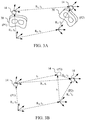
- FIG. 3A is a diagram illustrating the motion of a HMD 30 that the 3D reconstruction apparatus 1 locates and the motion of the first camera 14 in an embodiment of the present invention. As described above, the first camera 14 is disposed at the HMD 30 as well.
- FIG. 3B is a diagram illustrating a decomposed motion of the first camera 14 in FIG. 3A without illustrating the HMD 30 in an embodiment of the present invention.
- the 3D reconstruction method 200 includes the steps outlined below (The steps are not recited in the sequence in which the steps are performed. That is, unless the sequence of the steps is expressly indicated, the sequence of the steps is interchangeable, and all or part of the steps may be simultaneously, partially simultaneously, or sequentially performed).
- step 201 the positioning signals 181 are received from the positioning apparatus 18 by the signal receiver 12 at a first time spot and a second time spot to determine a HMD displacement vector to and a HMD rotation amount R 0 according to the positioning signals 181.
- the signal receiver 12 may include a plurality of receiver units (not illustrated) disposed on various locations on the HMD 30, in which a geometry center of the HMD 30 and a HMD coordinate-system centered at the geometry center can be calculated based on the distribution of the locations of the receiver units.
- the displacement vector and the rotation amount of the HMD coordinate-system can be determined by some well-known algorithms provided with the positioning signals 181 received by the plurality of receiver units. As well known, such algorithms are often formulated in the form to solve the perspective-n-points problem.
- the motion of the HMD 30 can be determined by the signal receiver 12 according to the positioning signals 181, in which the motion can be expressed as the HMD displacement vector to and the HMD rotation amount R 0 .
- the HMD displacement vector t 0 is a 3D vector and the HMD rotation amount R 0 is expressed as a 3D rotation amount, a quaternion or a rotation matrix.
- a first image I1 and a second image I2 are retrieved by the first camera 14 respectively at the first time spot and the second time spot to determine a first camera rotation amount R 1 according to the first image I1 and the second image I2.
- the first camera rotation amount R 1 can be obtained by using known algorithms related to such as, but not limited to epipolar geometry based on the first image I1 and the second image I2, e.g. by calculating the difference of orientations of the objects within the first image I1 and the second image I2.
- a relative rotation amount R 2 and a relative displacement vector t 2 between the HMD 30 and the first camera 14 are calculated by using Euclidean transformation matrix.
- the position and the orientation of the first camera 14 are different from the position and the orientation of the HMD 30 coordinate-system determined according to the distribution of the location of receiver units.
- the relative displacement vector t 2 and the relative rotation amount R 2 exists between the first camera 14 and the HMD 30.
- a motion between a HMD orientation of the HMD 30 at the first time spot (i.e. when the HDM 30 is at the first position P1) to a camera orientation of the first camera 14 at the second time spot (i.e. when the HMD 30 is at the second position P2) is equivalent to a first path and a second path.
- the first path is to rotate the HMD orientation of the HMD 30 at the first time spot (i.e. when the HMD 30 is at the first position P1) for the HMD rotation amount R 0 first and for the relative rotation amount R 2 subsequently.
- the second path is to rotate the HMD orientation at the first time spot for the relative rotation amount R 2 first and for the first camera rotation amount R 1 subsequently.
- the right side of the equal sign in equation 1 means transforming X HMD (a coordinate of a point X in the HMD coordinate system) from the HMD coordinate-system at the first time spot to the camera coordinate-system of the first camera 14 at the first time spot, and then transforming to the camera coordinate-system of the first camera 14 at the second time spot.
- the left side of equation 1 means transforming X HMD from the HMD coordinate-system at the first time spot to the HMD coordinate-system at the second time spot, and then transforming to the camera coordinate-system at the second time spot.
- the relative rotation amount R 2 can be solved by using spectral decomposition method and numerical optimization based on the equation 4.
- the motion of the HMD 30 between the first time spot and the second time spot is decomposed to the HMD displacement corresponding to the HMD displacement vector to and the HMD rotation corresponding to the HMD rotation amount R 0 .
- the motion of the first camera 14 between the first time spot and the second time spot can be decomposed to a first displacement identical to the HMD displacement vector to that displaces to a temporary position P3 and a second displacement corresponding to a displacement vector t 3 , as illustrated in FIG. 3B .
- the displacement vector between the first camera 14 and the HMD 30 under such a condition is t 2 .
- the displacement vector between the first camera 14 and the HMD 30 can be expressed as R 0 -1 t 2 in the HMD coordinate-system at the second time spot before rotation.
- the rotation from "the HMD coordinate-system at the second time spot after rotation” to "the HMD coordinate-system at the second time spot before rotation” is R 0 -1 (i.e. the inverse matrix of R 0 ).
- the displacement vector between the first camera 14 and the HMD 30 is presented as t 2 in "the HMD coordinate-system at the second time spot after rotation” (if the relative position between HMD and camera remains the same during the period in which translation and rotation occurs).
- the displacement vector between the first camera 14 and the HMD 30 from “the camera at the second time spot before rotation” to "the camera at the second time spot after rotation” is represented as R 0 -1 t 2 in "the HMD coordinate-system at the second time spot before rotation”.
- the displacement vector t 3 can be expressed as R 0 -1 t 2 - t 2 in "the HMD coordinate-system at the first time spot".
- the HMD coordinate-system at the first time spot has the same orientation as the HMD coordinate-system at the second time spot without rotation, and so any vector has the same coordinate-representation in these two coordinate-systems at different time spots.
- the first camera displacement vector t 1 described in equations 6 and 8 are substantially under "the HMD coordinate-system at the first time spot".
- the first camera displacement vector t 1 of the first camera 14 is calculated according to the HMD displacement vector t 0 , the HMD rotation amount R 0 , the relative rotation amount R 2 between the first camera 14 and the HMD 30 and the relative displacement vector t 2 between the first camera 14 and the HMD 30.
- step 205 depth information of the first image I1 and the second image 12 is obtained based on the first camera displacement vector t 1 and the first camera rotation amount R 1 .
- the real distance of the objects moving between the first image I1 and the second image I2 can be determined.
- the depth information can thus be obtained.
- step 206 3D reconstruction is performed according to images, e.g. the first image I1 and the second image I2 retrieved by the first camera 14, and the depth information.
- an additional object that has a known size is required to appear in the images taken by the camera for the 3D reconstruction apparatus to obtain the depth information.
- the 3D reconstruction apparatus can not obtain the accurate depth information and is not able to perform 3D reconstruction accurately.
- the 3D reconstruction apparatus 1 and the 3D reconstruction method 200 in the present invention can establish the depth information according to the information from the positioning signals 181 received by the signal receiver 12 and the images retrieved by the first camera 14. Consequently, the 3D reconstruction can be performed accurately based on the accurate depth information.
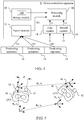
- FIG. 4 is a block diagram of a 3D reconstruction apparatus 4 in an embodiment of the present invention.
- FIG. 5 is a diagram illustrating the motion of a HMD 50 that the 3D reconstruction apparatus 4 locates in an embodiment of the present invention.
- the 3D reconstruction apparatus 4 in FIG. 4 includes components identical to the 3D reconstruction apparatus 1 illustrated in FIG. 1 . As a result, the detail of the identical components is not described herein. However, the 3D reconstruction apparatus 4 further includes a second camera 42.
- both the first camera 14 and the second camera 42 are disposed at the HMD 50.
- the first camera 14 is a left camera and the second camera 42 is a right camera.
- the first camera 14 can be the right camera and the second camera 42 can be the left camera.
- the depth information can be obtained by using either the first camera 14, as illustrated in FIG. 5 , or the second camera 42 based on the method described in FIG. 2 .
- a third image I3 is retrieved by the first camera 14 and a fourth image I4 is retrieved by the second camera 42 at the same time spot.
- a disparity between the third image I3 and the fourth image I4 can be determined accordingly.
- a length of a baseline between the first camera 14 and the second camera 42 i.e. the distance D between the first camera 14 and the second camera 42 in FIG. 5 , can be determined according to the disparity and the depth information.
- the calibration of the baseline of the duo-camera within the 3D reconstruction apparatus 4 can be accomplished.
Landscapes
- Engineering & Computer Science (AREA)
- Computer Vision & Pattern Recognition (AREA)
- Physics & Mathematics (AREA)
- General Physics & Mathematics (AREA)
- Theoretical Computer Science (AREA)
- Multimedia (AREA)
- Signal Processing (AREA)
- Length Measuring Devices By Optical Means (AREA)
- Testing, Inspecting, Measuring Of Stereoscopic Televisions And Televisions (AREA)
Abstract
Description
- This application claims priority to
U.S. Provisional Application Serial Number 62/557,738, filed September 12, 2017 - The present disclosure relates to three dimensional (3D) technology. More particularly, the present disclosure relates to a 3D reconstruction method, a 3D reconstruction apparatus and a non-transitory computer readable storage medium thereof.
- In recent years, virtual reality technology is widely used in the fields such as gaming, engineering and military, etc. In order to experience the virtual reality environment, a user needs to view the displayed images through the display apparatus disposed at such as, but not limited a head-mounted device (HMD) wear by the user. The displayed images may be generated from the cameras disposed at the HMD. However, if the depth information of the images retrieved by the cameras or the baseline between the cameras is unknown, the 3D reconstruction can not be performed accurately. Under such a condition, the user is not able to experience the accurate 3D environment.
- Accordingly, what is needed is a 3D reconstruction method, a 3D reconstruction apparatus and a non-transitory computer readable storage medium thereof to address the above issues.
- An aspect of the present disclosure is to provide a three dimensional (3D) reconstruction method used in a 3D reconstruction apparatus that includes the steps outlined below. A plurality of positioning signals are received by a signal receiver disposed at a head mounted device (HMD) at a first time spot and a second time spot to determine a HMD displacement vector and a HMD rotation amount according to the positioning signals. A first image at the first time spot and a second image at the second time spot are retrieved by a first camera disposed at the HMD to determine a first camera rotation amount according to the first image and the second image. A relative rotation amount and a relative displacement vector between the HMD and the first camera are calculated. A first camera displacement vector of the first camera is calculated according to the HMD displacement vector, the HMD rotation amount, the relative rotation amount and the relative displacement vector. Depth information of the first image and the second image is obtained based on the first camera displacement vector and the first camera rotation amount. 3D reconstruction is performed according to images retrieved by the first camera and the depth information.
- Another aspect of the present disclosure is to provide a 3D reconstruction apparatus used in a HMD that includes a storage module, a signal receiver, a first camera and a processing module. The storage module is configured to store a plurality of computer-executable instructions. The processing module is electrically coupled to the storage module and the signal receiver and is configured to retrieve and execute the computer-executable instructions to perform a reconstruction method when the computer-executable instructions are executed. The reconstruction method includes the steps outlined below. A plurality of positioning signals are received by the signal receiver at a first time spot and a second time spot to determine a HMD displacement vector and a HMD rotation amount according to the positioning signals. A first image at the first time spot and a second image at the second time spot are retrieved by the first camera to determine a first camera rotation amount according to the first image and the second image. A relative rotation amount and a relative displacement vector between the HMD and the first camera are calculated. A first camera displacement vector of the first camera is calculated according to the HMD displacement vector, the HMD rotation amount, the relative rotation amount and the relative displacement vector. Depth information of the first image and the second image is obtained based on the first camera displacement vector and the first camera rotation amount. 3D reconstruction is performed according to images retrieved by the first camera and the depth information.
- Yet another aspect of the present disclosure is to provide a non-transitory computer readable storage medium that stores a computer program comprising a plurality of computer-executable instructions to perform a 3D reconstruction method used in a 3D reconstruction apparatus used in a head-mounted device, the 3D reconstruction apparatus at least includes a storage module, a signal receiver, a first camera and a processing module electrically coupled to the storage module, the signal receiver and the first camera and configured to retrieve and execute the computer-executable instructions to perform the 3D reconstruction method when the computer-executable instructions are executed. The 3D reconstruction method includes the steps outlined below. A plurality of positioning signals are received by the signal receiver disposed at a head mounted device (HMD) at a first time spot and a second time spot to determine a HMD displacement vector and a HMD rotation amount according to the positioning signals. A first image at the first time spot and a second image at the second time spot are retrieved by the first camera disposed at the HMD to determine a first camera rotation amount according to the first image and the second image. A relative rotation amount and a relative displacement vector between the HMD and the first camera are calculated. A first camera displacement vector of the first camera is calculated according to the HMD displacement vector, the HMD rotation amount, the relative rotation amount and the relative displacement vector. Depth information of the first image and the second image is obtained based on the first camera displacement vector and the first camera rotation amount. 3D reconstruction is performed according to images retrieved by the first camera and the depth information.
- These and other features, aspects, and advantages of the present disclosure will become better understood with reference to the following description and appended claims.
- It is to be understood that both the foregoing general description and the following detailed description are by examples, and are intended to provide further explanation of the disclosure as claimed.
- The disclosure can be more fully understood by reading the following detailed description of the embodiment, with reference made to the accompanying drawings as follows:
-
FIG. 1 is a block diagram of a 3D reconstruction apparatus in an embodiment of the present invention; -
FIG. 2 is a flow chart of a 3D reconstruction method in an embodiment of the present invention; -
FIG. 3A is a diagram illustrating the motion of a HMD that the 3D reconstruction apparatus locates and the motion of the first camera in an embodiment of the present invention; -
FIG. 3B is a diagram illustrating a decomposed motion of the first camera inFIG. 3A without illustrating the HMD in an embodiment of the present invention; -
FIG. 4 is a block diagram of a 3D reconstruction apparatus in an embodiment of the present invention; and -
FIG. 5 is a diagram illustrating the motion of a HMD that the 3D reconstruction apparatus locates in an embodiment of the present invention. - Reference will now be made in detail to the present embodiments of the disclosure, examples of which are illustrated in the accompanying drawings. Wherever possible, the same reference numbers are used in the drawings and the description to refer to the same or like parts.
- It will be understood that, in the description herein and throughout the claims that follow, when an element is referred to as being "connected" or "coupled" to another element, it can be directly connected or coupled to the other element or intervening elements may be present. In contrast, when an element is referred to as being "directly connected" or "directly coupled" to another element, there are no intervening elements present. Moreover, "electrically connect" or "connect" can further refer to the interoperation or interaction between two or more elements.
- It will be understood that, in the description herein and throughout the claims that follow, although the terms "first," "second," etc. may be used to describe various elements, these elements should not be limited by these terms. These terms are only used to distinguish one element from another. For example, a first element could be termed a second element, and, similarly, a second element could be termed a first element, without departing from the scope of the embodiments.
- It will be understood that, in the description herein and throughout the claims that follow, the terms "comprise" or "comprising," "include" or "including," "have" or "having," "contain" or "containing" and the like used herein are to be understood to be open-ended, i.e., to mean including but not limited to.
- It will be understood that, in the description herein and throughout the claims that follow, the phrase "and/or" includes any and all combinations of one or more of the associated listed items.
- It will be understood that, in the description herein and throughout the claims that follow, words indicating direction used in the description of the following embodiments, such as "above," "below," "left," "right," "front" and "back," are directions as they relate to the accompanying drawings. Therefore, such words indicating direction are used for illustration and do not limit the present disclosure.
- It will be understood that, in the description herein and throughout the claims that follow, unless otherwise defined, all terms (including technical and scientific terms) have the same meaning as commonly understood by one of ordinary skill in the art to which this disclosure belongs. It will be further understood that terms, such as those defined in commonly used dictionaries, should be interpreted as having a meaning that is consistent with their meaning in the context of the relevant art and will not be interpreted in an idealized or overly formal sense unless expressly so defined herein.
- Any element in a claim that does not explicitly state "means for" performing a specified function, or "step for" performing a specific function, is not to be interpreted as a "means" or "step" clause as specified in 35 U.S.C. § 112(f). In particular, the use of "step of" in the claims herein is not intended to invoke the provisions of 35 U.S.C. § 112(f).
-
FIG. 1 is a block diagram of a 3D reconstruction apparatus 1 in an embodiment of the present invention. In an embodiment, the 3D reconstruction apparatus 1 is used in a head-mounted device (HMD, not illustrated inFIG. 1 ). More specifically, the components of the 3D reconstruction apparatus 1 are disposed at various positions of the HMD. - The 3D reconstruction apparatus 1 includes a
storage module 10, asignal receiver 12, afirst camera 14 and aprocessing module 16. - In an embodiment, the
storage unit 10 can be such as, but not limited to CD ROM, RAM, ROM, floppy disk, hard disk or optic magnetic disk. Thestorage unit 10 is configured to store a plurality of computer-executable instructions 100. - The
signal receiver 12 is disposed at the HMD and is configured to receivepositioning signals 181 from a plurality ofsignal positioning apparatus 18. In an embodiment, thesignal positioning apparatus 18 are, for example, lighthouses that deliver the positioning signals 181 in the form of such as, but not limited to electromagnetic signals or supersonic signals. As a result, by keeping receiving the positioning signals 181, the motion of the HMD can be determined. - The
first camera 14 is configured to retrieve images at different time spots. In an embodiment, thefirst camera 14 is a camera with either charge coupled device (CCD) or complementary metal oxide semiconductor (CMOS) image sensors. - The
processing module 16 is electrically coupled to thestorage unit 10. In an embodiment, theprocessing module 16 is configured to retrieve and execute the computer-executable instructions 100 to operate the function of the 3D reconstruction apparatus 1 accordingly. - More specifically, by receiving the images retrieved by the
first camera 14, theprocessing module 16 is able to perform 3D reconstruction accordingly. - Reference is now made to
FIG. 2 ,FIG. 3A and FIG. 3B at the same time. The detail of the function of the 3D reconstruction apparatus 1 is described in the following paragraphs in accompany withFIG. 2 ,FIG. 3A and FIG. 3B . -
FIG. 2 is a flow chart of a 3D reconstruction method 200 in an embodiment of the present invention. The 3D reconstruction method 200 can be used in the 3D reconstruction apparatus 1 illustrated inFIG. 1 . -
FIG. 3A is a diagram illustrating the motion of aHMD 30 that the 3D reconstruction apparatus 1 locates and the motion of thefirst camera 14 in an embodiment of the present invention. As described above, thefirst camera 14 is disposed at theHMD 30 as well. -
FIG. 3B is a diagram illustrating a decomposed motion of thefirst camera 14 inFIG. 3A without illustrating theHMD 30 in an embodiment of the present invention. - The 3D reconstruction method 200 includes the steps outlined below (The steps are not recited in the sequence in which the steps are performed. That is, unless the sequence of the steps is expressly indicated, the sequence of the steps is interchangeable, and all or part of the steps may be simultaneously, partially simultaneously, or sequentially performed).
- In
step 201, the positioning signals 181 are received from thepositioning apparatus 18 by thesignal receiver 12 at a first time spot and a second time spot to determine a HMD displacement vector to and a HMD rotation amount R0 according to the positioning signals 181. - In an embodiment, the
signal receiver 12 may include a plurality of receiver units (not illustrated) disposed on various locations on theHMD 30, in which a geometry center of theHMD 30 and a HMD coordinate-system centered at the geometry center can be calculated based on the distribution of the locations of the receiver units. In detail, the displacement vector and the rotation amount of the HMD coordinate-system can be determined by some well-known algorithms provided with the positioning signals 181 received by the plurality of receiver units. As well known, such algorithms are often formulated in the form to solve the perspective-n-points problem. - When the
HMD 30 moves from a first position P1 corresponding to the first time spot to a second position P2 corresponding to the second time spot, as illustrated inFIG. 3A , the motion of theHMD 30 can be determined by thesignal receiver 12 according to the positioning signals 181, in which the motion can be expressed as the HMD displacement vector to and the HMD rotation amount R0. In an embodiment, the HMD displacement vector t0 is a 3D vector and the HMD rotation amount R0 is expressed as a 3D rotation amount, a quaternion or a rotation matrix. - In
step 202, a first image I1 and a second image I2 are retrieved by thefirst camera 14 respectively at the first time spot and the second time spot to determine a first camera rotation amount R1 according to the first image I1 and the second image I2. - In an embodiment, the first camera rotation amount R1 can be obtained by using known algorithms related to such as, but not limited to epipolar geometry based on the first image I1 and the second image I2, e.g. by calculating the difference of orientations of the objects within the first image I1 and the second image I2.
- In
step 203, a relative rotation amount R2 and a relative displacement vector t2 between theHMD 30 and thefirst camera 14 are calculated by using Euclidean transformation matrix. - In an embodiment, though the
first camera 14 is disposed at theHMD 30, the position and the orientation of thefirst camera 14 are different from the position and the orientation of theHMD 30 coordinate-system determined according to the distribution of the location of receiver units. The relative displacement vector t2 and the relative rotation amount R2 exists between thefirst camera 14 and theHMD 30. - In an embodiment, a motion between a HMD orientation of the
HMD 30 at the first time spot (i.e. when theHDM 30 is at the first position P1) to a camera orientation of thefirst camera 14 at the second time spot (i.e. when theHMD 30 is at the second position P2) is equivalent to a first path and a second path. The first path is to rotate the HMD orientation of theHMD 30 at the first time spot (i.e. when theHMD 30 is at the first position P1) for the HMD rotation amount R0 first and for the relative rotation amount R2 subsequently. The second path is to rotate the HMD orientation at the first time spot for the relative rotation amount R2 first and for the first camera rotation amount R1 subsequently. - By applying Euclidean transformation matrix to describe the first path and the second path, the relation described above can be expressed as:

- The right side of the equal sign in equation 1 means transforming XHMD (a coordinate of a point X in the HMD coordinate system) from the HMD coordinate-system at the first time spot to the camera coordinate-system of the
first camera 14 at the first time spot, and then transforming to the camera coordinate-system of thefirst camera 14 at the second time spot. The left side of equation 1 means transforming XHMD from the HMD coordinate-system at the first time spot to the HMD coordinate-system at the second time spot, and then transforming to the camera coordinate-system at the second time spot. - We conclude that the equation 1 holds for any XHMD in 3D-space, so the Euclidean transformation matrix in both sides of the equal sign in the equation 1 are the same, i.e.

- Multiplying the matrices in both sides of the equal sign in the equation 1 results in:

- Equalizing the corresponding entries of the matrices in both sides of the equal sign in equation 3, we obtain:


- As a result, since the HMD rotation amount R0 and the first camera rotation amount R1 are known, the relative rotation amount R2 can be solved by using spectral decomposition method and numerical optimization based on the equation 4.
- In an embodiment, the motion of the
HMD 30 between the first time spot and the second time spot is decomposed to the HMD displacement corresponding to the HMD displacement vector to and the HMD rotation corresponding to the HMD rotation amount R0. - Similarly, the motion of the
first camera 14 between the first time spot and the second time spot can be decomposed to a first displacement identical to the HMD displacement vector to that displaces to a temporary position P3 and a second displacement corresponding to a displacement vector t3, as illustrated inFIG. 3B . - Further, as shown in
FIG. 3B , when both of thefirst camera 14 and theHMD 30 are displaced according to the HMD displacement vector to without rotation, the displacement vector between thefirst camera 14 and theHMD 30 under such a condition is t2. When both of thefirst camera 14 and theHMD 30 are displaced and rotated to the position corresponding to the second time spot, the displacement vector between thefirst camera 14 and theHMD 30 can be expressed as R0 -1t2 in the HMD coordinate-system at the second time spot before rotation. - This is because the rotation from "the HMD coordinate-system at the second time spot after rotation" to "the HMD coordinate-system at the second time spot before rotation" is R0 -1 (i.e. the inverse matrix of R0). Moreover, the displacement vector between the
first camera 14 and theHMD 30 is presented as t2 in "the HMD coordinate-system at the second time spot after rotation" (if the relative position between HMD and camera remains the same during the period in which translation and rotation occurs). Thus the displacement vector between thefirst camera 14 and theHMD 30 from "the camera at the second time spot before rotation" to "the camera at the second time spot after rotation" is represented as R0 -1t2 in "the HMD coordinate-system at the second time spot before rotation". - Further, the displacement vector t3 can be expressed as R0 -1t2 - t2 in "the HMD coordinate-system at the first time spot". In other words, the HMD coordinate-system at the first time spot has the same orientation as the HMD coordinate-system at the second time spot without rotation, and so any vector has the same coordinate-representation in these two coordinate-systems at different time spots.
- As a result, the sum of the displacement vector to from the position of the
first camera 14 at the first time spot to the temporary position P3 and the displacement vector t3 from the temporary position P3 to the position of thefirst camera 14 at the second time spot equals to the first camera displacement vector t1, in which such a relation can be expressed as:

- Further, the sum of the displacement vector t2 from the position of the
HMD 30 at the second time spot without rotation to the temporary position P3 and the displacement vector t3 from the temporary position P3 to the position of thefirst camera 14 at the second time spot equals to the displacement vector R0 -1t2, in which such a relation can be expressed as:

- By equations 6 and 7, the formula can be further expressed as:

- However, the first camera displacement vector t1 described in equations 6 and 8 are substantially under "the HMD coordinate-system at the first time spot". When the first camera displacement vector t1 is under "the camera coordinate-system at the first time spot", a rotation R2 is applied to equation 8 to obtain:

- By substituting equation 9 back to equation 5, the following result is obtained:

- By rearranging the
equation 10, the following result is obtained:

- The relative displacement vector t2 can thus be solved by using equation 11.
- In
step 204, the first camera displacement vector t1 of thefirst camera 14 is calculated according to the HMD displacement vector t0, the HMD rotation amount R0, the relative rotation amount R2 between thefirst camera 14 and theHMD 30 and the relative displacement vector t2 between thefirst camera 14 and theHMD 30. - More specifically, by substituting t2 back in equation 9, the first camera displacement vector t1 can be obtained.
- In
step 205, depth information of the first image I1 and thesecond image 12 is obtained based on the first camera displacement vector t1 and the first camera rotation amount R1. - More specifically, since the first camera displacement vector t1 and the first camera rotation amount R1 are obtained, the real distance of the objects moving between the first image I1 and the second image I2 can be determined. The depth information can thus be obtained.
- In
step first camera 14, and the depth information. - In some approaches, an additional object that has a known size is required to appear in the images taken by the camera for the 3D reconstruction apparatus to obtain the depth information. However, when such an additional object is absent or if such an additional object deforms, the 3D reconstruction apparatus can not obtain the accurate depth information and is not able to perform 3D reconstruction accurately.
- The 3D reconstruction apparatus 1 and the 3D reconstruction method 200 in the present invention can establish the depth information according to the information from the positioning signals 181 received by the
signal receiver 12 and the images retrieved by thefirst camera 14. Consequently, the 3D reconstruction can be performed accurately based on the accurate depth information. - It is appreciated that the embodiment is described by using a single camera scheme. In other embodiments, the method described above can be applied to a multi-camera scheme.
- Reference is now made to
FIG. 4 and FIG. 5 at the same time.FIG. 4 is a block diagram of a 3D reconstruction apparatus 4 in an embodiment of the present invention.FIG. 5 is a diagram illustrating the motion of aHMD 50 that the 3D reconstruction apparatus 4 locates in an embodiment of the present invention. - The 3D reconstruction apparatus 4 in
FIG. 4 includes components identical to the 3D reconstruction apparatus 1 illustrated inFIG. 1 . As a result, the detail of the identical components is not described herein. However, the 3D reconstruction apparatus 4 further includes asecond camera 42. - As illustrated in
FIG. 5 , both thefirst camera 14 and thesecond camera 42 are disposed at theHMD 50. In an embodiment, thefirst camera 14 is a left camera and thesecond camera 42 is a right camera. However, in other embodiments, thefirst camera 14 can be the right camera and thesecond camera 42 can be the left camera. - In an embodiment, the depth information can be obtained by using either the
first camera 14, as illustrated inFIG. 5 , or thesecond camera 42 based on the method described inFIG. 2 . - Further, a third image I3 is retrieved by the
first camera 14 and a fourth image I4 is retrieved by thesecond camera 42 at the same time spot. A disparity between the third image I3 and the fourth image I4 can be determined accordingly. - As a result, a length of a baseline between the
first camera 14 and thesecond camera 42, i.e. the distance D between thefirst camera 14 and thesecond camera 42 inFIG. 5 , can be determined according to the disparity and the depth information. The calibration of the baseline of the duo-camera within the 3D reconstruction apparatus 4 can be accomplished. - Although the present disclosure has been described in considerable detail with reference to certain embodiments thereof, other embodiments are possible. Therefore, the spirit and scope of the appended claims should not be limited to the description of the embodiments contained herein.
- It will be apparent to those skilled in the art that various modifications and variations can be made to the structure of the present disclosure without departing from the scope or spirit of the disclosure. In view of the foregoing, it is intended that the present disclosure cover modifications and variations of this disclosure provided they fall within the scope of the following claims.
Claims (15)
- A three dimensional (3D) reconstruction method used in a 3D reconstruction apparatus comprising:receiving a plurality of positioning signals by a signal receiver disposed at a head mounted device (HMD) at a first time spot and a second time spot to determine a HMD displacement vector and a HMD rotation amount according to the positioning signals;retrieving a first image at the first time spot and a second image at the second time spot by a first camera disposed at the HMD to determine a first camera rotation amount according to the first image and the second image;calculating a relative rotation amount and a relative displacement vector between the HMD and the first camera;calculating a first camera displacement vector of the first camera according to the HMD displacement vector, the HMD rotation amount, the relative rotation amount and the relative displacement vector;obtaining depth information of the first image and the second image based on the first camera displacement vector and the first camera rotation amount; andperforming 3D reconstruction according to images retrieved by the first camera and the depth information.
- The 3D reconstruction method of claim 1, wherein the HMD rotation amount and the first camera rotation amount are expressed as a 3D rotation amount, a quaternion or a rotation matrix.
- The 3D reconstruction method of claim 1, further comprising:retrieving a third image by the first camera and a fourth image by a second camera disposed at the HMD at a same time spot;determining a disparity between the third image and the fourth image; anddetermining a length of a baseline between the first camera and the second camera according to the disparity and the depth information.
- The 3D reconstruction method of claim 1, wherein a motion between a HMD orientation of the HMD at the first time spot to a camera orientation of the first camera at the second time spot is equivalent to a first path to rotate a HMD orientation of the HMD at the first time spot for the HMD rotation amount first and for the relative rotation amount subsequently and is also equivalent to a second path to rotate the HMD orientation of the HMD at the first time spot for the relative rotation amount first and for the first camera rotation amount subsequently.
- The 3D reconstruction method of claim 4, wherein the step of calculating the relative rotation amount further comprises:applying Euclidean transformation matrix to describe the first path and the second path to obtain an equation; andcalculating the relative rotation amount by solving the equation.
- The 3D reconstruction method of claim 5, wherein a HMD motion of the HMD between the first time spot and the second time spot is decomposed to a HMD displacement corresponding to the HMD displacement vector and a HMD rotation corresponding to the HMD rotation amount, and the step of calculating the relative displacement vector further comprises:decomposing a camera motion of the first camera between the first time spot and the second time spot to a first displacement identical to the HMD displacement vector that displaces to a temporary position and a second displacement corresponding to a displacement vector; andcalculating the relative displacement vector based on a relation of the relative rotation amount, the relative displacement vector, the HMD displacement vector and the HMD rotation amount.
- A 3D reconstruction apparatus used in a head-mounted device (HMD) comprising:a storage module configured to store a plurality of computer-executable instructions;a signal receiver;a first camera; anda processing module electrically coupled to the storage module and the signal receiver and configured to retrieve and execute the computer-executable instructions to perform a 3D reconstruction method when the computer-executable instructions are executed, wherein the 3D reconstruction method comprises:receiving a plurality of positioning signals by the signal receiver HMD at a first time spot and a second time spot to determine a HMD displacement vector and a HMD rotation amount according to the positioning signals;retrieving a first image at the first time spot and a second image at the second time spot by a first camera disposed at the HMD to determine a first camera rotation amount according to the first image and the second image;calculating a relative rotation amount and a relative displacement vector between the HMD and the first camera;calculating a first camera displacement vector of the first camera according to the HMD displacement vector, the HMD rotation amount, the relative rotation amount and the relative displacement vector;obtaining depth information of the first image and the second image based on the first camera displacement vector and the first camera rotation amount; andperforming 3D reconstruction according to images retrieved by the first camera and the depth information.
- The 3D reconstruction apparatus of claim 7, wherein the HMD rotation amount and the first camera rotation amount are expressed as a 3D rotation amount, a quaternion or a rotation matrix.
- The 3D reconstruction apparatus of claim 7, wherein the 3D reconstruction method further comprises:retrieving a third image by the first camera and a fourth image by a second camera disposed at the HMD at a same time spot;determining a disparity between the third image and the fourth image; anddetermining a length of a baseline between the first camera and the second camera according to the disparity and the depth information.
- The 3D reconstruction apparatus of claim 7, wherein a motion between a HMD orientation of the HMD at the first time spot to a camera orientation of the first camera at the second time spot is equivalent to a first path to rotate a HMD orientation of the HMD at the first time spot for the HMD rotation amount first and for the relative rotation amount subsequently and is also equivalent to a second path to rotate the HMD orientation of the HMD at the first time spot for the relative rotation amount first and for the first camera rotation amount subsequently.
- The 3D reconstruction apparatus of claim 10, wherein the step of calculating the relative rotation amount further comprises:applying Euclidean transformation matrix to describe the first path and the second path to obtain an equation; andcalculating the relative rotation amount by solving the equation.
- The 3D reconstruction apparatus of claim 11, wherein a HMD motion of the HMD between the first time spot and the second time spot is decomposed to a HMD displacement corresponding to the HMD displacement vector and a HMD rotation corresponding to the HMD rotation amount, and the step of calculating the relative displacement vector further comprises:decomposing a camera motion of the first camera between the first time spot and the second time spot to a first displacement identical to the HMD displacement vector that displaces to a temporary position and a second displacement corresponding to a displacement vector; andcalculating the relative displacement vector based on a relation of the relative rotation amount, the relative displacement vector, the HMD displacement vector and the HMD rotation amount.
- A non-transitory computer readable storage medium that stores a computer program comprising a plurality of computer-executable instructions to perform a 3D reconstruction method used in a 3D reconstruction apparatus used in a head-mounted device, the 3D reconstruction apparatus at least comprises a storage module, a signal receiver, a first camera and a processing module electrically coupled to the storage module, the signal receiver and the first camera and configured to retrieve and execute the computer-executable instructions to perform the 3D reconstruction method when the computer-executable instructions are executed, wherein the 3D reconstruction method comprises:receiving a plurality of positioning signals by the signal receiver disposed at a head mounted device (HMD) at a first time spot and a second time spot to determine a HMD displacement vector and a HMD rotation amount according to the positioning signals;retrieving a first image at the first time spot and a second image at the second time spot by the first camera disposed at the HMD to determine a first camera rotation amount according to the first image and the second image;calculating a relative rotation amount and a relative displacement vector between the HMD and the first camera;calculating a first camera displacement vector of the first camera according to the HMD displacement vector, the HMD rotation amount, the relative rotation amount and the relative displacement vector;obtaining depth information of the first image and the second image based on the first camera displacement vector and the first camera rotation amount; andperforming 3D reconstruction according to images retrieved by the first camera and the depth information.
- The non-transitory computer readable storage medium of claim 13, wherein the HMD rotation amount and the first camera rotation amount are expressed as a 3D rotation amount, a quaternion or a rotation matrix.
- The non-transitory computer readable storage medium of claim 13, wherein the 3D reconstruction method further comprises:retrieving a third image by the first camera and a fourth image by a second camera disposed at the HMD at a same time spot;determining a disparity between the third image and the fourth image; anddetermining a length of a baseline between the first camera and the second camera according to the disparity and the depth information.
Applications Claiming Priority (1)
| Application Number | Priority Date | Filing Date | Title |
|---|---|---|---|
| US201762557738P | 2017-09-12 | 2017-09-12 |
Publications (3)
| Publication Number | Publication Date |
|---|---|
| EP3454300A1 true EP3454300A1 (en) | 2019-03-13 |
| EP3454300B1 EP3454300B1 (en) | 2025-01-08 |
| EP3454300C0 EP3454300C0 (en) | 2025-01-08 |
Family
ID=63592551
Family Applications (1)
| Application Number | Title | Priority Date | Filing Date |
|---|---|---|---|
| EP18193938.0A Active EP3454300B1 (en) | 2017-09-12 | 2018-09-12 | Three dimensional reconstruction method, apparatus and non-transitory computer readable storage medium thereof |
Country Status (4)
| Country | Link |
|---|---|
| US (1) | US10742952B2 (en) |
| EP (1) | EP3454300B1 (en) |
| CN (1) | CN109495733B (en) |
| TW (1) | TWI669683B (en) |
Families Citing this family (5)
| Publication number | Priority date | Publication date | Assignee | Title |
|---|---|---|---|---|
| US10885671B2 (en) | 2019-04-17 | 2021-01-05 | XRSpace CO., LTD. | Method, apparatus, and non-transitory computer-readable medium for interactive image processing using depth engine and digital signal processor |
| US11039118B2 (en) | 2019-04-17 | 2021-06-15 | XRSpace CO., LTD. | Interactive image processing system using infrared cameras |
| TWI696980B (en) * | 2019-04-26 | 2020-06-21 | 未來市股份有限公司 | Method, apparatus, medium for interactive image processing using depth engine and digital signal processor |
| TWI696149B (en) * | 2019-04-26 | 2020-06-11 | 未來市股份有限公司 | Method, apparatus, medium for interactive image processing using depth engine |
| US12213844B2 (en) | 2022-12-26 | 2025-02-04 | Metal Industries Research & Development Centre | Operation image positioning method and system thereof |
Family Cites Families (23)
| Publication number | Priority date | Publication date | Assignee | Title |
|---|---|---|---|---|
| US9344612B2 (en) * | 2006-02-15 | 2016-05-17 | Kenneth Ira Ritchey | Non-interference field-of-view support apparatus for a panoramic facial sensor |
| JP4810295B2 (en) * | 2006-05-02 | 2011-11-09 | キヤノン株式会社 | Information processing apparatus and control method therefor, image processing apparatus, program, and storage medium |
| JP4857196B2 (en) * | 2007-05-31 | 2012-01-18 | キヤノン株式会社 | Head-mounted display device and control method thereof |
| JP5247590B2 (en) * | 2009-05-21 | 2013-07-24 | キヤノン株式会社 | Information processing apparatus and calibration processing method |
| AU2011220382A1 (en) * | 2010-02-28 | 2012-10-18 | Microsoft Corporation | Local advertising content on an interactive head-mounted eyepiece |
| WO2012172719A1 (en) * | 2011-06-16 | 2012-12-20 | パナソニック株式会社 | Head-mounted display and misalignment correction method thereof |
| US9560274B2 (en) * | 2011-11-07 | 2017-01-31 | Sony Corporation | Image generation apparatus and image generation method |
| WO2013069050A1 (en) * | 2011-11-07 | 2013-05-16 | 株式会社ソニー・コンピュータエンタテインメント | Image generation device and image generation method |
| US9041741B2 (en) * | 2013-03-14 | 2015-05-26 | Qualcomm Incorporated | User interface for a head mounted display |
| US9256987B2 (en) * | 2013-06-24 | 2016-02-09 | Microsoft Technology Licensing, Llc | Tracking head movement when wearing mobile device |
| CN104424630A (en) * | 2013-08-20 | 2015-03-18 | 华为技术有限公司 | Three-dimension reconstruction method and device, and mobile terminal |
| US9652892B2 (en) | 2013-10-29 | 2017-05-16 | Microsoft Technology Licensing, Llc | Mixed reality spotlight |
| KR20150049535A (en) * | 2013-10-30 | 2015-05-08 | 삼성전자주식회사 | Electronic device and method thereof |
| TWI534755B (en) * | 2013-11-20 | 2016-05-21 | 財團法人資訊工業策進會 | A method and apparatus for building a three dimension model |
| US9881422B2 (en) | 2014-12-04 | 2018-01-30 | Htc Corporation | Virtual reality system and method for controlling operation modes of virtual reality system |
| JP6600945B2 (en) * | 2015-01-20 | 2019-11-06 | セイコーエプソン株式会社 | Head-mounted display device, head-mounted display device control method, and computer program |
| US10684485B2 (en) * | 2015-03-06 | 2020-06-16 | Sony Interactive Entertainment Inc. | Tracking system for head mounted display |
| CN105138135B (en) * | 2015-09-15 | 2018-08-28 | 北京国承万通信息科技有限公司 | Wear-type virtual reality device and virtual reality system |
| US10026212B2 (en) | 2015-11-20 | 2018-07-17 | Google Llc | Electronic display stabilization using pixel velocities |
| TWI596378B (en) | 2015-12-14 | 2017-08-21 | 技嘉科技股份有限公司 | Portable virtual reality system |
| CN106934827A (en) * | 2015-12-31 | 2017-07-07 | 杭州华为数字技术有限公司 | The method for reconstructing and device of three-dimensional scenic |
| CN106980368B (en) * | 2017-02-28 | 2024-05-28 | 深圳市未来感知科技有限公司 | A virtual reality interactive device based on visual computing and inertial measurement unit |
| CN107037880A (en) * | 2017-03-02 | 2017-08-11 | 深圳前海极客船长网络科技有限公司 | Space orientation attitude determination system and its method based on virtual reality technology |
-
2018
- 2018-09-12 TW TW107132123A patent/TWI669683B/en active
- 2018-09-12 US US16/128,535 patent/US10742952B2/en active Active
- 2018-09-12 EP EP18193938.0A patent/EP3454300B1/en active Active
- 2018-09-12 CN CN201811063116.4A patent/CN109495733B/en active Active
Non-Patent Citations (4)
| Title |
|---|
| BEHZADAN AMIR H ET AL: "Augmented reality visualization: A review of civil infrastructure system applications", ADVANCED ENGINEERING INFORMATICS, ELSEVIER, AMSTERDAM, NL, vol. 29, no. 2, 7 April 2015 (2015-04-07), pages 252 - 267, XP029585844, ISSN: 1474-0346, DOI: 10.1016/J.AEI.2015.03.005 * |
| JANIN A L ET AL: "Calibration of head-mounted displays for augmented reality applications", VIRTUAL REALITY ANNUAL INTERNATIONAL SYMPOSIUM, 1993., 1993 IEEE SEATTLE, WA, USA 18-22 SEPT. 1, NEW YORK, NY, USA,IEEE, 18 September 1993 (1993-09-18), pages 246 - 255, XP010130485, ISBN: 978-0-7803-1363-7, DOI: 10.1109/VRAIS.1993.380772 * |
| JEBARA T ET AL: "3D structure from 2D motion", 19990501; 19990500, vol. 16, no. 3, 1 May 1999 (1999-05-01), pages 66 - 84, XP011089836 * |
| LI JIA-NING ET AL: "Local optimized and scalable frame-to-model SLAM", MULTIMEDIA TOOLS AND APPLICATIONS, KLUWER ACADEMIC PUBLISHERS, BOSTON, US, vol. 75, no. 14, 22 July 2015 (2015-07-22), pages 8675 - 8694, XP036006234, ISSN: 1380-7501, [retrieved on 20150722], DOI: 10.1007/S11042-015-2780-5 * |
Also Published As
| Publication number | Publication date |
|---|---|
| TW201913575A (en) | 2019-04-01 |
| CN109495733B (en) | 2020-11-06 |
| US20190098279A1 (en) | 2019-03-28 |
| EP3454300B1 (en) | 2025-01-08 |
| CN109495733A (en) | 2019-03-19 |
| EP3454300C0 (en) | 2025-01-08 |
| TWI669683B (en) | 2019-08-21 |
| US10742952B2 (en) | 2020-08-11 |
Similar Documents
| Publication | Publication Date | Title |
|---|---|---|
| US10742952B2 (en) | Three dimensional reconstruction method, apparatus and non-transitory computer readable storage medium thereof | |
| CN111563923B (en) | Method for obtaining dense depth map and related device | |
| EP3304498B1 (en) | Systems and methods for producing a combined view from fisheye cameras | |
| CN108734742B (en) | Camera parameter set calculation method, program and device | |
| JP7018566B2 (en) | Image pickup device, image processing method and program | |
| CN103714571B (en) | A kind of based on photogrammetric single camera three-dimensional rebuilding method | |
| Kang et al. | Two-view underwater structure and motion for cameras under flat refractive interfaces | |
| CN112655024A (en) | Image calibration method and device | |
| EP3566949A1 (en) | Aiding maneuvering of obscured objects | |
| EP2779091B1 (en) | Automatic stereoscopic camera calibration | |
| US20110293142A1 (en) | Method for recognizing objects in a set of images recorded by one or more cameras | |
| CA2819956A1 (en) | High accuracy camera modelling and calibration method | |
| CN109690622A (en) | Camera registration in multicamera system | |
| JP2019510311A (en) | Method and computer program product for calibrating a stereo imaging system using a planar mirror | |
| WO2017041740A1 (en) | Methods and systems for light field augmented reality/virtual reality on mobile devices | |
| US20100302234A1 (en) | Method of establishing dof data of 3d image and system thereof | |
| CN112562087B (en) | Method and apparatus for estimating pose | |
| CN113052897A (en) | Positioning initialization method and related device, equipment and storage medium | |
| US12095978B2 (en) | Perspective-dependent display of surrounding environment | |
| US10277891B2 (en) | Image processing apparatus, image processing method, and storage medium | |
| CN118202392A (en) | Method, system and storage medium for three-dimensional reconstruction | |
| KR20150119770A (en) | Method for measuring 3-dimensional cordinates with a camera and apparatus thereof | |
| CN111089579B (en) | Heterogeneous binocular SLAM method and device and electronic equipment | |
| CN119169066A (en) | Monocular depth estimation method and system | |
| EP3671628A1 (en) | A method and a device for obtaining data representative of a scene from a plurality of three-dimensional (3d) points representing said scene |
Legal Events
| Date | Code | Title | Description |
|---|---|---|---|
| STAA | Information on the status of an ep patent application or granted ep patent |
Free format text: STATUS: EXAMINATION IS IN PROGRESS |
|
| PUAI | Public reference made under article 153(3) epc to a published international application that has entered the european phase |
Free format text: ORIGINAL CODE: 0009012 |
|
| 17P | Request for examination filed |
Effective date: 20180912 |
|
| AK | Designated contracting states |
Kind code of ref document: A1 Designated state(s): AL AT BE BG CH CY CZ DE DK EE ES FI FR GB GR HR HU IE IS IT LI LT LU LV MC MK MT NL NO PL PT RO RS SE SI SK SM TR |
|
| AX | Request for extension of the european patent |
Extension state: BA ME |
|
| RBV | Designated contracting states (corrected) |
Designated state(s): AL AT BE BG CH CY CZ DE DK EE ES FI FR GB GR HR HU IE IS IT LI LT LU LV MC MK MT NL NO PL PT RO RS SE SI SK SM TR |
|
| GRAP | Despatch of communication of intention to grant a patent |
Free format text: ORIGINAL CODE: EPIDOSNIGR1 |
|
| STAA | Information on the status of an ep patent application or granted ep patent |
Free format text: STATUS: GRANT OF PATENT IS INTENDED |
|
| INTG | Intention to grant announced |
Effective date: 20240806 |
|
| GRAS | Grant fee paid |
Free format text: ORIGINAL CODE: EPIDOSNIGR3 |
|
| GRAA | (expected) grant |
Free format text: ORIGINAL CODE: 0009210 |
|
| STAA | Information on the status of an ep patent application or granted ep patent |
Free format text: STATUS: THE PATENT HAS BEEN GRANTED |
|
| AK | Designated contracting states |
Kind code of ref document: B1 Designated state(s): AL AT BE BG CH CY CZ DE DK EE ES FI FR GB GR HR HU IE IS IT LI LT LU LV MC MK MT NL NO PL PT RO RS SE SI SK SM TR |
|
| REG | Reference to a national code |
Ref country code: GB Ref legal event code: FG4D |
|
| REG | Reference to a national code |
Ref country code: CH Ref legal event code: EP |
|
| REG | Reference to a national code |
Ref country code: DE Ref legal event code: R096 Ref document number: 602018078308 Country of ref document: DE |
|
| REG | Reference to a national code |
Ref country code: IE Ref legal event code: FG4D |
|
| U01 | Request for unitary effect filed |
Effective date: 20250127 |
|
| U07 | Unitary effect registered |
Designated state(s): AT BE BG DE DK EE FI FR IT LT LU LV MT NL PT RO SE SI Effective date: 20250203 |
|
| PG25 | Lapsed in a contracting state [announced via postgrant information from national office to epo] |
Ref country code: RS Free format text: LAPSE BECAUSE OF FAILURE TO SUBMIT A TRANSLATION OF THE DESCRIPTION OR TO PAY THE FEE WITHIN THE PRESCRIBED TIME-LIMIT Effective date: 20250408 |
|
| PG25 | Lapsed in a contracting state [announced via postgrant information from national office to epo] |
Ref country code: PL Free format text: LAPSE BECAUSE OF FAILURE TO SUBMIT A TRANSLATION OF THE DESCRIPTION OR TO PAY THE FEE WITHIN THE PRESCRIBED TIME-LIMIT Effective date: 20250108 |
|
| PG25 | Lapsed in a contracting state [announced via postgrant information from national office to epo] |
Ref country code: ES Free format text: LAPSE BECAUSE OF FAILURE TO SUBMIT A TRANSLATION OF THE DESCRIPTION OR TO PAY THE FEE WITHIN THE PRESCRIBED TIME-LIMIT Effective date: 20250108 |
|
| PG25 | Lapsed in a contracting state [announced via postgrant information from national office to epo] |
Ref country code: NO Free format text: LAPSE BECAUSE OF FAILURE TO SUBMIT A TRANSLATION OF THE DESCRIPTION OR TO PAY THE FEE WITHIN THE PRESCRIBED TIME-LIMIT Effective date: 20250408 Ref country code: IS Free format text: LAPSE BECAUSE OF FAILURE TO SUBMIT A TRANSLATION OF THE DESCRIPTION OR TO PAY THE FEE WITHIN THE PRESCRIBED TIME-LIMIT Effective date: 20250508 |
|
| PG25 | Lapsed in a contracting state [announced via postgrant information from national office to epo] |
Ref country code: HR Free format text: LAPSE BECAUSE OF FAILURE TO SUBMIT A TRANSLATION OF THE DESCRIPTION OR TO PAY THE FEE WITHIN THE PRESCRIBED TIME-LIMIT Effective date: 20250108 |
|
| PG25 | Lapsed in a contracting state [announced via postgrant information from national office to epo] |
Ref country code: GR Free format text: LAPSE BECAUSE OF FAILURE TO SUBMIT A TRANSLATION OF THE DESCRIPTION OR TO PAY THE FEE WITHIN THE PRESCRIBED TIME-LIMIT Effective date: 20250409 |
|
| U20 | Renewal fee for the european patent with unitary effect paid |
Year of fee payment: 8 Effective date: 20250807 |
|
| PG25 | Lapsed in a contracting state [announced via postgrant information from national office to epo] |
Ref country code: SM Free format text: LAPSE BECAUSE OF FAILURE TO SUBMIT A TRANSLATION OF THE DESCRIPTION OR TO PAY THE FEE WITHIN THE PRESCRIBED TIME-LIMIT Effective date: 20250108 |
|
| PGFP | Annual fee paid to national office [announced via postgrant information from national office to epo] |
Ref country code: GB Payment date: 20250703 Year of fee payment: 8 |
|
| PG25 | Lapsed in a contracting state [announced via postgrant information from national office to epo] |
Ref country code: CZ Free format text: LAPSE BECAUSE OF FAILURE TO SUBMIT A TRANSLATION OF THE DESCRIPTION OR TO PAY THE FEE WITHIN THE PRESCRIBED TIME-LIMIT Effective date: 20250108 |
|
| PG25 | Lapsed in a contracting state [announced via postgrant information from national office to epo] |
Ref country code: SK Free format text: LAPSE BECAUSE OF FAILURE TO SUBMIT A TRANSLATION OF THE DESCRIPTION OR TO PAY THE FEE WITHIN THE PRESCRIBED TIME-LIMIT Effective date: 20250108 |
|
| PLBE | No opposition filed within time limit |
Free format text: ORIGINAL CODE: 0009261 |
|
| STAA | Information on the status of an ep patent application or granted ep patent |
Free format text: STATUS: NO OPPOSITION FILED WITHIN TIME LIMIT |
|
| REG | Reference to a national code |
Ref country code: CH Ref legal event code: L10 Free format text: ST27 STATUS EVENT CODE: U-0-0-L10-L00 (AS PROVIDED BY THE NATIONAL OFFICE) Effective date: 20251119 |
|
| 26N | No opposition filed |
Effective date: 20251009 |
|
| U1N | Appointed representative for the unitary patent procedure changed after the registration of the unitary effect |
Representative=s name: MARKS & CLERK LLP; GB |
|
| REG | Reference to a national code |
Ref country code: CH Ref legal event code: H13 Free format text: ST27 STATUS EVENT CODE: U-0-0-H10-H13 (AS PROVIDED BY THE NATIONAL OFFICE) Effective date: 20260504 |
|
| PG25 | Lapsed in a contracting state [announced via postgrant information from national office to epo] |
Ref country code: MC Free format text: LAPSE BECAUSE OF FAILURE TO SUBMIT A TRANSLATION OF THE DESCRIPTION OR TO PAY THE FEE WITHIN THE PRESCRIBED TIME-LIMIT Effective date: 20250108 |
|
| PG25 | Lapsed in a contracting state [announced via postgrant information from national office to epo] |
Ref country code: CH Free format text: LAPSE BECAUSE OF NON-PAYMENT OF DUE FEES Effective date: 20250930 Ref country code: IE Free format text: LAPSE BECAUSE OF NON-PAYMENT OF DUE FEES Effective date: 20250912 |