EP3454146A1 - Machining state display apparatus - Google Patents
Machining state display apparatus Download PDFInfo
- Publication number
- EP3454146A1 EP3454146A1 EP17806133.9A EP17806133A EP3454146A1 EP 3454146 A1 EP3454146 A1 EP 3454146A1 EP 17806133 A EP17806133 A EP 17806133A EP 3454146 A1 EP3454146 A1 EP 3454146A1
- Authority
- EP
- European Patent Office
- Prior art keywords
- achievement
- degree
- machining
- machining conditions
- display
- Prior art date
- Legal status (The legal status is an assumption and is not a legal conclusion. Google has not performed a legal analysis and makes no representation as to the accuracy of the status listed.)
- Granted
Links
Images


Classifications
-
- G—PHYSICS
- G05—CONTROLLING; REGULATING
- G05B—CONTROL OR REGULATING SYSTEMS IN GENERAL; FUNCTIONAL ELEMENTS OF SUCH SYSTEMS; MONITORING OR TESTING ARRANGEMENTS FOR SUCH SYSTEMS OR ELEMENTS
- G05B19/00—Program-control systems
- G05B19/02—Program-control systems electric
- G05B19/18—Numerical control [NC], i.e. automatically operating machines, in particular machine tools, e.g. in a manufacturing environment, so as to execute positioning, movement or co-ordinated operations by means of program data in numerical form
- G05B19/4093—Numerical control [NC], i.e. automatically operating machines, in particular machine tools, e.g. in a manufacturing environment, so as to execute positioning, movement or co-ordinated operations by means of program data in numerical form characterised by part programming, e.g. entry of geometrical information as taken from a technical drawing, combining this with machining and material information to obtain control information, named part program, for the NC machine
- G05B19/40937—Numerical control [NC], i.e. automatically operating machines, in particular machine tools, e.g. in a manufacturing environment, so as to execute positioning, movement or co-ordinated operations by means of program data in numerical form characterised by part programming, e.g. entry of geometrical information as taken from a technical drawing, combining this with machining and material information to obtain control information, named part program, for the NC machine concerning programming of machining or material parameters, pocket machining
-
- B—PERFORMING OPERATIONS; TRANSPORTING
- B23—MACHINE TOOLS; METAL-WORKING NOT OTHERWISE PROVIDED FOR
- B23Q—DETAILS, COMPONENTS, OR ACCESSORIES FOR MACHINE TOOLS, e.g. ARRANGEMENTS FOR COPYING OR CONTROLLING; MACHINE TOOLS IN GENERAL CHARACTERISED BY THE CONSTRUCTION OF PARTICULAR DETAILS OR COMPONENTS; COMBINATIONS OR ASSOCIATIONS OF METAL-WORKING MACHINES, NOT DIRECTED TO A PARTICULAR RESULT
- B23Q17/00—Arrangements for observing, indicating or measuring on machine tools
- B23Q17/12—Arrangements for observing, indicating or measuring on machine tools for indicating or measuring vibration
-
- B—PERFORMING OPERATIONS; TRANSPORTING
- B23—MACHINE TOOLS; METAL-WORKING NOT OTHERWISE PROVIDED FOR
- B23Q—DETAILS, COMPONENTS, OR ACCESSORIES FOR MACHINE TOOLS, e.g. ARRANGEMENTS FOR COPYING OR CONTROLLING; MACHINE TOOLS IN GENERAL CHARACTERISED BY THE CONSTRUCTION OF PARTICULAR DETAILS OR COMPONENTS; COMBINATIONS OR ASSOCIATIONS OF METAL-WORKING MACHINES, NOT DIRECTED TO A PARTICULAR RESULT
- B23Q15/00—Automatic control or regulation of feed movement, cutting velocity or position of tool or work
- B23Q15/007—Automatic control or regulation of feed movement, cutting velocity or position of tool or work while the tool acts upon the workpiece
- B23Q15/12—Adaptive control, i.e. adjusting itself to have a performance which is optimum according to a preassigned criterion
-
- G—PHYSICS
- G05—CONTROLLING; REGULATING
- G05B—CONTROL OR REGULATING SYSTEMS IN GENERAL; FUNCTIONAL ELEMENTS OF SUCH SYSTEMS; MONITORING OR TESTING ARRANGEMENTS FOR SUCH SYSTEMS OR ELEMENTS
- G05B19/00—Program-control systems
- G05B19/02—Program-control systems electric
- G05B19/18—Numerical control [NC], i.e. automatically operating machines, in particular machine tools, e.g. in a manufacturing environment, so as to execute positioning, movement or co-ordinated operations by means of program data in numerical form
- G05B19/406—Numerical control [NC], i.e. automatically operating machines, in particular machine tools, e.g. in a manufacturing environment, so as to execute positioning, movement or co-ordinated operations by means of program data in numerical form characterised by monitoring or safety
- G05B19/4063—Monitoring general control system
-
- G—PHYSICS
- G05—CONTROLLING; REGULATING
- G05B—CONTROL OR REGULATING SYSTEMS IN GENERAL; FUNCTIONAL ELEMENTS OF SUCH SYSTEMS; MONITORING OR TESTING ARRANGEMENTS FOR SUCH SYSTEMS OR ELEMENTS
- G05B2219/00—Program-control systems
- G05B2219/30—Nc systems
- G05B2219/32—Operator till task planning
- G05B2219/32128—Gui graphical user interface
-
- G—PHYSICS
- G05—CONTROLLING; REGULATING
- G05B—CONTROL OR REGULATING SYSTEMS IN GENERAL; FUNCTIONAL ELEMENTS OF SUCH SYSTEMS; MONITORING OR TESTING ARRANGEMENTS FOR SUCH SYSTEMS OR ELEMENTS
- G05B2219/00—Program-control systems
- G05B2219/30—Nc systems
- G05B2219/35—Nc in input of data, input till input file format
- G05B2219/35285—Plausibility check for data, within permissible range
-
- G—PHYSICS
- G05—CONTROLLING; REGULATING
- G05B—CONTROL OR REGULATING SYSTEMS IN GENERAL; FUNCTIONAL ELEMENTS OF SUCH SYSTEMS; MONITORING OR TESTING ARRANGEMENTS FOR SUCH SYSTEMS OR ELEMENTS
- G05B2219/00—Program-control systems
- G05B2219/30—Nc systems
- G05B2219/36—Nc in input of data, input key till input tape
- G05B2219/36283—Select, enter machining, cutting conditions, material file, tool file
-
- G—PHYSICS
- G05—CONTROLLING; REGULATING
- G05B—CONTROL OR REGULATING SYSTEMS IN GENERAL; FUNCTIONAL ELEMENTS OF SUCH SYSTEMS; MONITORING OR TESTING ARRANGEMENTS FOR SUCH SYSTEMS OR ELEMENTS
- G05B2219/00—Program-control systems
- G05B2219/30—Nc systems
- G05B2219/36—Nc in input of data, input key till input tape
- G05B2219/36284—Use of database for machining parameters, material, cutting method, tools
-
- Y—GENERAL TAGGING OF NEW TECHNOLOGICAL DEVELOPMENTS; GENERAL TAGGING OF CROSS-SECTIONAL TECHNOLOGIES SPANNING OVER SEVERAL SECTIONS OF THE IPC; TECHNICAL SUBJECTS COVERED BY FORMER USPC CROSS-REFERENCE ART COLLECTIONS [XRACs] AND DIGESTS
- Y02—TECHNOLOGIES OR APPLICATIONS FOR MITIGATION OR ADAPTATION AGAINST CLIMATE CHANGE
- Y02P—CLIMATE CHANGE MITIGATION TECHNOLOGIES IN THE PRODUCTION OR PROCESSING OF GOODS
- Y02P90/00—Enabling technologies with a potential contribution to greenhouse gas [GHG] emissions mitigation
- Y02P90/02—Total factory control, e.g. smart factories, flexible manufacturing systems [FMS] or integrated manufacturing systems [IMS]
Definitions
- the present invention relates to an apparatus for displaying a state of machining which is practicable in a machine tool, more particularly, relates to a machining state display apparatus displaying a degree of achievement of each of a plurality of predetermined machining-related evaluation items within a range between an attainable maximum value and an attainable minimum value of the evaluation item, with the degrees of achievement associated with each other.
- the operator can set the highest spindle rotation speed and largest depth of cut available for cutting within an area where no regenerative chatter occurs, taking into account cutting resistance and the like based on his experiential knowledge.
- the operator can set highly efficient machining conditions within a range where no regenerative chatter occurs, based on the stability lobe displayed on the display apparatus.
- Patent Literature 1 Japanese Unexamined Patent Application Publication No. 2012-200848
- machining efficiency, machining costs, and machining accuracy are in a so-called "antinomy" relationship, and actually operators do not have sufficient knowledge about them.
- improvement of machining efficiency that is, shortening of machining time can be achieved by increasing width of cut and depth of cut of the milling cutter and increasing tool rotation speed and tool feed rate.
- such an approach increases power consumption and shortens tool life, which will be factors of increase of machining costs.
- the increase of width of cut and depth of cut and the increase of feed rate will be factors of deterioration of machining accuracy.
- machining-related evaluation items which are related to machining efficiency, machining costs, and machining accuracy (for example, machining time, machining accuracy, and tool life) are in an "antinomy" relationship, and their mutual relationship is very complicated. Therefore, actually ordinary operators who have no skilled knowledge do not have accurate knowledge about their mutual relationship.
- machining-related evaluation items for example, machining time, machining accuracy, and tool life
- the operator can set machining conditions taking into account the mutual relationship and adjust the machining conditions. Further, if such machining conditions corresponding to the mutual relationship between the evaluation items are displayed, the operator can easily recognize preferable machining conditions which comprehensively take into account machining efficiency, machining costs, and machining accuracy.
- the present invention has been achieved in view of the above-described circumstances, and an object thereof is to provide a machining state display apparatus which is configured to display a degree of achievement of each of a plurality of predetermined machining-related evaluation items within a range between an attainable maximum value and an attainable minimum value of the evaluation item, with the degrees of achievement associated with each other.
- the present invention for solving the above-described problem, relates to a machining state display apparatus, including:
- the display part recognizes, based on the input evaluation item and required degree of achievement therefor, a set of machining conditions corresponding to the required degree of achievement for the evaluation item as well as the degrees of achievement of other evaluation items obtained to be under the set of machining conditions by referring to the achievement degree data and machining condition data stored in the achievement degree data storage, and displays the degree of achievement of the input evaluation item and the recognized degrees of achievement of the other evaluation items on evaluation-item basis and displays the recognized set of machining conditions.
- machining time is factors influencing machining efficiency
- tool life is factors influencing machining costs
- feed motor load is factors influencing machining costs
- surface roughness is factors influencing machining accuracy.
- machining costs are influenced also by machining efficiency.
- the degree of achievement of each evaluation item expresses an achievement level of the evaluation item within a range determined by attainable maximum and minimum values of the evaluation item. For example, in a case where the degree of achievement for the maximum value and the degree of achievement for the minimum value are set to "100" and "0", respectively, the degree of achievement for the middle achievement level between the maximum and minimum values is "50".
- the set of machining conditions depends on the mode of machining. For example, in the case of milling, the set of machining conditions contains “depth of cut [mm]”, “width of cut [mm]”, “feed rate [m/min]”, and “cutting speed [m/min]”; in the case of turning, the set of machining conditions contains “depth of cut [mm]”, “feed rate [mm/rev]", and “cutting speed [m/min]”; and in the case of drilling, the set of machining conditions contains “feed rate [m/min]” and “cutting speed [m/min]”.
- this machining state display apparatus by inputting, for example, an evaluation item to which he pays attention and a required degree of achievement for the evaluation item, the operator can recognize the degree of achievement of the evaluation item as well as the degrees of achievement of the other evaluation items corresponding thereto; therefore, the operator can easily recognize a relationship between the evaluation items and easily recognize a set of machining conditions which provides such degrees of achievement.
- the operator can adjust the degrees of achievement of the evaluation items; therefore, the operator can easily recognize, for example, a set of machining conditions under which the degrees of achievement of the evaluation items are well-balanced, or a set of machining conditions under which the degrees of achievement of the evaluation items are in his desired state.
- the evaluation items are related to machining efficiency, machining costs, and machining accuracy
- adjusting the degrees of achievement of the evaluation items allows the operator to obtain a preferable set of machining conditions which comprehensively takes into account machining efficiency, machining costs, and machining accuracy.
- the display part may be configured to, in a case where, as a result of referring to the achievement degree data stored in the achievement degree data storage, there are two or more sets of machining conditions corresponding to the required degree of achievement for the selected evaluation item, recognize an optimum set of machining conditions under which the degree of achievement of a high-priority evaluation item of the other evaluation items is greatest, the high-priority evaluation item being previously determined in relation to the selected evaluation item, subsequently, recognize the degrees of achievement of the other evaluation items to be obtained under the optimum set of machining conditions, and display the degree of achievement of the input evaluation item and the recognized degrees of achievement of the other evaluation items on evaluation-item basis and display the recognized optimum set of machining conditions.
- the display part recognizes an optimum set of machining conditions under which the degree of achievement of a high-priority evaluation item of the other evaluation items is greatest, and displays the recognized set of machining conditions and the degrees of achievement of the evaluation items to be obtained under the recognized set of machining conditions, the high-priority evaluation item being previously determined in relation to the selected evaluation item. Therefore, even when there are two or more sets of machining conditions corresponding to the required degree of achievement for the selected evaluation item, the degrees of achievement of the evaluation items in an optimum state can be recognized and a set of machining conditions corresponding thereto can be recognized.
- the display part may be configured to display the degree of achievement of each of the evaluation items by means of figures, the figures consisting of an axial figure having a length corresponding to the range determined by the maximum and minimum values of the evaluation item, and an index figure arranged on the axial figure at a length position corresponding to a proportion corresponding to the degree of achievement.
- the machining state display apparatus may be configured such that:
- this machining state display apparatus in a case where there are two or more sets of machining conditions corresponding to the required degree of achievement for the selected evaluation item, because the degrees of achievement of each evaluation item to be obtained under the sets of machining conditions are displayed as the index figure and the regional figure connecting thereto, the operator can recognize, with respect to each of the evaluation items, the degree of achievement corresponding to the index figure as well as another attainable degree of achievement. Further, obtaining such recognition allows the operator to easily obtain a set of machining conditions under which the degrees of achievement of the evaluation items are in a preferable state, that is, a preferable set of machining conditions which comprehensively takes into account machining efficiency, machining costs, and machining accuracy.
- the machining state display apparatus may be configured such that:
- the machining state display apparatus may be configured such that:
- a selection signal is input by selecting one from the index figures for the evaluation items displayed on the display, and a required degree of achievement is input by sliding the selected index figure in the longitudinal direction of the axial figure corresponding thereto. Therefore, the operator can easily adjust the required degree of achievement to be input and easily adjust the degrees of achievement of the evaluation items.
- the machining state display apparatus may be configured such that:
- a set of machining conditions falling within the stable area is selected based on the data stored in the achievement degree data storage, and the selected set of machining conditions and the degrees of achievement of the evaluation items corresponding to the selected set of machining conditions are displayed. Therefore, the operator can obtain a set of machining conditions which causes no regenerative chatter, without being required to perform a special operation.
- the machining state display apparatus may be configured such that:
- the machining state display apparatus may be configured such that:
- the operator can recognize the degree of achievement of the evaluation item as well as the degrees of achievement of other evaluation items corresponding thereto. Therefore, the operator can easily recognize a relationship between the evaluation items and easily recognize a set of machining conditions which provides such degrees of achievement.
- the operator can adjust the degrees of achievement of the evaluation items; therefore, the operator can easily recognize, for example, a set of machining conditions under which the degrees of achievement of the evaluation items are well-balanced, or a set of machining conditions under which the degrees of achievement of the evaluation items are in his desired state.
- the evaluation items are related to machining efficiency, machining costs, and machining accuracy
- the degrees of achievement of the evaluation items the operator can obtain a preferable set of machining conditions which comprehensively takes into account machining efficiency, machining costs, and machining accuracy.
- Fig. 1 is a block diagram showing a machining state display apparatus according to the embodiment.
- the machining state display apparatus 1 includes a computing device 11, a display device 5, and an input device 8, the computing device 11 having an achievement degree display picture creator 3, a display controller 4, an input controller 7, an achievement degree data storage 9, and a stability lobe data storage 10.
- the computing device 11 is composed of a computer including a CPU, an RAM, an ROM, and so on; the functions of the achievement degree display picture creator 3, display controller 4, and input controller 7 are implemented by a computer program so that they execute processings as described below.
- the achievement degree data storage 9 and the stability lobe data storage 10 are each composed of an appropriate storage medium such as an RAM.
- the achievement degree display picture creator 3, the display controller 4, and the display device 5 constitute a display part 2, and the input controller 7 and the input device 8 constitute an input part 6.
- the computing device 11 may be incorporated in a controller of an appropriate machine tool.
- the display device 5 may be composed of a display that is provided on an operation panel of the machine tool
- the input device 8 may be composed of a keyboard or the like that is also provided on the operation panel of the machine tool.
- the display controller 4 and the input controller 7 constitute a so-called user interface, the display controller 4 controlling display of a picture on the display device 5, the input controller 7 controlling transmission of data and signals input from the input device 8.
- the display controller 4 displays an achievement degree display picture created by the achievement degree display picture creator 3 on the display device 5. Further, upon receiving an operation signal input from the input device 8 via the input controller 7, the display controller 4 scrolls a displayed picture, moves a pointer in a displayed picture, or moves an image in a displayed picture.
- the input controller 7 stores achievement degree data and the like, which are input from the input device 8, into the achievement degree data storage 9, and stores stability lobe data, which is also input from the input device 8, into the stability lobe data storage 10. Further, as described above, the input controller 7 transmits the operation signal input from the input device 8 to the display controller 4. Further, for example, upon receiving a determination signal input from the input device 8, the input controller 7 recognizes the position of the pointer or the position of a specified image in a picture displayed on the display device 5 via the display controller 4, and transmits an input signal corresponding to the recognized position to the achievement degree display picture creator 3.
- the display device 5 and the input device 8 may be composed of a touch panel or the like that is also provided on the operation panel of the machine tool.
- the achievement degree data storage 9 is a functional unit that stores, with respect to predetermined tool and workpiece, data relating to each of a plurality of predetermined sets of machining conditions and achievement degree data relating to degrees of achievement of evaluation items in machining under each of the sets of machining conditions, the machining condition data and the achievement degree data associated with each other. Specifically, these data are stored in the form of a data table as shown in Fig. 2 , for example.
- the set of machining conditions depends on tool type (mode of machining). For example, in the case of milling, the set of machining conditions contains “depth of cut [mm]”, “width of cut [mm]”, “feed rate [m/min]”, and “cutting speed [m/min]”; in the case of turning, the set of machining conditions contains “depth of cut [mm]”, “feed rate [mm/rev]", and “cutting speed [m/min]”; and in the case of drilling, the set of machining conditions contains “feed rate [m/min]” and “cutting speed [m/min]”.
- Fig. 2 shows sets of machining conditions for milling.
- a maximum value (max) and a minimum value (min), which are recommended by the manufacturer of the tool, and a middle value (middle) between the maximum and minimum values are used with respect to each machining condition, and 81 sets of machining conditions are set by combining the three values in order.
- maximum value (max) "minimum value (min)”
- middle value (middle) are used for the purpose of conceptual explanation; however, actually the machining conditions are set with specific numerals (the same applies to the following description).
- machining time is an amount of time required for machining a predetermined volume of the workpiece
- surface roughness is surface roughness of the workpiece having been machined by the predetermined volume
- relative stress is evaluated with surface hardness of the workpiece having been machined by the predetermined volume.
- the evaluation item "spindle motor load” is a mean load acting on a spindle motor during the machining of the predetermined volume
- the evaluation item “feed motor load” is a mean load acting on a feed motor during the machining of the predetermined volume.
- the evaluation item “cutting efficiency” is a cutting volume per unit of power, which can be calculated by measuring integral power consumption of the spindle motor and the feed motor during the machining of the predetermined volume and dividing the predetermined volume by the measured integral power consumption.
- the evaluation item “tool life” is a machining time taken until tool wear amount reaches a predetermined amount.
- the degree of achievement of each evaluation item under each set of machining conditions expresses at what level (achievement level) the value of the evaluation item under the set of machining conditions lies within a range determined by the largest and smallest values of all the actually measured data for the evaluation item. For example, in a case where the degree of achievement for the largest value is set to "100" and the degree of achievement for the smallest value is set to "0", when the exact middle value between the largest and smallest values is obtained under a certain set of machining conditions, the degree of achievement (achievement level) under the set of machining conditions is "50".
- the degree of achievement under each of the sets of machining conditions is calculated based on the actually measured values of the evaluation item that are obtained through the above-described trial machining, and the calculated degree of achievement and the corresponding set of machining conditions are associated with each other and stored into the achievement degree data storage 9.
- the machining condition data and the achievement degree data each differ in accordance with tool type, tool material, and workpiece material. Therefore, the data are obtained for each tool type, each tool material, and each workpiece material through the above-described trial machining, and the obtained data are stored in the achievement degree data storage 9 with respect to each tool type, each tool material, and each workpiece material.
- the stability lobe data storage 10 is a functional unit that stores data relating to a stability lobe as shown in Fig. 3 , the stability limit lobe data being input via the input device 8 and the input controller 7 to be stored in the stability lobe data storage 10.
- the stability lobe represents a correlation between spindle rotation speed and limit depth of cut (cutting amount) of tool above which regenerative chatter occurs.
- the model shown in Fig. 8 is a physical model of a system having two degrees of freedom, which is configured to move a tool T and a workpiece W relative to each other in two feed axis directions: an x-axis direction (feed direction) and a y-axis direction (cutting direction). Based on this model, conditions which cause regenerative chatter vibration are obtained by means of the analysis method devised by Y. Altintas.
- equations of motion for the tool T are represented by the following equations 1 and 2.
- ⁇ x is a natural frequency [rad/sec] in the x-axis direction of the tool T
- ⁇ y is a natural frequency [rad/sec] in the y-axis direction of the tool T
- ⁇ x is a damping ratio [%] in the x-axis direction
- ⁇ y is a damping ratio [%] in the y-axis direction.
- m x is an equivalent mass [kg] in the x-axis direction
- m y is an equivalent mass [kg] in the y-axis direction
- F x is a cutting force [N] in the x-axis direction applied to the tool T
- F y is a cutting force [N] in the y-axis direction applied to the tool T.
- x" and y" each represent a second-order derivative with respect to time and x' and y' each represent a first-order derivative with respect to time.
- h( ⁇ ) [m 2 ] is a thickness with which an cutting edge cuts the workpiece W
- a p [mm] is a depth of cut
- K t [N/m 2 ] is a cutting rigidity in a circumferential direction
- K r [%] is a specific cutting rigidity in a radial direction.
- the cutting forces F x and F y change in accordance with an angle of rotation ⁇ [rad] of the tool T; therefore, the cutting forces F x and F y can be respectively obtained by integrating the cutting force F x , F y between an angle ⁇ st at which cutting is started and an angle ⁇ ex at which the cutting is ended and calculating the mean value thereof. Further, the angle ⁇ st and the angle ⁇ ex can be geometrically determined based on a diameter D [mm] of the tool T, a width of cut Ae [mm], the feed direction, and whether the cutting is upper cut or down cut.
- N is the number of edges of the tool T and k is an integer.
- ⁇ 1y and ⁇ 2y are frequencies corresponding to G y /2 1/2 when the largest value of a compliance in the y-axis direction is G y
- the frequency when the compliance in the x-axis direction is the largest value G x and the frequency when the compliance in the y-axis direction is the largest value G y are the natural frequencies ⁇ x and ⁇ y of the tool T, respectively.
- the stability lobe differs in accordance with tool type, tool material, and workpiece material; therefore, a stability lobe is obtained in advance with respect to each tool type, each tool material, and each workpiece material in the above-described manner, and the obtained stability lobes are stored in the stability lobe data storage 10 with respect to each tool type, each tool material, and each workpiece material.
- the achievement degree display picture creator 3 is configured to receive, from the input device 8 and the input controller 7, selection signals for selecting a tool type, a tool material, and a workpiece material, a selection signal for selecting one from the evaluation items, and a signal relating to a required degree of achievement for the selected evaluation item. Note that these signals are input by an operator through the input device 8.
- the achievement degree display picture creator 3 Upon receiving the selection signals and the signal relating to the required degree of achievement, the achievement degree display picture creator 3 refers to a data table corresponding to the selected tool type, tool material, and workpiece material from among the data tables stored in the achievement degree data storage 9, and refers to stability lobe data corresponding to the selected tool type, tool material, and workpiece material from among the data stored in the stability lobe data storage 10. Thereby, the achievement degree display picture creator 3 creates a display picture for displaying a set of machining conditions corresponding to the required degree of achievement for the selected evaluation item as well as the degrees of achievement of the evaluation items to be obtained under the set of machining conditions, and displays the created display picture on the display device 5 via the display controller 4.
- the achievement degree display picture creator 3 recognizes a set of machining conditions corresponding to the required degree of achievement for the selected evaluation item. Further, by referring to the stability lobe data corresponding to the selected tool type, tool material, and workpiece material, the achievement degree display picture creator 3 examines whether the recognized set of machining conditions falls within the stable area limited by the stability lobe. In the case where the set of machining conditions falls within the stable area, the achievement degree display picture creator 3 recognizes the degrees of achievement of the evaluation items to be obtained under the set of machining conditions, by referring to the data table.
- the achievement degree display picture creator 3 recognizes, as a set of machining conditions corresponding thereto, the set of machining conditions in which "feed rate” is “max”, “cutting speed” is “max”, “width of cut” is “middle”, and "depth of cut” is “min”, and reads out the degrees of achievement of the evaluation items corresponding to this set of machining conditions.
- the achievement degree display picture creator 3 selects a set of machining conditions which falls within the stable area, and reads out the degrees of achievement of the evaluation items corresponding to the selected set of machining conditions by referring to the data table. Note that, in changing the set of machining conditions, change is made to both of "cutting speed" and "depth of cut” or either one of them.
- the achievement degree display picture creator 3 creates a display picture showing the read-out set of machining conditions and degrees of achievement of the evaluation items.
- a display picture as shown in Fig. 4 , the degrees of achievement of the evaluation items are shown by means of figures, and a column for showing the corresponding set of machining conditions by means of characters is provided below the figures representing the degrees of achievement.
- the figures representing the degree of achievement of each evaluation item consist of an axial figure having a length corresponding to the range determined by the maximum and minimum values of the evaluation item, and an index figure (black rectangular figure) arranged on the axial figure at a length position corresponding to a proportion corresponding to the degree of achievement of the evaluation item.
- the axial figure for each evaluation item has a length defining the maximum value as level "100" and the minimum value as level "0", the axial figures have the same length.
- the corresponding evaluation item is shown by means of characters. In Fig.
- machining state display apparatus 1 As described above, with the machining state display apparatus 1 according to this embodiment, once an operator inputs a tool type, a tool material, and a workpiece material which he desires to be displayed, as well as an evaluation item to be noted and a required degree of achievement for the evaluation item, with respect to machining using the desired tool type, tool material, and workpiece material, a set of machining conditions which satisfies the required degree of achievement for the evaluation item to be noted is displayed and the degrees of achievement of the evaluation items to be obtained under the set of machining conditions are displayed by means of the figures. Therefore, the operator can instantaneously and intuitively recognize the degrees of achievement of the evaluation items. Further, the operator can recognize the degree of achievement of the evaluation item to be noted as well as the degrees of achievement of other evaluation items and can easily recognize a relationship between the evaluation items; therefore, the operator can easily recognize a set of machining conditions which provides such degrees of achievement.
- the operator can adjust the degrees of achievement of the evaluation items by adjusting the required degree of achievement that he inputs through the input device 8.
- Such adjustment allows the operator to easily recognize, for example, a set of machining conditions under which the degrees of achievement of the evaluation items are well-balanced or a set of machining conditions under which the degrees of achievement of the evaluation items are in his desired state.
- the evaluation items are related to machining efficiency, machining costs, and machining accuracy
- adjusting the degrees of achievement of the evaluation items allows the operator to obtain a preferable set of machining conditions which comprehensively takes into account machining efficiency, machining costs, and machining accuracy.
- this machining state display apparatus 1 in the case where the set of machining conditions corresponding to the required degree of achievement for the selected evaluation item does not fall within the stable area limited by the stability lobe, another set of machining conditions which falls within the stable area is selected, and the selected set of machining conditions and the degrees of achievement of the evaluation items corresponding to the selected set of machining conditions are displayed. Therefore, the operator can obtain a set of machining conditions which causes no regenerative chatter, without being required to perform a special operation.
- the input device 8 may be configured to be able to, in the state where a picture showing the degrees of achievement has been displayed on the display device 5 in the above-described manner, via the input controller 7 and the display controller 4, input a selection signal for selecting one from the index figures for the evaluation items displayed on the display device 5 and input a signal for sliding the selected index figure in a longitudinal direction of the axial figure corresponding thereto.
- the display controller 4 is configured to, when the selection signal and the sliding signal are input from the input device 8 via the input controller 7, recognize the evaluation item corresponding to the selection signal and transmit a signal relating to the evaluation item to the input controller 8. Further, the display controller 4 is configured to slide the index figure displayed on the display device 5 in accordance with the sliding signal, and recognize a degree of achievement corresponding to a position at which the index figure is stopped and transmit a signal relating to the recognized degree of achievement to the input controller 7.
- the input controller 7 is configured to transmit, to the achievement degree display picture creator 3, the signal relating to the evaluation item (i.e., signal relating to the changed selected evaluation item) and signal relating to the degree of achievement (signal relating to the changed required degree of achievement) transmitted from the display controller 4.
- the signal relating to the evaluation item i.e., signal relating to the changed selected evaluation item
- signal relating to the degree of achievement signal relating to the changed required degree of achievement
- the achievement degree display picture creator 3 Upon receiving the signal relating to the changed selected evaluation item and the signal relating to the changed required degree of achievement from the input controller 7 in the above-described manner, the achievement degree display picture creator 3 creates an updated display picture by performing the above-described steps again, and transmits data relating to the updated display picture to the display controller 4 to display the updated display picture on the display device 5 under control by the display controller 4.
- a selection signal is input when an operator selects one from the index figures for the evaluation items displayed on the display device 5 through the input device 8, and a required degree of achievement is input when the operator slides the selected index figure in the longitudinal direction of the axial figure corresponding thereto. Therefore, the operator can easily adjust the required degree of achievement to be input and easily adjust the degrees of achievement of the evaluation items.
- the achievement degree display picture creator 3 may be configured to, in a case where two or more sets of machining conditions exist which satisfy the required degree of achievement for the selected evaluation item input from the input controller 7, recognize an optimum set of machining conditions under which the degree of achievement of another evaluation item (evaluation item different from the selected evaluation item) of high priority, which is previously determined in relation to the selected evaluation item, is greatest, then recognize the degrees of achievement of other evaluation items to be obtained under the optimum set of machining conditions, and create a display picture as described above.
- the achievement degree display picture creator 3 may be configured to, in the display picture, with respect to a non-target degree of achievement of the evaluation items other than the degrees of achievement corresponding to the index figures of the degrees of achievement of the evaluation items to be obtained under the existing sets of machining conditions, in other words, with respect to each of the degrees of achievement of the evaluation items to be obtained under the existing sets of machining conditions other than the optimum set of machining conditions, arrange a regional figure on the axial figure corresponding thereto, the regional figure including a length position corresponding to a proportion corresponding to the degree of achievement and connecting to the index figure.
- the achievement degree display picture creator 3 selects the set of machining conditions under which the degree of achievement of the predetermined high-priority evaluation item, for example, "surface roughness”, is greater, i.e., the first set of machining conditions under which the degree of achievement of "surface roughness” is "45”, reads out the degrees of achievement of the other evaluation items to be obtained under the first set of machining conditions, and creates a display picture as described above.
- the achievement degree display picture creator 3 arranges, in the display picture, with respect to the evaluation item, a regional figure on the axial figure corresponding thereto, the regional figure including a length position corresponding to a proportion corresponding to the degree of achievement to be obtained under the second set of machining conditions (non-target degree of achievement) and connecting to the index figure.
- the degree of achievement "42" of "surface roughness” and the degree of achievement "25" of “tool life” are non-target degrees of achievement.
- a display picture created in this manner is shown in Fig. 5 .
- the regional figures are shown by white rectangular figures.
- the degrees of achievement under the sets of machining conditions are shown by the index figure and the regional figure connecting thereto. Therefore, the operator can recognize, which respect to each evaluation item, the degree of achievement corresponding to the index figure as well as another attainable degree of achievement. Further, because the operator can obtain such recognition, he can easily obtain a set of machining conditions which provides preferable degrees of achievement for the evaluation items, that is, a preferable set of machining conditions which comprehensively takes into account machining efficiency, machining costs, and machining accuracy.
- the achievement degree display picture creator 3 may be configured to, in the above-mentioned case where two or more sets of machining conditions exist which satisfy the required degree of achievement for the selected evaluation item, if still another evaluation item that is different from the high-priority evaluation item has a greater degree of achievement under a different set of machining conditions from the optimum set of machining conditions than under the optimum set of machining conditions, with respect to the still another evaluation item, display a figure representing the degree of achievement to be obtained under the different set of machining conditions and a figure representing the degree of achievement to be obtained under the optimum set of machining conditions with the figures associated with each other.
- Fig. 2 similarly to the above, in the case where the selected evaluation item is "machining time" and the required degree of achievement therefor is "94", two sets of machining conditions, i.e., the first set of machining conditions and the second set of machining conditions, satisfy the required degree of achievement, and the first set of machining conditions under which the degree of achievement of "surface roughness" that is the high-priority evaluation item is greater is selected as a set of machining conditions to be applied. Thereafter, the achievement degree display picture creator 3 reads out the degrees of achievement of the evaluation items to be obtained under the first set of machining conditions and creates a display picture therefor.
- the achievement degree display picture creator 3 designates the degree of achievement to be obtained under the second set of machining conditions as a non-target degree of achievement, and arranges a reference index figure as an index for reference on the axial figure corresponding thereto at a length position corresponding to a proportion corresponding to the non-target degree of achievement.
- the degree of achievement of "residual stress" to be obtained under the second set of machining conditions is "6", which is greater than the degree of achievement "4" thereof to be obtained under the first set of machining conditions. In this case, as shown in Fig.
- a reference index figure corresponding to the degree of achievement "6" to be obtained under the second set of machining conditions is shown together with the index figure corresponding to the degree of achievement "4" to be obtained under the first set of machining conditions. Note that, in Fig. 6 , the reference index figure is shown by a hatched rectangular figure.
- the operator can easily recognize not only a set of machining conditions prioritizing the predetermined high-priority evaluation item, but also whether there is another preferable set of machining conditions, which allows the operator to obtain a more preferable set of machining conditions.
- the achievement degree display picture creator 3 may be configured, when creating the display picture, recognize an unstable set of machining conditions which falls within an unstable area limited by the stability lobe based on the selected stability lobe data and achievement degree data, examine, based on the recognized unstable set of machining conditions, with respect to each of the evaluation items, whether an inapplicable degree of achievement exists, and, in the case where an inapplicable degree of achievement exits, arrange a figure corresponding to the inapplicable degree of achievement on the axial figure for the evaluation item corresponding thereto.
- An example of such a display picture is shown in Fig. 7 . In Fig.
- the operator can easily recognize whether the displayed degrees of achievement of the evaluation items are inapplicable. Further, under such recognition, the operator can select a set of machining conditions which does not provide inapplicable degrees of achievement for the evaluation items, by adjusting the required degree of achievement for the selected evaluation item as appropriate.
- the achievement degree display picture creator 3 in the above embodiment is configured to create a display picture in which the degrees of achievement are displayed by means of figures
- the achievement degree display picture creator 3 may be configured to create a display picture in which the degrees of achievement are displayed by means of characters.
- the degree of achievement, range, or the like corresponding thereto is displayed by means of characters with respect to each evaluation item.
Landscapes
- Engineering & Computer Science (AREA)
- Physics & Mathematics (AREA)
- Mechanical Engineering (AREA)
- Human Computer Interaction (AREA)
- Manufacturing & Machinery (AREA)
- General Physics & Mathematics (AREA)
- Automation & Control Theory (AREA)
- Geometry (AREA)
- Machine Tool Sensing Apparatuses (AREA)
- Numerical Control (AREA)
- Automatic Control Of Machine Tools (AREA)
Abstract
Description
- 0001 The present invention relates to an apparatus for displaying a state of machining which is practicable in a machine tool, more particularly, relates to a machining state display apparatus displaying a degree of achievement of each of a plurality of predetermined machining-related evaluation items within a range between an attainable maximum value and an attainable minimum value of the evaluation item, with the degrees of achievement associated with each other.
- 0002 In the field of machining using a machine tool, machining an object to be machined (workpiece) efficiently and reducing machining costs have been pursued, which are permanent issues. At the same time, machining accuracy required in machining becomes higher day by day as technology is advanced. Therefore, in machining a workpiece by using a machine tool, it is necessary to comprehensively consider machining efficiency, machining costs, and machining accuracy to set machining conditions which provide preferable machining efficiency, machining costs, and machining accuracy.
- 0003 Under such background, attention has been focused on regenerative chatter that is one of elements influencing machining accuracy; there has been known a display apparatus which is configured to display, on a screen, a stability lobe representing a correlation between spindle rotation speed for rotating a tool or a workpiece and limit depth of cut of the tool above which regenerative chatter occurs (see
Patent Literature 1 listed below). - 0004 With this display apparatus, because the stability lobe representing the correlation between the spindle rotation speed and the limit depth of cut of the tool above which regenerative chatter occurs is displayed on a screen, the operator can instantaneously, visually recognize a relationship between the spindle rotation speed and depth of cut of the tool which produces no regenerative chatter; therefore, the operator can appropriately set machining conditions which produce no regenerative chatter and provide a high machining efficiency.
- 0005 For example, the operator can set the highest spindle rotation speed and largest depth of cut available for cutting within an area where no regenerative chatter occurs, taking into account cutting resistance and the like based on his experiential knowledge.
- 0006 Thus, according to this conventional display apparatus, the operator can set highly efficient machining conditions within a range where no regenerative chatter occurs, based on the stability lobe displayed on the display apparatus.
- 0007 [Patent Literature 1] Japanese Unexamined Patent Application Publication No.
2012-200848 - 0008 By the way, in order to set preferable machining conditions, as described above, it is necessary to comprehensively consider elements related to machining efficiency, machining costs, and machining accuracy.
- 0009 However, in the above-described conventional display apparatus, only the stability lobe representing the correlation between the spindle rotation speed and the limit depth of cut of the tool above which regenerative chatter occurs is displayed; therefore, there is a problem that evaluation of elements other than regenerative chatter which are related to machining efficiency, machining costs, and machining accuracy has no choice but to depend on the operator's experiential knowledge.
- 0010 However, machining efficiency, machining costs, and machining accuracy are in a so-called "antinomy" relationship, and actually operators do not have sufficient knowledge about them. For example, in the case of using a milling cutter, improvement of machining efficiency, that is, shortening of machining time can be achieved by increasing width of cut and depth of cut of the milling cutter and increasing tool rotation speed and tool feed rate. However, such an approach increases power consumption and shortens tool life, which will be factors of increase of machining costs. Further, the increase of width of cut and depth of cut and the increase of feed rate will be factors of deterioration of machining accuracy.
- 0011 Thus, machining-related evaluation items which are related to machining efficiency, machining costs, and machining accuracy (for example, machining time, machining accuracy, and tool life) are in an "antinomy" relationship, and their mutual relationship is very complicated. Therefore, actually ordinary operators who have no skilled knowledge do not have accurate knowledge about their mutual relationship.
- 0012 Accordingly, if it is possible to display the mutual relationship between the machining-related evaluation items (for example, machining time, machining accuracy, and tool life) related to machining efficiency, machining costs, and machining accuracy, even an ordinary operator can easily recognize the mutual relationship, which is convenient.
- 0013 Further, if, by recognizing the mutual relationship between the machining-related evaluation items related to machining efficiency, machining costs, and machining accuracy, the operator can set machining conditions taking into account the mutual relationship and adjust the machining conditions. Further, if such machining conditions corresponding to the mutual relationship between the evaluation items are displayed, the operator can easily recognize preferable machining conditions which comprehensively take into account machining efficiency, machining costs, and machining accuracy.
- 0014 The present invention has been achieved in view of the above-described circumstances, and an object thereof is to provide a machining state display apparatus which is configured to display a degree of achievement of each of a plurality of predetermined machining-related evaluation items within a range between an attainable maximum value and an attainable minimum value of the evaluation item, with the degrees of achievement associated with each other.
- 0015 The present invention, for solving the above-described problem, relates to a machining state display apparatus, including:
- an achievement degree data storage storing machining condition data relating to each of a plurality of predetermined sets of machining conditions and achievement degree data relating to degrees of achievement of a plurality of predetermined machining-related evaluation items to be obtained in machining under each of the plurality of sets of machining conditions with the machining condition data and the achievement degree data associated with each other, the achievement degree data indicating the degree of achievement of each of the evaluation items within a range determined by attainable maximum and minimum values of the evaluation item;
- a display part having a display and displaying, on the display, a set of machining conditions and the degrees of achievement of the evaluation items corresponding to the set of machining conditions by referring to the machining condition data and achievement degree data stored in the achievement degree data storage; and
- an input part inputting a selection signal for selecting one from the plurality of evaluation items and a required degree of achievement for the selected evaluation item,
- the display part being further configured to, when the selection signal and the required degree of achievement are input from the input part, recognize, based on the selected evaluation item and the required degree of achievement, a set of machining conditions corresponding to the required degree of achievement for the selected evaluation item as well as the degrees of achievement of other evaluation items to be obtained under the set of machining conditions by referring to the achievement degree data and machining condition data stored in the achievement degree data storage, and display the degree of achievement of the input evaluation item and the recognized degrees of achievement of the other evaluation items on evaluation-item basis and display the recognized set of machining conditions.
- 0016 With this machining state display apparatus, when an operator inputs a selection signal for selecting one evaluation item, and a required degree of achievement for the selected evaluation item through the input part, the display part recognizes, based on the input evaluation item and required degree of achievement therefor, a set of machining conditions corresponding to the required degree of achievement for the evaluation item as well as the degrees of achievement of other evaluation items obtained to be under the set of machining conditions by referring to the achievement degree data and machining condition data stored in the achievement degree data storage, and displays the degree of achievement of the input evaluation item and the recognized degrees of achievement of the other evaluation items on evaluation-item basis and displays the recognized set of machining conditions.
- 0017 Note that, as for the evaluation items, for example, three or more items can be selected from among "machining time", "surface roughness", "tool life", "cutting efficiency (= cutting volume per unit of power)", "degree of residual stress", "spindle motor load", "feed motor load", and so on.; however, the present invention is not limited thereto. As for the above-mentioned items, "machining time" and "cutting efficiency" are factors influencing machining efficiency, "tool life", "spindle motor load", and "feed motor load" are factors influencing machining costs, and "surface roughness" and "degree of residual stress" are factors influencing machining accuracy. Further, machining costs are influenced also by machining efficiency.
- 0018 The degree of achievement of each evaluation item, as described above, expresses an achievement level of the evaluation item within a range determined by attainable maximum and minimum values of the evaluation item. For example, in a case where the degree of achievement for the maximum value and the degree of achievement for the minimum value are set to "100" and "0", respectively, the degree of achievement for the middle achievement level between the maximum and minimum values is "50".
- 0019 Further, the set of machining conditions depends on the mode of machining. For example, in the case of milling, the set of machining conditions contains "depth of cut [mm]", "width of cut [mm]", "feed rate [m/min]", and "cutting speed [m/min]"; in the case of turning, the set of machining conditions contains "depth of cut [mm]", "feed rate [mm/rev]", and "cutting speed [m/min]"; and in the case of drilling, the set of machining conditions contains "feed rate [m/min]" and "cutting speed [m/min]".
- 0020 Thus, with this machining state display apparatus, by inputting, for example, an evaluation item to which he pays attention and a required degree of achievement for the evaluation item, the operator can recognize the degree of achievement of the evaluation item as well as the degrees of achievement of the other evaluation items corresponding thereto; therefore, the operator can easily recognize a relationship between the evaluation items and easily recognize a set of machining conditions which provides such degrees of achievement.
- 0021 Further, by adjusting the required degree of achievement to be input through the input part, the operator can adjust the degrees of achievement of the evaluation items; therefore, the operator can easily recognize, for example, a set of machining conditions under which the degrees of achievement of the evaluation items are well-balanced, or a set of machining conditions under which the degrees of achievement of the evaluation items are in his desired state. Further, because, as described above, the evaluation items are related to machining efficiency, machining costs, and machining accuracy, adjusting the degrees of achievement of the evaluation items allows the operator to obtain a preferable set of machining conditions which comprehensively takes into account machining efficiency, machining costs, and machining accuracy.
- 0022 In this machining state display apparatus, the display part may be configured to,
in a case where, as a result of referring to the achievement degree data stored in the achievement degree data storage, there are two or more sets of machining conditions corresponding to the required degree of achievement for the selected evaluation item,
recognize an optimum set of machining conditions under which the degree of achievement of a high-priority evaluation item of the other evaluation items is greatest, the high-priority evaluation item being previously determined in relation to the selected evaluation item,
subsequently, recognize the degrees of achievement of the other evaluation items to be obtained under the optimum set of machining conditions, and
display the degree of achievement of the input evaluation item and the recognized degrees of achievement of the other evaluation items on evaluation-item basis and display the recognized optimum set of machining conditions. - 0023 With this machining state display apparatus, in a case where there are two or more sets of machining conditions corresponding to the required degree of achievement for the selected evaluation item, the display part recognizes an optimum set of machining conditions under which the degree of achievement of a high-priority evaluation item of the other evaluation items is greatest, and displays the recognized set of machining conditions and the degrees of achievement of the evaluation items to be obtained under the recognized set of machining conditions, the high-priority evaluation item being previously determined in relation to the selected evaluation item. Therefore, even when there are two or more sets of machining conditions corresponding to the required degree of achievement for the selected evaluation item, the degrees of achievement of the evaluation items in an optimum state can be recognized and a set of machining conditions corresponding thereto can be recognized.
- 0024 Further, in the machining state display apparatus, the display part may be configured to display the degree of achievement of each of the evaluation items by means of figures, the figures consisting of an axial figure having a length corresponding to the range determined by the maximum and minimum values of the evaluation item, and an index figure arranged on the axial figure at a length position corresponding to a proportion corresponding to the degree of achievement. With this machining state display apparatus, because the degree of achievement of each evaluation item is displayed by means of the figures consisting of the axial figure and the index figure, the operator can instantaneously and intuitively recognize the degrees of achievement of the evaluation items.
- 0025 Further, the machining state display apparatus may be configured such that:
- the display part is configured to display the degree of achievement of each of the evaluation items by means of figures, the figures including an axial figure having a length corresponding to the range determined by the maximum and minimum values of the evaluation item, and an index figure arranged on the axial figure at a length position corresponding to a proportion corresponding to the degree of achievement; and
- the display part is further configured to, in a case where, as a result of referring to the achievement degree data stored in the achievement degree data storage, there are two or more sets of machining conditions corresponding to the required degree of achievement for the selected evaluation item, with respect to a non-target degree of achievement other than the degrees of achievement corresponding to the index figures of the degrees of achievement of the evaluation items to be obtained under the two or more sets of machining conditions, display a regional figure arranged on the axial figure, the regional figure including a length position corresponding to a proportion corresponding to the non-target degree of achievement and connecting to the index figure.
- 0026 With this machining state display apparatus, in a case where there are two or more sets of machining conditions corresponding to the required degree of achievement for the selected evaluation item, because the degrees of achievement of each evaluation item to be obtained under the sets of machining conditions are displayed as the index figure and the regional figure connecting thereto, the operator can recognize, with respect to each of the evaluation items, the degree of achievement corresponding to the index figure as well as another attainable degree of achievement. Further, obtaining such recognition allows the operator to easily obtain a set of machining conditions under which the degrees of achievement of the evaluation items are in a preferable state, that is, a preferable set of machining conditions which comprehensively takes into account machining efficiency, machining costs, and machining accuracy.
- 0027 Further, the machining state display apparatus may be configured such that:
- the display part is configured to display the degree of achievement of each of the evaluation items by means of figures, the figures including an axial figure having a length corresponding to the range determined by the maximum and minimum values of the evaluation item, and an index figure arranged on the axial figure at a length position corresponding to a proportion corresponding to the degree of achievement; and
- the display part is further configured to, in a case where, as a result of referring to the achievement degree data stored in the achievement degree data storage, the degree of achievement of still another evaluation item different from the high-priority evaluation item is greater under a different set of machining conditions from the optimum set of machining conditions than under the optimum set of machining conditions, with respect to the still another evaluation item, display a figure representing the degree of achievement to be obtained under the different set of machining conditions and a figure representing the degree of achievement to be obtained under the optimum set of machining conditions with these figures associated with each other.
- 0028 With this machining state display apparatus, in a case where the degree of achievement of still another evaluation item different from the high-priority evaluation item is greater under a different set of machining conditions from the optimum set of machining conditions than under the optimum set of machining conditions, with respect to the still another evaluation item, a figure representing the degree of achievement to be obtained under the different set of machining conditions and a figure representing the degree of achievement to be obtained under the optimum set of machining conditions are displayed in association with each other. Therefore, by referring to these figures, the operator can easily recognize not only the set of machining conditions prioritizing the predetermined high-priority evaluation item, but also whether another preferable set of machining conditions exits; therefore, the operator can obtain a more preferable set of machining conditions.
- 0029 Further, the machining state display apparatus may be configured such that:
- the input part is configured to be able to input a selection signal for selecting one from the index figures for the evaluation items displayed on the display and input a sliding signal for sliding the selected index figure in a longitudinal direction of the axial figure corresponding thereto; and
- the display part is configured to, when the selection signal and the sliding signal are input from the input part, recognize the evaluation item corresponding to the selection signal and slide the index figure displayed on the display in accordance with the sliding signal, and recognize a required degree of achievement based on a position at which the index figure is stopped.
- 0030 With this machining state display apparatus, a selection signal is input by selecting one from the index figures for the evaluation items displayed on the display, and a required degree of achievement is input by sliding the selected index figure in the longitudinal direction of the axial figure corresponding thereto. Therefore, the operator can easily adjust the required degree of achievement to be input and easily adjust the degrees of achievement of the evaluation items.
- 0031 Further, the machining state display apparatus may be configured such that:
- the machining state display apparatus further comprises a stability lobe data storage storing stability lobe data relating to regenerative chatter of a tool in a correlation between relative rotation speed between the tool and an object to be machined and cutting amount of the tool; and
- the display part is configured to,
- based on the stability lobe data stored in the stability lobe data storage, examine whether the set of machining conditions corresponding to the required degree of achievement falls within a stable area limited by the stability lobe,
- in a case where the set of machining conditions corresponding to the required degree of achievement falls within the stable area, display the set of machining conditions and the degrees of achievement of the evaluation items to be obtained under the set of machining conditions,
- in a case where the set of machining conditions corresponding to the required degree of achievement does not fall within the stable area, select a set of machining conditions falling within the stable area and recognize the degrees of achievement of the evaluation items corresponding to the selected set of machining conditions by referring to the data stored in the achievement degree data storage, and display the selected set of machining conditions and the recognized degrees of achievement of the evaluation items.
- 0032 With this machining state display apparatus, in a case where the set of machining conditions corresponding to the required degree of achievement for the selected evaluation item does not fall within the stable area limited by the stability lobe, a set of machining conditions falling within the stable area is selected based on the data stored in the achievement degree data storage, and the selected set of machining conditions and the degrees of achievement of the evaluation items corresponding to the selected set of machining conditions are displayed. Therefore, the operator can obtain a set of machining conditions which causes no regenerative chatter, without being required to perform a special operation.
- 0033 Further, the machining state display apparatus may be configured such that:
- the machining state display apparatus further comprises a stability lobe data storage storing stability lobe data relating to regenerative chatter of a tool in a correlation between relative rotation speed between the tool and an object to be machined and cutting amount of the tool; and
- the display part is configured to,
- based on the stability lobe data stored in the stability lobe data storage and the data stored in the achievement degree data storage, recognize an unstable set of machining conditions falling within an unstable area limited by the stability lobe,
- based on the recognized unstable set of machining conditions, with respect to each of the evaluation items, examine whether an inapplicable degree of achievement exists, and
- in a case where an inapplicable degree of achievement exists, display the inapplicable degree of achievement with respect to the evaluation item corresponding thereto.
- 0034 With this machining state display apparatus, an unstable set of machining conditions falling within the unstable area limited by the stability lobe is recognized based on the data stored in the achievement degree data storage, and with respect to each of the evaluation items, whether an inapplicable degree of achievement exists is examined based on the recognized unstable set of machining conditions. In the case where an inapplicable degree of achievement exists, the inapplicable degree of achievement is displayed with respect to the evaluation item corresponding thereto. The operator can easily recognize whether the displayed degree of achievement of each evaluation item is inapplicable, and under such recognition, the operator can select a set of machining conditions which does not provide inapplicable degrees of achievement for the evaluation items, by adjusting the required degree of achievement for the selected evaluation item as appropriate.
- 0035 Further, the machining state display apparatus may be configured such that:
- the machining state display apparatus further comprises a stability lobe data storage storing stability lobe data relating to regenerative chatter of a tool in a relationship between relative rotation speed between the tool and an object to be machined and cutting amount of the tool; and
- the display part is configured to,
- based on the stability lobe data stored in the stability lobe data storage and the data stored in the achievement degree data storage, recognize an unstable set of machining conditions falling within an unstable area limited by the stability lobe,
- based on the recognized unstable set of machining conditions, with respect to each of the evaluation items, examine whether an inapplicable degree of achievement exists, and
- in a case where an inapplicable degree of achievement exists, display a figure corresponding to the inapplicable degree of achievement, with the figure arranged on the axial figure for the evaluation item corresponding thereto.
- 0036 With this machining state display apparatus, an unstable set of machining conditions falling within the unstable area limited by the stability lobe is recognized based on the data stored in the achievement degree data storage, and with respect to each of the evaluation items, whether an inapplicable degree of achievement exists is examined based on the recognized unstable set of machining conditions. In the case where an inapplicable degree of achievement exists, a figure corresponding to the inapplicable degree of achievement is displayed with respect to the evaluation item corresponding thereto.
- 0037 Therefore, also with this machining state display apparatus, the operator can easily recognize whether the displayed degree of achievement of each evaluation item is inapplicable, and under such recognition, the operator can select a set of machining conditions which does not provide inapplicable degrees of achievement for the evaluation items, by adjusting the required degree of achievement for the selected evaluation item as appropriate.
- 0038 As described above, with the machining state display apparatus according to the present invention, for example, by inputting an evaluation item to which he pays attention and a required degree of achievement for the evaluation item, the operator can recognize the degree of achievement of the evaluation item as well as the degrees of achievement of other evaluation items corresponding thereto. Therefore, the operator can easily recognize a relationship between the evaluation items and easily recognize a set of machining conditions which provides such degrees of achievement.
- 0039 Further, by adjusting the required degree of achievement to be input through the input part, the operator can adjust the degrees of achievement of the evaluation items; therefore, the operator can easily recognize, for example, a set of machining conditions under which the degrees of achievement of the evaluation items are well-balanced, or a set of machining conditions under which the degrees of achievement of the evaluation items are in his desired state. Further, as described above, because the evaluation items are related to machining efficiency, machining costs, and machining accuracy, by adjusting the degrees of achievement of the evaluation items, the operator can obtain a preferable set of machining conditions which comprehensively takes into account machining efficiency, machining costs, and machining accuracy.
- 0040
-
Fig. 1 is a block diagram showing a schematic configuration of a machining state display apparatus according to an embodiment of the present invention; -
Fig. 2 is an illustration for explaining data stored in an achievement degree data storage in the embodiment; -
Fig. 3 is an illustration for explaining data stored in a stability lobe data storage in the embodiment; -
Fig. 4 is an illustration showing an example of a display picture displayed on a display device in the embodiment; -
Fig. 5 is an illustration showing an example of the display picture displayed on the display device in the embodiment; -
Fig. 6 is an illustration showing an example of the display picture displayed on the display device in the embodiment; -
Fig. 7 is an illustration showing an example of the display picture displayed on the display device in the embodiment; -
Fig. 8 is an illustration showing a cutting model of a system having two degrees of freedom; and -
Fig. 9 is an illustration for explaining calculation of a damping ratio. - 0041 Hereinafter, a specific embodiment of the present invention will be described with reference to the drawings.
Fig. 1 is a block diagram showing a machining state display apparatus according to the embodiment. - 0042 As shown in
Fig. 1 , the machiningstate display apparatus 1 according to this embodiment includes acomputing device 11, adisplay device 5, and aninput device 8, thecomputing device 11 having an achievement degree display picture creator 3, adisplay controller 4, aninput controller 7, an achievement degree data storage 9, and a stabilitylobe data storage 10. Thecomputing device 11 is composed of a computer including a CPU, an RAM, an ROM, and so on; the functions of the achievement degree display picture creator 3,display controller 4, andinput controller 7 are implemented by a computer program so that they execute processings as described below. Further, the achievement degree data storage 9 and the stabilitylobe data storage 10 are each composed of an appropriate storage medium such as an RAM. - 0043 Note that, in this embodiment, the achievement degree display picture creator 3, the
display controller 4, and thedisplay device 5 constitute adisplay part 2, and theinput controller 7 and theinput device 8 constitute aninput part 6. Further, thecomputing device 11 may be incorporated in a controller of an appropriate machine tool. Similarly, thedisplay device 5 may be composed of a display that is provided on an operation panel of the machine tool, and theinput device 8 may be composed of a keyboard or the like that is also provided on the operation panel of the machine tool. - 0044 The
display controller 4 and theinput controller 7 constitute a so-called user interface, thedisplay controller 4 controlling display of a picture on thedisplay device 5, theinput controller 7 controlling transmission of data and signals input from theinput device 8. - 0045 For example, the
display controller 4 displays an achievement degree display picture created by the achievement degree display picture creator 3 on thedisplay device 5. Further, upon receiving an operation signal input from theinput device 8 via theinput controller 7, thedisplay controller 4 scrolls a displayed picture, moves a pointer in a displayed picture, or moves an image in a displayed picture. - 0046 Further, the
input controller 7 stores achievement degree data and the like, which are input from theinput device 8, into the achievement degree data storage 9, and stores stability lobe data, which is also input from theinput device 8, into the stabilitylobe data storage 10. Further, as described above, theinput controller 7 transmits the operation signal input from theinput device 8 to thedisplay controller 4. Further, for example, upon receiving a determination signal input from theinput device 8, theinput controller 7 recognizes the position of the pointer or the position of a specified image in a picture displayed on thedisplay device 5 via thedisplay controller 4, and transmits an input signal corresponding to the recognized position to the achievement degree display picture creator 3. - 0047 Note that the
display device 5 and theinput device 8 may be composed of a touch panel or the like that is also provided on the operation panel of the machine tool. - 0048 The achievement degree data storage 9 is a functional unit that stores, with respect to predetermined tool and workpiece, data relating to each of a plurality of predetermined sets of machining conditions and achievement degree data relating to degrees of achievement of evaluation items in machining under each of the sets of machining conditions, the machining condition data and the achievement degree data associated with each other. Specifically, these data are stored in the form of a data table as shown in
Fig. 2 , for example. - 0049 The set of machining conditions depends on tool type (mode of machining). For example, in the case of milling, the set of machining conditions contains "depth of cut [mm]", "width of cut [mm]", "feed rate [m/min]", and "cutting speed [m/min]"; in the case of turning, the set of machining conditions contains "depth of cut [mm]", "feed rate [mm/rev]", and "cutting speed [m/min]"; and in the case of drilling, the set of machining conditions contains "feed rate [m/min]" and "cutting speed [m/min]".
- 0050 The example shown in
Fig. 2 shows sets of machining conditions for milling. A maximum value (max) and a minimum value (min), which are recommended by the manufacturer of the tool, and a middle value (middle) between the maximum and minimum values are used with respect to each machining condition, and 81 sets of machining conditions are set by combining the three values in order. Note that, in this example, the terms "maximum value (max)", "minimum value (min)", and "middle value (middle)" are used for the purpose of conceptual explanation; however, actually the machining conditions are set with specific numerals (the same applies to the following description). - 0051 Further, trial machining is performed with the corresponding tool and workpiece under each of the sets of machining conditions, and evaluation items "machining time", "surface roughness", "tool life", "cutting efficiency", "residual stress", "spindle motor load", and "feed motor load" are actually measured. Note that the evaluation item "machining time" is an amount of time required for machining a predetermined volume of the workpiece, the evaluation item "surface roughness" is surface roughness of the workpiece having been machined by the predetermined volume, and the evaluation item "residual stress" is evaluated with surface hardness of the workpiece having been machined by the predetermined volume. Further, the evaluation item "spindle motor load" is a mean load acting on a spindle motor during the machining of the predetermined volume, and the evaluation item "feed motor load" is a mean load acting on a feed motor during the machining of the predetermined volume. Furthermore, the evaluation item "cutting efficiency" is a cutting volume per unit of power, which can be calculated by measuring integral power consumption of the spindle motor and the feed motor during the machining of the predetermined volume and dividing the predetermined volume by the measured integral power consumption. Furthermore, the evaluation item "tool life" is a machining time taken until tool wear amount reaches a predetermined amount.
- 0052 The degree of achievement of each evaluation item under each set of machining conditions expresses at what level (achievement level) the value of the evaluation item under the set of machining conditions lies within a range determined by the largest and smallest values of all the actually measured data for the evaluation item. For example, in a case where the degree of achievement for the largest value is set to "100" and the degree of achievement for the smallest value is set to "0", when the exact middle value between the largest and smallest values is obtained under a certain set of machining conditions, the degree of achievement (achievement level) under the set of machining conditions is "50".
- 0053 Thus, with respect to each of the evaluation items, the degree of achievement under each of the sets of machining conditions is calculated based on the actually measured values of the evaluation item that are obtained through the above-described trial machining, and the calculated degree of achievement and the corresponding set of machining conditions are associated with each other and stored into the achievement degree data storage 9. Note that the machining condition data and the achievement degree data each differ in accordance with tool type, tool material, and workpiece material. Therefore, the data are obtained for each tool type, each tool material, and each workpiece material through the above-described trial machining, and the obtained data are stored in the achievement degree data storage 9 with respect to each tool type, each tool material, and each workpiece material.
- 0054 The stability
lobe data storage 10 is a functional unit that stores data relating to a stability lobe as shown inFig. 3 , the stability limit lobe data being input via theinput device 8 and theinput controller 7 to be stored in the stabilitylobe data storage 10. - 0055 The stability lobe represents a correlation between spindle rotation speed and limit depth of cut (cutting amount) of tool above which regenerative chatter occurs. First, the basic principles for creating such a stability lobe are explained. The model shown in
Fig. 8 is a physical model of a system having two degrees of freedom, which is configured to move a tool T and a workpiece W relative to each other in two feed axis directions: an x-axis direction (feed direction) and a y-axis direction (cutting direction). Based on this model, conditions which cause regenerative chatter vibration are obtained by means of the analysis method devised by Y. Altintas. - 0056 In this model, the equations of motion for the tool T are represented by the following
equations - 0057
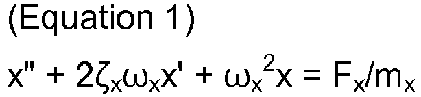

- 0058 The cutting forces Fx and Fy can be calculated by the following
equations 3 and 4, respectively:

- 0059 The cutting forces Fx and Fy change in accordance with an angle of rotation ϕ [rad] of the tool T; therefore, the cutting forces Fx and Fy can be respectively obtained by integrating the cutting force Fx, Fy between an angle ϕst at which cutting is started and an angle ϕex at which the cutting is ended and calculating the mean value thereof. Further, the angle ϕst and the angle ϕex can be geometrically determined based on a diameter D [mm] of the tool T, a width of cut Ae [mm], the feed direction, and whether the cutting is upper cut or down cut.
- 0060 An eigenvalue Λ of the above equations 1 and 2 is represented by the following equation 5:


- 0061 When a real part and an imaginary part of the eigenvalue Λ are represented by ΛR and ΛI, respectively, a depth of cut aplim and a spindle rotation speed nlim at a stability limit are represented by the following
equations 

- 0062 By calculating the limit depth of cut aplim and the spindle rotation speed nlim by the
above equations Fig. 3 can be created. - 0063 Note that the natural frequencies ωx and ωy can be experimentally obtained through a striking test using a hammer, and the cutting rigidity Kt and the specific cutting rigidity Kr can be obtained through trial machining.
- 0064 Further, the damping ratios ζx and ζy can be calculated, for example, by the following
equations 8 and 9, respectively:

Note that, as shown inFig. 9 , ω1x and ω2x are frequencies corresponding to Gx/21/2 when the largest value of a compliance (displacement (= output) / cutting force (= input)) in the x-axis direction is Gx, and ω1y and ω2y are frequencies corresponding to Gy/21/2 when the largest value of a compliance in the y-axis direction is Gy, and the frequency when the compliance in the x-axis direction is the largest value Gx and the frequency when the compliance in the y-axis direction is the largest value Gy are the natural frequencies ωx and ωy of the tool T, respectively. - 0065 Further, the equivalent masses mx and my can be calculated by the following
equations 

- 0066 Note that the stability lobe differs in accordance with tool type, tool material, and workpiece material; therefore, a stability lobe is obtained in advance with respect to each tool type, each tool material, and each workpiece material in the above-described manner, and the obtained stability lobes are stored in the stability
lobe data storage 10 with respect to each tool type, each tool material, and each workpiece material. - 0067 The achievement degree display picture creator 3 is configured to receive, from the
input device 8 and theinput controller 7, selection signals for selecting a tool type, a tool material, and a workpiece material, a selection signal for selecting one from the evaluation items, and a signal relating to a required degree of achievement for the selected evaluation item. Note that these signals are input by an operator through theinput device 8. - 0068 Upon receiving the selection signals and the signal relating to the required degree of achievement, the achievement degree display picture creator 3 refers to a data table corresponding to the selected tool type, tool material, and workpiece material from among the data tables stored in the achievement degree data storage 9, and refers to stability lobe data corresponding to the selected tool type, tool material, and workpiece material from among the data stored in the stability
lobe data storage 10. Thereby, the achievement degree display picture creator 3 creates a display picture for displaying a set of machining conditions corresponding to the required degree of achievement for the selected evaluation item as well as the degrees of achievement of the evaluation items to be obtained under the set of machining conditions, and displays the created display picture on thedisplay device 5 via thedisplay controller 4. - 0069 Hereinafter, a mode of the creation of a display picture in the achievement degree display picture creator 3 and display of the display picture on the
display device 5 will be described in detail. - 0070 First, by referring to the data table corresponding to the selected tool type, tool material, and workpiece material, the achievement degree display picture creator 3 recognizes a set of machining conditions corresponding to the required degree of achievement for the selected evaluation item. Further, by referring to the stability lobe data corresponding to the selected tool type, tool material, and workpiece material, the achievement degree display picture creator 3 examines whether the recognized set of machining conditions falls within the stable area limited by the stability lobe. In the case where the set of machining conditions falls within the stable area, the achievement degree display picture creator 3 recognizes the degrees of achievement of the evaluation items to be obtained under the set of machining conditions, by referring to the data table.
- 0071 For example, in a case where the referred data table is the data table shown in
Fig. 2 , the selected evaluation item is "machining time", and the required degree of achievement therefor is "90", the achievement degree display picture creator 3 recognizes, as a set of machining conditions corresponding thereto, the set of machining conditions in which "feed rate" is "max", "cutting speed" is "max", "width of cut" is "middle", and "depth of cut" is "min", and reads out the degrees of achievement of the evaluation items corresponding to this set of machining conditions. Note that, in this case, the degree of achievement of "surface roughness" is "45", the degree of achievement of "tool life" is "22", the degree of achievement of "cutting efficiency" is "60", the degree of achievement of "residual stress" is "6", and the degree of achievement of "spindle motor load" is "8", and the degree of achievement of "feed motor load" is "6". - 0072 In contrast, in the case where the recognized set of machining conditions does not fall within the stable area limited by the stability lobe, the achievement degree display picture creator 3 selects a set of machining conditions which falls within the stable area, and reads out the degrees of achievement of the evaluation items corresponding to the selected set of machining conditions by referring to the data table. Note that, in changing the set of machining conditions, change is made to both of "cutting speed" and "depth of cut" or either one of them.
- 0073 Subsequently, the achievement degree display picture creator 3 creates a display picture showing the read-out set of machining conditions and degrees of achievement of the evaluation items. In such a display picture, as shown in
Fig. 4 , the degrees of achievement of the evaluation items are shown by means of figures, and a column for showing the corresponding set of machining conditions by means of characters is provided below the figures representing the degrees of achievement. - 0074 The figures representing the degree of achievement of each evaluation item consist of an axial figure having a length corresponding to the range determined by the maximum and minimum values of the evaluation item, and an index figure (black rectangular figure) arranged on the axial figure at a length position corresponding to a proportion corresponding to the degree of achievement of the evaluation item. In this example, the axial figure for each evaluation item has a length defining the maximum value as level "100" and the minimum value as level "0", the axial figures have the same length. Further, at the left of each axial figure, the corresponding evaluation item is shown by means of characters. In
Fig. 4 , the set of machining conditions read out in the above-described manner, in which "feed rate" is "max", "cutting speed" is "max", "width of cut" is "middle", "depth of cut" is "min", is displayed, and the index figures for the case where the degree of achievement of "machining time" is "90", the degree of achievement of "surface roughness" is "45", the degree of achievement of "tool life" is "22", the degree of achievement of "cutting efficiency" is "60", the degree of achievement of "residual stress" is "6", the degree of achievement of "spindle motor load" is "8", and the degree of achievement of "feed motor load" is "6" are displayed. - 0075 Data relating to the display picture created by the achievement degree display picture creator 3 in the above-described manner is transmitted to the
display controller 4, and the display picture is displayed on thedisplay device 5 under control by thedisplay controller 4. - 0076 As described above, with the machining
state display apparatus 1 according to this embodiment, once an operator inputs a tool type, a tool material, and a workpiece material which he desires to be displayed, as well as an evaluation item to be noted and a required degree of achievement for the evaluation item, with respect to machining using the desired tool type, tool material, and workpiece material, a set of machining conditions which satisfies the required degree of achievement for the evaluation item to be noted is displayed and the degrees of achievement of the evaluation items to be obtained under the set of machining conditions are displayed by means of the figures. Therefore, the operator can instantaneously and intuitively recognize the degrees of achievement of the evaluation items. Further, the operator can recognize the degree of achievement of the evaluation item to be noted as well as the degrees of achievement of other evaluation items and can easily recognize a relationship between the evaluation items; therefore, the operator can easily recognize a set of machining conditions which provides such degrees of achievement. - 0077 Further, the operator can adjust the degrees of achievement of the evaluation items by adjusting the required degree of achievement that he inputs through the
input device 8. Such adjustment allows the operator to easily recognize, for example, a set of machining conditions under which the degrees of achievement of the evaluation items are well-balanced or a set of machining conditions under which the degrees of achievement of the evaluation items are in his desired state. Further, since the evaluation items are related to machining efficiency, machining costs, and machining accuracy, adjusting the degrees of achievement of the evaluation items allows the operator to obtain a preferable set of machining conditions which comprehensively takes into account machining efficiency, machining costs, and machining accuracy. - 0078 Further, with this machining
state display apparatus 1, in the case where the set of machining conditions corresponding to the required degree of achievement for the selected evaluation item does not fall within the stable area limited by the stability lobe, another set of machining conditions which falls within the stable area is selected, and the selected set of machining conditions and the degrees of achievement of the evaluation items corresponding to the selected set of machining conditions are displayed. Therefore, the operator can obtain a set of machining conditions which causes no regenerative chatter, without being required to perform a special operation. - 0079 Note that, in the machining
state display apparatus 1 according to this embodiment, theinput device 8 may be configured to be able to, in the state where a picture showing the degrees of achievement has been displayed on thedisplay device 5 in the above-described manner, via theinput controller 7 and thedisplay controller 4, input a selection signal for selecting one from the index figures for the evaluation items displayed on thedisplay device 5 and input a signal for sliding the selected index figure in a longitudinal direction of the axial figure corresponding thereto. - 0080 In such a case, the
display controller 4 is configured to, when the selection signal and the sliding signal are input from theinput device 8 via theinput controller 7, recognize the evaluation item corresponding to the selection signal and transmit a signal relating to the evaluation item to theinput controller 8. Further, thedisplay controller 4 is configured to slide the index figure displayed on thedisplay device 5 in accordance with the sliding signal, and recognize a degree of achievement corresponding to a position at which the index figure is stopped and transmit a signal relating to the recognized degree of achievement to theinput controller 7. Theinput controller 7 is configured to transmit, to the achievement degree display picture creator 3, the signal relating to the evaluation item (i.e., signal relating to the changed selected evaluation item) and signal relating to the degree of achievement (signal relating to the changed required degree of achievement) transmitted from thedisplay controller 4. - 0081 Upon receiving the signal relating to the changed selected evaluation item and the signal relating to the changed required degree of achievement from the
input controller 7 in the above-described manner, the achievement degree display picture creator 3 creates an updated display picture by performing the above-described steps again, and transmits data relating to the updated display picture to thedisplay controller 4 to display the updated display picture on thedisplay device 5 under control by thedisplay controller 4. - 0082 With the thus-configured machining
state display apparatus 1, a selection signal is input when an operator selects one from the index figures for the evaluation items displayed on thedisplay device 5 through theinput device 8, and a required degree of achievement is input when the operator slides the selected index figure in the longitudinal direction of the axial figure corresponding thereto. Therefore, the operator can easily adjust the required degree of achievement to be input and easily adjust the degrees of achievement of the evaluation items. - 0083 Further, in the machining
state display apparatus 1 according to this embodiment, the achievement degree display picture creator 3 may be configured to, in a case where two or more sets of machining conditions exist which satisfy the required degree of achievement for the selected evaluation item input from theinput controller 7, recognize an optimum set of machining conditions under which the degree of achievement of another evaluation item (evaluation item different from the selected evaluation item) of high priority, which is previously determined in relation to the selected evaluation item, is greatest, then recognize the degrees of achievement of other evaluation items to be obtained under the optimum set of machining conditions, and create a display picture as described above. - 0084 Further, in such a case, the achievement degree display picture creator 3 may be configured to, in the display picture, with respect to a non-target degree of achievement of the evaluation items other than the degrees of achievement corresponding to the index figures of the degrees of achievement of the evaluation items to be obtained under the existing sets of machining conditions, in other words, with respect to each of the degrees of achievement of the evaluation items to be obtained under the existing sets of machining conditions other than the optimum set of machining conditions, arrange a regional figure on the axial figure corresponding thereto, the regional figure including a length position corresponding to a proportion corresponding to the degree of achievement and connecting to the index figure.
- 0085 For example, in
Fig. 2 , in a case where the selected evaluation item is "machining time" and the required degree of achievement is "94", two sets of machining conditions satisfy the required degree of achievement: a first set of machining conditions in which "feed rate" is "max", "cutting speed" is "max", "width of cut" is "max", and "depth of cut" is "min", and a second set of machining conditions in which "feed rate" is "max", "cutting speed" is "max", "width of cut" is "middle", and "depth of cut" is "middle". - 0086 In this case, the achievement degree display picture creator 3 selects the set of machining conditions under which the degree of achievement of the predetermined high-priority evaluation item, for example, "surface roughness", is greater, i.e., the first set of machining conditions under which the degree of achievement of "surface roughness" is "45", reads out the degrees of achievement of the other evaluation items to be obtained under the first set of machining conditions, and creates a display picture as described above. Further, in the case where there is an evaluation item having a different degree of achievement under the second set of machining conditions from the one under the first set of machining conditions, the achievement degree display picture creator 3 arranges, in the display picture, with respect to the evaluation item, a regional figure on the axial figure corresponding thereto, the regional figure including a length position corresponding to a proportion corresponding to the degree of achievement to be obtained under the second set of machining conditions (non-target degree of achievement) and connecting to the index figure. In the example shown in
Fig. 2 , the degree of achievement "42" of "surface roughness" and the degree of achievement "25" of "tool life" are non-target degrees of achievement. A display picture created in this manner is shown inFig. 5 . InFig. 5 , the regional figures are shown by white rectangular figures. - 0087 With the thus-configured machining
state display apparatus 1, in the case where there are two or more sets of machining conditions corresponding to the required degree of achievement for the selected evaluation item, with respect to each of the evaluation items, the degrees of achievement under the sets of machining conditions are shown by the index figure and the regional figure connecting thereto. Therefore, the operator can recognize, which respect to each evaluation item, the degree of achievement corresponding to the index figure as well as another attainable degree of achievement. Further, because the operator can obtain such recognition, he can easily obtain a set of machining conditions which provides preferable degrees of achievement for the evaluation items, that is, a preferable set of machining conditions which comprehensively takes into account machining efficiency, machining costs, and machining accuracy. - 0088 Further, in the machining
state display apparatus 1 according to this embodiment, the achievement degree display picture creator 3 may be configured to, in the above-mentioned case where two or more sets of machining conditions exist which satisfy the required degree of achievement for the selected evaluation item, if still another evaluation item that is different from the high-priority evaluation item has a greater degree of achievement under a different set of machining conditions from the optimum set of machining conditions than under the optimum set of machining conditions, with respect to the still another evaluation item, display a figure representing the degree of achievement to be obtained under the different set of machining conditions and a figure representing the degree of achievement to be obtained under the optimum set of machining conditions with the figures associated with each other. - 0089 For example, in
Fig. 2 , similarly to the above, in the case where the selected evaluation item is "machining time" and the required degree of achievement therefor is "94", two sets of machining conditions, i.e., the first set of machining conditions and the second set of machining conditions, satisfy the required degree of achievement, and the first set of machining conditions under which the degree of achievement of "surface roughness" that is the high-priority evaluation item is greater is selected as a set of machining conditions to be applied. Thereafter, the achievement degree display picture creator 3 reads out the degrees of achievement of the evaluation items to be obtained under the first set of machining conditions and creates a display picture therefor. In this process, with respect to an evaluation item having a greater degree of achievement under the second set of machining conditions than under the first set of machining conditions, the achievement degree display picture creator 3 designates the degree of achievement to be obtained under the second set of machining conditions as a non-target degree of achievement, and arranges a reference index figure as an index for reference on the axial figure corresponding thereto at a length position corresponding to a proportion corresponding to the non-target degree of achievement. The degree of achievement of "residual stress" to be obtained under the second set of machining conditions is "6", which is greater than the degree of achievement "4" thereof to be obtained under the first set of machining conditions. In this case, as shown inFig. 6 , with respect to "residual stress" a reference index figure corresponding to the degree of achievement "6" to be obtained under the second set of machining conditions is shown together with the index figure corresponding to the degree of achievement "4" to be obtained under the first set of machining conditions. Note that, inFig. 6 , the reference index figure is shown by a hatched rectangular figure. - 0090 With the thus-configured machining
state display apparatus 1, in the case where the degree of achievement of still another evaluation item that is different from the high-priority evaluation item is greater under a different set of machining conditions from the optimum set of machining conditions than under the optimum set of machining conditions, with respect to the still another evaluation item, a figure representing the degree of achievement to be obtained under the different set of machining conditions and a figure representing the degree of achievement to be obtained under the optimum set of machining conditions are displayed in association with each other. Therefore, by referring to the figures, the operator can easily recognize not only a set of machining conditions prioritizing the predetermined high-priority evaluation item, but also whether there is another preferable set of machining conditions, which allows the operator to obtain a more preferable set of machining conditions. - 0091 Further, in the machining
state display apparatus 1 according to this embodiment, the achievement degree display picture creator 3 may be configured, when creating the display picture, recognize an unstable set of machining conditions which falls within an unstable area limited by the stability lobe based on the selected stability lobe data and achievement degree data, examine, based on the recognized unstable set of machining conditions, with respect to each of the evaluation items, whether an inapplicable degree of achievement exists, and, in the case where an inapplicable degree of achievement exits, arrange a figure corresponding to the inapplicable degree of achievement on the axial figure for the evaluation item corresponding thereto. An example of such a display picture is shown inFig. 7 . InFig. 7 , white rectangular figures sounded by dashed lines represent inapplicable ranges. Note that, as a matter of course, the embodiments shown inFigs. 4 and6 may be configured to display such a figure corresponding to an inapplicable degree of achievement. - 0092 With this machining
state display apparatus 1, the operator can easily recognize whether the displayed degrees of achievement of the evaluation items are inapplicable. Further, under such recognition, the operator can select a set of machining conditions which does not provide inapplicable degrees of achievement for the evaluation items, by adjusting the required degree of achievement for the selected evaluation item as appropriate. - 0093 Hereinbefore, a specific embodiment of the present invention has been described. However, the present invention is not limited thereto and may be implemented in other modes.
- 0094 Although the achievement degree display picture creator 3 in the above embodiment is configured to create a display picture in which the degrees of achievement are displayed by means of figures, the achievement degree display picture creator 3 may be configured to create a display picture in which the degrees of achievement are displayed by means of characters. In such a case, also as for the above-described regional figure, reference index figure, and figure corresponding to the inapplicable degree of achievement, it is preferable that the degree of achievement, range, or the like corresponding thereto is displayed by means of characters with respect to each evaluation item.
- 0095
- 1
- Machining state display apparatus
- 2
- Display part
- 3
- Achievement degree display picture creator
- 4
- Display controller
- 5
- Display device
- 6
- Input part
- 7
- Input controller
- 8
- Input device
- 9
- Achievement degree data storage
- 10
- Stability lobe data storage
- 11
- Computing device
Claims (9)
- A machining state display apparatus, comprising:an achievement degree data storage storing machining condition data relating to each of a plurality of predetermined sets of machining conditions and achievement degree data relating to degrees of achievement of a plurality of predetermined machining-related evaluation items to be obtained in machining under each of the plurality of sets of machining conditions with the machining condition data and the achievement degree data associated with each other, the achievement degree data indicating the degree of achievement of each of the evaluation items within a range determined by attainable maximum and minimum values of the evaluation item;a display part having a display and displaying, on the display, a set of machining conditions and the degrees of achievement of the evaluation items corresponding to the set of machining conditions by referring to the machining condition data and achievement degree data stored in the achievement degree data storage; andan input part inputting a selection signal for selecting one from the plurality of evaluation items and a required degree of achievement for the selected evaluation item, characterized in thatthe display part is further configured to, when the selection signal and the required degree of achievement are input from the input part, recognize, based on the selected evaluation item and the required degree of achievement, a set of machining conditions corresponding to the required degree of achievement for the selected evaluation item as well as the degrees of achievement of other evaluation items to be obtained under the set of machining conditions by referring to the achievement degree data and machining condition data stored in the achievement degree data storage, and display the degree of achievement of the input evaluation item and the recognized degrees of achievement of the other evaluation items on evaluation-item basis and display the recognized set of machining conditions.
- The machining state display apparatus according to claim 1, characterized in that
the display part is configured to,
in a case where, as a result of referring to the achievement degree data stored in the achievement degree data storage, there are two or more sets of machining conditions corresponding to the required degree of achievement for the selected evaluation item,
recognize an optimum set of machining conditions under which the degree of achievement of a high-priority evaluation item of the other evaluation items is greatest, the high-priority evaluation item being previously determined in relation to the selected evaluation item,
subsequently, recognize the degrees of achievement of the other evaluation items to be obtained under the optimum set of machining conditions, and
display the degree of achievement of the input evaluation item and the recognized degrees of achievement of the other evaluation items on evaluation-item basis and display the recognized optimum set of machining conditions. - The machining state display apparatus according to claim 1 or 2, characterized in that the display part is configured to display the degree of achievement of each of the evaluation items by means of figures, the figures consisting of an axial figure having a length corresponding to the range determined by the maximum and minimum values of the evaluation item, and an index figure arranged on the axial figure at a length position corresponding to a proportion corresponding to the degree of achievement.
- The machining state display apparatus according to claim 1 or 2, characterized in that:the display part is configured to display the degree of achievement of each of the evaluation items by means of figures, the figures including an axial figure having a length corresponding to the range determined by the maximum and minimum values of the evaluation item, and an index figure arranged on the axial figure at a length position corresponding to a proportion corresponding to the degree of achievement; andthe display part is further configured to, in a case where, as a result of referring to the achievement degree data stored in the achievement degree data storage, there are two or more sets of machining conditions corresponding to the required degree of achievement for the selected evaluation item, with respect to a non-target degree of achievement other than the degrees of achievement corresponding to the index figures of the degrees of achievement of the evaluation items to be obtained under the two or more sets of machining conditions, display a regional figure arranged on the axial figure, the regional figure including a length position corresponding to a proportion corresponding to the non-target degree of achievement and connecting to the index figure.
- The machining state display apparatus according to claim 2, characterized in that:the display part is configured to display the degree of achievement of each of the evaluation items by means of figures, the figures including an axial figure having a length corresponding to the range determined by the maximum and minimum values of the evaluation item, and an index figure arranged on the axial figure at a length position corresponding to a proportion corresponding to the degree of achievement; andthe display part is further configured to, in a case where, as a result of referring to the achievement degree data stored in the achievement degree data storage, the degree of achievement of still another evaluation item different from the high-priority evaluation item is greater under a different set of machining conditions from the optimum set of machining conditions than under the optimum set of machining conditions, with respect to the still another evaluation item, display a figure representing the degree of achievement to be obtained under the different set of machining conditions and a figure representing the degree of achievement to be obtained under the optimum set of machining conditions with these figures associated with each other.
- The machining state display apparatus according to any one of claims 3 to 5, characterized in that:the input part is configured to be able to input a selection signal for selecting one from the index figures for the evaluation items displayed on the display and input a sliding signal for sliding the selected index figure in a longitudinal direction of the axial figure corresponding thereto; andthe display part is configured to, when the selection signal and the sliding signal are input from the input part, recognize the evaluation item corresponding to the selection signal and slide the index figure displayed on the display in accordance with the sliding signal, and recognize a required degree of achievement based on a position at which the index figure is stopped.
- The machining state display apparatus according to any one of claims 1 to 6, characterized in that:the machining state display apparatus further comprises a stability lobe data storage storing stability lobe data relating to regenerative chatter of a tool in a correlation between relative rotation speed between the tool and an object to be machined and cutting amount of the tool; andthe display part is configured to,based on the stability lobe data stored in the stability lobe data storage, examine whether the set of machining conditions corresponding to the required degree of achievement falls within a stable area limited by the stability lobe,in a case where the set of machining conditions corresponding to the required degree of achievement falls within the stable area, display the set of machining conditions and the degrees of achievement of the evaluation items to be obtained under the set of machining conditions,in a case where the set of machining conditions corresponding to the required degree of achievement does not fall within the stable area, select a set of machining conditions falling within the stable area and recognize the degrees of achievement of the evaluation items corresponding to the selected set of machining conditions by referring to the data stored in the achievement degree data storage, and display the selected set of machining conditions and the recognized degrees of achievement of the evaluation items.
- The machining state display apparatus according to claim 1 or 2, characterized in that:the machining state display apparatus further comprises a stability lobe data storage storing stability lobe data relating to regenerative chatter of a tool in a correlation between relative rotation speed between the tool and an object to be machined and cutting amount of the tool; andthe display part is configured to,based on the stability lobe data stored in the stability lobe data storage and the data stored in the achievement degree data storage, recognize an unstable set of machining conditions falling within an unstable area limited by the stability lobe,based on the recognized unstable set of machining conditions, with respect to each of the evaluation items, examine whether an inapplicable degree of achievement exists, andin a case where an inapplicable degree of achievement exists, display the inapplicable degree of achievement with respect to the evaluation item corresponding thereto.
- The machining state display apparatus according to any one of claims 3 to 6, characterized in that:the machining state display apparatus further comprises a stability lobe data storage storing stability lobe data relating to regenerative chatter of a tool in a relationship between relative rotation speed between the tool and an object to be machined and cutting amount of the tool; andthe display part is configured to,based on the stability lobe data stored in the stability lobe data storage and the data stored in the achievement degree data storage, recognize an unstable set of machining conditions falling within an unstable area limited by the stability lobe,based on the recognized unstable set of machining conditions, with respect to each of the evaluation items, examine whether an inapplicable degree of achievement exists, andin a case where an inapplicable degree of achievement exists, display a figure corresponding to the inapplicable degree of achievement, with the figure arranged on the axial figure for the evaluation item corresponding thereto.
Applications Claiming Priority (2)
| Application Number | Priority Date | Filing Date | Title |
|---|---|---|---|
| JP2016107575A JP6371335B2 (en) | 2016-05-30 | 2016-05-30 | Processing status display device |
| PCT/JP2017/010842 WO2017208571A1 (en) | 2016-05-30 | 2017-03-17 | Machining state display apparatus |
Publications (3)
| Publication Number | Publication Date |
|---|---|
| EP3454146A1 true EP3454146A1 (en) | 2019-03-13 |
| EP3454146A4 EP3454146A4 (en) | 2020-08-26 |
| EP3454146B1 EP3454146B1 (en) | 2024-07-24 |
Family
ID=60479516
Family Applications (1)
| Application Number | Title | Priority Date | Filing Date |
|---|---|---|---|
| EP17806133.9A Active EP3454146B1 (en) | 2016-05-30 | 2017-03-17 | Machining state display apparatus |
Country Status (5)
| Country | Link |
|---|---|
| US (1) | US10987775B2 (en) |
| EP (1) | EP3454146B1 (en) |
| JP (1) | JP6371335B2 (en) |
| CN (1) | CN108604089B (en) |
| WO (1) | WO2017208571A1 (en) |
Cited By (2)
| Publication number | Priority date | Publication date | Assignee | Title |
|---|---|---|---|---|
| WO2021123216A1 (en) * | 2019-12-20 | 2021-06-24 | Trumpf Werkzeugmaschinen Gmbh + Co. Kg | Method and device for determining cutting parameters for a laser cutting machine |
| EP4636516A1 (en) * | 2024-04-18 | 2025-10-22 | GF Machining Solutions AG | A method of generating parameters applied for machining a workpiece performed by a machine tool |
Families Citing this family (9)
| Publication number | Priority date | Publication date | Assignee | Title |
|---|---|---|---|---|
| JP6599956B2 (en) | 2017-10-23 | 2019-10-30 | ファナック株式会社 | Machine tool machining condition selection device |
| JP6770018B2 (en) | 2018-04-12 | 2020-10-14 | ファナック株式会社 | Setting device and setting program |
| JP6802213B2 (en) * | 2018-04-26 | 2020-12-16 | ファナック株式会社 | Tool selection device and machine learning device |
| JP7287845B2 (en) * | 2019-06-26 | 2023-06-06 | ファナック株式会社 | MACHINE TOOL SEARCH DEVICE, MACHINE TOOL SEARCH METHOD AND MACHINE TOOL SEARCH PROGRAM |
| JP6826230B1 (en) * | 2020-10-21 | 2021-02-03 | Dmg森精機株式会社 | Evaluation device and program |
| CN116348242A (en) * | 2020-10-28 | 2023-06-27 | 发那科株式会社 | Tool path optimizing device and optimizing program |
| CN115971970B (en) * | 2022-12-02 | 2024-03-26 | 西南交通大学 | A milling cutter wear monitoring method based on multi-parameter guided spatial attention mechanism |
| CN115771061B (en) * | 2022-12-02 | 2024-03-26 | 西南交通大学 | A milling cutter wear monitoring method based on frequency attention mechanism |
| CN117075533B (en) * | 2023-09-06 | 2024-07-12 | 青岛亿瑞佳机械有限公司 | Control system and method for numerical control machine tool |
Family Cites Families (13)
| Publication number | Priority date | Publication date | Assignee | Title |
|---|---|---|---|---|
| JPH07295619A (en) * | 1994-04-25 | 1995-11-10 | Mitsubishi Electric Corp | Numerical control device for machine tools |
| JP3068032B2 (en) * | 1997-04-28 | 2000-07-24 | 三菱電機株式会社 | Slide bar display control device |
| JP4282157B2 (en) * | 1999-06-21 | 2009-06-17 | 株式会社東芝 | Machining condition evaluation / verification equipment |
| EP1308810B1 (en) * | 2001-09-05 | 2005-11-16 | Mikron Comp-Tec AG | A method and an operator support system for assisting an operator in setting machine parameters |
| JP2004280267A (en) * | 2003-03-13 | 2004-10-07 | Sumitomo Heavy Ind Ltd | Display device for working device, display method for the working device, display program for the working device, and recording medium |
| JP2007069330A (en) * | 2005-09-08 | 2007-03-22 | Fanuc Ltd | Machining condition setting method of electrical discharge machining device |
| JP5631792B2 (en) * | 2011-03-28 | 2014-11-26 | オークマ株式会社 | Machine tool monitoring device |
| JP5661832B2 (en) * | 2013-02-26 | 2015-01-28 | ファナック株式会社 | Waveform display device with search function according to setting conditions |
| JP6178591B2 (en) * | 2013-03-06 | 2017-08-09 | 富士機械製造株式会社 | Tool abnormality discrimination system |
| JP5670501B2 (en) * | 2013-03-21 | 2015-02-18 | ファナック株式会社 | Cutting condition display device |
| DE102013211860A1 (en) * | 2013-06-21 | 2014-12-24 | Christof Ellerbrock | Device for a parameterizable processing device |
| DE102014216593A1 (en) | 2014-08-21 | 2016-02-25 | Deere & Company | Operator assistance system for an agricultural working machine |
| JP6599956B2 (en) * | 2017-10-23 | 2019-10-30 | ファナック株式会社 | Machine tool machining condition selection device |
-
2016
- 2016-05-30 JP JP2016107575A patent/JP6371335B2/en active Active
-
2017
- 2017-03-17 WO PCT/JP2017/010842 patent/WO2017208571A1/en not_active Ceased
- 2017-03-17 EP EP17806133.9A patent/EP3454146B1/en active Active
- 2017-03-17 US US16/095,988 patent/US10987775B2/en active Active
- 2017-03-17 CN CN201780008968.0A patent/CN108604089B/en active Active
Cited By (3)
| Publication number | Priority date | Publication date | Assignee | Title |
|---|---|---|---|---|
| WO2021123216A1 (en) * | 2019-12-20 | 2021-06-24 | Trumpf Werkzeugmaschinen Gmbh + Co. Kg | Method and device for determining cutting parameters for a laser cutting machine |
| US12504740B2 (en) | 2019-12-20 | 2025-12-23 | TRUMPF Werkzeugmaschinen SE + Co. KG | Method and apparatus for determining cutting parameters for a laser cutting machine |
| EP4636516A1 (en) * | 2024-04-18 | 2025-10-22 | GF Machining Solutions AG | A method of generating parameters applied for machining a workpiece performed by a machine tool |
Also Published As
| Publication number | Publication date |
|---|---|
| US10987775B2 (en) | 2021-04-27 |
| JP6371335B2 (en) | 2018-08-08 |
| JP2017215675A (en) | 2017-12-07 |
| EP3454146B1 (en) | 2024-07-24 |
| CN108604089A (en) | 2018-09-28 |
| CN108604089B (en) | 2021-08-27 |
| EP3454146A4 (en) | 2020-08-26 |
| US20190134767A1 (en) | 2019-05-09 |
| WO2017208571A1 (en) | 2017-12-07 |
Similar Documents
| Publication | Publication Date | Title |
|---|---|---|
| EP3454146B1 (en) | Machining state display apparatus | |
| US10386831B2 (en) | Machining status display apparatus | |
| EP2821870B1 (en) | Setting method of revolutions per minute on real time of rotating cutting tool, and control device | |
| JPH01234135A (en) | Method of controlling machine tool | |
| US20170153208A1 (en) | Method Of Deriving Natural Frequency Of Cutting Tool, Method Of Creating Stability Limit Curve, And Apparatus For Deriving Natural Frequency Of Cutting Tool | |
| Altintas et al. | Virtual high performance milling | |
| US10386814B2 (en) | Machining status display apparatus, and NC program generating apparatus and NC program editing apparatus provided with the same | |
| JP7392281B2 (en) | Work support system | |
| JP5917251B2 (en) | Chatter vibration suppression system and suppression method | |
| US9651936B2 (en) | Machining method | |
| Song et al. | Subdivision of chatter-free regions and optimal cutting parameters based on vibration frequencies for peripheral milling process | |
| CN109696147A (en) | The processing conditions selecting apparatus of lathe | |
| Govekar et al. | On stability and dynamics of milling at small radial immersion | |
| Salehi et al. | Epicycloidal versus trochoidal milling-comparison of cutting force, tool tip vibration, and machining cycle time | |
| CN110102787A (en) | A chatter suppression method for turning with variable spindle speed based on amplitude modulation | |
| JP6295040B2 (en) | Simulation apparatus, simulation method, and biaxial cutting machine | |
| CN107571097B (en) | Processing status display device | |
| EP4390588A1 (en) | Machining environment assist system and machining environment assist method | |
| JP2012200848A (en) | Monitor device for machine tool | |
| US12455554B2 (en) | Assistance device for analyzing machining conditions of a machine tool | |
| JP6505145B2 (en) | Stability limit diagram drawing device and stability limit diagram drawing method | |
| Kilic et al. | Stability of peripheral milling operations with long end mills | |
| Insperger et al. | The effect of runout on the chatter frequencies of milling processes | |
| Fazelinia et al. | New perspective in process optimisation of variable pitch milling | |
| WO2023281627A1 (en) | Display device, machine tool and display method |
Legal Events
| Date | Code | Title | Description |
|---|---|---|---|
| STAA | Information on the status of an ep patent application or granted ep patent |
Free format text: STATUS: THE INTERNATIONAL PUBLICATION HAS BEEN MADE |
|
| PUAI | Public reference made under article 153(3) epc to a published international application that has entered the european phase |
Free format text: ORIGINAL CODE: 0009012 |
|
| STAA | Information on the status of an ep patent application or granted ep patent |
Free format text: STATUS: REQUEST FOR EXAMINATION WAS MADE |
|
| 17P | Request for examination filed |
Effective date: 20181207 |
|
| AK | Designated contracting states |
Kind code of ref document: A1 Designated state(s): AL AT BE BG CH CY CZ DE DK EE ES FI FR GB GR HR HU IE IS IT LI LT LU LV MC MK MT NL NO PL PT RO RS SE SI SK SM TR |
|
| AX | Request for extension of the european patent |
Extension state: BA ME |
|
| DAV | Request for validation of the european patent (deleted) | ||
| DAX | Request for extension of the european patent (deleted) | ||
| RIC1 | Information provided on ipc code assigned before grant |
Ipc: G05B 19/4063 20060101AFI20200207BHEP Ipc: G05B 19/4093 20060101ALI20200207BHEP |
|
| RIC1 | Information provided on ipc code assigned before grant |
Ipc: G05B 19/4063 20060101AFI20200624BHEP Ipc: G05B 19/4093 20060101ALI20200624BHEP |
|
| A4 | Supplementary search report drawn up and despatched |
Effective date: 20200724 |
|
| RIC1 | Information provided on ipc code assigned before grant |
Ipc: G05B 19/4063 20060101AFI20200720BHEP Ipc: G05B 19/4093 20060101ALI20200720BHEP |
|
| STAA | Information on the status of an ep patent application or granted ep patent |
Free format text: STATUS: EXAMINATION IS IN PROGRESS |
|
| 17Q | First examination report despatched |
Effective date: 20211126 |
|
| GRAP | Despatch of communication of intention to grant a patent |
Free format text: ORIGINAL CODE: EPIDOSNIGR1 |
|
| STAA | Information on the status of an ep patent application or granted ep patent |
Free format text: STATUS: GRANT OF PATENT IS INTENDED |
|
| INTG | Intention to grant announced |
Effective date: 20240229 |
|
| GRAS | Grant fee paid |
Free format text: ORIGINAL CODE: EPIDOSNIGR3 |
|
| GRAA | (expected) grant |
Free format text: ORIGINAL CODE: 0009210 |
|
| STAA | Information on the status of an ep patent application or granted ep patent |
Free format text: STATUS: THE PATENT HAS BEEN GRANTED |
|
| AK | Designated contracting states |
Kind code of ref document: B1 Designated state(s): AL AT BE BG CH CY CZ DE DK EE ES FI FR GB GR HR HU IE IS IT LI LT LU LV MC MK MT NL NO PL PT RO RS SE SI SK SM TR |
|
| REG | Reference to a national code |
Ref country code: GB Ref legal event code: FG4D |
|
| REG | Reference to a national code |
Ref country code: CH Ref legal event code: EP |
|
| REG | Reference to a national code |
Ref country code: DE Ref legal event code: R096 Ref document number: 602017083552 Country of ref document: DE |
|
| REG | Reference to a national code |
Ref country code: IE Ref legal event code: FG4D |
|
| REG | Reference to a national code |
Ref country code: LT Ref legal event code: MG9D |
|
| REG | Reference to a national code |
Ref country code: NL Ref legal event code: MP Effective date: 20240724 |
|
| PG25 | Lapsed in a contracting state [announced via postgrant information from national office to epo] |
Ref country code: PT Free format text: LAPSE BECAUSE OF FAILURE TO SUBMIT A TRANSLATION OF THE DESCRIPTION OR TO PAY THE FEE WITHIN THE PRESCRIBED TIME-LIMIT Effective date: 20241125 |
|
| REG | Reference to a national code |
Ref country code: AT Ref legal event code: MK05 Ref document number: 1706878 Country of ref document: AT Kind code of ref document: T Effective date: 20240724 |
|
| PG25 | Lapsed in a contracting state [announced via postgrant information from national office to epo] |
Ref country code: NL Free format text: LAPSE BECAUSE OF FAILURE TO SUBMIT A TRANSLATION OF THE DESCRIPTION OR TO PAY THE FEE WITHIN THE PRESCRIBED TIME-LIMIT Effective date: 20240724 |
|
| PG25 | Lapsed in a contracting state [announced via postgrant information from national office to epo] |
Ref country code: PT Free format text: LAPSE BECAUSE OF FAILURE TO SUBMIT A TRANSLATION OF THE DESCRIPTION OR TO PAY THE FEE WITHIN THE PRESCRIBED TIME-LIMIT Effective date: 20241125 Ref country code: NL Free format text: LAPSE BECAUSE OF FAILURE TO SUBMIT A TRANSLATION OF THE DESCRIPTION OR TO PAY THE FEE WITHIN THE PRESCRIBED TIME-LIMIT Effective date: 20240724 |
|
| PG25 | Lapsed in a contracting state [announced via postgrant information from national office to epo] |
Ref country code: NO Free format text: LAPSE BECAUSE OF FAILURE TO SUBMIT A TRANSLATION OF THE DESCRIPTION OR TO PAY THE FEE WITHIN THE PRESCRIBED TIME-LIMIT Effective date: 20241024 |
|
| PG25 | Lapsed in a contracting state [announced via postgrant information from national office to epo] |
Ref country code: PL Free format text: LAPSE BECAUSE OF FAILURE TO SUBMIT A TRANSLATION OF THE DESCRIPTION OR TO PAY THE FEE WITHIN THE PRESCRIBED TIME-LIMIT Effective date: 20240724 Ref country code: FI Free format text: LAPSE BECAUSE OF FAILURE TO SUBMIT A TRANSLATION OF THE DESCRIPTION OR TO PAY THE FEE WITHIN THE PRESCRIBED TIME-LIMIT Effective date: 20240724 Ref country code: GR Free format text: LAPSE BECAUSE OF FAILURE TO SUBMIT A TRANSLATION OF THE DESCRIPTION OR TO PAY THE FEE WITHIN THE PRESCRIBED TIME-LIMIT Effective date: 20241025 |
|
| PG25 | Lapsed in a contracting state [announced via postgrant information from national office to epo] |
Ref country code: BG Free format text: LAPSE BECAUSE OF FAILURE TO SUBMIT A TRANSLATION OF THE DESCRIPTION OR TO PAY THE FEE WITHIN THE PRESCRIBED TIME-LIMIT Effective date: 20240724 |
|
| PG25 | Lapsed in a contracting state [announced via postgrant information from national office to epo] |
Ref country code: LV Free format text: LAPSE BECAUSE OF FAILURE TO SUBMIT A TRANSLATION OF THE DESCRIPTION OR TO PAY THE FEE WITHIN THE PRESCRIBED TIME-LIMIT Effective date: 20240724 |
|
| PG25 | Lapsed in a contracting state [announced via postgrant information from national office to epo] |
Ref country code: IS Free format text: LAPSE BECAUSE OF FAILURE TO SUBMIT A TRANSLATION OF THE DESCRIPTION OR TO PAY THE FEE WITHIN THE PRESCRIBED TIME-LIMIT Effective date: 20241124 Ref country code: AT Free format text: LAPSE BECAUSE OF FAILURE TO SUBMIT A TRANSLATION OF THE DESCRIPTION OR TO PAY THE FEE WITHIN THE PRESCRIBED TIME-LIMIT Effective date: 20240724 |
|
| PG25 | Lapsed in a contracting state [announced via postgrant information from national office to epo] |
Ref country code: HR Free format text: LAPSE BECAUSE OF FAILURE TO SUBMIT A TRANSLATION OF THE DESCRIPTION OR TO PAY THE FEE WITHIN THE PRESCRIBED TIME-LIMIT Effective date: 20240724 |
|
| PG25 | Lapsed in a contracting state [announced via postgrant information from national office to epo] |
Ref country code: RS Free format text: LAPSE BECAUSE OF FAILURE TO SUBMIT A TRANSLATION OF THE DESCRIPTION OR TO PAY THE FEE WITHIN THE PRESCRIBED TIME-LIMIT Effective date: 20241024 Ref country code: ES Free format text: LAPSE BECAUSE OF FAILURE TO SUBMIT A TRANSLATION OF THE DESCRIPTION OR TO PAY THE FEE WITHIN THE PRESCRIBED TIME-LIMIT Effective date: 20240724 |
|
| PG25 | Lapsed in a contracting state [announced via postgrant information from national office to epo] |
Ref country code: RS Free format text: LAPSE BECAUSE OF FAILURE TO SUBMIT A TRANSLATION OF THE DESCRIPTION OR TO PAY THE FEE WITHIN THE PRESCRIBED TIME-LIMIT Effective date: 20241024 Ref country code: PL Free format text: LAPSE BECAUSE OF FAILURE TO SUBMIT A TRANSLATION OF THE DESCRIPTION OR TO PAY THE FEE WITHIN THE PRESCRIBED TIME-LIMIT Effective date: 20240724 Ref country code: NO Free format text: LAPSE BECAUSE OF FAILURE TO SUBMIT A TRANSLATION OF THE DESCRIPTION OR TO PAY THE FEE WITHIN THE PRESCRIBED TIME-LIMIT Effective date: 20241024 Ref country code: LV Free format text: LAPSE BECAUSE OF FAILURE TO SUBMIT A TRANSLATION OF THE DESCRIPTION OR TO PAY THE FEE WITHIN THE PRESCRIBED TIME-LIMIT Effective date: 20240724 Ref country code: IS Free format text: LAPSE BECAUSE OF FAILURE TO SUBMIT A TRANSLATION OF THE DESCRIPTION OR TO PAY THE FEE WITHIN THE PRESCRIBED TIME-LIMIT Effective date: 20241124 Ref country code: HR Free format text: LAPSE BECAUSE OF FAILURE TO SUBMIT A TRANSLATION OF THE DESCRIPTION OR TO PAY THE FEE WITHIN THE PRESCRIBED TIME-LIMIT Effective date: 20240724 Ref country code: GR Free format text: LAPSE BECAUSE OF FAILURE TO SUBMIT A TRANSLATION OF THE DESCRIPTION OR TO PAY THE FEE WITHIN THE PRESCRIBED TIME-LIMIT Effective date: 20241025 Ref country code: FI Free format text: LAPSE BECAUSE OF FAILURE TO SUBMIT A TRANSLATION OF THE DESCRIPTION OR TO PAY THE FEE WITHIN THE PRESCRIBED TIME-LIMIT Effective date: 20240724 Ref country code: ES Free format text: LAPSE BECAUSE OF FAILURE TO SUBMIT A TRANSLATION OF THE DESCRIPTION OR TO PAY THE FEE WITHIN THE PRESCRIBED TIME-LIMIT Effective date: 20240724 Ref country code: BG Free format text: LAPSE BECAUSE OF FAILURE TO SUBMIT A TRANSLATION OF THE DESCRIPTION OR TO PAY THE FEE WITHIN THE PRESCRIBED TIME-LIMIT Effective date: 20240724 Ref country code: AT Free format text: LAPSE BECAUSE OF FAILURE TO SUBMIT A TRANSLATION OF THE DESCRIPTION OR TO PAY THE FEE WITHIN THE PRESCRIBED TIME-LIMIT Effective date: 20240724 |
|
| PG25 | Lapsed in a contracting state [announced via postgrant information from national office to epo] |
Ref country code: SM Free format text: LAPSE BECAUSE OF FAILURE TO SUBMIT A TRANSLATION OF THE DESCRIPTION OR TO PAY THE FEE WITHIN THE PRESCRIBED TIME-LIMIT Effective date: 20240724 Ref country code: DK Free format text: LAPSE BECAUSE OF FAILURE TO SUBMIT A TRANSLATION OF THE DESCRIPTION OR TO PAY THE FEE WITHIN THE PRESCRIBED TIME-LIMIT Effective date: 20240724 Ref country code: RO Free format text: LAPSE BECAUSE OF FAILURE TO SUBMIT A TRANSLATION OF THE DESCRIPTION OR TO PAY THE FEE WITHIN THE PRESCRIBED TIME-LIMIT Effective date: 20240724 |
|
| PG25 | Lapsed in a contracting state [announced via postgrant information from national office to epo] |
Ref country code: EE Free format text: LAPSE BECAUSE OF FAILURE TO SUBMIT A TRANSLATION OF THE DESCRIPTION OR TO PAY THE FEE WITHIN THE PRESCRIBED TIME-LIMIT Effective date: 20240724 |
|
| PG25 | Lapsed in a contracting state [announced via postgrant information from national office to epo] |
Ref country code: CZ Free format text: LAPSE BECAUSE OF FAILURE TO SUBMIT A TRANSLATION OF THE DESCRIPTION OR TO PAY THE FEE WITHIN THE PRESCRIBED TIME-LIMIT Effective date: 20240724 |
|
| REG | Reference to a national code |
Ref country code: DE Ref legal event code: R097 Ref document number: 602017083552 Country of ref document: DE |
|
| PG25 | Lapsed in a contracting state [announced via postgrant information from national office to epo] |
Ref country code: SK Free format text: LAPSE BECAUSE OF FAILURE TO SUBMIT A TRANSLATION OF THE DESCRIPTION OR TO PAY THE FEE WITHIN THE PRESCRIBED TIME-LIMIT Effective date: 20240724 Ref country code: IT Free format text: LAPSE BECAUSE OF FAILURE TO SUBMIT A TRANSLATION OF THE DESCRIPTION OR TO PAY THE FEE WITHIN THE PRESCRIBED TIME-LIMIT Effective date: 20240724 |
|
| PLBE | No opposition filed within time limit |
Free format text: ORIGINAL CODE: 0009261 |
|
| STAA | Information on the status of an ep patent application or granted ep patent |
Free format text: STATUS: NO OPPOSITION FILED WITHIN TIME LIMIT |
|
| 26N | No opposition filed |
Effective date: 20250425 |
|
| PG25 | Lapsed in a contracting state [announced via postgrant information from national office to epo] |
Ref country code: SE Free format text: LAPSE BECAUSE OF FAILURE TO SUBMIT A TRANSLATION OF THE DESCRIPTION OR TO PAY THE FEE WITHIN THE PRESCRIBED TIME-LIMIT Effective date: 20240724 |
|
| PG25 | Lapsed in a contracting state [announced via postgrant information from national office to epo] |
Ref country code: MC Free format text: LAPSE BECAUSE OF FAILURE TO SUBMIT A TRANSLATION OF THE DESCRIPTION OR TO PAY THE FEE WITHIN THE PRESCRIBED TIME-LIMIT Effective date: 20240724 |
|
| REG | Reference to a national code |
Ref country code: CH Ref legal event code: H13 Free format text: ST27 STATUS EVENT CODE: U-0-0-H10-H13 (AS PROVIDED BY THE NATIONAL OFFICE) Effective date: 20251023 |
|
| PG25 | Lapsed in a contracting state [announced via postgrant information from national office to epo] |
Ref country code: LU Free format text: LAPSE BECAUSE OF NON-PAYMENT OF DUE FEES Effective date: 20250317 |
|
| GBPC | Gb: european patent ceased through non-payment of renewal fee |
Effective date: 20250317 |
|
| REG | Reference to a national code |
Ref country code: BE Ref legal event code: MM Effective date: 20250331 |
|
| PG25 | Lapsed in a contracting state [announced via postgrant information from national office to epo] |
Ref country code: GB Free format text: LAPSE BECAUSE OF NON-PAYMENT OF DUE FEES Effective date: 20250317 |
|
| PG25 | Lapsed in a contracting state [announced via postgrant information from national office to epo] |
Ref country code: FR Free format text: LAPSE BECAUSE OF NON-PAYMENT OF DUE FEES Effective date: 20250331 |
|
| PG25 | Lapsed in a contracting state [announced via postgrant information from national office to epo] |
Ref country code: BE Free format text: LAPSE BECAUSE OF NON-PAYMENT OF DUE FEES Effective date: 20250331 |
|
| PG25 | Lapsed in a contracting state [announced via postgrant information from national office to epo] |
Ref country code: CH Free format text: LAPSE BECAUSE OF NON-PAYMENT OF DUE FEES Effective date: 20250331 |
|
| PG25 | Lapsed in a contracting state [announced via postgrant information from national office to epo] |
Ref country code: IE Free format text: LAPSE BECAUSE OF NON-PAYMENT OF DUE FEES Effective date: 20250317 |
|
| PGFP | Annual fee paid to national office [announced via postgrant information from national office to epo] |
Ref country code: DE Payment date: 20260319 Year of fee payment: 10 |