EP3454081A1 - Single scatterer test using amplitude and a plurality of receive elements - Google Patents
Single scatterer test using amplitude and a plurality of receive elements Download PDFInfo
- Publication number
- EP3454081A1 EP3454081A1 EP17190581.3A EP17190581A EP3454081A1 EP 3454081 A1 EP3454081 A1 EP 3454081A1 EP 17190581 A EP17190581 A EP 17190581A EP 3454081 A1 EP3454081 A1 EP 3454081A1
- Authority
- EP
- European Patent Office
- Prior art keywords
- radar
- target object
- receive
- amplitude
- determining
- Prior art date
- Legal status (The legal status is an assumption and is not a legal conclusion. Google has not performed a legal analysis and makes no representation as to the accuracy of the status listed.)
- Granted
Links
Images





Classifications
-
- G—PHYSICS
- G01—MEASURING; TESTING
- G01S—RADIO DIRECTION-FINDING; RADIO NAVIGATION; DETERMINING DISTANCE OR VELOCITY BY USE OF RADIO WAVES; LOCATING OR PRESENCE-DETECTING BY USE OF THE REFLECTION OR RERADIATION OF RADIO WAVES; ANALOGOUS ARRANGEMENTS USING OTHER WAVES
- G01S13/00—Systems using the reflection or reradiation of radio waves, e.g. radar systems; Analogous systems using reflection or reradiation of waves whose nature or wavelength is irrelevant or unspecified
- G01S13/88—Radar or analogous systems specially adapted for specific applications
- G01S13/93—Radar or analogous systems specially adapted for specific applications for anti-collision purposes
- G01S13/931—Radar or analogous systems specially adapted for specific applications for anti-collision purposes of land vehicles
-
- G—PHYSICS
- G01—MEASURING; TESTING
- G01S—RADIO DIRECTION-FINDING; RADIO NAVIGATION; DETERMINING DISTANCE OR VELOCITY BY USE OF RADIO WAVES; LOCATING OR PRESENCE-DETECTING BY USE OF THE REFLECTION OR RERADIATION OF RADIO WAVES; ANALOGOUS ARRANGEMENTS USING OTHER WAVES
- G01S13/00—Systems using the reflection or reradiation of radio waves, e.g. radar systems; Analogous systems using reflection or reradiation of waves whose nature or wavelength is irrelevant or unspecified
- G01S13/02—Systems using reflection of radio waves, e.g. primary radar systems; Analogous systems
- G01S13/06—Systems determining position data of a target
-
- G—PHYSICS
- G01—MEASURING; TESTING
- G01S—RADIO DIRECTION-FINDING; RADIO NAVIGATION; DETERMINING DISTANCE OR VELOCITY BY USE OF RADIO WAVES; LOCATING OR PRESENCE-DETECTING BY USE OF THE REFLECTION OR RERADIATION OF RADIO WAVES; ANALOGOUS ARRANGEMENTS USING OTHER WAVES
- G01S13/00—Systems using the reflection or reradiation of radio waves, e.g. radar systems; Analogous systems using reflection or reradiation of waves whose nature or wavelength is irrelevant or unspecified
- G01S13/02—Systems using reflection of radio waves, e.g. primary radar systems; Analogous systems
- G01S13/06—Systems determining position data of a target
- G01S13/42—Simultaneous measurement of distance and other co-ordinates
-
- G—PHYSICS
- G01—MEASURING; TESTING
- G01S—RADIO DIRECTION-FINDING; RADIO NAVIGATION; DETERMINING DISTANCE OR VELOCITY BY USE OF RADIO WAVES; LOCATING OR PRESENCE-DETECTING BY USE OF THE REFLECTION OR RERADIATION OF RADIO WAVES; ANALOGOUS ARRANGEMENTS USING OTHER WAVES
- G01S13/00—Systems using the reflection or reradiation of radio waves, e.g. radar systems; Analogous systems using reflection or reradiation of waves whose nature or wavelength is irrelevant or unspecified
- G01S13/02—Systems using reflection of radio waves, e.g. primary radar systems; Analogous systems
- G01S13/50—Systems of measurement based on relative movement of target
- G01S13/58—Velocity or trajectory determination systems; Sense-of-movement determination systems
- G01S13/583—Velocity or trajectory determination systems; Sense-of-movement determination systems using transmission of continuous unmodulated waves, amplitude-, frequency-, or phase-modulated waves and based upon the Doppler effect resulting from movement of targets
-
- G—PHYSICS
- G01—MEASURING; TESTING
- G01S—RADIO DIRECTION-FINDING; RADIO NAVIGATION; DETERMINING DISTANCE OR VELOCITY BY USE OF RADIO WAVES; LOCATING OR PRESENCE-DETECTING BY USE OF THE REFLECTION OR RERADIATION OF RADIO WAVES; ANALOGOUS ARRANGEMENTS USING OTHER WAVES
- G01S7/00—Details of systems according to groups G01S13/00, G01S15/00, G01S17/00
- G01S7/02—Details of systems according to groups G01S13/00, G01S15/00, G01S17/00 of systems according to group G01S13/00
- G01S7/41—Details of systems according to groups G01S13/00, G01S15/00, G01S17/00 of systems according to group G01S13/00 using analysis of echo signal for target characterisation; Target signature; Target cross-section
-
- G—PHYSICS
- G01—MEASURING; TESTING
- G01S—RADIO DIRECTION-FINDING; RADIO NAVIGATION; DETERMINING DISTANCE OR VELOCITY BY USE OF RADIO WAVES; LOCATING OR PRESENCE-DETECTING BY USE OF THE REFLECTION OR RERADIATION OF RADIO WAVES; ANALOGOUS ARRANGEMENTS USING OTHER WAVES
- G01S7/00—Details of systems according to groups G01S13/00, G01S15/00, G01S17/00
- G01S7/02—Details of systems according to groups G01S13/00, G01S15/00, G01S17/00 of systems according to group G01S13/00
- G01S7/41—Details of systems according to groups G01S13/00, G01S15/00, G01S17/00 of systems according to group G01S13/00 using analysis of echo signal for target characterisation; Target signature; Target cross-section
- G01S7/415—Identification of targets based on measurements of movement associated with the target
-
- G—PHYSICS
- G01—MEASURING; TESTING
- G01V—GEOPHYSICS; GRAVITATIONAL MEASUREMENTS; DETECTING MASSES OR OBJECTS; TAGS
- G01V8/00—Prospecting or detecting by optical means
- G01V8/005—Prospecting or detecting by optical means operating with millimetre waves, e.g. measuring the black losey radiation
-
- G—PHYSICS
- G01—MEASURING; TESTING
- G01S—RADIO DIRECTION-FINDING; RADIO NAVIGATION; DETERMINING DISTANCE OR VELOCITY BY USE OF RADIO WAVES; LOCATING OR PRESENCE-DETECTING BY USE OF THE REFLECTION OR RERADIATION OF RADIO WAVES; ANALOGOUS ARRANGEMENTS USING OTHER WAVES
- G01S13/00—Systems using the reflection or reradiation of radio waves, e.g. radar systems; Analogous systems using reflection or reradiation of waves whose nature or wavelength is irrelevant or unspecified
- G01S13/02—Systems using reflection of radio waves, e.g. primary radar systems; Analogous systems
- G01S13/50—Systems of measurement based on relative movement of target
- G01S13/58—Velocity or trajectory determination systems; Sense-of-movement determination systems
- G01S13/581—Velocity or trajectory determination systems; Sense-of-movement determination systems using transmission of interrupted pulse modulated waves and based upon the Doppler effect resulting from movement of targets
- G01S13/582—Velocity or trajectory determination systems; Sense-of-movement determination systems using transmission of interrupted pulse modulated waves and based upon the Doppler effect resulting from movement of targets adapted for simultaneous range and velocity measurements
-
- G—PHYSICS
- G01—MEASURING; TESTING
- G01S—RADIO DIRECTION-FINDING; RADIO NAVIGATION; DETERMINING DISTANCE OR VELOCITY BY USE OF RADIO WAVES; LOCATING OR PRESENCE-DETECTING BY USE OF THE REFLECTION OR RERADIATION OF RADIO WAVES; ANALOGOUS ARRANGEMENTS USING OTHER WAVES
- G01S13/00—Systems using the reflection or reradiation of radio waves, e.g. radar systems; Analogous systems using reflection or reradiation of waves whose nature or wavelength is irrelevant or unspecified
- G01S13/02—Systems using reflection of radio waves, e.g. primary radar systems; Analogous systems
- G01S13/50—Systems of measurement based on relative movement of target
- G01S13/58—Velocity or trajectory determination systems; Sense-of-movement determination systems
- G01S13/583—Velocity or trajectory determination systems; Sense-of-movement determination systems using transmission of continuous unmodulated waves, amplitude-, frequency-, or phase-modulated waves and based upon the Doppler effect resulting from movement of targets
- G01S13/584—Velocity or trajectory determination systems; Sense-of-movement determination systems using transmission of continuous unmodulated waves, amplitude-, frequency-, or phase-modulated waves and based upon the Doppler effect resulting from movement of targets adapted for simultaneous range and velocity measurements
-
- G—PHYSICS
- G01—MEASURING; TESTING
- G01S—RADIO DIRECTION-FINDING; RADIO NAVIGATION; DETERMINING DISTANCE OR VELOCITY BY USE OF RADIO WAVES; LOCATING OR PRESENCE-DETECTING BY USE OF THE REFLECTION OR RERADIATION OF RADIO WAVES; ANALOGOUS ARRANGEMENTS USING OTHER WAVES
- G01S13/00—Systems using the reflection or reradiation of radio waves, e.g. radar systems; Analogous systems using reflection or reradiation of waves whose nature or wavelength is irrelevant or unspecified
- G01S13/66—Radar-tracking systems; Analogous systems
- G01S13/72—Radar-tracking systems; Analogous systems for two-dimensional [2D] tracking, e.g. combination of angle and range tracking, track-while-scan radar
- G01S13/723—Radar-tracking systems; Analogous systems for two-dimensional [2D] tracking, e.g. combination of angle and range tracking, track-while-scan radar by using numerical data
- G01S13/726—Multiple target tracking
-
- G—PHYSICS
- G01—MEASURING; TESTING
- G01S—RADIO DIRECTION-FINDING; RADIO NAVIGATION; DETERMINING DISTANCE OR VELOCITY BY USE OF RADIO WAVES; LOCATING OR PRESENCE-DETECTING BY USE OF THE REFLECTION OR RERADIATION OF RADIO WAVES; ANALOGOUS ARRANGEMENTS USING OTHER WAVES
- G01S13/00—Systems using the reflection or reradiation of radio waves, e.g. radar systems; Analogous systems using reflection or reradiation of waves whose nature or wavelength is irrelevant or unspecified
- G01S13/02—Systems using reflection of radio waves, e.g. primary radar systems; Analogous systems
- G01S2013/0236—Special technical features
- G01S2013/0245—Radar with phased array antenna
-
- G—PHYSICS
- G01—MEASURING; TESTING
- G01S—RADIO DIRECTION-FINDING; RADIO NAVIGATION; DETERMINING DISTANCE OR VELOCITY BY USE OF RADIO WAVES; LOCATING OR PRESENCE-DETECTING BY USE OF THE REFLECTION OR RERADIATION OF RADIO WAVES; ANALOGOUS ARRANGEMENTS USING OTHER WAVES
- G01S13/00—Systems using the reflection or reradiation of radio waves, e.g. radar systems; Analogous systems using reflection or reradiation of waves whose nature or wavelength is irrelevant or unspecified
- G01S13/88—Radar or analogous systems specially adapted for specific applications
- G01S13/93—Radar or analogous systems specially adapted for specific applications for anti-collision purposes
- G01S13/931—Radar or analogous systems specially adapted for specific applications for anti-collision purposes of land vehicles
- G01S2013/9327—Sensor installation details
- G01S2013/93271—Sensor installation details in the front of the vehicles
-
- G—PHYSICS
- G01—MEASURING; TESTING
- G01S—RADIO DIRECTION-FINDING; RADIO NAVIGATION; DETERMINING DISTANCE OR VELOCITY BY USE OF RADIO WAVES; LOCATING OR PRESENCE-DETECTING BY USE OF THE REFLECTION OR RERADIATION OF RADIO WAVES; ANALOGOUS ARRANGEMENTS USING OTHER WAVES
- G01S13/00—Systems using the reflection or reradiation of radio waves, e.g. radar systems; Analogous systems using reflection or reradiation of waves whose nature or wavelength is irrelevant or unspecified
- G01S13/88—Radar or analogous systems specially adapted for specific applications
- G01S13/93—Radar or analogous systems specially adapted for specific applications for anti-collision purposes
- G01S13/931—Radar or analogous systems specially adapted for specific applications for anti-collision purposes of land vehicles
- G01S2013/9327—Sensor installation details
- G01S2013/93275—Sensor installation details in the bumper area
-
- G—PHYSICS
- G01—MEASURING; TESTING
- G01S—RADIO DIRECTION-FINDING; RADIO NAVIGATION; DETERMINING DISTANCE OR VELOCITY BY USE OF RADIO WAVES; LOCATING OR PRESENCE-DETECTING BY USE OF THE REFLECTION OR RERADIATION OF RADIO WAVES; ANALOGOUS ARRANGEMENTS USING OTHER WAVES
- G01S7/00—Details of systems according to groups G01S13/00, G01S15/00, G01S17/00
- G01S7/02—Details of systems according to groups G01S13/00, G01S15/00, G01S17/00 of systems according to group G01S13/00
- G01S7/41—Details of systems according to groups G01S13/00, G01S15/00, G01S17/00 of systems according to group G01S13/00 using analysis of echo signal for target characterisation; Target signature; Target cross-section
- G01S7/414—Discriminating targets with respect to background clutter
Definitions
- a vehicle-based method of determining the extent to which a target object is a single scatterer said vehicle including a radar system including a radar transmit element, adapted to send a radar signal towards said target object, and an antenna receive array comprising a plurality M of a receive elements, providing a corresponding plurality of N radar receive channels, and adapted to receive radar signals reflected from said target object, said method comprising:
- Automotive radar is used as a sensor for partially automated or fully autonomous operation of vehicles.
- a wide-beam, or relatively narrow-beam transmit and receive antenna(s) or antenna-array(s) may be used, depending on the selected scanning concept (i.e. mechanical or electronics) across a given field-of-view.
- the transmit antenna radiates Radio Frequency (RF) signal that propagates toward an object in the radar field-of-view.
- the radio frequency signal is typically a pulse compressed waveform such as a series of waveform pulses commonly called 'chirps' or Frequency Modulated Continuous Wave, Pulse-Doppler and Frequency Shift Key.
- the transmit-element 14 radiates or emits the radar signal 18 toward the first object 24A and/or the second object 24B in a field-of-view 22, and each of the plurality of antennas 16 detects a reflected radar signal reflected by the first object 24A and/or the second object 24B in the field-of-view 22 of the system 10.
- step S4 the extent to which the target is a single scatterer based on these results from step S3. Specifically in this example, for example if the variation among the N estimated peak positions is above a threshold then the target object is considered to be a non-single scatterer.
Landscapes
- Engineering & Computer Science (AREA)
- Radar, Positioning & Navigation (AREA)
- Remote Sensing (AREA)
- Physics & Mathematics (AREA)
- General Physics & Mathematics (AREA)
- Computer Networks & Wireless Communication (AREA)
- Electromagnetism (AREA)
- Life Sciences & Earth Sciences (AREA)
- General Life Sciences & Earth Sciences (AREA)
- Geophysics (AREA)
- Radar Systems Or Details Thereof (AREA)
Abstract
Description
- This invention relates to a vehicle based method of detection and subsequent characterization of objects using radar techniques and in particular determining whether a target object is a single scatterer. It has application in determining a suitable landmark for geographical mapping for the purpose of determining the position of a host vehicle. In particular, it relates to determining whether a potential target object or landmark is a single scatterer or not.
- Self-localization, that is determining the precise location of a host vehicle, is one of the most important functions for accurate automated driving or such driver assistance schemes such as collision prevention systems. Current car navigation systems generally use a GPS navigation system to estimate the vehicle position. However, such a GPS navigation system is insufficient for precise self-localization of road vehicles due to effects such as reflections caused by buildings and occlusions of GPS signals from satellites. To overcome this problem, many landmark-based ego localization approaches have been elaborated in the past.
- It is known to equip vehicles with radar systems/modules. Such radar systems are able to detect radar reflections (i.e. radar detections) from objects in the vicinity and process the data with respect to said radar reflections. Usually, the information needed for current self-localization and mapping (SLAM) procedure is collected from such (reflection/detection) data provided by the radar modules over multiple consecutive scans to identify for example a fixed landmark. This mapping information is updated over time, and a precise superposition of the individual radar-based maps with the GPS maps is performed. In such a way, for example the geographical position determined by GPS is accurately refined by such local data from radar returns.
- Thus, in order to reduce the accumulation of errors introduced by non-precise superposition, landmark-based alignment of those radar images is a preferred solution. In the landmark-based SLAM procedure, a key task is to determine one or more suitable landmarks (i.e. objects) in the environment, i.e. in the vicinity of the vehicle which could serve as suitable and quality positional references (anchors) for precise superposition of the individual maps.
- Available landmark determination approaches are based on e.g. signal-to-clutter ratio, point spread function matching, image analysis (e.g. by gradient analysis, or template matching etc.), likelihood ratio test, range bin variance analysis or differential interferogram methodologies. However, those approaches are not intended for the automotive environment. Landmarks have been previously examined by single-scan observations from a certain view-angle. Those approaches are typically not robust enough due to complexity of the automotive environment.
- Determining whether an object is a single-scatterer can be helpful in determining whether a landmark is suitable so an aim is to determine the extent to which a scatterer under test (SUT) is a single scatterer (originates from a single scattering center). For example, pulse-Doppler radar signal processing can be used to separate reflected signals into a number of "peaks", which occur in the 2-D spectral domain (called range-Doppler map). This spectral data collected from multiple radar receiver channels is utilized to carry out the here proposed single scatterer test.
- Several state-of-the-art techniques are known which can be used to determine whether a target response originates from a single scatterer or not (e.g. the European Patent application
EP 16188715 - The cross-correlation involves computational complexity. Additionally, this method is not very sensitive. The current application relates to an improved method of determining whether a target object identified is a single scatterer.
- It is an object of the invention to overcome these problems. One object is to provide a method to determine the suitability of a landmark as a reference, by determining the extent to which the target object is a single scatterer.
- In one aspect is provided a vehicle-based method of determining the extent to which a target object is a single scatterer, said vehicle including a radar system including a radar transmit element, adapted to send a radar signal towards said target object, and an antenna receive array comprising a plurality M of a receive elements, providing a corresponding plurality of N radar receive channels, and adapted to receive radar signals reflected from said target object, said method comprising:
- a) transmitting a radar signal from said radar transmit element to said target object;
- b) receiving the reflected signal of the signal transmitted in step a) from the target object at said plurality of receiver elements;
- c) for each antenna element or channel, processing the received signal to provide amplitude or power data in the frequency domain;
- d) with respect to the data in step c), for each receive element/channel, determining the frequency with the maximum amplitude or power;
- e) determining the degree of variability of the results of step d) with respect to each receive element/channel;
- f) determining the extent to which the target object is a single scatterer based on the result of step e).
- Step c) may include for each antenna receive channel, processing the data to provide power or amplitude data in relation to frequency bins comprising discrete frequency ranges, and step d) comprises for each antenna/channel, determining the bin with the maximum amplitude or power; and step e) determines the degree of variability in said bins in respect of each for each receive element/channel.
- In step c) received signal data may be converted from the base time-domain to a range-Doppler frequency domain.
- Step c) may include providing a range-Doppler map in terms of range-Doppler frequency domain for each receive element/channel.
- Step c) may include providing power or amplitude data in term of Doppler bins.
- Step c) the power or amplitude data may be determined from amplitude spectral information from 1-D or 2-D data in the range-Doppler (frequency) domain.
- Step f) may comprises determining if the degree of variability from step e) is above or below a threshold, and determining either that the target object is a single scatterer if the degree of variability is below said threshold or that the target object is a non-single scatterer if the variation is above said threshold.
- The present invention is now described by way of example with reference to the accompanying drawings in which:
-
Fig. 1 illustrates a non-limiting example of a vehicle based radar system; -
Fig. 2 shows a flowchart of basic methodology according to one example; -
Fig. 3 shows a schematic representation of a single scattering target and a radar system; -
Fig 4 shows a schematic representation similar tofigure 3 where a second scattering center is placed in a close proximity; -
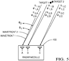
Fig 5 illustrates the wave front with respect to the two scattering centers offigure 4 ; -
Figs 6a, 6b, 6c , are also shown corresponding PSF for target in each of three antenna receive elements (channels); -
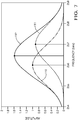
Figure 7 ,8 , and9 show simulated amplitude spectrum (amplitude vs. frequency bins shown as a 1-D cut through a 2-D frequency map) for 3 RX channels. - Automotive radar is used as a sensor for partially automated or fully autonomous operation of vehicles. Depending on angular-resolution requirements of these features, a wide-beam, or relatively narrow-beam transmit and receive antenna(s) or antenna-array(s) may be used, depending on the selected scanning concept (i.e. mechanical or electronics) across a given field-of-view. The transmit antenna radiates Radio Frequency (RF) signal that propagates toward an object in the radar field-of-view. The radio frequency signal is typically a pulse compressed waveform such as a series of waveform pulses commonly called 'chirps' or Frequency Modulated Continuous Wave, Pulse-Doppler and Frequency Shift Key. The signals reflected by the object depend on a backscatter property (i.e. Radar Cross Section) of the object. The signals reflected by the object may be received by receiving antenna-array elements, which are typically connected to single (i.e. time-multiplexed) or multiple (i.e. not time-multiplexed) signal conditioning and processing devices. Depending on the selected receiver techniques (i.e. homodyne or heterodyne), the received RF-signal is converted to discreet baseband signal during propagation through signal conditioning devices chain. For a series of waveform pulses, the baseband signal is transferred from the base time-domain to a Range-Doppler frequency domain by a digital signal processing (or DSP) device, as will be recognized by those in the art. The amplitude of Range-Doppler spectrums from all of the receive antenna-array elements are averaged (i.e. non-coherently integrated). Prior automotive radar systems use this non-coherently integrated amplitude spectral profile as the basis for an object detection schema, i.e. a NCI-detection schem3.
-
Fig. 1 illustrates a non-limiting example of a vehicle based radar system, hereafter referred to as thesystem 10. Thesystem 10 includes anantenna array 12 that may include a transmit-element 14, and an array of receive elements, hereafter referred to as a plurality ofantennas 16. It is recognized that one or more of the antenna elements that make up theantenna array 12 could be used to both transmit aradar signal 18, and output a detectedsignal 30 indicative of reflected radar signals 20 reflected by afirst object 24A or asecond object 24B in a field-of-view 22 of thesystem 10. The transmit-element 14 and the plurality ofantennas 16 are illustrated as distinct elements in this example only to simplify the explanation of thesystem 10. The first and second objects (target objects) may be suitable if stationary as landmarks, and if they are single scatterers. - The
system 10 may also include acontroller 26 configured to output a transmit-signal 28 to the transmit-element 14, and configured to receive detectedsignals 30 from each antenna, for example afirst signal 30A from afirst antenna 16A and asecond signal 30B from asecond antenna 16B. Each of the detected signals 30 correspond to the reflectedradar signal 20 that was detected by one of the plurality ofantennas 16. Thecontroller 26 may include aprocessor 27 such as a microprocessor, digital signal processor, or other control/signal conditioning circuitry such as analog and/or digital control circuitry including an application specific integrated circuit (ASIC) for processing data, as should be evident to those in the art. Thecontroller 26 may include memory (not shown), including non-volatile memory, such as electrically erasable programmable read-only memory (EEPROM) for storing one or more routines, thresholds and captured data. The one or more routines may be executed by theprocessor 27 to perform steps for determining if the detected signals 30 received by thecontroller 26 indicate the presence of thefirst object 24A and/or thesecond object 24B, as described herein. - To meet customer specified angular-resolution requirements of automotive radar systems, such systems often use antennas that have relatively narrow transmit and receive beam-widths to scan a field-of-view for objects. In this non-limiting example, the transmit-
element 14 radiates or emits theradar signal 18 toward thefirst object 24A and/or thesecond object 24B in a field-of-view 22, and each of the plurality ofantennas 16 detects a reflected radar signal reflected by thefirst object 24A and/or thesecond object 24B in the field-of-view 22 of thesystem 10. - Characteristics of the reflected
radar signal 20 depend on a backscatter property or radar cross section (RCS) of thefirst object 24A or thesecond object 24B. Depending on the signal waveform and the modulation system used, thecontroller 26 may transform the time domain signals (the detected signals 30) to the frequency domain so, for example, the spectrums can be combined using, for example, non-coherent integration (NCI). Some automotive radar systems use this non-coherently integrated spectral data as the basis for object detection, and evaluate the spectral data to determine the position and Doppler parameter estimates that have higher spectral magnitude than a defined detection threshold. NCI is generally preferred to suppress noise induced variation and thereby keep noise induced false alarm rates to a minimum. - The problem of determination if a radar backscatter return originates from a single scattering center (of a target object) is solved using an efficient method of a 2-D amplitude spectral evaluation (in the range-Doppler domain) where information from multiple receiver (RX) channels is processed. The methodology may for example utilize the system as described above.
- In the proposed method, N 2-D range-Doppler maps from N RX channels are analyzed. (e.g.) Typically, the data is arranged in terms of a set of frequency ranges - so called Doppler "bins". As it is a matter of interference between signals reflected from scattering centers located in relative close proximity to each other in space, amplitude spectral information from the (2-D) measured complex data (in the range-Doppler domain) are evaluated at the position of the resulting "peak" with respect to each RX channel to determine if the measured response originates from a single scattering center or not.
- Typically antenna systems used on vehicles comprise a plurality of antennas/receiving elements arranged as an antenna array. This allows beam forming. Different scatterers produce different range-Doppler responses (maps) across the plurality of those N RX channels.
- In a method according to the invention, the position of the maximum of the amplitude (or power) spectrum for the available N RX channels of the radar module is estimated/ interpolated and the variation among these N estimates in respect of the N RX channels is analyzed.
- If the peak maximum does not occur at the same position (in the range-Doppler map) for those N estimates (taking into account an uncertainty of the estimates), then the target is considered to be a non-single scatterer.
- In the case of a single scatterer, the peak maximum would be namely at the same position (in the range-Doppler map, taking some uncertainty into account) for those N RX channels.
- In one example, the following methodology is implemented, with reference to
figure 2 . - A radar system comprising an antenna receive array having multiple (N) receive (RX) channels sends out a radar signal and so the received reflected signal form a target is received by N receiver channels and processed. The subsequent processing i.e. analysis is described with reference to flowchart of
figure 2 . - In step S1, from the signals received by the antenna array, amplitude and/or power spectral information, from the N available range-Doppler maps is extracted (for each of the N RX channels);
- S2 is the step of determining the position of the maximum (peak) amplitude (or power) spectrum for those N RX channels (N estimates); this may be done by suitable interpolation; so the 2D peak position is determined. The process will therefore determine the frequency (or frequency bin) which has the max (peak) amplitude, in respect of each N RX channel.
- In step S3, the extent of the variation of the position (in terms of frequency/frequency bin) in the range Doppler map amongst the N RX channels data is determined.
- In subsequent steps S4 and S5 the degree of variation of frequency /frequency bin which correlate to maximum/peak power is determined and the test for a single scatterer is based on the degree of variation - the less variation the more the target is considered a single scatterer.
- So for example in step S4 the extent to which the target is a single scatterer based on these results from step S3. Specifically in this example, for example if the variation among the N estimated peak positions is above a threshold then the target object is considered to be a non-single scatterer.
- In
Figure 2 , a flowchart of the algorithmic processing steps described above is presented. - Without loss of generality, for a better visualization of the problem being solved by the proposed method, a shift/mismatch between the target responses (PSFs) along the Doppler dimension is not considered here. However, the proposed method can be applied on 1-D as well as on 2-D (like the range-Doppler map) spectral data.
- Consider the situation where a single scattering center (Target 1) is present in the sensed scene (see
Figure 3 ). There are three receiver elements (channels) designated A, B and C inradar module 100. When the angle of incidence is θ1, and the resulting range frequency is fR ∝ R, then R1,A ≈ R1,B ≈ R1,C → fR1,A ≈ fR1,B ≈ fR1,C. Thus, the corresponding PSF1 in respect of Target 1 (for the antennas A, B, C are designated PSF1,A , PSF1,B , PSF1,C) are shown infigures 6a, 6b and 6c positioned at almost the same range frequency fR1,n for the N RX channels (here exemplarily called antenna receive elements A, B, and C). Nevertheless, R1,A ≠ R1,B ≠ R1,C → ϕR1,A ≠ ϕR1,B ≠ ϕR1,C. Therefore, generally the phases of the corresponding PSFs are different for the N RX channels. - Consider a situation where a second scattering center (named Target 2) is placed in a close proximity to
Target 1 in space. This is shown infigure 4 and the wave front with respect to the two scattering centers are shown in comparison infigure 5 . - In
figure 6a, 6b, 6c , are also shown corresponding PSF for target to in each of three antenna receive elements (channels) respectively designated PSF2,A, PSF2,B,PSF 2,C. Then, at the N available RX channels, a superposition of those two scattered signals occurs (seeFigure 7 ). When its angle of incidence is θ2 and R2,n ≠ R1,n then fR2,n ≠ fR1,n and ϕR2,n ≠ ϕR1,n. - So
figure 6a, 6b, and 6c shows the two targets and the corresponding backscatter signals together. If |R2,n - R1,n | < range resolution limit, then the two targets cannot be resolved in the spectral domain. Thus, due to the overlapping/superposition of thePSF 1 and PSF 2 a non-single scatterer response is observed on each RX channel. - A case was simulated where two PSFs with a frequency distance of 1.0 range bin are put in a close proximity to each other along the range frequency dimension. The targets are considered to be stationary here (without loss of generality). The first PSF (PSF1) has amplitude of 1.0, and the second one (PSF2) has amplitude of 0.9.
- In
Figure 7 ,8 , and9 simulated amplitude spectrum (amplitude vs. frequency bins shown as a 1-D cut through a 2-D frequency map) are given for 3 RX channels. The phases of the individual PSFs have been arbitrarily chosen. As can be seen, the estimated position of the amplitude peaks for the 3 RX channels are not at the same frequency position. Thus, the peak under test is determined to originate from a non-single scatterer. -
Reference numeral 110 shows the PSF forTarget Target 2. Forfigure 7 Target 1 the peak amplitude is atfrequency bin 256 and forTarget 2 this is atfrequency bin 257.Reference numeral 112 shows the superposition of the two PSFs that is from the actual data of the received signal. -
Figure 7 shows the resuts/data for a 1st RX channel (Antenna A) with a 1st PSF: Frequency bin=256.0, Amplitude=1.0, Phi=0deg. 2nd PSF: Frequency bin=257.0, Amplitude=0.9, Phi=30deg. Position of the amplitude peak after the superposition: Frequency bin=256.5. -
Figure 8 shows the data for a 2nd RX channel (Antenna B) 1st PSF: Frequency bin=256.0, Amplitude=1.0, Phi=0deg. 2nd PSF: Frequency bin=257.0, Amplitude=0.9, Phi=120deg. Position of the amplitude peak after the superposition: Frequency bin=256.0. -
Figure 9 shows the data for a 3rd RX channel (Antenna C) 1st PSF: Frequency bin=256.0, Amplitude =1.0, Phi=0deg. 2nd PSF: Frequency bin=257.0, Amplitude =0.9, Phi=135deg. Position of the amplitude peak after the superposition: Frequency bin=255.8. - The technique gives a number of advantages: no phase needs to be calculated, and no symmetry needs to be considered. The method is sensitive, very robust, and has a low computational cost.
Claims (7)
- A vehicle-based method of determining the extent to which a target object is a single scatterer, said vehicle including a radar system including a radar transmit element, adapted to send a radar signal towards said target object, and an antenna receive array comprising a plurality M of a receive elements, providing a corresponding plurality of N radar receive channels, and adapted to receive radar signals reflected from said target object, said method comprising:a) transmitting a radar signal from said radar transmit element to said target object;b) receiving the reflected signal of the signal transmitted in step a) from the target object at said plurality of receiver elements;c) for each antenna element or channel, processing the received signal to provide amplitude or power data in the frequency domain;d) with respect to the data in step c), for each receive element/channel, determining the frequency with the maximum amplitude or power;e) determining the degree of variability of the results of step d) with respect to each receive element/channel;f) determining the extent to which the target object is a single scatterer based on the result of step e).
- A method as claimed in claim 1 where step c) includes for each antenna receive channel, processing the data to provide power or amplitude data in relation to frequency bins comprising discrete frequency ranges, and step d) comprises for each antenna/channel, determining the bin with the maximum amplitude or power; and step e) determines the degree of variability in said bins in respect of each for each receive element/channel.
- A method as claimed in claims 1 or 2 wherein in step c) received signal data is converted from the base time-domain to a range-Doppler frequency domain.
- A method as claimed in claims 1 to 3 wherein step c) includes providing a range-Doppler map in terms of range-Doppler frequency domain for each receive element/channel.
- A method as claimed in claims 2 to 4 wherein step c) includes providing power or amplitude data in term of Doppler bins.
- A method as claimed in claims 1 to 5 wherein in step c) the power or amplitude data is determined from amplitude spectral information from 1-D or 2-D data in the range-Doppler (frequency) domain.
- A method as claimed any preceding claim wherein step f) comprises determining if the degree of variability from step e) is above or below a threshold, and determining either that the target object is a single scatterer if the degree of variability is below said threshold or that the target object is a non-single scatterer if the variation is above said threshold.
Priority Applications (3)
| Application Number | Priority Date | Filing Date | Title |
|---|---|---|---|
| EP17190581.3A EP3454081B1 (en) | 2017-09-12 | 2017-09-12 | Single scatterer test using amplitude and a plurality of receive elements |
| US16/106,486 US10989809B2 (en) | 2017-09-12 | 2018-08-21 | Single scatterer test using amplitude and a plurality of receive elements |
| CN201811056318.6A CN109490872B (en) | 2017-09-12 | 2018-09-11 | Single scatterer test using amplitude and multiple receiving elements |
Applications Claiming Priority (1)
| Application Number | Priority Date | Filing Date | Title |
|---|---|---|---|
| EP17190581.3A EP3454081B1 (en) | 2017-09-12 | 2017-09-12 | Single scatterer test using amplitude and a plurality of receive elements |
Publications (2)
| Publication Number | Publication Date |
|---|---|
| EP3454081A1 true EP3454081A1 (en) | 2019-03-13 |
| EP3454081B1 EP3454081B1 (en) | 2023-11-01 |
Family
ID=59856454
Family Applications (1)
| Application Number | Title | Priority Date | Filing Date |
|---|---|---|---|
| EP17190581.3A Active EP3454081B1 (en) | 2017-09-12 | 2017-09-12 | Single scatterer test using amplitude and a plurality of receive elements |
Country Status (3)
| Country | Link |
|---|---|
| US (1) | US10989809B2 (en) |
| EP (1) | EP3454081B1 (en) |
| CN (1) | CN109490872B (en) |
Cited By (3)
| Publication number | Priority date | Publication date | Assignee | Title |
|---|---|---|---|---|
| CN113589269A (en) * | 2021-07-14 | 2021-11-02 | 太原理工大学 | Passive multi-base-station radar target detection method based on linear fusion |
| US11619707B1 (en) | 2021-10-01 | 2023-04-04 | Aptiv Technologies Limited | Method and system for calibrating a radar sensor |
| EP4187276A1 (en) | 2021-11-30 | 2023-05-31 | Aptiv Technologies Limited | Method and system for estimating a radar calibration matrix |
Families Citing this family (6)
| Publication number | Priority date | Publication date | Assignee | Title |
|---|---|---|---|---|
| EP3546978B1 (en) * | 2018-03-29 | 2021-12-08 | Aptiv Technologies Limited | Method for testing a target object as single point scattering center |
| CN110261847B (en) * | 2019-06-19 | 2024-05-28 | 深圳数联天下智能科技有限公司 | Object position determining method and device |
| US20240201337A1 (en) * | 2019-08-20 | 2024-06-20 | Luminar, Llc | Coherent pulsed lidar system |
| US20240094357A1 (en) * | 2019-08-20 | 2024-03-21 | Luminar, Llc | Coherent pulsed lidar system |
| CN112673272B (en) * | 2020-07-27 | 2022-03-11 | 华为技术有限公司 | A signal processing method, device and storage medium |
| US20240369703A1 (en) * | 2023-04-28 | 2024-11-07 | Arizona Board Of Regents On Behalf Of Arizona State University | Neural volumetric reconstruction for coherent synthetic aperture sonar |
Citations (3)
| Publication number | Priority date | Publication date | Assignee | Title |
|---|---|---|---|---|
| EP2998761A1 (en) * | 2014-09-19 | 2016-03-23 | Delphi Technologies, Inc. | Radar system with phase based multi-target detection |
| US20160084943A1 (en) * | 2014-09-19 | 2016-03-24 | Delphi Technologies, Inc. | Radar System For Automated Vehicle With Phase Change Based Target Catagorization |
| EP3144696A1 (en) * | 2015-09-15 | 2017-03-22 | Delphi Technologies, Inc. | Radar system for automated vehicle with phase change based target categorization |
Family Cites Families (18)
| Publication number | Priority date | Publication date | Assignee | Title |
|---|---|---|---|---|
| US4527161A (en) * | 1981-09-08 | 1985-07-02 | The United States Of America As Represented By The Secretary Of The Navy | 3D Imaging with stepped frequency waveforms and monopulse processing |
| IT1181998B (en) * | 1985-12-24 | 1987-09-30 | Selenia Ind Elettroniche | SYNTHETIC OPENING SIGNAL PROCESSOR FOR RADAR PARTICULARLY SUITABLE FOR PARALLEL CALCULATION |
| US5248976A (en) * | 1991-11-27 | 1993-09-28 | Hughes Aircraft Company | Multiple discrete autofocus |
| US5270718A (en) * | 1992-08-21 | 1993-12-14 | Technology Service Corporation | Method and apparatus for tracking targets from direct and multipath reflected radar signals |
| JP3678946B2 (en) * | 1999-07-28 | 2005-08-03 | 三菱電機株式会社 | Synthetic aperture radar device and target scattering point detection method in the synthetic aperture radar device |
| US6825800B1 (en) * | 2003-05-13 | 2004-11-30 | Sandia Corporation | Waveform synthesis for imaging and ranging applications |
| AU2003286083A1 (en) * | 2003-07-19 | 2005-02-04 | Gamma Remote Sensing Research And Consulting Ag | Method to improve interferometric signatures by coherent point scatterers |
| US7511655B2 (en) * | 2006-09-25 | 2009-03-31 | The United States Of America As Represented By The Secretary Of The Navy | Method and apparatus for 3-D sub-voxel position imaging with synthetic aperture radar |
| US8125370B1 (en) * | 2007-04-16 | 2012-02-28 | The United States Of America As Represented By The Secretary Of The Navy | Polarimetric synthetic aperture radar signature detector |
| US8044846B1 (en) | 2007-11-29 | 2011-10-25 | Lockheed Martin Corporation | Method for deblurring radar range-doppler images |
| US8154435B2 (en) * | 2008-08-22 | 2012-04-10 | Microsoft Corporation | Stability monitoring using synthetic aperture radar |
| EP2520946A1 (en) * | 2011-05-04 | 2012-11-07 | BAE Systems Plc | Radar system and methods of controlling a radar system and the provision of a range-doppler target image signature |
| PL2614384T3 (en) * | 2010-09-08 | 2016-09-30 | Radar system and methods of controlling a radar system and the provision of a range-doppler target image signature | |
| CN102129067B (en) * | 2011-03-15 | 2013-07-03 | 北京理工大学 | Ground moving target signal modeling and imaging method for forward scattering radar (FSR) |
| JP6188429B2 (en) | 2013-06-03 | 2017-08-30 | 三菱電機株式会社 | Clutter suppression device |
| US9310468B2 (en) * | 2014-05-15 | 2016-04-12 | Delphi Technologies, Inc. | Radar system with improved multi-target discrimination |
| US10054672B2 (en) | 2015-08-31 | 2018-08-21 | Veoneer Us, Inc. | Apparatus and method for detecting and correcting for blockage of an automotive radar sensor |
| EP3546978B1 (en) | 2018-03-29 | 2021-12-08 | Aptiv Technologies Limited | Method for testing a target object as single point scattering center |
-
2017
- 2017-09-12 EP EP17190581.3A patent/EP3454081B1/en active Active
-
2018
- 2018-08-21 US US16/106,486 patent/US10989809B2/en active Active
- 2018-09-11 CN CN201811056318.6A patent/CN109490872B/en active Active
Patent Citations (3)
| Publication number | Priority date | Publication date | Assignee | Title |
|---|---|---|---|---|
| EP2998761A1 (en) * | 2014-09-19 | 2016-03-23 | Delphi Technologies, Inc. | Radar system with phase based multi-target detection |
| US20160084943A1 (en) * | 2014-09-19 | 2016-03-24 | Delphi Technologies, Inc. | Radar System For Automated Vehicle With Phase Change Based Target Catagorization |
| EP3144696A1 (en) * | 2015-09-15 | 2017-03-22 | Delphi Technologies, Inc. | Radar system for automated vehicle with phase change based target categorization |
Cited By (6)
| Publication number | Priority date | Publication date | Assignee | Title |
|---|---|---|---|---|
| CN113589269A (en) * | 2021-07-14 | 2021-11-02 | 太原理工大学 | Passive multi-base-station radar target detection method based on linear fusion |
| CN113589269B (en) * | 2021-07-14 | 2023-07-21 | 太原理工大学 | Passive multi-base station radar target detection method based on linear fusion |
| US11619707B1 (en) | 2021-10-01 | 2023-04-04 | Aptiv Technologies Limited | Method and system for calibrating a radar sensor |
| EP4160256A1 (en) | 2021-10-01 | 2023-04-05 | Aptiv Technologies Limited | Method and system for calibrating a radar sensor |
| EP4187276A1 (en) | 2021-11-30 | 2023-05-31 | Aptiv Technologies Limited | Method and system for estimating a radar calibration matrix |
| US12455347B2 (en) | 2021-11-30 | 2025-10-28 | Aptiv Technologies AG | Method and system for estimating a radar calibration matrix |
Also Published As
| Publication number | Publication date |
|---|---|
| US10989809B2 (en) | 2021-04-27 |
| CN109490872B (en) | 2023-07-25 |
| EP3454081B1 (en) | 2023-11-01 |
| CN109490872A (en) | 2019-03-19 |
| US20190079180A1 (en) | 2019-03-14 |
Similar Documents
| Publication | Publication Date | Title |
|---|---|---|
| US10989809B2 (en) | Single scatterer test using amplitude and a plurality of receive elements | |
| CN109490874B (en) | Method for determining the suitability of a radar target as a location landmark | |
| EP3546978B1 (en) | Method for testing a target object as single point scattering center | |
| US9470777B2 (en) | Radar system for automated vehicle with phase change based target catagorization | |
| US10416299B2 (en) | MIMO radar measurement sensor | |
| US20190242972A1 (en) | Radar sensing with phase correction | |
| CN105093213B (en) | Radar system with improved multi-target discrimination | |
| US11105919B2 (en) | Vehicle radar for environmental detection | |
| US20170131393A1 (en) | Radar measurement method with different fields of view | |
| EP2998761A1 (en) | Radar system with phase based multi-target detection | |
| US11841416B2 (en) | Radar system for a vehicle | |
| EP3144696A1 (en) | Radar system for automated vehicle with phase change based target categorization | |
| US20210116536A1 (en) | Method and radar device for ascertaining radial relative acceleration of at least one target | |
| EP3454080B1 (en) | Single scatterer test using phase change | |
| KR20200120685A (en) | Angle estimation and ambiguity constant determination of radar sensor for automobile with large antenna array | |
| US11971472B2 (en) | Method for determining an ego-velocity estimated value and an angle estimated value of targets | |
| US11644564B2 (en) | Method for signal evaluation in a locating system that includes multiple radar sensors | |
| EP2096457B1 (en) | Digital beam forming using frequency-modulated signals | |
| US11333754B2 (en) | Detection of parking row orientation | |
| Zaumseil et al. | Radar-based near field environment perception using back projection algorithm | |
| EP4417998B1 (en) | Fine-near-range estimation method for automotive radar applications |
Legal Events
| Date | Code | Title | Description |
|---|---|---|---|
| PUAI | Public reference made under article 153(3) epc to a published international application that has entered the european phase |
Free format text: ORIGINAL CODE: 0009012 |
|
| STAA | Information on the status of an ep patent application or granted ep patent |
Free format text: STATUS: THE APPLICATION HAS BEEN PUBLISHED |
|
| AK | Designated contracting states |
Kind code of ref document: A1 Designated state(s): AL AT BE BG CH CY CZ DE DK EE ES FI FR GB GR HR HU IE IS IT LI LT LU LV MC MK MT NL NO PL PT RO RS SE SI SK SM TR |
|
| AX | Request for extension of the european patent |
Extension state: BA ME |
|
| STAA | Information on the status of an ep patent application or granted ep patent |
Free format text: STATUS: REQUEST FOR EXAMINATION WAS MADE |
|
| 17P | Request for examination filed |
Effective date: 20190913 |
|
| RBV | Designated contracting states (corrected) |
Designated state(s): AL AT BE BG CH CY CZ DE DK EE ES FI FR GB GR HR HU IE IS IT LI LT LU LV MC MK MT NL NO PL PT RO RS SE SI SK SM TR |
|
| STAA | Information on the status of an ep patent application or granted ep patent |
Free format text: STATUS: EXAMINATION IS IN PROGRESS |
|
| 17Q | First examination report despatched |
Effective date: 20210222 |
|
| RAP3 | Party data changed (applicant data changed or rights of an application transferred) |
Owner name: APTIV TECHNOLOGIES LIMITED |
|
| GRAP | Despatch of communication of intention to grant a patent |
Free format text: ORIGINAL CODE: EPIDOSNIGR1 |
|
| STAA | Information on the status of an ep patent application or granted ep patent |
Free format text: STATUS: GRANT OF PATENT IS INTENDED |
|
| RIC1 | Information provided on ipc code assigned before grant |
Ipc: G01S 13/02 20060101ALN20230428BHEP Ipc: G01S 13/72 20060101ALN20230428BHEP Ipc: G01S 13/58 20060101ALN20230428BHEP Ipc: G01S 13/931 20200101ALI20230428BHEP Ipc: G01S 13/42 20060101ALI20230428BHEP Ipc: G01S 7/41 20060101AFI20230428BHEP |
|
| RIC1 | Information provided on ipc code assigned before grant |
Ipc: G01S 13/02 20060101ALN20230505BHEP Ipc: G01S 13/72 20060101ALN20230505BHEP Ipc: G01S 13/58 20060101ALN20230505BHEP Ipc: G01S 13/931 20200101ALI20230505BHEP Ipc: G01S 13/42 20060101ALI20230505BHEP Ipc: G01S 7/41 20060101AFI20230505BHEP |
|
| INTG | Intention to grant announced |
Effective date: 20230524 |
|
| GRAS | Grant fee paid |
Free format text: ORIGINAL CODE: EPIDOSNIGR3 |
|
| GRAA | (expected) grant |
Free format text: ORIGINAL CODE: 0009210 |
|
| STAA | Information on the status of an ep patent application or granted ep patent |
Free format text: STATUS: THE PATENT HAS BEEN GRANTED |
|
| AK | Designated contracting states |
Kind code of ref document: B1 Designated state(s): AL AT BE BG CH CY CZ DE DK EE ES FI FR GB GR HR HU IE IS IT LI LT LU LV MC MK MT NL NO PL PT RO RS SE SI SK SM TR |
|
| REG | Reference to a national code |
Ref country code: GB Ref legal event code: FG4D |
|
| REG | Reference to a national code |
Ref country code: CH Ref legal event code: EP |
|
| REG | Reference to a national code |
Ref country code: IE Ref legal event code: FG4D |
|
| REG | Reference to a national code |
Ref country code: DE Ref legal event code: R096 Ref document number: 602017075930 Country of ref document: DE |
|
| P01 | Opt-out of the competence of the unified patent court (upc) registered |
Effective date: 20231114 |
|
| REG | Reference to a national code |
Ref country code: LT Ref legal event code: MG9D |
|
| REG | Reference to a national code |
Ref country code: NL Ref legal event code: MP Effective date: 20231101 |
|
| PG25 | Lapsed in a contracting state [announced via postgrant information from national office to epo] |
Ref country code: GR Free format text: LAPSE BECAUSE OF FAILURE TO SUBMIT A TRANSLATION OF THE DESCRIPTION OR TO PAY THE FEE WITHIN THE PRESCRIBED TIME-LIMIT Effective date: 20240202 |
|
| PG25 | Lapsed in a contracting state [announced via postgrant information from national office to epo] |
Ref country code: IS Free format text: LAPSE BECAUSE OF FAILURE TO SUBMIT A TRANSLATION OF THE DESCRIPTION OR TO PAY THE FEE WITHIN THE PRESCRIBED TIME-LIMIT Effective date: 20240301 |
|
| PG25 | Lapsed in a contracting state [announced via postgrant information from national office to epo] |
Ref country code: LT Free format text: LAPSE BECAUSE OF FAILURE TO SUBMIT A TRANSLATION OF THE DESCRIPTION OR TO PAY THE FEE WITHIN THE PRESCRIBED TIME-LIMIT Effective date: 20231101 |
|
| REG | Reference to a national code |
Ref country code: AT Ref legal event code: MK05 Ref document number: 1627824 Country of ref document: AT Kind code of ref document: T Effective date: 20231101 |
|
| PG25 | Lapsed in a contracting state [announced via postgrant information from national office to epo] |
Ref country code: NL Free format text: LAPSE BECAUSE OF FAILURE TO SUBMIT A TRANSLATION OF THE DESCRIPTION OR TO PAY THE FEE WITHIN THE PRESCRIBED TIME-LIMIT Effective date: 20231101 |
|
| PG25 | Lapsed in a contracting state [announced via postgrant information from national office to epo] |
Ref country code: AT Free format text: LAPSE BECAUSE OF FAILURE TO SUBMIT A TRANSLATION OF THE DESCRIPTION OR TO PAY THE FEE WITHIN THE PRESCRIBED TIME-LIMIT Effective date: 20231101 |
|
| PG25 | Lapsed in a contracting state [announced via postgrant information from national office to epo] |
Ref country code: ES Free format text: LAPSE BECAUSE OF FAILURE TO SUBMIT A TRANSLATION OF THE DESCRIPTION OR TO PAY THE FEE WITHIN THE PRESCRIBED TIME-LIMIT Effective date: 20231101 |
|
| PG25 | Lapsed in a contracting state [announced via postgrant information from national office to epo] |
Ref country code: NL Free format text: LAPSE BECAUSE OF FAILURE TO SUBMIT A TRANSLATION OF THE DESCRIPTION OR TO PAY THE FEE WITHIN THE PRESCRIBED TIME-LIMIT Effective date: 20231101 Ref country code: LT Free format text: LAPSE BECAUSE OF FAILURE TO SUBMIT A TRANSLATION OF THE DESCRIPTION OR TO PAY THE FEE WITHIN THE PRESCRIBED TIME-LIMIT Effective date: 20231101 Ref country code: IS Free format text: LAPSE BECAUSE OF FAILURE TO SUBMIT A TRANSLATION OF THE DESCRIPTION OR TO PAY THE FEE WITHIN THE PRESCRIBED TIME-LIMIT Effective date: 20240301 Ref country code: GR Free format text: LAPSE BECAUSE OF FAILURE TO SUBMIT A TRANSLATION OF THE DESCRIPTION OR TO PAY THE FEE WITHIN THE PRESCRIBED TIME-LIMIT Effective date: 20240202 Ref country code: ES Free format text: LAPSE BECAUSE OF FAILURE TO SUBMIT A TRANSLATION OF THE DESCRIPTION OR TO PAY THE FEE WITHIN THE PRESCRIBED TIME-LIMIT Effective date: 20231101 Ref country code: BG Free format text: LAPSE BECAUSE OF FAILURE TO SUBMIT A TRANSLATION OF THE DESCRIPTION OR TO PAY THE FEE WITHIN THE PRESCRIBED TIME-LIMIT Effective date: 20240201 Ref country code: AT Free format text: LAPSE BECAUSE OF FAILURE TO SUBMIT A TRANSLATION OF THE DESCRIPTION OR TO PAY THE FEE WITHIN THE PRESCRIBED TIME-LIMIT Effective date: 20231101 Ref country code: PT Free format text: LAPSE BECAUSE OF FAILURE TO SUBMIT A TRANSLATION OF THE DESCRIPTION OR TO PAY THE FEE WITHIN THE PRESCRIBED TIME-LIMIT Effective date: 20240301 |
|
| PG25 | Lapsed in a contracting state [announced via postgrant information from national office to epo] |
Ref country code: SE Free format text: LAPSE BECAUSE OF FAILURE TO SUBMIT A TRANSLATION OF THE DESCRIPTION OR TO PAY THE FEE WITHIN THE PRESCRIBED TIME-LIMIT Effective date: 20231101 Ref country code: RS Free format text: LAPSE BECAUSE OF FAILURE TO SUBMIT A TRANSLATION OF THE DESCRIPTION OR TO PAY THE FEE WITHIN THE PRESCRIBED TIME-LIMIT Effective date: 20231101 Ref country code: PL Free format text: LAPSE BECAUSE OF FAILURE TO SUBMIT A TRANSLATION OF THE DESCRIPTION OR TO PAY THE FEE WITHIN THE PRESCRIBED TIME-LIMIT Effective date: 20231101 Ref country code: NO Free format text: LAPSE BECAUSE OF FAILURE TO SUBMIT A TRANSLATION OF THE DESCRIPTION OR TO PAY THE FEE WITHIN THE PRESCRIBED TIME-LIMIT Effective date: 20240201 Ref country code: LV Free format text: LAPSE BECAUSE OF FAILURE TO SUBMIT A TRANSLATION OF THE DESCRIPTION OR TO PAY THE FEE WITHIN THE PRESCRIBED TIME-LIMIT Effective date: 20231101 Ref country code: HR Free format text: LAPSE BECAUSE OF FAILURE TO SUBMIT A TRANSLATION OF THE DESCRIPTION OR TO PAY THE FEE WITHIN THE PRESCRIBED TIME-LIMIT Effective date: 20231101 |
|
| PG25 | Lapsed in a contracting state [announced via postgrant information from national office to epo] |
Ref country code: DK Free format text: LAPSE BECAUSE OF FAILURE TO SUBMIT A TRANSLATION OF THE DESCRIPTION OR TO PAY THE FEE WITHIN THE PRESCRIBED TIME-LIMIT Effective date: 20231101 |
|
| PG25 | Lapsed in a contracting state [announced via postgrant information from national office to epo] |
Ref country code: CZ Free format text: LAPSE BECAUSE OF FAILURE TO SUBMIT A TRANSLATION OF THE DESCRIPTION OR TO PAY THE FEE WITHIN THE PRESCRIBED TIME-LIMIT Effective date: 20231101 |
|
| PG25 | Lapsed in a contracting state [announced via postgrant information from national office to epo] |
Ref country code: SK Free format text: LAPSE BECAUSE OF FAILURE TO SUBMIT A TRANSLATION OF THE DESCRIPTION OR TO PAY THE FEE WITHIN THE PRESCRIBED TIME-LIMIT Effective date: 20231101 |
|
| PG25 | Lapsed in a contracting state [announced via postgrant information from national office to epo] |
Ref country code: SM Free format text: LAPSE BECAUSE OF FAILURE TO SUBMIT A TRANSLATION OF THE DESCRIPTION OR TO PAY THE FEE WITHIN THE PRESCRIBED TIME-LIMIT Effective date: 20231101 Ref country code: SK Free format text: LAPSE BECAUSE OF FAILURE TO SUBMIT A TRANSLATION OF THE DESCRIPTION OR TO PAY THE FEE WITHIN THE PRESCRIBED TIME-LIMIT Effective date: 20231101 Ref country code: RO Free format text: LAPSE BECAUSE OF FAILURE TO SUBMIT A TRANSLATION OF THE DESCRIPTION OR TO PAY THE FEE WITHIN THE PRESCRIBED TIME-LIMIT Effective date: 20231101 Ref country code: IT Free format text: LAPSE BECAUSE OF FAILURE TO SUBMIT A TRANSLATION OF THE DESCRIPTION OR TO PAY THE FEE WITHIN THE PRESCRIBED TIME-LIMIT Effective date: 20231101 Ref country code: EE Free format text: LAPSE BECAUSE OF FAILURE TO SUBMIT A TRANSLATION OF THE DESCRIPTION OR TO PAY THE FEE WITHIN THE PRESCRIBED TIME-LIMIT Effective date: 20231101 Ref country code: DK Free format text: LAPSE BECAUSE OF FAILURE TO SUBMIT A TRANSLATION OF THE DESCRIPTION OR TO PAY THE FEE WITHIN THE PRESCRIBED TIME-LIMIT Effective date: 20231101 Ref country code: CZ Free format text: LAPSE BECAUSE OF FAILURE TO SUBMIT A TRANSLATION OF THE DESCRIPTION OR TO PAY THE FEE WITHIN THE PRESCRIBED TIME-LIMIT Effective date: 20231101 |
|
| REG | Reference to a national code |
Ref country code: DE Ref legal event code: R097 Ref document number: 602017075930 Country of ref document: DE |
|
| PLBE | No opposition filed within time limit |
Free format text: ORIGINAL CODE: 0009261 |
|
| STAA | Information on the status of an ep patent application or granted ep patent |
Free format text: STATUS: NO OPPOSITION FILED WITHIN TIME LIMIT |
|
| 26N | No opposition filed |
Effective date: 20240802 |
|
| PG25 | Lapsed in a contracting state [announced via postgrant information from national office to epo] |
Ref country code: SI Free format text: LAPSE BECAUSE OF FAILURE TO SUBMIT A TRANSLATION OF THE DESCRIPTION OR TO PAY THE FEE WITHIN THE PRESCRIBED TIME-LIMIT Effective date: 20231101 |
|
| PG25 | Lapsed in a contracting state [announced via postgrant information from national office to epo] |
Ref country code: SI Free format text: LAPSE BECAUSE OF FAILURE TO SUBMIT A TRANSLATION OF THE DESCRIPTION OR TO PAY THE FEE WITHIN THE PRESCRIBED TIME-LIMIT Effective date: 20231101 |
|
| PG25 | Lapsed in a contracting state [announced via postgrant information from national office to epo] |
Ref country code: MC Free format text: LAPSE BECAUSE OF FAILURE TO SUBMIT A TRANSLATION OF THE DESCRIPTION OR TO PAY THE FEE WITHIN THE PRESCRIBED TIME-LIMIT Effective date: 20231101 |
|
| REG | Reference to a national code |
Ref country code: DE Ref legal event code: R081 Ref document number: 602017075930 Country of ref document: DE Owner name: APTIV TECHNOLOGIES AG, CH Free format text: FORMER OWNER: APTIV TECHNOLOGIES LIMITED, ST. MICHAEL, BB Ref country code: CH Ref legal event code: PL |
|
| PG25 | Lapsed in a contracting state [announced via postgrant information from national office to epo] |
Ref country code: LU Free format text: LAPSE BECAUSE OF NON-PAYMENT OF DUE FEES Effective date: 20240912 |
|
| REG | Reference to a national code |
Ref country code: BE Ref legal event code: MM Effective date: 20240930 |
|
| PG25 | Lapsed in a contracting state [announced via postgrant information from national office to epo] |
Ref country code: BE Free format text: LAPSE BECAUSE OF NON-PAYMENT OF DUE FEES Effective date: 20240930 |
|
| PG25 | Lapsed in a contracting state [announced via postgrant information from national office to epo] |
Ref country code: CH Free format text: LAPSE BECAUSE OF NON-PAYMENT OF DUE FEES Effective date: 20240930 |
|
| PG25 | Lapsed in a contracting state [announced via postgrant information from national office to epo] |
Ref country code: IE Free format text: LAPSE BECAUSE OF NON-PAYMENT OF DUE FEES Effective date: 20240912 |
|
| PG25 | Lapsed in a contracting state [announced via postgrant information from national office to epo] |
Ref country code: FI Free format text: LAPSE BECAUSE OF FAILURE TO SUBMIT A TRANSLATION OF THE DESCRIPTION OR TO PAY THE FEE WITHIN THE PRESCRIBED TIME-LIMIT Effective date: 20231101 |
|
| PGFP | Annual fee paid to national office [announced via postgrant information from national office to epo] |
Ref country code: DE Payment date: 20250814 Year of fee payment: 9 |
|
| PGFP | Annual fee paid to national office [announced via postgrant information from national office to epo] |
Ref country code: GB Payment date: 20250818 Year of fee payment: 9 |
|
| PGFP | Annual fee paid to national office [announced via postgrant information from national office to epo] |
Ref country code: FR Payment date: 20250812 Year of fee payment: 9 |
|
| PG25 | Lapsed in a contracting state [announced via postgrant information from national office to epo] |
Ref country code: CY Free format text: LAPSE BECAUSE OF FAILURE TO SUBMIT A TRANSLATION OF THE DESCRIPTION OR TO PAY THE FEE WITHIN THE PRESCRIBED TIME-LIMIT; INVALID AB INITIO Effective date: 20170912 |
|
| PG25 | Lapsed in a contracting state [announced via postgrant information from national office to epo] |
Ref country code: HU Free format text: LAPSE BECAUSE OF FAILURE TO SUBMIT A TRANSLATION OF THE DESCRIPTION OR TO PAY THE FEE WITHIN THE PRESCRIBED TIME-LIMIT; INVALID AB INITIO Effective date: 20170912 |